Embed Size (px)
Citation preview
MIL-STD-188-124BMETRIC 1 Feb 92
SUPERSEDINGMIL-STD-188-124A2 FEBRUARY 1984
MILITARY STANDARD
GROUNDING, BONDING AND SHIELDING
for CommonLong Haul/Tactical Communication SystemsIncluding Ground Based Communications-
Electronics Facilities and Equipments
AMSC N/A AREA SLHC/TCTS/EMCSDISTRIBUTON STATEMENT A. Approved for public release; distribution is unlimited.
MIL-STD-188-124B
ii
FOREWORD
1. This Military Standard is approved and mandatory for use by All Departments and Agencies of theDepartment of Defense in accordance with Department of Defense Instruction 5000.2, dated 23 February 1991.
2. Beneficial comments (recommendations, additions, deletions) and any pertinent data which may be of use in improving thisdocument should be addressed to: TIC/TIS, Scott AFB IL 62225-6343, by using the self-addressed StandardizationDocument Improvement Proposal (DD Form 1426) appearing at the end of this document or by letter.
3. Standards for all military communications are published as part of a MIL-STD-188 series of documents: MilitaryCommunications System Technical Standards are subdivided into Common Long Haul/Tactical Standards (MIL-STD-188-100series), Tactical Standards (MIL-STD-188-200 series) and Long Haul Standards (MIL-STD-188-300 series).
4. This document contains technical standards and design objectives to ensure the optimum performance of ground-basedtelecommunications C-E equipment installations. This is accomplished by reducing noise and by providing adequate protectionagainst power system faults and lightning strikes. Thorough consideration must be given to the grounding of equipment and facilityinstallations, the bonding required, and the methods of shielding and implementation needed for personnel safety and equipmentcontrol.
5. This standard is also recommended for applicable use on any ground facility or equipment where grounding, bonding, shielding,personnel safety, lightning and EMC are required. Examples of such facilities are aircraft simulators, computer centers, laboratorybuildings, weapons checkout and assembly, etc.
6. Paragraph 5. 1, Grounding, for this standard is divided as follows:
I. Detailed requirements for facilities, including buildings and associated structures used principallyfor C-E equipment.
II. Detailed requirements for C-E equipment which address grounding, bonding, and shielding for tactical/long haul fixed ground transportables and military communications electronics equipment installations
and associated subsystems.
7. Detailed requirements for Bonding and Shielding are contained in 5.2 and 5.3.
8. This standard is further implemented by MIL-HDBK-419; Grounding, Bonding, and Shielding for ElectronicFacilities and Equipments.
9. Notations are not used in this revision to identify changes with respect to the previous issue due to the extensiveness of thechanges.
MIL-STD-188-124B
iii
CONTENTS
Paragraph Page1. SCOPE 11.1 Purpose 11.2 Content 11.3 Applications 11.4 Objectives 11.5 System Standards and Design Objectives 1
2. REFERENCED DOCUMENTS 22.1 Government Documents 22.1.1 Specifications, Standards, and Handbooks 22.1.2 Other Government Documents, Drawings, and Publications 32.2 Other Publications 32.3 Source of Documents 42.4 Order of Precedence 4
3. DEFINITIONS 5
4. GENERAL REQUIREMENTS 64.1 General 64.2 Grounding 64.2.1 General 64.2.2 Tactical Equipments and Facilities 64.2.3 Grounding in Arctic Regions 64.3 Bonding 64.4 Shielding 7
5. DETAILED REQUIREMENTS 85.1 Grounding 85.1.1 Building and Structure 85.1.1.1 Earth Electrode Subsystem 85.1.1.1.2 Earth Resistivity Survey 85.1.1.1.3 Minimum Configuration 85.1.1.1.3.1 Resistance to Earth 85.1.1.1.3.2 Additional Considerations 95.1.1.1.4 Ground Rods 95.1.1.1.5 Connecting Risers 95.1.1.1.6 Other Underground Metals 95.1.1.1.7 Resistance Checks 145.1.1.2 Fault Protection Subsystem 145.1.1.2.1 General 145.1.1.2.2 Building Structural Steel 145.1.1.2.3 Pipes and Tubes 145.1.1.2.4 Electrical Supporting Structures 14
MIL-STD-188-124B
iv
CONTENTS (Con't)
Paragraph Page5.1.1.2.4.1 Conduit 145.1.1.2.4.2 Cable Trays or Raceways 155.1.1.2.4.3 Wiring System Enclosures 155.1.1.2.4.4 Metallic Power Cable Sheaths 155.1.1.2.5 Electrical Power Systems 155.1.1.2.5.1 AC Distribution Systems 155.1.1.2.5.1.1 Single Building with Multiple Power Sources 155.1.1.2.5.1.2 Multiple Buildings with Single Power Source 155.1.1.2.5.2 Standby AC Generators 155.1.1.2.5.3 AC Outlets 155.1.1.2.5.4 Electrical Motors and Generators 165.1.1.2.5.5 DC Power Sources 165.1.1.2.5.6 Metallic Battery Racks 165.1.1.2.5.7 Ground Fault Circuit Interrupters 165.1.1.2.6 Secure Facilities 165.1.1.3 Lightning Protection Subsystem 165.1.1.3.1 General 165.1.1.3.2 Buildings and Structures 165.1.1.3.3 Down Conductors 175.1.1.3.4 Bonding 175.1.1.3.5 Structural Steel 175.1.1.3.6 Air Terminals (Lightning Rods) 175.1.1.3.7 Guards 185.1.1.3.8 Supporting Structures 185.1.1.3.8.1 Earth Electrode Subsystem 185.1.1.3.8.2 Air Terminals 185.1.1.3.8.3 Antennas 185.1.1.3.8.4 Down Conductors 185.1.1.3.8.5 Waveguide Grounding 185.1.1.3.8.6 Coaxial Cable Grounding 195.1.1.3.9 Exterior Nonstructural Metal Elements 195.1.1.3.10 Exterior Wires and Cables 195.1.1.3.10.1 Conduit 195.1.1.3.10.2 Overhead Guard Wires 195.1.1.3.11 Underground Guard Wires 195.1.1.3.12 Lightning Arrestors 195.1.1.3.13 Security/Perimeter Fences 205.1.1.4 Signal Reference Subsystem 205.1.1.4.1 General 205.1.1.4.2 Higher Frequency Network 205.1.1.4.3 Lower Frequency Network 205.1.2 Communications-Electronics (C-E) Equipment 205.1.2.1 Signal Reference Subsystem 205.1.2.1.1 Higher Frequency Network 205.1.2.1.1.1 Signal Isolation 20
MIL-STD-188-124B
v
CONTENTS (Con't)
Paragraph Page5.1.2.1.1.2 Equipment Signal Ground Terminations 215.1.2.1.1.3 Shield Terminations of Coaxial and Other Higher Frequency Cables... 215.1.2.1.1.4 Overall Shields 215.1.2.2 Fault Protection Subsystem 235.1.2.2.1 General 235.1.2.2.2 Personnel Protection 235.1.2.2.3 AC Power Neutral 235.1.2.2.4 Individual Power Line Filters 235.1.2.2.5 Convenience Outlets 235.1.2.2.6 Portable Equipment 235.2 Bonding 235.2.1 General 245.2.2 Surface Platings or Treatments 245.2.3 Bond Protection 245.2.3.1 Corrosion Protection 245.2.3.2 Compression Bonds in Protected Areas 245.2.3.3 Vibration 245.2.3.3.1 Bonding Straps 255.2.4 Bond Resistance 255.2.5 Materials 255.2.5.1 Sweat Solder 255.2.5.2 Brazing Solder 255.2.5.3 Clamps 255.2.5.4 Nuts, Bolts and Washers 255.2.6 Direct Bonds 255.2.6.1 Welding 265.2.6.2 Brazing and Silver Soldering 265.2.6.3 Bonding of Copper to Steel 265.2.6.4 Soft Soldering 265.2.6.4.1 Sweat Soldering 265.2.6.4.2 Sheet Metal or Duct Work 265.2.6.5 Bolting 265.2.6.6 C-Clamps and Spring Clamps 275.2.7 Indirect Bonds 275.2.8 Surface Preparation 275.2.8.1 Area to be Cleaned 275.2.8.2 Paint Removal 275.2.8.3 Inorganic Film Removal 275.2.8.4 Final Cleaning 275.2.8.4.1 Clad Metals 275.2.8.4.2 Aluminum Alloy 275.2.8.5 Completion of the Bond 275.2.9 Dissimilar Metals 275.2.9.1 Corrosion Prevention 27
MIL-STD-188-124B
vi
CONTENTS (Con't)
Paragraph Page5.2.10 Enclosure Bonding 275.2.10.1 Subassemblies 285.2.10.2 Equipments 285.2.11 Connector Mounting 285.2.12 Shield Terminations 285.2.13 RF Gaskets 285.3 Shielding 295.3.1 General 295.3.1.1 Basic Shielding Requirements 295.3.1.2 Shielded Enclosures 295.3.2 Electromagnetic Interference (EMI) Control 295.3.2.1 Materials 295.3.2.2 Gaskets 295.3.2.3 Filter Integration 295.3.2.4 Control of Apertures 305.3.2.5 Wire and Cable Routing 305.3.2.6 Telephone Cable Shields 30
APPENDIX - Discussion of Signal Ground Systems 32
FIGURES
Figure Page
1 Example of Equipotential or Multipoint Groundingto Earth Electrode Subsystem for Overhead Plane 10
2 Example of Equipotential Plane to Earth ElectrodeSubsystem (New Construction) 11
3 Typical Single Point Entry for Exterior Penetrations (Top View) 12 4 Typical Entry Plate Showing Rigid Cable, Conduit
and Pipe Penetrations 13 5 Radius and Angle of Down Conductor Bends 17 6 Typical Equipotential Ground Plane for Higher
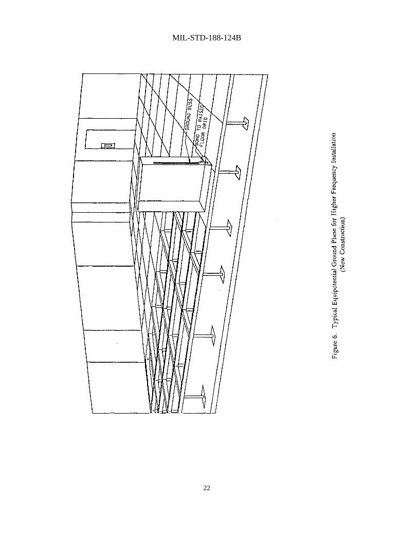
Frequency Installation (New Construction) 22

MIL-STD-188-124B
1
1. SCOPE
1.1 Purpose. This standard establishes the minimum basic requirements and goals for grounding, bonding, and shielding ofground-based telecommunications C-E equipment installations, subsystems, and facilities including buildings and structuressupporting tactical and long haul military communication systems.
1.2 Content. This standard addresses the facilities ground systems, as well as grounding, bonding, and shielding and lightningprotection for telecommunications C-E facilities and equipments. Grounding for building and structures is listed under the headingsof Earth Electrode Subsystem, Fault Protection Subsystem, Lightning Protection Subsystem and Signal Reference Subsystem.
1.3 Applications. This standard shall be used in the design and engineering of new ground-based military communication systems,subsystems, and equipment installations as well as those C-E facilities undergoing major retrofit. This includes air traffic controland navigational aid facilities, radio, radar, satellite ground terminals, telephone central offices, microwave and data communicationssystems, as well as C-E transportables, aircraft simulators, computer centers, and weapon assembly facilities. When upgradingexisting facilities for installation of minor C-E equipments, the requirements of this standard shall be established on a case-by-casebasis by the cognizant engineering agency. Use of this standard for other ground C-E facilities or equipment is also encouraged. Itis not to be used solely as the basis for retrofit of existing C-E facilities. It does not apply to general construction such as barracks,administration buildings, dining facilities, warehouses, and non-communications facilities, nor does it apply to mobile units such astanks, trucks, jeeps, etc.
1.4 Objectives. The objectives of this standard are to provide for the protection of personnel, equipments, buildings and structuresagainst the hazards posed by electrical power faults and lightning strikes. It also provides for the reduction of noise andelectromagnetic interference caused by inadequate grounding, bonding and shielding of ground based military communicationsinstallations to acceptable performance levels. It shall be required that the grounding, bonding, and shielding system be engineeredto be compatible with the supplemental requirements of the specific equipment or facility supporting these communications.
1.5 System Standards and Design Objectives. The parameters and other requirements specified in this document am mandatorysystem standards if the word “shall” is used in connection with the parameter value or requirement under consideration. Non-mandatory design objectives are indicated by parentheses after a standardized parameter value or by the word "should" inconnection with the parameter value or requirement under consideration. For a definition of the terms “system standard” and“design objective” (DO), see FED-STD-1037.

MIL-STD-188-124B
2
2. REFERENCED DOCUMENTS
2.1 Government Documents.
2.1.1 Specifications, Standards, and Handbooks. Unless otherwise specified, the following specifications, standards, andhandbooks of the issue listed in that issue of the Department of Defense Index of Specifications and Standards (DODISS) specifiedin a solicitation form a part of this standard to the extent specified herein.
SPECIFICATIONS
FEDERAL
P-D-680 - Dry Cleaning and Degreasing Solvent
TT-P-1757 - Primer Coating, Zinc Chromate, Low Moisture Sensitivity
STANDARDS
FEDERAL
FED-STD-1037 - Glossary of Telecommunication Terms
FIPS PUB 94 - Guideline on Electrical Power for ADP Installations
MILITARY
AN-735 - Clamp, Loop Type Bonding
AN-742 - Clamp, Loop, Plain, Support, Aircraft
MIL-E-6051D - Electromagnetic Compatibility System Requirements
MIL-STD-285 - Attenuation Measurement for Enclosures, Electromagnetic Shielding, for Electronic Test Purposes, Method of
MIL-STD-454 - Standard General Requirements for Electronic Equipment
MIL-STD-461 - Electromagnetic Emission and Susceptibility Requirements for the Control of Electromagnetic Interference
MIL-STD-462 - Electromagnetic Interference Characteristics, Measurement of
MIL-STD-463 - Definitions and Systems of Units, Electromagnetic Interference and Electromagnetic Compatibility Technology
MIL-STD-1857 - Grounding, Bonding and Shielding Design Practices
MIL-C-83413 - Connectors and Assemblies, Electrical Aircraft Grounding: Type IV Jumper Cable Assembly, Lead, Electrical
MIL-STD-188-125 - High Altitude Electromagnetic Pulse (HEMP) Protection for Ground-Based C41 Facilities
HANDBOOKS

MIL-STD-188-124B
3
MILITARY
MIL-HDBK-232 - Red/Black Engineering Installation Guidelines
MIL-HDBK-419 - Grounding, Bonding, and Shielding for Electronic Equipments and Facilities
MIL-HDBK-1195 - Radio Frequency Shielded Enclosures
FM-1 1-487-4/ - Installation Practices: CommunicationsTO 31-1024 Systems Grounding, Bonding, and Shielding
2.1.2 Other Government Documents, Drawings, and Publications. The following other Government documents, - drawings, andpublications form a part of this standard to the extent specified herein.
DOD Directive 1000.3 - Safety and Occupational Health Policy for the Department of Defense
DOD Directive 3222.3 - Department of Defense Electromagnetic Compatibility Program
(Copies of specifications, standards, handbooks, drawings, and publications required by contractors in connection with specificacquisition functions should be obtained from the contracting activity or as directed by the contracting officer.)
2.2 Other Publications. The following document(s) form a part of this standard to the extent specified herein.The issues of the documents which are indicated as DOD adopted shall be the issue listed in the currentDODISS and the supplement thereto, if applicable.
AMERICAN INSTITUTE OF STEEL CONSTRUCTION (AISC)
AISC S326 - Specification for the Design, Fabrication and Erection of Structural Steel for Buildings
(Application for copies of the AISC specification should be addressed to the American Institute of Steel Construction, 400 NorthMichigan Avenue, Chicago IL 6061 1.)
AMERICAN SOCIETY FOR TESTING AND MATERIALS (ASTM)
ASTM B 32 - Standard Specification for Solder Metal (DOD Adopted)
(Application for the ASTM document should be addressed to the American Society for Testing and Materials, 1916 Race Street,Philadelphia, PA 19103.)

MIL-STD-188-124B
4
AMERICAN WELDING SOCIETY (AWS)
AWS A 5.8 - Specification for Brazing Filler Metal (DOD Adopted, ANSI Approved)
(Application for the AWS specification should be addressed to the American Welding Society, 550 Northwest Lejeune Road, P.O.Box 351040, Miami, Florida 33135.)
NATIONAL FIRE PROTECTION ASSOCIATION (NFPA)
NFPA No. 70 - National Electrical Code
NFPA No. 78 - Lightning Protection Code (ANSI Approved)
(Application for NFPA-70 or 78 should be addressed to the National Fire Protection Association, Batterymarch Park, Quincy MA02269.)
(Industry association specifications and standards are generally available for reference from libraries. They are also distributedamong technical groups and using Federal agencies.)
2.3 Source of Documents. Copies of Federal and military standards, specifications, and associated documents listed in theDepartment of Defense Index of Specifications and Standards (DODISS), should be obtained from the Standardization Order Desk,Bldg 4D, 700 Robbins Avenue, Philadelphia PA 19111-5094. To expedite a customer's ability to obtain a document, acomputerized Telephone Order Entry System (TOES) has been implemented which provides the capability to place an order directlyinto the computer via a touch-tone telephone. This system may also be used to receive immediate status or follow-up on apreviously submitted order. In order to use TOES you must obtain your customer number from previously ordered material. If acustomer number has not been assigned, one can be obtained by calling AC (215) 697-2179 or DSN 442-2179. TOES can then beaccessed by dialing AC (215) 679- 1187 or DSN 442-1187. It is important to replace the letter 'Q' with the number “7” and theletter "Z' with the number “9” since the telephone dial does not include these letters.
Copies of industry association documents should be obtained from the sponsor. Copies of all other listed documents should beobtained from the contracting activity or as directed by the contracting officer.
2.4 Order of Precedence. In the event of a conflict between the text of this standard and the references cited herein, the text of thisstandard shall take precedence.
MIL-STD-188-124B
5
3. DEFINITIONS
For military communications definitions, see FED-STD-1037. Terms related to EMC documents can be found in MIL-STD-463.The following are definitions of acronyms used in the standard.
ADP - Automatic Data Processing
AWG - American Wire Gauge
C-E - Communications-Electronics
DO - Design Objective
EMC - Electromagnetic Compatibility
EMI - Electromagnetic Interference
FIPS - Federal Information Processing Standard
GFCI - Ground Fault Circuit Interrupter
HEMP - High-Altitude Electromagnetic Pulse
NEC - National Electrical Code
NFPA - National Fire Protection Association
TOES - Telephone Order Entry System

MIL-STD-188-124B
6
4. GENERAL REQUIREMENTS
4.1 General. The need exists for effective grounding, bonding, and shielding of (1) electrical/electronic equipments and (2)buildings and structures (facilities) in order to achieve improved equipment operating efficiencies and increased safety practices.These requirements include the reduction of electromagnetic interference (EMI) and noise by the proper grounding, bonding, andshielding of C-E facilities and equipments. This requirement also is intended to protect personnel from hazardous voltages due toelectrical power faults, lightning strikes, and high level electromagnetic radiations associated with normal equipment operation andmaintenance. The facility ground system forms a direct path of known low impedance between earth and the various power andcommunication equipments. This effectively minimizes voltage differentials on the ground plane which exceed a value that willproduce noise or interference to communication circuits. Personnel and equipment protection is afforded when, during anoccurrence of an electrical ground fault, the ground system provides a path for rapid operation of protective overcurrent devices; or,during a lightning strike, provides a low impedance path for current to earth. Personnel and equipment protection against powerfault currents, static charge buildup and lightning flashover shall be provided both by protective ground wires and by bonding allnormally non-current carrying metal objects, including structural steel support members, to the facility ground system. This groundsystem also provides low impedance paths between various buildings and structures of the facility, as well as between equipmentswithin the facility, to earth in order to minimize the effects of noise currents. For additional information refer to the supportingdocument MIL-HDBK-419.
4.2 Grounding.
4.2.1 General. The facility ground system consists of the following electrically interconnected subsystems:
a. The earth electrode subsystem, including the various interconnected metallic elements such as buried fuel tanks, tower bases,fences, water pipes, etc.
b. The fault protection subsystem.
c. The lightning protection subsystem.
d. The signal reference subsystem.
These items, in their entirety, compose the total ground system for the facility (See 5.1 and the Appendix).
4.2.2 Tactical Equipments and Facilities. The grounding, bonding, and shielding requirements for tactical equipments andfacilities are similar in concept to those for fixed C-E facilities. For specific applications, see MIL-HDBK-419 and FM 11-487-4/TO31-10-24.
4.2.3 Grounding in Arctic Regions. See MIL-HDBK-419 for information on ground procedures for arctic conditions.
4.3 Bonding. A bond is an electrical union between two metallic surfaces used to provide a low-impedance path between them.Bonding is the procedure by which the conductive surface of a subassembly or component is electrically connected to another. Thisprevents development of electrical potentials between individual metal surfaces for all frequencies capable of causing interference.(See 5.2).
4.4 Shielding. Shielding is required in electrical and electronic equipments to prevent the equipment from propagating interferenceand to protect the equipment from the effects of interference propagated by other electrical and electronic devices. (See 5.3). Forindividual equipment shielding requirements, see MIL-STD-461 and MIL-STD-1857. Test procedures are provided inMIL-STD-462. If it is determined that additional shielding in the form of a shielded enclosure (screen room) is required, see MIL-STD-285 and MIL-HDBKs-419 and 1195. Facilities requiring HEMP shielding should refer to MIL-STD-188-125.

MIL-STD-188-124B
7

MIL-STD-188-124B
8
5. DETAILED REQUIREMENTS
5.1 Grounding. The facility ground system consists of four electrically connected subsystems. These are:
a. Earth electrode subsystem.
b. Fault protection subsystem.
c. Lightning protection subsystem.
d. Signal reference subsystem.
These subsystems compose the Facility Ground System and are addressed in detail in the following sections.
5.1.1 Building and Structure.
5.1.1.1 Earth Electrode Subsystem.
5.1.1.1.1 General. An earth electrode subsystem shall be installed by the responsible facilities engineering activities at each C-Efacility to provide a low resistance path to earth for lightning and power fault currents and ensure that hazardous voltages do notoccur within the facility. This subsystem shall be capable of dissipating to earth the energy of direct lightning strokes with noensuing degradation to itself. This system shall also interconnect all driven electrodes and underground metal objects of the C-Efacility. The earth electrode subsystem shall not degrade the quality of signals in the signal circuits connected to it. For more detailsregarding installation practices, see MIL-HDBK-419.
5.1.1.1.2 Earth Resistivity Survey. The design agency shall conduct an earth resistivity survey at fixed permanent sites beforefacility design. Survey data shall include all data and information needed for facility grounding design. The survey shall includemeasurement of earth resistivities and recording of features such as type of soil, terrain, rainfall in area streams, man-made featuresimpacting earth resistivity, and similar significant factors.
5.1.1.1.3 Minimum Configuration. The basic earth electrode subsystem configuration shall consist of driven ground rodsuniformly spaced around the facility and placed 0. 6m (2 feet) to 1. 8m (6 feet) outside the drip line of structures. The rods shall beinterconnected with a 1/0 AWG (American Wire Gage) bare copper cable buried at least .45m (1.5 feet) below grade level. Largersize cables as well as greater burial depths shall be specified where earth and atmosphere considerations so dictate. Theinterconnecting cable shall be brazed or welded to each ground rod and shall close on itself to form a complete loop with the endsbrazed or welded together. (See Figures I and 2). Where ground wells are employed, acceptable compression type connectors maybe utilized to bond the cable to the ground rod. Coverage of the earth electrode subsystem by asphalt, concrete, etc. shall bediscouraged and kept to a minimum in an effort to maintain the effectiveness of the subsystem. Refer to MIL-HDBK419 foradditional information.
5.1.1.1.3.1 Resistance to Earth. (DO) The resistance to earth of the earth electrode subsystem should not exceed 10 ohms at fixedpermanent facilities. Resistance to earth for tactical and transportable systems should not exceed the DO established for theparticular system.
5.1.1.1.3.2 Additional Considerations. Where 10 ohms are not obtained at fixed permanent facilities or the required resistanceestablished for tactical or transportable systems due to high soil resistivity, rock formations, or other terrain features, alternatemethods for reducing the resistance to earth shall be considered. For additional information on alternate methods as well as testprocedures, see MIL- HDBK-419.
5.1.1.1.4 Ground Rods.. Ground rods shall be copper-clad steel, a minimum of 3m (10 feet) in length, spaced apart not more thantwice the rod length, and shall not be less than 1.9cm (3/4 inch) in diameter. The thickness of the copper jacket shall not be lessthan 0.3 mm (0.012 inch).

MIL-STD-188-124B
9
5.1.1.1.5 Connecting Risers. Provisions shall be made for bonding the lightning down conductors, the connecting cables requiredby the signal reference and fault protection subsystems, as well as the equipotential plane, and structural steel support members toseparate risers of the earth electrode subsystem.
5.1.1.1.6 Other Underground Metals. Underground metallic pipes entering a facility shall be circumferentially bonded to thebuilding or facility entrance plate whenever such connections are acceptable to both the serving suppliers and the authority havingjurisdiction. The entrance plate shall be bonded to the earth electrode subsystem with two minimum length 1/0 copper cables (seeFigures 3 and 4). The interconnecting cables shall be welded or brazed to the earth electrode subsystem. Adequate corrosionpreventive measures shall be taken. On shielded buildings, the periphery of the entrance plate shall be bonded to the building shield.Structural pilings, tanks, and other large underground metallic masses near the periphery of the structure also shall be bonded in alike manner to the earth electrode subsystem. (See Figures 1 and 2.) Caution shall be used when using clamps to ground metallicgas pipes.

MIL-STD-188-124B
10

MIL-STD-188-124B
11

MIL-STD-188-124B
12

MIL-STD-188-124B
13
MIL-STD-188-124B
14
5.1.1.1.7 Resistance Checks. The resistance to earth of the earth electrode subsystem shall be measured only by the fall ofpotential technique. This shall be accomplished prior to the completion of construction of associated buildings and structures. Toassure adequate performance under all climatic conditions, resistance measurements of the earth electrode subsystem to earth will bemade at three month intervals for 12 months following installation. The test configuration should be recorded and repeated for eachsubsequent measurement. The times of such tests shall be chosen so as to demonstrate the adequacy of the earth electrodesubsystem over expected ranges of local temperature and precipitation. Resistance measurements of the earth electrode subsystemto earth shall be accomplished every 21 months after the initial 12 month period by the facilities engineering activity. For additionaltest information, see MIL-HDBK-419.
5.1.1.2 Fault Protection Subsystem.
5.1.1.2.1 General. The fault protection subsystem consists of a separate grounding conductor (green wire)' to provide personneland equipment protection against power fault currents and static charge buildup. Protection from lightning flashover shall beprovided by grounding all major non-current-carrying metal objects, including main structural steel support members. A ground busshall be provided in all switchboards and panelboards and a separate connecting grounding (green)1 wire shall be carried within thesame raceway or cable with the ac power conductors. The installation shall conform with the requirements of Article 250 of theNational Electrical Code. In all areas required to maintain communication security, equipment and power systems shall begrounded in accordance with MIL-HDBK-419.
5.1.1.2.2 Building Structural Steel. All main metallic structural members (except rebar) such as the building columns, wallframes and roof trusses of steel fame buildings and other metal structures should be made electrically continuous and grounded tothe facility ground system. Whenever vertical rebar is utilized to extend the facility ground system, it shall be made electricallycontinuous and grounded.
5.1.1.2.3 Pipes and Tubes. As required, all metallic piping and tubing and the supports thereof should be electrically continuousand shall be grounded to the facility ground system. See Figures 3 and 4.
5.1.1.2.4 Electrical Supporting Structures. Electrical supporting structures shall be electrically continuous and grounded to thefacility ground system through the fault protection subsystem.
5.1.1.2.4.1 Conduit. All conduit, whether used for power distribution wiring, or for signal and control wiring, shall be grounded inaccordance with the following:
a. All joints between sections of conduit fittings, and busses shall be cleaned in accordance with procedures in 5.2.8 and firmlytightened. The requirement for and use of conductive lubricant between bond members shall be determined by theelectronic/electrical equipment project engineers.
b. Cover plates of conduit fittings, pull boxes, junction boxes, and outlet boxes shall be grounded by securely tightening allavailable screws.
c. Conduit brackets and hangers shall be electrically continuous to the conduit and to the metal structures to which they areattached.
1The grounding conductor (green wire) may be comprised of green, green with yellow stripes, or bare wire with green tape.5.1.1.2.4.2 Cable Trays or Raceways. The individual sections of all metallic cable tray systems shall be bonded to each other andto the raceways which they support. All electrically continuous bonds shall be in accordance with the procedures and requirementsspecified in 5.2 through 5.2.8. Direct bonding methods of 5.2.6 are preferred. All metallic cable tray assemblies shall be connectedto ground within 0.6m (2 feet of each end of the run and at intervals not exceeding 15m (50 feet) along each run.
5.1.1.2.4.3 Wiring System Enclosures. All electrical and electronic wiring and distribution equipment enclosures, not otherwisespecifically covered herein, shall be grounded. The grounding conductor shall not penetrate equipment cabinets or cases but rathershall be terminated on a ground stud peripherally welded to the metal barrier.

MIL-STD-188-124B
15
5.1.1.2.4.4 Metallic Power Cable Sheaths. Metallic cable sheaths on electrical power cables shall be connected to ground at bothends.
5.1.1.2.5 Electrical Power Systems. All electrical power distribution systems shall be grounded in accordance with the following:
5.1.1.2.5.1 AC Distribution Systems. AC power distribution systems shall have the neutral conductor grounded at the distributiontransformer and to the earth electrode subsystem of the facility. The size of the ground conductor from the first service disconnectmeans to the earth electrode subsystem shall be as specified in Table 1-20 of MIL-HDBK-419 or Table 250-94 of the NationalElectrical Code. In each facility served by a common distribution transformer, the neutral shall be directly connected to the nearestpoint of the earth electrode subsystem. Where delta-wye system conversion is employed, the service entrance shall be a five-wiresystem consisting of three phase conductors, a grounded (neutral) conductor, and a grounding (green) conductor. In each facility,all power distribution neutrals shall be isolated from the C-E equipment case and the structure elements so that no ac return currentflows through the equipment and fault protection subsystem or the signal reference network. The fault protection subsystemgrounding (green) conductor shall be installed in accordance with the National Electrical Code for all C-E equipment. Conduit shallnot be used in lieu of the separate grounding (green) wire.
5.1.1.2.5.1.1 Single Building with Multiple Power Sources. All grounded (neutral) conductors shall be grounded at the firstservice disconnect means of each source. For delta-wye conversions, a five-wire system shall be utilized from each source. Deltasystems shall employ four-wires from the source, consisting of three phase conductors and a grounded conductor for groundingpurposes.
5.1.1.2.5.1.2 Multiple Buildings with Single Power Source. Neutral conductors from multiple buildings being serviced from asingle commercial power source shall be grounded at the source only. The neutral shall be isolated at the first disconnect means. Afive-wire system shall be utilized from the source.
5.1.1.2.5.2 Standby AC Generators. Motor and generator frames and housings shall be grounded in accordance with Article 250of the National Electrical Code. The generator neutral shall be grounded directly to the earth electrode subsystem. Whengenerators are connected in parallel, the neutrals shall be interconnected and grounded with a single ground conductor.
5.1.1.2.5.3 AC Outlets. Grounding of receptacles and associated grounding terminals shall meet the requirements of Articles 250-74 and 250-94 of the National Electrical Code (1984 or later). However, aluminum and copper clad aluminum conductorspermitted by Article 250-94 shall not be used. When necessary to control noise problems, grounding of grounding terminals may beaccomplished IAW Exception 4 of Article 25004. Grounding of metallic outlet boxes shall not be dependent upon serrated strips orclips.
5.1.1.2.5.4 Electrical Motors and Generators. The frames of motors, generators, and other types of electrical rotating machineryshall be grounded to the fault protection subsystem, according to Article 430 of the National Electrical Code.
5.1.1.2.5.5 DC Power Sources. One leg of each dc power system shall be grounded with a single connection directly to the earthelectrode subsystem. The size of the grounding conductor shall be as specified by Article 250 of the National Electrical Code.Whether grounded at the source or at a load, a separate current return from load to the source shall be used to assure that no dccurrent flows in the fault protection or the signal reference subsystem.
5.1.1.2.5.6 Metallic Battery Racks. Metallic battery racks shall also be grounded to the facility ground system at the nearest point.
5.1.1.2.5.7 Ground Fault Circuit Interrupters. All 120 volt single phase 15 and 20 ampere receptacle outlets shall use ground faultcircuit interrupters (GFCI) for personnel protection (See NEC Article 210 and 215).
5.1.1.2.6 Secure Facilities. All areas required to maintain communications security equipment and associated power systems shallbe grounded in accordance with MIL-HDBK-419.
5.1.1.3 Lightning Protection Subsystem.
5.1.1.3.1 General. Lightning protection shall be provided as required for buildings and structures in accordance with the NationalFire Protection Association (NFPA) No. 78, and the following:
MIL-STD-188-124B
16
5.1.1.3.2 Buildings and Structures. Lightning protection shall be provided as required for buildings and structures in accordancewith the additions and modifications specified herein and the applicable paragraphs of NFPA No. 78. This protection shall beextended to all electrical, electronic, or other elements which are a part of, or are in support of all C-E facilities. Such elements shallinclude, but shall not be limited to, substations (to the extent that additional protection beyond that provided by the electric utility isnecessary), power poles, towers, antennas, masts, etc.

MIL-STD-188-124B
17
5.1.1.3.3 Down Conductors. Where copper-clad steel down conductors are used on structures not greater than 23m (75 feet) inheight, the dc resistance of solid wires or stranded cables shall not be greater than 0. 176 ohms per 305m (1000 feet). On structuresgreater than 23m (75 feet) in height, the dc resistance of the wire or cable shall not be greater than 0.088 ohms per 305m (1000feet). The size of wires in copper-clad stranded cable shall not be less than No. 14 AWG. (In cases where mechanical andinstallation situations warrant, a larger (preferably No. 6 AWG copper) wire may be utilized.) The copper covering of all copper-cladsteel down conductors shall be permanently and effectively welded to the steel core. The conductivity of copper- clad conductorsshall not be less than 30 % of a solid copper conductor of equivalent cross-sectional area. Down conductors bends shall be gradualand not have a radius less than 20cm (8 in). The angle of any bend shall not be less than 90 degrees (see Figure 5). Any metalobject within 1.8m (6 feet of the lightning download shall be bonded to the down conductor (see NEC Article 250). Wherepracticable, a separation of at least 1.8m (6 feet) shall be maintained between open conductors of power and communicationssystems and lightning down conductors (see NEC Article 800). On structures higher than 18m (60 feet) there shall be at least oneadditional down conductor for each additional 18m (60 feet) of height fractions thereof, except that the interval between downconductors around the perimeters shall not be less than 15m (50 feet) nor greater than 30m (100 feet). Down conductors shall becontinuous and shall be bonded in accordance with 5.1.1.1.5 and 5.2.3 to an earth electrode subsystem or to a ground rod bonded tothis subsystem installed as near as practicable and within1.8m (6 feet) from the structure.
5.1.1.3.4 Bonding,. All bonds between elements of the lightning protection subsystems shall be made by welding or brazing or ULapproved high compression clamping devices. Welding or brazing shall be used for all bonds not readily accessible for inspectionand maintenance. Soft solder shall not be used for bonding any conductor in the lightning protection subsystem.
5.1.1.3.5 Structural Steel. Substantial metal structural elements of buildings and towers (including overall building shield whereit exists) shall be acceptable substitutes for lightning down conductors provided they are permanently bonded in accordance with5.2 and bonded to the earth electrode subsystem. Bonding straps acrossall structural joints shall be IAW 5.2.3.3.1.
5.1.1.3.6 Air Terminals (Lightning Rods). Non-metallic objects, extensions, or protrusions requiring protection shall have the airterminals designed and installed in accordance with requirements of NFPA No. 78, chapters 3-9 and 3-10.
MIL-STD-188-124B
18
5.1.1.3.7 Guards. Where conductive guards must be used, the guards shall be electrically bonded at each end of the enclosedlightning conductor. Each isolated section of conductive guards shall also be bonded to the lightning conductor.
5.1.1.3.8 Supporting Structures. Lightning protection shall be provided for radar, communications or navigational aid antennatowers, and similar supporting structures in accordance with the following:
5.1.1.3.8.1 Earth Electrode Subsystem. An earth electrode subsystem conforming to requirements 5.1.1 through 5.1.1.1.7 shall beprovided for all supporting structures. If a tower is adjacent to another structure such that the minimum distance between the towerand the structure is 6m (20 feet) or less, one earth electrode subsystem encompassing both the tower and the other structure shall beprovided.For distances greater than 6m (20 feet), separate earth electrode subsystems shall be installed. These subsystems shall beinterconnected for separations up to 200 feet. Two bare 1/0 AWG copper cables shall be used by independent routes to bond theearth electrode subsystem of the tower to the earth electrode subsystem of buildings and structures that have signal, control, orpower line interfaces with the tower and are separated less than 60m (200 feet). (See Figures 1 and 2).
5.1.1.3.8.2 Air Terminal. An air terminal shall be installed on the tower as specified in 5.1.1.3.6. A minimum of two conductivepaths shall exist between any two air terminals and between any air terminal and the earth electrode subsystem (except for dead endsless than 5m (16 feet)).
5.1.1.3.8.3 Antennas. Antennas installed on towers or platforms shall be within a 1:1 zone of protection of an air terminal. Largearray type antennas such as rhombics, yagis, etc. shall be protected by 0.6m (2 feet) air terminals installed on the top of the mast orstructure supporting the antenna. For additional information see MIL-HDBK-419.
5.1.1.3.8.4 Down Conductors. As a minimum, down conductors shall meet the requirements of 5.1.1.3.3. Each down conductorshall be continuous and shall be bonded to the earth electrode subsystem for the tower in accordance with 5.2. For metal towers,where the structural elements are not used as down conductors, the down conductors shall be bonded to the tower legs at the base.Down conductors connecting cables to the earth electrode subsystem shall be protected against mechanical damage. Connectingcables passing through foundations or footings shall be installed in plastic or non-metallic conduit.
5.1.1.3.8.5 Waveguide grounding. As a minimum, all waveguides shall be grounded as follows:
a. All waveguides to the antennas shall be grounded at three points: near the antenna, at the vertical-tohorizontal transition nearthe base of the tower, and at the waveguide entry port.
b. Metallic supporting structures for waveguides shall be electrically continuous and shall be connected to the exterior earthelectrode subsystem at the first and last support columns as a minimum. The wire leads shall be as direct as possible.
c. Waveguides shall be grounded with solid copper strap or copper wire at least equal to No. 6 AWG. The size of wires inthis cable shall not be less than No. 14 AWG. Braid or finer-stranded wire than No. 14 AWG shall not be used. All bends ofground conductors shall have a radius of 20cm (8 in) or greater and the angle of any bend shall not be less than 90 degrees.
d. Waveguides shall be properly bonded to the waveguide entrance panel and the panel shall be connected by the most directroute to the earth electrode subsystem using a 1/0 stranded copper cable. For additional information see MIL-HDBK-419.
5.1.1.3.8.6 Coaxial Cable Grounding,. Coaxial cables shall be bonded to the building or facility entrance plate and in turn to theearth electrode subsystem. For additional information see MIL-HDBK-419.
5.1.1.3.9 Exterior Nonstructural Metal Elements. All exterior hand rails, ladders, stairways, antenna pedestals, and antennaelements operating at ground potential shall be bonded to the lightning protection subsystem with a No. 6 AWG copper wire orlarger.
5.1.1.3.10 Exterior Wires and Cables
5.1.1.3.10.1 Conduit. Corrosion-protected steel conduit shall be used to completely enclose susceptible wiring

MIL-STD-188-124B
19
(notably outdoor or underground signal wiring not otherwise protected) to shield against lightning or lightning induced currents andvoltages. Such conduit shall be electrically bonded from section to section with corrosionprotected compression fittings or shall bewelded or brazed at each joint. Pull boxes, junction boxes, etc. that are integral to the conduit and electrically bonded to the conduitshall be regarded as conduit. Metal manholes, where used, shall be bonded to the conduit. Non-metallic manholes shall be bridgedto provide a continuous electrical path from one section of conduit to other sections of conduit entering or leaving a manhole. Theconduit shall be bonded at each end to the earth electrode subsystem of each terminating facility.
5.1.1.3.10.2 Overhead Guard Wires. Overhead guard wires shall be regarded as air terminals. Such wires shall be spaced not lessthan 1m (3 feet) above any signal or control circuits being protected. The minimum conductor size shall be 1/0 AWG galvanizedsteel. Overhead guard wires shall be grounded to the earth electrode subsystem of each terminating facility. When the distancebetween terminating facilities exceeds 76m (250 feet), the guard wires shall also be bonded to a ground rod meeting therequirements of 5.1.1.1.4 at intervals not exceeding 76m (250 feet). The top of the ground rod shall not be less than 0.3m (1 foot)below grade level.
5.1.1.3.11 Underground Guard Wires. Buried signal, power, or control wires or cables not otherwise protected by ferrous conduitin the manner prescribed by 5.1.1.3.10.1 shall be protected by a bare I/O AWG copper guard wire embedded in the soil above andparallel to the wires, cables or ducts. The guard wire shall be laid a minimum of 45cm (18 in) below grade level and at least 25cm(10 in) above the duct or uppermost wire or cable. Where the width of the duct or the spread of the cable run does not exceed 1m(3 feet), one guard wire centered over the duct or cable run shall be installed. Where the spread exceeds lm (3 feet), two guardwires shall be used. They shall be spaced at least 30cm (12 in) apart and not less than 30cm (12 in) nor more than 46cm (18 in)inside the outermost wires or the edges of the duct bank. All guard wires shall be bonded at each end to the earth electrodesubsystem of each terminating facility. The requirement and need for underground guard wires shall be determined by theelectronic/electrical equipmentproject engineer and the facilities engineering activity and shall be determined on a case and location basis dependent upon thepriority of the circuit and the degree of lightning anticipated.
5.1.1.3.12 Lightning Arrestors. Exposed and underground power lines, not otherwise protected, shall be provided with ULapproved lightning arrestors at the point of entrance into the facility. The arrestors shall be installed in accordance with Article 280of the National Electrical Code and MIL-HDBK-419. (If a conflict should occur between the NEC and the handbook, the morestringent should apply.)
MIL-STD-188-124B
20
5.1.1.3.13. Security/Perimeter Fences All security or perimeter fence shall be grounded IAW procedures outlined in MIL-HDBK-419.
5.1.1.4 Signal Reference Subsystem.
5.1.1.4.1 General. A signal reference subsystem shall be installed at each facility to control static charges and noise, and establish acommon reference for signals between sources and loads. The desired goal is toaccomplish grounding functions in a manner that minimizes interference between equipments. Where units aredistributed throughout the facility, the signal reference ground subsystem should consist of an equipotential ground plane.
5.1.1.4.2 Higher Frequency Network. Higher frequency networks may require an equipotential plane. The equipotential planeshall be a solid sheet or may consist of a wire mesh. A mesh will appear electrically as a solid sheet as long as the mesh openings are1/8 lambda or less at the highest frequencies of concern. When it is not feasible to install a fine mesh to meet the 1/8 lambdacriterion, a larger grid may installed, but in no case shall the mesh size be greater than 4 inches. The equipotential plane, if required,should be installed under the equipment, but for retrofit may be installed overhead (see Figures 1, 2, and 6.) Signal, control, andpower cables should be routed in close proximity to the equipotential ground plane with the signal and control cables separated frompower cables as far as practicable. The equipotential plane shall be connected to the building structure shell and earth electrodesubsystem at as many points as practical. For additional information see the Appendix and MIL-HDBK-419.
5.1.1.4.3 Lower Frequency Network. A lower frequency network will be installed at facilities employing lower frequencyequipments from dc to 30 Khz, and in some cases to 300 Khz. The purpose of this network is to isolate lower frequency signalsfrom all other ground networks including structural, safety, lightning and power grounds. This network prevents stray currents(primarily 60 Hz) from developing voltage potentials between points on the ground network. This lower frequency network mustbe connected to the earth electrode subsystem at one point only (single point) and must be configured to minimize conductor pathlength. Additional information on lower frequency networks can be obtained from MIL-HDBK-419.
5.1.2 Communications-Electronics (C-E) Equipment.
5.1.2.1 Signal Reference Subsystem. This subsystem provides the voltage reference point(s) for all signal grounding.
5.1.2.1.1 Higher Frequency Network. The higher frequency (equipotential) network provides an equipotential plane with theminimum impedance between the associated electronic components, racks, frames, etc. To the extent permitted by circuit designrequirements, all reference points and planes shall be directly grounded to the chassis and the equipment case. Direct grounding ispreferred; however, where individual circuit subassemblies must be floated at a dc potential, capacitive grounding is acceptable.Where mounted in a rack, cabinet or enclosure, the equipment case shall be bonded to the rack, cabinet or enclosure, in accordancewith 5.2.4. To minimize the voltage differential between points in the higher frequency signal reference network, the dc resistancebetween any two points within a chassis or equipment cabinet serving as a reference for higher frequency signals shall be less than 1milliohm (0.001 ohm). The grounding conductor shall not penetrate equipment cabinets or cases but rather shall be terminated onthe ground stud peripherally welded to the metal barrier.
5.1.2.1.1.1 Signal Isolation. There shall be no isolation between equipment chassis and case for higher frequency equipmentsexcept where stated in 5.1.2. 1. 1.
5.1.2.1.1.2 Equipment Signal Ground Terminations. Each individual unit or piece of equipment shall either be bonded to its rackor cabinet in accordance with 5.2.4 or shall have its case or chassis bonded to the nearest point of the equipotential plane. Racksand cabinets shall also be grounded to the equipotential plane with a copper strap. All equipment cases and all racks and cabinetsshallhave a grounding terminal as long as it permits convenient and secure attachment of the ground strap.
5.1.2.1.1.3 Shield Terminations of Coaxial and Other Higher Frequency Cables. All connectors shall be of a type and design thatprovide a low impedance path from the signal line shield to the equipment case. If the signal circuit must be isolated from theequipment case, and if the shielding effectiveness of the case must not be degraded, a connector of a triaxial design that properlygrounds the outer cable shield to the case shall be used. Shields of coaxial cables and shielded balanced transmission lines shall beterminated by peripherally grounding the shield to the equipment case. Bonding of connectors shall be in accordance with 5.2.5.Coaxial shields and connector shells shall be grounded at junction boxes, patch panels, signal distribution boxes and otherinterconnection points along the signal path.

MIL-STD-188-124B
21
NOTE: Signal and control cables should be separated from power cables as far as practicable.
5.1.2.1.1.4 Overall Shields. Shields surrounding a cable containing individually shielded lower frequency signal lines or containingonly unshielded lines shall be grounded at each end and at junction boxes, patch panels, distribution points and at other intermediatepoints along the cable run. Overall shields shall be grounded to cases, cabinets or conducting surfaces.
MIL-STD-188-124B
22

MIL-STD-188-124B
23
5.1.2.2 Fault Protection Subsystem.
5.1.2.2.1 General. The fault protection subsystem ensures that personnel are protected from shock hazard and the equipment isprotected from damage resulting from faults, including short circuits that may develop in the electrical supply and distributionsystems. The ac power neutral is isolated from this subsystem throughout the facility except for one point of interface at the powerservice entry. (See 5.1.1.2).
5.1.2.2.2 Personnel Protection. Means shall be provided by which the equipment parts such as panels, covers, knobs, switches,and connectors that are subject to human contact during normal operation and maintenance are grounded to prevent them frombecoming electrically energized in case of power line faults or component failures. All contacts, terminals and like devices havingdangerous voltages shall be guarded from accidental contact by personnel if such points are exposed to contact during direct supportor operator maintenance. Ground Fault Circuit Interrupters (GFCI), installed on convenience outlets as specified by 5.1.1.2.5.7 orthe National Electric Code Article 215, should be utilized.
5.1.2.2.3 AC Power Neutral. In all electrical and electronic equipment, the ac power neutral (white wire) shall be insulated fromthe equipment chassis, case, and facility ground system except for one point at the facility power service entry. With the circuitbreaker open and the neutral disconnected, a minimum of 1 megohm dc resistance shall exist between either side of the ac line andthe equipment case (ground).
5.1.2.2.4 Individual Power Line Filters. All power line filter cases shall be directly bonded in accordance with5.2 to the equipment case or enclosure.
5.1.2.2.5 Convenience Outlets. Where AC outlets are provided with equipment of equipment cabinets, they shall be installed IAWthe requirements of Articles 25&74 and 250-94 of the National Electrical Code (1984 or later). However, aluminum and copperclad aluminum conductors permitted by Article 250-94 shall not be used. As these outlets are immediately associated withequipment installed in racks or cabinets, they shall not be used for powering any external equipment except that used formaintenance and testing of equipment in the cabinet or racks.
5.1.2.2.6 Portable Equipment. Portable electrical or electronic equipment cases, enclosures, and housings shall be considered to beadequately grounded for personnel protection through the third wire (grounding) of the power cord provided that continuity is firmlyestablished between the case, enclosure, or housing and the receptacle’s ground terminal. The third wire of the power cord shall notbe used for signal ground.
MIL-STD-188-124B
24
5.2 Bonding. (For Building, Structures, and C-E Equipment Installations).
5.2.1 General. Bonding refers to the process by which a low impedance path for the flow of an electric current is establishedbetween two metallic objects. In any realistic electronic facility, whether it is only one piece of equipment or an entire facility,numerous interconnections between metallic objects must be made in order to minimize electric shock hazards, provide lightningprotection, establish references for electronic signals, etc. Ideally, each of these interconnections should be made so that themechanical and electrical properties of the path are determined by the connected members and not by the interconnectionjunction. Further, me joint must maintain its properties over an extended period of time in order to prevent progressive degradationfrom subsequent deterioration through corrosion or mechanical looseness. In terms of the results to be achieved, bonding isnecessary for the following reasons:
a. Protection of equipment and personnel from the hazards of lightning discharges.
b. Establishment of fault current return paths.
c. Establishment of homogeneous and stable paths for electrical currents.
d. Minimization of voltage on enclosures and housings.
e. Protection of personnel from shock hazards.
f. Prevention of static charge accumulation.
5.2.2 Surface Platings or Treatments. Surface treatments, including the platings provided for added durabilityor corrosion protection, shall offer high conductivity. Plating metals shall be electrochemically compatible with the base metals.Unless suitably protected from the atmosphere, silver and other easily tarnished metals shall not be used to plate the bond surfaces.
5.2.3 Bond Protection. All bonds except those listed in 5.2.3.2 shall be suitably protected against weather, corrosive atmospheres,vibrations and mechanical damage. Under dry conditions, a corrosion preventive or sealant shall be applied within 24 hours ofassembly of the bond materials. Under high humidity conditions, sealing of the bond shall be accomplished within one hour ofjoining.
5.2.3.1 Corrosion Protection. Each bonded joint shall be protected against corrosion by assuring that the metals to be bonded aregalvanically compatible. Bonds shall be painted with a moisture proof paint conforming to the requirements of Federal SpecificationTT-P-1757 or shall be sealed with a silicone or petroleum-based sealant to prevent moisture from reaching the bond area. Bondswhich are located in areas not reasonably accessible for maintenance shall be sealed with permanent waterproof compounds.Anodized or other similarly protected bonds shall not require painting to meet the requirements of this standard.
5.2.3.2 Compression Bonds in Protected Areas. Compression bonds between copper conductors or between compatible aluminumalloys and located in readily accessible areas not subject to weather exposure, corrosive fumes or excessive dust shall not requiresealing. This is subject to the approval of the responsible facilities engineering activity or the local authorized approvalrepresentative.
5.2.3.3 Vibration. Bonds shall be protected from vibration-induced deterioration by assuring that bolts and screws are adequatelytorqued.
5.2.3.3.1 Bonding Strap. Bonding straps installed across shock mounts or other suspension or support devices shall not impedethe performance of the mounting device. They shall be capable of withstanding the anticipated motion and vibrational requirementswithout suffering metal fatigue or other means of failure. Extra care should be utilized in the attachment of the ends of bondingstraps to prevent arcing or other means of electrical noise generation with movement of the strap. NOTE: Bonding straps with awidth-to-length ratio approximately 1-to-5 and thickness of approximately 0.76 mm (0.030 in) are better than wires, due to lowerinductance per unit length.
5.2.4 Bond Resistance. All bonds for ground conductors whose primary function is to provide a path forpower, control or signal currents, and lightning protection shall have a maximum dc resistance of 1 milliohm(0.001 ohm). The resistance across joints or seams in metallic members required to provide electromagnetic

MIL-STD-188-124B
25
shielding shall also be 1 milliohm or less.
5.2.5 Materials. Unless otherwise specified, bonding materials shall be in accordance with 5.2.5.1 through5.2.6.6.
5.2.5.1 Sweat Solder. Solder used for sweat soldering shall conform to ASTM B 32.
5.2.5.2 Brazing Solder. Brazing solder shall conform to AWS A5.8.
5.2.5.3 Clamps. Where bonding clamps are not avoidable, they shall conform to AN735 or AN742.
5.2.5.4 Nuts, Bolts and Washers. Nuts and bolts shall be adequately torqued. Flat washers shall not besurface treated; they shall be plated as specified in 5.2.9 for corrosion control purposes. Star washers smaller than 1.3cm (1/2 in)shall not be used.
5.2.6 Direct Bonds. Wherever possible, the bonding of metallic members to be interconnected shall be accomplished by directcontact of the mating surface without the use of an auxiliary conductor. Electrical continuity is obtained by establishing a fusedmetal bridge across the junction by welding, brazing, or soldering, or by maintaining a high pressure contact between the matingsurfaces with bolts.
MIL-STD-188-124B
26
5.2.6.1 Welding. Permanent connections between ferrous materials shall be welded whenever required. Welds of sufficient extentto support the load demands on the bonded members shall be considered to provide an adequate electrical bond when the followingconditions are met:
a. On members whose maximum dimension is 5cm (2 in) or less, the weld shall extend completely across the side or surface oflargest dimension.
b. On members whose largest dimension is greater than 5cm (2 in) but less than 30cm (12 in), one weld of at least 5cm (2 in)in length shall be provided.
c. On members whose largest dimension is greater than 30cm (12 in), two or more welds, each not less than 5cm (2 in) inlength, shall be uniformly spaced across the surface of largest dimension. The maximum spacing between successive welds shallnot exceed 30cm (12 in).
d. At butt joints, complete penetration welds shall be used on all members whose thickness is 0.6cm (1/4 in) or less. Wherethe thickness of the members is greater than 0.6cm (1/4 in), the depth of the weld shall not be less than 0.6cm (1/4 in).
e. A fillet weld shall have an effective size equal to thethickness of the members or as specified by AISC Specification S326.
f. At lap joints between members whose thickness is less than 0. 6cm (I /4 in), double fillet welds shall be provided.
5.2.6.2 Brazing and Silver Soldering. Brazing or silver soldering shall be acceptable for the permanentbonding of copper and copper alloy materials.
5.2.6.3 Bonding of Copper to Steel. Either brazing or exothermic welding shall be used for the permanentbonding of copper conductors to steel or other ferrous structural members.
5.2.6.4 Soft Soldering. Soft soldering shall not be used for bonding purposes unless:
a. The joint is not subject to mechanical loads and stresses.
b. The conducting path is not subject to lightning or power fault currents.
5.2.6.4.1 Sweat Soldering. Sweat soldering shall not be used for electrical bonding unless other fasteners such as bolts or rivets areconcurrently used to provide mechanical strength, and the requirement of 5.2.6.4 above is met.
5.2.6.4.2 Sheet Metal or Duct Work. Where required, non-current carrying members such as air conditioning and heating ducts,gutter spouts, canopies, awnings, screens, etc., normally held in place or supported with sheet metal screws or mated mechanicaljoints shall be bonded by soft soldering.
5.2.6.5 Bolting. All bonds utilizing bolts and other threaded fasteners shall be adequately torqued. Inspection shall be conductedperiodically. Before joining, all faying surfaces shall be cleaned in accordance with 5.2.8 through 5.2.8.4. Particular care shall betaken to provide adequate corrosion protection to all electrical bonds made with bolts and other threaded fasteners.
MIL-STD-188-124B
27
5.2.6.6 C-Clamps and Spring Clamps. C-Clamps and spring clamps shall not be used for permanent or semipermanent bonding.
5.2.7 Indirect Bonds. Where the direct joining of structural elements, equipments, and electrical paths is impossible orimpracticable to achieve, bonding straps or jumpers meeting the requirements of 5.2.3.3.1 shall be used. If additional informationis required, see MIL-HDBK-419.
5.2.8 Surface Preparation. All mating surfaces which comprise the bond shall be thoroughly cleaned before joining to removedust, grease, oil, moisture, nonconductive protective finishes, and corrosion products.
5.2.8.1 Area to be Cleaned. All bonding surfaces shall be cleaned over an area that extends at least 0.6cm (1/4 in) beyond allsides of the bonded area on the larger member.
5.2.8.2 Paint Removal. Paint, primers, and other organic finishes shall be removed from the metal.
5.2.8.3 Inorganic Film Removal. Rust, oxides, and nonconductive surface finishes such as anodize shall be removed.
5.2.8.4 Final Cleaning. After initial cleaning with chemical paint removers or mechanical abrasives, the bare metal shall be wipedor brushed with dry cleaning solvent meeting the requirements of Federal Specification P-D-680. Surfaces not requiring the useof mechanical abrasives or chemical paint removers shall be cleaned with a dry cleaning solvent to remove grease, oil, corrosionpreventives, dust, dirt, and moisture prior to bonding.
5.2.8.4.1 Clad Metals. Clad metals shall be cleaned with fine steel wool or grit in such a manner that the cladding material is notpenetrated by the cleaning process. A bright, smooth surface shall be achieved. The cleaned area shall be wiped with dry cleaningsolvent and allowed to air dry before completing the bond.
5.2.8.4.2 Aluminum Alloy. After cleaning aluminum surfaces to a bright finish, a brush coating of anodize or other similarconductive coating shall be applied to the mating surface.
5.2.8.5 Completion of the Bond. If an intentional protective coating is removed from the metal surface, the mating surfaces shallbe joined within 30 minutes after cleaning.
5.2.9 Dissimilar Metals. All mating surface materials that comprise a bond shall be identified. Compression bonding with the useof bolts or clamps shall be utilized only between metals having acceptable coupling values. When the base metals form couples thatare not allowed, the metals shall be plated, coated, or otherwise protected with a conductive finish, or a material compatible witheach shall be inserted between the two base metals. It shall be constructed from, or plated with, an appropriate intermediate metal.
5.2.9.1 Corrosion Prevention. Because of galvanic corrosion between dissimilar metals, the welded or brazed joint shall becovered with pitch or other suitable waterproof compound.
5.2.10 Enclosure Bonding. Subassemblies and equipment shall be directly bonded, whenever practical, at the areas of physicalcontact with the mounting-surface.
5.2.10.1 Subassemblies. Subassemblies shall be bonded to the chassis utilizing the maximum possible contact area. All feed-throughs, filters, and connectors shall be bonded to the subassembly enclosure to maintain shield effectiveness. Interferencesuppression covers shall exhibit intimate contact around their periphery; such contactshall be achieved and maintained through the use of closely spaced screws or bolts, or by the use of resilient gaskets, or both.
5.2.10.2 Equipments. The chassis or case of an equipment shall be directly bonded to the rack, frame, or cabinet in which it ismounted and in accordance with the intended purpose of the grounding methods as specified within this standard. Adjacentcabinets and racks shall be bonded to each other. Flange surfaces and the contact surface on the supporting element shall be cleanedof all paint or other insulating substances in accordance with the requirements of 5.2.8 through 5.2.8.4. Fasteners shall maintainsufficient pressure to assure adequate surface contact to meet the bond resistance requirements of 5.2.4. Tinnerman nuts and sheetmetal screws shall not be used for fasteners. If the equipment must remain operational when partially or completely withdrawn
MIL-STD-188-124B
28
from its mounted position, the bond shall be maintained by a moving area of contact or by the use of a flexible bonding strap.Flexible straps shall be permitted only where necessary to maintain bonding during adjustments or maintenance or when otherconstraints prevent direct bonding. The grounding conductor shall not penetrate equipment cabinets or cases but rather shall beterminated on the ground stud peripherally welded to the metal barrier.
5.2.11 Connector Mounting. Standard MS-type connectors as well as other shell-type connectors and coaxial connectors shall bemounted so that intimate metallic contact is maintained with the panel on which mounted. Bonding shall be accomplishedcompletely around the periphery of the flange of the connector. Both the flange surface and the mating area of the panel shall becleaned in accordance with 5.2.8 through 5.2.8.4. After mounting of the connector, the exposed area of the panel shall be repaintedor otherwise protected from corrosion in accordance with 5.2.3. 1.
5.2.12 Shield Terminations. Cable shields shall be terminated in the manner specified in 5.1.2.1.1.3 and5.1.2.1.1.4 and tightly fastened to the cable connector shell with a compression or soldered connection. The cable shall be able towithstand the anticipated use without becoming noisy or suffering degradation in shielding efficiency. Coaxial connectors shall beof a material that is corrosion resistant in accordance with requirement 10 of MIL-STD-454. Shield connections for cables usingconnectors shall be kept to less than 2.5cm (1 in) from the point of breakaway from the shielded conductors of the cable. Foilshields are not acceptable for peripheral bonding and do not provide mechanical durability.
5.2.13 RF Gaskets. Conductive gaskets shall be made of corrosion resistant material, shall meet the resistance requirements of5.2.4 and shall possess strength, resiliency, and hardness to maintain the shielding effectiveness of the bond. The surfaces ofcontact with the gasket shall be smooth and free of oily films, corrosion, moisture, and paint. The gasket shall be firmly affixed toone of the bond surfaces by screws, conductive cement, or other means which do not interfere with the effectiveness of the gasket.The gaskets may be placed in a milled slot to prevent lateral movement when the bond is disassembled. Gaskets shall be aminimum of 3mm (1/8 in) wide.The gasket as well as the contact surfaces, shall be protected from corrosion.
MIL-STD-188-124B
29
5.3 Shielding.
5.3.1 General. Groups of equipment or subsystems may be made electromagnetically compatible by any combination of threefundamental approaches: (1) the interfering signal level may be reduced, (2) the receptor susceptibility may be reduced, or (3) theattenuation of the path or paths over which interference is transmitted from source to receptor may be increased. Radiatedinterference signals generated by electromagnetic fields may be effectively attenuated by electromagnetic shielding, either at thesource or at the receptor. Shielding, when properly designed and implemented, offers significant wideband protection againstelectromagnetic radiation, where source and receptor are not sufficiently separated for adequate free space radiation attenuation.It is relatively easy to obtain 40 dB of shielding effectiveness in a frequency range above 100 Khz with a single shield, and values ashigh as 70 dB can be obtained with careful single-shield construction. Where this is inadequate, double shields are normally used,providing shielding values as high as 120 dB. Radiated energy may still be coupled into a susceptible device through a shield ofinadequate thickness, through holes penetrated for ventilation and other purposes, and through imperfectly jointed shielded sections.Precise calculation of shielding effectiveness, even for perfectly joined solid shields, depends on the form of the shield and the typeof field for which the shielding is to be used. Both electric and magnetic coupling can occur. Normally, it is relatively easy toprovide electric shielding. Magnetic shielding, however, is more difficult to provide, particularly at frequencies below 100 Khz.
5.3.1.1 Basic Shielding Requirements. The C-E equipment shall meet the applicable electromagnetic susceptibility and emissionrequirements of MIL-STD-461. Additionally, where required, the equipment shall incorporate shields required to protect personnelfrom high level electromagnetic fields and X-rays which may be intentionally or unintentionally generated by the equipment.
5.3.1.2 Shielded Enclosures. Shielded enclosures shall only be specified when the power densities of nearby transmitters exceedthe susceptibility levels of the C-E equipments programmed for installation.
5.3.2 Electromagnetic Interference (EMI) Control. Shielding shall be integrated with other basic interference control measuressuch as filtering, wire routing, cable and circuit layout, signal processing, spectrum control, and frequency assignment to achieveoperational compatibility of the equipment. The degree of shielding shall be determined by the systems engineering process.
5.3.2.1 Materials. Shields shall be constructed from material that provides the required degree of signal suppression withoutincurring unnecessary expense and weight. The selection of materials shall be based upon the following: the amplitude andfrequency of the signals to be attenuated, the characteristics of the electromagnetic field of the signal (i.e., is the signal being coupledvia inductive, capacitive, or free space means), configuration, the installation constraints, and the corrosion properties.
5.3.2.2 Gaskets. Conductive gaskets conforming to 5.2.13 shall be utilized at joints, seams, access covers, removable partitions,and other shield discontinuities to the extent necessary to provide interference-free operation of the equipment under normal use andenvironmental conditions. Finger stock used on doors, covers, or other closures subject to frequent openings shall be installed in amanner that permits easy cleaning and repair.
5.3.2.3 Filter Integration. Filters on power, control, and signal lines shall be installed in a manner that maintains the integrity ofthe shield. Power line filters shall be completely shielded with the filter case grounded in accordance with 5.2.10. Filters on powercontrol and signal lines shall be placed as close as possible to the point of penetration of the case in order to avoid long, unprotectedpaths inside the equipment.
5.3.2.4 Control of Apertures. Unnecessary apertures shall be avoided. Only those shield openings needed to achieve properfunctioning and operation of the equipment shall be provided.
a. Controls, switches, and fuse holders shall be mounted such that close metal-to-metal contact is maintained between thecover or housing of the devices and the case.
b. Where nonconductive control shafts are necessary, a waveguide- below-cutoff metal sleeve (for the highest frequency ofconcern) shall be peripherally bonded to the case for the shaft.
c. The cutoff frequency for the waveguide shall be considerably higher than the equipment operating frequency. The length ofthe sleeve shall be no less than three times its diameter.
d. Pilot lights shall be filtered or shielded as needed to maintain the required degree of shielding effectiveness

MIL-STD-188-124B
30
e. If possible, ventilation and drainage holes shall not penetrate Rf compartments. If necessary, such holes shall utilizewaveguide-below-cutoff honeycomb or other appropriate screening. Care shall be taken to assure the honeycomb and screens arewell bonded to the shield completely around the opening. For additional information see MIL-HDBK-419.
5.3.2.5 Wire and Cable Routing. The routing and layout of wires and cables shall be performed in a manner that does notjeopardize the integrity of the equipment shield. Cables or wires carrying high level signals shall be routed as far as feasible fromlow level signal lines. Power lines and control lines subject to large transients shall be routed away from sensitive digital or othersusceptible circuits.
5.3.2.6 Telephone Cable Shields. The shields of all telephone cables entering a C-E facility must be bonded to each other and tothe earth electrode subsystem through the steel entry plate. This measure eliminates harmful differences of potential between thevarious telephone cables entering the facility. It is important that electrical continuity of all cable shields is maintained. Care mustbe taken to ensure that shields of aerial telephone cables are bonded to any connecting buried or underground cable shields. Thisprovides a path to ground for lightning and power currents and provides an effective noise shield.

MIL-STD-188-124B
31
Project SLHC 1242
Preparing Activity:Air Force - 90
Agent:Air Force - 90
Custodians:
Army - SCNavy - ECAir Force - 90
Activity Assignee:Air Force -90
Review Activities:Army - CR, AC, SCNavy - EC, NC, NV, TD, OMCoast Guard - CGAir Force - 01, 02, 14, 15, 17, 21, 50, 80, 84, 89, 90, 91, 92, 93
Other Interests:Sec of Defense - IRDefense Logistics Agency - DHDefense Electronics Supply Center - ESDCA - DCJoint Tactical C3 Agency - JTECAC - EMGSA - GSA, FSSEIAIEEENTIAANSI
MIL-STD-188-124B
32
APPENDIX - Discussion of Signal Ground Systems
10 General. The following methods can be used to ground signal reference subsystems within a piece of electronic equipment, orwithin a facility containing several pieces of equipment: floating point, single point, and multiple-point (also known as multipoint orequipotential plane). However, due to personnel hazards, the floating point method is not generally utilized.
20 Single Point Ground System. In the single point ground system (for use at lower frequencies)1, all signal circuit grounds arereferenced to a single point; this reference ground is then connected to the facility ground or a special ground connection providedfor this purpose. In a cabinet, all electronic circuits (including the chassis) are bonded to a ground which is isolated from the cabinetand are then bonded to the one reference point. This isolates the cabinet and prevents any conducted, circulating currents in thefacility ground from producing potential (noise) drops within the equipment. Conversely, no conducted circulating currents areintroduced into the facility ground from the cabinets. Ground currents can produce voltage drops within the facility ground, and thiscan be a source of interference. However, the magnitude is generally small enough that it doesn't cause the signal-to-noise ratio tobecome intolerable.
While the cable or bus to the single point ground offers the most effective low impedance path for lower frequency signals, itsimpedance at higher frequencies prevents it from being an effective ground at frequencies above 300 Khz. In some instances, itmay even be an ineffective ground at frequencies above 30 Khz. A single wire ground bus, even though terminated in zeroimpedance, assumes the characteristics of a single wire unbalanced transmission line. The impedance of such a line can becalculated by taking into account such parameters as length, height above ground (radiation effects) and finite earth conductivity.Since one end of the ground bus is not terminated, it can be accurately represented as an open-ended transmission line.
From this, it can be assumed the impedance of the grounding system is very high throughout the frequency spectrum, except in verynarrow frequency ranges where the impedance changes signs, Consequently, a ground distribution system which performsadequately for dc or lower frequencies presents an entirely different characteristic at higher frequencies.
1Lower frequencies - includes all voltages and currents whether signal, control, or power from dc to 30 Khz and nay extend up to300 Khz depending on the electromagnetic and physical aspects of the equipment, subsystem, and/or facility involved. (Audio andtone signaling devices operate in the lower frequency ranges).
The paths of copper that connect the single reference point become longer as the systems become larger and begin to generateappreciable unavoidable ground loops which, in turn, increase the magnitude of the noise. Theeffectiveness of this type of system must then be weighed against other possible solutions.
MIL-STD-188-124B
33
APPENDIX
30 Equipotential Ground System. The equipotential plane (for use at higher frequencies)2 shall be bonded to the earth electrodesubsystem at multiple points. Such an equipotential plane exists in a building with a metal or raised floor or ceiling grid electricallybonded together, or, in a building with a concrete floor with a ground grid imbedded in it, connected to the facility ground.Equipment cabinets are then connected to the equipotential plane. Chassis are connected to the equipment cabinets and allcomponents, signal return leads, etc., are connected to the chassis. The equipotential plane is then terminated to the earth electrodesubsystem to assure personnel safety and a low impedance path to ground. Planes are not required in areas of the facility where noC-E equipment is or will be installed.
At high frequencies, the large conducting surface embedded in or on the floor under the equipments to be grounded, presents amuch lower characteristic impedance than a single wire, even if both were improperly terminated because the characteristicimpedance (Z0) is a function of L/C. As the capacitance to earth increases, Z0 decreases.
Normally, the capacitance of a metallic sheet to earth is higher than that of wire. If the size of the sheet is increased and allowed toencompass more area, the capacitance increases. Also, the unit length inductance decreases with width, which further decreases Z0.If the dimensions of a metallic sheet increase extensively (as in the case of a conducting sub-floor), the characteristic impedanceapproaches a very low value. In this case, even if improperly terminated, the impedance would be quite low throughout a largeportion of the spectrum. This, in turn, would establish an equipotential reference plane for all equipments bonded to it. With thisreference plane bonded to earth, the following advantages are obtained:
a. Any "noisy" cable or conductor connected to the receptor through or along such a ground plane will have its field containedbetween the conductor and the ground plane. The. noise field can be "shorted out" by filters and bond straps because the distancebetween these “transmission line” conductors is very small. Shorting out the noise field has the desirable effect of keeping noisecurrent from flowing over the receptor case and along any antenna input cables.
b. Filters at the interface terminals of equipment can operate more effectively when both terminals of their equivalent“transmission line” are available. As in paragraph 30.a. above, a large conducting surface makes it possible to contain the fieldcarried by the offending conductor in such a way that it can be more easily prevented from traveling further.
c. A large conducting surface will also tend to shield any rooftop antennas from cable runs below it.
2Higher frequencies - includes all voltages and currents whether signal or control down to 300 Khz and may extend lower to 30Khz, depending on the electromagnetic and physical aspects of the equipment, subsystem, and/or facility involved. (Digitalequipments, i.e., teletype, data, and other binary signaling devices operate at higher frequencies). All military communicationstations are treated as higher frequency facilities.

MIL-STD-188-124B
34
MIL-STD-188-124B
APPENDIX
30.1 Equipotential Plane. The equipotential plane may be a solid sheet or may consist of a wire mesh. A mesh will appearelectrically as a solid sheet as long as the mesh openings are less than 1/8 lambda at the highest frequencies of concern. When it isnot feasible to include a fine mesh (either overhead or under the equipment) a larger grid may be installed, but even then the meshsize should be made as small as practicable. In all cases, the “Design Objective” (DO) is to keep the mesh size to less than 1/8lambda at the highest frequencies of concern.
30.2 Types of Equipotential Planes. Conducting media that can be utilized for ground distribution networks are Q-cell floor (ifavailable) or subfloor of aluminum, copper, or sheet metal laid underneath the floor tile.
Since a large solid conducting surface may not be economically feasible for some installations, a ground reference plane, made upof a copper grid, should be considered. Copper-clad steel wire meshes with all crossovers brazed are commercially available. Theyare obtainable in mesh spacings of from 5 to 61cm (2 to 24 in) squares, in AWG wire sizes Nos. 6, 8, 10, and 12. It isnormally furnished in 3.7m (12 foot) rolls, but can be obtained in various widths up to 5.5m (18 feet). Electrically continuousstringers of raised floors may also be used to serve as an equipotential plane. Ground connections can be made to either the gridor stringer by direct bonding or manufactured ground “buses” and give grounding access at the floor surface. Normally, if the gridis embedded in a concrete floor, the latter method provides the easiest grounding source. Equipotential planes for existing facilitiesmay be installed at or near the ceiling above the C-E equipment. All equipotential planes should be bonded to the facility groundsystem and the earth electrode subsystem.