Embed Size (px)
Citation preview
MIL-M-802641 May 1984
MILITARY SPECIFICATION
MACHINING CENTERS, HORIZONTAL, SINGLE SPINDLE3 AXIS, SOFTWIRED NUMERICAL CONTROL
WITH POSITIONING ROTARY TABLE
This specification is approved for use by all Departments and Agencies ofthe Department of Defense.
1. SCOPE
l.l Scope. This specification covers softwired numerically controlledhorizontal, single spindle type machining centers with rotary work table,automatic tool changer and equipment and accessories as specified herein.
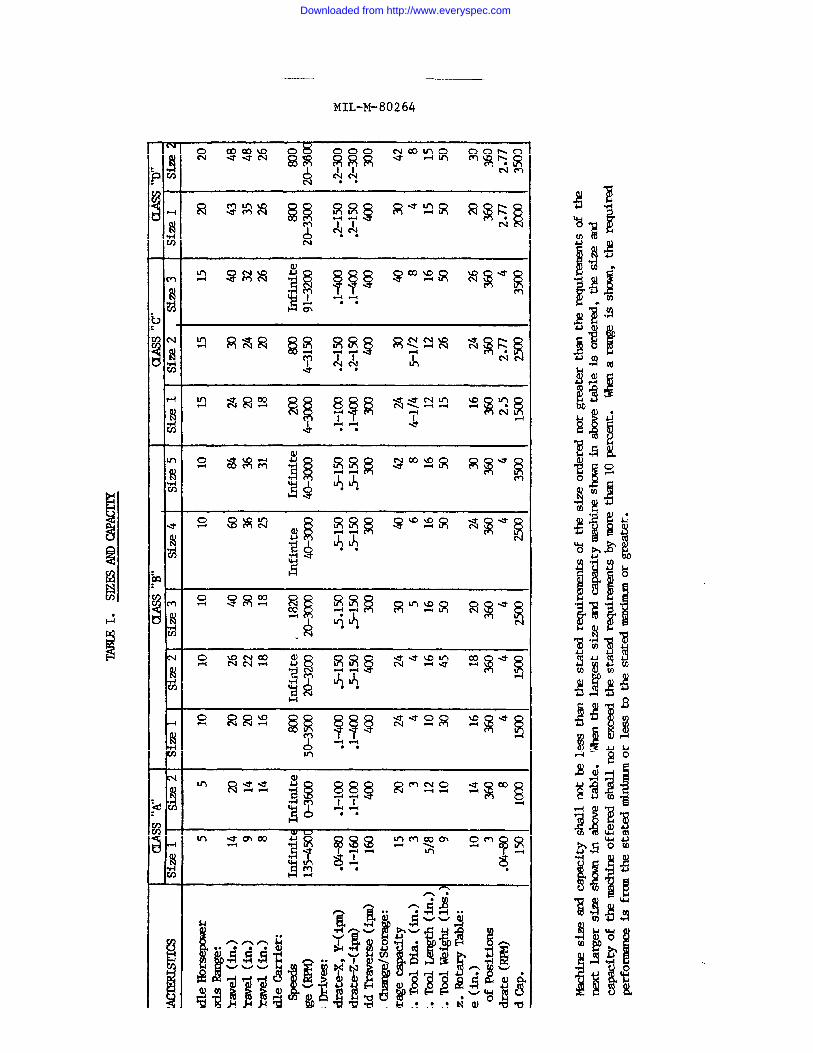
1.2 Classification. The horizontal spindle machining center covered bythis specification shall be of the following classes and sizes. Thespecific machining center class and size to be furnished shall be asspecified (see 6.2.1).
Beneficial comments (recommendations, additions, deletions) and anypertinent data which may be of use in improving this document should beaddressed to: Defense Industrial Plant Equipment Center, Memphis,Tennessee 38114, by using the self-addressed Standardization DocumentImprovement Proposal (DD Form 1426) appearing at the end of this docu-ment or by letter.
FSC 3408
Downloaded from http://www.everyspec.com
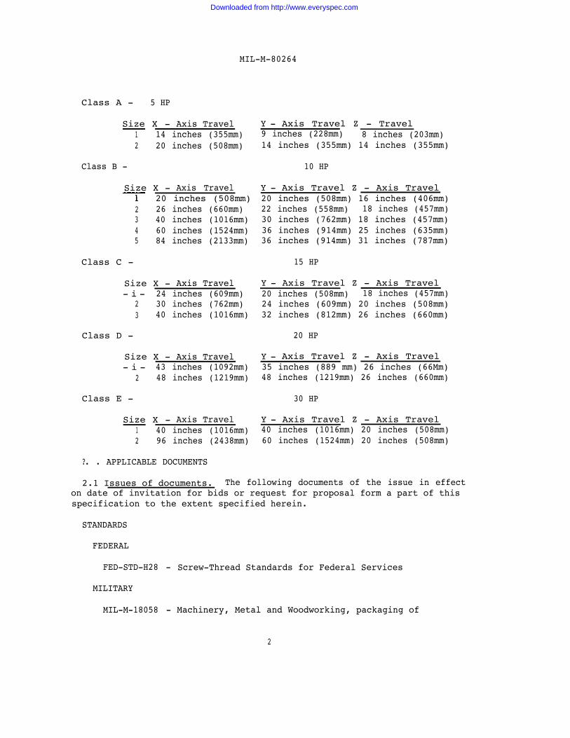
MIL-M-80264
Class A - 5 HP
Size X - Axis Travel1 14 inches (355mm)2 20 inches (508mm)
Class B -
Size X - Axis TravelT 20 inches (508mm)
2 26 inches (660mm)3 40 inches (1016mm)4 60 inches (1524mm)5 84 inches (2133mm)
Class C -
Size X - Axis Travel- i - 24 inches (609mm)
2 30 inches (762mm)3 40 inches (1016mm)
Class D -
Size X - Axis Travel- i - 43 inches (1092mm)
2 48 inches (1219mm)
Class E -
Size X - Axis Travel1 40 inches (1016mm)2 96 inches (2438mm)
Y - Axis Travel Z - Travel9 inches (228mm) 8 inches (203mm)14 inches (355mm) 14 inches (355mm)
10 HP
Y - Axis Travel Z - Axis Travel20 inches (508mm) 16 inches (406mm)22 inches (558mm) 18 inches (457mm)30 inches (762mm) 18 inches (457mm)36 inches (914mm) 25 inches (635mm)36 inches (914mm) 31 inches (787mm)
15 HP
Y - Axis Travel Z - Axis Travel20 inches (508mm) 18 inches (457mm)24 inches (609mm) 20 inches (508mm)32 inches (812mm) 26 inches (660mm)
20 HP
Y - Axis Travel Z - Axis Travel35 inches (889 mm) 26 inches (66Mm)48 inches (1219mm) 26 inches (660mm)
30 HP
Y - Axis Travel Z - Axis Travel40 inches (1016mm) 20 inches (508mm)60 inches (1524mm) 20 inches (508mm)
?. . APPLICABLE DOCUMENTS
2.1 Issues of documents. The following documents of the issue in effecton date of invitation for bids or request for proposal form a part of thisspecification to the extent specified herein.
STANDARDS
FEDERAL
FED-STD-H28 - Screw-Thread Standards for Federal Services
MILITARY
MIL-M-18058 - Machinery, Metal and Woodworking, packaging of
2
Downloaded from http://www.everyspec.com
MIL-M-80264
MIL-STD-461 - Electromagnetic Emission and SusceptibilityRequirements for the Control of ElectromagneticInterferences
(Copies of specifications, standards, drawings, and publications requiredby contractors in connection with specific procurement functions should beobtained from the procuring activity or as directed by the contractingofficer.
2.2 Other publications. The following documents form a part of thisspecification to the extent specified herein. Unless otherwise indicated,the issue in effect on the date of invitation for bids or request forproposal shall apply.
U. S. DEPARTMENT OF LABOR
OSHA 2206 - General Industry, OSHA Safety and Health Standards(29 CFR 1910)
(Application for copies should be addressed to the Superintendent ofDocuments, Government Printing Office, Washington, DC 20492.)
AMERICAN NATIONAL STANDARDS INSTITUTE (ANSI)
B5.1 - T-Slots, Their Bolts, Nuts and TonguesB5.50 - ‘V’ Flange Tool Shanks for Machining Centers with Automatic
Tool ChangersB11.8 - Construction, Care and Use of Drilling, Milling and Boring
Machines, Safety Requirements for theC113.1 - Electrical Standards for Metalworking Machine
Tools (NFPA NO. 79)Z210.1 - Metric Practice (ASTM-E380)
(Application for copies should be addressed to the American NationalStandards Institute, ATTN: Sales Dept.; 1430 Broadway, New York, NY10018).
NATIONAL FIRE PROTECTION ASSOCIATION (NFPA) STANDARDS
NFPA No. 79 - Electrical Standards for Metalworking Machine Tools
(Application for copies should be addressed to the National FireProtection Association, 470 Atlantic Avenue, Boston, MA 02110).
ELECTRONIC
RS-227 -
RS-232 -
lNDUSTRIES ASSOCIATION (EIA) STANDARDS
one Inch perforated Tape
Interface between Data Terminal Equipment and DataCommunication Equipment Employing Serial Binary DataInterchange
3
Downloaded from http://www.everyspec.com
RS-244 -
RS-267 -
RS-274 -
Rs-281 -
RS-358 -
RS-447 -
RS-494 -
MIL-M-80264
Character Code for Numerical Machine Tool ControlPerforated Tape
Axis and MotionMachine Tools
InterchangeableContouring, and
Nomenclature for Numerically Controlled
Variable Block Format for Positioning,Contouring/Positioning Numerically
Controlled Machines
Construction Standards - Numerical Machine Tool Control
Subset of American National Standard Code for InformationInterchange for Numerical Machine Control Perforated Tape
Operational Command and Data Format for NumericallyControlled Machines
32 Bit Binary CL Exchange (BCL) Input Format for NumericallyControlled Machines
(Application for copies should be addressed to Electronic IndustriesAssociation, Engineering Department, 2001 Eye Street, N.W., Washington, DC20006.)
NATIONAL ELECTRICAL MANUFACTURERS ASSOCIATION (NEMA) STANDARDS
MG-1 - Motors and Generators
(Application for copies should be addressed to the National ElectricalManufacturers Association, 155 East 44th Street, New York, NY 10017.)
NATIONAL STANDARDS ASSOCIATION
NAS-979-Uniform Cutting Tests - NAS Series Metal Cutting EquipmentSpecifications
(Application for copies should be addressed to the National StandardsAssociation, Inc., 1321 Fourteenth Street, N.W., Washington, D.C. 20005.)
(Technical society and technical association specifications and standardsare generally available for reference from libraries. They are alsodistributed among technical groups and using Federal agencies.)
3. REQUIREMENTS
3.1 First article. When specified (see 6.2.1), the contractor shallfurnish one complete machining center for first article inspection andapproval (see 4.2).
4
Downloaded from http://www.everyspec.com
MIL-M-80264
3.2 Design. The horizontal machining center shall bemanufacturer’s current models. Its design shall include
new and one offeatures and
the
components necessary for maintaining alignment and accomplishing drilling,tapping, milling and boring required herein. The machine shall be of afixed base type with vertical movements on the column ways. Cross movementmay be provided either by movement of the spindle assembly on a columnsupported saddle, or by movement of the table on saddle ways supported bythe bed. Tools, toolholders, and adapters shall be inserted and removedfrom the spindle by an automatic tool changer with storage magazine. Toolchanges, spindle operation, operation of 3 linear axes and one rotarypositioning axis, and other operations as specified herein, shall bedirected by a softwired numerical control system. The numerical controlsystem shall consist of a softwired numerical control unit, solid stateaxis drives, electric axis drive motors, solid state electric spindle driveand electric motor, axis feedback devices configured so as to provide aclosed loop system and all other hardware and software necessary fornumerical control operation of the machine. The machine and its numericalcontrol shall constitute a completely functional system. The machinefunctions shall be controlled manually by operator control devices,semi-automatically by manual data input devices, and automatically frompart program input data. All parts of the machine and system that aresubject to wear, breakage, or distortion shall be accessible foradjustment, replacement, and repair.
3.2.1 Measurement systems. Unless otherwise specified, either the U.S.Customary System of Units (US) or the International System of Units (SI)may be used in the design and construction of the machine. When only onesystem of measurements is acceptable, the particular system required shallbe as specified (see 6.2.1). In this specification all measurements,dimensions, sizes and capacities are given in the U.S. Customary System ofUnits (US). These measurements may be converted to the InternationalSystem of Units (SI) through the use of the conversion factors and methodsspecified in ANSI Z210.1.
3.2.1.1 Measuring and indicating device calibrations. When specified(see 6.2.1), measuring and indicating devices such as feed screw dials,scales, depth stops, carriage stops, dial indicators, pressure gauges,temperature indicators, and all other similar devices shall be graduatedthe specified system (US or SI) of measurement. Regardless of themeasurement system used, all measuring and indicating devices on themachine shall be graduated in the same system.
in
3.2.1.2 Dual calibrations. When specified (see 6.2.1), measuring andindicating devices shall be graduated in both the US and SI System ofMeasurements. When a dual US and SI system is furnished, both feed dialsshall have independent zero adjustments and both dials shall be calibratedin such a manner that the last dial graduation progresses into and iscontinuous with the first dial graduation as the dial is rotated throughthe zero position.
Downloaded from http://www.everyspec.com
MIL-M-80264
3.2.2 Reclaimed materials. The machining center shall contain reclaimedmaterials to the maximum extent possible without jeopardizing its intendeduse and performance. The reclaimed materials shall have been eitherreprocessed, remanufactured, or recycled in a manner which restores them tothe same chemical composition and physical properties as the materialsoriginally selected for use on the machine.
3.2.3 Operating controls. All operating controls necessary for manualand tape operation of the machine shall be mounted on either a controlconsole or pendant stand clearly identified to facilitate its use. Voltageand current meters, indicator lights, and all other operational controlaids shall be arranged and mounted convenient to and in full view of theoperator. An emergency stop switch shall be furnished on the controlstation,
3.2.4 Safety and health requirements. Covers, guards, and other safetydevices shall be provided for all parts of the machining center thatpresent safety hazards. The safety devices shall not interfere withoperation of the machine. The safety devices shall prevent unintentionalcontact with the guarded part, and shall be removable to facilitateinspection, maintenance and repair of the parts. All machine parts,components, mechanisms, and assemblies furnished on the machine, whether ornot specifically required herein, shall comply with all of the requirementsof "OSHA Safety and Health Standards (29 CFR 1910), General Industry” thatare applicable to the machine itself. In addition, the machine shallcomply with all requirements of ANSI B11.8 that are designated therein asthe responsibility of the machine manufacturer. In the event of conflictbetween the requirements of OSHA and the ANSI Standards, the requirementsof OSHA shall apply. Additional safety and health requirements shall be asspecified (see 6.2.1).
3.3 Construction. The machining center shall be constructed of partswhich are new, without defects, and free of repairs. The structure shallbe capable of withstanding all forces encountered during operation of themachine to its maximum rating and capacity without permanent distortion.
3.3.1 Castings and forgings. All castings and forgings shall be free ofscale and mismatching. No process such as welding, peening, plugging, orfilling with solder or paste shall be used for reclaiming any defectivepart.
3.3.2 Welding, brazing, or soldering. Welding, brazing, or solderingshall be employed only where specified in the original design. None ofthese operations shall be employed as a repair measure for any defectivepart.
3.3.3 Fastening devices. All screws, pins, bolts, and other fastenersshall be installed in a manner that prevents change of tightness. Thosesubject to either removal or adjustment shall not be swaged, peened, stakedor otherwise permanently installed.
6
Downloaded from http://www.everyspec.com
MIL-M-80264
3.3.4 Surfaces. All surfaces shall be cleaned and free of sand, dirt,fins, sprues, flash, scale, flux, and other harmful or extraneousmaterials. All edges shall be either rounded or beveled unless sharpnessis required to perform a necessary function. Except as otherwise specifiedherein, the condition and finish of all surfaces shall be in accordancewith the manufacturer’s commercial practice.
3.3.5 Painting. Unless otherwise specified (see 6.2.1), the machiningcenter shall be painted in accordance with the manufacturer’s commercialpractice.
3.3.6 Threads. Unless otherwise specified (see 6.2.1), all threadedparts used on the machine and its related attachments and accessories shallconform to FED-STD-H28 and the applicable “Detailed Standard” sectionreferenced therein.
3.3.7 Dials. Unless otherwise specified (see 6.2.1), dials shall begraduated in either the inch or metric (SI unit) system. Graduations toindicate stock removal or tool movement shall be in increments of not morethan 0.001 inch or the equivalent on the metric scale. The size of dialfaces shall be such that the graduations are easily read. Dial faces shallbe permanently and legibly engraved, stamped, or etched and shall have anon-glare finish.
3.3.8 Plates. All words on instruction and indicating plates shall bein the English language. Characters shall be either engraved, etched,embossed, or stamped in boldface on a contrasting background.
3.3.9 Gears. All gears shall he machined from a material suitable forthe intended purpose. All gears shall be heat treated by a process thatwill impart the hardness and toughness that will enable the gear train totransmit full rated torque of the drive motor without gear damage, failure,or premature wear.
3.4 Components. The machine shall consist basically of the followingcomponents. Any additional components necessary to the operation of themachine shall be furnished in accordance with manufacturer’s standardpractice.
3.4.1 Base. The base shall possess the mass, strength, rigidity andother load carrying characteristics necessary for supporting the column,saddle and associated components. The base shall form a foundation for thecomponents supported and shall be sufficiently rigid for maintaining mutualcomponent alignment necessary to maintain the accuracies specified herein.The base shall have bedways that are proportioned to support andaccommodate the precision movements of the supported components through thefull range of travel. The base shall have either access doors or removableplates for cervicing internal components. Fluid reservoirs shall be eitherhoused within the base or supplied as separate external units. The base
Downloaded from http://www.everyspec.com
MIL-M-80264
shall have means for leveling and securing the machine to a mountingsurface or foundation.
3.4.2 Column. The machine shall be structured with a stationary typecolumn. Slide movement shall be independently driven by solid state servodrives, electric motor and precision ballscrew with recirculating ball nut.Column slides and screws shall be shielded and protected from foreigncontamination by either telescoping or curtain type covers and way wipers.Either a brake or a counter balance shall be provided to automaticallyprevent machining head movement in the event of power loss. Either stopsor limit switches at the upper and lower extremes of the column ways shallprevent excessive travel of the machining head. The column shall bearranged to support and accommodate the machining head and spindle drivemechanism. The column shall be of a box-like construction with adequatestrength and proportions to sustain, without distortion, all dynamic forcesimposed by full load machining operations. The column shall have thedegree of static rigidity necessary for maintaining chatter-free andoscillation-free operation at all spindle speed and axes feed rates.
3.4.3 Z axis. In and out movement (Z axis) shall be accomplished byeither a sliding table, machining head, or quill. The Z axis shall beindependently driven by solid state servo drive, electric motor andprecision ballscrew with recirculating ball nut. The Z axis slide shall besecured in place, over the entire travel range, by either servo devices orcomparable means as directed by the numerical control unit. The Z axisslides and screws shall be shielded and protected from foreign elements byeither telescoping covers or curtain type covers and way wipers.
3.4.4 Spindle assembly. The spindle shall be fixed and held in axialand radial alignment by ball or roller bearings. The spindle shall bemounted in the machining head with its bearings designed and arranged tocompensate for thermal expansion. The spindle shall have positive meansfor accepting, retaining and releasing tools and tool holders inserted bythe automatic tool changer and operator. Unless otherwise specified (see6.2.1), the spindle nose taper shall accept Sizes 24 or 50 “V” flange toolshanks complying with ANSI B5.50. The tool holder shall be held in thespindle by means of a retention knob and automatic drawbar. The spindleshall be driven by a variable speed electric motor. The spindle shall becapable of both clockwise and counterclockwise directions of rotation foraccomplishing the full range of spindle speeds specified herein. Thespindle shall automatically stop rotation for tool changes. Overloadprotection shall automatically stop spindle rotation and the motions of allslides upon an overload, and spindle stall. All spindle bearings, gears,shafts, and clutches shall be constantly flooded by temperature controlledlubricating oil to stabilize the machine and control spindle growth due tomachine operation or changes in ambient temperature when required to attainand ensure the dimensional accuracy stated within this specification.
3.4.5 Saddle. The saddle shall be supported on horizontal ways. Thesaddle slide shall be independently driven by solid state servo drive and
Downloaded from http://www.everyspec.com
MIL-M-80264
electric motor through a precision ball screw with recirculating ball nut.The saddle slide shall be secured in place, over the entire saddle travelrange by either servo devices or comparable means as directed by thenumerical control unit. Saddle slides and screws shall be shielded andprotected from coolant, chips, and other contaminants by either telescopingcovers or curtain type covers and way wipers.
3.4.6 Tool changer and storage magazine. The machine shall be equippedwith an automatic tool changer and storage magazine with, unless otherwisespecified (see 6.2.1), a storage capacity as specified in Table I. Toolchange shall be accomplished automatically by a power activated arm whichwill interchange the tool in the spindle with a tool selected from the toolstorage magazine. The magazine shall permit convenient loading andunloading of tool holders during operational setup. Random access toolselect ion capability shall be provided. The machine shall have thecapability of reusing a tool that has been returned to the storage magazineafter a programmed operation. The storage magazine shall be of the closedloop recirculating configuration.
3.4.7 Worktable. Unless otherwise specified (see 6.2.1), the number,size and configuration of T-slots in the tables shall be the manufacturers
standard. The top of the worktable shall be machine finished for a workmounting surface. The table shall have coolant troughs or similar meansfor draining spent coolant into its reservoir. Edge block locators shallbe provided on two adjacent sides of the table. The rotary table shall becapable of the number of positions as specified in Table I controlled bythe numerical control unit. The table shall be independently driven bysolid state drive and electric motor. The rotary table shall be driven byan anti-backlash gearbox with independent type scales mounted for feedback.The table and all slides shall be provided with an automatic positive meansof securing machine components in place to permit accurate cuts under fullhorsepower, without drifting.
3.4.8 Lubrication. A lubrication system shall be provided which willensure adequate lubrication for all moving parts. The system shall beautomatic with positive metering capability and shall deliver lubricatingoil to all ball screws, mating gears, sliding parts, and bearings exceptsealed-for-life-type. Each lubricant reservoir shall have a means fordetermining and maintaining fluid level. The lubricant reservoir shallhave sufficient capability to operate for a minimum of 80 hours of feedtime without being serviced. The lubrication system shall have a devicefor indicating oil level and a low level pressure warning and protectionsystem to alert the operator and stop spindle and axis motion.Recirculated oil shall be filtered by a cleanable or replaceable typefilter. Mechanisms requiring periodic manual lubrication shall be readilyaccessible for servicing. A recommended preventive maintenance schedule,both electrical and mechanical, shall be provided.
9
Downloaded from http://www.everyspec.com
MIL-M-80264
3.4.9 Coolant system. The machine shall be supplied with a completeflood and mist type coolant system with numerically controlled “selection ofcoolant type and on/off of coolant flow. The system shall have adequatecapacity for all types of machining operations for which the machine isdesigned and shall have means for regulating the flow of flood coolant andfor adjusting mist coolant supply as required. All components necessary tomake the system completely functional shall be furnished includingreservoirs, chip screens, filters, drain troughs, and clean-out plates.
3.4.10 Hydraulic system. The hydraulic system, when supplied, shall becomplete with pumps, valves, piping, cylinders, reservoir, and pressurecontrols. Overpressure protection shall be provided on the high pressureline from the hydraulic pump to prevent damage to components. The systemshall include filters to insure delivery of clean fluid. The reservoirshall have a sight gage to indicate the fluid level. The fluid temperatureshall be maintained within the proper operating range during all normaloperations of the machine. When required, noise level and noisesuppression enclosures for stand-alone hydraulic units shall be asspecified (see 6.2.1).
3.4.11 Electrical system. Unless otherwise specified (see 6.2.1), theelectrical system shall conform to ANSI/NFPA 79. Unless otherwisespecified (see 6.2.1), the machine shall operable on both 230 volts and 460volts , 3 phase, 60 Hz source and shall be initially wired for operation on460 volts. An identified terminal shall be provided, suitable forconnection of a grounding conductor. It shall be possible to operate allelectrical equipment on the machine after connection to a single powersource. When specified (see 6.2.1), electric noise suppression devicesshall be used where applicable.
3.4.11.1 Motors. All motors shall be equipped with ball or rollerbearings and have a short time rating of 60 minutes. Motors shall beeither AC, 3 phase, 60 Hz or industrial DC motors conforming to NEMAStandard MG1-10-61, paragraph B, equipped with a solid state rectifier.Variable speed DC spindle motors shall develop rated horsepower through atleast 90 percent of the range of spindle speeds available from a gear trainor direct coupling. Each electric motor shall be a totally enclosed or ina dripproof blower cooled enclosure.
3.4.11.2 Main electrical disconnect. A manually operated fusibledisconnect switch or circuit breaker of adequate size to carry the entireelectrical load of the equipment shall be provided for connection to theprimary power source specified.
3.4.12 Machine ways. The machine ways shall be adequately protectedwherever possible to exclude chips, dirt, coolant, and other hazards thatmay cause damage or result in inaccurate functioning of any members. Themachine ways shall be hardened and ground and suitable for the high gradeprecision numerically controlled machines covered by this specification.
Downloaded from http://www.everyspec.com
MIL-M-80264
Linear slide movement over the ways shall be supported by either rollerpacks or non-metallic liners.
3.4.13 Chip conveyor system. Unless otherwise specified (see 6.2.1), achip conveyor system shall be provided to automatically remove chips fromthe work
3.4.14pressuredrillingstandard
3.4.15
area and dumped into a container.
Coolant through the spindle. When specified (see 6.2.1), lowcoolant through the spindle shall be provided for deep holeor operations where the cutting tool can not be reached with thecoolant system.
Pallet shuttle system. When specified (see 6.2.1), the machineshall have a pallet shuttle system arranged for the mechanized removal andprecise reattachment of worktable tops. Unless otherwise specified (see6.2.1), the system shall be comprised of a minimum of two duplicate palletsand a workchange mechanism which is functional for automatically transferr-ing a pallet from the machine’s work zone area to a workpiece load areawhile either simultaneously or consecutively transferring and attaching theother pallet in the reverse process. The pallet system shuttle shall beoperated by the numerical control for accomplishing automatic pallet changefor the execution of both individual and alternate part programs withoutoperator intervention except to start the cycle between programs. Thecomplete automatic programmable pallet change shall be accomplished within45 seconds. Control shall be included for automatic pallet change,inhibit, and manual cycle. Automatic pallet changes shall be preceeded byan audio type warning signal for a period of not less than five seconds. Apallet change inhibit switch shall be provided in a location readilyaccessible by an operator who is at the off-line pallet.
3.4.16 Numerical control. The machining center shall have a fullyautomatic solid state soft-wired, integrated circuit type numericalcontrol. The machine control unit (MCU) shall provide automatic control ofmachine functions, operating modes, three linear axes feedrate control,positioning control of the rotary table, spindle speed and direction ofspindle rotation, and other part program directed functions for machiningcenters of the type specified herein. Controlled axes be identified inaccordance with EIA Standard RS-267. The control shall have linear andcircular interpolation and be capable of simultaneous control of threelinear axis and positioning control of the rotary table and automaticoperation of the pallet shuttle. Control features shall include aprogrammable interface, buffer storage, fixed cycles, part program storage,part program and buffer edit capability, and control diagnostics. The MCUshall direct machine functions from part program data stored in memory,manually input or directly from the input media specified herein. Thecontrol shall initiate a halt or an error signal should a fault conditionoccur in the control. All necessary executive program routines shall befurnished in the form of one inch eight channel binary coded decimalpunched tape or 8 inch flexible disk for controls having volatile memory.The control unit shall conform to EIA Standard RS-281. A line voltage of
11
Downloaded from http://www.everyspec.com
MIL-M-80264
+1O% from normal shall not adversely affect the numerical control function.The control shall be capable of functioning in ambient temperatures rangingfrom 50 to 120 degrees F and humidity ranging from 5 percent to 95 percentnon-condensing. The control shall automatically shut down when internaloperating temperature exceeds safe operating temperature. Controlresolution shall be 0.0001 inch or 0.001 mm for each linear axis and notmore than 0.001 of a degree for each rotary axis. When binary cutterlocation (BCL) data is specified (see 6.2.1) the numerical control shallhave the necessary hardware and software to perform all geometry dependentfunctions which are ordinarily performed by the postprocessor.
3.4.16.1. MCU. The MCU shall provide full contouring control of themachines three linear axes and positioning control of the rotary tablefor performing drilling, tapping, boring, reaming, and contour millingoperations by simultaneous movement of each axis.
3.4.16.2 Data input.
3.4.16.2.1 Punched tape data input. Unless otherwise specified (see6.2.1) the input media for the control shall be one inch, light channelpunched tape. The data input format and codes shall comply with EIAStandards RS-274, RS-358 and RS-447 or when specified (see 6.2.1) RS-244shall apply in lieu of RS-358. The control shall be equipped with aphotoelectric tape reader capable of holding, feeding and reading tapeprepared in the format specified at a rate not less than 150 characters persecond. Unless otherwise specified (see 6.2.1), the tape reader shall besupplied with standard feed and take-up spoolers 5-1/4 inch in diameter.The tape reader shall be housed in a dust free area of the numericalcontrol cabinet and shall be easily accessible for cleaning and tapehandling. The control shall have a tape error detection capability tocontinuously check for the following errors:
a. Odd parity per EIA RS-244b. Even parity per EIA RS-358c. Misaligned sprocket holesd. No sprocket holes
Any of the above errors shall halt machine functions and illuminate anerror light or a message on the data display screen to indicate a faultcondition.
3.4.16.2.2 Flexible diskette data input. When 32 Bit Binary Cutter— . .Location (BCL) Exchange Input for Numerically Controlled Machines isspecified (see 6.2.1), the input media shall be an eight inch flexiblediskette recorded in accordance with 3.4.16.2.2.1. The input data formatshall comply with EIA Standard RS-494. Functions 10.1, 10.2 and 10.3 ofSection 10, EIA-RS-494 shall apply. Manufacturer’s providing functions orfeatures that can not be addressed by command codes currently covered byEIA-RS-494 shall apply to the Electronic Industries Association, IE-31Committee on Numerical Control Systems and Equipment for an extension of
12
Downloaded from http://www.everyspec.com
MIL-M-80264
the standard codes to cover theshall be equipped with an eight
new features or functions. The controlinch flexible diskette reader. The reader
shall have the capability to perform a cyclic redundancy check of the inputdata and be capable of reading not less than 15,000 characters per second.
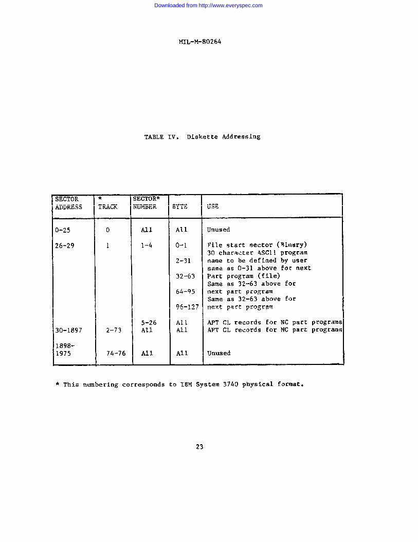
3.4.16 .2.2.1 Flexible diskette format. When an eight inch flexible diskis specified as the input media to the numerical control it shall be asingle density recording on one side using a soft sectored format. Thedisk shall be divided into 77 distinct locations on the single side disk.Tracks shall be assigned numbers from and trade 76 nearest the center.Tracks 00, 74, 75 and 76 shall not be used. There is an index hole in thejacket and the disk that shall be used for timing functiom when a beam Oflight passes through it. Recording shall be accomplished by rotating tiedisk inside its jacket exposing the disk at the read/writehead slot cut intie jacket. Data shall be recorded only on the side of the disk that isexposed to the read/write head. Each track shall be divided into 26addressable sectors which contain 128 bits. All sectors shall beidentified by the file startirq sector nurber with track 00, sector 1,designated as 0. The first part program shall be located at sector lEhexidecimal corresponding to track 1, sector 5. Where two byte numbers arereferenced the high order byte shall be recorded first and the low orderlast. The data stored in a sector is called a record. Track 1, sectors 1through 4 shall contain the program directory of up to 16 part programnames in ASCII. Each file shall be packed on tie disk in the same order asits directory entry. Unused directory entries shall point to the nextavailable sector after the last file and contain the 30 character ASCIIspace characters. The last sector of each file shall be padded with end offile (EOF) records (8000 0000). Diskette addressing shall comply with therequirements of table IV.
3.4.16.2.3 Manual data input. A manual data input (MDI) unit shall befurnished to permit manual entry of alphabetical, numerical, and specialcharacters necessary for control of all programmable machine functions.The manually input data shall be immediately displayed on the data displayto permit data verification. The MDI shall be capable of entering a blockof data into memory upon command
3.4.16.3 Data display. A cathode ray tube (CRT) capble of displayingat least 250 characters simultaneously. shall be provided. Unlessotherwise specified (see 6.2.1), the display shall, as a minimum, displaythe following data:
a. Four digit block sequence numberb. Active block of stored! data.
Actual position of each axis.“:: Feedrate and override condition.e. Control and system error messages.
13
Downloaded from http://www.everyspec.com
MIL-M-80264
3.4.16.4 Control system modes of operation. The operational modes ofthe NC control shall include manual, automatic, single block, MDI, sequence number search, and optional stop.
3.4.16.5 Departure control. The maximum departure permitted by a singlecommand in either incremental or absolute mode shall be not less than plusor minus 99.9999 inches or 999.999mm. The control shall be capable ofautomatically controlling the acceleration and deceleration of the slides.The resolution of slide movement in either direction shall not be more than0.0001 inch or 0.001mm.
3.4.16.6 Absolute/incremental input. The control shall have absolute/incremental input capability. This mode shall be selected by a preparatory“G” code which may be switched during the tape program. Not required ifBCL input is specified (see 6.2.1).
3.4.16.7 Automatic tape code recognition. The control shall have thecapability to automatically recognize and read tape punched with either EIARS-244 or RS-358 (ASCII) character codes. Not required if CL data input isspecified (see 6.2.1).
3.4.16.8 Switchable inch/metric input. The control system shall provideswitchable inch/metric input capability.
3.4.16.9 Part program storage. Unless otherwise specified (see 6.2.1)part program storage shall be in either solid state or bubble typememory. The MCU shall be capable of storing in memory the content of,unless otherwise specified (see 6.2.l), not less than 250 feet ofpostprocessed part-program tape data. - Not applicable if BCL data input isspecified (see 6.2.1).
3.4.16.10 Standby battery powe r. Unless otherwise specified (see6.2.1), standby battery power shall be provided for controls havingvolatile memory, to hold the memory provided at full load for a period ofnot less than 70 hours when the primary power source fails.
3.4.16.11 Part program edit. A program edit capability shall beprovided to allow block insertion, deletion or modification of any partprogram in the part program memory. Data related to part program editshall be input by the manual data input provided on the control panel.Edited program data entered into program memory shall be automaticallyacted upon,cycled.
3.4.16.12provided toto not less
in the sequence designated, whenever the part program is
Feed rate override. A feed rate override control shall beallow manual adjustment of the programmed feed rate from zerothan 120 percent of the programmed rate in either continuous
adjustment or in steps of not more than 10 percent. The feed rate over-ride control shall have a position that allows return of feed rate to thatprogrammed.
14
Downloaded from http://www.everyspec.com
MIL-M-80264
3.4.16.13 Spindle speed override. A spindle speed override shall beprovided to allow manual adjustment of spindle speed in either continuousadjustment or in steps of not greater than 10 percent each. The spindlespeed override control shall control not less than the range of overridepercentages between 60% and 120% of programmed speed. The spindle speedoverride control shall have a position that allows return of speed to thatprogrammed.
3.4.16.14 Sequence number search. The control shall have the capabilityto permit the operator to search for any desired sequence number.
3.4.16.15 Mirror image. The machine shall be capable of producingeither right or left-hand from the same tape data through the inversion ofx and y axis. Inversion of each axis shall be by keyboard or switch entry.Mirror image shall not affect the directional sense of manual controls.Reverse settings shall be displayed on the data display.
3.4.16.16codes of thethe BCL data
3.4.16.17codes of thethe BCL data
3.4.16.18
preparatory function (G-Codes). The preparatory functioncontrol shall be in accordance with EIA Standard RS-274. Ifinput is specified, codes in EIA-RS-494 shall be applied.
Miscellaneous functions (M-Codes). me miscellaneous functioncontrol shall be in accordance with EIA Standard RS-274. Ifinput is specified, codes in EIA-RS-494 shall be applied.
Block delete. The control shall have a block delete featureto permit by-passing of blocks of programmed data.
3.4.16.19 Buffer storage. The control shall have buffer storage fortransferring command data from the tape reader to internal storage withoutdelaying the next incoming command and without interrupting the machinefunctions. The internal storage shall delay or store multiple blocks ofdata until required by the controlling devices.
3.4.16.20 Block-by-block read. The control shall have a block-by-blockread function to provide for reading information one block at a time.
3.4.16.21 Tool length offsets. The control shall have a tool lengthoffset feature to permit adjustments to the programmed tool length by meansof manual data input. The tool length offset feature shall have a range ofnot less than the following:
a. Inch system ~O.0002° to~l.0000”b. Metric system fi.002mm to~25.40@nm.
3.4.16.22 Cutter compensation. Cutter compensation shall be provided tocompensate for cutter diameters differing from those utilized inprograming. The cutter compensation shall have a range of not less thanthe following:
15
Downloaded from http://www.everyspec.com
MIL-M-80264
a. Inch system -j-O.0002° to +1.0000”b. Metric system fi.002mm to ~25.400mm.
3.4.16.23 Fixture compensation. A fixture compensation feature shall be provided to permit compensation for fixture position errors.
3.4.16.24 Reversal error compensation. Reversal error compensationshall be provided for each axis of motion to compensate for drive gearbacklash when slide reversal occurs. A means shall be provided to inputnew compensation values when required.
3.4.16.25 Axis calibration. Error compensation shall be provided tocorrect repeatable errors determined to exist due to leadscrew and feedbackdevice inaccuracies. A means shall be provided to input new errorcompensation values when required.
3.4.16.26 Additional features. Unless otherwisethe following additional numerical control features
a. Four quandrant programming
specified (see 6.2.1),shall be provided:
b. Incremental and continuous jog for each axisc. Leading zero suppression or decimal point programmingd. Inches per minute (IPM)/Millimeters Per Minute (MMPM),
programming in all modes of operatione. Tape edit keylock.
3.4.16.27 Operator control panel. Unless otherwise specified (see6.2.1), the control unit shall have a control panel which provides at least the following control functions: Emergency Stop; Cycle Start; OptionalStop; Mode Selection; Feed Hold; Feedrate Override; Spindle Speed Override;Jog; Jog Direction; and EOB Stop.
3.4.16.27.1 pendant control. When specified (see 6.2.1) a pendantcontrol shall be furnished in lieu of an operator control panel. Thependant control shall be connected to the machine to enable the operator tocontrol machine functions while in a close observation position. Unlessotherwise specified (see 6.2.1), the pendant control shall be capable ofthe same functions as stated for the operator control panel in paragraph3.4.16.27.
3.4.16.28 Reference zero. The control unit shall have a reference zeroto move each axis to a reference limit switch to establish synchronizationand reset all registers to zero.
3.4.16.29 Set zero. The control unit shall have a “set zero’* feature topermit the specified axis register to be reset to zero establishing presentaxis location as zero. .
16
Downloaded from http://www.everyspec.com
MIL-M-80264
3.4.16.30 Program tryout. The control shall have a program tape tryoutfeature to permit new part programs to be read through the control withoutmachine motions.
3.4.16.31 Operational software. Operational software shall be residentin the control and shall contain all logic necessary to effectively operatethe machine tool. The software shall provide for meaningful diagnosticsrelating to the utilization of the controls, machine tool, part program,and operator’s actions.
3.4.16.31.1 Programmable interface. A software program foraccommodating the softwired interface between the numerical control andmachine shall be provided as part of the executive program or as a separateprogram in the form of one inch, eight channel punched tape complying withEIA-RS-244 or eight inch flexible diskette as appropriate for the inputmedia specified (see 6.2.1).
3.4.16.32 Maintenance diagnostics system. Maintenance diagnosticssoftware shall be furnished in either the control as non-volatile memory orin the form of one inch, eight channel punched tape complying withEIA-RS-244 or eight in flexible disk as appropriate for the input mediaspecified(see 6.2.1) to provide for diagnostic checking of the machinecontrol unit. The diagnostic software shall test, exercise, and displayfailures, at least to board level.
3.4.16.33 Peripheral equipment interface. The control shall be equippedwith an interface complying with RS-232.
3.4.16.34 Axis jog. The control panel or pendant shall have manualcontrols for accomplishing both single and continuous, low and high speedjog movements of the slides for each controlled axis in both the plus andminus direction.
3.4.16.35 Auxiliary functions. Unless otherwise specified (see 6.2.1),the MCU shall respond to the following program commanded auxiliaryfunctions: interpolation, fixed cycles, and dwell. Unless otherwisespecified (see 6.2.1), miscellaneous functions shall include program stop,optional program stop, end of program, spindle CW, spindle CCW, spindleoff , coolant on-off, tool change, end of program (rewind), and programre-start. System preparatory and miscellaneous functions shall be coded inaccordance with EIA RS-274.
3.4.16.36 Canned cycles. The following canned cycles shall beprovided:
DrillingBoringTapping
Downloaded from http://www.everyspec.com
MIL-M-80264
3.4.16.36.1 Macro program cycles. The following flexible macro program—..—. -cycles shall be provided:
a. Milling c. Boringb. Drilling d. Tapping
3.4.16.37 Tape punch unit. When specified (see 6.2.1), the system shallhave a tape punch unit for producing punched tapes from edited programs ofstored in data memory. The unit shall have a plug receptacle and circuitrythat is compatible with the tape punch output of the system, punching bothpaper and mylar tapes of dimensions characteristics and code in accordancewith 3.4.16.2. The punching speed of the unit shall be not less than 75characters per second.
3.4.16.38 Postprocessor. When specified (see 6.2.1), the system shallbe furnished with a postprocessor program(s) to be utilized in off-linecomputer assisted preparation of part programs. The postprocessor shall beprovided for converting specified programming language (see 6.2.1) to theform and format required to operate the machine tool and control. Thepostprocessor shall be written for use on the type computer specified (see6.2.1). Documentation sufficient to implement and utilize the postproces-sor shall be provided for computer compatibility verification and valida-tion at least 30 days prior to delivery of the machining center.
3.4.16.39 Graphics software. When specified (see 6.2.1), graphicssoftware shall be provided which will allow communication between thespecified (see 6.2.1) user graphics system and the machine control unit.
3.4.17 Standard equipment. Unless otherwise specified (see 6.2.1), thefollowing equipment shall be furnished with the machine:
a. A load meter installed on the machine or MCU console thatconstantly registers the horsepower load (horsepower units orpercent of load) on the spindle rotation drive motor..
b. One set of special wrenches, operating, and repair tools that arenormally furnished by the manufacturer.
3.4.18 Optional equipment. The following optional equipment shall befurnished as specified (see 6.2.1):
a. A worklight, conveniently mounted to illuminate the work area,complete with protective shield and on-off switch.
b. An elapsed time indicator of the non-reset type, with digitalreadout and designed to resist the effects of vibration, voltagefluctuation, temperature change, and humidity. The indicatorshall be mounted on the machine in a position visible from theoperator’s station and be connected to record and accumulatemachine operating time to not less than 9999.9 hours.
18
Downloaded from http://www.everyspec.com
MIL-M-80264
c. Tools, took holders, and adapters, as specified.
d. Other optional equipment as specified.
3.5 Sizes and capacities. Unless otherwise specified (see 6.2.1). thesizes and capacities of the machining center shall meet the requirements ofTable I as applicable for the machine size specified in the contract ororder.
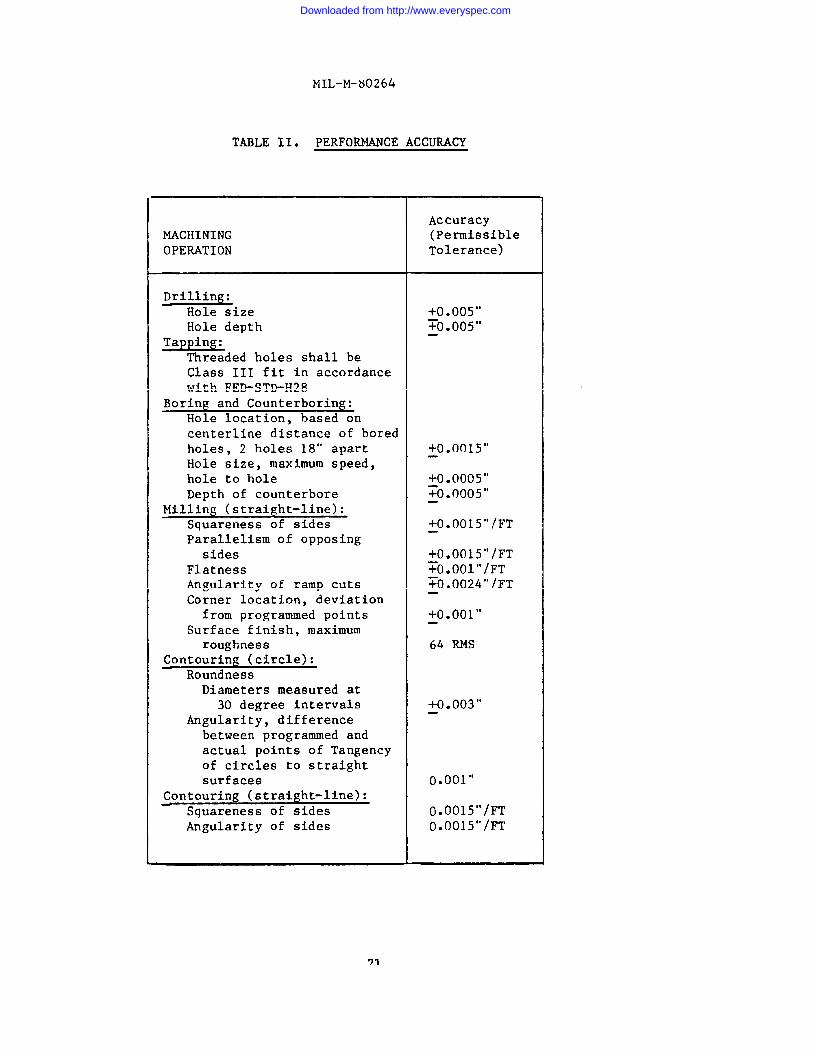
3.6 Performance. The machine and numerical control system combinationshall be capable of performing as specified herein. In addition, themachine shall be capable for performing drilling, tapping, milling andboring to accomplish the capacities of Table I while meeting the accuraciesof Table II.
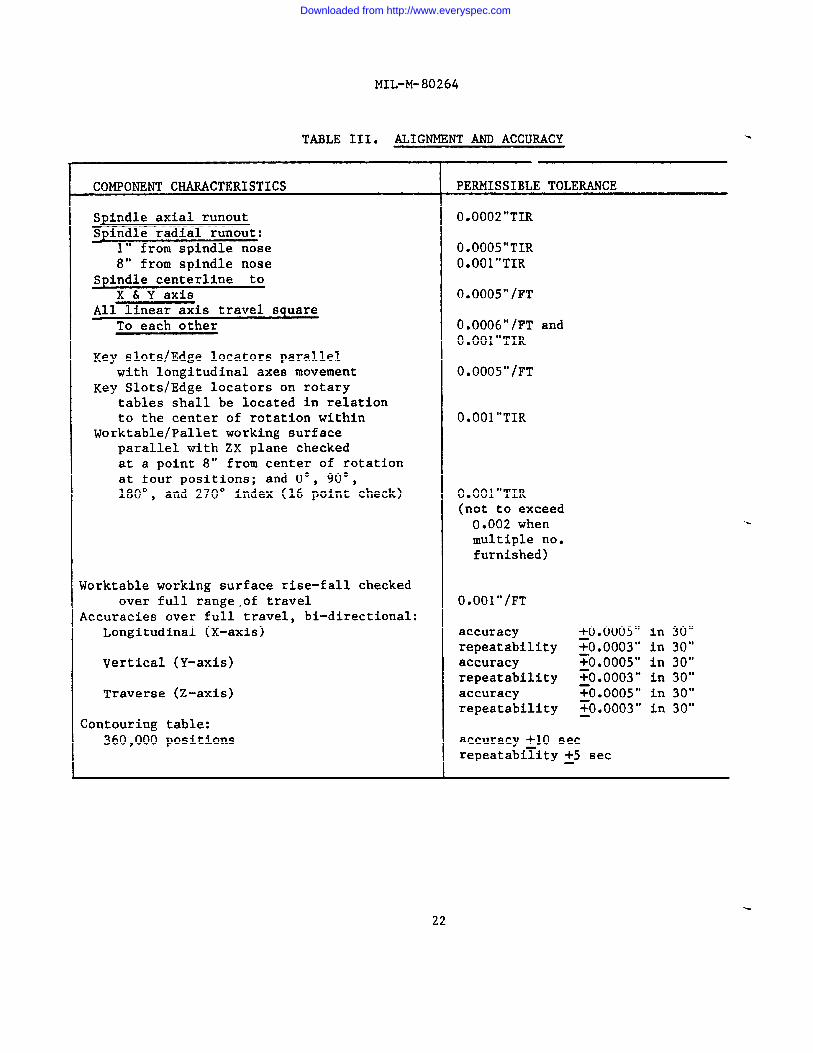
3.7 Alignment. The machine shall meet the alignment and accuracytolerances of Table III.
3.8 Electromagnetic interference control. When specified (see 6.2.1),equipment procured under this specification shall comply with therequirements of MIL-STD-461.
19
Downloaded from http://www.everyspec.com
Downloaded from http://www.everyspec.com
Downloaded from http://www.everyspec.com
Downloaded from http://www.everyspec.com
Downloaded from http://www.everyspec.com
MIL-M-80264
3.9 Lubrication chart or plate. Unless otherwise specified (see 6.2.1),a lubrication chart or plate shall be permanently and securely attached tothe machine. If a chart is furnished, it shall be placed in a transparentplastic folder or permanently sealed between clear plastic sheets withsuitable means for mounting. The following information shall be furnishedon the chart or plate.
Points of applicationService intervalType of lubricantviscosity
3.1O Nameplate. Unless otherwise specified (see 6.2.1), a corrosionresistant metal nameplate shall be securely attached to the machine. Thenameplate shall contain the information listed below. If the machine is aspecial model, the model designation shall include the model of the basicstandard machine and a suffix identified in the manufacturer’s permanentrecords. The captions listed may be shortened or abbreviated, provided theentry for each such caption is clear as to its identity.
NomenclatureManufacturer's nameManufacturer's serial numberManufacturer's model designationNumber of rotary table positions , Number of axes
contouringClass, , HP spindle motorSize, , axis travel (inches) X Y ZTool changer cap., t o o l s — —
Power input (volts, total amps, phases, frequency)Contract Number or Order NumberNational Stock Number, or Plant Equipment CodeDate of manufactureu s
3.11 Technical data. Data shall be furnished as specified (see 6.2.1).
3.12 Workmanship. Workmanship of the machine and accessories shall beequal to that of the manufacturers current commercial machines of the typespecified herein.
4. QUALITY ASSURANCE PROVISIONS
4.1 Responsibility for inspection. Unless otherwise specified in thecontract or purchase order, the supplier is responsible for the performanceof all inspection requirements as specified herein. Except as otherwisespecified in the contract or order, the supplier may use his own or anyother facilities, suitable for the performance of the inspection require-ments specified herein unless disapproved by the Government. TheGovernment reserves the right to perform any of the inspections set forth
24
Downloaded from http://www.everyspec.com
in the specification when such
MIL-M-80264
action is deemed necessary to assuresupplies and services conform to prescribed requirements.
4.2 Classification of inspections. The inspection requirementsspecified herein are classified as follows:
a. First article inspection (see 4.2.1)b. Quality conformance inspection (see 4.2.2).
4.2.1 First article inspection. When first article approval is requiredunder 3.1, first article inspection shall be performed. Unless otherwisespecified (see 6.2.1), the first article inspection shall comprise theexamination in 4.3 and all tests in 4.4. Failure of the item to pass anyexamination or test shall be cause for disapproval of the first article.
4.2.2 Quality conformance inspection. Each item shall be subjected toquality conformance inspection prior to being offered for acceptance.Unless otherwise specified (see 6.2.1) , quality conformance inspectionshall consist of the examination in 4.3, the test in 4.4 and the inspectionin 4.5. Failure of the item to pass either any examination, test orinspection shall be cause for rejection.
4.3 Examination. The machine and equipment shall be examined forcompliance with the requirements in 3.2 through 3.5 and 3.8 through 3.13.
4.4 Tests. The machine shall be subjected to the following tests. Allinstruments, tapes, materials, and tools required to perform and evaluatethese tests shall be furnished by the supplier. The measuring instrumentsshall have evidence of calibration traceable to the National Bureau ofStandards. The numerical control test tapes and computer printouts usedshall become the property of the Government.
4.4.1 Operational test. The machine and its numerical control systemshall be operated in accordance with the manufacturer’s standard operatingtest procedure for warm-up and run-off checks. During the warm-up period,proper operation of all manual controls, motors, adjustment mechanisms andaccessories shall be verified. After warm-up, the machine shall be cycledcontinuously under numerical tape control for a period of not less thanfour hours. This operation shall include tool change, spindle speed andfeed rate changes that include the highest, intermediate, and lowestsettings of each range, rapid traverse of all slides, simultaneous movementof slides and automatic feed cycles as applicable. The numerical controlsystem shall be further tested to verify proper operation of MDI, programedit, and system diagnostics. Should a malfunction occur, it shall becorrected and the operational test repeated until a full four hours ofrunning time is completed without failure.
4.4.2 Alignment and accuracy test. The machine and its numericalcontrol system shall be tested for conformance with the alignment andaccuracy requirements of Table III.
25
Downloaded from http://www.everyspec.com
MIL-M-80264
4.4.2.1 Positioning test.of axis travel, two identical
Starting at positions other than the extremesmovements of each controllable linear axis
shall be programmed and executed in each direction. Programmed span shallbe not less than 7 inches, and each digit of starting and end point shallbe other than zero with respect to reference zero. Feed rate of axis shallbe 2 inches per minute. Absolute positioning and positioning repeatabilityerrors shall not exceed the permissible tolerances of Table 111. Similarmovements of each linear axis shall be programmed at varied feed rates totest for slide overshoot at accelerated feed rate without programmeddeceleration. One pass shall be programmed at feed rates nearest to 10, 20and 100 percent of maximum linear feed rate, Stops shall be programmedappropriately for inspection of control positioning accuracy. Positioningtests may be part of the same tape as 4.4.1.
4.4.2.2 Overshoot test. Overshoot shall not exceed 0.003 inch at anyfeed rate up to 20 percent of the maximum. Maximum overshoot shall notexceed 0.005 inch.
4.4.3 Performance accuracy test. While using either one or more testsetups devised by the supplier, the machine shall be tested to verify itsability to perform machining operations under numerical control for meetingthe accuracy tolerances of Table 11. The test piece(s) may be, at thesupplier’s option, steel, cast iron or aluminum and the tool(s), spindlespeed and feed rate for each test shall be selected by the supplier as themost suitable for the particular operation being performed. The testpiece(s) shall present a work surface normal to the tool point andapproximately centered with reference to the work area in the XY plane. Inmilling and contouring test, successive cuts may be made inside theoutlines of-previous cuts and roughing cuts may be made in the various cutswith excess metal removed as desired to make measurements convenient.
4.4.3.1 Tapping test. Four holes shall be pilot drill and taped atprogrammed locations, each with finished threads to accept 8-32 and 3/4-10screws, Finished holes shall accept standard 8-32 or 3/4-10 screws freelyand threads shall meet Class 3 standards for internal threads as set forthin Handbook H28.
4.4.3.2 Boring test. A minimum of 10 holes shall be pilot drilled,semi-finish bored, and finish bored in a selected pattern covering an areanot less than 14 inches in diameter. Four of the holes shall be spaced on14 inch centers. Different tools shall be used for semi-finish and finishboring operations. Each address shall be to the fourth decimal place withdigits other than zero. Finished hole size may range from 1.125 to 2.750inch. The resulting hole location and hole size shall not exceed thepermissible tolerance of Table 11 for boring.
4.4.3.3 Straight-line milling test. The straight line milling testshall be a programmed square or rectangle, not less than 6 inches in lengthper side with sides parallel to the travel along X and Y axis. Machineangle shall be not less than 2 degrees. The resulting cuts shall be
26
Downloaded from http://www.everyspec.com
MIL-M-80264
checked for dimensional accuracy, squareness, parallelism, flatness,angularity, and corner locations to verify the accuracy required in Table11 for straight-line milling.
4.4.3.4 Circle contouring test. A circle shall be programmed and milledwithin the outline of the square cut required in 4.4,3.3. The cut shall bemade at constant z axis depth of 0.0025 inch and by using the MCUresolution. The resulting cut shall be checked for dimensional accuracy,roundness, surface finish, and angularity to verify the accuracy requiredin Table II for circle contouring.
4.4.3.5 Straight-line contouring test. Either a square or an equi-lateral triangle shall be programmed and milled within the circle cut anddescribed by 4.4.3.4 at constant depth of 0.0025 inch. The reference linefor one side of the square or triangle shall be 10 to 20 angular degreescanted to the y axis. The resulting cut shall be checked for dimensionalaccuracy, squareness and angularity to verify the accuracy required inTable II for straight-line contouring.
4.4.3.6 Transverse tilt cutting test. A transverse tilt cutting testshall be performed in accordance with NAS-979 April 1966 Revision 1, 15January 1969, paragraph 4.3.3.6.
4.4.3.7 Longitudinal tilt cutting test. A longitudinal tilt cuttingtest shall be performed in accordance with NAS-979 April 1966 Revision 1,15 January 1969, paragraph 4.3.3.7.
4.4.4 Maximum horsepower test. Using a workpiece of SAE 1020 steel, astraight cut of not less than 12 inches in length shall be made with eithera face mill or shell end mill. Diameter of the cutter and spindle speedshall be determined by the supplier to be suitable for making the cut withspecified chip load and peripheral cutter speeds. The depth of the cutshall be as required to load the spindle motor to its maximum ratedhorsepower. Chip load shall be 0.010 ~ 0.01 and peripheral cutter speedshall not exceed 300 feet per minute. The cutting action shall be smoothand even and the finished workpiece shall show no evidence of tool chatter.In addition, there shall be no evidence of overheating of the spindle drivemotor or the applicable feed motor.
4.4.5 Test program verification. Unless otherwise specified (see6.2.1), while using one or more test set-ups devised by the supplier, themachining test program (tape) required under postprocessor validation (see3.4.16.38), shall be run on the machining center to verify its ability toreceive and perform all program functions without malfunction or error.The test piece(s) shall be either steel, cast iron, or aluminum, while thetooling shall be selected by the supplier as the most suitable for theparticular operation performed.
27
Downloaded from http://www.everyspec.com
MIL-M-80264
4.4.6 Electromagnetic interference control tests. Unless otherwisespecified (see 6.2.1), equipment requiring electromagnetic interferencecontrol testing shall be tested for compliance with 3.8.
4.5 packaging inspection. packaging shall be inspected to determinecompliance with the requirements of Section 5.
5. PACKAGING
5.1 Preservation, packing and marking. Unless otherwise specified (see6.2.1), preservation, packing and marking shall conform to the requirementsof MIL-STD-18058.
6. NOTES
6.1 Intended use. The numerically controlled machines covered by thisspecification are intended for use in any production shop where drilling,boring, tapping, reaming, and milling operations by numerical control ofthe machine are required. The machine may be used to produce prototypeparts from a taped process or to produce production items repetitively froma proven process, to accuracies within the capabilities of the machine.
6.2 Ordering data.
6.2.1 Procurement requirements. Purchasers should specify theirrequirements in procurement documents, by entering an appropriate statementidentified to each of the following:
a.b,c.d.e.
f.g.
h.i.j.k.1.m.
n.
0.P*
q .
Title, number, and date of this specification.Class, and size required (see 1.2).First article approval, if required (see 3.1).Measuring system, if different (see 3.2.1)Measuring and indicating device calibration, if
required (see 3.2.1.1).Dual calibration, if required (see 3.2.1.2).Specify additional safety and health requirements, if required
(see 3.2.4 and 6.3).Painting, if different (see 3.3.5).Threaded parts, if different (see 3.3.6).Dial graduations, if different (see 3.3.7).Specify spindle taper, if different (see 3.4.4.).Specify the desired number of tools, if different (see 3.4.6).Specify the number, size and configuration of T-slots,if different (see 3.4.7).
Specify noise level and enlcosure characteristics forstand-alone hydraulic units, if required (see 3.4.10).
Electrical noise suppression devices, if required (see 3.4.11).Electrical system, electrical supply, and voltage
for initial wiring, if different (see 3.4.11).Chip conveyor system, if different (see 3.4.13).
Downloaded from http://www.everyspec.com
MIL-M-80264
r.
s.t.u.v.
w.x.
Yz*
aa.
bb .
cc,
dd .
ee.ff.
gg .
gg. “ii.jj.kk .11.mm.nn.oo.
PP “
6.2.2
Coolant through the spindle, if required (see 3.4.14).
Pallet shuttle system, if required (see 3.4.15).Specify EIA-Rs-244 in lieu of EIA -RS-447 (see 3.4.16.2.1).Tape reader tape reels, if different (see 3.4.16.2.1).Specify CL data input in accordance with EIA-RS-494optional input is required (see 3.4.16.2.2).Data display, if different (see 3.4.16.3).Specify part program storage capacity, if different (see
3.4.16.9).Type memory, if different (see 3.4.16.9).Specify additional NC features, if different (see 3.4.16.26).Specify operator control panel functions, if different (see
3.4.16.27).Pendent control in lieu of control panel, if required (see3.4.16.27.1).Specify pendent control functions, if different (see
3.4.16.27.1).Auxiliary and miscellaneous functions, if different (see
3.4.16.35).Tape punch unit, if required (see 3.4.16.37.Postprocessor (specify computer name and model, form and format)(see 3.4.16.38).Graphics software (specify graphics system name and model, form
and format), if required (see 3.4.16.39).Specify standard equipment, if different (see 3.4.17).Optional equipment, if required; fully describe (see 3.4.18).Lubrication chart, if different (see 3.9).Nameplate, if different (see 4.2.1).First article inspection, if different (see 3.10).Quality conformance inspection, if different (see 4.2.2.)Test program verification, if different (see 4.4.5).Electromagnetic interference control test requirements, if
different (see 4.4.6).Preservation, packaging and marking, if different (see 5.1).
Contract data requirements. Required technical data, such asoperators manuals, parts lists, wiring diagrams, certified foundationdrawings and other instructions for operation and maintenance as identifiedon a numbered DD Form 1664 shall be specified on a DD Form 1423incorporated into the contract.
6.3 Safety and health requirements. Paragraph 3.2.4 requires complianceonly with those OSHA requirements that concern the machine itself. It doesnot require compliance with those OSHA requirements that concern *’themachine in its operating environment” such as noise levels, radiationlevels, electromagnetic emissions, noxious vapors, air contaminants, heat,etc. Since OSHA limits the total level of these hazards in the environment(and does not limit the hazard level of individual machines in the environ-
29
Downloaded from http://www.everyspec.com
MIL-M-80264
ment) the requesting activity is advised to analyze the existing hazardlevels in the proposed operating environment, and specify additionalmachine requirements that will integrate the new machine into its futureoperating environments If specific point-of-operation guarding isrequired, as in most cases, the guard configuration is dependent on thesize and configuration of workplaces. The above, and any other additionalsafety and health requirements, should be specified in detail (under6.2.l(g).
6.4 Mercury prohibited. When the use of either mercury or its compoundsin the machine and its components and accessories is to be prohibited,procurement documents should include a statement to that effect.
6.5 Asbestos prohibited. When the use of either asbestos or its fibersin the machine accessories is to be prohibited, procurement documentsshould include a statement to the effect.
Custodians:Army - ALNavy - SHAir Force - 99
Review ActivitiesArmy - ALNavy - SH, ASAir Force - 99DLA-GS
Preparing Activity:DLA-IP
Project Number:3408-0015
Downloaded from http://www.everyspec.com
Downloaded from http://www.everyspec.com
Downloaded from http://www.everyspec.com

Downloaded from http://www.everyspec.com

Downloaded from http://www.everyspec.com
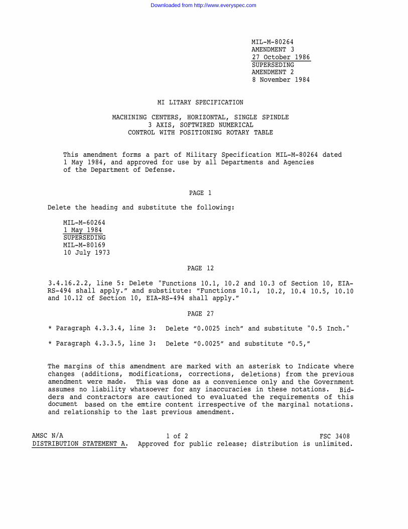
MIL-M-80264AMENDMENT 327 October 1986SUPERSEDINGAMENDMENT 28 November 1984
MI LITARY SPECIFICATION
MACHINING CENTERS, HORIZONTAL, SINGLE SPINDLE3 AXIS, SOFTWIRED NUMERICAL
CONTROL WITH POSITIONING ROTARY TABLE
This amendment forms a part of Military Specification MIL-M-80264 dated1 May 1984, and approved for use by all Departments and Agenciesof the Department of Defense.
PAGE 1
Delete the heading and substitute the following:
MIL-M-602641 May 1984SUPERSEDINGMIL-M-8016910 July 1973
PAGE 12
3.4.16.2.2, line 5: Delete "Functions 10.1, 10.2 and 10.3 of Section 10, EIA-RS-494 shall apply.” and substitute: “Functions 10.1, 10.2, 10.4 10.5, 10.10and 10.12 of Section 10, EIA-RS-494 shall apply.”
PAGE 27
* Paragraph 4.3.3.4, line 3: Delete “0.0025 inch” and substitute "0.5 Inch."
* Paragraph 4.3.3.5, line 3: Delete “0.0025” and substitute “0.5,”
The margins of this amendment are marked with an asterisk to Indicate wherechanges (additions, modifications, corrections, deletions) from the previousamendment were made. This was done as a convenience only and the Governmentassumes no liability whatsoever for any inaccuracies in these notations. Bid-ders and contractors are cautioned to evaluated the requirements of thisdocument based on the emtire content irrespective of the marginal notations.and relationship to the last previous amendment.
AMSC N/A 1 of 2 FSC 3408DISTRIBUTION STATEMENT A. Approved for public release; distribution is unlimited.
Downloaded from http://www.everyspec.com
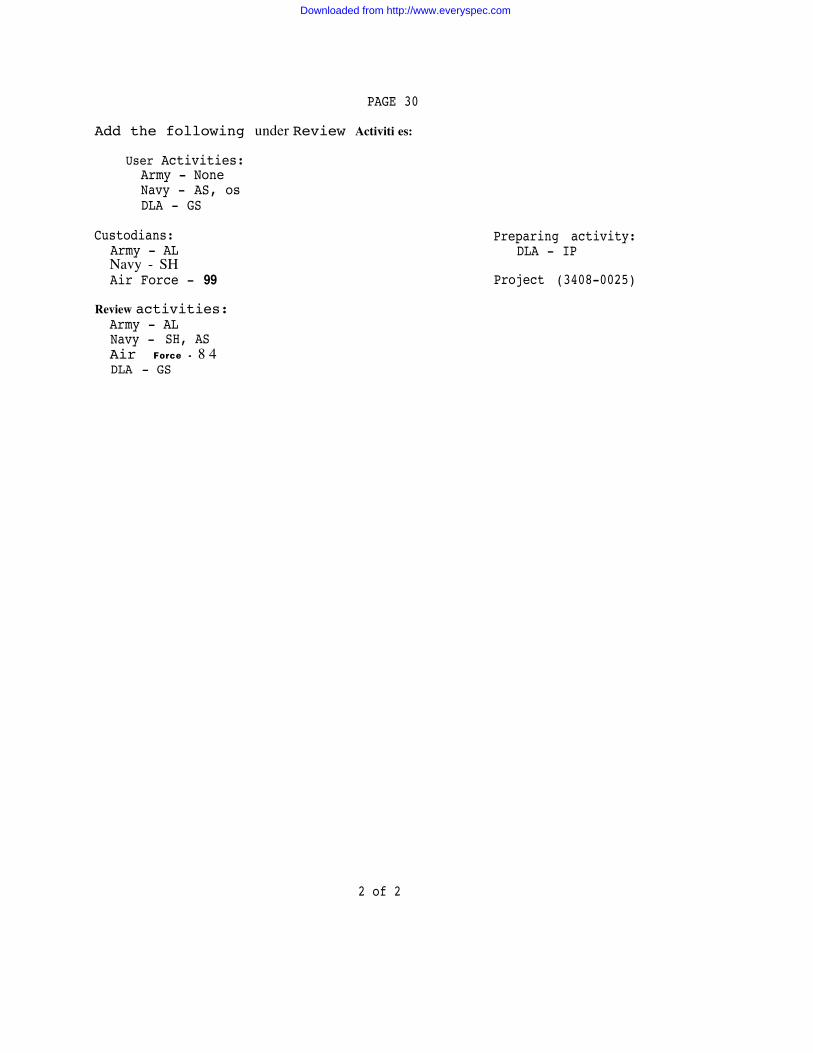
PAGE 30
Add the following under Review Activiti es:
User Activities:Army - NoneNavy - AS, osDLA - GS
Custodians:Army - ALNavy - SHAir Force - 99
Review activities:Army - ALNavy - SH, ASAir Force - 8 4DLA - GS
Preparing activity:DLA - IP
Project (3408-0025)
2 of 2
Downloaded from http://www.everyspec.com

Downloaded from http://www.everyspec.com

Downloaded from http://www.everyspec.com


![[NOT MEASUREMENT SENSITIVE] SUPERSEDING MIL-P-197Heveryspec.com/MIL-SPECS/MIL-SPECS-MIL-DTL/download.php?spec=… · [not measurement sensitive] mil-dtl-197j 9 july 2000 superseding](https://img.pdfslide.us/doc/110x75/5b80c51f7f8b9af7088e17c6/not-measurement-sensitive-superseding-mil-p-not-measurement-sensitive-mil-dtl-197j.jpg)