Embed Size (px)
Citation preview
COVER IN PROGRESS WITH SPINE
P 16
Toward safety and security
in FACE components
P 32
Military tech leadership transitioning to private sector Interview with Ken Peterman, President of Viasat’s Government Systems
@military_cots
MIL-EMBEDDED.COM March 2018 | Volume 14 | Number 2
John McHale DoD funding and COTS suppliers 7
Industry Spotlight Avionics connectors: The need for speed 36
Cyberspace Update DoD cyber service gears up 44
Mil Tech Insider Introducing Gen5 VPX 10
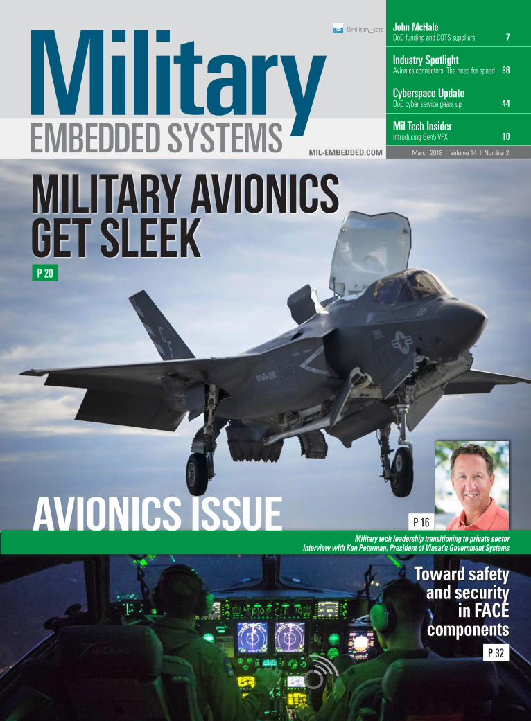
Military avionics get sleek
P 20
AVIONICS ISSUE
4 March 2018 MILITARY EMBEDDED SYSTEMS www.mil-embedded.com
WEB RESOURCESSubscribe to the magazine or E-letter Live industry news | Submit new products http://submit.opensystemsmedia.com
White papers: Read: http://whitepapers.opensystemsmedia.com Submit: http://submit.opensystemsmedia.com
Volume 14 Number 2
All registered brands and trademarks within Military Embedded Systems magazine are the property of their respective owners.
© 2018 OpenSystems Media © 2018 Military Embedded Systems ISSN: Print 1557-3222
ON THE COVER:Top image: An F-35B Lightning II prepares to land on the flight deck of the amphibious assault ship USS America (LHA 6) during The Lightning Carrier Proof of Concept Demonstration. (U.S. Marine Corps photo by Lance Cpl. Dana Beesley/Released.)Bottom image: Air Force Capts. Nikolaus Krause and Josh Bolla are illuminated by the instrument lights aboard a C-17 Globemaster III during exercise Panther Storm at Fort Bragg, North Carolina. Krause and Bolla are pilots assigned to the 8th Airlift Squadron from Joint Base Lewis-McChord, Washington. (Air Force photo by Staff Sgt. Andrew Lee.)
@military_cots
www.linkedin.com/groups/ Military-Embedded-Systems-1864255
COLUMNSEditor’s Perspective 7 Increased DoD budget good news
for COTS suppliers By John McHale
University Update 8 Ready or not, the quantum computing
revolution is here By Sally Cole
Mil Tech Insider10 Introducing Gen 5 VPX By Ivan Straznicky
Cybersecurity Update44 DoD cyber infrastructure moving
steadily toward full operational capability By Mariana Iriarte
Blog45 Five tips for protecting against
wireless KRACK By Russ Doty, Red Hat
DEPARTMENTS 12 Defense Tech Wire
By Mariana Iriarte
42 Editor’s Choice Products
46 Connecting with Mil Embedded By Mil-Embedded.com Editorial Staff
PERSPECTIVES Executive Interview 16 Military tech leadership transitioning
to private sector Interview with Ken Peterman, President of Viasat’s Government Systems division By John McHale, Editorial Director
SPECIAL REPORT Military Avionics Upgrades 20 Military avionics get sleek with
digital glass cockpit instruments and panoramic displays By Sally Cole, Senior Editor
24 Modernizing a serial processing code to obtain optimal performance on an OpenVPX digital signal processing module By Beau Paisley, Arm and Tammy Carter, Curtiss-Wright Defense Solutions
MIL TECH TRENDS Avionics Safety Certification 28 Hardware full disk encryption
technology for military applications using two-layer commercial solutions By Bob Lazaravich and Philip Fulmer, Mercury Systems
32 Toward safety and security in FACE components: High assurance with portability By Benjamin M. Brosgol and Dudrey Smith, Adacore
INDUSTRY SPOTLIGHT Industry Spotlight: Avionics Connectors
36 The need for speed: Avionics connectors evolve to meet today’s bandwidth requirements By Mariana Iriarte, Technology Editor
16
20
32
36
Published by:
www.mil-embedded.comMarch 2018

INVERTERS
The Power Solutions Provider
When it comes to VPX, one company has the most flavorS
ONLY VPXtra® OFFERS THE LARGEST SELECTION OF MIL-SPEC POWER SUPPLIES, WITH MINIMAL COSTS FOR ANY ADDITIONAL CUSTOMIZATIONMost manufacturers offer just a few VPX power supplies off the shelf, with high costs for full-custom. The Behlman VPXtra® series offers the most COTS AC to DC and DC to DC units configured for a wide range of high-end industrial and military applications. All feature our state-of-the-art new engineering standard, Xtra-reliable design and Xtra-rugged construction.
Insist on the leader. Not just VPX, VPXtra®.
AC POWER SUPPLIES / FREQUENCY CONVERTERS
COTS POWER SUPPLIES
: 631-435-0410 : [email protected] : www.behlman.com
5192-BehlmanElectronics_Ad_Military_Embedded_Systems_NOV17.indd 1 10/12/17 9:25 AM
GROUP EDITORIAL DIRECTOR John McHale [email protected]
ASSISTANT MANAGING EDITOR Lisa Daigle [email protected]
SENIOR EDITOR Sally Cole [email protected]
TECHNOLOGY EDITOR Mariana Iriarte [email protected]
DIRECTOR OF E-CAST LEAD GENERATION AND AUDIENCE ENGAGEMENT Joy Gilmore [email protected]
ONLINE EVENTS SPECIALIST Sam Vukobratovich [email protected]
CREATIVE DIRECTOR Steph Sweet [email protected]
SENIOR WEB DEVELOPER Aaron Ganschow [email protected]
WEB DEVELOPER Paul Nelson [email protected]
CONTRIBUTING DESIGNER Joann Toth [email protected]
EMAIL MARKETING SPECIALIST Drew Kaufman [email protected]
VITA EDITORIAL DIRECTOR Jerry Gipper [email protected]
SALES
SALES MANAGER Tom Varcie [email protected] (586) 415-6500
MARKETING MANAGER Eric Henry [email protected] (541) 760-5361
STRATEGIC ACCOUNT MANAGER Rebecca Barker [email protected] (281) 724-8021
STRATEGIC ACCOUNT MANAGER Bill Barron [email protected] (516) 376-9838
STRATEGIC ACCOUNT MANAGER Kathleen Wackowski [email protected] (978) 888-7367
SOUTHERN CAL REGIONAL SALES MANAGER Len Pettek [email protected] (805) 231-9582
SOUTHWEST REGIONAL SALES MANAGER Barbara Quinlan [email protected] (480) 236-8818
NORTHERN CAL STRATEGIC ACCOUNT MANAGER Sean Raman [email protected] (510) 378-8288
ASIA-PACIFIC SALES ACCOUNT MANAGER Helen Lai [email protected]
BUSINESS DEVELOPMENT EUROPE Rory Dear [email protected] +44 (0)7921337498
PRESIDENT Patrick Hopper [email protected]
EXECUTIVE VICE PRESIDENT John McHale [email protected]
EXECUTIVE VICE PRESIDENT Rich Nass [email protected]
CHIEF FINANCIAL OFFICER Rosemary Kristoff [email protected]
EMBEDDED COMPUTING BRAND DIRECTOR Rich Nass [email protected]
EMBEDDED COMPUTING EDITORIAL DIRECTOR Curt Schwaderer [email protected]
TECHNOLOGY EDITOR Brandon Lewis [email protected]
CONTENT ASSISTANT Jamie Leland [email protected]
CREATIVE PROJECTS Chris Rassiccia [email protected]
FINANCIAL ASSISTANT Emily Verhoeks [email protected]
SUBSCRIPTION MANAGER [email protected]
CORPORATE OFFICE 1505 N. Hayden Rd. #105 • Scottsdale, AZ 85257 • Tel: (480) 967-5581
REPRINTS WRIGHT’S MEDIA REPRINT COORDINATOR Wyndell Hamilton [email protected] (281) 419-5725
WWW.OPENSYSTEMSMEDIA.COM
6 March 2018 MILITARY EMBEDDED SYSTEMS www.mil-embedded.com
EVENTS
E-CASTS
ESC Boston April 18-19, 2018Boston, MA www.esc-boston.com
AUVSI XPonential 2018 April 30 – May 3, 2018 Denver, CO www.xponential.org
Enabling Open Architectures and Commonality in Military Sensor Systems Sponsored by Annapolis Microsystems, Kontron, National Instruments, and Mercury Systems ecast.opensystemsmedia.com/791
18 ACCES I/O Products, Inc. mPCIe embedded I/O solutions
41 Acromag – AcroPacks = SWaP-C11 AirBorn – Small, sleek & strong2 Annapolis Micro Systems, Inc. –
For when latency really matters5 Behlman Electronics –
When it comes to VPX, our company has the most flavors
38 Cobham Semiconductor Solutions – Join Cobham in flight with their latest products
23 Data Device Corporation – Your solution provider for connectivity/power/control
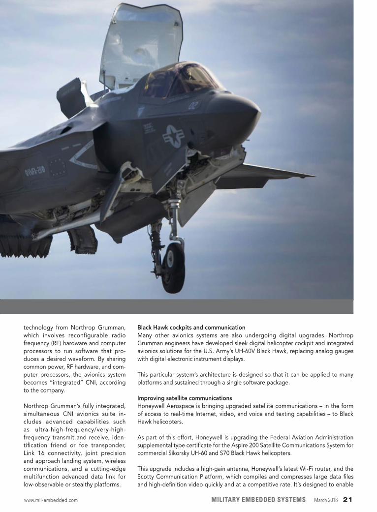
19 Elma Electronic – Integrated sub-systems
3 Extreme Engineering Solutions (X-ES) – Rugged embedded processor boards
37 Mercury Systems – Innovation that’s portable
27 Milpower Source – Mission-ready VPX VITA 62 power solutions
48 Pentek, Inc. – Capture. Record. Real-time. Every time.
11 Phoenix International – Phalanx II: The ultimate NAS
39 Pixus Technologies – Stronger, faster, cooler OpenVPX!
9 Positronic Industries – 1500 MPH. 8.7 Gs. Zero margin of error.
34 Themis Computer – Innovation that’s mobile
15 Vector Electronics & Technology, Inc. – VME/VXS.cPCI chassis, backplanes & accessories
47 VITA Technologies – How will you shape critical and intelligent embedded computing?
Page Advertiser/Ad TitleAD
VERTIS
ER IN
FO
RM
ATIO
N
EDITOR’S PERSPECTIVE
The latest Department of Defense (DoD) fiscal year (FY) 2019 budget request is $686.1 billion, an increase of about five per-cent over the FY 2018 request. This is outstanding news for the warfighters, as they will get more support from a technology standpoint than during recent years where budget cuts and sequestration were the rule. Embedded commercial off-the-shelf (COTS) electronics suppliers will find it pleasing too, as the budget request provides funding for avionics; intelligence, surveillance, and reconnaissance (ISR); electronic warfare (EW); and radar applications.
I talked with three COTS suppliers about the DoD budget and its effect on their businesses, which applications are the best bets for COTS procurement, and the return of predictability to the market in the COTS Confidential roundtable in February’s McHale Report, readable here: http://bit.ly/2tlqPXt.
“The majority of newer weapons systems contain significantly more electronic content than previous generations,” says Sean D’Arcy, Director – Aerospace and Defense – Analog Devices, Inc. “Aside from electronic warfare, radar, and military com-munications systems, we are seeing electronics becoming the key technology in small missiles, guided projectiles, and soldier systems. This is driving greater miniaturization and integra-tion in packages that can survive extreme environments and mechanical shock.”
Another bellwether showing the strength of the COTS market is the size of the DoD’s Research, Development, Test, and Evaluation (RDT&E) budget, as that funds much of the tech-nology development the electronics sector provides. For FY 2019 the requested funding is $90.6 billion, an increase of $18.8 billion over the FY 2018 enacted budget.
“As the RDT&E budget increases, available funding to the defense electronics sector – and the military embedded com-puting market – in creases, but the effects are not immediately reflected in the bottom line of any company,” explains Doug Patterson, Vice President, Military & Aerospace Business Sector at Aitech Defense Systems. “There is a long process, and a natural lag time, from the president’s budget request, through the varied congressional budget hearings, then to budget res-olutions, and on to the Defense Appropriations Bill, which is voted into law. From there, the various armed services have to produce approved program spending budget increases for this to then flow down to the various prime contractors and, in turn, to their subcontractors.”
The best bets for embedded electronics procurement continue to be those that require intense signal-processing capability, such as radar, EW, and persistent surveillance applications.
“There are quite a lot of good opportunities right now, but the fastest growth at a market segment level is in EW, antidrone systems, and UAVs [unmanned aerial vehicles],” says Manuel Uhm, Director of Marketing, Ettus Research, a National Instru- ments company. “While electronic warfare has been in growth mode for several years now due to the increasing need for spectrum dominance over enemy forces, the proliferation of drones and UAVs has also resulted in new means for guerilla warfare, which necessitate ways to counter them.
“Other emerging areas of opportunity for COTS vendors include cybersecurity and artificial intelligence (AI)/machine learning (ML),” he continues. “Cybersecurity continues to be a hot topic as more hacks and security vulnerabilities become known. ML is a very hot emerging technology to address many issues related to autonomous systems and big data, among others.”
Commercial parts obsolescence drives many of these oppor-tunities as the military needs to constantly refresh electronic systems to continually counter ever more complex threats.
“At the moment, there is a great deal of effort around updating existing platforms due to the semiconductor industry’s self-imposed penchant of obsoleting components, with no regard whatsoever for the affects upon our national security and war-fighter support,” Patterson notes. “Next are new designs and new programs, then sustainment efforts.”
For now, the increased funding for RDT&E, new programs, and sustainment efforts is bringing some certainty back to what has been an uncertain market.
“From my perspective, time and again, accurately forecasting sales has proven to be part experience, part customer feed-back, part DoD program funding tracking, and part black magic,” Patterson notes. “What has been getting easier over the last year, though, is predicting the effects of program funding uncertainty and risks, i.e., with market and consumer confidence increases, the risks of program cancellation are lower – for now, anyway, as this can change in a heartbeat if you’re not watching closely.”
The Trump administration’s hawkish approach to defense spending should continue for the remainder of his first term, ensuring predictability till at least 2020.
The challenge for COTS suppliers face now “may well be keeping up with the demand. Embedded COTS systems pro-vide a strong baseline, but will require customization for surviv-ability, security, and military integration, which will tax resources across the industry,” D’Arcy says.
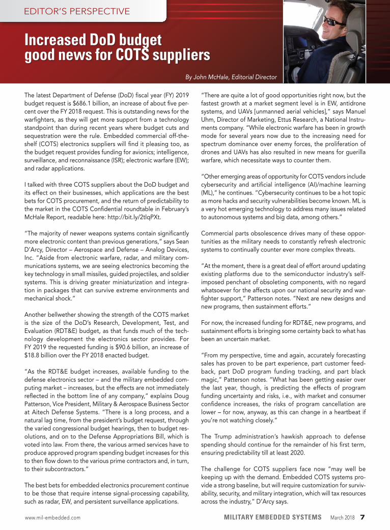
By John McHale, Editorial Director
Increased DoD budget good news for COTS suppliers
www.mil-embedded.com MILITARY EMBEDDED SYSTEMS March 2018 7
8 March 2018 MILITARY EMBEDDED SYSTEMS www.mil-embedded.com
A National Science Foundation (NSF) expedition project it calls “Enabling Practical-Scale Quantum Computing” (EPiQC) aims to bridge the gap between quantum designs currently in use and the algorithms necessary to fully embrace their power.
In an effort to help accelerate the poten-tial of quantum computing, NSF recently launched EPiQC, a $10 million expedition into quantum computing. The project is led by the University of Chicago, which is bringing together experts in algorithms, software, and computer architecture from MIT, Princeton, Georgia Tech, and the University of California, Santa Barbara.
Quantum machines may soon be capable of performing complex com-putations that can advance artificial intelligence, computer security, chem-istry, and other fields in ways that are extremely difficult or beyond the scope of today’s computers.
IBM, Intel, and Google all recently un- veiled new quantum computing proto- types approaching 50 quantum bits (qubits) – a qubit is a single bit of quantum information – a milestone in the quest to create machines capable of producing unprecedented discoveries.
Despite these advances, there remains a huge gap between the quantum designs currently in use and the algorithms nec-essary to make full use of their power. The EPiQC project will tackle this por-tion of the puzzle.
To do this, the researchers will focus on developing new algorithms and soft-ware and hardware designs tailored to key properties of quantum technologies that are capable of 100 to 1,000 qubits.
“We want to close the gap enough that we can do something about these promising machines,” says Frederic Chong, Seymour Goodman professor in
the Department of Computer Science at the University of Chicago and lead inves-tigator on EPiQC.
EPiQC will work developing these ele-ments together to take full advantage of new quantum machines. Importantly, the collaboration will also involve part-ners from industry and other universities to form a consortium that can share research ideas and new tools as they are developed.
“Without a coordinated effort such as EPiQC, these computers will come out and no one will be able to program them and they’ll need a much larger machine to do the computation they want to do,” notes Diana Franklin, dir- ector of Computer Science Education at University of Chicago STEM Education and a research associate professor at the university.
How does quantum computing work? Its basic premise is that qubits can occupy the superposition of states, rather than the binary 1 or 0 of classical computing bits. This means that each additional qubit doubles the computing power of a machine and produces exponen-tial gains. Scientists could use these machines to run simulations and solve equations too complex for classical computers – and possibly reveal break-throughs in cryptography, transportation optimization, and many other fields.
Many algorithms designed so far to exploit quantum advantages require the use of much more powerful machines than will be available in the near term. Scientists also lack the software needed to adapt these algorithms for practical use on actual machines, as well as the infrastructure tools needed for program-ming these new technologies.
“The big missing piece in quantum com-puting is what we can do with it that’s useful,” Chong says. “We want to think
about it in very practical terms. What happens when you have a small number of devices, you can only run them for a short amount of time, and you have noise and errors? Will the algorithms work then, and how can we change them to make them work better? And how can we change the machine to make the algorithms work better?”
EPiQC will play “an essential role in researching efficient codesign of algo-rithms, software and devices, as well as creating tools to put quantum in front of a wider audience for even greater quantum programming creativity, and eventual breakthrough quantum appli-cations,” says Jay Gambetta, manager of Quantum Information and Computing at IBM Research, which offers a hands-on quantum computing experience with its 5- and 16-qubit IBM Q Experience devices and QISKit software framework. “EPiQC will also develop curricula to help train a much-needed workforce to drive quantum computing forward.”
Overall, EPiQC’s goal is not only to pro-duce tools, educate people, and grow the community, “but also to help people appreciate the important problems to be solved here and inspire people to work on them,” Chong says.
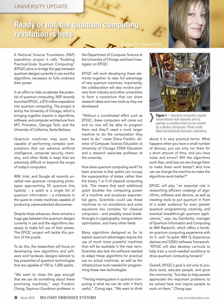
Figure 1 | Quantum computers require temperatures near absolute zero to operate, a condition that can be created by a dilution refrigerator. Photo credit: Nate Earnest/David Schuster Laboratory.
›
By Sally Cole, Senior Editor
UNIVERSITY UPDATE
Ready or not, the quantum computing revolution is here
When you’re hurtling headlong past sonic breach, you can’t afford a systems failure. At Positronic, we build high reliability power and signal connectors. But our true call is to provide certainty. Rock solid, mission-critical performance upon which you can bank life and limb, family, fortune, freedom. We consider it an honor. We consider it an inviolable trust.
POSITRONIC. THE SCIENCE OF CERTAINTY. // www.connectpositronic.com/mes_mar2018
1500 MPH.8.7 Gs.Zero Margin of Error.
SoC_Pilot_8x10.875.indd 1 5/2/18 9:35 AM
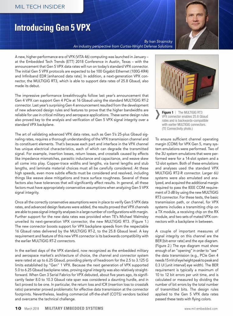
A new, higher-performance era of VPX (VITA 46) computing was launched in January – at the Embedded Tech Trends (ETT) 2018 Conference in Austin, Texas – with the announcement that Gen 5 VPX data rates will run on today’s standard VPX connector. The initial Gen 5 VPX protocols are expected to be 100 Gigabit Ethernet (100G-KR4) and Infiniband EDR [enhanced data rate]. In addition, a next-generation VPX con-nector, the MULTIGIG RT3, which is able to support data rates of 25.8 Gbaud, also made its debut.
The impressive performance breakthroughs follow last year’s announcement that Gen 4 VPX can support Gen 4 PCIe at 16 Gbaud using the standard MULTIGIG RT-2 connector. Last year’s surprising Gen 4 announcement resulted from the development of new advanced design rules and features to prove that the higher bandwidths are reliable for use in critical military and aerospace applications. These same design rules also proved key to the analysis and verification of Gen 5 VPX signal integrity over a standard VPX backplane.
The art of validating advanced VPX data rates, such as Gen 5’s 25-plus Gbaud sig-naling rates, requires a thorough understanding of the VPX transmission channel and its constituent elements. That’s because each part and interface in the VPX channel has unique electrical characteristics, each of which can degrade the transmitted signal. For example, insertion losses, return losses, and crosstalk caused by effects like impedance mismatches, parasitic inductance and capacitance, and weave skew all come into play. Copper-trace widths and lengths, via barrel lengths and stub lengths, and laminate material choices must all be carefully considered. At these high speeds, even more subtle effects must be considered and resolved, including things like weave skew mitigations and trace surface roughness. Several of these factors also have tolerances that will significantly affect results. In general, all these factors must have appropriately conservative assumptions when analyzing Gen 5 VPX signal integrity.
Once all the correctly conservative assumptions were in place to verify Gen 5 VPX data rates, and advanced design features were added, the results proved that VPX channels are able to pass signal-integrity analyses in a large number of configurations with margin. Further support for the new data rates was provided when TE’s Michael Walmsley unveiled its next-generation VPX connector, the new MULTIGIG RT3. (Figure 1.) The new connector boosts support for VPX backplane speeds from the respectable 16 Gbaud rates delivered by the MULTIGIG RT-2, to the 25.8 Gbaud level. A key requirement and feature of this new VPX connector is its backwards compatibility with the earlier MULTIGIG RT-2 connectors.
In the earliest days of the VPX standard, now recognized as the embedded military and aerospace market’s architecture of choice, the channel and connector system were rated at up to 6.25 Gbaud, providing plenty of headroom for the 2.5 to 3.125 G limits established by “Gen” 1 VPX. Because the next generation of VPX supported 5.0 to 6.25 Gbaud backplane rates, proving signal integrity was also relatively straight-forward. When Gen 3 Serial Fabrics for VPX debuted, about five years ago, its signifi-cantly faster 8.0 to 10.3 Gbaud rate span was considered a daunting hurdle, and in fact proved to be one. In particular, the return loss and ICR (insertion loss to crosstalk ratio) parameter proved problematic for effective data transmission at the connector footprints. Nevertheless, leading commercial off-the-shelf (COTS) vendors tackled and overcame the technical challenge.
By Ivan Straznicky An industry perspective from Curtiss-Wright Defense Solutions
MIL TECH INSIDER
Introducing Gen 5 VPX
To ensure sufficient channel operating margin (COM) for VPX Gen 5, many sys- tem emulations were performed. Two of the 3U system emulations that were per-formed were for a 14-slot system and a 12-slot system. Both of these emulations and analyses used the standard VPX MULTIGIG RT2-R connector. Larger 6U systems were also emulated and ana-lyzed, and acquired the additional margin required to pass the IEEE COM require-ment of 3 dB by using the new MULTIGIG RT3 connector. For these tests, the basic transmission path, or channel, for VPX systems includes a transmitting chip on a TX module, a receiving chip on the RX module, and two sets of mated VPX con-nectors with a backplane in between.
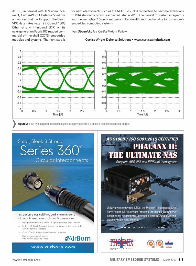
A couple of important measures of signal integrity on this channel are the BER [bit-error rate] and the eye diagram. (Figure 2.) The eye diagram must show enough of an “opening” in order to “see” the data transmission (e.g., PCIe Gen 4 needs 15 mV of eye height peak to peak and 0.3 UI [unit interval] eye width). The BER requirement is typically a maximum of 10 to 12 bit errors per unit time, and is calculated or measured by dividing the number of bit errors by the total number of transmitted bits. The design rules applied to the Gen 5 VPX data rates passed these tests with flying colors.
10 March 2018 MILITARY EMBEDDED SYSTEMS www.mil-embedded.com
Figure 1 | The MULTIGIG RT3 VPX connector enables 25.8 Gbaud rates and is backwards-compatible with earlier MULTIGIG connectors. (TE Connectivity photo.)
›
At ETT, in parallel with TE’s announce-ment, Curtiss-Wright Defense Solutions announced that it will support the Gen 5 VPX data rates (e.g., 25 Gbaud 100G Ethernet and Infiniband EDR) on its next-generation Fabric100 rugged com-mercial off-the-shelf (COTS) embedded modules and systems. The next step is
for new interconnects such as the MULTIGIG RT 3 connectors to become extensions to VITA standards, which is expected later in 2018. The benefit for system integrators and the warfighter? Significant gains in bandwidth and functionality for tomorrow’s embedded computing systems.
Ivan Straznicky is a Curtiss-Wright Fellow.
Curtiss-Wright Defense Solutions • www.curtisswrightds.com
Figure 2 | An eye diagram measures signal integrity to ensure sufficient channel operating margin.›AS 9100D / ISO 9001:2015 CERTIFIED
PHALANX II: THE ULTIMATE NAS
Supports AES-256 and FIPS140-2 encryption
Utilizing two removable SSDs, the Phalanx II is a rugged Small Form Factor (SSF) Network Attached Storage (NAS) file server designed for manned and unmanned airborne, undersea and ground mobile applications.
w w w . p h e n x i n t . c o m
PHX_OSP_3.375_4.875.indd 1 1/22/18 11:36 AM
Series 360®
Introducing our NEW rugged, ultraminiature circular interconnect solution & assemblies
— High performance in a smaller & lighter package than D38999
— Push/Pull & Quick-DeMate® versions available; both interoperable with the same receptacle
— Quick-Clean® & High-Speed versions available
— Board-mount, panel-mount, cable & flex assembly ready
www.airborn.com
Circular Interconnects
Small, Sleek & Strong
www.mil-embedded.com MILITARY EMBEDDED SYSTEMS March 2018 11
Plug-in smartphone app enables military parachutists to land with greater precisionA team of engineers at Draper Laboratories recently filed a patent for a smartphone app that automatically detects when parachutists make the critical transition from the plane to being under their parachute canopy.
The app – which operates as a plug-in to a smartphone, with the first version available for the Android platform – is designed for parachutists to view the terrain below them, the location of the jump team around them, and the designated landing point.
The app is also equipped to track the parachutists by sensing the moment they leave the plane; at that point, the app auto-matically switches navigation modes, enabling the parachutist to focus on maneuvering their parachute rather than adjusting the app.
U.S., allies order upgrades to Patriot missileThe U.S. military and allied forces will upgrade their missile defense capabilities under a $524 million contract modifica-tion for production and delivery of Lockheed Martin’s Patriot Advanced Capability-3 (PAC-3) and PAC-3 Missile Segment Enhancement (PAC-3 MSE) interceptors.
The contract modification adds on to the $944 million contract awarded in December 2017 for PAC-3 and PAC-3 MSE pro-duction and delivery. The PAC-3 is a high-velocity interceptor designed to defend forces against incoming threats, including tactical ballistic missiles, cruise missiles, and aircraft.
According to materials from Lockheed Martin, PAC-3 provides missile defense capabilities for 11 nations at the moment: the U.S., Germany, Kuwait, Japan, Qatar, the Republic of Korea, Kingdom of Saudi Arabia, Taiwan, the Netherlands, United Arab Emirates, and Romania.
DEFENSE TECH WIRE
By Mariana Iriarte, Associate Editor
NEWS | TRENDS | DOD SPENDS | CONTRACTS | TECHNOLOGY UPDATES
NEWS
IARPA launches project to detect complex activities using videoThe Intelligence Advanced Research Projects Activity (IARPA) announced that it will mount a research effort to develop Deep Intermodal Video Activity (DIVA) to help narrow the gap between human visual perception and a computer’s ability to automatically recognize activities.
The aim of DIVA, according to an IARPA statement, is to advance state-of-the-art artificial visual perception and automate video monitoring. The technology could be used in such areas as detection of potential threats outside secure government facili-ties or in high-traffic public transportation areas.
IARPA selected six performer teams using the Broad Agency Announcement process to develop new cutting-edge research on DIVA. Kitware Inc. and the National Institute of Standards and Technology are tasked with collecting research data and performing independent testing of the new systems.
Figure 2 | A smartphone app developed by Draper is designed to help military parachutists land with higher accuracy. Photo courtesy of the U.S. Army.
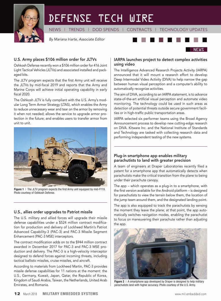
Figure 1 | The JLTV program expects the first Army unit equipped by mid-FY19. Photo courtesy of Oshkosh Defense.
U.S. Army places $106 million order for JLTVsOshkosh Defense recently won a $106 million order for 416 Joint Light Tactical Vehicles (JLTVs) and associated installed and pack-aged kits.
The JLTV program expects that the first Army unit will receive the JLTVs by mid-fiscal 2019 and reports that the Army and Marine Corps will achieve initial operating capability in early fiscal 2020.
The Oshkosh JLTV is fully compliant with the U.S. Army’s mod-ular Long Term Armor Strategy (LTAS), which enables the Army to reduce unnecessary wear and tear on the armor by removing it when not needed; allows the service to upgrade armor pro-tection in the future; and enables users to transfer armor from unit to unit.
12 March 2018 MILITARY EMBEDDED SYSTEMS www.mil-embedded.com
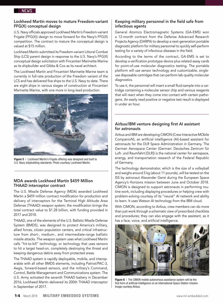
MDSI: $26 million contract for cooling tank electronics, personnelMeggitt Defense Systems, Inc. (MDSI, a subsidiary of Meggitt PLC) won a $26 million contract to provide thermal management systems (TMS) to General Dynamics Land Systems (Sterling Heights, Michigan) for the M1A2 SEPv3 and M1A2 KSA main battle tanks.
The MDSI contract supports the contract recently given to GDLS by the U.S. government for the upgrade of 786 M1 Abrams tanks for the U.S. Army and FMS contracts.
To date, say MDSI officials, the company has produced more than 2,400 TMSs for the Abrams tank program. The systems provide active cooling to the sensitive upgraded electronics used in the Abrams tanks, plus heat and air conditioning for the crew.
DoD Network Defense Headquarters reaches full operational capabilityThe Joint Force Headquarters Department of Defense Infor- mation Network (JFHQ-DoDIN) reports that it has achieved full operational capability.
According to DoD reports, the JFHQ-DoDIN reached the operational milestone – counting roughly 15,000 networks with three million users – following three years of building capacity and capability to secure, operate, and defend the DoDIN, a global network enabling military operations across all warfighting domains.
To reach full operational capability, JFHQ-DoDIN participated in a number of service, Joint Staff, cybercom, and additional combatant command exercises in support of mission out-comes; it also managed daily operations that searched for and countered significant actual cyberthreats. All 133 Cyber Mission Force teams are on track to achieve full operational capability by September, officials said.
DoD awards cloud solutions, services contract with $950 million ceilingGlobal cloud systems integrator REAN Cloud recently finalized a five-year contract with the U.S. Department of Defense (DoD) for up to $950 million, in a deal aimed at enabling agencies within DoD to procure cloud solutions and services directly from REAN Cloud in a new, streamlined process.
REAN Cloud worked with Defense Innovation Unit Experimental (DIUx) – a DoD organization tasked with accelerating commer-cial innovation to the U.S. military – in order to facilitate pro-totyping and procurement of the full range of cloud adoption requirements, from infrastructure as a service (IaaS) to applica-tion assessments, migrations, and operations.
The newly announced production Other Transaction (OT) con-tract is modeled on an innovative OT prototype project for the U.S. Transportation Command (USTRANSCOM), DoD’s first large-scale infrastructure assessment and cloud migration, which was completed by REAN Cloud last year. As part of the production OT award, REAN Cloud’s processes will enable USTRANSCOM and other DoD organizations quickly migrate legacy applications to a government-approved, commercial cloud environment of their choice.
NEWS
Figure 4 | Abrams tank. Photo courtesy of the U.S. Army/ Capt. Malcolm Rios, 3rd ABCT Public Affairs, 4th Inf. Div.
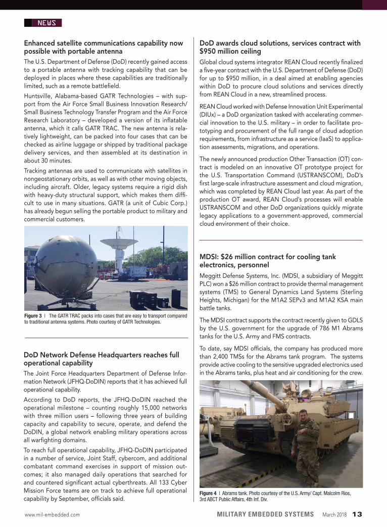
Figure 3 | The GATR TRAC packs into cases that are easy to transport compared to traditional antenna systems. Photo courtesy of GATR Technologies.
DEFENSE TECH WIREEnhanced satellite communications capability now possible with portable antennaThe U.S. Department of Defense (DoD) recently gained access to a portable antenna with tracking capability that can be deployed in places where these capabilities are traditionally limited, such as a remote battlefield.
Huntsville, Alabama-based GATR Technologies – with sup-port from the Air Force Small Business Innovation Research/Small Business Technology Transfer Program and the Air Force Research Laboratory – developed a version of its inflatable antenna, which it calls GATR TRAC. The new antenna is rela-tively lightweight, can be packed into four cases that can be checked as airline luggage or shipped by traditional package delivery services, and then assembled at its destination in about 30 minutes.
Tracking antennas are used to communicate with satellites in nongeostationary orbits, as well as with other moving objects, including aircraft. Older, legacy systems require a rigid dish with heavy-duty structural support, which makes them diffi-cult to use in many situations. GATR (a unit of Cubic Corp.) has already begun selling the portable product to military and commercial customers.
www.mil-embedded.com MILITARY EMBEDDED SYSTEMS March 2018 13
MDA awards Lockheed Martin $459 Million THAAD interceptor contractThe U.S. Missile Defense Agency (MDA) awarded Lockheed Martin a $459 million contract modification for production and delivery of interceptors for the Terminal High Altitude Area Defense (THAAD) weapon system; the modification brings the total contract value to $1.28 billion, with funding provided in 2017 and 2018.
THAAD, one of the elements of the U.S. Ballistic Missile Defense System (BMDS), was designed to protect America’s military, allied forces, citizen population centers, and critical infrastruc-ture from short-, medium-, and intermediate-range ballistic missile attacks. The weapon system uses what Lockheed Martin calls “hit-to-kill” technology, or technology that uses sensors to hit a target head-on, completely destroying the threat and keeping dangerous debris away from protected areas.
The THAAD system is rapidly deployable, mobile, and interop-erable with all other BMDS elements, including Patriot/PAC-3, Aegis, forward-based sensors, and the military’s Command, Control, Battle Management and Communications system. The U.S. Army activated the seventh THAAD battery in December 2016; Lockheed Martin delivered its 200th THAAD interceptor in September of 2017.
Keeping military personnel in the field safe from infectious agentsGeneral Atomics Electromagnetic Systems (GA-EMS) won a 12-month contract from the Defense Advanced Research Projects Agency (DARPA) to develop a next-generation portable diagnostic platform for military personnel to quickly self-perform testing for a variety of infectious diseases in the field.
According to the terms of the contract, GA-EMS is set to develop a verification prototype device plus related assay cards for point-of-use molecular diagnostics testing. The portable platform will use sensor technology and customizable, single-use disposable cartridges that can perform lab-quality molecular diagnostics.
To use it, the personnel will insert a small fluid sample into a car-tridge containing a molecular sensor chip and various reagents that will react when they come into contact with certain patho-gens. An easily read positive or negative test result is displayed in under an hour.
NEWS
Figure 6 | The CIMON mobile autonomous assistance system will be the first form of artificial intelligence on an International Space Station mission. Image courtesy Airbus.
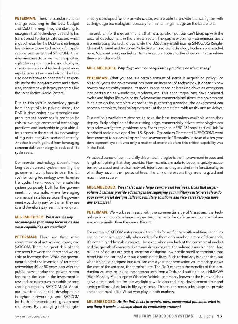
Figure 5 | Lockheed Martin’s Frigate offering was designed and built to U.S. Navy shipbuilding standards. Photo courtesy Lockheed Martin.
Airbus/IBM venture designing first AI assistant for astronautsAirbus and IBM are developing CIMON (Crew Interactive MObile CompanioN), an artificial intelligence (AI)-based assistant for astronauts for the DLR Space Administration in Germany. The German Aerospace Center (German: Deutsches Zentrum für Luft- und Raumfahrt [DLR]) is the national center for aerospace, energy, and transportation research of the Federal Republic of Germany.
The technology demonstrator, which is the size of a volleyball and weighs around 5 kg (about 11 pounds), will be tested on the ISS by astronaut Alexander Gerst during the European Space Agency’s Horizons mission between June and October 2018. CIMON is designed to support astronauts in performing rou-tine work, including displaying procedures or helping crew with problem-solving courtesy of its “neural” AI network and ability to learn. It uses Watson AI technology from the IBM cloud.
With CIMON, according to Airbus, crew members can do more than just work through a schematic view of prescribed checklists and procedures; they can also engage with the assistant, as it has a face, voice, and artificial intelligence.
Lockheed Martin moves to mature Freedom-variant FFG(X) conceptual designU.S. Navy officials approved Lockheed Martin’s Freedom-variant Frigate (FFG(X)) design to move forward for the Navy’s FFG(X) competition. The contract to mature the conceptual design is valued at $15 million.
Lockheed Martin submitted its Freedom-variant Littoral Combat Ship (LCS) parent design in response to the U.S. Navy’s FFG(X) conceptual design solicitation with Fincantieri Marinette Marine as its shipbuilder and Gibbs & Cox as its naval architect.
The Lockheed Martin and Fincantieri Marinette Marine team is currently in full-rate production of the Freedom variant of the LCS and has delivered five ships to the U.S. Navy to date. There are eight ships in various stages of construction at Fincantieri Marinette Marine, with one more in long-lead production.
14 March 2018 MILITARY EMBEDDED SYSTEMS www.mil-embedded.com
MIL-EMBEDDED: Please provide a brief description of your responsibility within Viasat and your group’s role within the company.
PETERMAN: Viasat was founded more than 30 years ago by three young engineers working out of a garage to what it is now: a $1.6 billion company with more than 4,500 global employees. There are three main business segments to the company: Commercial Networks, which oversees the development and deployment of our satellite systems, from the satellites themselves to the ground and cloud infrastruc-ture, to the customer premise equipment; Commercial Broadband Services, which delivers high-speed, high-quality satellite broadband internet to more than 600,000 homes across the U.S., and more than 2,000 commercial airline flights daily; and the Government Systems division, which is underneath my leadership team. We look to leverage the same technology across the commercial and government market domains. Under the government side, we provide solutions for satellite communica-tions (SATCOM), cyber, networking, antennas, and tactical data links.
Internally, Viasat is a not a traditional defense company. We are not big on organiza-tional charts, but function much as the founders did when they were operating out of [cofounder and CEO] Mark Dankberg’s garage. In fact, Mark is still a central develop-mental engineer and has an open door with everyone in the company.
MIL-EMBEDDED: The proposed increases in the administration’s DoD budget request are well documented. What does this mean for Viasat and the applications it serves? Are you seeing positive funding growth today and down the road from your military customers?
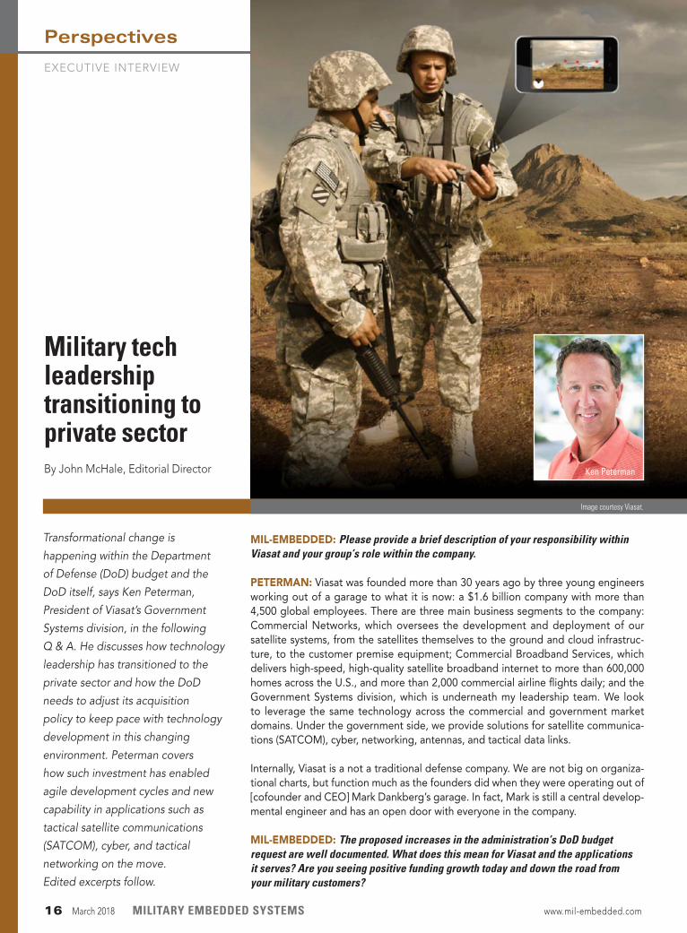
Transformational change is
happening within the Department
of Defense (DoD) budget and the
DoD itself, says Ken Peterman,
President of Viasat’s Government
Systems division, in the following
Q & A. He discusses how technology
leadership has transitioned to the
private sector and how the DoD
needs to adjust its acquisition
policy to keep pace with technology
development in this changing
environment. Peterman covers
how such investment has enabled
agile development cycles and new
capability in applications such as
tactical satellite communications
(SATCOM), cyber, and tactical
networking on the move.
Edited excerpts follow.
Military tech leadership transitioning to private sectorBy John McHale, Editorial Director
Image courtesy Viasat.
Ken Peterman
EXECUTIVE INTERVIEW
Perspectives
16 March 2018 MILITARY EMBEDDED SYSTEMS www.mil-embedded.com
PETERMAN: There is transformational change occurring in the DoD budget and DoD thinking. They are starting to recognize that technology leadership has transitioned to the private sector, which is good news for the DoD as it no longer has to invent new technology for appli-cations such as tactical SATCOM. It can ride private-sector investment, exploiting agile development cycles and deploying a new generation of technology at more rapid intervals than ever before. The DoD also doesn’t have to bear the full respon-sibility for the long-term costs and sched-ules, consistent with legacy programs like the Joint Tactical Radio System.
Due to this shift in technology growth from the public to private sector, the DoD is developing new strategies and procurement processes in order to be able to leverage commercial technology, practices, and leadership to gain ubiqui-tous access to the cloud, take advantage of big-data analytics, and add security. Another benefit gained from leveraging commercial technology is reduced life cycle costs.
Commercial technology doesn’t have long development cycles, meaning the government won’t have to bear the full cost for using technology over its entire life cycle, like it would for a satellite system purposely built for the govern-ment. For example, when leveraging commercial satellite services, the govern-ment would only pay for it when they use it, and therefore pay less in the long run.
MIL-EMBEDDED: What are the key technologies your group focuses on and what capabilities are trending?
PETERMAN: There are three main areas: terrestrial networking, cyber, and SATCOM. There is a great deal of tech crossover between the three and we are able to leverage that. While the govern-ment funded the invention of terrestrial networking 40 or 50 years ago with the public purse, today the private sector has taken the lead in the investment in new technologies such as mobile phones and high-capacity SATCOM. At Viasat, our investments include developments in cyber, networking, and SATCOM for both commercial and government customers. By leveraging technologies
initially developed for the private sector, we are able to provide the warfighter with cutting-edge technologies necessary for maintaining an edge on the battlefield.
The problem for the government is that its acquisition policies can’t keep up with the pace of development in the private sector. The gap is widening – commercial users are embracing 5G technology while the U.S. Army is still issuing SINCGARS [Single-Channel Ground and Airborne Radio System] radios. Technology leadership is needed here. We want every warfighter to have secure access to the cloud no matter where they are in the world.
MIL-EMBEDDED: Why do government acquisition practices continue to lag?
PETERMAN: What you see is a certain amount of inertia in acquisition policy. For 50 to 60 years the government has been an inventor of technology. It doesn’t know how to buy a turnkey service. Its model is one based on breaking down an ecosystem into parts such as waveforms, modems, etc. This encourages long developmental cycles and higher life cycle costs. By leveraging commercial solutions, the government is able to do the complete opposite; by purchasing a service, the government can access a complete, functioning system all at the same time, with no risk and no delays.
Our nation’s warfighters deserve to have the best technology available when they deploy. Early adoption of these cutting-edge, commercially-driven technologies can help solve warfighters’ problems now. For example, our PRC-161 small tactical Link-16 handheld radio developed for U.S. Special Operations Command (USSOCOM) went from concept to successful operational assessment in 18 months. Instead of a ten-year development cycle, it was only a matter of months before this critical capability was in the field.
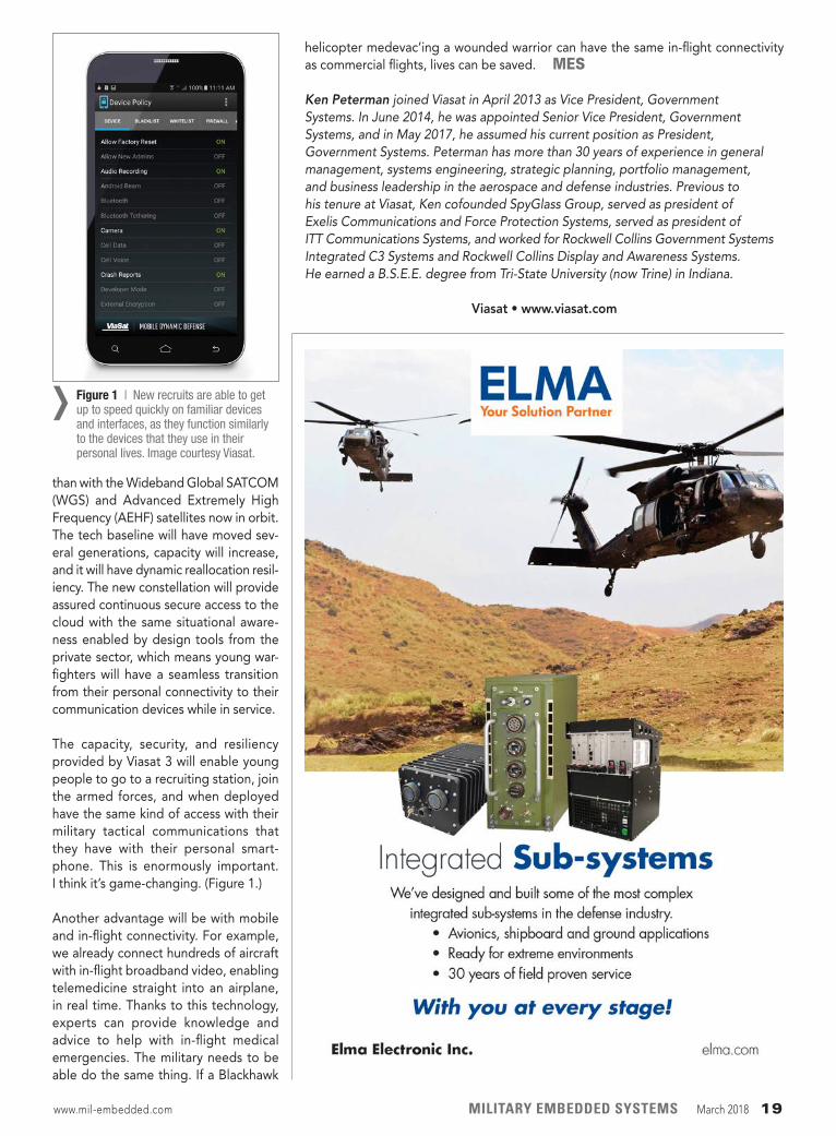
An added bonus of commercially driven technologies is the improvement in ease and length of training that they provide. New recruits are able to become quickly accus-tomed to cloud and tactical network interfaces, as they are similar in functionality to what they have in their personal lives. The only difference is they are encrypted and much more secure.
MIL-EMBEDDED: Viasat also has a large commercial business. Does that larger-volume business provide advantages for supplying your military customers? How do your commercial designs influence military solutions and vice versa? Do you have any examples?
PETERMAN: We work seamlessly with the commercial side of Viasat and the tech-nology is common to a large degree. Requirements for defense and commercial are also more similar than they are different.
For example, SATCOM antennas and terminals for warfighters with real-time capability can be expensive especially when orders for them only number in tens of thousands. It’s not a big addressable market. However, when you look at the commercial market and the growth of connected cars and driverless cars, the volume is much higher. Here millions of dollars are being spent on designing low-profile satellite terminals that blend into the car roof without disturbing its lines. Such technology is expensive, but when it’s being designed into a million cars a year that production volume brings down the cost of the antenna, the terminal, etc. The DoD can reap the benefits of that pro-duction volume; by taking the antenna tech from a Tesla and putting it on a HMMWV [High Mobility Multipurpose Wheeled Vehicle, commonly known as the Humvee] they solve a tech problem for the warfighter while also reducing development time and saving millions of dollars in life cycle costs. This an enormous advantage for private sector companies like Viasat who play in both markets.
MIL-EMBEDDED: As the DoD looks to acquire more commercial products, what is one thing it needs to change about its purchasing process?
www.mil-embedded.com MILITARY EMBEDDED SYSTEMS March 2018 17
PETERMAN: Open standards from the DoD perspective need to specify the “what” and not the “how.” For many technologies the DoD uses, such as smartphones, the standards need to be at the higher networking level, not the inner workings of the device. When the DoD specifies the “how” in addition to the “what” it is limiting the ability of the private sector to provide innovative solutions. The “what” is the capa-bility you need, not the “how,” which only reduces the number of cyber, SATCOM, or other solutions industry can provide.
For example, if the government needs a new transport vehicle that can be easily re fueled anywhere in the world, their specification should be limited to the capability – global refueling – and not specify how the auto industry will design it.
MIL-EMBEDDED: When one attends a trade show such as the Consumer Electronics Show (CES) or others like it, one can’t help but notice there is a lot less gray hair at these events than at military technology events such as the large Army and Navy shows. Does the military-electronics industry have a recruitment challenge on its hands?
PETERMAN: I think the defense indus-trial base does have a significant talent-acquisition problem. It’s even deeper than that as it’s a relevancy problem. Military purpose-built terrestrial networking and SATCOM tech is becoming less and less relevant to young engineers. This is the reason you see gray hair, because young engineers don’t view it as cool, interesting stuff. The traditional defense company is very regimented, and under-standably so, with certain government accountability required, but they lack the openness and collaborative environ-ments that enable Google and Facebook to attract talent. Which is why a place like Viasat, with its innovative business model, enables a young engineer to collaborate with the founder without any walls, keeps it evergreen.
At Viasat I see tons of interns, plus new college grads joining the company every year. We think differently and are not encumbered with the scar tissue of the last 20 years in the defense industry, so we don’t have the recruitment challenge traditional defense companies do. Much of their leadership came out of the DoD. Once their service is complete, many offi-cers join the traditional defense primes when they move to the private sector. In contrast, we [at Viasat] have talent cen-ters all over the world, recruiting exper-tise from multiple markets.
MIL-EMBEDDED: Looking forward, what disruptive technology/innovation will be a game changer in the military tactical communications space? Predict the future.
PETERMAN: Hands down, it will be when the ViaSat-3 satellite constellation becomes operational. It will enable the DoD to be orders of magnitude more capable with its performance envelope
Perspectives EXECUTIVE INTERVIEW
18 March 2018 MILITARY EMBEDDED SYSTEMS www.mil-embedded.com
than with the Wideband Global SATCOM (WGS) and Advanced Extremely High Frequency (AEHF) satellites now in orbit. The tech baseline will have moved sev-eral generations, capacity will increase, and it will have dynamic reallocation resil-iency. The new constellation will provide assured continuous secure access to the cloud with the same situational aware-ness enabled by design tools from the private sector, which means young war-fighters will have a seamless transition from their personal connectivity to their communication devices while in service.
The capacity, security, and resiliency provided by Viasat 3 will enable young people to go to a recruiting station, join the armed forces, and when deployed have the same kind of access with their military tactical communications that they have with their personal smart-phone. This is enormously important. I think it’s game-changing. (Figure 1.)
Another advantage will be with mobile and in-flight connectivity. For example, we already connect hundreds of aircraft with in-flight broadband video, enabling telemedicine straight into an airplane, in real time. Thanks to this technology, experts can provide knowledge and advice to help with in-flight medical emergencies. The military needs to be able do the same thing. If a Blackhawk
helicopter medevac’ing a wounded warrior can have the same in-flight connectivity as commercial flights, lives can be saved. MES
Ken Peterman joined Viasat in April 2013 as Vice President, Government Systems. In June 2014, he was appointed Senior Vice President, Government Systems, and in May 2017, he assumed his current position as President, Government Systems. Peterman has more than 30 years of experience in general management, systems engineering, strategic planning, portfolio management, and business leadership in the aerospace and defense industries. Previous to his tenure at Viasat, Ken cofounded SpyGlass Group, served as president of Exelis Communications and Force Protection Systems, served as president of ITT Communications Systems, and worked for Rockwell Collins Government Systems Integrated C3 Systems and Rockwell Collins Display and Awareness Systems. He earned a B.S.E.E. degree from Tri-State University (now Trine) in Indiana.
Viasat • www.viasat.com
Figure 1 | New recruits are able to get up to speed quickly on familiar devices and interfaces, as they function similarly to the devices that they use in their personal lives. Image courtesy Viasat.
›
www.mil-embedded.com MILITARY EMBEDDED SYSTEMS March 2018 19
“The new TR3 electronics pave the way for system upgrades well into the future,” said Ed Zoiss, president of Harris Electronic Systems at the time of the announcement last year. “Open systems are the future of avionics and Harris is investing substantial R&D to develop these solutions. These awards affirm the military’s approach to open systems architectures and Harris’ com-mitment to delivering more affordable, higher-performance solutions than would have been possible using propri-etary technology.”
The F-35’s communications, navigation, and identification system (CNI) uses SDR
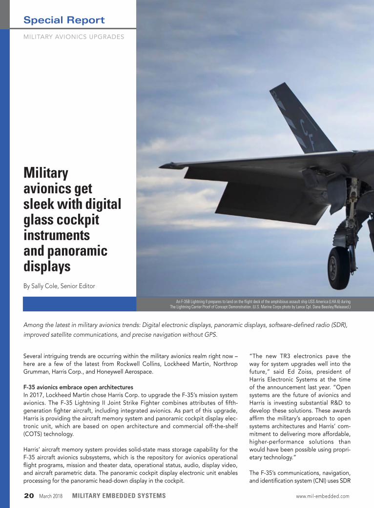
An F-35B Lightning II prepares to land on the flight deck of the amphibious assault ship USS America (LHA 6) during The Lightning Carrier Proof of Concept Demonstration. (U.S. Marine Corps photo by Lance Cpl. Dana Beesley/Released.)
Among the latest in military avionics trends: Digital electronic displays, panoramic displays, software-defined radio (SDR), improved satellite communications, and precise navigation without GPS.
Military avionics get sleek with digital glass cockpit instruments and panoramic displaysBy Sally Cole, Senior Editor
Several intriguing trends are occurring within the military avionics realm right now – here are a few of the latest from Rockwell Collins, Lockheed Martin, Northrop Grumman, Harris Corp., and Honeywell Aerospace.
F-35 avionics embrace open architecturesIn 2017, Lockheed Martin chose Harris Corp. to upgrade the F-35’s mission system avionics. The F-35 Lightning II Joint Strike Fighter combines attributes of fifth- generation fighter aircraft, including integrated avionics. As part of this upgrade, Harris is providing the aircraft memory system and panoramic cockpit display elec-tronic unit, which are based on open architecture and commercial off-the-shelf (COTS) technology.
Harris’ aircraft memory system provides solid-state mass storage capability for the F-35 aircraft avionics subsystems, which is the repository for avionics operational flight programs, mission and theater data, operational status, audio, display video, and aircraft parametric data. The panoramic cockpit display electronic unit enables processing for the panoramic head-down display in the cockpit.
MILITARY AVIONICS UPGRADES
Special Report
20 March 2018 MILITARY EMBEDDED SYSTEMS www.mil-embedded.com
technology from Northrop Grumman, which involves reconfigurable radio frequency (RF) hardware and computer processors to run software that pro-duces a desired waveform. By sharing common power, RF hardware, and com-puter processors, the avionics system becomes “integrated” CNI, according to the company.
Northrop Grumman’s fully integrated, simultaneous CNI avionics suite in- cludes advanced capabilities such as ultra-high-frequency/very-high- frequency transmit and receive, iden-tification friend or foe transponder, Link 16 connectivity, joint precision and approach landing system, wireless communications, and a cutting-edge multifunction advanced data link for low-observable or stealthy platforms.
Black Hawk cockpits and communicationMany other avionics systems are also undergoing digital upgrades. Northrop Grumman engineers have developed sleek digital helicopter cockpit and integrated avionics solutions for the U.S. Army’s UH-60V Black Hawk, replacing analog gauges with digital electronic instrument displays.
This particular system’s architecture is designed so that it can be applied to many platforms and sustained through a single software package.
Improving satellite communicationsHoneywell Aerospace is bringing upgraded satellite communications – in the form of access to real-time Internet, video, and voice and texting capabilities – to Black Hawk helicopters.
As part of this effort, Honeywell is upgrading the Federal Aviation Administration supplemental type certificate for the Aspire 200 Satellite Communications System for commercial Sikorsky UH-60 and S70 Black Hawk helicopters.
This upgrade includes a high-gain antenna, Honeywell’s latest Wi-Fi router, and the Scotty Communication Platform, which compiles and compresses large data files and high-definition video quickly and at a competitive rate. It’s designed to enable
www.mil-embedded.com MILITARY EMBEDDED SYSTEMS March 2018 21
communication in real-time video and, according to Honeywell, is the only broadband solution that mitigates the impacts of rotor blades on the satel-lite signal to ensure connectivity almost anywhere.
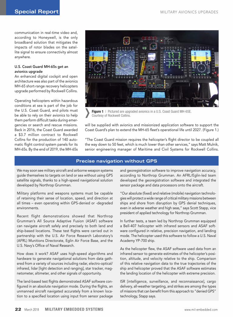
U.S. Coast Guard MH-65s get an avionics upgradeAn enhanced digital cockpit and open architecture was also part of the avionics MH-65 short-range recovery helicopters upgrade performed by Rockwell Collins.
Operating helicopters within hazardous conditions at sea is part of the job for the U.S. Coast Guard, and pilots must be able to rely on their avionics to help them perform difficult tasks during emer-gencies or search and rescue missions. Back in 2016, the Coast Guard awarded a $3.7 million contract to Rockwell Collins for the production of 140 auto-matic flight control system panels for its MH-65s. By the end of 2019, the MH-65s
will be supplied with avionics and missionized application software to support the Coast Guard’s plan to extend the MH-65 fleet’s operational life until 2027. (Figure 1.)
“The Coast Guard mission requires the helicopter’s flight director to be coupled all the way down to 50 feet, which is much lower than other services,” says Matt Mulnik, senior engineering manager of Maritime and Civil Systems for Rockwell Collins.
Figure 1 | Pictured are upgraded avionics in a U.S. Coast Guard MH-65E. Courtesy of Rockwell Collins.›
Special Report MILITARY AVIONICS UPGRADES
22 March 2018 MILITARY EMBEDDED SYSTEMS www.mil-embedded.com
Precise navigation without GPS
We may soon see military aircraft and airborne weapon systems guide themselves to targets on land or sea without using GPS satellite signals, thanks to a high-speed navigational solution developed by Northrop Grumman.
Military platforms and weapons systems must be capable of retaining their sense of location, speed, and direction at all times – even operating within GPS-denied or -degraded environments.
Recent flight demonstrations showed that Northrop Grumman’s All Source Adaptive Fusion (ASAF) software can navigate aircraft safely and precisely to both land and ship-based locations. These test flights were carried out in partnership with the U.S. Air Force Research Laboratory’s (AFRL) Munitions Directorate, Eglin Air Force Base, and the U.S. Navy’s Office of Naval Research.
How does it work? ASAF uses high-speed algorithms and hardware to generate navigational solutions from data gath-ered from a variety of sources including radar, electro-optical/infrared, lidar [light detection and ranging], star tracker, mag-netometer, altimeter, and other signals of opportunity.
The land-based test flights demonstrated ASAF software con-figured in an absolute navigation mode. During the flights, an unmanned aircraft navigated accurately from a known loca-tion to a specified location using input from sensor package
and georegistration software to improve navigation accuracy, according to Northrop Grumman. An AFRL/Eglin-led team developed the georegistration software and integrated the sensor package and data processors onto the aircraft.
“Our absolute (fixed) and relative (mobile) navigation technolo-gies will protect a wide range of critical military missions between ships and shore from disruption by GPS denial techniques, even in adverse weather and high seas,” says Scott Stapp, vice president of applied technology for Northrop Grumman.
In further tests, a team led by Northrop Grumman equipped a Bell-407 helicopter with infrared sensors and ASAF soft-ware configured in relative, precision navigation, and landing mode. The helicopter used this software to follow a U.S. Naval Academy YP-700 ship.
As the helicopter flew, the ASAF software used data from an infrared sensor to generate estimates of the helicopter’s posi-tion, altitude, and velocity relative to the ship. Comparison of this relative navigation data to the true trajectories of the ship and helicopter proved that the ASAF software estimates the landing location of the helicopter with extreme precision.
ISR [intelligence, surveillance, and reconnaissance], cargo delivery, all-weather targeting, and strikes are among the types of missions that can benefit from this approach to “denied GPS” technology, Stapp says.
“A pilot having that level of trust in their avionics in that situation is pretty extraordinary.”
What’s being upgraded in terms of dis-plays? One major new feature is all-glass, large-format digital displays to improve video and imaging options, according to Rockwell Collins, so that crews can view multiple video sources from both outside and inside the aircraft.
In other display upgrades, pilots will now be able to observe activity in the back of the helicopter, thanks to video from hoist and cabin cameras. Moreover, the external imaging from infrared radar and electro-optical sensors can also be displayed to allow pilots to save images and video to a mission data recorder for immediate review or to save for down-loading later.
These improved displays give pilots “increased situational awareness and a reduced workload, which can make a huge difference in challenging situations when every second counts,” says Heather Robertson, senior director of rotary wing solutions for Rockwell Collins.
As far as architecture, the system is designed with the latest open archi-tecture to enable the reuse of applica-tions developed on other programs and hosting them within this updated avionics system. This open design can run third-party applications, which maxi-mize pilots’ capabilities to reduce costs to upgrade the system.
The upgrade further includes Rockwell Collins’ integrated civil and military flight-management system, which the company says meets the requirements for area navigation and provides the special mission capability that the Coast Guard needs. It also satisfies aviation mandates to allow the aircraft to fly within civil airspace.
Search and rescue capabilities are also getting a boost: They’re receiving a full integration of Rockwell Collins’ DF-500 direction finder into the new flight-management system and display. This
upgrade is important because the DF-500’s receiver can now continuously scan for emergency beacons over a large frequency range to pinpoint the exact location of any detected beacon on the digital display. The pilot can then set the system to fly directly to that position, fly a search pattern if needed, and also view the point or the flight plan on a digital map, weather display, or terrain map.
Rockwell Collins “worked very closely with the Coast Guard to develop these new capabilities that will improve safety and effectiveness in future missions,” says Dhiraj Raghwani, programs manager of Maritime and Civil Systems for Rockwell Collins.
Other upgrade enhancements include installation of digital GPS and inertial naviga-tion, digital weather radar systems, and digital glass cockpit instruments. MES
www.mil-embedded.com MILITARY EMBEDDED SYSTEMS March 2018 23
Scalable, Multi-Protocol ConnectivityCompact Avionics Interface Computer (C-AIC)
Stay ConneCted
. : 990. ?0/
your solution provider for. . .ConneCtivity | Power | Control
D a t a D e v i c e c o r p o r a t i o n
To learn more, visit www.ddc-web.com/C-AIC/MES
54years of service
Applications Include:• Remote Access Mode – Embedded Tester/Simulator
- Simulate / analyze sensors from application running on remote computer
• Protocol Conversion Mode – Data Concentrator - Analyze, convert & consolidate multiple I/O types into a single port
• Embedded Solutions Mode – Mission Computer - Mission application runs on the C-AIC - Interface with platform sensors & terminals - Data Bus Protocol Conversion
Multi-Protocol Flexibility• Ethernet, MIL-STD-1553, ARINC 429/717, CANbus 2.0/ARINC 825, RS-232/422/485, Avionics/Digital Discrete I/O, Video, WiFi, GPS, Power Control, Motor Control, and Motion Feedback• 3 modes (Remote Access, Protocol Conversion, and Standalone) • Expandable: (2) Mini-PCIe sites and (1) I/O Expansion Module
SWaP-C Optimized System• Rugged Deployable Compact Enclosure• High Computing Performance, with Low Power Consumption
• MIL-STD-810G Shock, Vibration, and Immersion / MIL-STD-461F EMI
National Harbor, Maryland | April 9-11, 2018E-mail: [email protected]
Meet us at...Booth# 1749
For this example, we will calculate a numerical approximation of pi, but we need not discuss the details of the algorithm here. One of the benefits of using a source code profiler is the ability to grasp a deep understanding of the application’s perfor-mance, which can lead to performance improvements without requiring a deep understanding of the underlying mathematics. For any code optimization effort, it is critical to measure per-formance and code correctness at each step of optimization. It is useless to have very fast code that yields the wrong answer. By using a mature, industry-proven tool that includes both a HPC debugger and source code profiler, this effort is greatly simplified. Let’s start using the source code profiler to study our single thread implementation. From our run summary, we see that the program executed in 30.6 seconds, and from the main tread activity chart, we see that 100 percent of the time was spent in the single thread compute. (Figure 1.)
In the profiler, chart lines representing the percentage of time spent on each line of code is displayed next to the line. Therefore, from the data we can visually see that the bulk of time expended in our application is inside the “for” loop on line 68. (Figure 2.)
This loop is an ideal candidate for OpenMP, an easy-to-use, directive-based API for parallel programming. A pragma-based system, OpenMP can greatly simplify the threading of numerical algorithms by providing an abstraction to hide the complexity of creating threads, killing threads, and managing work synchroni-zation. (More information is available at www.openmp.org.)
Next, we add a pragma to parallelize the “for” loop on line 68. (Figure 3.) So, what is the pragma directing the compiler to
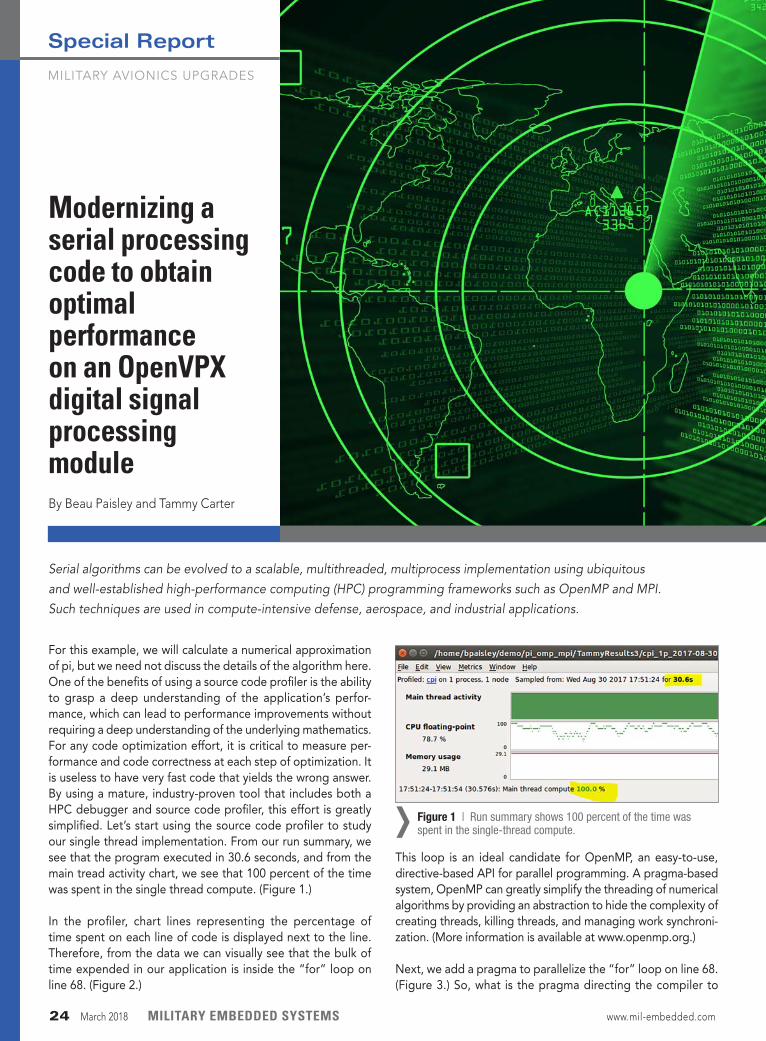
Modernizing a serial processing code to obtain optimal performance on an OpenVPX digital signal processing moduleBy Beau Paisley and Tammy Carter
Serial algorithms can be evolved to a scalable, multithreaded, multiprocess implementation using ubiquitous and well-established high-performance computing (HPC) programming frameworks such as OpenMP and MPI. Such techniques are used in compute-intensive defense, aerospace, and industrial applications.
Figure 1 | Run summary shows 100 percent of the time was spent in the single-thread compute.›
MILITARY AVIONICS UPGRADES
Special Report
24 March 2018 MILITARY EMBEDDED SYSTEMS www.mil-embedded.com
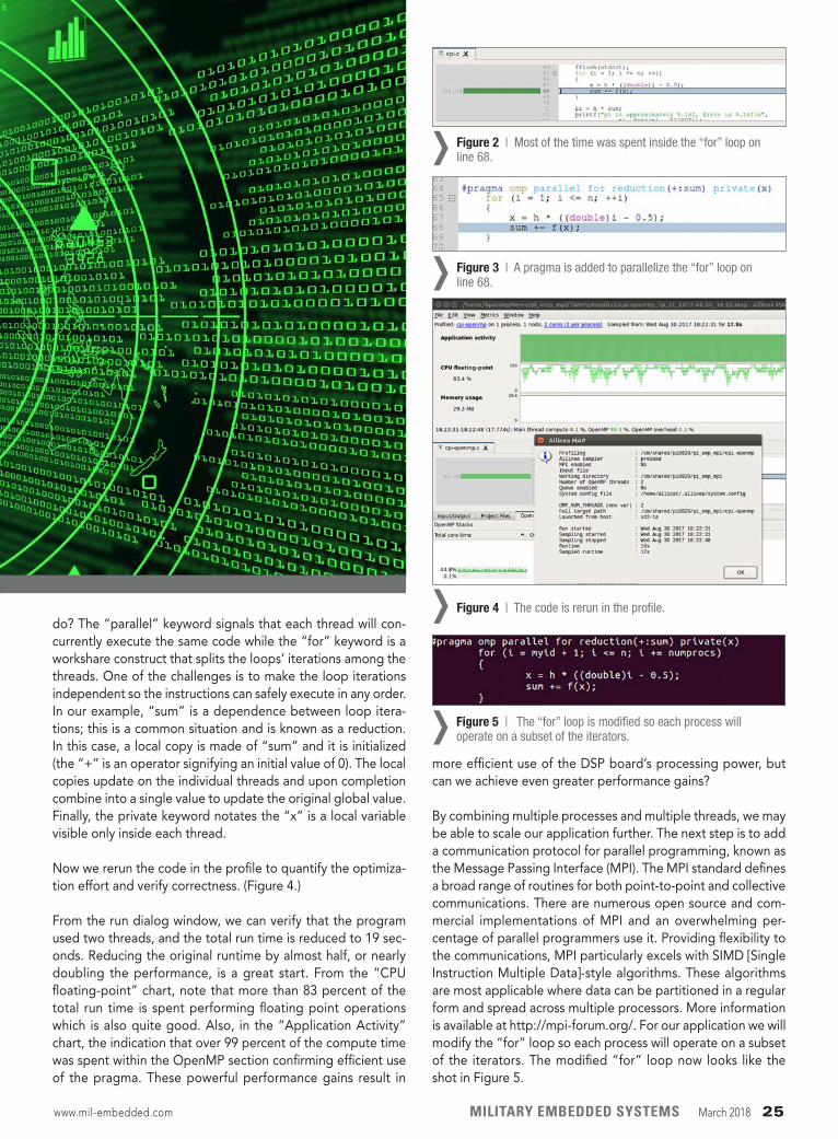
do? The “parallel” keyword signals that each thread will con-currently execute the same code while the “for” keyword is a workshare construct that splits the loops’ iterations among the threads. One of the challenges is to make the loop iterations independent so the instructions can safely execute in any order. In our example, “sum” is a dependence between loop itera-tions; this is a common situation and is known as a reduction. In this case, a local copy is made of “sum” and it is initialized (the “+” is an operator signifying an initial value of 0). The local copies update on the individual threads and upon completion combine into a single value to update the original global value. Finally, the private keyword notates the “x” is a local variable visible only inside each thread.
Now we rerun the code in the profile to quantify the optimiza-tion effort and verify correctness. (Figure 4.)
From the run dialog window, we can verify that the program used two threads, and the total run time is reduced to 19 sec-onds. Reducing the original runtime by almost half, or nearly doubling the performance, is a great start. From the “CPU floating-point” chart, note that more than 83 percent of the total run time is spent performing floating point operations which is also quite good. Also, in the “Application Activity” chart, the indication that over 99 percent of the compute time was spent within the OpenMP section confirming efficient use of the pragma. These powerful performance gains result in
more efficient use of the DSP board’s processing power, but can we achieve even greater performance gains?
By combining multiple processes and multiple threads, we may be able to scale our application further. The next step is to add a communication protocol for parallel programming, known as the Message Passing Interface (MPI). The MPI standard defines a broad range of routines for both point-to-point and collective communications. There are numerous open source and com-mercial implementations of MPI and an overwhelming per-centage of parallel programmers use it. Providing flexibility to the communications, MPI particularly excels with SIMD [Single Instruction Multiple Data]-style algorithms. These algorithms are most applicable where data can be partitioned in a regular form and spread across multiple processors. More information is available at http://mpi-forum.org/. For our application we will modify the “for” loop so each process will operate on a subset of the iterators. The modified “for” loop now looks like the shot in Figure 5.
Figure 2 | Most of the time was spent inside the “for” loop on line 68.›
Figure 3 | A pragma is added to parallelize the “for” loop on line 68.›
Figure 4 | The code is rerun in the profile.›
Figure 5 | The “for” loop is modified so each process will operate on a subset of the iterators.›
www.mil-embedded.com MILITARY EMBEDDED SYSTEMS March 2018 25
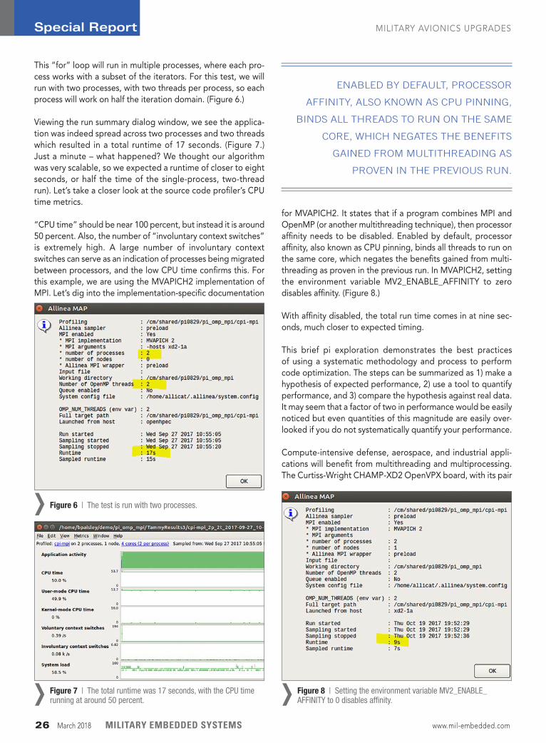
This “for” loop will run in multiple processes, where each pro-cess works with a subset of the iterators. For this test, we will run with two processes, with two threads per process, so each process will work on half the iteration domain. (Figure 6.)
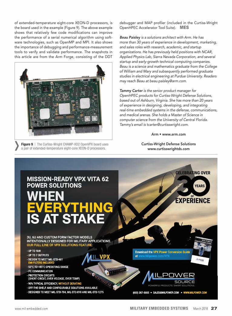
Viewing the run summary dialog window, we see the applica-tion was indeed spread across two processes and two threads which resulted in a total runtime of 17 seconds. (Figure 7.) Just a minute – what happened? We thought our algorithm was very scalable, so we expected a runtime of closer to eight seconds, or half the time of the single-process, two-thread run). Let’s take a closer look at the source code profiler’s CPU time metrics.
“CPU time” should be near 100 percent, but instead it is around 50 percent. Also, the number of “involuntary context switches” is extremely high. A large number of involuntary context switches can serve as an indication of processes being migrated between processors, and the low CPU time confirms this. For this example, we are using the MVAPICH2 implementation of MPI. Let’s dig into the implementation-specific documentation
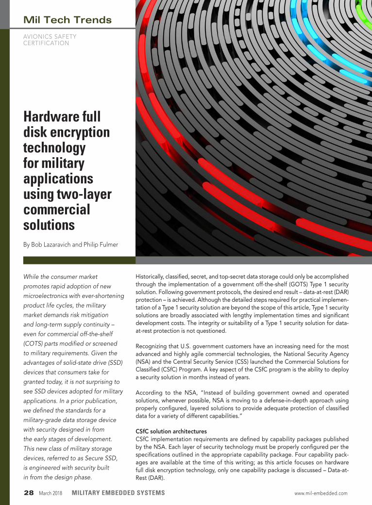
for MVAPICH2. It states that if a program combines MPI and OpenMP (or another multithreading technique), then processor affinity needs to be disabled. Enabled by default, processor affinity, also known as CPU pinning, binds all threads to run on the same core, which negates the benefits gained from multi-threading as proven in the previous run. In MVAPICH2, setting the environment variable MV2_ENABLE_AFFINITY to zero disables affinity. (Figure 8.)
With affinity disabled, the total run time comes in at nine sec-onds, much closer to expected timing.
This brief pi exploration demonstrates the best practices of using a systematic methodology and process to perform code optimization. The steps can be summarized as 1) make a hypothesis of expected performance, 2) use a tool to quantify performance, and 3) compare the hypothesis against real data. It may seem that a factor of two in performance would be easily noticed but even quantities of this magnitude are easily over-looked if you do not systematically quantify your performance.
Compute-intensive defense, aerospace, and industrial appli-cations will benefit from multithreading and multiprocessing. The Curtiss-Wright CHAMP-XD2 OpenVPX board, with its pair
Figure 7 | The total runtime was 17 seconds, with the CPU time running at around 50 percent.› Figure 8 | Setting the environment variable MV2_ENABLE_
AFFINITY to 0 disables affinity.›
Figure 6 | The test is run with two processes.›
Special Report MILITARY AVIONICS UPGRADES
26 March 2018 MILITARY EMBEDDED SYSTEMS www.mil-embedded.com
ENABLED BY DEFAULT, PROCESSOR
AFFINITY, ALSO KNOWN AS CPU PINNING,
BINDS ALL THREADS TO RUN ON THE SAME
CORE, WHICH NEGATES THE BENEFITS
GAINED FROM MULTI THREADING AS
PROVEN IN THE PREVIOUS RUN.
of extended-temperature eight-core XEON-D processors, is the board used in the example (Figure 9). The above example shows that relatively few code modifications can improve the performance of a serial numerical algorithm using soft-ware technologies, such as OpenMP and MPI. It also shows the importance of debugging and performance-measurement tools to verify and validate performance. The snapshots in this article are from the Arm Forge, consisting of the DDT
debugger and MAP profiler (included in the Curtiss-Wright OpenHPEC Accelerator Tool Suite). MES
Beau Paisley is a solutions architect with Arm. He has more than 30 years of experience in development, marketing, and sales roles with research, academic, and startup organizations. He has previously held positions with NCAR, Applied Physics Lab, Sierra Nevada Corporation, and several startup and early-growth technical computing companies. Beau is a science and mathematics graduate from the College of William and Mary and subsequently performed graduate studies in electrical engineering at Purdue University. Readers may reach Beau at [email protected].
Tammy Carter is the senior product manager for OpenHPEC products for Curtiss-Wright Defense Solutions, based out of Ashburn, Virginia. She has more than 20 years of experience in designing, developing, and integrating real-time embedded systems in the defense, communications, and medical arenas. She holds a Master of Science in computer science from the University of Central Florida. Tammy’s email is [email protected].
Arm • www.arm.com
Curtiss-Wright Defense Solutions www.curtisswrightds.com
- UP TO 1kW- UP TO 7 OUTPUTS- DESIGN TO MEET MIL-STD-461 EMI FILTERS INCLUDED- 55°C TO +85°C OPERATIING RANGE- I2C COMMUNICATION- PR- PROTECTION CIRCUITS (SHORT CIRCUT, OVER VOLTAGE, OVER TEMP)
- 90% TYPICAL EFFICIENCY, WITHOUT DERATING- OFF-THE-SHELF AND CONFIGURABLE SOLUTIONS AVAILABLE- DESIGNED TO MEET MIL-STD-704, MIL-STD-810 AND MIL-STD-1275
MISSION-READY VPX VITA 62 POWER SOLUTIONS
WHEN EVERYTHING IS AT STAKE3U, 6U AND CUSTOM FORM FACTOR MODELS INTENTIONALLY DESIGNED FOR MILITARY APPLICATIONS. OUR FULL LINE OF VPX SOLUTIONS FEATURE:
Download the VPX Power Conversion Guideat www.Milpower.com/VPX
(603) 267-8865 • [email protected] • WWW.MILPOWER.COM
Figure 9 | The Curtiss-Wright CHAMP-XD2 OpenVPX board uses a pair of extended-temperature eight-core XEON-D processors.›
www.mil-embedded.com MILITARY EMBEDDED SYSTEMS March 2018 27
While the consumer market promotes rapid adoption of new microelectronics with ever-shortening product life cycles, the military market demands risk mitigation and long-term supply continuity – even for commercial off-the-shelf (COTS) parts modified or screened to military requirements. Given the advantages of solid-state drive (SSD) devices that consumers take for granted today, it is not surprising to see SSD devices adopted for military applications. In a prior publication, we defined the standards for a military-grade data storage device with security designed in from the early stages of development. This new class of military storage devices, referred to as Secure SSD, is engineered with security built in from the design phase.
Historically, classified, secret, and top-secret data storage could only be accomplished through the implementation of a government off-the-shelf (GOTS) Type 1 security solution. Following government protocols, the desired end result – data-at-rest (DAR) protection – is achieved. Although the detailed steps required for practical implemen-tation of a Type 1 security solution are beyond the scope of this article, Type 1 security solutions are broadly associated with lengthy implementation times and significant development costs. The integrity or suitability of a Type 1 security solution for data-at-rest protection is not questioned.
Recognizing that U.S. government customers have an increasing need for the most advanced and highly agile commercial technologies, the National Security Agency (NSA) and the Central Security Service (CSS) launched the Commercial Solutions for Classified (CSfC) Program. A key aspect of the CSfC program is the ability to deploy a security solution in months instead of years.
According to the NSA, “Instead of building government owned and operated solutions, whenever possible, NSA is moving to a defense-in-depth approach using properly configured, layered solutions to provide adequate protection of classified data for a variety of different capabilities.”
CSfC solution architecturesCSfC implementation requirements are defined by capability packages published by the NSA. Each layer of security technology must be properly configured per the specifications outlined in the appropriate capability package. Four capability pack-ages are available at the time of this writing; as this article focuses on hardware full disk encryption technology, only one capability package is discussed – Data-at- Rest (DAR).
Mil Tech Trends
AVIONICS SAFETY CERTIFICATION
Hardware full disk encryption technology for military applications using two-layer commercial solutionsBy Bob Lazaravich and Philip Fulmer
28 March 2018 MILITARY EMBEDDED SYSTEMS www.mil-embedded.com
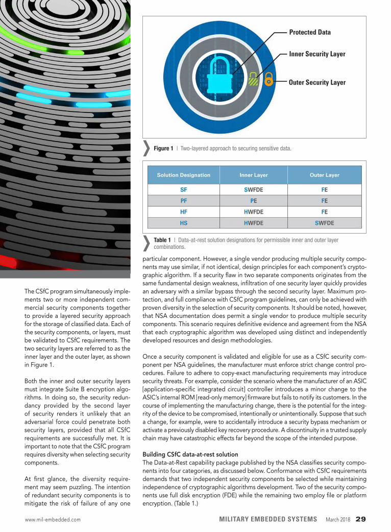
The CSfC program simultaneously imple-ments two or more independent com-mercial security components together to provide a layered security approach for the storage of classified data. Each of the security components, or layers, must be validated to CSfC requirements. The two security layers are referred to as the inner layer and the outer layer, as shown in Figure 1.
Both the inner and outer security layers must integrate Suite B encryption algo-rithms. In doing so, the security redun-dancy provided by the second layer of security renders it unlikely that an adversarial force could penetrate both security layers, provided that all CSfC requirements are successfully met. It is important to note that the CSfC program requires diversity when selecting security components.
At first glance, the diversity require-ment may seem puzzling. The intention of redundant security components is to mitigate the risk of failure of any one
particular component. However, a single vendor producing multiple security compo-nents may use similar, if not identical, design principles for each component’s crypto-graphic algorithm. If a security flaw in two separate components originates from the same fundamental design weakness, infiltration of one security layer quickly provides an adversary with a similar bypass through the second security layer. Maximum pro-tection, and full compliance with CSfC program guidelines, can only be achieved with proven diversity in the selection of security components. It should be noted, however, that NSA documentation does permit a single vendor to produce multiple security components. This scenario requires definitive evidence and agreement from the NSA that each cryptographic algorithm was developed using distinct and independently developed resources and design methodologies.
Once a security component is validated and eligible for use as a CSfC security com-ponent per NSA guidelines, the manufacturer must enforce strict change control pro-cedures. Failure to adhere to copy-exact manufacturing requirements may introduce security threats. For example, consider the scenario where the manufacturer of an ASIC [application-specific integrated circuit] controller introduces a minor change to the ASIC’s internal ROM [read-only memory] firmware but fails to notify its customers. In the course of implementing the manufacturing change, there is the potential for the integ-rity of the device to be compromised, intentionally or unintentionally. Suppose that such a change, for example, were to accidentally introduce a security bypass mechanism or activate a previously disabled key recovery procedure. A discontinuity in a trusted supply chain may have catastrophic effects far beyond the scope of the intended purpose.
Building CSfC data-at-rest solution The Data-at-Rest capability package published by the NSA classifies security compo-nents into four categories, as discussed below. Conformance with CSfC requirements demands that two independent security components be selected while maintaining independence of cryptographic algorithms development. Two of the security compo-nents use full disk encryption (FDE) while the remaining two employ file or platform encryption. (Table 1.)
Figure 1 | Two-layered approach to securing sensitive data.›
Table 1 | Data-at-rest solution designations for permissible inner and outer layer combinations.›
www.mil-embedded.com MILITARY EMBEDDED SYSTEMS March 2018 29
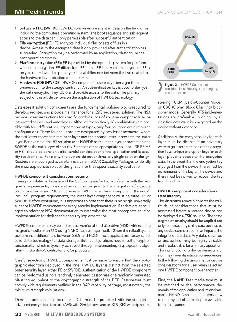
› Software FDE (SWFDE): SWFDE components encrypt all data on the hard drive, including the computer’s operating system. The boot sequence and subsequent access to the data can is only permissible after successful authentication.
› File encryption (FE): FE encrypts individual files or sets of files in a device. Access to the encrypted data is only provided after authentication has succeeded. Encryption may be performed by an application, platform, or the host operating system.
› Platform encryption (PE): PE is provided by the operating system for platform-wide data encryption. PE differs from FE in that PE is only an inner layer and FE is only an outer layer. The primary technical difference between the two related to the hardware key protection requirements.
› Hardware FDE (HWFDE): HWFDE components use encryption algorithms embedded into the storage controller. An authentication key is used to decrypt the data encryption key (DEK) and provide access to the data. The primary subject of this article centers on the application of HWFDE technology.
Data-at-rest solution components are the fundamental building blocks required to develop, register, and provide maintenance for a CSfC registered solution. The NSA provides clear instructions for specific combinations of solution components to be integrated as inner and outer layers. Although theoretically 16 combinations are pos-sible with four different security component types, only four solutions are authorized configurations. These four solutions are designated by two-letter acronyms, where the first letter represents the inner layer and the second letter represents the outer layer. For example, the HS solution uses HWFDE as the inner layer of protection and SWFDE as the outer layer of security. Selection of the appropriate solution – SF, PF, HF, or HS – should be done only after careful consideration of the application and its secu-rity requirements. For clarity, the authors do not endorse any single solution design. Readers are encouraged to carefully evaluate the DAR Capability Packages to identify the most appropriate solution designation for their specific security application.
HWFDE component considerations: securityHaving completed a discussion of the CSfC program for those unfamiliar with the pro-gram’s requirements, consideration can now be given to the integration of a Secure SSD into a two-layer CSfC solution as a HWFDE inner layer component. (Figure 2.) Per CSfC program requirements, the outer layer component must be either FE or SWFDE. Before continuing, it is important to note that there is no single universally superior HWFDE component for every security implementation. Readers are encour-aged to reference NSA documentation to determine the most appropriate solution implementation for their specific security implementation.
HWFDE components may be either a conventional hard disk drive (HDD) with rotating magnetic media or an SSD using NAND flash storage media. Given the reliability and performance differentials between SSDs and HDDs, most applications today select solid-state technology for data storage. Both configurations require self-encryption functionality, which is typically achieved through implementing cryptographic algo-rithms in the drive’s controller and/or processor.
Careful selection of HWFDE components must be made to ensure that the crypto-graphic algorithm deployed in the inner HWFDE layer is distinct from the selected outer security layer, either FE or SWFDE. Authentication of the HWFDE component can be performed using a randomly generated passphrase or a randomly generated bit-string equivalent to the cryptographic strength of the DEK. Passphrases must comply with requirements outlined in the DAR capability package, most notably the minimum strength calculations.
There are additional considerations. Data must be protected with the strength of advanced encryption standard (AES) with 256-bit keys and an XTS (XEX with ciphertext
stealing), GCM (Galois/Counter Mode), or CBC (Cipher Block Chaining) block cipher mode. Generally, XTS implemen-tations are preferable. In doing so, all classified data must be encrypted on the device without exception.
Additionally, the encryption key for each layer must be distinct. If an adversary were to gain access to one of the encryp-tion keys, unique encryption keys for each layer prevents access to the encrypted data. In the event that the encryption key is purged from the device, there must be no remnants of the key on the device and there must be no way to recover the key from the drive.
HWFDE component considerations: Data integrityThe discussion above highlights the mul-titude of considerations that must be addressed before a storage device can be deployed in a CSfC solution. The same degree of scrutiny should be applied not only to the security of the data but also to any device consideration that impacts the integrity of the data. Any data, classified or unclassified, may be highly valuable and irreplaceable for a military operation. The malfunction of a device during a mis-sion may have disastrous consequences. In the following discussion, let us discuss considerations for a user when selecting one HWFDE component over another.
First, the NAND flash media type must be matched to the performance de- mands of the application and its environ-ment. NAND flash manufacturers now offer a myriad of technologies available to the consumer:
Figure 2 | HWFDE Component considerations: Security, data integrity, and form factor.
›
Mil Tech Trends AVIONICS SAFETY CERTIFICATION
30 March 2018 MILITARY EMBEDDED SYSTEMS www.mil-embedded.com
› Single-level cell (SLC) NAND flash stores only one bit per cell yet offers 10 times higher data endurance than the next best alternative media type. It also has the most robust operating tem- perature range, -40 °C to +85 °C. SLC technology is the media of choice for applications storing data that cannot be replaced in the event of an SSD failure.
› Multi-level cell (MLC) NAND flash, in contrast, stores two bits per cell, thereby offering a larger data storage capacity at a significantly reduced cost. However, this increased capacity comes at the expense of reduced read/write endurance compared to SLC NAND and shorter data retention.
› Triple-level cell (TLC) technology stores three bits per cell, thereby further reducing cost, with additional penalties beyond MLC technology in terms of data endurance and operational lifetime.
› 3-D NAND technology vertically stacks storage cells to surmount the scaling limitations of conventional planar (SLC, MLC, TLC) technologies. At the time of this writing, 3-D NAND memories are available only with operating temperatures of 0 °C to +70 °C. Although 3-D NAND technology does allow further scaling, the vertical integration does present new reliability issues.
With a myriad of NAND technologies, selecting the appropriate SSD for a given application is not a trivial exer-cise. As a rule of thumb, selecting a SSD based on SLC technology is clearly the safest approach when data integrity is critical and/or operating temperatures are below 0 °C or exceed +70 °C. Under commercial operating temperatures where the SSD can be readily replaced as a preventative maintenance opera-tion, MLC technology offers higher storage capacities suitable for high-volume data record recording applica-tions where the data has limited lifetime value. At the time of this writing, TLC and 3-D NAND technologies have not yet reached a maturity level where the authors can recommend their consider-ation for military applications.
Those selecting a HWFDE component are encouraged to inquire with the manufac-turer about performance throttling algorithms designed to extend the useful lifetime of a device. Normally these algorithms are activated under heavy-duty-cycle opera-tion or high-temperature operation, but are not advertised by the SSD manufacturer. Extended operational lifetime sounds like a benefit to the user; however, extended operational lifetime comes at the expense of non-deterministic and reduced read and write speeds. Although potentially acceptable for commercial applications, many military applications demand continuous high-speed data capture at extended temperatures for a successful mission.
Assuming the NAND flash media and controller architecture of the SSD have been addressed, one additional question remains: In the event of a sudden power loss, what happens to the cells that are being read and/or written? A sudden disruption in power may lead to the corruption or loss of data if the device has no mechanism to ensure an orderly and deterministic shutdown procedure. Batteries, supercapacitors, and other means of data preservation can be integrated into the device’s architecture. Users are cautioned when selecting any solution deploying batteries or supercapacitors, as their effectiveness is limited in environments requiring low and high temperature operation.
HWFDE component considerations: Form factorThe industry standard 2.5-inch form factor is the de facto configuration. However, not all 2.5-inch SSD packages are created equal. The shock and vibration conditions, both expected and unexpected during deployment, must be evaluated. The physical package/enclosure of the SSD must be structurally validated to survive all shock and vibration conditions possible in the given application. Further consideration must be given to the integrity of the mechanically connecting interface between the SSD and the host system. Ruggedized mechanically interlocking connectors minimize the pos-sibility of an accidental disconnect from the host system. Scenarios may arise where a user requires an alternate form factor, such as mSATA or XMC card.
Can the SSD manufacturer support the rapid development and qualification proce-dures to achieve eligibility for use as a CSfC solution component? Is the controller architecture portable and readily adapted to the new form factor? If the manufacturer has not even achieved third-party qualifications – such as FIPS 140-2 and Common Criteria – on one form factor, it is highly unlikely that the review and qualification process needed for the new form factor can be completed quickly.
A properly configured and implemented two-layer security solution, per CSfC pro-gram guidelines, can be used to properly secure sensitive military data. For security implementations using hardware full-disk encryption technology, however, not all hard-ware solutions are created equal; careful consideration must be given to the use case scenario. In particular, the solution must remember that the hardware manufacturer’s choice of design parameters, which are not specified by the CSfC program, may have both short- and long-term consequences for the security implementation. MES
Bob Lazaravich is the Technical Director for the Secure Solid State Drive product line at Mercury Systems in Phoenix, Arizona. Bob frequently engages with customers to implement security features tailored to address application-specific requirements. Bob received his BSE and MSE degrees in Electrical Engineering from Arizona State University.
Philip Fulmer is the Director of Product Marketing for the Mercury Systems Advanced Microelectronics Solutions group in San Jose, California. Philip received his BS degree in Chemistry from the University of Scranton and MSE degree in Materials Science and Engineering from the University of Texas at Austin.
Mercury Systems • www.mrcy.com
www.mil-embedded.com MILITARY EMBEDDED SYSTEMS March 2018 31
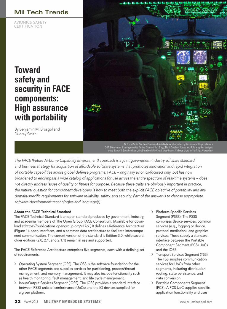
Mil Tech Trends
AVIONICS SAFETY CERTIFICATION
› Platform-Specific Services Segment (PSSS). The PSSS comprises device services, common services (e.g., logging or device protocol mediation), and graphics services. These supply a standard interface between the Portable Component Segment (PCS) UoCs and the IOSS.
› Transport Services Segment (TSS). The TSS supplies communication services for UoCs from other segments, including distribution, routing, state persistence, and data conversion.
› Portable Components Segment (PCS). A PCS UoC supplies specific application functionality and uses
About the FACE Technical StandardThe FACE Technical Standard is an open standard produced by government, industry, and academia members of The Open Group FACE Consortium. (Available for down-load at https://publications.opengroup.org/c17c/.) It defines a Reference Architecture (Figure 1), open interfaces, and a common data architecture to facilitate intercompo-nent communication. The current version of the standard is Edition 3.0, while several older editions (2.0, 2.1, and 2.1.1) remain in use and supported.
The FACE Reference Architecture comprises five segments, each with a defining set of requirements:
› Operating System Segment (OSS). The OSS is the software foundation for the other FACE segments and supplies services for partitioning, process/thread management, and memory management. It may also include functionality such as health monitoring, fault management, and life cycle management.
› Input/Output Services Segment (IOSS). The IOSS provides a standard interface between PSSS units of conformance (UoCs) and the IO devices supplied for a given platform.
The FACE [Future Airborne Capability Environment] approach is a joint government-industry software standard and business strategy for acquisition of affordable software systems that promotes innovation and rapid integration of portable capabilities across global defense programs. FACE – originally avionics-focused only, but has now broadened to encompass a wide catalog of applications for use across the entire spectrum of real-time systems – does not directly address issues of quality or fitness for purpose. Because these traits are obviously important in practice, the natural question for component developers is how to meet both the explicit FACE objective of portability and any domain-specific requirements for software reliability, safety, and security. Part of the answer is to choose appropriate software-development technologies and language(s).
Toward safety and security in FACE components: High assurance with portabilityBy Benjamin M. Brosgol and Dudrey Smith
Air Force Capts. Nikolaus Krause and Josh Bolla are illuminated by the instrument lights aboard a C-17 Globemaster III during exercise Panther Storm at Fort Bragg, North Carolina. Krause and Bolla are pilots assigned
to the 8th Airlift Squadron from Joint Base Lewis-McChord, Washington. Air Force photo by Staff Sgt. Andrew Lee.
32 March 2018 MILITARY EMBEDDED SYSTEMS www.mil-embedded.com
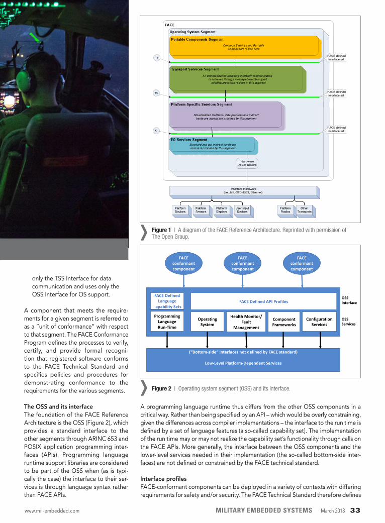
only the TSS Interface for data communication and uses only the OSS Interface for OS support.
A component that meets the require-ments for a given segment is referred to as a “unit of conformance” with respect to that segment. The FACE Conformance Program defines the processes to verify, certify, and provide formal recogni-tion that registered software conforms to the FACE Technical Standard and specifies policies and procedures for demonstrating conformance to the requirements for the various segments.
The OSS and its interfaceThe foundation of the FACE Reference Architecture is the OSS (Figure 2), which provides a standard interface to the other segments through ARINC 653 and POSIX application programming inter-faces (APIs). Programming language runtime support libraries are considered to be part of the OSS when (as is typi-cally the case) the interface to their ser-vices is through language syntax rather than FACE APIs.
A programming language runtime thus differs from the other OSS components in a critical way. Rather than being specified by an API – which would be overly constraining, given the differences across compiler implementations – the interface to the run time is defined by a set of language features (a so-called capability set). The implementation of the run time may or may not realize the capability set’s functionality through calls on the FACE APIs. More generally, the interface between the OSS components and the lower-level services needed in their implementation (the so-called bottom-side inter-faces) are not defined or constrained by the FACE technical standard.
Interface profilesFACE-conformant components can be deployed in a variety of contexts with differing requirements for safety and/or security. The FACE Technical Standard therefore defines
www.mil-embedded.com MILITARY EMBEDDED SYSTEMS March 2018 33
Figure 1 | A diagram of the FACE Reference Architecture. Reprinted with permission of The Open Group.›
Figure 2 | Operating system segment (OSS) and its interface.›
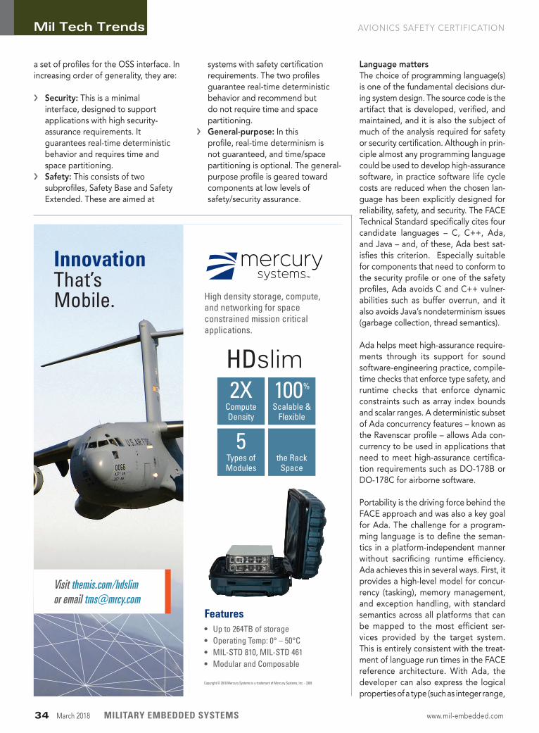
a set of profiles for the OSS interface. In increasing order of generality, they are:
› Security: This is a minimal interface, designed to support applications with high security-assurance requirements. It guarantees real-time deterministic behavior and requires time and space partitioning.
› Safety: This consists of two subprofiles, Safety Base and Safety Extended. These are aimed at
systems with safety certification requirements. The two profiles guarantee real-time deterministic behavior and recommend but do not require time and space partitioning.
› General-purpose: In this profile, real-time determinism is not guaranteed, and time/space partitioning is optional. The general-purpose profile is geared toward components at low levels of safety/security assurance.
Language mattersThe choice of programming language(s) is one of the fundamental decisions dur-ing system design. The source code is the artifact that is developed, verified, and maintained, and it is also the subject of much of the analysis required for safety or security certification. Although in prin-ciple almost any programming language could be used to develop high-assurance software, in practice software life cycle costs are reduced when the chosen lan-guage has been explicitly designed for reliability, safety, and security. The FACE Technical Standard specifically cites four candidate languages – C, C++, Ada, and Java – and, of these, Ada best sat-isfies this criterion. Especially suitable for components that need to conform to the security profile or one of the safety profiles, Ada avoids C and C++ vulner-abilities such as buffer overrun, and it also avoids Java’s nondeterminism issues (garbage collection, thread semantics).
Ada helps meet high-assurance require-ments through its support for sound software-engineering practice, compile-time checks that enforce type safety, and runtime checks that enforce dynamic constraints such as array index bounds and scalar ranges. A deterministic subset of Ada concurrency features – known as the Ravenscar profile – allows Ada con-currency to be used in applications that need to meet high-assurance certifica-tion requirements such as DO-178B or DO-178C for airborne software.
Portability is the driving force behind the FACE approach and was also a key goal for Ada. The challenge for a program-ming language is to define the seman-tics in a platform-independent manner without sacrificing runtime efficiency. Ada achieves this in several ways. First, it provides a high-level model for concur-rency (tasking), memory management, and exception handling, with standard semantics across all platforms that can be mapped to the most efficient ser-vices provided by the target system. This is entirely consistent with the treat-ment of language run times in the FACE reference architecture. With Ada, the developer can also express the logical properties of a type (such as integer range,
Mil Tech Trends AVIONICS SAFETY CERTIFICATION
34 March 2018 MILITARY EMBEDDED SYSTEMS www.mil-embedded.com
Copyright © 2018 Mercury Systems is a trademark of Mercury Systems, Inc. - 3389
Innovation That’sMobile.
Visit themis.com/hdslim or email [email protected]
Features• Up to 264TB of storage• Operating Temp: 0° – 50°C • MIL-STD 810, MIL-STD 461• Modular and Composable
High density storage, compute, and networking for space constrained mission critical applications.
HDslim100%
Scalable &Flexible
2XComputeDensity
5Types ofModules
½the Rack
Space
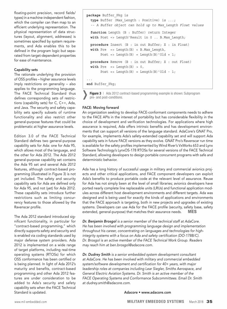
floating-point precision, record fields/types) in a machine-independent fashion, which the compiler can then map to an efficient underlying representation. The physical representation of data struc-tures (layout, alignment, addresses) is sometimes specified by system require-ments, and Ada enables this to be defined in the program logic but sepa-rated from target-dependent properties for ease of maintenance.
Capability setsThe rationale underlying the provision of OSS profiles – higher assurance levels imply restrictions on generality – also applies to the programming language. The FACE Technical Standard thus defines corresponding sets of restric-tions (capability sets) for C, C++, Ada, and Java. The security and safety capa-bility sets specify subsets of runtime functionality and also restrict other general-purpose features that could be problematic at higher assurance levels.
Edition 3.0 of the FACE Technical Standard defines two general-purpose capability sets for Ada: one for Ada 95, which allows most of the language, and the other for Ada 2012. The Ada 2012 general-purpose capability set contains the Ada 95 set and several Ada 2012 features, although contract-based pro-gramming (illustrated in Figure 3) is not yet included. The safety and security capability sets for Ada are defined only for Ada 95, and not (yet) for Ada 2012. These capability sets introduce further restrictions such as limiting concur-rency features to those allowed by the Ravenscar profile.
The Ada 2012 standard introduced sig-nificant functionality, in particular for “contract-based programming,” which directly supports safety and security and is enabled via coding standards used by major defense system providers. Ada 2012 is implemented on a wide range of target platforms, including real-time operating systems (RTOSs) for which OSS conformance has been certified or is being planned. In light of Ada 2012’s maturity and benefits, contract-based programming and other Ada 2012 fea- tures are under consideration to be added to Ada’s security and safety capability sets when the FACE Technical Standard is updated.
FACE: Moving forwardAn organization seeking to develop FACE-conformant components needs to adhere to the FACE APIs in the interest of portability but has considerable flexibility in the choice of development and verification technologies. For applications where high assurance is required, Ada offers intrinsic benefits and has development environ-ments that can support all versions of the language standard. AdaCore’s GNAT Pro, for example, implements Ada’s safety-extended capability set and will support Ada capability sets in future FACE versions as they evolve. GNAT Pro’s Ravenscar run time is available for the safety profiles implemented by Wind River’s VxWorks 653 and Lynx Software Technology’s LynxOS-178 RTOSs for several versions of the FACE Technical Standard, allowing developers to design portable concurrent programs with safe and deterministic behavior.
Ada has a long history of successful usage in military and commercial avionics proj-ects and other critical applications, and FACE component developers can exploit Ada’s benefits to produce portable code at the relevant level of assurance. Reuse for Ada has not simply been at the level of small libraries; avionics developers have ported nearly complete line replaceable units (LRUs) and functional application mod-ules across different host development environments and different targets. Ada was designed and is being used for exactly the kinds of applications and environments that the FACE approach is targeting, both in new projects and upgrades of existing systems. Developers can use Ada for the FACE profile (security, safety base, safety extended, general-purpose) that matches their assurance needs. MES
Dr. Benjamin Brosgol is a senior member of the technical staff at AdaCore. He has been involved with programming language design and implementation throughout his career, concentrating on languages and technologies for high-integrity systems with a focus on Ada and safety certification (DO-178B/C). Dr. Brosgol is an active member of the FACE Technical Work Group. Readers may reach him at [email protected].
Dr. Dudrey Smith is a senior embedded system development consultant at AdaCore. He has been involved with military and commercial embedded system/software development and certification for 40+ years, with major leadership roles at companies including Lear Siegler, Smiths Aerospace, and General Electric Aviation Systems. Dr. Smith is an active member of the FACE Operating Systems and Conformance Subcommittees. Email Dr. Smith at [email protected].
Adacore • www.adacore.com
www.mil-embedded.com MILITARY EMBEDDED SYSTEMS March 2018 35
Figure 3 | Ada 2012 contract-based programming example is shown: Subprogram pre- and post-conditions.›
package Buffer_Pkg is type Buffer (Max_Length : Positive) is ...; -- A Buffer object can hold up to Max_Length Float values
function Length (B : Buffer) return Integer with Post => Length’Result in 0 .. B.Max_Length;
procedure Insert (B : in out Buffer; X : in Float) with Pre => Length(B) < B.Max_Length, Post => Length(B) = Length(B)’Old + 1;
procedure Remove (B : in out Buffer; X : out Float) with Pre => Length(B) > 0, Post => Length(B) = Length(B)’Old - 1;
...
end Buffer_Pkg;

The constant push for increased bandwidth requirements mean that avionics engineers must continually design connectors that handle ever-higher data rates. As connector designs focus more squarely on data rates, all kinds of users are asking for the most cutting-edge technology – all within a small package.
Reduced military size and weight applications such as manned and unmanned aircraft are driving innovation among avionics connector suppliers who are already pushing the boundaries of speed, reliability, and signal integrity in their solutions.
“Military aircraft are rapidly evolving their internal electronics,” says Bob Stanton, director of technology at Omnetics Connector Corp. (Minneapolis, Minnesota). “High-speed digital chip technology has affected circuit interconnection elements. Circuits are digital and run at very high digital speeds that require lower voltages and demand lower current flow within the signals”
“Higher-speed protocols such as 100GBase-KR4 Ethernet and PCIe Gen 4 are being planned for new designs for faster processing,” says Mike Walmsley, global product manager, TE Connectivity (TE) Aerospace, Defense & Marine (Schaffhausen, Switzerland). “Advances in electronics packaging are driving smaller, lighter, multi-function systems and the interconnects need to support the higher pin counts within a small package. So speed and density are critical for connectors in new military avionics designs, while maintaining a robust connector design.”
Stanton notes that with high speeds, “the circuits can cause more electrical noise that affects crosstalk between signals and possibly generate EMI [electromagnetic inter-ference] noises that bother other circuits.”
These realities mean that signal integrity and reliability become huge factors when designing military aerospace systems. “Interconnect reliability under high vibration and temperature cycling is critical for military avionics,” Wamsley says. “We developed
Figure 1 | The MULTIGIG RT 3 connector can support data rates to 25 Gb/s while maintaining the VPX connector interface for backward compatibility. Photo courtesy of TE Connectivity.
›
connectors like MULTIGIG RT 2-R specifi-cally for these extreme environments and are proven across multiple platforms. The key trends we see moving forward are more bandwidth and smaller packaging.”
TE Connectivity collaborated with Curtiss-Wright Defense Solutions to launch the next version of the MULTIGIG RT-2R (Figure 1), Wamsley notes. “The
Industry Spotlight
AVIONICS CONNECTORS
The need for speed: Avionics connectors evolve to meet today’s bandwidth requirementsBy Mariana Iriarte, Technology Editor
36 March 2018 MILITARY EMBEDDED SYSTEMS www.mil-embedded.com
Avionics specialists prepare the Global Hawk for a runway taxi test. U.S. Air Force photo/Stacey Knott.
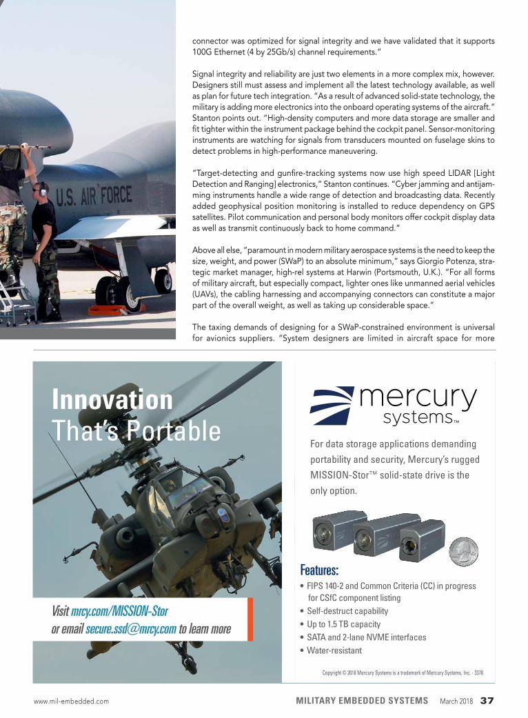
Visit mrcy.com/MISSION-Storor email [email protected] to learn more
Copyright © 2018 Mercury Systems is a trademark of Mercury Systems, Inc. - 3378
InnovationThat’s Portable
For data storage applications demanding
portability and security, Mercury’s rugged
MISSION-Stor™ solid-state drive is the
only option.
Features:• FIPS 140-2 and Common Criteria (CC) in progress
for CSfC component listing• Self-destruct capability• Up to 1.5 TB capacity• SATA and 2-lane NVME interfaces• Water-resistant
connector was optimized for signal integrity and we have validated that it supports 100G Ethernet (4 by 25Gb/s) channel requirements.”
Signal integrity and reliability are just two elements in a more complex mix, however. Designers still must assess and implement all the latest technology available, as well as plan for future tech integration. “As a result of advanced solid-state technology, the military is adding more electronics into the onboard operating systems of the aircraft.” Stanton points out. “High-density computers and more data storage are smaller and fit tighter within the instrument package behind the cockpit panel. Sensor-monitoring instruments are watching for signals from transducers mounted on fuselage skins to detect problems in high-performance maneuvering.
“Target-detecting and gunfire-tracking systems now use high speed LIDAR [Light Detection and Ranging] electronics,” Stanton continues. “Cyber jamming and antijam-ming instruments handle a wide range of detection and broadcasting data. Recently added geophysical position monitoring is installed to reduce dependency on GPS satellites. Pilot communication and personal body monitors offer cockpit display data as well as transmit continuously back to home command.”
Above all else, “paramount in modern military aerospace systems is the need to keep the size, weight, and power (SWaP) to an absolute minimum,” says Giorgio Potenza, stra-tegic market manager, high-rel systems at Harwin (Portsmouth, U.K.). “For all forms of military aircraft, but especially compact, lighter ones like unmanned aerial vehicles (UAVs), the cabling harnessing and accompanying connectors can constitute a major part of the overall weight, as well as taking up considerable space.”
The taxing demands of designing for a SWaP-constrained environment is universal for avionics suppliers. “System designers are limited in aircraft space for more
www.mil-embedded.com MILITARY EMBEDDED SYSTEMS March 2018 37
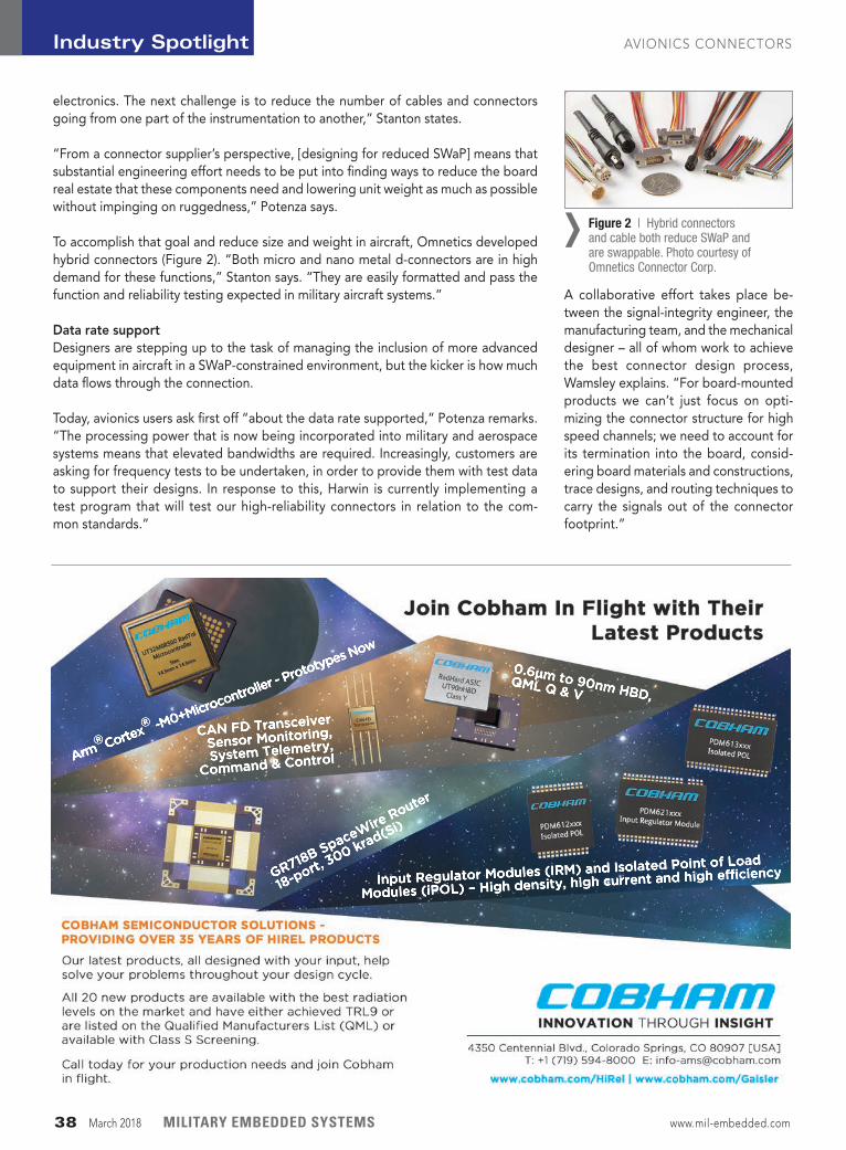
electronics. The next challenge is to reduce the number of cables and connectors going from one part of the instrumentation to another,” Stanton states.
“From a connector supplier’s perspective, [designing for reduced SWaP] means that substantial engineering effort needs to be put into finding ways to reduce the board real estate that these components need and lowering unit weight as much as possible without impinging on rugged ness,” Potenza says.
To accomplish that goal and reduce size and weight in aircraft, Omnetics developed hybrid connectors (Figure 2). “Both micro and nano metal d-connectors are in high demand for these functions,” Stanton says. “They are easily formatted and pass the function and reliability testing expected in military aircraft systems.”
Data rate supportDesigners are stepping up to the task of managing the inclusion of more advanced equipment in aircraft in a SWaP-constrained environment, but the kicker is how much data flows through the connection.
Today, avionics users ask first off “about the data rate supported,” Potenza remarks. “The processing power that is now being incorporated into military and aerospace systems means that elevated bandwidths are required. Increasingly, customers are asking for frequency tests to be undertaken, in order to provide them with test data to support their designs. In response to this, Harwin is currently implementing a test program that will test our high-reliability connectors in relation to the com- mon standards.”
A collaborative effort takes place be- tween the signal-integrity engineer, the manufacturing team, and the mechanical designer – all of whom work to achieve the best connector design process, Wamsley explains. “For board-mounted products we can’t just focus on opti-mizing the connector structure for high speed channels; we need to account for its termination into the board, consid-ering board materials and constructions, trace designs, and routing techniques to carry the signals out of the connector footprint.”
CAN FD Transceiver
Sensor Monitoring,
System Telemetry,
Command & Control
Input Regulator Modules (IRM) and Isolated Point of Load
Modules (iPOL) – High density, high current and high efficiency
0.6µm to 90nm HBD,
QML Q & V
Arm®Cortex
® -M0+Microcontroller - Prototypes Now
GR718B SpaceWire
Router
18-port,
300 krad(Si)
Figure 2 | Hybrid connectors and cable both reduce SWaP and are swappable. Photo courtesy of Omnetics Connector Corp.
›
Industry Spotlight AVIONICS CONNECTORS
38 March 2018 MILITARY EMBEDDED SYSTEMS www.mil-embedded.com
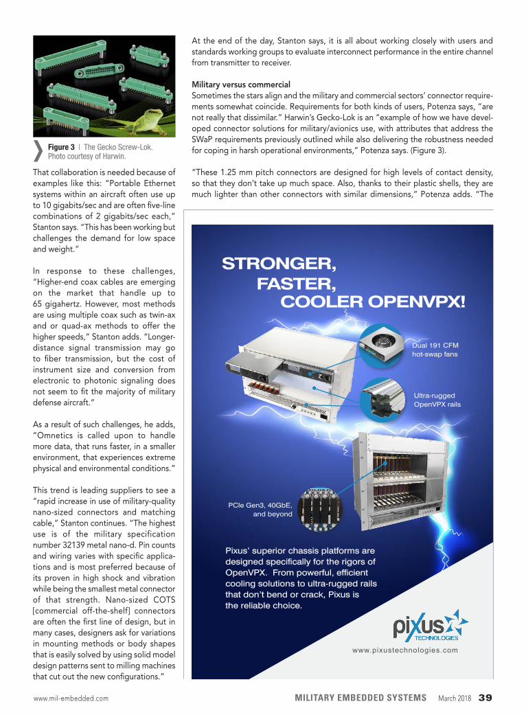
That collaboration is needed because of examples like this: “Portable Ethernet systems within an aircraft often use up to 10 gigabits/sec and are often five-line combinations of 2 gigabits/sec each,” Stanton says. “This has been working but challenges the demand for low space and weight.”
In response to these challenges, “Higher-end coax cables are emerging on the market that handle up to 65 gigahertz. However, most methods are using multiple coax such as twin-ax and or quad-ax methods to offer the higher speeds,” Stanton adds. “Longer-distance signal transmission may go to fiber transmission, but the cost of instrument size and conversion from electronic to photonic signaling does not seem to fit the majority of military defense aircraft.”
As a result of such challenges, he adds, “Omnetics is called upon to handle more data, that runs faster, in a smaller environment, that experiences extreme physical and environmental conditions.”
This trend is leading suppliers to see a “rapid increase in use of military-quality nano-sized connectors and matching cable,” Stanton continues. “The highest use is of the military specification number 32139 metal nano-d. Pin counts and wiring varies with specific applica-tions and is most preferred because of its proven in high shock and vibration while being the smallest metal connector of that strength. Nano-sized COTS [commercial off-the-shelf] connectors are often the first line of design, but in many cases, designers ask for variations in mounting methods or body shapes that is easily solved by using solid model design patterns sent to milling machines that cut out the new configurations.”
At the end of the day, Stanton says, it is all about working closely with users and standards working groups to evaluate interconnect performance in the entire channel from transmitter to receiver.
Military versus commercial Sometimes the stars align and the military and commercial sectors’ connector require-ments somewhat coincide. Requirements for both kinds of users, Potenza says, “are not really that dissimilar.” Harwin’s Gecko-Lok is an “example of how we have devel-oped connector solutions for military/avionics use, with attributes that address the SWaP requirements previously outlined while also delivering the robustness needed for coping in harsh operational environments,” Potenza says. (Figure 3).
“These 1.25 mm pitch connectors are designed for high levels of contact density, so that they don’t take up much space. Also, thanks to their plastic shells, they are much lighter than other connectors with similar dimensions,” Potenza adds. “The
Figure 3 | The Gecko Screw-Lok. Photo courtesy of Harwin.›
www.mil-embedded.com MILITARY EMBEDDED SYSTEMS March 2018 39
Pixus’ superior chassis platforms are designed specifically for the rigors of OpenVPX. From powerful, efficient cooling solutions to ultra-rugged rails that don’t bend or crack, Pixus is the reliable choice.
STRONGER,
www.pixustechnologies.com
FASTER, COOLER OPENVPX!
PCIe Gen3, 40GbE, and beyond
Dual 191 CFM hot-swap fans
Ultra-rugged OpenVPX rails
20180212-RTC-halfpage-Ad-05.indd 1 2/12/18 8:21 PM
Industry Spotlight AVIONICS CONNECTORS
AVIONICS VENDOR LISTINGAbaco Systems www.abaco.com
Access I/O Products Inc. www.accesio.com
Acromag, Inc. www.acromag.com
AdaCore www.adacore.com
ADLINK Technology Inc. www.adlinktech.com
AES Aerospace Embedded Solutions GmbH www.aesolutions.de
AFuzion www.afuzion.com
AirBorn, Inc. www.airborn.com
Aitech Defense Systems, Inc. www.rugged.com
Amphenol Corp. www.amphenol.com
Applied Avionics Inc. www.appliedavionics.com
Astronics Ballard Technology www.astronics.com/ballard
Atrenne Integrated Solutions www.atrenne.com
Averna www.averna.com
Avionics Interface Technologies (A Division of Teradyne)
www.aviftech.com
Cobham www.cobham.com
Core Avionics & Industrial Inc. (CoreAVI) www.coreavi.com
Critical I/O www.criticalio.com
Crystal Group Inc. www.crystalrugged.com
Curtiss-Wright Defense Solutions www.curtisswrightds.com
Data Device Corp. www.ddc-web.com
Dawn VME Products www.dawnvme.com
DDC-I Inc. www.ddci.com
Digital Systems Engineering, Inc. www.digitalsys.com
dSpace GmbH www.dspace.com
Ecrin Systems www.ecrin.com
EIZO Rugged Solutions, Inc. www.eizorugged.com
Elma Electronic www.elma.com
ENSCO Avionics, Inc. www.ensco.com/avionics
Esterline Technologies Corp. www.esterline.com
Excalibur Systems www.mil-1553.com
Fischer Connectors www.fischerconnectors.com
General Micro Systems, Inc. www.gms4sbc.com
GrammaTech, Inc. www.grammatech.com
Great River Technology, Inc. www.greatrivertech.com
Green Hills Software www.ghs.com
Hartmann Electronik www.he-eckental.de
Harwin www.harwin.com
Industrial Electronic Engineers, Inc. (IEE) www.ieeinc.com
Innodisk Corp. www.innodisk.com
Interface Concept www.interfaceconcept.com
Jama Software www.jamasoftware.com
Keysight Technologies www.keysight.com
Kontron www.kontron.com
LDRA www.ldra.com
Lynx Software Technologies, Inc. www.lynx.com
Marvin Test Solutions, Inc. www.marvintest.com
MathWorks, Inc. www.mathworks.com
Memphis Electronic Inc. www.memphis.ag/en/home/
MEN Micro www.menmicro.com
Mentor Graphics www.mentor.com
Mercury Systems, Inc. www.mrcy.com
Microsemi Corp. www.microsemi.com
MilPower Source www.milpower.com
MilSource www.militaryethernet.com
National Instruments www.ni.com
North Atlantic Industries www.naii.com
ODU-USA, Inc. www.odu-usa.com
Omnetics Connector Corp. www.omnetics.com
Orion Technologies www.oriontechnologies.com
Panasonic Avionics Corp. www.panasonic.aero
Parker Aerospace www.parker.com
Pico Electronics, Inc. www.picoelectronics.com
Positronic www.connectpositronic.com
Powerbox International AB www.prbx.com
Presagis www.presagis.com
Rapita Systems Ltd. www.rapitasystems.com
Real-Time Innovations (RTI) www.rti.com
Renesas-Intersil www.intersil.com
Rogue Wave Software, Inc. – Klocwork www.klocwork.com
RTD Embedded Technologies, Inc. www.rtd.com
Scandinavian Avionics A/S www.scanav.com
Sensonor www.sensonor.com
Smiths Interconnect www.smithsconnectors.com
Synopsys, Inc. www.synopsys.com
SYSGO AG www.sysgo.com
Systel Rugged Computers www.systelusa.com
TE Connectivity www.te.com
TTTech Computertechnik AG www.tttech.com
United Electronic Industries www.ueidaq.com
Universal Avionics Systems Corp. www.uasc.com
Vector Software, Inc. www.vectorcast.com
Verocel, Inc. www.verocel.com
Versalogic Corp. www.versalogic.com
Vicor Corp. www.vicorpower.com
VPT, Inc. www.vptpower.com
Wind River www.windriver.com
If you would like to be included on the Military Embedded Systems Avionics Vendor Listing please complete form here: http://bit.ly/2Hc6LJh
40 March 2018 MILITARY EMBEDDED SYSTEMS www.mil-embedded.com
Wamsley explains. “VITA members are driving standards that provide interoperability between system components and developing a broad supply base.
When the user is concerned with data-rate support, “VITA was aimed mostly at heat generated in multiple cables handling high data rates,” Stanton says. “Early seven-row connectors at over 6 gigabits/sec could get hot as cable length increased.”
“From a connector perspective, we develop building-block solutions for high-speed digital, RF, optics, and power interconnect that can be implemented in a common form factor but are tailored for the application,” Wamsley says. “The OpenVPX stan-dard interconnects are used in space and ground vehicles, shipboard systems, a wide range of applications, so that avionics customers can leverage standard solutions from a much broader market. As a result, we manufacture more standard connectors and fewer customized solutions, improving our operational efficiency and reducing overall costs to the user.” MES
screw-locking mechanism means that they can withstand heavy vibrational forces. Because of these characteristics, this product has seen widespread use in UAV design, as well as other military applications where SWaP is a key factor.”
A difference between military and com-mercial lies within the architecture or standard when designing avionics con-nectors. “Military avionics customers commonly use backplane architecture such as VPX for embedded computing system design,” Wamsley explains. “Commercial avionics often follow ARINC standards with a rack-and-panel application, using cabling instead of a backplane to communicate between modules within the system.”
Where it really counts is delivering a reli-able connection to both users: “The high reliability requirements are effectively the same, but there is the compliance with the relevant military standards to be factored in, of course,” Potenza says.
While suppliers and users alike need to “keep within budget (and are to some degree influenced by the LPTA initia-tive [the lowest price technically accept-able]), military contractors are now looking to source COTS solutions when-ever that is applicable,” Potenza adds.
“However, we are seeing more migra-tion of solutions to cover both military and commercial environments,” Wamsley says. “Outside the box, some common I/O connector interfaces such as MIL- DTL-38999 connectors are used for military and commercial avionics. Envi- ronmental requirements are generally harsher – salt spray, dust, rad-hard – for defense applications, but good connector design practices for harsh environments are followed for both markets.”
VITA standardsIn a world where the focus is on deliv-ering the best technology to the war-fighter, designing to and enabling standards like VITA only helps to achieve that goal.
“OpenVPX is a rapidly emerging open standard architecture that is being adopted for many new avionics sys-tems and upgrades,” TE Connectivity’s
www.mil-embedded.com MILITARY EMBEDDED SYSTEMS March 2018 41
NEW!
Key Features Include:
▪ A/D, D/A, serial, digital I/O, counter/timer, Ethernet and FPGA
▪ Low-power consumption
▪ Solid-state electronics
▪ -40 to 85°C standard operating temperature
▪ Conduction cooled models available
▪ Mix-and-match endless I/O combinations in a single slot by using our XMC, VPX or PCIe-based carriers
The AcroPack product line updates our popular Industry Pack I/O modules by using the mPCIe interface format. We added 19mm and a 100-pin connector to provide up to 50 isolated rear I/O signals, giving you a tremendous amount of capability on an Extremely Small Footprint - Without Cabling!
Embedded I/O Solutions for the Next 25 Years
Embedded I/O Solutions
Visit Acromag.com/AcroPacksTO LEARN MORE
Mini PCIe Gets an Upgrade
FPGA Modules SFF Embedded ComputersAcroPack® I/O ModulesEthernet Remote I/O Modules
AcroPack modules snap onto AcroPack PCIe, XMC & VPX carriers, eliminating ribbon cables.
These modules are just 70mm long.
www.acromag.com | [email protected] | 877-295-7088
=AcroPacks® S a -W P C
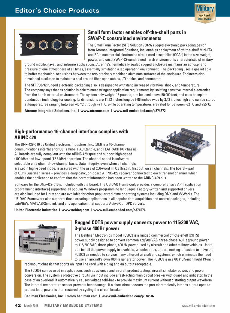
Rugged COTS power supply converts power to 115/200 VAC, 3-phase 400Hz powerThe Behlman Electronics model FC5003 is a rugged commercial off-the-shelf (COTS) power supply designed to convert common 120/208 VAC, three-phase, 60 Hz ground power to 115/200 VAC, three-phase, 400 Hz power used by aircraft and other military vehicles. Users can install the power supply in a vehicle, wheeled rack, or cart, making it feasible to move the FC5003 as needed to service many different aircraft and systems, which eliminates the need to use an aircraft’s own 400 Hz generator power. The FC5003 is in a 6U (10.5-inch high) 19-inch
rackmount chassis that sports an input line cord with a plug and an output receptacle.
The FC5003 can be used in applications such as avionics and aircraft product testing, aircraft simulator power, and power conversion. The system’s protective circuits via input include a fast-acting main circuit breaker with guard and indicator. In the case of an overload, it automatically causes voltage fold-back to provide maximum current without distorting output waveform. The internal temperature sensor prevents heat damage. If a short circuit occurs the part electronically latches output open to protect load; power is then restored by cycling the circuit breaker.
Behlman Electronics, Inc | www.behlman.com | www.mil-embedded.com/p374576
Small form factor enables off-the-shelf parts in SWaP-C constrained environments The Small Form Factor (SFF) Solution 760-92 rugged electronic packaging design from Atrenne Integrated Solutions, Inc. enables deployment of off-the-shelf Mini-ITX and PCIe commercial electronics circuit card assemblies (CCAs) in the size, weight, power, and cost (SWaP-C)-constrained harsh environments characteristic of military
ground mobile, naval, and airborne applications. Atrenne’s hermetically sealed rugged enclosure maintains an atmospheric pressure of one atmosphere at all times, essentially simulating a lab operating environment. The packaging uses a gasket able to buffer mechanical occlusions between the two precisely machined aluminum surfaces of the enclosure. Engineers also developed a solution to maintain a seal around fiber-optic cables, I/O cables, and connectors.
The SFF 760-92 rugged electronic packaging also is designed to withstand increased vibration, shock, and temperature. The company says that its solution is able to meet stringent application requirements by isolating sensitive internal electronics from the harsh external environment. The system only weighs 13 pounds, can be used above 50,000 feet, and uses baseplate conduction technology for cooling. Its dimensions are 11.22 inches long by 9.06 inches wide by 3.43 inches high and can be stored at temperatures ranging between -40 °C through +71 °C, while operating temperatures are rated for between -32 °C and +55°C.
Atrenne Integrated Solutions, Inc. | www.atrenne.com | www.mil-embedded.com/p374572
Editor’s Choice Products
High-performance 16-channel interface complies with ARINC 429The DNx-429-516 by United Electronic Industries, Inc. (UEI) is a 16-channel communications interface for UEI’s Cube, RACKtangle, and FLATRACK I/O chassis. All boards are fully compliant with the ARINC 429 spec and support high-speed (100 kHz) and low-speed (12.5 kHz) operation. The channel speed is software-selectable on a channel-by-channel basis. Data integrity, even when all channels are set in high-speed mode, is assured with the use of 256-word FIFOs [first in, first out] on all channels. The board – part of UEI’s Guardian series – provides a diagnostic, on-board ARINC-429 receiver connected to each transmit channel, which enables the application to confirm that the correct information has been written to the ARINC-429 bus.
Software for the DNx-429-516 is included with the board: The UEIDAQ Framework provides a comprehensive API [application programming interface] supporting all popular Windows programming languages. Factory-written and supported drivers are also included for Linux and are available for other popular real-time operating systems including QNX and VxWorks. The UEIDAQ Framework also supports those creating applications in all popular data acquisition and control packages, including LabVIEW, MATLAB/Simulink, and any application that supports ActiveX or OPC servers.
United Electronic Industries | www.ueidaq.com | www.mil-embedded.com/p374574
42 March 2018 MILITARY EMBEDDED SYSTEMS www.mil-embedded.com
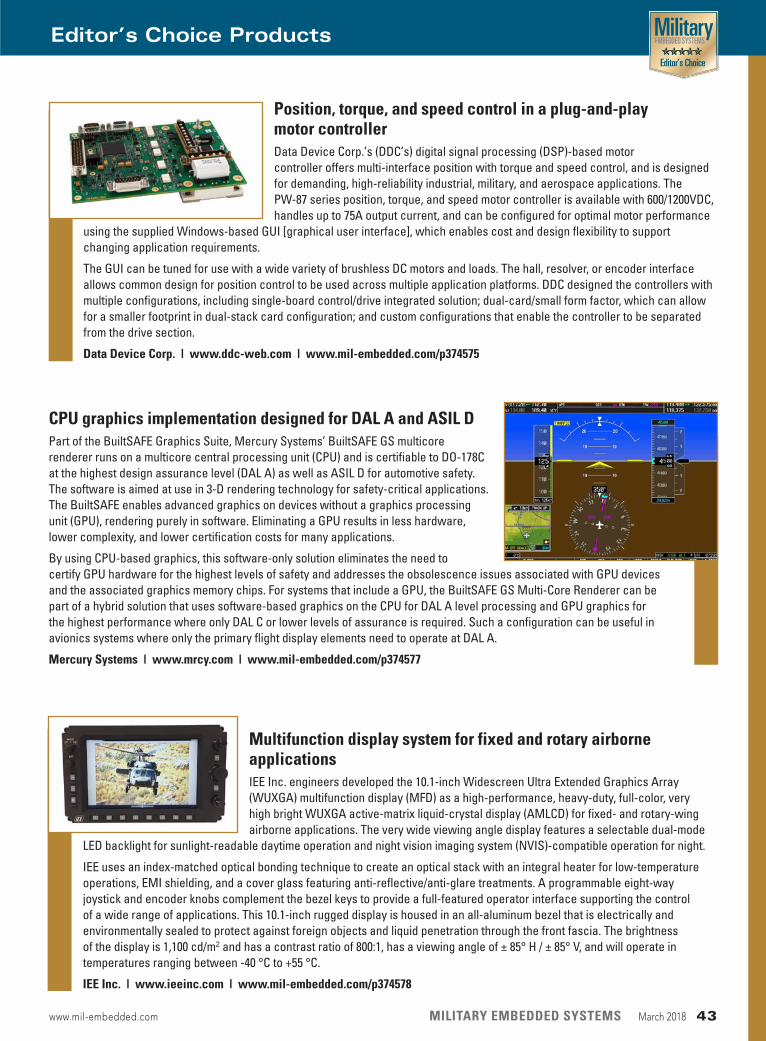
CPU graphics implementation designed for DAL A and ASIL DPart of the BuiltSAFE Graphics Suite, Mercury Systems’ BuiltSAFE GS multicore renderer runs on a multicore central processing unit (CPU) and is certifiable to DO-178C at the highest design assurance level (DAL A) as well as ASIL D for automotive safety. The software is aimed at use in 3-D rendering technology for safety-critical applications. The BuiltSAFE enables advanced graphics on devices without a graphics processing unit (GPU), rendering purely in software. Eliminating a GPU results in less hardware, lower complexity, and lower certification costs for many applications.
By using CPU-based graphics, this software-only solution eliminates the need to certify GPU hardware for the highest levels of safety and addresses the obsolescence issues associated with GPU devices and the associated graphics memory chips. For systems that include a GPU, the BuiltSAFE GS Multi-Core Renderer can be part of a hybrid solution that uses software-based graphics on the CPU for DAL A level processing and GPU graphics for the highest performance where only DAL C or lower levels of assurance is required. Such a configuration can be useful in avionics systems where only the primary flight display elements need to operate at DAL A.
Mercury Systems | www.mrcy.com | www.mil-embedded.com/p374577
Editor’s Choice Products
Position, torque, and speed control in a plug-and-play motor controllerData Device Corp.’s (DDC’s) digital signal processing (DSP)-based motor controller offers multi-interface position with torque and speed control, and is designed for demanding, high-reliability industrial, military, and aerospace applications. The PW-87 series position, torque, and speed motor controller is available with 600/1200VDC, handles up to 75A output current, and can be configured for optimal motor performance
using the supplied Windows-based GUI [graphical user interface], which enables cost and design flexibility to support changing application requirements.
The GUI can be tuned for use with a wide variety of brushless DC motors and loads. The hall, resolver, or encoder interface allows common design for position control to be used across multiple application platforms. DDC designed the controllers with multiple configurations, including single-board control/drive integrated solution; dual-card/small form factor, which can allow for a smaller footprint in dual-stack card configuration; and custom configurations that enable the controller to be separated from the drive section.
Data Device Corp. | www.ddc-web.com | www.mil-embedded.com/p374575
Multifunction display system for fixed and rotary airborne applications IEE Inc. engineers developed the 10.1-inch Widescreen Ultra Extended Graphics Array (WUXGA) multifunction display (MFD) as a high-performance, heavy-duty, full-color, very high bright WUXGA active-matrix liquid-crystal display (AMLCD) for fixed- and rotary-wing airborne applications. The very wide viewing angle display features a selectable dual-mode
LED backlight for sunlight-readable daytime operation and night vision imaging system (NVIS)-compatible operation for night.
IEE uses an index-matched optical bonding technique to create an optical stack with an integral heater for low-temperature operations, EMI shielding, and a cover glass featuring anti-reflective/anti-glare treatments. A programmable eight-way joystick and encoder knobs complement the bezel keys to provide a full-featured operator interface supporting the control of a wide range of applications. This 10.1-inch rugged display is housed in an all-aluminum bezel that is electrically and environmentally sealed to protect against foreign objects and liquid penetration through the front fascia. The brightness of the display is 1,100 cd/m2 and has a contrast ratio of 800:1, has a viewing angle of ± 85° H / ± 85° V, and will operate in temperatures ranging between -40 °C to +55 °C.
IEE Inc. | www.ieeinc.com | www.mil-embedded.com/p374578
www.mil-embedded.com MILITARY EMBEDDED SYSTEMS March 2018 43
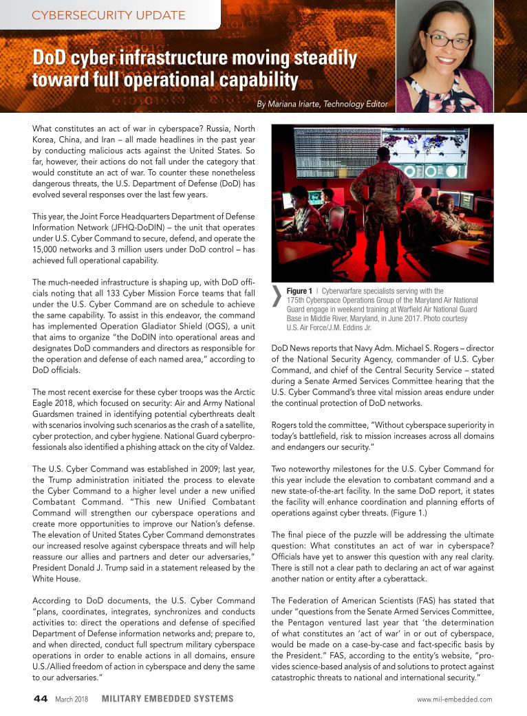
What constitutes an act of war in cyberspace? Russia, North Korea, China, and Iran – all made headlines in the past year by conducting malicious acts against the United States. So far, however, their actions do not fall under the category that would constitute an act of war. To counter these nonetheless dangerous threats, the U.S. Department of Defense (DoD) has evolved several responses over the last few years.
This year, the Joint Force Headquarters Department of Defense Information Network (JFHQ-DoDIN) – the unit that operates under U.S. Cyber Command to secure, defend, and operate the 15,000 networks and 3 million users under DoD control – has achieved full operational capability.
The much-needed infrastructure is shaping up, with DoD offi-cials noting that all 133 Cyber Mission Force teams that fall under the U.S. Cyber Command are on schedule to achieve the same capability. To assist in this endeavor, the command has implemented Operation Gladiator Shield (OGS), a unit that aims to organize “the DoDIN into operational areas and designates DoD commanders and directors as responsible for the operation and defense of each named area,” according to DoD officials.
The most recent exercise for these cyber troops was the Arctic Eagle 2018, which focused on security: Air and Army National Guardsmen trained in identifying potential cyberthreats dealt with scenarios involving such scenarios as the crash of a satellite, cyber protection, and cyber hygiene. National Guard cyberpro-fessionals also identified a phishing attack on the city of Valdez.
The U.S. Cyber Command was established in 2009; last year, the Trump administration initiated the process to elevate the Cyber Command to a higher level under a new unified Combatant Command. “This new Unified Combatant Command will strengthen our cyberspace operations and create more opportunities to improve our Nation’s defense. The elevation of United States Cyber Command demonstrates our increased resolve against cyberspace threats and will help reassure our allies and partners and deter our adversaries,” President Donald J. Trump said in a statement released by the White House.
According to DoD documents, the U.S. Cyber Command “plans, coordinates, integrates, synchronizes and conducts activities to: direct the operations and defense of specified Department of Defense information networks and; prepare to, and when directed, conduct full spectrum military cyberspace operations in order to enable actions in all domains, ensure U.S./Allied freedom of action in cyberspace and deny the same to our adversaries.”
DoD News reports that Navy Adm. Michael S. Rogers – director of the National Security Agency, commander of U.S. Cyber Command, and chief of the Central Security Service – stated during a Senate Armed Services Committee hearing that the U.S. Cyber Command’s three vital mission areas endure under the continual protection of DoD networks.
Rogers told the committee, “Without cyberspace superiority in today’s battlefield, risk to mission increases across all domains and endangers our security.”
Two noteworthy milestones for the U.S. Cyber Command for this year include the elevation to combatant command and a new state-of-the-art facility. In the same DoD report, it states the facility will enhance coordination and planning efforts of operations against cyber threats. (Figure 1.)
The final piece of the puzzle will be addressing the ultimate question: What constitutes an act of war in cyberspace? Officials have yet to answer this question with any real clarity. There is still not a clear path to declaring an act of war against another nation or entity after a cyberattack.
The Federation of American Scientists (FAS) has stated that under “questions from the Senate Armed Services Committee, the Pentagon ventured last year that ‘the determination of what constitutes an ‘act of war’ in or out of cyberspace, would be made on a case-by-case and fact-specific basis by the President.” FAS, according to the entity’s website, “pro-vides science-based analysis of and solutions to protect against catastrophic threats to national and international security.”
44 March 2018 MILITARY EMBEDDED SYSTEMS www.mil-embedded.com
Figure 1 | Cyberwarfare specialists serving with the 175th Cyberspace Operations Group of the Maryland Air National Guard engage in weekend training at Warfield Air National Guard Base in Middle River, Maryland, in June 2017. Photo courtesy U.S. Air Force/J.M. Eddins Jr.
›
DoD cyber infrastructure moving steadily toward full operational capability
CYBERSECURITY UPDATE
By Mariana Iriarte, Technology Editor
By Russ Doty, Red Hat
Five tips for protecting against wireless KRACK
The recent KRACK (Key Reinstallation Attacks) attack on the Wi-Fi WPA2 secu-rity protocols (CVE-2017-13077 through CVE-2017-13088) highlights the require-ment to actively maintain and update embedded systems, especially long-life systems deployed in hostile environments.
KRACK is interesting because it is a flaw in a mature, widely used security protocol. KRACK exploits a flaw in the four-way handshake Wi-Fi devices use to establish encrypted communications using WPA2. Fortunately, there is a backwards-compatible fix for this vulner-ability; patching either end of the Wi-Fi link fixes the problem.
Rather than going into the details of KRACK, I would like to use this as a case study – and a lesson plan – for those tasked with managing connectivity and embedded systems.
Problems will be found in all systemsFirst, problems will be found in all sys-tems. Increasing computing power allows crypto algorithms and key lengths to be attacked. We have seen this in every-thing from the deprecation of the old DES encryption standard to the evolu-tion of RSA key lengths to the currently recommended 2048-bit or longer keys. Even with a secure algorithm, implemen-tation flaws and novel methods of attack can create vulnerabilities. Consider the various weaknesses discovered in the OpenSSL code as one example. Com- munications protocols may have weak-nesses which may only be discovered after years of use, such as the Wi-Fi KRACK, which affects billions of devices.
Plan for failure plus remediation and updatesThe biggest lesson of KRACK is that you must plan for failure and have a way to remediate and update your systems. Period. No exceptions. Sitting on my desk is a Wi-Fi lightbulb – cost less than $20, with a full Wi-Fi stack that connects to the network. This device is vulnerable
to the KRACK attack and will never be updated – the only way to remediate the exposure is to throw it away. (I should note that this lightbulb has other secu-rity holes, which is why it is sitting on my desk rather than screwed into a socket.) While somewhat plausible for low-cost consumer devices, discarding a working device is a poor approach that is com-pletely unacceptable for any significant system. In contrast, vendors of Wi-Fi routers and access points, cellphones, tablets, and laptops have quickly released patches for KRACK. (Have you updated all of your Wi-Fi devices yet?)
A vital part of patching is knowing what systems need to be patched. You need a way to tell what is installed on a system and whether it is vulnerable. System scanning needs to cover what software is installed, the versions, and configuration.
Encrypt important communications Yes, WPA2 encrypts data – but only for the Wi-Fi link. Full end-to-end encryp-tion is needed, such as that provided by SSL/TLS (please use TLS 1.1 or 1.2 and prevent session downgrades to lower versions) or a VPN [virtual private net-work]. The applications running on an embedded system should be respon-sible for their own encryption rather than trusting the network to encrypt itself. This means that the application stack should be using a standard supported encryption mechanism like SSL/TLS or a VPN and ensuring that it is properly con-figured, not that the application needs to include encryption directly inside the application. If you do include crypto inside an application, use standard cryp-topackages and libraries. Never try to build your own cryptoimplementation; that doesn’t end well...
Maintain tight access controlA mechanism is needed to detect, iden-tify, authorize, and enroll all devices attempting to connect to your network. Ironically, access control is a major part
of WPA2, using the “Wi-Fi password” as a shared secret. WPA2 actually does this rather well, and continues to do it well after being patched for KRACK. Other tools are available for other interfaces, ranging from simple Bluetooth pairing to complex attestation using Secure Boot or Trusted Boot for servers.
Exploiting communication vulnerabilities requires access. KRACK requires you to be physically close to your target.
Use a hard-wired Ethernet connectionThis has been recommended by many sources as an effective way to remediate KRACK, especially for desktop and laptop systems. This could be as simple as a desktop Ethernet switch and some patch cables to use temporarily until you can patch your devices, or it could be a wired building with Ethernet drops in each office and laptop docking stations.
When considering system design, re- member the key differences between and benefits of wireless and wired devices. Wireless devices are easy and inexpensive to install, easy to move, and easy to add more devices and connec-tions. Wired devices typically cost more to install, are difficult to move, may be difficult to add more devices (since more communications ports are required), and are usually faster, more reliable, and more secure. Wired interfaces require direct physical access for communica-tions, and typically emit little or no elec-tromagnetic radiation.
Communications is a key part of most embedded systems. While KRACK is specific to Wi-Fi WPA2, similar concerns apply to all forms of wireless interfaces – actually to all interfaces, wired or wire-less. Enabling the security and integrity of communications is a part of the design, implementation, and life cycle management of these systems.
Russell Doty is a technology strategist and product manager at Red Hat.
www.mil-embedded.com MILITARY EMBEDDED SYSTEMS March 2018 45
BLOG
46 March 2018 MILITARY EMBEDDED SYSTEMS www.mil-embedded.com
CHARITY
Children of Fallen PatriotsEach issue in this section, the editorial staff of Military Embedded Systems will highlight a different charity that benefits military veterans and their families. We are honored to cover the technology that protects those who protect us every day. To back that up, our parent company – OpenSystems Media – will make a donation to every charity we showcase on this page.
This issue we are highlighting the Children of Fallen Patriots foundation, a nonprofit national organization that focuses on funding college scholarships and educational counseling for children who have lost a parent in the line of military duty.
The foundation was started in 2002 by former Army artillery officer David Y. Kim, who participated in Operation Just Cause in Panama in 1989 with the 7th Infantry Division. Kim – an honors graduate of West Point and the Harvard Business School – was inspired by the patriotism of his fallen comrades and pledged to aid the children of Gold Star families in all 50 states and from all branches of the military.
The founders of the Children of Fallen Patriots, according to information from the organization, believe that a college education is the single most important gift these children can receive, that this is an important investment in the future of America, and that it is one of the best ways we can honor those who died defending our country.
While nearly all of the students the foundation serves also receive educational benefits from the Department of Veteran’s Affairs benefits, this aid does not cover all of the needs of any given scholar. Because the foundation understands that tuition is not the only expense related to college, Children of Fallen Patriots assists with various living expenses, including such costs as room and board, transportation, health insurance, and internet expenses.
For more information on Children of Fallen Patriots, please visit www.fallenpatriots.org.
WHITE PAPER
VPX Power Conversion GuideBy Milpower Source
The VPX form factor is quickly becoming a tool engineers may leverage to address many of the standardization challenges they face. Engineers must hew to the specs of such mature standards as MIL-STD-704 and MIL-STD-1275 (which define electrical power characteristics) or MIL-STD-461 (which characterizes electromagnetic interference), all of which carry standardized design practices for engineers.
In this white paper, power-supply designers, systems engineers, procurement specialists, and program managers will find a list of considerations to keep in mind when sourcing a VPX power supply.
In many cases, commercial off-the-shelf (COTS) VITA-compliant VPX products can be tailored to meet the unique and challenging requirements of the integrator, often with little or no nonrecurring engineering (NRE) costs.
Read the white paper: http://www.embedded-computing.com/military-white-papers/milpower-source-white-paper-jan
Read more white papers: http://mil-embedded.com/white-papers/
Enabling open architectures and commonality in military systemsSponsored by Annapolis Micro Systems, Kontron, Mercury, and National Instruments
The demand for commonality is driving procurement and technology development within the Department of Defense (DoD) – from radar and electronic warfare to intel-ligence, surveillance, and reconnaissance (ISR) sensors and avionics.
In this e-cast, industry experts discuss how various DoD open-architecture initiatives – such as the Sensor Open Systems Architecture (SOSA) and Hardware Open Systems Technologies (HOST) – are working together to shorten fielding times, lower life cycle costs, leverage economies of scale, and promote reuse for Army, Air Force, Navy, and Marine Corps platforms.
View archived e-cast: ecast.opensystemsmedia/791
View more e-casts: http://opensystemsmedia.com/events/e-cast/schedule
E-CAST
www.mil-embedded.com
CONNECTING WITH MIL EMBEDDED
CHARITIES | MARKET PULSE | WHITE PAPER | BLOG | VIDEO | SOCIAL MEDIA | E-CAST
By Mil-Embedded.com Editorial Staff
LEARN HOW YOU CAN SHAPE THE FUTURE AT VITA.COM
VITA members have built an open path for the critical and intelligent systems of tomorrow — rugged, reliable, real world systems that have propelled embedded computing forward for more than three decades.
The world depends on VITA Technologies for open standards that help defi ne safety, control, defense, communications, entertainment, transportation, and many other applications. Critical and intelligent embedded systems are everywhere…become a leader in setting new directions!
HOW WILL YOU SHAPE CRITICAL AND INTELLIGENT EMBEDDED COMPUTING?
Intelligently record wideband signals continuously...for hours
Pentek, Inc., One Park Way, Upper Saddle River, NJ 07458 Phone: 201-818-5900 • Fax: 201-818-5904 • email: [email protected] • www.pentek.comWorldwide Distribution & Support, Copyright © 2016 Pentek, Inc. Pentek, Talon, SystemFlow, Sentinel and QuickPac are trademarks of Pentek, Inc. Other trademarks are properties of their respective owners.
Capture. Record. Real-Time. Every Time.
Download the FREE High-Speed Recording Systems Handbook at: www.pentek.com/go/mestalonor call 201-818-5900 for additional information.
Capturing critical SIGINT, radar and communications signals requires hardware highly-optimized for precision and performance. Our COTS Talon® recording systems deliver the industry’s highest levels of performance, even in the harshest environments. You’ll get extended operation, high dynamic range and exceptional recording speed every time!
• High-speed, real-time recording: Sustained data capture rates to 8 GB/sec • Extended capture periods: Record real-time for hours or days with storage up to 100+ TB • Exceptional signal quality: Maintain highest dynamic range for critical signals • Flexible I/O: Capture both analog and digital signals• Operational in any environment: Lab, rugged, fl ight-certifi ed, portable and SFF systems designed for SWaP• Out-of-the-box operation: SystemFlow® GUI, signal analyzer and API provide simple instrument interfaces• Intelligent recording: Sentinel™ Intelligent Scan and Capture software automatically detects and records signals of interest
Eight SSD QuickPac™ canister, removable in seconds!


![Lecture #23 Real Time Operating Systemsece348/lectures/23_rtos_swQuality_hand… · Source: [Hawley03] Selecting a Real-Time Operating System, Embedded.com Build vs. buy • Don’t](https://img.pdfslide.us/doc/110x75/5f165a4ac9c23400764f7314/lecture-23-real-time-operating-ece348lectures23rtosswqualityhand-source.jpg)


![DN Blurbs By Department – June 18, 2007 · Web view[INSERT PHOTO OF HERB] HERBERT C. WAMSLEY TO GIVE LUNCHEON ADDRESS AT IPO ANNUAL MEETING – On September 29, 2015, Herbert Wamsley](https://img.pdfslide.us/doc/110x75/5e3fd1c617dd7876940f20d6/dn-blurbs-by-department-a-june-18-2007-web-view-insert-photo-of-herb-herbert.jpg)