Embed Size (px)
Citation preview
MIL-HDBK-1012/115 MAY 1989SUPERSEDING DM-12.1APRIL 1983
MILITARY HANDBOOK
ELECTRONIC FACILITIES ENGINEERING
AMSC N/A
DISTRIBUTION STATEMENT A. APPROVED FOR PUBLIC RELEASE: DISTRIBUTION ISUNLIMITED
AREA FACR

MIL-HDBK-1012/1
THIS PAGE INTENTIONALLY LEFT BLANK

MIL-HDBK-1012/1
ABSTRACT
This military handbook presents design criteria for Category Codes 131and 132, communication facilities, antennas, and transmission lines. Thecontents cover general engineering requirements, as well as specificrequirements for the major types of electronic facilities, including automaticdata processing centers and transportables. The design criteria are intendedfor use by experienced architects and engineers.
iii

MIL-HDBK-1012/1
THIS PAGE INTENTIONALLY LEFT BLANK

MIL-HDBK-1012/1
FOREWORD
This handbook has been developed from an evaluation of facilities in theshore establishment, from surveys of the availability of new materials andconstruction methods, and from selection of the best design practices of theNaval Facilities Engineering Command (NAVFACENGCOM), other Governmentagencies, and the private sector. This handbook was prepared using, to themaximum extent feasible, national professional society, association, andinstitute standards. Deviations from these criteria in the planning,engineering, design, and construction of Naval shore facilities cannot be madewithout prior approval of NAVFACENGCOM HQ (Code 04).
Design cannot remain static any more than can the naval functions it serves orthe technologies it uses. Accordingly, recommendations for improvement areencouraged and should be furnished to Commanding Officer, Chesapeake Division,Naval Facilities Engineering Command, Code 406C, Washington, DC 20374-2121.Telephone (202) 433-3314.
THIS HANDBOOK SHALL NOT BE USED AS A REFERENCE DOCUMENT FOR PROCUREMENT OFFACILITIES CONSTRUCTION. IT IS TO BE USED IN THE PURCHASE OF FACILITIESENGINEERING STUDIES AND DESIGN (FINAL PLANS, SPECIFICATIONS, AND COST ESTIMATES). DO NOT REFERENCE IT IN MILITARY OR FEDERAL SPECIFICATIONS OROTHER PROCUREMENT DOCUMENTS.
V

CriteriaManual
MIL-HDBK-1012/1
DM-12.02
MIL-HDBK-1012/1
ELECTRONIC FACILITIES CRITERIA MANUALS
Title
Electronic Facilities Engineering
High Altitude Electromagnetic PulseProtection for Ground-Based Facilities
PA
CHESDIV
CHESDIV
V i
MIL-HDBK-1012/1
ELECTRONIC FACILITIES ENGINEERING
CONTENTS
Page
Section 1Section 11.11.11.21.21.31.31.3.11.3.11.3.21.3.21.3.31.3.31.3.41.3.41.3.51.41.41.51.51.5.11.5.11.5.1.11.5.1.11.5.1.21.5.1.2
Section 22.12.22.2.12.2.22.32.3.12.3.22.42.52.62.72.82.92.102.10.12.10.22.10.32.10.42.112.11.12.11.22.11.32.11.42.122.12.12.12.22.12.32.12.42.12.52.13
SITE CONSIDERATIONSSuitability of the Site . . . . . . . . . . . . . . . . 3Relationship to Design . . . . . . . . . . . . . . . . 3Site Selection Survey . . . . . . . . . . . . . . . . . 3Electromagnetic Compatibility (EMC) Evaluation . . . . 3Isolation . . . . . . . . . . . . . . . . . . . . . . . . 3Buffer Zones . . . . . . . . . . . . . . . . . . . . . 6Other Considerations . . . . . . . . . . . . . . . . . 6Expansion. . . . . . . . . . . . . . . . . . . . . . . 6Siting Procedure . . . . . . . . . . . . . . . . . . . 6Site Plan Components . . . . . . . . . . . . . . . . . 6Survey Base Line . . . . . . . . . . . . . . . . . . . 6Layout . . . . . . . . . . . . . . . . . . . . . . . . 6Site Security Considerations . . . . . . . . . . . . . 7Surface and Subsurface Drainage . . . . . . . . . . . . 7Runoff . . . . . . . . . . . . . . . . . . . . . . . . 7Pipes . . . . . . . . . . . . . . . . . . . . . . . . . 7Drainage . . . . . . . . . . . . . . . . . . . . . . . 7Exceptions . . . . . . . . . . . . . . . . . . . . . . 7Paved Areas. . . . . . . . . . . . . . . . . . . . . . 7Traffic Areas . . . . . . . . . . . . . . . . . . . . . 7Roads. . .. . . . . . . . . . . . . . . . . . . . . . 7C u r b s . . . . . . . . . . . . . . . . . . . . . . . . . 9Guardrails . . . . . . . . . . . . . . . . . . . . . . 9Water Supply and Wastewater Disposal. . . . . . . 9Water Supply . . . . . . . . . . . . . . . . . . . . . 9Pipe . . . . . . . . . . . . . . . . . . . . . . . . . 9Lawn Irrigation . . . . . . . . . . . . . . . . . . . . . 9Fire Protection . . . . . . . . . . . . . . . . . . . . 9Conformance to Regulations . . . . . . . . . . . . . . 9Landscaping and Ground Cover . . . . . . . . . . . 9
INTRODUCTIONS c o p e . . . . . . . . . . . . . . . . . . . .Cancellation . . . . . . . . . . . . . . . .ResponsibilitiesChief of Naval Operations (CNO) . . . . . . .Naval Facilities Engineering Command (NAVFAC)Space Naval Warfare Systems Command (SPAWAR)Maintenance Authority . . . . . . . . . . . .Designer . . . . . . . . . . . . . . . . . .Policy . . . . . . . . . . . . . . . . . . .Principal Data Sources . . . . . . . . . . .BESEP . . . . . . . . . . . . . . . . . . . . .General Requirements . . . . . . . . . . . .Design Data . . . . . . . . . . . . . . . . .
. . . . . 1
. . . . . 1
. . . . . 1
. . . . . 1
. . . . . 1
. . . . . 1
. . . . . 1
. . . . . 1
. . . . . 2
. . . . . 2
. . . . . 2
. . . . . 2
. . . . . 2
V i i

MIL-HDBK-1012/1
2.13.1 Placement . . . . . . . . . . . . . . . . . . . . . . . 9 2.13.2 Fire Breaks . . . . . . . . . . . . . . . . . . . . . . . . 92.14 Fencing, Gates, and Guard Towers. . . . . . . . . . . 9
Section 33.13.1.13.1.23.1.33.23.2.13.2.23.33.43.4.13.4.23.53.5.13.5.23.63.73.83.8.13.8.2
3.8.33.8.4
ARCHITECTURAL AND STRUCTURAL ENGINEERINGBasic Construction Criteria. . . . . . . . . . . . . .General Requirements. . . . . . . . . . . . . . . . . .Equipment Spaces . . . . . . . . . . . . . . . . . . .Special Requirements . . . . . . . . . . . . . . . . .Structural Design. . . . . . . . . . . . . . . . . .Foundations . . . . . . . . . . . . . . . . . . . . .Framing . . . . . . . . . . . . . . . . . . . . . . .Exterior Walls. . . . . . . . . . . . . . . . . . . .Interior Walls. . . . . . . . . . . . . . . . . . . .Permanent Partitions . . . . . . . . . . . . . . . . .Nonpermanent Partitions . . . . . . . . . . . . . . .Floors . . . . . . . . . . . . . . . . . . . . . . . .Permanent Floors . . . . . . . . . . . . . . . . . . .Raised Floors . . . . . . . . . . . . . . . . . . . .Roofs . . . . . . . . . . . . . . . . . . . . . . . . .Ceilings . . . . . . . . . . . . . . . . . . . . . . .Finishes . . . . . . . . . . . . . . . . . . . . . . .Operating Areas Housing Electronic Equipment. . .Storage Spaces, Vaults, and Mechanical EquipmentRooms. . . . . . . . . . . . . . . . . . . . . . . .
Offices, Corridors, and Toilets. . . . . . . . . . .Other Spaces . . . . . . . . . . . . . . . . . . . . . .
1111111111111212121212i2121212131313
131313
Section 44.14.2
MECHANICAL ENGINEERINGGeneral . . . . . . . . . . . . . . . . . . . . . . .Heating, Ventilating, and Air Conditioning(HVAC) Systems . . . . . . . . . . . . . . . . . . .
Outside Design Conditions . . . . . . . . . . . . . . .Permanent and Transportable/NonrelocatableFacilities . . . . . . . . . . . . . . . . . . . . .
Transportable/Tactical and Transportable/RelocatableFacilities. . . . . . . . . . . . . . . . . . . . . .
Inside Design Conditions. . . . . . . . . . . . . . .Computer Rooms . . . . . . . . . . . . . . . . . . . .Receiver Buildings and Similar Areas .........Transmitter Buildings. . . . . . . . . . . . . . . .Uninterruptible Power Supply (UPS) Equipment Rooms . .UPS and Microwave Equipment Battery Rooms. . . .Emergency Generator Rooms . . . . . . . . . . . . . .Transportables . . . . . . . . . . . . . . . . . . . .Guidelines for HVAC System Design . . . . . . . . .Simplicity. . . . . . . . . . . . . . . . . . . . . .Equipment Selection . . . . . . . . . . . . . . . . .Fuel Selection . . . . . . . . . . . . . . . . . . . .Humidification . . . . . . . . . . . . . . . . . . . . .Dehumidification . . . . . . . . . . . . . . . . . . .
14
4.2.14.2.1.1
1414
14
4.2.1.2
4.2.24.2.2.14.2.2.24.2.2.34.2.2.44.2.2.54.2.2.64.2.2.74.2.34.2.3.14.2.3.24.2.3.34.2.3.44.2.3.5
141414141415151616161616161717
V i i i
Page
MIL-HDBK-1012/1
4.2.3.64.2.3.74.2.3.84.2.44.2.4.14.2.4.24.2.4.34.2.4.44.34.3.14.3.24.3.34.44.4.14.4.24.4.2.14.4.2.24.4.2.34.4.2.4
Section 55.15.25.2.15.2.25.2.2.15.2.2.25.2.2.35.2.2.45.2.2.55.2.2.65.2.2.75.2.35.2.3.15.2.3.25.2.3.35.2.3.45.2.3.55.2.45.2.55.2.65.2.6.15.2.6.25.2.75.2.85.2.8.15.2.8.25.2.8.35.2.8.45.2.8.55.2.8.6
Air Distribution . . . . . . . . . . . . . . . .Air Filtration . . . . . . . . . . . . . . . .Energy Conservation . . . . . . . . . . . . . .Applications . . . . . . . . . . . . . . . . . .Computer Rooms and Spaces with Similar EquipmentUPS Equipment Rooms . . . . . . . . . . . . .UPS Battery Rooms. . . . . . . . . . . . . . .Shielded Enclosures . . . . . . . . . . . . . .Plumbing. . . . . . . . . . . . . . . . . . . .Battery Rooms . . . . . . . . . . . . . . . . .Shielded Enclosures . . . . . . . . . . . . . .Transportables . . . . . . . . . . . . . . . . .Fire Protection . . . . . . . . . . . . . . . .Areas Not Containing Electronic EquipmentElectronic Equipment Areas . . . . . . . . . . .Classification of Hazard . . . . . . . . . . . .Fire Protection Systems . . . . . . . . . . . .Fire Detection and Alarm Systems. . . . . .HVAC System Interlocks . . . . . . . . . . . . .
17181819192126292929292929293030303030
ELECTRICAL ENGINEERINGGeneral . . . . . . . . . . . . . . . . . . . . . . . 31Electrical Power Requirements . . . . . . . . . . . . 31Power Sources . . . . . . . . . . . . . . . . . . . . 31Load Categories . . . . . . . . . . . . . . . . . . . 31Station Load . . . . . . . . . . . . . . . . . . . . . 31Nonoperational Load . . . . . . . . . . . . . . . . . 31Operational Load . . . . . . . . . . . . . . . . . . . 31Nontechnical Load . . . . . . . . . . . . . . . . . . 31Technical Load . . . . . . . . . . . . . . . . . 32Noncritical Technical Load . . . . . . . . . . . . . . 32Critical Technical Load . . . . . . . . . . . . . . . 32Electrical Power Characteristics . . . . . . . . 32Voltage . . . . . . . . . . . . . . . . . . . . . . . 32Frequency . . . . . . . . . . . . . . . . . . . . . . 32Reliability . . . . . . . . . . . . . . . . . . . . . 32Dynamic or Transient Variation . . . . . . . . . . . . 32Foreign Power . . . . . . . . . . . . . . . . . . . . 34Emergency Power . . . . . . . . . . . . . . . . . . . 34Uninterruptible Power Sources (UPS) . . . . . . . 34Special Power Requirements. . . . . . . . . . . . . . 34400-Hz Power . . . . . . . . . . . . . . . . . . . . . 34Direct-Current Power Systems . . . . . . . . . . . . . 34Power Conditioning . . . . . . . . . . . . . . . . . . 34Electrical Distribution Systems . . . . . . . . . 35Load Category . . . . . . . . . . . . . . . . . . . . 35Circuit Breakers . . . . . . . . . . . . . . . . . . . 35Cable Vaults . . . . . . . . . . . . . . . . . . . . . 35Wiring . . . . . . . . . . . . . . . . . . . . . . . . 35Receptacles . . . . . . . . . . . . . . . . . . . . . 36Neutral Conductors . . . . . . . . . . . . . . . . . . 36
i x

MIL-HDBK-1012/1
5.2.8.7 Grounding Conductors . . . . . . . . . . . . . . . . . 36 5.2.8.8 Cableways . . . . . . . . . . . . . . . . . . . . . . 365.2.8.9 Bus Ducts . . . . . . . . . . . . . . . . . . . . . . 365.2.8.10 Power Line Transient Protection . . . . . . . . . 365.3 Lighting Systems . . . . . . . . . . . . . . . . . . . 365.3.1 Emergency Lighting . . . . . . . . . . . . . . . . . . 365.3.2 Fluorescent Fixtures . . . . . . . . . . . . . . . . . 365.3.3 Consoles . . . . . . . . . . . . . . . . . . . . . . . 365.3.4 Antenna Areas . . . . . . . . . . . . . . . . . . . . 365.3.5 Security Lighting . . . . . . . . . . . . . . . . . . 385.4 Grounding, Bonding, and Shielding . . . . . . . . 385.4.1 Description . . . . . . . . . . . . . . . . . . . . . 385.4.2 General Grounding Requirements . . . . . . . . . . 385.4.2.1 Facility Ground System Requirements . . . . . . . 385.4.2.2 Resistance Requirements . . . . . . . . . . . . . . . . 385.4.3 Specific Grounding Requirements . . . . . . . . . 415.4.3.1 Electronic Equipment . . . . . . . . . . . . . . . . . 415.4.3.2 Distribution Service. . . . . . . . . . . . . . . . . 415.4.3.3 Security Fence . . . . . . . . . . . . . . . . . . . . 415.4.4 General Bonding Requirements . . . . . . . . . . . . 415.4.5 Specific Bonding Requirements . . . . . . . . . . . 415.4.5.1 Cable Trays . . . . . . . . . . . . . . . . . . . . . 415.4.5.2 Tubing and Conduit . . . . . . . . . . . . . . . . . . 425.4.6 General Shielding Requirements . . . . . . . . . . 425.4.7 Specific Shielding Requirements . . . . . . . . . . 42
5.4.7.1 Shielded Enclosures/Screen Rooms. . . . . . . . . . 425.4.7.2 Tempest . . . . . . . . . . . . . . . . . . . . . . . 425.4.7.3 HEMP . . . . . . . . . . . . . . . . . . . . . . . . . 425.5 HEMP Protection . . . . . . . . . . . . . . . . . . . . 425.6 Energy Conservation . . . . . . . . . . . . . . . . . 425.6.1 Metering . . . . . . . . . . . . . . . . . . . . . . . 435.6.2 Power Factor . . . . . . . . . . . . . . . . . . . . . 435.6.3 Motors . . . . . . . . . . . . . . . . . . . . . . . . 435.6.4 Lighting . . . . . . . . . . . . . . . . . . . . . . . 435.6.5 Lighting Control . . . . . . . . . . . . . . . . . . . 43
5.7 Fire Alarm and Detection Systems ........... 435.7.1 Onsite Signal . . . . . . . . . . . . . . . . . . . . 43
5.7.2 Offsite Signal . . . . . . . . . . . . . . . . . . . . 43
5.7.3 System Signal . . . . . . . . . . . . . . . . . . . . 43
5.8 Signal Systems . . . . . . . . . . . . . . . . . . . . 43
Section 6 PHYSICAL SECURITY6.1 General . . . . . . . . . . . . . . . . . . . . . . .6.2 Exterior Physical Security . . . . . . . . . . . . . .6.2.1 Perimeter Fencing . . . . . . . . . . . . . . . . . . .6.2.2 Security Lighting . . . . . . . . . . . . . . . . . .6.2.3 Protective Alarm Systems . . . . . . . . . . . . . . .6.2.4 CCTV . . . . . . . . . . . . . . . . . . . . . . . . .6.3 Interior Physical Security . . . . . . . . . . . . .6.3.1 Delay Times . . . . . . . . . . . . . . . . . . . . .6.3.2 Building Layout . . . . . . . . . . . . . . . . . . . .
454545464646464647
X
MIL-HDBK-1012/1
Page
Wall Construction . . . . . . . . . . . . . . . . . . 47Roof and Floor Construction . . . . . . . . . . . . 47Perimeter Doors . . . . . . . . . . . . . . . . . . . 47Windows . . . . . . . . . . . . . . . . . . . . . . . 47Air Vents and Ducts . . . . . . . . . . . . . . . . . 47Miscellaneous Hardware . . . . . . . . . . . . . . . . 47Roof Doors and Hatches . . . . . . . . . . . . . . . . 47Coded Locks . . . . . . . . . . . . . . . . . . . . . 47Vaults . . . . . . . . . . . . . . . . . . . . . . . . 48Safety and Emergency Devices . . . . . . . . . . . . . 48Fire Protection . . . . . . . . . . . . . . . . . . . 48
6.3.36.3.46.3.56.3.66.3.76.3.86.3.8.16.3.8.26.3.96.3.9.16.3.9.2
Section 77.17.27.37.3.17.3.1.17.3.1.27.3.2
7.3.2.17.3.2.27.3.2.37.3.2.47.3.2.57.3.2.67.3.37.3.3.17.3.3.27.47.4.17.4.27.4.37.57.67.6.17.6.2
Section 88.18.28.2.18.2.28.2.38.2.3.18.2.3.28.2.3.38.2.3.48.2.3.58.2.3.6
SAFETYGeneral . . . . . . . . . . . . . . . . . . . . . . . 49Human Engineering . . . . . . . . . . . . . . . . . . 49Radiation Hazards . . . . . . . . . . . . . . . . . . . 49Hazards to Personnel . . . . . . . . . . . . . . . . . 49Absorbed Radiation . . . . . . . . . . . . . . . . . . 49Shock and RF Burn Hazards. . . . . . . . . . . . .Hazards of Electromagnetic Radiation to
50
Ordnance (HERO) . . . . . . . . . . . . . . . . . . 50Hero Unsafe . . . . . . . . . . . . . . . . . . . . . 51Exemption . . . . . . . . . . . . . . . . . . . . . . 51Field Intensity Measurements . . . . . . . . . . . 51Hero Safe . . . . . . . . . . . . . . . . . . . . . . 51Hero Susceptible . . . . . . . . . . . . . . . . . . 51Safe Distances . . . . . . . . . . . . . . . . . . . . 51Fuel Hazards . . . . . . . . . . . . . . . . . . . . . 51Bonding and Grounding . . . . . . . . . . . . . . . . 52Antenna Position . . . . . . . . . . . . . . . . . . . 52Isolation and Warning Devices . . . . . . . . . . 52Fence . . . . . . . . . . . . . . . . . . . . . . . . 52Warning Signs . . . . . . . . . . . . . . . . . . . . 52Equipment Shielding . . . . . . . . . . . . . . . 52Obstruction Lighting and Marking . . . . . . . . 52Hazards Analysis . . . . . . . . . . . . . . . . . 54Laser Safety . . . . . . . . . . . . . . . . . . . . . 54Ionizing Radiation Safety . . . . . . . . . . . . . . 54
COMMUNICATION/ELECTRONIC (C/E) FACILITIESGeneral . . . . . . . . . . . . . . . . . . . . . . . 55Communication Centers . . . . . . . . . . . . . . . . 55Architectural and Structural . . . . . . . . . . . . . 55Mechanical . . . . . . . . . . . . . . . . . . . . . . 55Electrical . . . . . . . . . . . . . . . . . . . . . . 55Lighting . . . . . . . . . . . . . . . . . . . . . . . 55Cables . . . . . . . . . . . . . . . . . . . . . . . . 55Cable Vaults . . . . . . . . . . . . . . . . . . . . . 55Cable Trays . . . . . . . . . . . . . . . . . . . . . 56Emergency Power . . . . . . . . . . . . . . . . . . . 56Grounding . . . . . . . . . . . . . . . . . . . . . . 56
X i
MIL-HDBK-1012/1
8.2.3.7 Shielding . . . . . . . . . . . . . . . . . . . . . .8.3 Transmitter Buildings . . . . . . . . . . . . . . . .8.3.1 Architectural and Structural . . . . . . . . . . . .8.3.2 Mechanical . . . . . . . . . . . . . . . . . . . . . .8.3.2.1 Ventilation . . . . . . . . . . . . . . . . . . . . .8.3.2.2 Heat Exchange . . . . . . . . . . . . . . . . .8.3.3 Electrical . . . . . . . . . . . . . . . . . . . . . .8.3.3.1 Lighting . . . . . . . . . . . . . . . . . . . . . . .8.3.3.2 Cable Vaults . . . . . . . . . . . . . . . . . . . . .8.3.3.3 Cabling . . . . . . . . . . . . . . . . . . . . . . .8.3.3.4 Shielding . . . . . . . . . . . . . . . . . . . . . .8.3.3.5 Disconnects . . . . . . . . . . . . . . . . . . . . .8.3.3.6 Circuit Breakers . . . . . . . . . . . . . . . . . . .8.3.3.7 No-Break Power . . . . . . . . . . . . . . . . . . . .8.3.3.8 Emergency Power . . . . . . . . . . . . . . . . . . .8.3.3.9 Grounding . . . . . . . . . . . . . . . . . . . . . .8.3.3.10 Bonding . . . . . . . . . . . . . . . . . . . . . . . .8.4 Receiver Buildings . . . . . . . . . . . . . . . . . .8.4.1 Architectural and Structural . . . . . . . . . . . . .8.4.2 Mechanical . . . . . . . . . . . . . . . . . . . . .8.4.3 Electrical . . . . . . . . . . . . . . . . . . . . . .8.4.3.1 Lighting . . . . . . . . . . . . . . . . . . . . . . .8.4.3.2 Interference Suppression . . . . . . . . . . . . . . .8.4.3.3 Cable Vaults . . . . . . . . . . . . . . . . . . . . .8.4.3.4 Cable Trays . . . . . . . . . . . . . . . . . . . . .8.4.3.5 Bonding . . . . . . . . . . . . . . . . . . . . . . . .8.4.3.6 Grounding . . . . . . . . . . . . . . . . . . . . . .8.4.3.7 Shielding . . . . . . . . . . . . . . . . . . . . . .8.4.3.8 Emergency Power . . . . . . . . . . . . . . . . .8.5 Direction-Finder Facilities . . . . . . . . . . .8.5.1 Architectural and Structural . . . . . . . . . .8.5.2 Mechanical and Electrical. . . . . . . . . . . . . .8.6 Command/Control/Intelligence Centers . . . . . .8.6.1 Architectural and Structural . . . . . . . . . . .8.6.2 Mechanical . . . . . . . . . . . . . . . . . . . . . .8.6.3 Electrical . . . . . . . . . . . . . . . . . . . . . .8.6.3.1 Emergency Power . . . . . . . . . . . . . . . . . . .8.7 Training Facilities . . . . . . . . . . . . . . . . .8.7.1 Architectural and Structural . . . . . . . . . . . .8.7.1.1 Configuration . . . . . . . . . . . . . . . . . . . .8.7.1.2 Floors . . . . . . . . . . . . . . . . . . . . . . . .8.7.1.3 Partitions . . . . . . . . . . . . . . . . . . . . . .8.7.1.4 Flooring . . . . . . . . . . . . . . . . . . . . . . .8.7.2 Mechanical . . . . . . . . . . . . . . . . . . . . . .8.7.2.1 Electronic Shipboard Equipment . . . . . . . . . . . .8.7.2.2 Non-Shipboard Electronic Equipment . . . . . . . .8.7.3 Electrical . . . . . . . . . . . . . . . . . . . . . .8.7.3.1 Power Requirements . . . . . . . . . . . . . . . . . .8.7.3.2 Emergency Power . . . . . . . . . . . . . . . . . . .8.7.3.3 Grounding . . . . . . . . . . . . . . . . . . . . . . .8.7.3.4 Shielding . . . . . . . . . . . . . . . . . . . . . . .
x i i
56 5656565658606060606061616161616161616161616363636363636363636363646464646464646565656565656565656566

MIL-HDBK-1012/1
8.7.3.58.88.8.18.8.28.8.38.8.3.18.8.3.28.8.3.38.8.3.48.8.48.8.4.18.8.4.28.8.4.38.8.4.48.98.9.18.9.1.18.9.1.28.9.1.38.9.28.9.38.9.3.18.9.3.28.9.3.38.9.3.48.9.3.58.108.10.18.10.1.18.10.1.28.10.1.38.10.1.48.10.28.10.2.18.10.2.28.10.2.38.10.2.48.10.38.10.3.18.10.3.28.10.48.10.4.18.10.4.28.10.4.38.10.4.48.10.4.58.10.4.68.10.4.78.10.4.88.10.4.98.11
Electromagnetic Compatibility (EMC) .........Naval Air Station Control Towers ............Architectural and Structural . . . . . . . . . . . . .Mechanical . . . . . . . . . . . . . . . . . . . . . .Electrical . . . . . . . . . . . . . . . . . . . . . . .Power Requirements . . . . . . . . . . . . . . . . . . .Lighting Requirements . . . . . . . . . . . . . . . . .Alarm Requirements . . . . . . . . . . . . . . . .Cabling . . . . . . . . . . . . . . . . . . . . . . . .Communications . . . . . . . . . . . . . . . . . . . .Normal Communication System . . . . . . . . . . . . .Emergency Communication System . . . . . . . . . .Grounding . . . . . . . . . . . . . . . . . . . . . .Suppression . . . . . . . . . . . . . . . . . . . . .Satellite Communication Ground Stations . . . . .Architectural and Structural . . . . . . . . . . . . .Configuration . . . . . . . . . . . . . . . . . . . .Antenna Pad . . . . . . . . . . . . . . . . . . . . .Floors . . . . . . . . . . . . . . . . . . . . . . . .Mechanical . . . . . . . . . . . . . . . . . . . . . .Electrical . . . . . . . . . . . . . . . . . . . . . .Power Requirements . . . . . . . . . . . . . . . . . .Lighting . . . . . . . . . . . . . . . . . . . . . . . .Cabling . . . . . . . . . . . . . . . . . . . . . . . .Interference Suppression . . . . . . . . . . . . . . .Grounding . . . . . . . . . . . . . . . . . . . . . . .Transportables . . . . . . . . . . . . . . . . . . . .Description . . . . . . . . . . . . . . . . . . . . .Transportable/tactical . . . . . . . . . . . . . . . .Transportable/relocatable . . . . . . . . . . . . . .Transportable/non-relocatable . . . . . . . . . . . .Sub-categories . . . . . . . . . . . . . . . . . . . .Architectural and Structural . . . . . . . . . . . . .Structural Requirements . . . . . . . . . . . . . . .Weather Resistance . . . . . . . . . . . . . . . . . .Finishes . . . . . . . . . . . . . . . . . . . . . . .Equipment Layout . . . . . . . . . . . . . . . . . . .Mechanical . . . . . . . . . . . . . . . . . . . . . .Tactical Transportables . . . . . . . . . . . . . . .Relocatable and Non-Relocatable Transportables .Electrical . . . . . . . . . . . . . . . . . . . . . .Conductors . . . . . . . . . . . . . . . . . . . . . .Conductor Installation . . . . . . . . . . . . . . . .Metallic Ducts . . . . . . . . . . . . . . . . . . . .Conductor Terminations . . . . . . . . . . . . . .Power Requirements . . . . . . . . . . . . . . . . . .Lighting . . . . . . . . . . . . . . . . . . . . . . .Bonding . . . . . . . . . . . . . . . . . . . . . . .Grounding . . . . . . . . . . . . . . . . . . . . . .Shielding . . . . . . . . . . . . . . . . . . . . . .Automatic Data Processing Centers . . . . . . . .
x i i i
666666676767676868686868686969696969696969696971717171717171727272727475757575767676767777787878787979

MIL-HDBK-1012/1
8.11.1 Architectural and Structural . . . . . . . . . . .8.11.1.1 Configuration . . . . . . . . . . . . . . . . . . . .8.11.1.2 Floors . . . . . . . . . . . . . . . . . . . . . . . .8.11.2 Mechanical . . . . . . . . . . . . . . . . . . . . . .8.11.2.1 Design Criteria . . . . . . . . . . . . . . . . . . .8.11.2.2 Cooling Loads . . . . . . . . . . . . . . . . . . . .8.11.2.3 Air Conditioning Systems . . . . . . . . . . . . . . .8.11.2.4 Supply Air Distribution . . . . . . . . . . . . . . .8.11.2.5 Computer Equipment Cooling . . . . . . . . . . . . . .8.11.2.6 Condensing Methods . . . . . . . . . . . . . . . . . .8.11.2.7 Instrumentation . . . . . . . . . . . . . . . . . . .8.11.2.8 Fire Protection . . . . . . . . . . . . . . . . . . .8.11.3 Electrical . . . . . . . . . . . . . . . . . . . . . .8.11.3.1 Lighting . . . . . . . . . . . . . . . . . . . . . . . .8.11.3.2 Power Requirements . . . . . . . . . . . . . . . . . .8.11.3.3 Power Distribution . . . . . . . . . . . . . . . . . .8.11.3.4 Power Control . . . . . . . . . . . . . . . . . . . . .8.11.3.5 Grounding . . . . . . . . . . . . . . . . . . . . . . .8.11.3.6 Bonding . . . . . . . . . . . . . . . . . . . . . . .8.11.3.7 Shielding . . . . . . . . . . . . . . . . . . . . . . .8.12 Oceanographic Facilities . . . . . . . . . . . . . . .8.12.1 Architectural and Structural . . . . . . . . . . . . .8.12.2 Mechanical . . . . . . . . . . . . . . . . . . . . . .8.12.3 Electrical . . . . . . . . . . . . . . . . . . . . . . .8.12.3.1 Underwater Cable . . . . . . . . . . . . . . . . . . .8.12.3.2 Quiet Zones . . . . . . . . . . . . . . . . . . . . .8.12.3.3 Grounding . . . . . . . . . . . . . . . . . . . . . .8.12.3.4 Power Sources . . . . . . . . . . . . . . . . . . . .8.12.3.5 UPS Requirements . . . . . . . . . . . . . . . . . . . .
Section 9 ANTENNA SYSTEMS9.1 General . . . . . . . . . . . . . . . . . . . . . . .9.2 Site Consideration . . . . . . . . . . . . . . . . . .9.3 Design Criteria . . . . . . . . . . . . . . . . . . . .9.3.1 Structural . . . . . . . . . . . . . . . . . . . . . .9.3.2 Foundations . . . . . . . . . . . . . . . . . . . . .9.3.3 Appurtenances . . . . . . . . . . . . . . . . . . . . .9.3.3.1 Guys . . . . . . . . . . . . . . . . . . . . . . . . .9.3.3.2 Insulators . . . . . . . . . . . . . . . . . . . . . .9.3.3.3 Ladders and Platforms . . . . . . . . . . . . . . . .9.3.3.4 Fencing . . . . . . . . . . . . . . . . . . . . . . .9.3.3.5 Lighting and Marking . . . . . . . . . . . . . . . . .9.3.3.6 Antenna Pads . . . . . . . . . . . . . . . . . . . . .9.3.3.7 Lightning Protection . . . . . . . . . . . . . . . . .9.3.4 Power Requirements . . . . . . . . . . . . . . . . . . .9.3.4.1 Exterior Power . . . . . . . . . . . . . . . . . . . . .9.3.4.2 Cabling . . . . . . . . . . . . . . . . . . . . . . .9.4 Helix House . . . . . . . . . . . . . . . . . . . . .9.4.1 Siting . . . . . . . . . . . . . . . . . . . . . . . .9.4.2 Components . . . . . . . . . . . . . . . . . . . . . .9.4.3 Bushings . . . . . . . . . . . . . . . . . . . . . . .
xiv
79797979798080818182828282828383838484848484848484868788
8989898989898989909090909090909090909091
MIL-HDBK-1012/1
Page
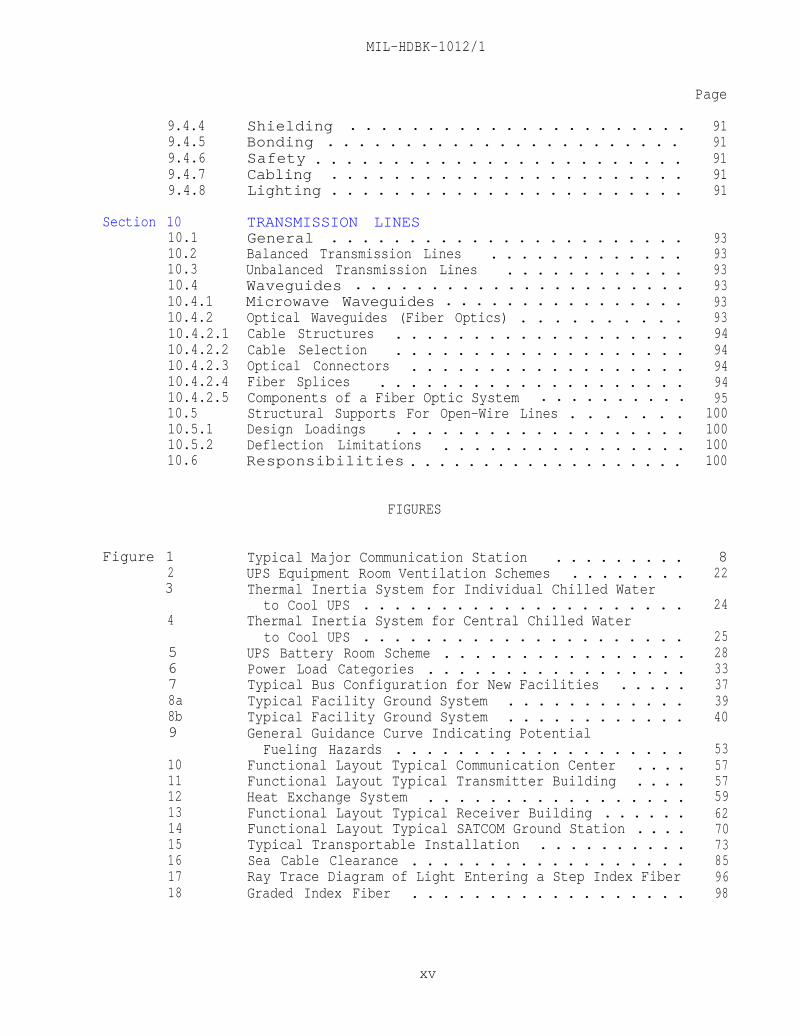
9.4.4 Shielding . . . . . . . . . . . . . . . . . . . . . . 919.4.5 Bonding . . . . . . . . . . . . . . . . . . . . . . . 919.4.6 Safety . . . . . . . . . . . . . . . . . . . . . . . . 919.4.7 Cabling . . . . . . . . . . . . . . . . . . . . . . . 919.4.8 Lighting . . . . . . . . . . . . . . . . . . . . . . . 91
Section 1010.110.210.310.410.4.110.4.210.4.2.110.4.2.210.4.2.310.4.2.410.4.2.510.510.5.110.5.210.6
Figure 123
4
5678a8b9
101112131415161718
TRANSMISSION LINESGeneral . . . . . . . . . . . . . . . . . . . . . . . 93Balanced Transmission Lines . . . . . . . . . . . . . 93Unbalanced Transmission Lines . . . . . . . . . . . . 93Waveguides . . . . . . . . . . . . . . . . . . . . . . 93Microwave Waveguides . . . . . . . . . . . . . . . . 93Optical Waveguides (Fiber Optics) . . . . . . . . . . 93Cable Structures . . . . . . . . . . . . . . . . . . . 94Cable Selection . . . . . . . . . . . . . . . . . . . 94Optical Connectors . . . . . . . . . . . . . . . . . . 94Fiber Splices . . . . . . . . . . . . . . . . . . . . 94Components of a Fiber Optic System . . . . . . . . . . 95Structural Supports For Open-Wire Lines . . . . . . . 100Design Loadings . . . . . . . . . . . . . . . . . . . 100Deflection Limitations . . . . . . . . . . . . . . . . 100Responsibilities . . . . . . . . . . . . . . . . . . . 100
FIGURES
Typical Major Communication Station . . . . . . . . . 8UPS Equipment Room Ventilation Schemes . . . . . . . . 22Thermal Inertia System for Individual Chilled Water
to Cool UPS . . . . . . . . . . . . . . . . . . . . . 24Thermal Inertia System for Central Chilled Water
to Cool UPS . . . . . . . . . . . . . . . . . . . . . 25UPS Battery Room Scheme . . . . . . . . . . . . . . . . 28Power Load Categories . . . . . . . . . . . . . . . . . 33Typical Bus Configuration for New Facilities . . . . . 37Typical Facility Ground System . . . . . . . . . . . . 39Typical Facility Ground System . . . . . . . . . . . . 40General Guidance Curve Indicating Potential
Fueling Hazards . . . . . . . . . . . . . . . . . . . 53Functional Layout Typical Communication Center . . . . 57Functional Layout Typical Transmitter Building . . . . 57Heat Exchange System . . . . . . . . . . . . . . . . . 59Functional Layout Typical Receiver Building . . . . . . 62Functional Layout Typical SATCOM Ground Station . . . . 70Typical Transportable Installation . . . . . . . . . . 73Sea Cable Clearance . . . . . . . . . . . . . . . . . . 85Ray Trace Diagram of Light Entering a Step Index Fiber 96Graded Index Fiber . . . . . . . . . . . . . . . . . . 98
xv
Table 1 Separations and Clearances . . . . . . . . . . . . . . . 42 Minimum Filter Performance . . . . . . . . . . . . . . 18
MIL-HDBK-1012/1
TABLES
Page
BIBLIOGRAPHY . . . . . . . . . . . . . . . . . . . . . . . . . . . . . 101
REFERENCES . . . . . . . . . . . . . . . . . . . . . . . . . . . . . . 105
xvi
MIL-HDBK-1012/1
Section 1: INTRODUCTION
1.1 Scope. This military handbook, MIL-HDBK-1012/1, establishescriteria for the design of electronic facilities.
1.2 Cancellation. This handbook, MIL-HDBK-1012/1, cancels andsupersedes DM-12.1, dated April 1983.
1.3 Responsibilities. The design of Navy electronic facilitiesrequires close coordination between the designer and other parties.Responsibilities involved in design stages are as follows:
1.3.1 Chief of Naval Onerations (CNO). The CNO is the Director of NavalCommunications, who sponsors and supports Naval communication facilities.through the Naval Telecommunications Command and other commands. The CNO, asthe user, states the needs of the operating and supporting facilities forresearch and development, improved equipment, new equipment, spare and repairparts, consumables, training, maintenance, personnel facilities, and any otherrequirements of the user. In many instances, the CNO is responsible forsupporting the Defense Communication Agency (DCA), which is the sponsor forthe nation's world-wide Defense Communications System (DCS).
1.3.2 Naval Facilities Engineering Command (NAVFAC). NAVFAC isresponsible for design, development, and construction of the facilitiesancillary to and/or required for the support or housing of electronicequipment and operating personnel. NAVFAC provides technical guidance anddirection in shore facility engineering from project inception to completion.
1.3.3 Space and Naval Warfare Systems Command (SPAWAR). SPAWAR exercisestechnical control of design, development, procurement, and installation of theelectronic equipment for an electronic facility at a shore activity. SPAWARprovides technical guidance and direction in shore electronic engineering fromproject inception to completion, except in special cases where the electronicsystems or equipment is specifically assigned to another command.
1.3.4 Maintenance Authority. SPAWAR exercises technical control throughregional and district offices, whose responsibilities include installation andmaintenance engineering of electronic equipment that is beyond the capacity ofstation forces. Regional and district offices represent SPAWAR for electronicengineering control while the architect-engineer develops the design.
1.3.5 Designer. The architect-engineer or equivalent Navy personnel(hereafter called "the designer") usually enters design development after theoperational requirement has been established and before actual constructionbegins. The designer plans the building to satisfy the operationalrequirements normally set forth in the Base Electronic System Engineering Plan(BESEP) (refer to paragraph 1.5.1) and prepares project drawings andspecifications under the control of NAVFAC and the guidance of SPAWAR.Requirements for military construction and special projects that do notdirectly involve electronic equipment, and thus do not require a BESEP, are

MIL-HDBK-1012/1
identified in project documentation, The designer must maintain close liaisonwith the NAVFAC command responsible for the particular project, which willcoordinate all technical matters with the sponsors and users of the project.
1.4 Policy. The design of electronic facilities should be based onoperational requirements. The primary consideration is that operationalcommunication buildings and other electronic facilities be sited, arranged,and constructed to provide the most effective communications possible.Whenever compromises between operational requirements and convenience, cost,or energy conservation become necessary, such compromises should be resolvedin favor of operational requirements. Where there is conflict between twomandatory Government documents, the more stringent requirement governs. Inall cases, the BESEP shall be the overriding document.
1.5 Principal Data Sources
1.5.1 BESEP. The basic document used by SPAWAR for planning andcontrolling shore station electronic installation work is the BESEP. Ittranslates operational requirements into a detailed technical plan for meetingthe requirements. It is prepared by representatives of SPAWAR, incollaboration with NAVFAC, and is approved by the sponsor for use in designdevelopment. A detailed description of the BESEP, as well as policy andprocedures for its use, is given in NAVELEXINST 11000.1, The Base ElectronicSystem Engineering Plan (BESEP): Policy and Procedures for Utilization of,dated 21 July 1971. The BESEP generally provides the following information:
1.5.1.1 General Requirements. The BESEP establishes the requirements ofthe project, the scope and layout of the planned facility, the design andinstallation of the electronic system, information on the electronic equipmentto be used, details of system checkout, and characteristics of the physicalplant.
1.5.1.2 Design Data. The BESEP includes information on structurallimitations; recommended locations of electronic equipment, power panelboards,special red or black panelboard designations, and special power requirements;identification of red areas; antenna locations and the number, type,performance, and frequency ranges required; cable types and terminationlocations; Radio-Frequency (RF) shielding requirements, other requirements forprecautions against radiation hazards, and characteristics of the source ofradiation; high-altitude electromagnetic (HEMP) pulse protection requirement;electronic equipment areas of concentrated heat load and requirements forspecial air conditioning or environmental control; recommended locations ofcompressed air outlets,systems;
specifying pressure and valve requirements; groundingand internal security. Requirements relevant to the specific site
and supporting facilities are also included. The completeness of suchinformation and the amount of detail furnished to the designer depend on thecircumstances of the project, and, in emergencies, may be brief and subject toaugmentation as the project progresses.
2
MIL-HDBK-1012/1
Section 2: SITE CONSIDERATIONS
2.1 Suitability of the Site. The primary consideration in selecting asite is its technical adequacy for meeting performance objectives. Generally,these objectives are maximum signal-to-noise ratios at the receivers andmaximum effective power radiated in the desired direction from thetransmitters. Although other factors enter into selection of a site,compromises for the sake of economy or logistic convenience must not interferewith performance. The principal considerations for technical adequacy areradio-frequency noise and topography, but suitability for construction atreasonable cost, link requirements between components of the communicationstation, land costs, and logistic support requirements are also considered.Other factors are availability of utilities, climate, foundation stability,survivability, physical security, and expansion potential.
2.2 Relationship to Design. The designer does not select the site, butthe considerations leading to its selection must be understood andincorporated in the design. Before the designer begins work, the FieldTechnical Authority of SPAWAR, in cooperation with the Engineering FieldDivision of NAVFAC, conducts a site selection survey and an ElectromagneticCompatibility (EMC) evaluation as part of the preparation of the BESEP.
2.2.1 Site Selection Survey. Considerations related to theelectromagnetic and physical environments that influence selection of a siteare listed in NAVELEX 0101,114, NAVELEX Calibration Program. A sample siteselection survey checklist is included in the appendix to that manual.
2.2.2 Electromagnetic Compatibility (EMC) Evaluation. Any factor thatprevents or degrades the reception of signals also degrades the ability of thesite to perform its mission. The receiving and direction-finding site shouldbe located where signal reception is known to be good. The EMC evaluation,described in NAVELEX 0101,106, Electromagnetic Compatibility andElectromagnetic Radiation Hazards, identifies environmental electromagneticinterference from all sources, as well as radio noise. The EMC evaluation isthe responsibility of SPAWAR. All pertinent information will be set forth inthe BESEP.
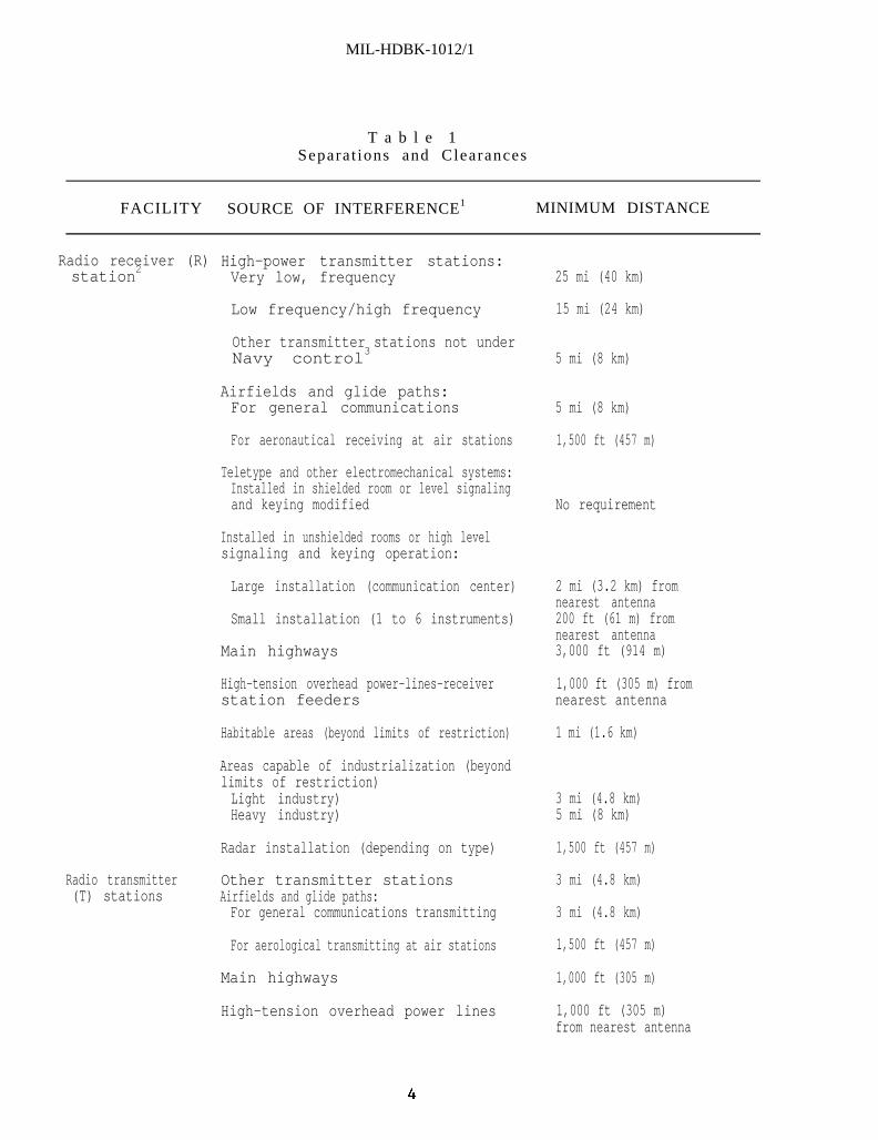
2.3 Isolation. Optimum radio communications depend largely onisolation of the site from sources of interference and on proper dispersion ofstructures within the site, Minimum separation distances for electromagneticinterference protection of receiver sites are given in NAVELEX 0101,102, NavalCommunications Station Design, and in Table 1. Special separationrequirements for Naval Security Group (NAVSECGRU) receivers are given inNAVELEX 0101,108, Naval Security Group Elements, Design and Performance.Specific requirements for each project are developed in the BESEP; variationsrequired by local conditions are also established by the BESEP or byauthorized changes to it.
3
MIL-HDBK-1012/1
T a b l e 1Separa t ions and Clearances
FACILITY SOURCE OF INTERFERENCE1 MINIMUM DISTANCE
Radio receiver (R)station2
High-power transmitter stations:Very low, frequency 25 mi (40 km)
Low frequency/high frequency 15 mi (24 km)
Other transmitter stations not underNavy control3 5 mi (8 km)
Airfields and glide paths:For general communications 5 mi (8 km)
For aeronautical receiving at air stations 1,500 ft (457 m)
Teletype and other electromechanical systems:Installed in shielded room or level signalingand keying modified No requirement
Installed in unshielded rooms or high levelsignaling and keying operation:
Large installation (communication center)
Small installation (1 to 6 instruments)
Main highways
2 mi (3.2 km) fromnearest antenna200 ft (61 m) fromnearest antenna3,000 ft (914 m)
High-tension overhead power-lines-receiverstation feeders
1,000 ft (305 m) fromnearest antenna
Habitable areas (beyond limits of restriction) 1 mi (1.6 km)
Areas capable of industrialization (beyondlimits of restriction)Light industry)Heavy industry)
3 mi (4.8 km)5 mi (8 km)
Radio transmitter(T) stations
Radar installation (depending on type)
Other transmitter stationsAirfields and glide paths:For general communications transmitting
For aerological transmitting at air stations
Main highways
1,500 ft (457 m)
3 mi (4.8 km)
3 mi (4.8 km)
1,500 ft (457 m)
1,000 ft (305 m)
High-tension overhead power lines 1,000 ft (305 m)from nearest antenna
MIL-HDBK-1012/l
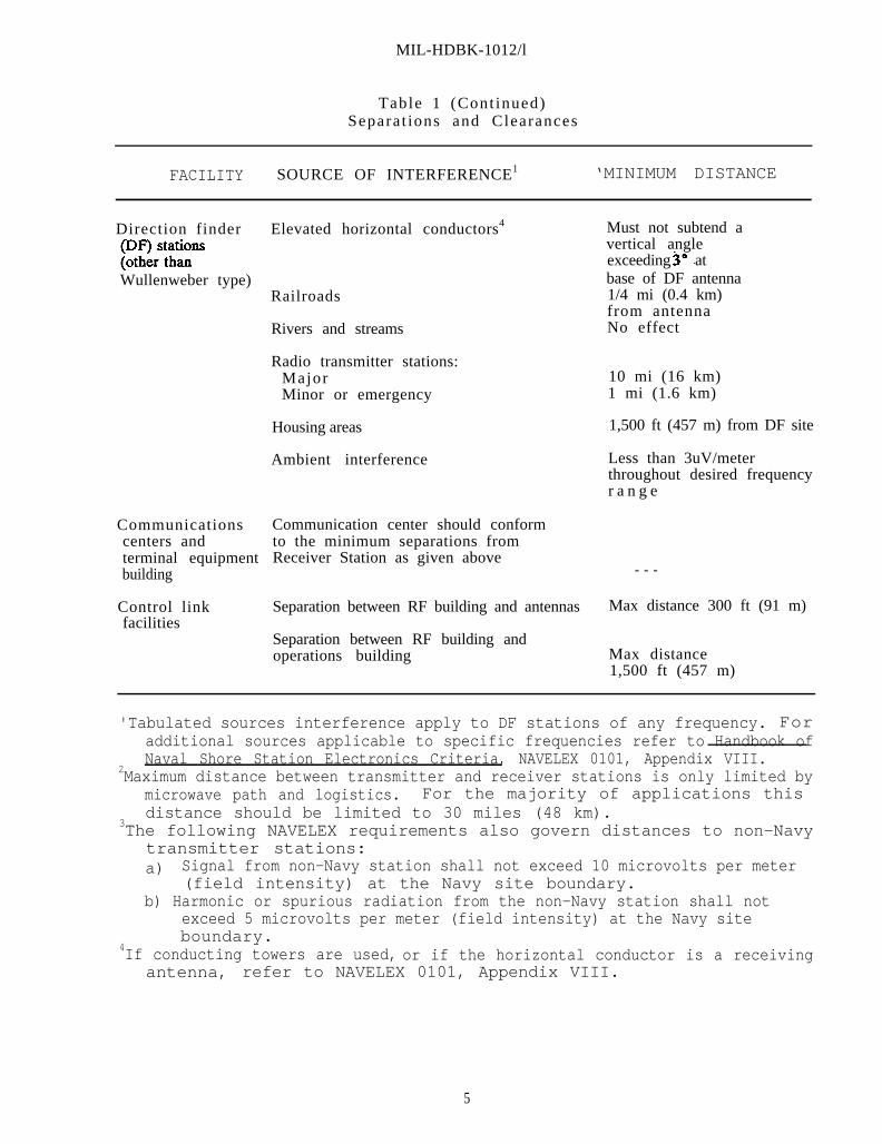
Table 1 (Cont inued)Separa t ions and Clearances
FACILITY SOURCE OF INTERFERENCE1 ‘MINIMUM DISTANCE
Direction finder Elevated horizontal conductors4
Wullenweber type)Railroads
Communicationscenters andterminal equipmentbuilding
Control linkfacilities
Rivers and streams
Radio transmitter stations:MajorMinor or emergency
Housing areas
Ambient interference
Communication center should conformto the minimum separations fromReceiver Station as given above
Separation between RF building and antennas
Separation between RF building andoperations building
Must not subtend avertical angleexceeding atbase of DF antenna1/4 mi (0.4 km)from antennaNo effect
10 mi (16 km)1 mi (1.6 km)
1,500 ft (457 m) from DF site
Less than 3uV/meterthroughout desired frequencyr a n g e
- - -
Max distance 300 ft (91 m)
Max distance1,500 ft (457 m)
'Tabulated sources interference apply to DF stations of any frequency. Foradditional sources applicable to specific frequencies refer to Handbook ofNaval Shore Station Electronics Criteria, NAVELEX 0101, Appendix VIII.
2Maximum distance between transmitter and receiver stations is only limited bymicrowave path and logistics. For the majority of applications thisdistance should be limited to 30 miles (48 km).
3The following NAVELEX requirements also govern distances to non-Navytransmitter stations:a) Signal from non-Navy station shall not exceed 10 microvolts per meter
(field intensity) at the Navy site boundary.b) Harmonic or spurious radiation from the non-Navy station shall not
exceed 5 microvolts per meter (field intensity) at the Navy siteboundary.
4If conducting towers are used, or if the horizontal conductor is a receivingantenna, refer to NAVELEX 0101, Appendix VIII.
5

MIL-HDBK-1012/1
2.3.1 Buffer Zones. Requirements for buffer zones, which protect thesite and adjoining communities from man-made radio noise, are described inNAVELEX 0101,102, Radio Communications Station Design. Registry of this landunder local or state laws that restrict further development of radiation-sensitive areas is the most desirable means of protecting the site.
2.3.2 Other Considerations. Because of electromagnetic hazards orsecurity considerations, it may be desirable to isolate buildings fromcommunity facilities, population centers, and public transportation lines. Ifhazardous conditions are absent, however, proximity to transportation and tocommunity recreation facilities can be desirable.
2.4 Expansion. Provide for future expansion as required by the BESEP.If there are no specific requirements, plan for expansion as a matter ofcourse. Locate support facilities near the boundary of the station to permitexpansion without undue invasion of the antenna area. When the budgetpermits, construction of separate structures or self-contained elements ispreferred to expansion by extension of existing facilities.
2.5 Siting Procedure. Developing the optimum site configurationrequires coordination of civil engineering and electronic engineering. Thedesigner will be provided with preliminary site layouts developed by theelectronic system engineering activity. These documents show the site'sdimensions, schematic building layout, utility requirements, access roadlayout, direction and number of transmission paths, size and layout ofsupporting structures, and special design considerations for optimumperformance of the electronic system.
2.6 Site Plan Components. Using the preliminary site layout preparedby the electronic system engineering activity, information from the sitesurvey, and the criteria herein, the designer shall prepare a final site plan.In addition to the location of facility components, the final plan shall showthe site boundary and property lines; the base line and bench marks; accessroads and parking areas; elevation, azimuth, and coordinates for the center ofeach antenna; underground utilities; underground services; and existingbuildings and facilities. In general, electronic facilities (structures) aresimilar to other Navy shore facilities, and the criteria in the NAVFAC designmanuals are applicable. Characteristics of specific electronic buildings andsite components are discussed in Section 8. Special considerations forphysical security and personnel safety are discussed in Sections 6 and 7.Site development criteria unique to shore electronic facilities are discussedbelow.
2.7 Survey Base Line. The construction base line normally isestablished by the siting survey performed by the electronic systemengineering activity. Special precautions are required to protect the baseline markers from movement or loss during construction.
2.8 Layout. The general location of buildings is established on thegeneral development map of an activity. Technical details bearing on thelocation and orientation of buildings are given in the BESEP and furnished tothe designer for adaptation to the site. The arrangement of facilities at acommunication station varies according to mission. The functions of each
6
MIL-HDBK-1012/1
facility, as discussed in Section 8, should be considered in planning thelayout. Detailed siting criteria for specific electronics facilities may befound in the appropriate Naval Shore Electronics Criteria Manual, 0101 Series. Antenna spacing and siting, which usually receive first consideration, arediscussed in NAVELEX 0101,104, HF Radio Antenna Systems; the locations ofbuildings are determined in relation to the antenna locations.
Operating buildings, such as transmitter and receiver buildings,and the terminal point of transmission lines should be as near the center ofthe station or antenna field as possible. Support buildings should be nearthe station boundary. Where radio interference is a problem, locate roads andparking areas so that traffic will not interfere with reception at receiverstations. Insofar as operating and security requirements permit, buildingsshould be oriented to provide maximum economy in heating and cooling and tokeep paving to a minimum. Figure 1 is a schematic representation of a typicalmajor communication station system.
2.9 Site Security Considerations. Facility layouts must be compatiblewith an overall installation security plan and must consider the location ofguard posts, patrols, and security response forces; the location andcharacteristics of intrusion detection systems; facility access control; andnatural factors. Security factors that influence exterior layouts arediscussed in MIL-HDBK-1013/1, Design Guide Lines for Physical Security ofFixed Land-Based Facilities. Security at electronic facilities is discussedin greater detail in Section 6.
2.10 Surface and Subsurface Drainage. The requirements of NAVFAC DM-5.03, Drainage Systems, shall apply, except as follows:
2.10.1 Runoff. Calculation of storm water runoff shall be based on astorm with a 50-year design frequency.
2.10.2 Pipes. Metallic pipe and reinforced concrete pipe areinappropriate at some sites. Their use will be determined by projectrequirements.
2.10.3 Drainage. Swale drainage shall be used to the greatest extentpossible. Minimal design velocities shall be maintained to avoid damage ofground planes.
2.10.4 Exceptions. Storm drain pipe shall not be used through an antennaground plane.
2.11 Paved Areas. The requirements of NAVFAC DM-5.5, General Provisionsand Geometric Design for Roads, Streets, Walks, and Open Storage Areas, shallgovern, except as follows:
2.11.1 Traffic Areas. Parking areas, pedestrian walks, and other trafficareas adjacent to buildings shall be surfaced with bituminous concrete orportland cement concrete.
2.11.2 Roads. Access roads shall be all-weather roads, with surfacecourses adequate for design traffic loads.
7

Figure 1Typical Major Communication Station.
MIL-HDBK-1012/1
2.11.3 Curbs. Curb and gutter normally are not provided.
2.11.4 Guardrails. Guardrail shall be provided where required forpersonnel safety or for protection of equipment. The requirements of OSHAStandard 29 CFR 1910.23, Standards for General Industry, shall apply.
2.12 Water Supply and Wastewater Disposal. The requirements of NAVFACMIL-HDBK-1005/7, Water Supply Systems, and MIL-HDBK-1005/8, DomesticWastewater Control, shall apply, except as follows:
2.12.1 Water Supply. Hauling water is not an acceptable means ofsupplying water to a permanent electronic facility site.
2.12.2 Pipe. Where metallic pipe and reinforced concrete pipe areinappropriate at a particular site, this will be indicated in the projectBESEP.
2.12.3 Lawn Irrigation. Lawn irrigation normally is not provided.
2.12.4 Fire Protection. In electronic facilities of noncombustibleconstruction, water demands and hydrant spacing for external fire protectionshall be determined in accordance with the requirements of MIL-HDBK-1008, Fire Protection Engineering, for unsprinklered facilities under light-hazard,favorable conditions. For combustible construction, other guidelines in MIL-HDBK-1008 shall apply.
2.12.5 Conformance to Regulations. Water supply and wastewater disposalsystems shall conform to applicable local, state, and federal requirements andregulations.
2.13 Landscaping and Ground Cover. The requirements of MIL-HDBK-1013/1shall apply, except as follows:
2.13.1 Placement. Landscaping and ground cover shall be provided only tothe extent that they reduce site maintenance. Vegetation shall not interferewith antennas and ground mats. Some site areas must be kept free ofvegetation; the designer shall consult the electronic system engineeringactivity for this information.
2.13.2 Fire Breaks. Where buildings are of combustible construction, firebreaks shall be provided in accordance with MIL-HDBK-1008. Fire breakrequirements within the antenna field shall be based on the specific exposurehazards.
2.14 Fencing, Gates, and Guard Towers. The requirements of DM-5.12,Fencing. Gates, and Guard Towers, shall govern, except as specified otherwisein Section 6 of this handbook.

MIL-HDBK-1012/1
THIS PAGE INTENTIONALLY LEFT BLANK
10

MIL-HDBK-1012/1
Section 3: ARCHITECTURAL AND STRUCTURAL ENGINEERING
3.1 Basic Construction Criteria
3.1.1 General Requirements. Permanent communication buildings shall bewindowless structures of masonry and/or concrete providing open space free ofcolumns and similar obstructions. Buildings housing electronic equipmentshall be of noncombustible construction. Where practicable, operating spacesshould be designed for resistance to blast, earthquakes, hurricanes, andtyphoons. In overseas locations, locally available materials and methodsshall be used wherever possible.
3.1.2 Equipment Spaces. Emergency generators should be located inseparate buildings, although they may be located within the operationsbuilding if they are properly isolated from the rest of the structure in termsof fire protection, sound attenuation, and vibration control. Battery rooms,consisting of cells mounted on manufacturer-supplied battery racks, arenormally adjacent to the uninterruptible power supply equipment room. Thebattery room should be windowless, adequately ventilated to prevent explosiveconcentrations of hydrogen gas, reasonably well insulated against thermal heatloss and heat gain, and located to minimize solar heat gain.
Frequency conversion equipment should be as close as possible tothe equipment it serves. Motor generators should be located in a separateroom to reduce noise levels and heat gains in operating spaces. Staticconverters may be located in the equipment space or operating space, becausethey produce minimal heat and noise. Operating spaces containing electronicequipment usually require close temperature and humidity control. Vaporbarriers beneath floor slabs and incorporated into roofing are usuallysufficient to prevent moisture migration into and out of interior electronicequipment spaces. Additional protection must be provided where exterior wallsform part of the equipment space.
3.1.3 Special Requirements. Special requirements, such as specialfinishes, gaskets, or thermally isolated glazing, will be specified by theBESEP. In some facilities, special equipment and operating characteristics mayrequire that the wall be constructed of nonferrous and nonmagnetic materials.This requirement will be stated in the BESEP. Bonding and grounding forcontrol of compromising emanations shall be in accordance with NACSIM 5203,Guidelines for Facility Design and Red/Black Installations. Shieldedenclosures shall conform to the requirements of NAVFAC NFGS-13093, RadioFrequency Shielded Enclosures. Demountable Type, and NFGS-13094, RadioFrequency Shielded Enclosures. Welded Type. Shielding, as specified in theBESEP, shall be incorporated into the design of the structure, and itsinstallation shall be scheduled at a time in the construction phase when itcan be done most economically.
3.2 Structural Design
3.2.1 Foundations. Foundations design shall conform to the criteria inNAVFAC DM-7.02, Foundations and Earth Structures.
11
MIL-HDBK-1012/1
3.2.2 Framing. Structural framing shall conform to the criteria inNAVFAC DM-2 series Structural Engineering. Roof framing shall be designed tosupport all roof-mounted equipment.
3.3 Exterior Walls. Unless otherwise specified, walls shall be masonryunits, or, for certain buildings, precast or cast-in-place concrete. Wallconstruction shall be consistent with the requirements of NAVFAC DM-1.01,Basic Architectural Requirements & Design Considerations.
3.4 Interior Walls
3.4.1 Permanent Partitions. Interior partitions for stairwells, vaults,elevator hoistways, toilets, and other areas requiring fixed partitions shallbe masonry units or concrete. Partitions in storage areas shall be ofconcrete masonry.
3.4.2 Nonpermanent Partitions. Interior partitions in electronicoperating spaces shall be nonload-bearing and removable. Electrical power andcontrol wiring shall not be located in these partitions. Permanent partitionsseparating electronic operating spaces from other spaces shall be fire ratedand constructed in accordance with National Fire Protection Agency (NFPA) 75,Computer/Data Processing Equipment. All partitions using metal framing and/orsurfacing shall be suitably bonded and grounded, if required by SPAWAR.
3.5 Floors
3.5.1 Permanent Floors. Selection of floor construction should take intoconsideration the placement of cables and wiring for electronic equipment. Anequipotential plane conforming to MIL-HDBK-419, Volume 1, Grounding. Bonding,and Shielding for Electronic Equipment and Facilities, Basic Theory,and Volume 2, Grounding, Bonding, and Shielding for Electronic Equipment andFacilities Applications, shall be installed in the floor of all spaces. Thepreferred method of placing cables and wiring is given in the BESEP for thefacility.
3.5.2 Raised Floors. When raised flooring is required, it shall conformto the requirements of NFPA 75, MIL-F-29046, Flooring, Raised: GeneralSpecifications for, and MIL-HDBK-1008. The flooring system shall be either abolted grid (stringer) or a rigid grid system, as required by the BESEP.Finishes shall be seamless vinyl or laminated plastic. All air supply panelsand similar inserts shall be flush with the flooring surface. Installationshall conform to MIL-HDBK-419, Volumes 1 and 2. A raised floor installationover a level permanent floor is generally preferable for flexibility of cableaccess and routing; however, depending on the facility layout, a dropped orrecessed permanent floor may be used.
3.6 Roofs. Roofs shall be constructed of noncombustible materials.Where HEMP pulse requirements must be considered, metal roof deck ispreferred; elsewhere, precast or cast-in-place concrete is preferred. Allroof construction shall conform to the requirements of MIL-HDBK-1190, FacilityPlanning and Design Guide, and MIL-HDBK-1008.
12

MIL-HDBK-1012/1
3.7 Ceilings. Ceiling design shall be consistent with requirements forlighting, air conditioning, ventilation, cable tray layout, acousticaltreatment, and fire protection, as specified in the BESEP. Where raised floors are used, 8 feet (2.44 meters(m)) is the minimum clear height above theraised floor, and 10 feet (3.05 m) is preferred. In uninterruptible powersupply, transmitter, and similar equipment spaces where heat dissipation is adesign factor, a clear height of more than 10 feet (3.05 m) may be required.
3.8 Finishes. Flame spread and smoke developed ratings for interiorfinishes shall conform to MIL-HDBK-1008.
3.8.1 Operating Areas Housing Electronic Equipment. Floors shall be 1/8-inch vinyl tile with a vinyl or rubber tile base. Walls shall be acousticpanels. Ceilings in operational electronic spaces shall also be acousticpanels.
3.8.2 Storage Spaces, Vaults, and Mechanical Equipment Rooms. Floorsshall be concrete with a dusted-on finish with hardener; floor hardener mustbe used on all concrete floors in buildings housing electronic equipment. Ingeneral, bases should not be used. Where required for protection of wallfinishes or for sanitation, however, vinyl or rubber bases shall be used.Walls shall be exposed. Ceilings shall be of exposed concrete ornoncombustible, suspended construction.
3.8.3 Offices, Corridors, and Toilets. Finishes shall be as specified inMIL-HDBK-1001/2, Materials and Building Components.
3.8.4 Other Spaces. In uninterruptible power supply spaces and emergencygenerator rooms, floors shall be concrete with a dusted-on finish withhardener. Bases shall not be used. In battery rooms, floors and bases shallhave an acid-resistant finish. Walls and ceilings shall be exposed.
13
MIL-HDBK-1012/1
Section 4: MECHANICAL ENGINEERING
4.1 General. All mechanical criteria that apply to naval facilities ingeneral also apply to electronic facilities. Only items specificallyapplicable to electronic facilities are covered in this section.
4.2 Heating, Ventilating, and Air Conditioning (HVAC) Systems
4.2.1 Outside Design Conditions
4.2.1.1 Permanent and Transportable/Nonrelocatable Facilities. NAVFAC P-89, Engineering Weather Data,shall be used to determine winter and summeroutdoor design conditions. HVAC systems for spaces designated as critical bythe BESEP shall be designed on the basis of the 99 percent column for heatingand the 1 percent dry-bulb and mean coincident wet-bulb columns forventilating and air conditioning. Design of systems for other spaces shall bebased on the 97.5 percent and 2.5 percent columns, respectively.
4.2.1.2 Transportable/Tactical and Transportable/Relocatable Facilities.If the location of the installation is known and it is probable that thelocation will not change, the outdoor design conditions defined above shall beused. If the location is not known, or if it is probable that the containerwill be relocated, HVAC equipment shall be designed for the "worst case"likely to be encountered. Temperature and humidity extremes are defined inMIL-STD-210, Climatic Extremes for Military Equipment.
4.2.2 Inside Design Conditions. Spaces not containing electronicequipment but meeting the programming priority requirements of MIL-HDBK-1190shall be air conditioned. Inside design conditions shall be in accordancewith NAVFAC DM-3.03, Heating, Ventilating, Air Conditioning andDehumidification Systems. Spaces not meeting the priority requirements shallbe heated and ventilated only, also in accordance with NAVFAC DM-3.03.Requirements for electronic equipment spaces are discussed below. In allcases, the BESEP should be consulted for specific guidance.
4.2.2.1 Computer Rooms. These areas generally should be maintained at72 2 degrees Fahrenheit (F) (22 1 degrees Celsius (C)), 45 5 percentrelative humidity (RH) year-round. If a wider range in space conditions canbe tolerated by the equipment, the less restrictive values should be used.
4.2.2.2 Receiver Buildings and Similar Areas. Electronic equipment inreceiver buildings, telephone and switchgear rooms, radio direction-finderfacilities, and similar areas generally require a year-round environment of 75 5 degrees F (24 2 degrees C), 50 5 percent RH.
4.2.2.3 Transmitter Buildings. Depending on the type of system utilized toremove waste heat from the facility (see Section 8), the following conditionsapply:
a) Ventilated spaces, such as plenums, 90 degrees F (32 degrees C)minimum, 5 degrees F (3 degrees C) over ambient maximum and relative humidityas naturally occurs with the related ventilation.
14

MIL-HDBK-1012/1
b) Air conditioned spaces, such as operating corridors and controlrooms, 80 +/- 5 degrees F (27 +/- 2 degrees C) and 50 +/- 10 percent relativehumidity.
c) Heat exchange/air conditioned spaces, such as transmitter roomsthat are not partitioned into separate corridors and plenums, 70 degrees F (21degrees C) minimum and 90 degrees F (32 degrees C) maximum with 60 percentmaximum relative humidity. Such facilities may have, but are not required tohave separately enclosed control rooms conditioned as in para. 4.2.2.3 b,above.
4.2.2.4 Uninterruptible Power Supply (UPS) Equipment Rooms. Depending onthe type of system utilized to remove waste heat from the room (refer toSection 8), the following conditions apply:
a) Ventilated equipment rooms are controlled to the sametemperature conditions as in para. 4.2.2.3 a, above, for ventilatedtransmitter spaces.
b) Heat exchange/ventilation (similar to para. 4.2.2.3 c, above),except using ventilation as the auxiliary heat removal means (in lieu of airconditioning) can also be used, in which case the environmental limits shouldbe 70 degrees F (21 degrees C) minimum, 5 degrees F (2 degrees C) over ambientmaximum with relative humidity as naturally occurs with this system.
c) Air conditioning 80 +/- 5 degrees F (27 +/- 2 degrees C) and 50 +/-10 percent relative humidity during normal operation with conditions risingbut not exceeding 120 degrees F (49 degrees C) and relative humidity as willoccur during a 15 minute power outage. Note that this will require a thermalinertia system in most installations.
d) For the systems described in paras. 4.2.2.4 a, b, and c, ifother heating is not available, a unit heater shall be installed in theequipment room to provide heating when the UPS is off for extended maintenanceperiods (no waste heat available) and to prevent condensation damage. Forthese occasions the heater shall maintain, and the controlling thermostatshall be set for, a temperature of 85 degrees F (29 degrees C). Unit to beenergized only when the UPS is off to avoid cross control.
4.2.2.5 UPS and Microwave Equipment Battery Rooms. These rooms shall beventilated at all times. During cold weather, sufficient heat shall beprovided to remain within the following limits:
a) Temperature - 65 degrees F (18 degrees C) minimum, winter onlyfrom waste heat, and a maximum as naturally occurs with ventilation.
b) Humidity - No minimum and 90 percent maximum. See para.4.2.2.4 d) for method to limit.
c) A unit heater shall be installed in the battery room to provideheat when waste heat is not available, to augment waste heat if inadequate andto prevent condensation. The heater shall maintain, and the controllingthermostat shall be set for 60 degrees F (16 degrees C). This heater shall be
15

MIL-HDBK-1012/1
be energized during winter only via a summer/winter switch in series with thecontrol thermostat. Humidity shall be limited to 90 percent by energizing theunit heater at any time without the limitation of the summer/winter switch butwith the limitation of a differential temperature limit thermostat set for 5degrees F (3 degrees C) over the outside ambient temperature.
4.2.2.6 Emergency Generator Rooms. Refer NAVFAC DM-3 Series MechanicalEngineering, for interior design requirements.
4.2.2.7 Transportables. Inside conditions for transportables are the sameas for permanent facilities depending on the needs of the equipment therein asoutlined in the BESEP. This includes temperature limits and humidity highlimit. Humidification is normally not provided unless a water supply isavailable.
4.2.3 Guidelines for HVAC System Design. In addition to the specificrequirements in the BESEP, the following guidelines apply to all projects.
4.2.3.1 Simplicity. Naval electronic facilities are located worldwide,often in harsh environments. In many locations maintenance is a problembecause of the lack of skilled labor and the difficulty in obtaining spareparts. Systems that are straightforward in concept and design are preferredto complicated systems that are difficult to operate and maintain.
4.2.3.2 Equipment Selection. NAVFAC DM-3.03 provides informationapplicable to a variety of system designs. The following should be notedhowever:
a) Sensible-to-total-heat ratios. Electronic facilities differgreatly from comfort cooling applications. The cooling load in electronicequipment spaces is predominantly sensible; sensible-to-total-heat ratiosapproaching one are common. Cooling coils designed for comfort applicationsare inappropriate since they excessively dehumidify equipment spaces tosatisfy the sensible load. Conversely, air handlers serving electronicequipment spaces should not serve comfort-cooled areas as well, since they maynot satisfy the latent load in those areas.
b) Fan-coil units. NAVFAC DM-3.03 notes that fan-coil unitsshould not be used for comfort cooling in humid climate zones. Properlydesigned, however, they are suitable for electronic equipment spaces. Vaporbarrier protection should be adequate and outside ventilation air should beminimized.
c) Economizer cycle. NAVFAC DM-3.03 restricts the use ofeconomizer cycle controls, mainly in relation to the economics of operation.For electronic equipment areas, however, economizer cycles make precisecontrol of humidity difficult. For those applications where no backup coolingis provided, an economizer cycle does offer a valid means of emergencycooling, even in warm climates, if no other means are available.
4.2.3.3 Fuel Selection. In electronic facilities, cooling or waste heatremoval is the predominant mode of operation and heating requirements may benonexistent or minimal. For those applications where additional heating is
16
MIL-HDBK-1012/1
needed on an occasional basis only, when equipment is off or when unseasonableweather exists, electric resistance heating should be considered because ofits low first cost, low maintenance, simplicity, and reliability. If a fuelselection analysis is prepared for areas not containing electronic equipment, life-cycle costing techniques should be in accordance with NAVFAC P-442,Economic Analysis Handbook.
4.2.3.4 Humidification. Electronic equipment areas generally require lesshumidification per thousand BTU per hour (MBH) of heating than comfortapplications. Humidification needs are higher if a proper vapor barrier isnot provided, if excessive fresh air is admitted to the space, ifdehumidification during the cooling process is excessive, or if the humidityratio of the outside ventilation air is less than the humidity ratio desired.The following methods of humidification are suitable:
a) Steam grid. This method is the simplest and provides thequickest response. It is preferred when steam (devoid of chemicals) isavailable. This process will add to the cooling load.
b) Atomized water. Atomized water provided by air-assist,mechanical, or water spray methods provides fast response and reduces thecooling load. It requires in-line demineralizers to avoid mineral dust in theair, however, this can be expensive if the water is high in mineral content(hard) or if large quantities of outside ventilating air are admitted.
c) Evaporative. Humidification, by pan-type humidifiers, gives aslow response, possible overshoot and may add to the cooling load.Maintenance requirements are high in areas with hard water although anautomatic flush cycle helps to reduce maintenance.
d) Steam injection. Steam injection by electric package unitsprovides medium to fast response, requires large amounts of electrical powerand adds to the cooling load. Scaling problems are the same as with theevaporative pan method.
4.2.3.5 Dehumidification. Electronic equipment areas also require lessdehumidification per ton of cooling than comfort applications. Lessdehumidification is required in properly designed electronic facilities.Cooling coils, therefore, should be designed for higher sensible-to-total loadratios. Occasional higher latent loads can be handled by small separatedehumidifiers located in the space and controlled by a humidistat ifnecessary. Reheat should be avoided where possible and, if required, shouldutilize waste heat.
4.2.3.6 Air Distribution. Where floors are raised, underfloor distributionof conditioned supply air is convenient. Unless the equipment is specificallydesigned to receive raw supply air, direct connection between the air plenumand the equipment should be avoided. Instead, relocatable floor panels shouldsupply air to the room and the equipment should take tempered air from theroom. If overhead distribution is provided, low-velocity/low-pressure duct-work is desirable. Both with overhead and underfloor air distribution, airterminal devices must be located to allow the air to reach the area of theloads. If the electronic equipment is in a high-bay area with an overhead
17
MIL-HDBK-1012/1
cable grid network, and if the outlets are located above the network, the airmay tend to short circuit. When the cable is under the floor, poor airdistribution may also occur due to cables or cable troughs blocking thelimited under floor space. Extending the supply or return ducts to floorlevel at columns and walls should be considered in high-load or congestedareas.
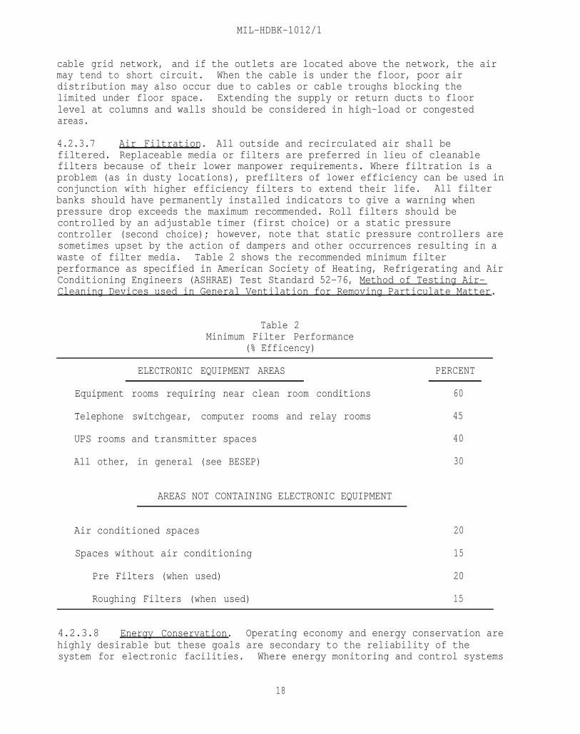
4.2.3.7 Air Filtration. All outside and recirculated air shall befiltered. Replaceable media or filters are preferred in lieu of cleanablefilters because of their lower manpower requirements. Where filtration is aproblem (as in dusty locations), prefilters of lower efficiency can be used inconjunction with higher efficiency filters to extend their life. All filterbanks should have permanently installed indicators to give a warning whenpressure drop exceeds the maximum recommended. Roll filters should becontrolled by an adjustable timer (first choice) or a static pressurecontroller (second choice); however, note that static pressure controllers aresometimes upset by the action of dampers and other occurrences resulting in awaste of filter media. Table 2 shows the recommended minimum filterperformance as specified in American Society of Heating, Refrigerating and AirConditioning Engineers (ASHRAE) Test Standard 52-76, Method of Testing Air-Cleaning Devices used in General Ventilation for Removing Particulate Matter.
Table 2Minimum Filter Performance
(% Efficency)
ELECTRONIC EQUIPMENT AREAS
Equipment rooms requiring near clean room conditions
Telephone switchgear, computer rooms and relay rooms
UPS rooms and transmitter spaces
All other, in general (see BESEP)
AREAS NOT CONTAINING ELECTRONIC EQUIPMENT
Air conditioned spaces
Spaces without air conditioning
Pre Filters (when used)
Roughing Filters (when used)
PERCENT
60
45
40
30
20
15
20
15
4.2.3.8 Energy Conservation. Operating economy and energy conservation arehighly desirable but these goals are secondary to the reliability of thesystem for electronic facilities. Where energy monitoring and control systems
18
MIL-HDBK-1012/1
are already in existence or are scheduled for installation, consider their usefor monitoring only (not control) to insure the HVAC system is not increasedat the expense of reliability. Use the following guidelines.
a) Base minimum outside ventilation air flow rate for airconditioned areas on average expected building occupancy rather than on asimple percentage of total air circulated. Where occupancy will varyconsiderably, an or CO2 sensor system to control the outside fresh airdamper should be considered for keeping outside air ventilation rates at theminimum required level.
b) Avoid conflict between components within the systems, such asexcessive latent cooling that must be offset with humidification duringtemperature control or excessive sensible cooling that must be offset withreheat during humidity control. System designs that properly match thesensible-to-total load ratio performance of the equipment to that of theapplication are necessary.
c) Avoid conflict or cross-control between units when multipleunits are used, as in computer rooms with multiple units.
d) Use capacity increments for improved part-load performance.
e) Features such as economizer cycles (except when provided andused only as emergency ventilation), night setback and wide-throttling-rangeor dual-setpoint thermostats are incompatible with electronic equipment spacesthat require close control.
f) For areas not containing electronic equipment, use properzoning to permit economizers, night setback and other energy conservationoptions.
g) Use simple but adequate controls. Electric controls are morethan adequate for most applications and are simple to understand and easy tomaintain by station forces. Electronic controls are more complicated andsometimes subject to error due to the proximity of heavy currents or RFinterference. Although the trend is toward more sophisticated electronic typecontrols, consideration should be given to the fact that outside contractmaintenance would probably be needed to maintain them. Pneumatic controlsrequire a compressor, dehydrator and space for same in the mechanical room.Unless constant and proper maintenance is given this type system it may becomecontaminated with moisture and will be erratic in operation thereafter. Thistype system is not recommended.
4.2.4 Applications. For spaces not containing electronic equipment, therequirements of NAVFAC DM-3.03 shall apply. Requirements for specificelectronic facilities are described in Section 8. Requirements which apply tomore than one facility type are described herein.
4.2.4.1 Computer Rooms and Spaces with Similar Equipment. Specificrequirements for computer rooms, receiver rooms, telephone and switchgearrooms, and electronic equipment maintenance shops will be indicated in the
19
MIL-HDBK-1012/1
BESEP. If the manufacturer's recommended conditions differ from thosespecified by this manual or the BESEP, the matter should be referred to SPAWARand NAVFAC for resolution.
a) Specialized equipment. HVAC units specifically designed forcomputer rooms and similar cooling applications are sometimes referred to asprocess coolers. They generally differ from units designed for comfortcooling, in that the cooling coils are designed for a much higher sensible-to-total cooling ratio; discharge air relative humidity may be limited to about80 percent, as opposed to nearly 100 percent in comfort cooling applications;and the cubic feet per minute (CFM)-per-ton value may be as high as 600 to800, as opposed to 400 for comfort cooling. These units are designed foryear-round use rather than the 1000 to 3000 hours of operation of comfort airconditioners. Both in-room equipment and central systems must be tailored tothe needs of the spaces served. This includes providing the proper degree ofair filtration, adequate humidification capability, the ability to providecooling in cold weather, and the proper type of cooling coils.
b) System types. HVAC equipment for electronic equipment/computerroom areas may be of the following types:
(1) Direct expansion, glycol- orwater-cooled;
(2) Direct expansion, air-cooled;
(3) Central chilled water system with in-room air units;
(4) Central chilled water system with central air handlers;
(5) Process chillers (for direct water-cooled computerequipment).
Advantages and disadvantages are discussed in the ASHRAE Handbook Series andin Section 8 of this manual. In general, systems with glycol are quitepopular due to the simplicity of installation and ease in maintaining winteroperation. However, it should be noted that these type systems are the leastefficient of all systems when evaluated on a BTU/watt power use basis.
c) Provisions for standby. The preferred approach is to dividethe total required capacity into increments of reasonable size and thenprovide one or more extra increments/units for backup. With central systems,consider configuring piping and ductwork to allow systems serving noncriticalareas to serve critical areas in an emergency. On the water side, multiplechillers, pumps and cooling tower cells should be provided where applicable.Consult the BESEP for guidance in regard to areas requiring backup HVACequipment.
d) Auxiliary equipment. Areas requiring close temperature andhumidity control year-round shall be provided with 7-day temperature andrelative humidity recorders. Alarms should indicate out-of-tolerance roomtemperature and relative humidity and appropriate HVAC equipment off-line oroff-normal conditions.
20
MIL-HDBK-1012/1
4.2.4.2 UPS Equipment Rooms. Figure 2 shows several approaches for theenvironmental control of these areas. These methods are also applicable fortransmitter buildings, except that transmitter buildings do not require backupheating and ventilation.
a) Fans. Provide two fans capable of handling the amount of airexhausted through the equipment cabinet plus about ten percent for good sweepat the hood. Fans shall operate with one on the utility circuit and the otheron the UPS circuit. The system shall be designed to ensure continuousoperation of either fan. Note that the UPS must be sized to carry thisadditional fan load in addition to its technical load.
For the parallel arrangement, the primary fan shall be connected tothe UPS circuit and the standby fan to the utility circuit. Normal operationshall be with the primary fan only operating via manual start, and automaticstart of the backup fan in the event of failure of the primary fan. Both fansshall be equipped with sail switches to operate the failure alarm.
For the series arrangement, both fans shall operate during normaloperation via manual start, and failure of either must be sensed by adifferential static pressure switch across each fan to operate the failurealarm.
Both fans in the series configuration shall be of the non-overloading type, such as those having backward inclined air-foil blades and afairly shallow static pressure versus CFM performance curve, where CFM isplotted as the ordinate, so that a loss of one fan will not drastically reducethe cooling air flow. The parallel arrangement requires more space than theseries arrangement. Ducting for the parallel arrangement must be split so itis more complicated and low-leakage backdraft dampers must be provided toprevent short-circuiting. Therefore, the series arrangement is the preferredarrangement. The supply fan plus return fan arrangement is a seriesarrangement in the sense that failure of either fan would still provideventilation.
b) Hoods. Hoods shall be provided over the UPS exhaust ports toprevent waste heat from spilling into the equipment room. This will limitroom temperature to the supply air (outside air) temperature except forinsignificant gains in the summer. In the winter air temperature will belimited to a value determined by the room thermostat setting. Hoods should beapproximately 6 inches (152.4 mm) larger all around than the ventilatingdischarge and should extend to within 18 +/- 6 inches (457.2 +/- 152.4 mm) of thedischarge port. Refer to the ASHRAE Handbook Series for a detailed discussionof exhaust hood design. If space for hoods is not available, an alternatemeans should be designed to minimize spillover of exhaust air into room air.
21

MIL-HDBK-1012/1
Figure 2UPS Equipment Room Ventilation Schemes
22

MIL-HDBK-1012/1
c) Ductwork and controls. Exhaust ducts should be routed to alocation that will minimize mixing of exhaust and makeup air. Modulatingdampers should be of the low-leakage type, and controls should be arranged to,maintain the specified temperature by modulating exhaust, return, and intakeair dampers in response to the room thermostat. Dampers should fail to themaximum outside air (safe) position. Ducting should be arranged so thatreturn (tempering) air is thoroughly mixed with the supply air to give auniform room temperature devoid of raw air drafts. This is even moreimportant in colder climates. A firestat shall stop the fans on a high-temperature alarm signal; note that the firestat must sense room temperatureor, if of the duct-mounted type, must be set at an appropriate value over thenormal hot air exhaust temperature. Smoke detectors, if provided, shall beprovided in accordance with NFPA 90A, Standard for the Installation of AirConditioning and Ventilation Systems.
d) Other arrangements. When variations in the illustrated schemesare necessary, the design should provide the same degree of reliability andperformance. Automatic duty switching of normal and standby fans in theparallel arrangement is not recommended on the basis of limited benefit versusadditional complexity that reduces reliability. One such variation is wherethe UPS cannot be ventilated due to the inaccessability to outside air,outside air quality or outside air temperature. For these applications, achilled water air handler tied either to a dedicated small chiller or to thecentral system can be used. However, since the chiller will stop when theoutage occurs, a thermal inertia ride-through tank must also be supplied alongwith a small circulating pump to supply the air handler during the outage.The UPS must supply power to both the air handler and the small pump motor forthe inertia tank in addition to its normal load.
Figures 3 and 4 show examples of thermal inertia designs. Thedegree of reliability required and the space available will dictate whetherdualization of the air handlers and chillers in these applications isnecessary. Caution is advised on the use of other air conditioningarrangements that do not have a thermal inertia capability to ride through a15 minute outage since the UPS must continue to operate for 15 minutes when anoutage occurs. During this period waste heat must continue to be removed fromthe equipment room or the temperature in the average sized room will rise tothe over-ambient cut out point as sensed by the UPS safety thermostat at whichpoint it will preserve itself by stopping and the load will be dropped. UPSenvironmental control systems or components subject to failure must bedualized in order to meet the uninterruptible requirements of the system.Lack of ride through capability will preclude use of D-X air conditioningsystems even if dualized. Chilled water systems augmented with chilled waterstorage tanks for ride through can be utilized when necessary.
e) Auxiliary heating. UPS equipment rooms require backup heatwhenever the equipment is down for maintenance or repair. Electric resistanceheaters are normally preferred, since usage is minimal. The heaters should besized to maintain a minimum of 60 degrees F (16 degrees C) in the space withthe UPS equipment off (winter), and 90 degrees F (32 degrees C) (summer) toremain above the highest likely dewpoint, with the ventilation equipment de-energized.
23
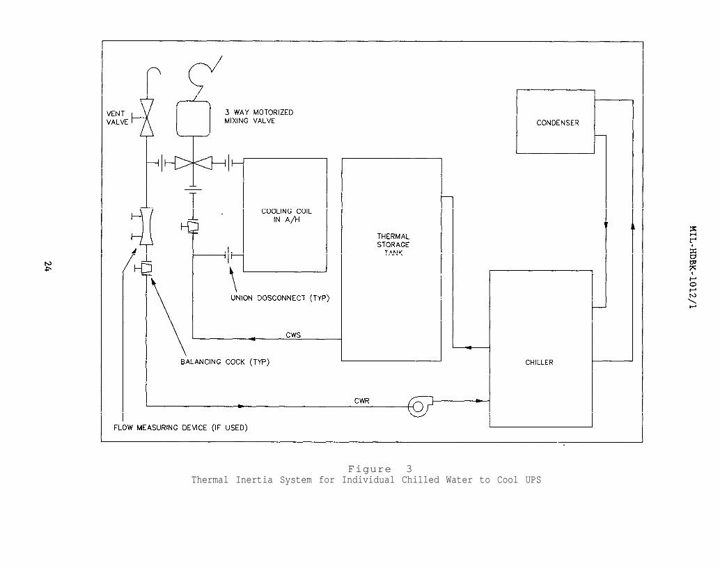
Figure 3Thermal Inertia System for Individual Chilled Water to Cool UPS

Figure 4Thermal Inertia System for Central Chilled Water to Cool UPS

MIL-HDBK-1012/1
4.2.4.3 UPS Battery Rooms. The most important environmental control systemrequirement of the battery room is to keep the battery electrolyte within anacceptable range of temperature. Normally, this can be done by heating andventilation only. Ventilation is also necessary to limit hydrogenaccumulation within the room. Batteries used with UPS equipment give offnegligible heat and low volumes of hydrogen gas when being charged. The highthermal inertia of the battery electrolyte causes its temperature to floatbetween the daily ambient temperature extremes; therefore, acceptableelectrolyte temperatures can be maintained by heating and ventilating, eventhough the ventilated room temperature may approximate the outside ambienttemperature.
a) Ventilation. The ventilation rate required is dependent uponthe hydrogen evolution rate which, in turn, depends on the type, size,temperature, charging rate, and number of cells in the battery bank. Hydrogengas evolution is highest during the last hours of an equalizing charge whenmost of the batteries will be fully charged and the charging energy is simplyhydrolizing the electrolyte. During this period and at 760 millimeters (mm)of mercury absolute atmospheric pressure, one cell will release hydrogen atthe rate of 0.016 cubic feet per hour (ft3/h) of hydrogen for each ampere ofcharging current flowing.
One fully charged lead calcium cell, with 1.215 specific gravityelectrolyte, at 77 degrees F (25 degrees C) temperature, will pass 0.24amperes of charging current for every 100 ampere-hour cell capacity (measuredat the eight-hour rate), when subject to an equalizing potential of 2.33volts. This current will double/halve for each 15 degrees F (8 degrees C)rise/fall in temperature.
The required capacity of a cell (ampere-hours at the eight-hourrate) and the number of cells for a given UPS application depends on the UPSsize, design and operating time. Where several UPS and battery brands areavailable, a variety of combinations are possible.
To calculate the required rate of ventilation for the battery bankof a 750KVA Emerson UPS (for example), consisting of 182 GNB Inc. cells, typePDQ-27, each having a nominal 1360 AH capacity at the eight-hour rate andbeing equalized at an electrolyte temperature of 92 degrees F (33 degrees C),proceed as follows:
26

MIL-HDBK-1012/1
EQUATION: Hydrogen Rate (HR) = 0.016 x 0.24 x 2 x 1360 x 182 = 0.317 CFM (1)60 100
Where:
0.016 = hydrogen emission rate per cell per ampere charge (ft3/h)60 = number of minutes per hour
0.24 = charging current per 100 AH cell capacity at 77 degreesF (ampere)
2 = doubling factor for 15 degrees F (8 degrees C) rise inelectrolyte temperature (above the normal 77 degrees F(25 degrees C))
1360 = capacity of one cell at the eight-hour rate (ampere-hour)100 = increment of cell capacity that will pass 0.24 ampere
current charge (ampere-hour)182 = number of cells
Concentrations of hydrogen below four percent are not flammable.To meet the Occupational Safety and Health Act (OSHA) requirements, limithydrogen concentration to one percent. The required ventilation rate is:
EQUATION: Ventilation Rate (VR) = 0.317 CFM = 31.7 CFM0.01
(2)
Notice that this is a small volume. Other factors, such as, lighting, otherequipment and solar-thermal gains, will require additional ventilation.Therefore, a ventilating rate of no less than 400 CFM should be considered.To provide redundancy, use two fans, each sized for half the flow. Fans maybe wall-mounted, roof-mounted, or ducted in-line. Makeup air shall befiltered as previously specified. A schematic of the heating and ventilatingscheme is shown in Figure 5. Fans shall be on the utility power circuit.
b) Heating. The preferred method of heating UPS battery rooms isa simple ducted arrangement using waste heat from the UPS equipment. Backupheat would then be required only when the UPS equipment is down formaintenance or repair. Electric resistance unit heaters are preferred,because of low first cost maintenance and utilization. The heater should beon the utility power circuit.
c) Controls. In the scheme depicted in Figure 5, the modulatingdamper should be controlled in winter by a wall-mounted thermostat, set at 65degrees F (18 degrees C). A switch should make it possible to bypass thethermostat in the summer to fully close the damper in the branch duct from theUPS equipment exhaust irrespective of temperature to take full advantage ofdaily range and to obtain a lower electrolyte temperature within the specifiedrange. Dampers should be of the low-leakage type. Fans should runcontinuously, except when de-energized by the firestat. Fan failure alarmsand hydrogen gas buildup alarms are not required. Fans should, however, be
27
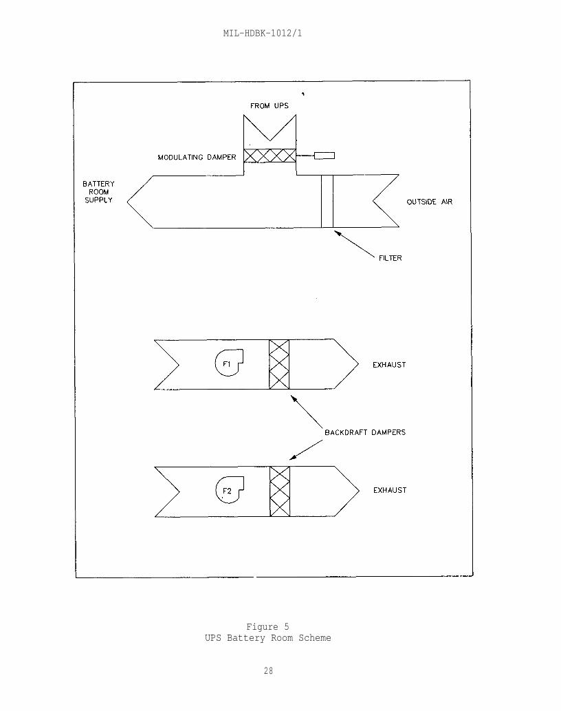
MIL-HDBK-1012/1
Figure 5UPS Battery Room Scheme
28
MIL-HDBK-1012/1
observed daily to insure they are both operating. If the fans are of amaking observation difficult, then a failure alarm should be considered
type
d) Safety features. Battery rooms shall comply with OSHAregulation 1926.403, Battery Rooms and Battery Charging.
4.2.4.4 Shielded Enclosures. HVAC systems for areas that requireelectrical and/or acoustical shielding should be one of two types:
a) Electrically shielded enclosures. For these areas, supply andreturn ducts penetrating the shield shall be provided with radio-frequency(RF) cutoff cores at the penetration points. Temperature and humidity controlsensors shall be located in the return air duct outside the enclosure ratherthan the space itself to avoid filters in the control wiring. Requirementsfor backup, inside design temperatures and similar factors shall be asindicated in the BESEP for the specific facility type.
b) Electrical/acoustical shielded enclosure. Air handlers withinthe room should be considered to avoid large supply and return ducting.Minimum sized fresh air supply/exhaust openings or ducts will still benecessary and must have RF cutoff cores and acoustic attenuators. Temperatureand humidity controls can then be within the room and control wires need notpenetrate the shield. This method requires only that power for the fan, plusa few watts for control, penetrate the shield, and therefore limits the powerthat must be filtered. The air handler in the room may use direct expansion,chilled water, steam or hot water coils supplied via piping from remoteheating and cooling units. The advantage is that main power for thesefunctions need not enter the room, eliminating the need to filter it. The
piping penetrating the shield must be metallic, must be bonded to the shield,and must be long enough to ensure RF cutoff.
4.3 Plumbing. Plumbing systems shall be in accordance with NAVFAC DM-3.01, Plumbing Systems. Special requirements not covered by DM-3.01 are asfollows:
4.3.1 Battery Rooms. UPS battery rooms and other spaces containingelectrolytic solution must be provided with emergency showers and eye washfacilities, as specified in OSHA 1926.403, Battery Rooms and Battery Charging.
4.3.2 Shielded Enclosures. Domestic water and other plumbing pipingpenetrating the shield must be bonded to it to ensure RF cutoff.
4.3.3 Transportables. Generally, the requirements of DM-3.01 do notapply to the tactical type of transportable.
4.4 Fire Protection. Design of fire protection and signaling systemsis covered by MIL-HDBK-1008 and MIL-HDBK-1190. Fire protection signalingsystems are briefly discussed in Section 5 of this handbook. The followingdiscussion is intended only to highlight data contained in the referencedocuments which should be consulted for more detailed guidance.
4.4.1 Areas Not Containing Electronic Equipment. Offices, classrooms andsimilar spaces are usually sprinklered, especially if the building is of
29

MIL-HDBK-1012/1
combustible construction, or if large amounts of combustible material arecontained in the space. Most of these areas will be classified as lighthazard but some, such as auditoriums and classrooms, may be classified asordinary hazard. Wet-pipe sprinkler systems are normally required.
4.4.2 Electronic Equipment Areas, The classification of the hazarddepends on the type of equipment in the space and its other contents. Thedegree of fire protection required depends on the value of the equipment andits importance to the mission of the facility. Incidental electronic gear ofcomparatively small value does not require special treatment. Essentialelectronic systems installed in special buildings, rooms, areas, orenvironments, and where the value is high, require special treatment asdescribed in MIL-HDBK-1008A and below:
4.4.2.1 Classification of Hazard. MIL-HDBK-1008A classifies alloccupancies in accordance with the amount of combustibles and flammableliquids contained in the space and cites specific examples for eachclassification.
4.4.2.2 Fire Protection Systems. Systems appropriate for electronicfacilities include wet-pipe sprinkler systems, dry-pipe pre-action sprinklersystems, carbon dioxide (CO,) systems, halon systems and portable dry chemicalextinguishers.
4.4.2.3 Fire Detection and Alarm Systems. See Section 5 for specificrequirements.
4.4.2.4 HVAC System Interlocks. Specific requirements are given in NFPA9OA. Both MIL-HDBK-1008A and NFPA 90A indicate that, unless a speciallydesigned smoke exhaust system is provided, HVAC equipment should be de-energized upon receipt of a fire or smoke alarm.
30
MIL-HDBK-1012/1
Section 5: ELECTRICAL ENGINEERING
5.1 General. All electronic facilities operated by the Navy, howevervaried in function, have similar requirements for electrical energy,grounding, bonding, and shielding, which are set forth below. In addition,all standard electrical criteria for naval shore facilities are applicable.Specific guidance for particular facilities will be contained in the BESEP.The designer must be concerned with the general requirements as well as thespecifics in order to achieve an integrated and compatible electronic facilitydesign.
5.2 Electrical Power Requirements. The ability of an electronicfacility to perform its mission depends directly on the adequacy andreliability of the systems that supply and distribute its electrical power.An acceptable degree of power system reliability can be obtained only from theproper combination of primary, emergency, standby, uninterruptible, andconditioned power sources. Refer to MIL-HDBK-1004/1, Electrical Engineering -Preliminary Design Considerations, and MIL-HDBK-411, Power and EnvironmentalControl for Physical Plant OF DOD LONG HAUL COMMUNICATIONS, Volume I and II.
5.2.1 Power Sources. The primary electrical power source should besupplied by a commercial power company. Two independent sources with twoseparate feeders are required where they are available and economicallyfeasible (mission reliability/operational requirements versus cost). Ifcommercial power sources are unavailable or inadequate, an on-station primarypower plant is required. (Refer to MIL-HDBK-1004/1 for primary and alternatesource selections and load estimation.) Technical equipment powerrequirements will be furnished by the project's electronic engineers (SPAWAR).Design electrical capacity shall be for 100 percent of station demand load.Spare capacity for a minimum of 25 percent of the total facility load shall beprovided for future growth.
5.2.2 Load Categories. Electronic facility power loads are divided intocategories (see Figure 6) according to function and allowable downtime.
5.2.2.1 Station Load. The station load is the total power requirement ofthe electronic facility.
5.2.2.2 Nonoperational Load. The nonoperational load refers toadministrative, support, and miscellaneous power requirements not essential tofacility operation and does not normally require emergency power.
5.2.2.3 Onerational Load. The operational load is that portion of the loadrequired to keep the facility in continuous operation. (The sum of thetechnical and nontechnical loads.)
5.2.2.4 Nontechnical Load. The nontechnical load is that part of the totaloperation load used for general lighting, convenience outlets, airconditioning, ventilating equipment, and other functions for normal operationand does not normally require emergency power.
31
MIL-HDBK-1012/1
5.2.2.5 Technical Load. The technical load is that portion of theoperational load required for electronic equipment and ancillary equipment,including the lighting, air conditioning, and ventilation required for fullcontinuity of facility function. The operation of the technical load isessential to the mission of the facility and normally requires emergencypower.
5.2.2.6 Noncritical Technical Load. The noncritical load is that portionof the technical load not required for synchronous operation. This includesnonsynchronous electronic equipment, test equipment, emergency lighting,ventilation, and air conditioning for electronic equipment. The outage timetolerance for specific facilities will vary. Refer to BESEP for specificdata.
5.2.2.7 Critical Technical Load. The critical technical load is that partof the total technical load required for continuous synchronous operation ofelectronic equipment. This includes any equipment that will malfunctionduring a momentary power dropout and cause additional outage after power isrestored, as a result of the need to re-synchronize; loss of real time countby master time sources; or loss of data in ADP systems.
Government-furnished UPS equipment shall serve all criticaltechnical loads. The BESEP will specify the loads to be served by the UFS aswell as the size of the system.
5.2.3 Electrical Power Characteristics. Unless otherwise stated in theBESEP, the power characteristics normally will be as follows:
5.2.3.1 Voltage. Steady-state voltage variations shall not exceed plus orminus ten percent of the nominal voltage level.
a) For sites with separate power plants, the preferred voltage is480Y/277.
b) For other power sources, the preferred voltage is 208Y/120 forloads less than or equal to 300 KVA and 480Y/277 for loads greater than 300KVA.
5.2.3.2 Frequency. Steady-state frequency variations shall not exceed plusor minus five percent of the nominal frequency. The preferred frequency is 60hertz (Hz). If 60 hz is not available overseas, 50 hz is normally supplied.
5.2.3.3 Reliability. For technical load bus, reliability shall be 99.99percent, exclusive of scheduled outages, which must not exceed a total of 53minutes during any 1 year.
5.2.3.4 Dynamic or Transient Variation. Limitations at the operational busare:
a) Voltage; Minus 15 percent, plus 10 percent.
b) Frequency: Plus or minus 5 percent.
32

Figure 6Power Load Categories
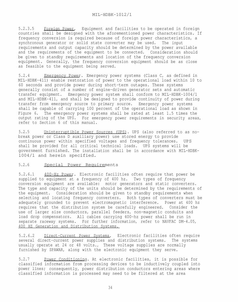
MIL-HDBK-1012/1
5.2.3.5 Foreign Power. Equipment and facilities to be operated in foreigncountries shall be designed with the aforementioned power characteristics. Iffrequency conversion is required because of foreign power characteristics, asynchronous generator or solid state converter may be used. The inputrequirements and output capacity should be determined by the power availableand the requirements of the equipment to be connected. Consideration shouldbe given to standby requirements and location of the frequency conversionequipment. Generally, the frequency conversion equipment should be as closeas feasible to the equipment being served.
5.2.4 Emergency Power. Emergency power systems (Class C, as defined inMIL-HDBK-411) enable restoration of power to the operational load within 10 to60 seconds and provide power during short-term outages. These systemsgenerally consist of a number of engine-driven generator sets and automatictransfer equipment. Emergency power system shall conform to MIL-HDBK-1004/1and MIL-HDBK-411, and shall be designed to provide continuity of power duringtransfer from emergency source to primary source. Emergency power systemsshall be capable of carrying 100 percent of the operational load as shown inFigure 6. The emergency power systems shall be rated at least 1.5 times theoutput rating of the UPS. For emergency power requirements in security areas,refer to Section 6 of this manual.
5.2.5 Uninterruptible Power Sources (UPS). UPS (also referred to as no-break power or Class D auxiliary power) use stored energy to providecontinuous power within specified voltages and frequency tolerances. UPSshall be provided for all critical technical loads. UPS systems will begovernment furnished. The installation shall be in accordance with MIL-HDBK-1004/1 and herein specified.
5.2.6 Special Power Requirements
5.2.6.1 400-Hz Power. Electronic facilities often require that power besupplied to equipment at a frequency of 400 hz. Two types of frequencyconversion equipment are available: motor generators and static converters.The type and capacity of the units should be determined by the requirements ofthe equipment. Consideration should be given to standby requirements whenselecting and locating frequency converters. Both types of converters must beadequately grounded to prevent electromagnetic interference. Power at 400 hzrequires that the distribution system be carefully engineered. Consider theuse of larger size conductors, parallel feeders, non-magnetic conduits andload drop compensators. All cables carrying 400-hz power shall be run inseparate raceway systems. For further information, refer to NAVFAC DM-4.05,400 HZ Generation and Distribution Systems.
5.2.6.2 Direct-Current Power Systems. Electronic facilities often requireseveral direct-current power supplies and distribution systems. The systemsusually operate at 24 or 48 volts., These voltage supplies are normallyfurnished by SPAWAR, along with the electronic equipment they serve.
5.2.7 Power Conditioning. At electronic facilities, it is possible forclassified information from processing devices to be inductively coupled intopower lines; consequently, power distribution conductors entering areas whereclassified information is processed may need to be filtered at the area
34

MIL-HDBK-1012/1
boundary. Specific guidance concerning the treatment of such power and signalcabling will be contained in the BESEP.
In general, primary power distribution and protection should beoutside classified areas to facilitate access for maintenance. Normal powerdistribution design for electronic equipment areas requires consideration ofthe peculiarities of communication and electronic equipment. For example,low-level signals in the microvolt range and a large frequency spectralenvironment would suggest that power lines be routed as far away as possiblefrom the nearest antenna. Radio-frequency noise sources such as generators,air conditioning compressors, and switchgear should be located to minimizephysical and electrical interference with electronic equipment.
Voltage transient protection should be installed on both transientsources and power distribution points for electronic equipment. Commercialpower conditioning equipment, containing instrumentation and alarmcapabilities as well as active and passive protection devices, may benecessary to provide the quality of power appropriate to the equipment beingsupported.
5.2.8 Electrical Distribution Systems. The electrical distributionsystem shall be designed in accordance with NFPA 70 National Electrical Code.Consideration should be given to providing a flexible system that will meetthe facility's future requirements. Electronic equipment is constantly beingupgraded, modified, and replaced. Bus duct systems and cable trays may proveto be the most flexible system in areas where new equipment is expected orwhere frequent modification may occur. The BESEP will provide equipment listswith power requirements for each piece of electronic equipment, includingmaximum load, voltage characteristics, and special requirements. All maintransformers serving electronic facilities shall have lightning protectors onboth the primary and the secondary side of the transformer.
5.2.8.1 Load Category. Each load category shall be fed as shown inFigure 7.
5.2.8.2 Circuit Breakers. Separate circuit breakers shall be provided atpower panels for each equipment rack, cabinet, or piece of electronicequipment. Individual pieces of equipment shall be connected to thepanelboards by wiring run in cable racks or conduits or a combination of both.Bolt-on circuit breakers should be used in electronic facilities.
5.2.8.3 Cable Vaults. Most buildings require underground radio-frequencycable, communication cable (telephone type), control cable, and power cable.These cables shall enter the building through two cable vaults, one for signalcables and one for power cables, These vaults shall also house the protectivedevices used to prevent surges from entering the building. The vaults shallbe designed in accordance with the latest safety standards.
5.2.8.4 Wiring. Wiring to each piece of equipment shall be sized to carryfull load current. Maximum voltage drop shall be in accordance with NFPA 70.
35

MIL-HDBK-1012/1
5.2.8.5 Receptacles.convenience outlets shallfrequency.
All receptacles other than 120-volt, general-purpose be marked with voltage, amperage, phase, and
5.2.8.6 Neutral Conductors. Full-size neutral conductors shall be usedthroughout the distribution system. Requirements for oversized neutralconductors shall be provided in the BESEP.
5.2.8.7 Grounding Conductors. Greenwire equipment grounding conductorsshall be sized in accordance with NFPA 70. Requirements for oversizedgrounding conductors shall be provided in the BESEP.
5.2.8.8 Cableways. Cable shall be routed through trays or ducts suspendedoverhead. When raised flooring is used, cable shall be run in conduit withinthe space under the floor in accordance with the requirements of NFPA 70.
5.2.8.9 Bus Ducts. Bus ducts may be used as required.
5.2.8.10 Power Line Transient Protection. Transient overvoltagedisturbances varying in severity and rate of occurrence are found in all powerdistribution systems. Sensitive electronic equipment exposed to thesetransients may be disrupted or, in some cases, damaged. Therefore, surgeprotection using Metal Oxide Varistors (MOV's), or similar devices, shall beinstalled at the load side of the main distribution switchgear. Select an MOVwith a rating of less than 125 percent of the root-mean-square (rms) line-to-ground voltage. It is recommended that the largest joule rating and thelowest clamping level for the specific rms voltage rating be selected.
5.3 Lighting Systems. Interior lighting, roadway lighting, protectivelighting, and area lighting systems shall be designed in accordance with MIL-HDBK-1004/1. Lighting levels shall be in accordance with the latest revisionof the Illuminating Engineers Society (IES) Lighting Handbook, and MIL-HDBK-1190. In case of conflict, MIL-HDBK-1190 takes precedence over IES criteria.
5.3.1 Emergency Lighting. Battery-powered emergency lighting units shallbe provided in all operational spaces, including the emergency generator roomsand UPS rooms. All battery-powered emergency lighting units shall conform tothe requirements of Federal Specification W-L-305, Light Set, GeneralIllumination (Emergency or Auxiliary). Special requirements shall be providedin the BESEP.
5.3.2 Fluorescent Fixtures. Unless otherwise specified in the BESEP,fluorescent fixtures may be used. Power line filters shall be installed asset forth in the BESEP.
5.3.3 Consoles. Consideration should be given to the use of indirectand/or dimmable lighting in equipment console operating spaces to reduce glareon equipment display panels.
5.3.4 Antenna Areas. Electric vapor lamps shall not be used within 1/2mile (805 m) of receiving antennas.
36

MIL-HDBK-1012/1
Figure 7Typical Bus Configuration for New Facilities
37
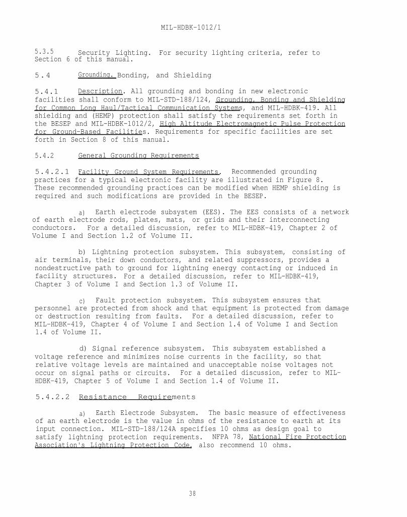
MIL-HDBK-1012/1
5.3.5 Security Lighting. For security lighting criteria, refer toSection 6 of this manual.
5.4 Grounding. Bonding, and Shielding
5.4.1 Description. All grounding and bonding in new electronicfacilities shall conform to MIL-STD-188/124, Grounding, Bonding and Shieldingfor Common Long Haul/Tactical Communication Systems, and MIL-HDBK-419. Allshielding and (HEMP) protection shall satisfy the requirements set forth inthe BESEP and MIL-HDBK-1012/2, High Altitude Electromagnetic Pulse Protectionfor Ground-Based Facilities. Requirements for specific facilities are setforth in Section 8 of this manual.
5.4.2 General Grounding Requirements
5.4.2.1 Facility Ground System Requirements. Recommended groundingpractices for a typical electronic facility are illustrated in Figure 8.These recommended grounding practices can be modified when HEMP shielding isrequired and such modifications are provided in the BESEP.
a) Earth electrode subsystem (EES). The EES consists of a networkof earth electrode rods, plates, mats, or grids and their interconnectingconductors. For a detailed discussion, refer to MIL-HDBK-419, Chapter 2 ofVolume I and Section 1.2 of Volume II.
b) Lightning protection subsystem. This subsystem, consisting ofair terminals, their down conductors, and related suppressors, provides anondestructive path to ground for lightning energy contacting or induced infacility structures. For a detailed discussion, refer to MIL-HDBK-419,Chapter 3 of Volume I and Section 1.3 of Volume II.
c) Fault protection subsystem. This subsystem ensures thatpersonnel are protected from shock and that equipment is protected from damageor destruction resulting from faults. For a detailed discussion, refer toMIL-HDBK-419, Chapter 4 of Volume I and Section 1.4 of Volume I and Section1.4 of Volume II.
d) Signal reference subsystem. This subsystem established avoltage reference and minimizes noise currents in the facility, so thatrelative voltage levels are maintained and unacceptable noise voltages notoccur on signal paths or circuits. For a detailed discussion, refer to MIL-HDBK-419, Chapter 5 of Volume I and Section 1.4 of Volume II.
5.4.2.2 Resistance Requirements
a) Earth Electrode Subsystem. The basic measure of effectivenessof an earth electrode is the value in ohms of the resistance to earth at itsinput connection. MIL-STD-188/124A specifies 10 ohms as design goal tosatisfy lightning protection requirements. NFPA 78, National Fire ProtectionAssociation's Lightning Protection Code, also recommend 10 ohms.
38
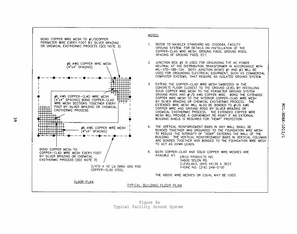
Figure 8aTypical Facility Ground System
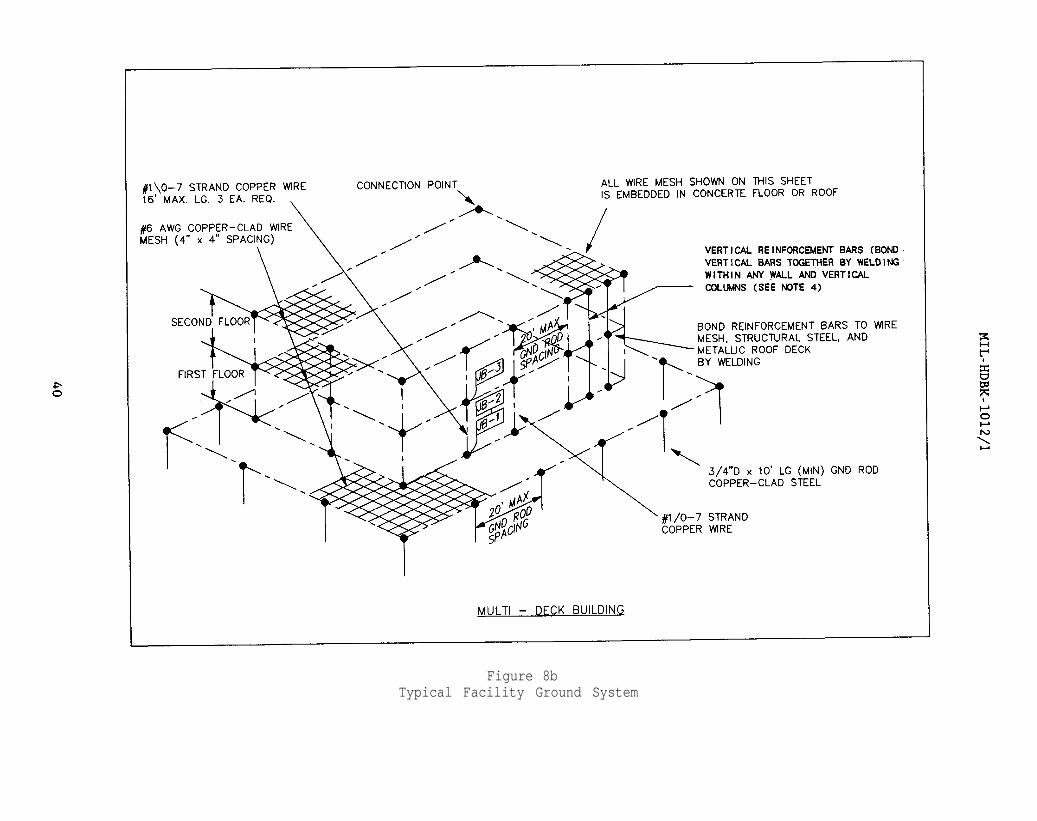
Figure 8bTypical Facility Ground System
MIL-HDBK-1012/1
b) Fault protection subsystem. NFPA 70, in Article 250, requiresthat a single electrode consisting of a rod, pipe, or plate, and not having aresistance to ground of 25 ohms or less, be augmented by additional madeelectrodes.
c) Qualification of NFPA 70 resistance requirements. MIL-STD-188/124A establishes a design goal, of 10 ohms for facility ground systems.Where this is not possible, alternative methods should be considered forreducing resistance to the lowest feasible resistance-to-ground value. Fordetailed discussions and applications, refer to MIL-HDBK-419, Sections 2.6 and2.9 of Volume I and Section 1.2 of Volume II.
d) Lightning protection subsystem. For lightning protection, agrounding resistance of 10 ohms or less is recommended. For a detaileddiscussion, refer to MIL-HDBK-419, Sections 2.6, 2.9, 3.7, and 3.8 of Volume Iand Section 1.3 of Volume II.
5.4.3 Specific Grounding Requirements
5.4.3.1 Electronic Equipment. Each piece of electronic equipment shall beserved by a green ground wire carried in the same cable or conduit as thepower service to the equipment.
5.4.3.2 Distribution Service: The neutral of the distribution service.shall be grounded only at the main service entrance, at which point it shallbe grounded to the EES.
5.4.3.3 Security Fence. Permanent security fencing normally requires agrounding system to ensure personnel safety and, in some instances, to preventre-radiation of signals. Grounded security fence shall be constructed ofgalvanized chain-link fencing with bonded connections at all intersections, orwith a No. 8 American Wire Gage (AWG) (minimum) copper conductor woven throughthe fabric of the entire length of the fence. The wire addition shall not besubstituted for the top rail of the fence. The supporting posts and top railsshall be made of electrically conductive material. Both the fence posts andthe fence fabric or conductor wire shall be grounded by an 8-foot ground rodat alternate fence posts. When a gate is incorporated, its hinges shall bebonded with flexible No. 8 AWG copper wire. These wires shall be connected tothe gate post and the frame of the gate using exothermic welding or approvedpressure connectors. No fencing material shall be installed which has beencovered with non-conductive material.
5.4.4 General Bonding Requirements. Steel framing shall be bonded to thefacility's ground system. Vertical columns shall be bonded at the top andbottom. Reinforcing steel shall be bonded 10 feet (3.05 m) on center eachway, unless otherwise specified. Helix houses and most LF facilities havemore stringent bonding requirements and shall be bonded according to thecriteria set forth in this manual and the project BESEP.
5.4.5 Specific Bonding Requirements
5.4.5.1 Cable Trays. Cable trays shall be used as part of the overallsystem bonding scheme. Tray sections shall be bonded together to provide a
41
MIL-HDBK-1012/1
continuous electrical path. Trays shall be bonded to equipment housings bywide, flexible, solid bond straps. For a detailed discussion, refer to MIL-HDBK-419, Section 1.7.4.1 of Volume II.
5.4.5.2 Tubing and Conduit Long spans of conduit shall be bonded to thestructure at both ends and at several intermediate points.
a) Flexible conduit. A flared, split-sleeve clamp shall be usedto prevent deformation of flexible conduit.
b) Rigid conduit. Ordinary clamps may be used on rigid conduit.
c) For a detailed discussion, refer to MIL-HDBK-419, Section1.5.4.2 of Volume II.
5.4.6 General Shielding Requirements. Shielding requirements shall be asset forth in the BESEP. For a detailed discussion, refer to MIL-HDBK-419,Chapter 8 of Volume I, Section 1.6 of Volume II and MIL-HDBK-1012/2.
5.4.7 Specific Shielding Requirements
5.4.7.1 Shielded Enclosures/Screen Rooms. General requirements forattenuation are normally 60 dB for existing facilities and 100 dB for newfacilities. Specific requirements shall be as set forth in the BESEP.Penetration holes and discontinuities are discussed in MIL-HDBK-419, Chapter 8of Volume I and MIL-HDBK-1012/2.
5.4.7.2 Tempest. In general, shielding to provide security will requireTEMPEST shielded enclosures. The normal attenuation is 100 dB. Specificrequirements shall be as set forth in the BESEP.
5.4.7.3 HEMP HEMP protection shall be provided as indicated in MIL-HDBK-1012/2 and the BESEP.
5.5 HEMP Protection. The detonation of a nuclear device at highaltitudes produces extremely high electromagnetic transients over a largegeographical area. This phenomenon is referred to as HEMP. The primaryeffect of HEMP is the production of large voltages and currents in conductorssuch as power lines, telephone lines, metallic fences, buried cables, andantennas. These induced voltages and current may cause secondary effects,such as insulation flashover and equipment malfunction and/or damage. Solid-state electronic devices are especially susceptible to transients such asthose produced by HEMP.
Consideration should be given to providing HEMP protection for allcritical electronic facilities through the use of voltage-limiting surgearresters, low-pass filters, shielding, and other devices such as varistorsand carbon blocks. Bonding and grounding requirements for HEMP protection areset forth in MIL-HDBK-1012/2. Shielding requirements for HEMP protection willbe specified in MIL-HDBK-1012/2 and the BESEP.
5.6 Energy Conservation. Every effort should be made during design tominimize the use of energy over the life of a facility, insofar as the
42

MIL-HDBK-1012/1
facility's mission and system reliability will allow. Where energy monitoringand control systems (EMCS) are already installed on the base, consider addingthe new facility to the system. Refer to NAVFAC DM-4.09, Energy Monitoring and Control Systems, for design methods in accordance with NFGS 13947, EMCS,Large System Configuration, through 13950, EMCS, Micro System Configuration.In addition, the following items should be considered:
5.6.1 Metering. Provide metering to measure energy consumption.Consider kilowatt-hour and demand meters for the total facility, operationalload bus, and technical load bus.
5.6.2 Power Factor. Maintain a high power factor; provide power factorcorrection, when required, to maintain a minimum power factor of 85 percent atpeak load.
5.6.3 Motors. All motors 1 horsepower and above shall be three-phasemotors. Consider high-efficiency motors for all HVAC and auxiliary equipment.
5.6.4 Lighting. General illumination levels should not exceed specifiedlevels. Provide task lighting to supplement general lighting, as required.
5.6.5 Lighting Control. Provide additional switching to reduce energyused for lighting unoccupied areas.
5.7 Fire Alarm and Detection Systems. Fire alarm and detection systemsshall provide maximum fire protection for personnel and equipment consistentwith the function of the facility. Fire alarm and detection systems shallconform to the requirements of MIL-HDBK-1008, NFPA 72A, Standard for theInstallation. Maintenance. and Use of Local Protective Signaling Systems forGuard's Tour, Fire Alarm. and Supervisory Service, and NFPA 72E, AutomaticFire Detectors. Electronic facilities shall be provided with manual andautomatic fire reporting systems to transmit the following signals:
5.7.1 Onsite Signal. To building occupants, to permit prompt correctiveaction and/or evacuation.
5.7.2 Offsite Signal. To fire department headquarters or another centraloffice that will implement emergency action.
5.7.3 System Signal. To actuate automatic fire extinguishing equipment.
Because overheating or malfunctioning electronic equipment must bedetected as early as possible, automatic supervision of all alarm circuitsshall be provided. Automatic fire detection shall be provided in electronicequipment areas, in record storage rooms, and under raised floors.
5.8 Signal Systems. Design of signal systems shall be as specified inNAVFAC DM-4.07, Wire Communication and Signal Systems.
43

MIL-HDBK-1012/1
THIS PAGE INTENTIONALLY LEFT BLANK
44
MIL-HDBK-1012/1
Section 6: PHYSICAL SECURITY
6.1 General. Physical security is concerned with limiting,controlling, or preventing personnel access to specific areas. A soundphysical security program is the result of good planning. The best and mosteconomical programs are those incorporated in the facility's design andconstruction. The facility's configuration and location; the use of barriers,protective lighting, particular kinds of construction, intrusion detectionalarms, closed circuit television (CCTV), and security fencing; and the guardcommunication network must be coordinated with the using agency to ensureconformance with the installation's security plan. The mode of operation,level of security, and designer's responsibility for particular securityelements will be designated in the BESEP.
6.2 Exterior Physical Security. External security requirements in mostcases depend on the internal security measures provided in the facility designand on the type of protection required. Normally, external considerations,including building location and orientation and the use of protective barriersand lighting, are developed as part of the facility's security plan andspecified in the BESEP. DIAM 50-3, Physical Security Standards for SensitiveCompartmented Information Facilities, and MIL-HDBK-1013/1 should be theprimary criteria sources for design of the required facilities.
6.2.1 Perimeter Fencing. Generally, chain-link fencing is used forpermanent areas. General-purpose barbed tape obstacle and concertina wire areused for temporary installations or where the terrain does not allowconstruction of chain-link fencing. Dual perimeter barriers are described inDIAM 50-3. Alternative fence configurations are discussed in MIL-HDBK-1013/1.The following requirements are the minimum for normal protection:
a) Unless otherwise specified, the perimeter security fence shallbe at least 50 feet (15.24 m) from enclosed structures (except guardshelters). A clear zone not less than 20 feet (6.1 m) wide shall be providedimmediately outside the fence. This area shall be devoid of buildings,parking areas, poles, guy line anchors, shrubs, trees, sign boards, and anyother object that could conceal personnel. Grass is permissible, provided itis kept mowed. A similar clear zone at least 50 feet (15.24 m) wide shall beprovided immediately inside the fence. This area shall meet the requirementsof the exterior clear zone, except that approved guard shelters and protectivelighting poles may be installed.
b) Chain-link fencing shall conform to the latest issue of FederalSpecification RR-F-191, Fencing, Wire (Chain-Link Fabric). The fence fabricshall be 6 feet (1.83 m) high, unless other requirements are provided by thesponsor. The fence shall be topped by a 45-degree outrigger that is 15 to 18inches (381 to 457.2 mm) long. Three evenly spaced strands of barbed wireshall be attached to the outriggers. All fence fabric and barbed wire strandsshall be grounded.
c) Utility openings, covers, sewers, culverts, tunnels, and othersubsurface routes which penetrate the fence line shall be protected inaccordance with DIAM 50-3.
45

MIL-HDBK-1012/1
d) The number of gates and perimeter entrances shall be reduced tothe minimum required for safe and efficient operation.
e) Guard shelters shall be provided when required by the BESEP.
6.2.2 Security Lighting. Lighting shall be installed inside theperimeter security fence in a manner to illuminate the fence completely and toprevent an intruder from using the light poles and guy wires to gain access tothe area. Illumination shall be in accordance with the lightingspecifications in Tables 20 and 21 of MIL-HDBK-1013/1.
a) Illuminate areas shadowed by structures.
b) Ensure that failure of one lamp in a circuit will not affectother lamps in the same circuit.
c) Provide overlapping light distribution to minimize reductionsin illumination levels upon lamp failure.
d) Protect all components of the system from vandalism.
e) Provide lights on buildings.
f) Provide an emergency power generator within the security area.
The emergency power source shall be adequate to sustain protective lighting ofall critical areas and structures for 8 hours and shall go into operationautomatically when the primary power fails. The facility shall havegenerator- or battery-powered lights at key control points in case a failuredisables the secondary power supply.
g) Install special-purpose lighting (such as for fog penetration)when climatic or other local factors dictate.
h) Provide additional lighting for (CCTV) security surveillance,as necessary.
6.2.3 Protective Alarm Systems. Operational sites constructed inaccordance with physical security criteria set forth in this manual normallywill not require extensive protective alarm systems. The EquipmentApplication Guide for Joint-Service Interior Intrusion Detection System (J-SIIDS) Equipment provides information on intrusion detection alarm devicesthat meet most Navy requirements. The BESEP or the user command will providespecific intrusion detection system requirements.
6.2.4 CCTV. Because of reduced personnel levels, CCTV may be required tosupplement the guard force. The BESEP or the user command will specify theserequirements, if applicable.
6.3 Interior Physical Security
6.3.1 Delay Times. Guidelines for selecting and designing facilitycomponents to meet specified delay times are provided in MIL-HDBK-1013/1
46

MIL-HDBK-1012/1
Procedures for determining delay times, if not specified by the BESEP or theuser command, are given in MIL-HDBK-1013/1.
6.3.2 Building Layout. Portions of the building requiring specialsecurity consideration will be identified by the BESEP or by the user command.
6.3.3 Wall Construction. Secure area wall construction shall be 4 inches(100 mm) of reinforced concrete or 8 inches (200 mm) of solid masonry,normally without windows and with controlled access. For detailedrequirements, refer to DIAM 50-3.
6.3.4 Roof and Floor Construction. At least 4 inches (100 mm) ofreinforced concrete will normally be used for roof and floor construction.Hardening methods for other types of construction are provided in MIL-HDBK-1013/1. False ceilings or raised floors may provide a means of concealment.These ceilings or floors are considered part of the protected area to whichthey are attached, and the true walls, floor, and ceiling must meet theapplicable requirements. Suspended false ceilings shall have at least one"quick-remove" access panel 18 by 18 inches (460 by 460 mm) for each 400square feet (37.2 square meters of ceiling area. Raised floorsmust be similarly equipped.
6.3.5 Perimeter Doors. Entry and exit doors of secure areas shall be asspecified in the BESEP or DIAM 50-3. Normally, a 1-3/4-inch (44.5 mm) solidwood door will suffice for a continuously operating facility.
6.3.6 Windows. Windows are not authorized in secure areas.
6.3.7 Air Vents and Ducts Vents, ducts and other openings that breachthe facility perimeter require protection as specified in DIAM 50-3.Normally, any opening which exceeds 6 inches (152.4 mm) requires protection.
6.3.8 Miscellaneous Hardware
6.3.8.1 Roof Doors and Hatches. Roof doors and hatches shall be internallysecured with padlocks and hasps in conformance with the provisions of MilitarySpecification (Mil Spec.) MIL-P-43607, Padlock, Key Operated, High Security,Shrouded Shackle. Roof doors may also be equipped with a cylindrical case orbored lockset. Such locksets, when installed, shall be mounted with the lockcylinder to the exterior.
6.3.8.2 Coded Locks. If required for control of routine access, anelectrically controlled and operated latch mechanism for interior doors shallbe installed. RF emissions shall meet the requirements of MIL-STD-461,Electromagnetic Emission and Susceptibility Requirements for the Control ofElectromagnetic Interference, for class II-A equipment. Such mechanisms shallnot mate or interface with other required locksets. Separate surface-mountednight latches or specialty hardware shall be added to the door to accommodatethe electrically operated mechanism. Key-operated bypass cylinders are notauthorized.
47

MIL-HDBK-1012/1
6.3.9 Vaults. Vaults or vault construction will be specified by theBESEP or the user command. Specific criteria for construction andinstallation are given in DIAM 50-3.
6.3.9.1 Safety and Emergency Devices. Vault doors shall be equipped withan emergency escape device and with the following:
a) A luminous light switch.
b) An emergency light (if the vault is otherwise unlighted).
c) An interior alarm switch or other device (such as a telephone)to permit a person in the vault to communicate with a vault custodian, guard,or guard post.
d) Instructions on obtaining release shall be permanent affixed tothe inside of the door or prominently displayed elsewhere inside the vault.
e) A bank vault ventilator approved by Underwriters Laboratories,Inc., if the vault is not otherwise served by forced air ventilation.
6.3.9.2 Fire Protection. The vault shall be equipped with at least one fire extinguisher approved by Underwriters Laboratories (UL), Inc.
48

MIL-HDBK-1012/1
Section 7: SAFETY
7.1 General. The presence of Electromagnetic Radiation (EMR) attransmitter sites poses potential hazards to personnel, including directexposure to EMR, shock and burns, and detonation of fuel and ordnance. Thepresence of transmitting and receiving structures at communication sites posespotential hazards to aircraft. SPAWAR normally will identify and analyzethese hazards during site selection, and will be responsible for planning sitelayout to eliminate or avoid them. The project BESEP will identify anyprotective measures required. The designer must be aware of the hazardsassociated with these facilities, and, during the normal phases of design,shall bring them to the attention of the agency responsible for the design.Other hazards associated with electronic facilities include electrical shock,electrical fire, toxic and explosive gases from batteries, ozone from coronadischarge and noise from teletypes and cooling fans. Facilities must includeadequate electrical isolation, insulation, fire protection, ventilation, andacoustical absorption to provide a safe and healthful environment.
7.2 Human Engineering. The designer must consider safety not only inrelation to operator functions and accessibility for maintenance and repair,but also in relation to physical layout for traffic, interface with otherequipment, and environmental factors, such as lighting, temperature, andhumidity. The basic references are MIL-STD-882, System Safety ProgramRequirements, and MIL-STD-1472, Human Engineering Design Criteria for MilitarySystems. Equipment and Facilities.
7.3 Radiation Hazards
7.3.1 Hazards to Personnel. RF radiation can be harmful if the bodyabsorbs radiated energy and physical contact with induced voltages can resultin shock or RF burns.
7.3.1.1 Absorbed Radiation
a) Personnel exposure limits to RF radiation are defined inOPNAVNOTE 5100, Ser 45/5U394867 of 30 July 1985, Personnel Protection Policyfor Exposure to Radio-Frequency Radiation (RFR). Personnel shall not beexposed to a power density which, when averaged over any O.1-hour period,exceeds those values listed in Table 3 in the frequency domain of 10 kHz - 300GHz. Neither the root mean squared electric field strength (E) nor the rootmean squared magnetic field strength (H) may exceed those values when averagedover any O.1-hour period (refer to Table 3).
49

MIL-HDBK-1012/1
7.3.2.1 Hero Unsafe. HERO UNSAFE ordnance materials are the mostsusceptible to RF radiation and constitute the "worst-case" situation forshore communication transmitters. An ordnance item is defined as HERO UNSAFEwhen any of the following conditions exist:
(a) When its internal wiring is physically exposed.
(b) When additional electrical connections are required for theitem being tested.
(c) When EED's with exposed wire leads are handled or loaded.
(d) When the item is being assembled or disassembled.
(e) When the item remains disassembled.
7.3.2.2 Exemption. Ordinance items may be exempted from the HERO UNSAFEclassification as the result of previous HERO tests or analyses which arerecorded for specific equipment in the NAVSEA/NAVAIR directive.
7.3.2.3 Field Intensity Measurements. Measurements of field intensity willascertain the magnitude of an electromagnetic field. The field intensity ofelectromagnetic fields at communication frequencies (100 kHz to 1000 MHz) isreferred to in terms of vertical electric field strength in units of volts permeter. A chart in NAVSEA OP3565/NAVAIR 16-1-529/NAVELEX 0967-LP-624-6010indicates that, for HERO UNSAFE ordnance, the maximum safe field intensity is0.2 V/m throughout the 2 to 32 MHz frequency range. This criterion couldbecome a stringent restriction for radiation from communication transmittersof reasonably high power.
7.3.2.4 Hero Safe. HERO SAFE ordnance systems are not susceptible toradiation under any condition.
7.3.2.5 Hero Susceptible. Many ordnance systems are classified as HEROSUSCEPTIBLE under most conditions. The maximum safe field intensityprescribed for HERO SUSCEPTIBLE ordnance is 2.0 V/m from approximately 3.7 to10.1 MHz frequency range.
7.3.2.6 Safe Distances. Since the maximum safe field intensity varieswidely for the three classifications of ordnance, it is important to ascertainwhether ordnance systems will be handled or stored in the vicinity of atransmitter site. Refer to NAVSEA OP3565/NAVAIR-16-1-529/ NAVELEX 0967-LP-624-6010 for safe distances from specific antennas.
If so, the classification of the ordnance most sensitive to RF radiation willdetermine the maximum field strength that can be tolerated.
7.3.3 Fuel Hazards. General guidance to prevent hazards to fueling in anRF environment are provided in NAVSEA OP3565/NAVAIR 16-1-529/NAVELEX 0967-LP-624-6010 Volume 1 and is as follows: Transmitters with 250 watts radiatedoutput or less should not be installed within 50 feet (15 m) of fuel-handlingor fueling areas. Transmitters with over 250 watts radiated output should notbe installed within 200 feet (61 m) of fuel-handling or fueling areas. In no
51

MIL-HDBK-1012/1
case should power density in the fueling area be greater than would exist at adistance of 50 feet (15 m) from radiated output of 250 watts. See Figure 9.
7.3.3.1 Bonding and Grounding. Where space limitations require thelocation of fueling stations, parking ramps, or other structures near anantenna site, all metal used in wooden structures within 200 feet (61 m) offixed antennas radiating 250 watts or more shall be bonded together andgrounded to reduce interference and fire hazards.
7.3.3.2 Antenna Position. If possible, antennas shall be positioned toprevent radiation of fueling areas while in operation. Otherwise, minimumdistances given above shall be employed.
7.4 Isolation and Warning Devices
7.4.1 Fence. Only nonconducting materials are suitable for protectivefences for antennas. Usually, a wood fence from 4 to 6 feet high (1.2 to1.8 m) will provide adequate protection. Gates shall be designed andinstalled so that accidental entry into the hazardous area is not possible.
7.4.2 Warning Signs. Carefully worded and illustrated signs shall beposted conspicuously to prevent personnel from contacting high-voltage leadssuch as antennas and power supplies. Signs shall warn of the danger from allforms of radiation and from all other sources. Warning signs for RF-radiationhazards should be placed at eye level at the foot of ladders or other means ofaccess to all towers, masts, or structures where hazardous levels of radiationoccur or are likely to occur. In foreign countries, warning signs shall beposted in English and in the appropriate foreign language, using warningsymbols appropriate for the country. Appropriate "HIGH-VOLTAGE" warning signsshall be permanently and conspicuously posted in hazardous areas.
7.4.3 Equipment Shielding. To avoid EMI and RADHAZ problems, thedesigner should take advantage of all inherent shielding offered by theinstallation or system, as well as the terrain. Building components,partitions, towers, and other similar structures may be used to advantage.Equipment in a console or rack may be placed to take advantage of the inherentshielding of the rack. Refer to NAVELEX 0101,106.
7.5 Obstruction Lighting and Marking. Poles and towers which are ahazard to aircraft must be suitably marked for daytime visibility and lightedat night by obstruction lights. A typical lighting system consists of adouble light fixture, a transfer relay, and a photoelectric control unit whichautomatically turns the lights on at dusk and off at dawn. The markings andthe number of lights required for a tower depend on its height. Refer toNAVELEX 0101,104. Tower lighting and marking shall comply with the latestrevision of Federal Aviation Agency (FAA) AC 70/7460, Obstruction Marking andLighting.
52

MIL-HDBK-1012/1
Figure 9General Guidance Curve Indicating Potential Fueling Hazards
53

MIL-HDBK-1012/1
7.6 Hazards Analysis. When required, the designer may be responsiblefor preparing an analysis to define areas that may be hazardous to personneland material, on the basis of presently accepted safe radiation limits. Thisanalysis may be performed by combining theoretical "worst-case" calculationsand onsite measurements of EMR power densities. For the purposes ofanalysis, the major source of hazardous electromagnetic energy is consideredto be the antennas associated with radar and communication equipment of bothlow- and high- power emissions. The analysis shall be in accordance withNAVELEX 0101,106, Electromagnetic Compatibility and Electromagnetic RadiationHazards. Other hazards analyses, where appropriate, must be conducted forother sources of radiation (laser, x-rays), and for compliance with the OSHAstandards, 29CFR1910 and standards set forth in OPNAVINST 5100.23B, Navy Occupational Safety and Health Program Manual, and NAVELEX 0101.110A. Allpersonnel work stations shall be ergonomically designed.
7.6.1 Laser Safety. Laser Safety criteria are defined in NAVELEXINST5100.12, Navy Laser Hazards Prevention Program and NAVMEDCOMINST 6470.2, LaserRadiation Health Hazards. All laser facilities shall incorporate therequirements of MIL-STD-1425. Laser installations and fiber opticsinstallations shall be so designed that personnel (including maintenancepersonnel) will never view radiation levels in excess of those specified byNAVMEDCOMINST 6470.2.
7.6.2 Ionizing Radiation Safety. Ionizing radiation safety criteria suchas that for X-rays are defined in NAVMED P-5055, Radiation Health ProtectionManual and NAVSEA OP3565/NAVAIR 16-1-529/NAVELEX 0967-LP-624-6010.
54
MIL-HDBK-1012/1
Section 8: COMMUNICATION/ELECTRONIC (C/E) FACILITIES
8.1 General. Because of differing functions, each facility within anelectronic complex has certain specific design criteria. Specific guidancetailored to these and more general requirements will be contained in theBESEP. The designer must be concerned with both the general and specificrequirements to achieve an integrated electronic facility design. Thecriteria set forth herein apply to the following types of facilities:
Communication CentersTransmitter BuildingsReceiver BuildingsDirection-Finder FacilitiesCommand/Control/Intelligence CentersTraining FacilitiesNaval Air Station Control TowersSatellite Communication Ground StationsTransportablesAutomatic Data Processing CentersOceanographic Facilities
8.2 Communication Centers. A communication center, normally incombination with a transmitter station and a receiver station, makes up aNaval communication station. The mission of a communication center is toreceive, transmit, and deliver messages. It is the control, routing, andprocessing portion of the communication complex. The building contains areasrequired for the introduction, processing, and receipt of communicationtraffic to and from the communication systems. The center has access to theterminal ends of many communication links. It is provided with telephonetrunk lines and may contain a telephone exchange facility. For furtherinformation, refer to NAVELEX 0101,102. For typical building layout, refer toFigure 10.
8.2.1 Architectural and Structural. In addition to the requirements inSection 3, all computer installations in communication centers require raisedflooring.
8.2.2 Mechanical. For general requirements, refer to Section 4,Mechanical Engineering. Compressed air and water are normally required.Consult the BESEP for specific guidance.
8.2.3 Electrical
8.2.3.1 Lighting. Lighting shall be fluorescent.
8.2.3.2 Cables. Transmission lines may be brought into the building eitherabove or below ground.
8.2.3.3 Cable Vaults. Cable vaults are normally included in communicationcenter buildings.
55
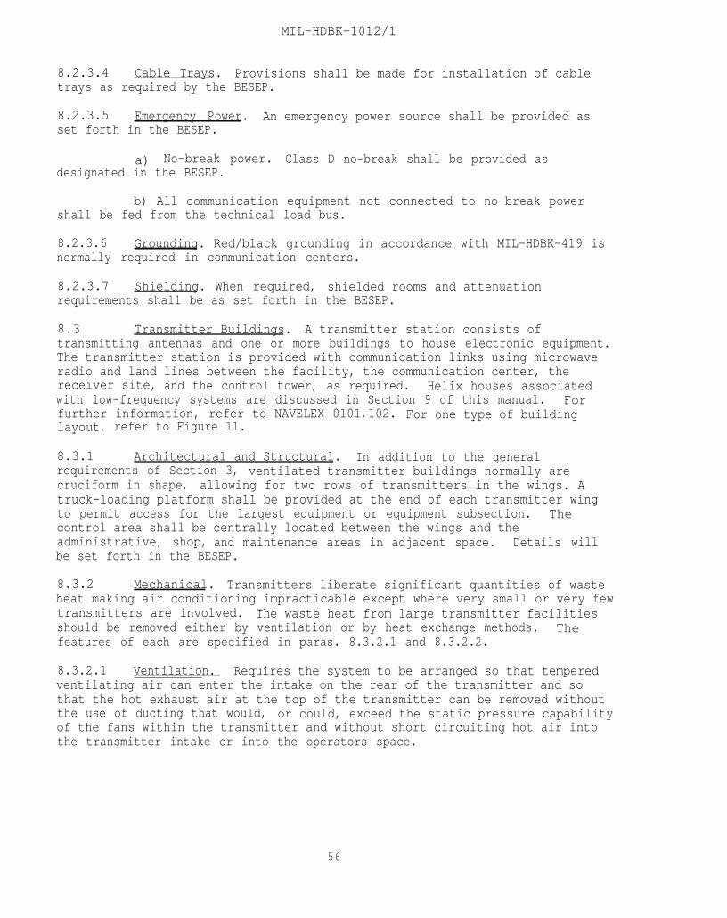
MIL-HDBK-1012/1
8.2.3.4 Cable Trays. Provisions shall be made for installation of cabletrays as required by the BESEP.
8.2.3.5 Emergency Power. An emergency power source shall be provided asset forth in the BESEP.
a) No-break power. Class D no-break shall be provided asdesignated in the BESEP.
b) All communication equipment not connected to no-break powershall be fed from the technical load bus.
8.2.3.6 Grounding. Red/black grounding in accordance with MIL-HDBK-419 isnormally required in communication centers.
8.2.3.7 Shielding. When required, shielded rooms and attenuationrequirements shall be as set forth in the BESEP.
8.3 Transmitter Buildings. A transmitter station consists oftransmitting antennas and one or more buildings to house electronic equipment.The transmitter station is provided with communication links using microwaveradio and land lines between the facility, the communication center, thereceiver site, and the control tower, as required. Helix houses associatedwith low-frequency systems are discussed in Section 9 of this manual. Forfurther information, refer to NAVELEX 0101,102. For one type of buildinglayout, refer to Figure 11.
8.3.1 Architectural and Structural. In addition to the generalrequirements of Section 3, ventilated transmitter buildings normally arecruciform in shape, allowing for two rows of transmitters in the wings. Atruck-loading platform shall be provided at the end of each transmitter wingto permit access for the largest equipment or equipment subsection. Thecontrol area shall be centrally located between the wings and theadministrative, shop, and maintenance areas in adjacent space. Details willbe set forth in the BESEP.
8.3.2 Mechanical. Transmitters liberate significant quantities of wasteheat making air conditioning impracticable except where very small or very fewtransmitters are involved. The waste heat from large transmitter facilitiesshould be removed either by ventilation or by heat exchange methods. Thefeatures of each are specified in paras. 8.3.2.1 and 8.3.2.2.
8.3.2.1 Ventilation. Requires the system to be arranged so that temperedventilating air can enter the intake on the rear of the transmitter and sothat the hot exhaust air at the top of the transmitter can be removed withoutthe use of ducting that would, or could, exceed the static pressure capabilityof the fans within the transmitter and without short circuiting hot air intothe transmitter intake or into the operators space.
56
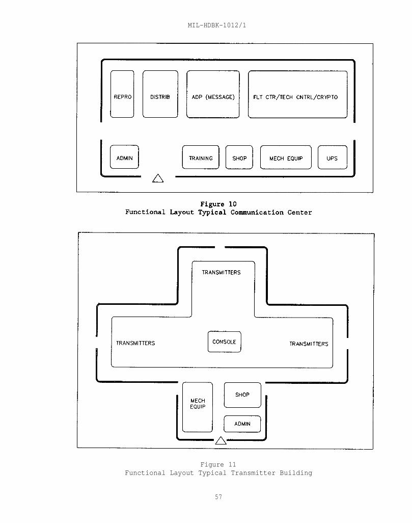
MIL-HDBK-1012/1
Figure 11Functional Layout Typical Transmitter Building
57
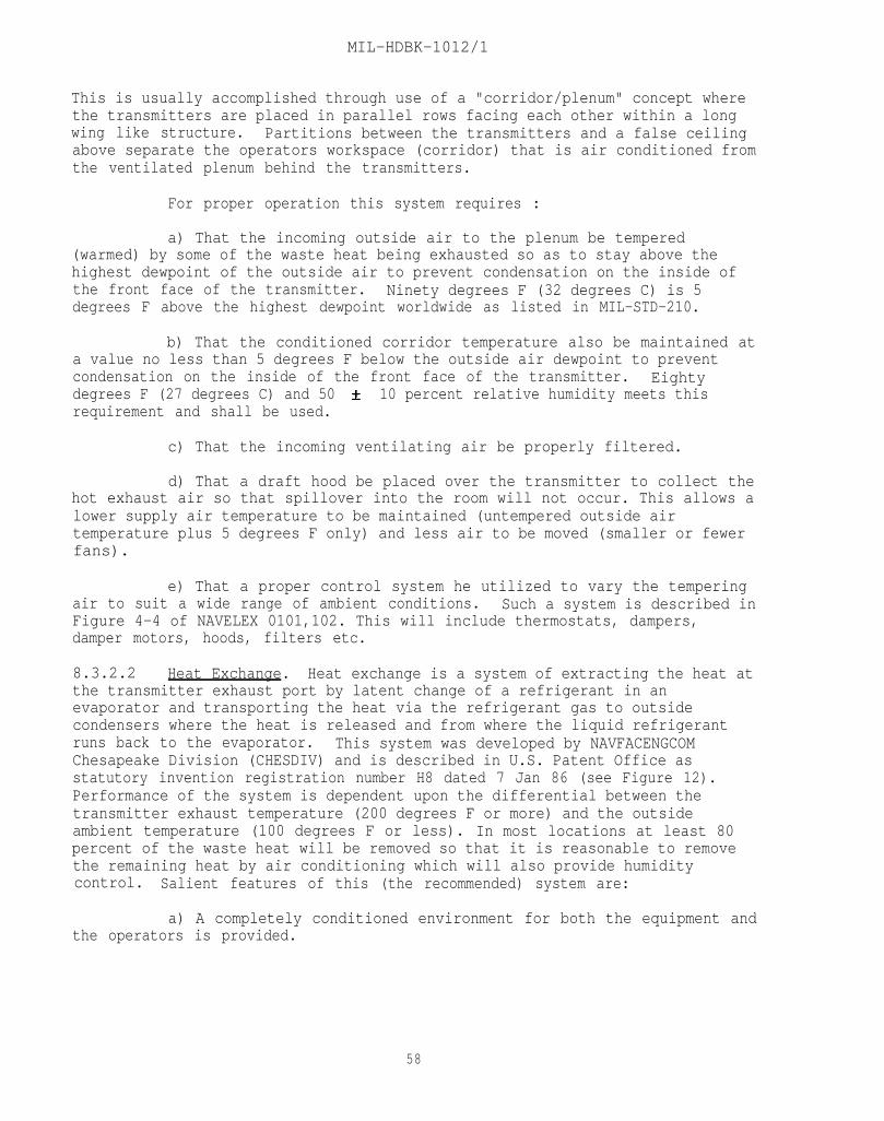
MIL-HDBK-1012/1
This is usually accomplished through use of a "corridor/plenum" concept wherethe transmitters are placed in parallel rows facing each other within a longwing like structure. Partitions between the transmitters and a false ceilingabove separate the operators workspace (corridor) that is air conditioned fromthe ventilated plenum behind the transmitters.
For proper operation this system requires :
a) That the incoming outside air to the plenum be tempered(warmed) by some of the waste heat being exhausted so as to stay above thehighest dewpoint of the outside air to prevent condensation on the inside ofthe front face of the transmitter. Ninety degrees F (32 degrees C) is 5degrees F above the highest dewpoint worldwide as listed in MIL-STD-210.
b) That the conditioned corridor temperature also be maintained ata value no less than 5 degrees F below the outside air dewpoint to preventcondensation on the inside of the front face of the transmitter. Eightydegrees F (27 degrees C) and 50 10 percent relative humidity meets thisrequirement and shall be used.
c) That the incoming ventilating air be properly filtered.
d) That a draft hood be placed over the transmitter to collect thehot exhaust air so that spillover into the room will not occur. This allows alower supply air temperature to be maintained (untempered outside airtemperature plus 5 degrees F only) and less air to be moved (smaller or fewerfans).
e) That a proper control system he utilized to vary the temperingair to suit a wide range of ambient conditions. Such a system is described inFigure 4-4 of NAVELEX 0101,102. This will include thermostats, dampers,damper motors, hoods, filters etc.
8.3.2.2 Heat Exchange. Heat exchange is a system of extracting the heat atthe transmitter exhaust port by latent change of a refrigerant in anevaporator and transporting the heat via the refrigerant gas to outsidecondensers where the heat is released and from where the liquid refrigerantruns back to the evaporator. This system was developed by NAVFACENGCOMChesapeake Division (CHESDIV) and is described in U.S. Patent Office asstatutory invention registration number H8 dated 7 Jan 86 (see Figure 12).Performance of the system is dependent upon the differential between thetransmitter exhaust temperature (200 degrees F or more) and the outsideambient temperature (100 degrees F or less). In most locations at least 80percent of the waste heat will be removed so that it is reasonable to removethe remaining heat by air conditioning which will also provide humiditycontrol. Salient features of this (the recommended) system are:
a) A completely conditioned environment for both the equipment andthe operators is provided.
58
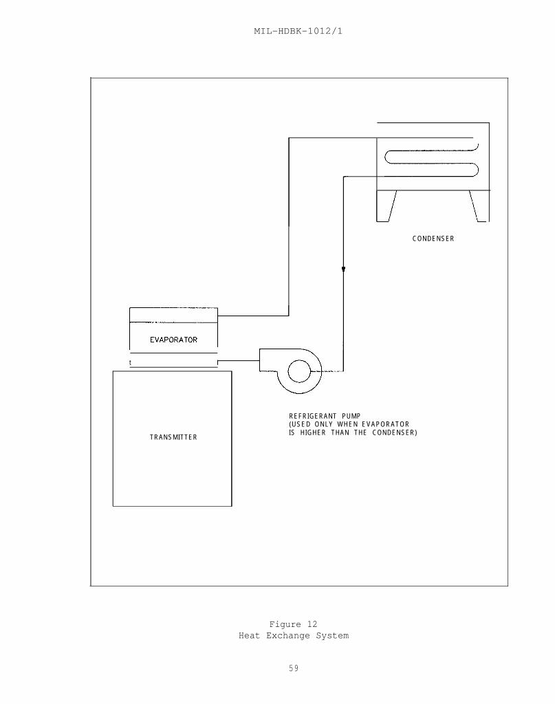
MIL-HDBK-1012/1
TRANSMITTER
CONDENSER
t I
REFRIGERANT PUMP(USED ONLY WHEN EVAPORATORIS HIGHER THAN THE CONDENSER)
Figure 12Heat Exchange System
59
MIL-HDBK-1012/1
b) This system does not require:
(1) A building with long wings (cruciform shape) to permitventilation.
(2) Plenum/corridor partitions and false ceilings.
(3) Walking the length of the corridor through a door and backto obtain access to the rear of the transmitter if adequate transmitterspacing is used.
(4) A large number of outside air filters that must be eitherreplaced periodically at high cost or cleaned which is labor intensive.
(5) A large number of or large size fan for air circulation.
(6) A complicated control system of ducts, dampers diffusers,control motors and sensors.
c) The system will provide controlled heating of the space bysimple thermostatic control of its heat removal capability.
d) Failure of the heat exchange capability (such as loss ofrefrigerant) will not prevent the transmitter from operating.
e) Loss of refrigerant is not hazardous in that it is non-toxic,non-flammable, has a saturated temperature above freezing at atmosphericpressure (will not freeze flesh) and is not a severe solvent. Therefore, losswould not pose a threat to either equipment or personnel.
This system, as noted above, is the recommended method toenvironmentally control transmitter facilities, either large or small.
8.3.3 Electrical
8.3.3.1 Lighting. Fluorescent lighting may be used in all transmitterbuildings except helix houses.
8.3.3.2 Cable Vaults. Cables shall enter the building through a cablevault, either under or above ground.
8.3.3.3 Cabling. Power cables shall be routed through cable trenches.Signal cables shall be run overhead, using cable hangers.
8.3.3.4 Shielding. When specified in the BESEP, the electronic equipmentmaintenance shop will contain a radio-frequency interference screen room. Thescreen room shall have a minimum floor area of 150 ft2 (13.9 and a minimumof 60dB attenuation of electromagnetic radiation from 100 kHz to 100 MHz. Allshielding shall conform to MIL-STD-188/124. Any deviation from theserequirements will be contained in the BESEP.
60
MIL-HDBK-1012/1
8.3.3.5 Disconnects. Safety disconnect switches shall be provided at therear of each transmitter power amplifier. Where plenum chambers are used, thedisconnect shall be inside the plenum near the rear of the transmitter.
8.3.3.6 Circuit Breakers. Separate circuit breakers for the exciter ofeach transmitter shall be installed at the technical power panel.
8.3.3.7 No-Break Power. Class D no-break power will normally not beprovided for a transmitter building.
8.3.3.8 Emergency Power. Emergency power normally is required.
8.3.3.9 Grounding Provide secure grounds for equipment, buildings, andall electronic systems in accordance with MIL-STD-188/124 and MIL-HDBK-419.
8.3.3.10 Bonding
a) Transmitters shall be bonded to the equipotential plane via theshortest available route.
b) Metal objects in the building, including structural steel,reinforcing steel, flashing, downspouts, gutters, cable trays, pipes, andventilators, shall be electrically bonded unless otherwise specified in theBESEP.
c) Isolated metal items not exceeding 2 feet (0.61 m) in anydirection may be considered for bonding on a case-by-case basis.
d) Reinforcing steel shall be bonded together at a maximum spacingof 8 feet (1.44 m) on centers or as set forth in the BESEP.
8.4 Receiver Buildings. The receiver station contains a number ofantennas for detecting a variety of radio frequencies from distanttransmitters. Receiver buildings house the radio receivers and relatedelectronic equipment, as well as computers for storing and/or transmittingreceived communications to the communication center via microwave or wirecircuit. For further information, refer to NAVELEX 0101,102. See Figure 13for a typical building layout.
8.4.1 Architectural and Structural. In addition to the requirements ofSection 3, receiver buildings are generally one story, but a second story willbe required when a Naval Security Group department is included. Details willbe set forth in the BESEP.
8.4.2 Mechanical. Computing, receiving, and other electronic equipmenthoused in receiver buildings generally requires close year-round temperatureand humidity control. Refer to Section 4 and the project BESEP for specificrequirements.
8.4.3 Electrical
8.4.3.1 Lighting. Fluorescent lighting may be used in receiver buildingswhen they are equipped with integral radio-frequency interference filters.
61
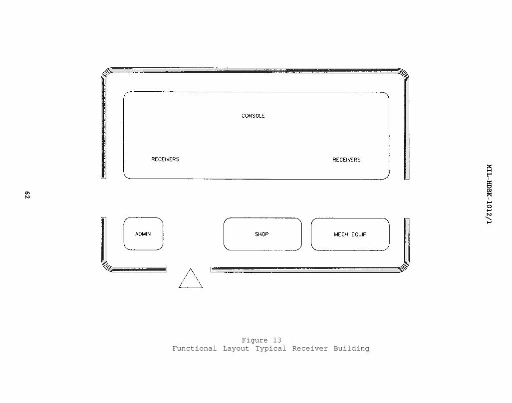
Figure 13Functional Layout Typical Receiver Building
MIL-HDBK-1012/1
The power line filters shall comply with the requirements for conductedelectromagnetic interference of Class A3 equipment, Test CE03.
8.4.3.2 Interference Suppression. All electrical and mechanical equipmentthat generates radio-frequency interference shall be equipped with suppressionand shielding to eliminate such interference.
8.4.3.3 Cable Vaults. Cables shall be brought into the building through acable vault, either above or below ground.
8.4.3.4 Cable Trays. Provisions shall be made for installation of cabletrays as required by the BESEP.
8.4.3.5 Bonding
a) Reinforcing steel shall be bonded together at a maximum spacingof 8 feet (1.44 m) on centers or as set forth in the BESEP.
b) The bonding of metal objects, including structural steel,reinforcing steel, flashing, downspouts, gutters, cable trays, pipes, andventilators, shall be provided only as set forth in the BESEP.
8.4.3.6 Grounding. Grounding shall include the bonding of all groundingelectrodes associated with electric wiring systems, telephone, lightningprotection, and piping systems which enter the building. Refer to MIL-HDBK419 Vol. II, section 1.6.
8.4.3.7 Shielding. The criteria for transmitter facilities shall apply.
8.4.3.8 Emergency Power. Class D & C power is normally required.
8.5 Direction-Finder Facilities. The pusher Direction-Finder (DF) unitdetermines the origin of a high-frequency transmitted radio signal by means ofa cross-fix between two or more DF facilities. Pusher units and other arraysless costly to construct generally will be used in lieu of Wullenweber DFarrays; however, because Wullenweber DF arrays have performance advantagesover the smaller arrays, they may be used where performance is the overridingconsideration.
8.5.1 Architectural and Structural. In addition to the requirements inSection 3, acoustical treatment of NAVSECGRU elements shall provide noiseattenuation within the area to a level commensurate with its use. (See NAVFACDM-1.03) Treatment measures for floors, ceilings, and walls will be specifiedin the BESEP, along with any special requirements.
8.5.2 Mechanical and Electrical. The criteria for radio receiverbuildings are usually applicable. Any deviations will be set forth in theBESEP.
8.6 Command/Control/Intelligence Centers. Command/control/intelligencecenters normally include administrative space, digital computer systems,interactive terminals, graphic display systems, closed-circuit televisionsystems, secure briefing areas, and extensive external and internal
63
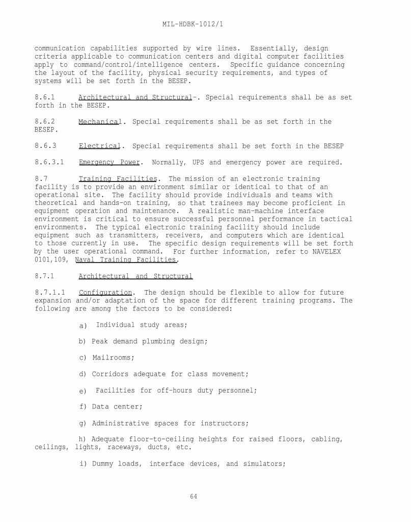
MIL-HDBK-1012/1
communication capabilities supported by wire lines. Essentially, designcriteria applicable to communication centers and digital computer facilitiesapply to command/control/intelligence centers. Specific guidance concerningthe layout of the facility, physical security requirements, and types ofsystems will be set forth in the BESEP.
8.6.1 Architectural and Structural-. Special requirements shall be as setforth in the BESEP.
8.6.2 Mechanical. Special requirements shall be as set forth in theBESEP.
8.6.3 Electrical. Special requirements shall be set forth in the BESEP
8.6.3.1 Emergency Power. Normally, UPS and emergency power are required.
8.7 Training Facilities. The mission of an electronic trainingfacility is to provide an environment similar or identical to that of anoperational site. The facility should provide individuals and teams withtheoretical and hands-on training, so that trainees may become proficient inequipment operation and maintenance. A realistic man-machine interfaceenvironment is critical to ensure successful personnel performance in tacticalenvironments. The typical electronic training facility should includeequipment such as transmitters, receivers, and computers which are identicalto those currently in use. The specific design requirements will be set forthby the user operational command. For further information, refer to NAVELEX0101,109, Naval Training Facilities.
8.7.1 Architectural and Structural
8.7.1.1 Configuration. The design should be flexible to allow for futureexpansion and/or adaptation of the space for different training programs. Thefollowing are among the factors to be considered:
a) Individual study areas;
b) Peak demand plumbing design;
c) Mailrooms;
d) Corridors adequate for class movement;
e) Facilities for off-hours duty personnel;
f) Data center;
g) Administrative spaces for instructors;
h) Adequate floor-to-ceiling heights for raised floors, cabling,ceilings, lights, raceways, ducts, etc.
i) Dummy loads, interface devices, and simulators;
64

MIL-HDBK-1012/1
j) Simulated shipboard environments.
8.7.1.2 Floors. Live loads should be calculated using a realistic estimateof occupancy. Mechanical, telephone, and radio equipment rooms, radioreceiving rooms,, terminal equipment rooms, and equipment-supporting roof areasshould use 150 pounds per square foot (psf).
8.7.1.3 Partitions. Movable and relocatable partitions will be required inall non-bearing applications.
8.7.1.4 Flooring. Raised flooring provides maximum flexibility and shouldbe used in lieu of trenching wherever practical.
8.7.2 Mechanical
8.7.2.1 Electronic Shipboard Equipment. Much of the electronic equipmentinstalled in training facilities is a replica of that used aboard ship.Typically, that equipment is water-cooled rather than air-cooled. The projectBESEP must be consulted for the required information.
8.7.2.2 Non-Shipboard Electronic Equipment. Mechanical requirements fornon-shipboard electronic gear are given in Section 4.
8.7.3 Electrical
8.7.3.1 Power Requirements. In most situations, the determination of powerrequirements is straightforward. Usual power requirements are as follows:
a) Audiovisual remote control devices at lecterns;
b) Banked lighting with door and lectern control centers;
c) Central service cores to serve two or more classrooms;
d) Electrical services located so as not to interfere with movablewalls;
e) Service to accommodate training aids;
f) Open or closed-circuit television systems, including studio andviewing areas.
8.7.3.2 Emergency Power. Unless specified in the authorizing document,emergency and no-break power shall not be provided.
8.7.3.3 Grounding
a) The green-wire grounding system specified in NFPA 70 shall beused in every shore training facility.
b) Consider supplemental grounding accommodations in accordancewith MIL-STD-188/124 and MIL-HDBK-419, as required for each case.
65
MIL-HDBK-1012/1
c) Red/black criteria and methodology shall be as delineated inChapter 12 of NAVELEX 0101,102, and MIL-HDBK-419.
8.7.3.4 Shielding
a) Where there is a great deal of DC signaling, such as incomputer, CIC-mockup, and simulation areas, consider provisions for coaxialcable to prevent signal interaction.
b) Shielded enclosures or rooms lined with foil or mesh shall beused where low-noise and/or low-level devices must be aligned or demonstrated.
8.7.3.5 Electromagnetic Compatibility (EMC). Since the training equipmentmust be capable of operation in various stages of disassembly, the shoretraining facility must compensate for electromagnetic-field retentiondeficiencies in the training equipment.
a) Effective grounding systems for EMC shall be developed asrequired for the individual case.
b) The training-equipment station ground shall be isolated fromall other ground systems in the facility,
c) Each classroom shall have a separate, AWG 4/0 (or larger)insulated ground feeder.
d) Each piece of equipment, sub-assembly, test fixture, and testequipment shall be connected to the station ground feeder. The AC green-wireprotective ground shall not be used as a substitute.
e) Transmitters, exciters, and power amplifiers shall terminate inwell-shielded, impedance-matched dummy loads.
f) The transmission line to each dummy load shall be well shieldedand as short as possible.
8.8 Naval Air Station Control Towers. The primary function of thecontrol tower is to centralize control over aircraft activities, both on theground and in the air, and to promote safe and orderly movement of airtraffic. The Visual Flight Rules (VFR) room is housed at the mostadvantageous position and elevation with respect to the airfields to providecomplete visual control. The tower receives support from the InstrumentFlight Rules (IFR) room, which provides radar contact at distances beyondvisual range and under other than optimal visual conditions. The towerincludes space on various floors for electronic Air Traffic Control (ATC)equipment, in addition to facilities within the tower cab for control andoperation of the equipment. The control tower structure also provides spacefor passageways for interconnecting cables. For further information, refer toNAVELEX 0101,107.
8.8.1 Architectural and Structural. In addition to the generalrequirements of Section 3, the control tower shall conform to the following:
66
MIL-HDBK-1012/1
The standard control tower includes a control room (control cab), electronicequipment rooms, an emergency communication systems, emergency generatorequipment, air conditioning equipment, and sanitary facilities. It is normally a five-story structure, although control towers may contain as manyas ten stories to provide adequate visibility. A height of 43 feet (13.11 m)from the ground to the floor of the control cab is the minimum acceptableelevation. The standard air station control tower is usually an integral partof the operations building. If the control tower is a separate unit, thedesign should allow for future expansion of the operations building. Theground floor area should be large enough to permit easy repair and maintenanceof the emergency generator. The electronic equipment room should be designedto house the emergency communication equipment, voice recorders, the maindistribution frame, and other equipment. The use of FAA standardized designsfor control towers is recommended.
8.8.2 Mechanical. The requirements of Section 4 apply to the mechanicaldesign of control towers, except as follows. Consult the project BESEP foradditional guidance.
a) Remote transmitters and receivers associated with towersgenerally require air conditioning.
b) If remote buildings are associated with the towers, a centralalarm system should be provided for fire, equipment failure, and other out-of-tolerance conditions, such as high temperature.
c) Special fire protection requirements may exist for remotebuildings.
8.8.3 Electrical
8.8.3.1 Power Requirements. The primary power source shall be used duringnormal operating conditions. An automatic-start and switchover emergencygenerator shall be located on the ground floor. Unless an automatic-startgenerator is immediately available, battery-operated equipment is required.
8.8.3.2 Lighting Requirements
a) Ceiling. Ceiling lights shall be recessed so as not to reflectin the windows of the cab.
b) Console. Low-intensity directional lighting shielded from theequipment operator's direct view shall be provided on top of consoles fornighttime operation. The light shall be directed along the planes of theconsole work surfaces with a minimum of window reflections.
c) Floor. Low-level lights shall be provided under consoles fornighttime operation to allow safe movement about the cab without reflections.
d) Intensity control. All lighting for administrative work,operation of controls, and instrument reading shall be compatible withinstalled equipment and shall have adjustable intensity controls.
67

MIL-HDBK-1012/1
8.8.3.3 Alarm Requirements. As a minimum, alarms shall be provided toindicate loss of power, loss of air conditioning, and fire.
8.8.3.4 Cabling
a) Cable vault. Cables shall enter the control tower through acable vault. This area shall be devoted to organizing and routing cablesprior to their entry into the cable shaft.
b) Cable shaft. Power and communication cables from the adjacentbuilding shall pass through a utility duct and enter the cable vault belowgrade. From the cable vault, the cables shall pass through a vertical tunnelcalled a cable shaft. Shaft access off a tower stair landing shall beprovided at least every 15 feet (4.6 m).
c) Junction room. The junction room is the primary access area tothe control cab floor. The control consoles shall open into this space.Power and control cables pertinent to the control cab's function shallconverge here and be terminated or rerouted, and the communication, control,and power feeder ducts shall branch here.
d) Interior wiring. Cable shall be run in the spaces provided bystandard cellular floor construction.
8.8.4 Communications. The quantity and type of communication equipmentwill be set forth in the BESEP. As a minimum, a normal system and anemergency system will be required.
8.8.4.1 Normal Communication System. This system consists of HF andVHF/UHF radio equipment as required by the operational mission of the airstation. This includes any communication control console equipment, ancillaryequipment, and any standby or backup equipment.
a) Standby equipment. Standby radio equipment is tuned to thefrequency of the primary equipment, and any filaments are kept hot, so it canbe put into operation with no warm-up period. Upon failure of the primaryequipment,transfer to the standby equipment is effected instantly by pressinga button on a console.
(b) Backup equipment. Backup equipment may be of the same type asthe primary and standby equipment, but it is not necessarily tuned to the samefrequency, and it is not kept hot.
8.8.4.2 Emergency Communication System. A minimum capability system, usedonly when the normal system is inoperative, keeps the station in limitedoperation by diverting air traffic, landing only aircraft that cannot bediverted to another airfield. This system shall be completely independent ofthe normal system. Control of the emergency communication system shall becompletely independent of normal console control facilities.
8.8.4.3 Grounding. Criteria for transmitter and receiver facilities shallapply.
68
MIL-HDBK-1012/1
8.8.4.4 Suppression. Electronic noise suppression and elimination ofinterference shall be provided as set forth in the BESEP.
8.9 Satellite Communication Ground Stations. A Satellite Communication(SATCOM) ground station transmits and receives Radio Frequency (RF) signals toand from a satellite in a fixed geosynchronous orbit. This system providescommunications for large areas of the world using only one satellite. Atypical SATCOM ground station contains one or more large, rotating, dish-typeantennas equipped with a sensitive RF receiver and transmitter. The siteusually contains buildings and/or transportables to house the RF equipment.For further information, refer to NAVELEX 0101,105, Satellite CommunicationSystem. Figure 14 shows the functional layout of a typical ground station.
8.9.1 Architectural and Structural
8.9.1.1 Configuration. The operations building shall contain an equipmentmaintenance area. The building shall also house emergency generatingequipment and power conditioning equipment. Pad and building layout will beindicated by the BESEP.
8.9.1.2 Antenna Pad. The pad adjacent to the building shall be reinforcedconcrete and shall provide for radome installation when required. Hardstandswill also be required when transportable equipment is provided.
8.9.1.3 Floors. Raised flooring shall be provided for the fixed plant.Flooring systems shall consist of 1-1/2 inch (38.1 mm) stringer widths, andpanels shall be 24 inches (0.61 m) square.
8.9.2 Mechanical. Much of the electronic equipment associated withsatellite communications is provided by the satellite agency. It may differfrom the electronic equipment in other Naval facilities, in that it normallyrequires direct duct connections to the air conditioning equipment instead ofusing room air for cooling. Consult the BESEP for guidance.
Other requirements of Section 4 shall apply to the mechanicaldesign for satellite communication equipment.
8.9.3 Electrical
8.9.3.1 Power Requirements. Primary and secondary power sources may beeither base-generated or commercial, but they shall be separate, reliablesources. Emergency power for use during primary and secondary power outagesshall be provided by means of an emergency generator. No-break power shall beprovided as set forth in the BESEP.
8.9.3.2. Lighting. Fluorescent lighting with approved RF filters may beused in all areas, except inside the radome and in the immediate vicinity ofthe antenna.
69
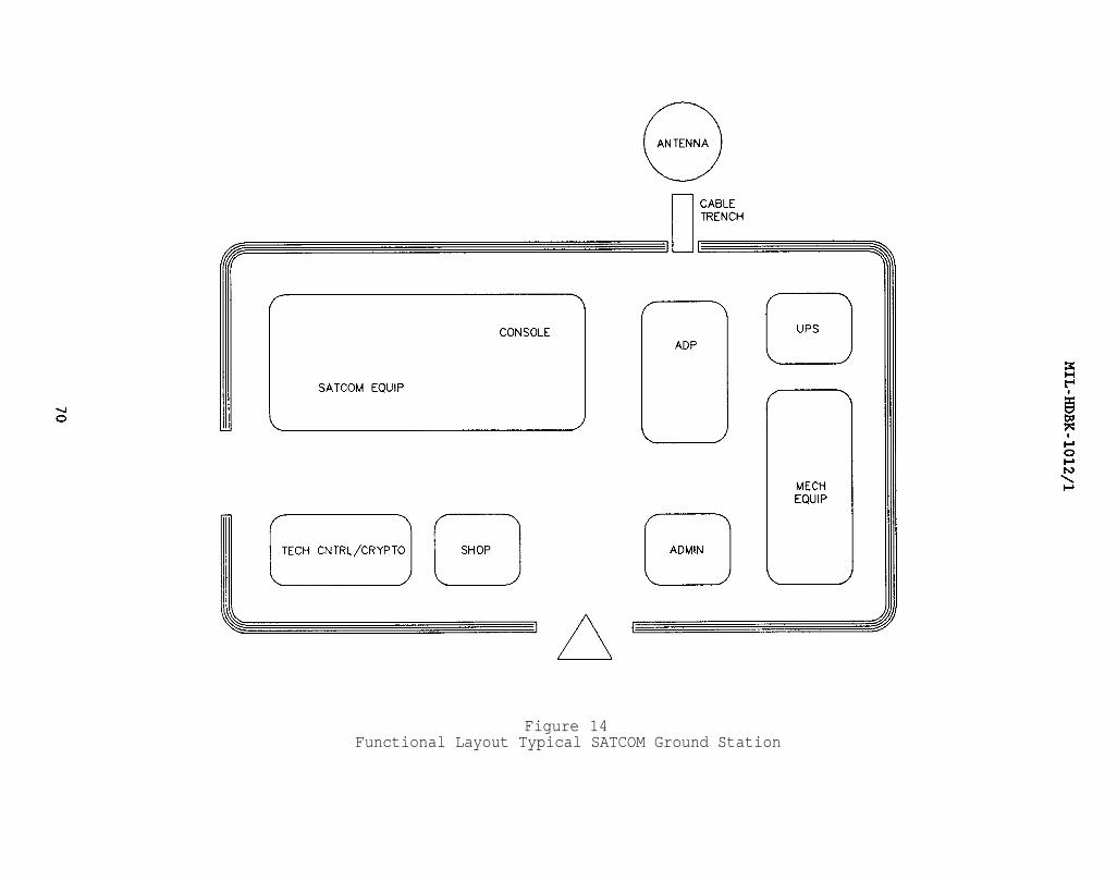
Figure 14Functional Layout Typical SATCOM Ground Station
MIL-HDBK-1012/1
8.9.3.3 Cabling
a) Cabling from the pedestal to the building shall be run in acable trench, as set forth in the BESEP.
b) Transmission and communication lines shall enter the buildingthrough an underground cable vault.
c) Cabling within the building shall be run in overhead cabletrays as set forth in the BESEP.
d) Where red/black security conditions exist, the installationshall conform to MIL-HDBK-419.
8.9.3.4 Interference Suppression. The criteria for receiver facilitiesshall apply.
8.9.3.5 Grounding
a) Hardstands require grounding and shall be part of theequipotential plane specified in the BESEP.
b) Antenna grounding shall be as set forth in the BESEP.
c) Where radomes are required, a properly grounded lightning rodshall be installed at the top of the radome.
d) Where red/black security conditions exist, the installationshall conform to MIL-HDBK-419.
8.10 Transportables
8.10.1 Description. Transportable facilities are electronics equipmentenclosures that range in size and construction from small tactical enclosuresthat can be carried within or towed behind a truck to large semi-permanentenclosures that are essentially assembled and completed in the field. Themain transportable classifications are as follows:
8.10.1.1 Transportable/tactical. This is an enclosure that can betransported by standard military means, quickly placed in operation, andeasily relocated. The electronic equipment must be built in to the greatestextent possible so that the system can be activated by opening protectivedoors/covers and applying power to quick disconnect fittings. Wheels andleveling jacks or skids may be provided.
8.10.1.2 Transportable/relocatable. This is an enclosure that can becompleted, with all equipment installed, checked out, and secured, prior toshipment. The enclosure, if possible, should conform to the dimensions ofInternational Organization for Standardization (ISO) containers, in accordancewith OPNAVINST 4620.8, Use of Internal Containers, Special Purpose Vans. andTactical Shelters. These units require minimal assembly and hook-up in thefield. These transportables are generally much larger and heavier thantactical units, and offer more flexibility. in electronic and environmental
71
MIL-HDBK-1012/1
control system layout and design. The enclosures are usually mounted onleveling jacks or stands, or they may be mounted on a field-constructedfoundation.
Where ISO units cannot be used such as 10 foot wide units, built-intension members in the wall and built-in spreader bars in the roof should beprovided so roof line hoist points can be used at the quarter points of thecontainer. Removable end panels, some with personnel doors, are often timesprovided to simplify the installation and removal of equipment. Flexible(accordion like) weather covers and demountable walkways are used to connectthe transportable either to a building or to other transportables whenapplicable. When stair access is provided allow sufficient platform space atthe top for door swing and so it will not be necessary to back down the stairsto open the door. Railings should meet OSHA 2201, Safety Standards forGeneral Industry.
8.10.1.3 Transportable/non-relocatable. With this type of enclosure, thereis little or no emphasis on relocatability. Shipment may include any numberof packages, which are field-assembled and installed. Factory fabrication andpre-assembly are usually limited to providing several large portions of theenclosure or complex, along with some portions of the power wiring, plumbing,and air conditioning. The enclosures are usually mounted on field-suppliedfoundations or supports.
8.10.1.4 Sub-categories. Various sub-categories of transportables includetrailers, semi-trailers, vans, milvans, containers, and shelters. These aregenerally in the tactical or relocatable category, but, in certainapplications, could be classified as non-relocatable. Containers are ISOstandard-sized units. Two are of particular interest for housing andtransporting Naval electronic equipment; both are 8 feet (2.4 m) wide by 8.5feet (2.6 m) high, and are either 20 feet (6.1 m) or 40 feet (12.2 m) inlength. These units are designed for a gross weight of 44,800 pounds (20 317kg) and 67,200 pounds (30,475 kg), respectively, and are provided with ruggedcorner fittings for hoisting, stacking, and shipping. Milvans (the Armyequivalent of ISO containers) are only available in the 20-foot (6.1 m)version. Shelters are tactical units and rarely exceed 7 feet (2.1 m) wide by7 feet (2.1 m) high by 12 feet (3.7 m) long. Trailer, semi-trailer, and vandimensions depend on the particular vehicle selected for use. For furtherinformation, refer to NAVELEX 0101,110, Installation Standards and Practices.Figure 15 shows a typical transportable installation.
8.10.2 Architectural and Structural
8.10.2.1 Structural Requirements. Transportable facilities shall bedesigned to withstand equipment weights and other in-service loads, plus anyload resulting from storage, handling, and transportation. Where possible,the design should incorporate the longeron/stressed skin (semi-monocoque)concept. This permits maximum interior space with respect to outsidedimensions, but limits the size and location of openings and requires carefuldesign of framing around opening. (In extreme cases, an entire wall or endmay be open where one container is coupled to another, and it may be necessaryto use shipping panels that provide structural support at the openings whenthe containers are in transit.)
72

Figure 15Typical Transportable Installation
MIL-HDBK-1012/1
a) Strength, weight, corrosion resistance, shielding, Radio-Frequency Interference (RFI) attenuation, equipment mounting requirements,fire criteria, and compatibility of dissimilar metals shall be considered whenselecting frame and skin materials. Container framing may be formed, rolled,or extruded sections of aluminum or steel. Interior and exterior skins areoften of aluminum since it is lightweight and corrosion-resistant and providesa significant amount of RFI protection even if RFI gasketing and cut-off coresare not provided. Any of several plastics may be used as a skin material forapplications such as radar windows; steel may be used if adequate finishes areapplied.
b) Flooring shall be aluminum plate or plywood-metal lamination,so that metal surface is exposed top and bottom. Vinyl tile is typicallyadded to the top surface.
c) Between interior and exterior wall skins, a thermal barrier,such as wood or thermosetting plastic laminate conforming to NationalElectrical Manufacturers Association (NEMA) Grade L or LE, is required. Anyremaining space in the wall shall be filled with fiberglass or polyurethaneinsulation.
d) Roof construction shall be similar to wall construction, exceptthat the exterior skin shall be a single sheet of aluminum alloy laminated toa hardboard backing to resist stresses from personnel walking on the roof, aswell as transportation-related stresses. The laminating adhesive shall beflexible to allow for thermal expansion of the roof sheet.
8.10.2.2 Weather Resistance. Exterior surfaces of the container shall be asairtight and watertight as possible. Water vapor passing through any openingor non-vaporproof barrier in the outer shell will condense in the insulationor in cavities in the insulation space. As a result, the thermal conductivityof the insulation may be much higher than its original value, so that requiredinterior conditions are not achieved or a much greater load is placed on theequipment.
a) Some moisture may enter the space by diffusion through cracksor permeable surfaces. The major amount, however, is brought in byinfiltration.
Because of the difficulty of making the outer skin completely leakproof,additional protection is necessary. Three methods are possible:
(1) using foamed-in-place plastic insulation,
(2) lining the inside of the exterior skin with a non-permeable vapor barrier, such as aluminum foil, coated with a plastic binderthat can be sealed at the joints, or
(3) coating the interior surface of the exterior skin withvapor-sealing compound. Care in installation is important, especially aroundwiring, piping, and framing. The use of the first method is encouraged.
74
MIL-HDBK-1012/1
b) The interior skin should be as vaportight as practicable. Itmust be water-resistant so that cleaning does not readily soak the insulation.
c) All doors shall fit properly and shall be gasketed to minimizeair and heat leakage. Hardware for doors shall withstand the severeconditions that may be encountered.
8.10.2.3 Finishes. Floor surfaces shall be of wood or metal. If floors arewood, they shall be metal-faced plywood with the edges well sealed againstwater penetration. Metal floors shall be watertight. Floors shall be coveredwith vinyl tile for ease of cleaning. Metal-faced plywood, aluminum, certainplastics, and other materials are suitable for interior wall surfaces. Unlessthe exposed surface is metallic, the material shall have a flame spreadclassification not greater than 22.8 or a smoke developed rating not greaterthan 50, in accordance with UL Standard 723-1983, Test for Surface BurningCharacteristics of Building Materials. Glass-reinforced plastic materialshave been used for interior and exterior wall surfaces and, commercially,several manufacturers now produce all-plastic containers. Where there is aneed for radar transparency, a thermosetting plastic exterior panel may beused, provided it is painted to match the surrounding surfaces with specialradar-transparent paint. Where walls must be used to support equipment forother loads, vinylized metal-clad plywood should be considered. These panelsare metal-clad on both sides but vinylized on the interior exposed side only.
8.10.2.4 Equipment Layout. Equipment layout shall be as specified in theBESEP.
8.10.3 Mechanical. The general requirements of section 4 apply to thedesign of transportables. Deviations and additional requirements are listedbelow.
8.10.3.1 Tactical Transportables. Tactical transportables impose severelimitations on the mechanical equipment.
a) Air Conditioning. Air conditioning equipment must be small andrugged. Generally customized, direct-expansion, air-cooled, through-wallunits using refrigerant R12 are provided, even though size and weightlimitations make them inefficient and expensive in comparison with standardcommercial units. Refrigerant R12 is preferred to R22 because of the highinternal pressure generated by R22 at storage temperatures encountered duringtransportation. Also, commercial units normally are rated at 90 degrees F (32degrees C) dry bulb and 75 degrees F (24 degrees C) wet bulb. These factorspreclude the use of most small commercial units currently available.
b) Backup Air Conditioning. Each unit shall be equipped with twoincrements of cooling, each sized for half the design load; a third incrementshall be provided for the evaporator coil strictly for use as standby. Thisrequires a special evaporator coil circuited to achieve proper load balancewith any two increments operating.
c) Heating. Normally, electric strip heaters are provided withthe air conditioning units and mounted downstream of the evaporator coil.Heaters may be used for dehumidification,, but should be controlled not to
75
MIL-HDBK-1012/1
operate whenever there is a full cooling load. Provisions for backup heat arenot required.
8.10.3.2 Relocatable and Non-Relocatable Transportables. Relocatable andnon-relocatable transportables more closely resemble permanent facilities thantactical ones. Therefore, mechanical design is not as restricted, and thegeneral guidelines listed in Section 4 are more appropriate.
a) Air Conditioning. Tactical types air conditioners areinappropriate for this class of transportables, but R12 refrigerant should beused, since refrigerant storage pressures during transportation would beexcessive with R22. Various types of systems may be used, including splitsystems with remote DX condensers, commercial-quality single package DX units,and chilled-water systems with air-cooled chillers. Chilled water systems areapplicable to groups to transportables, especially if they are non-relocatable.
b) Backup Air Conditioning. This is required for any functionspecified as critical in the project BESEP. Special circuiting of coils isnot required. It is recommended that units be incremented to handle only aportion of the load, with an extra unit used for backup.
c) Heating. Normally, the heat load is minimal and heat requiredto maintain space conditions should be provided as part of the airconditioning unit. Electric resistance heating is preferred because of itssimplicity and reliability. Backup heating is not required.
8.10.4 Electrical. In most cases, the requirements for transportables aresimilar to those for transmitter and receiver buildings. In all cases,installation shall be in accordance with NFPA 70.
8.10.4.1 Conductors
a) Stranded Conductor. Stranded cable shall be used wheneverpossible. The use of stranded conductor is mandatory for all power wiring.
b) Solid Conductor. In non-power applications where solidconductor must be used, the conductor shall be securely anchored along theentire run, and sufficient slack shall be incorporated at termination pointsto compensate for in-transit motion.
8.10.4.2 Conductor Installation
a) Maintainability and future expansion requirements are primedesign considerations.
b) Cabling and wiring shall be installed to permit circuitchecking or circuit renewal without removing major pieces of equipment.Planned wiring and preformed harnesses shall be incorporated whereverpossible.
c) Wires and cables shall be situated to minimize inductive andcapacitive effects.
76

MIL-HDBK-1012/1
d) Connector plugs and receptacles shall be positioned tofacilitate rapid connection and disconnection of major items.
e) Wire and cables shall be long enough to allow otherwiseinaccessible equipment to be removed for service without disconnection.
f) Conductors shall have sufficient clearance from high-heat-radiating components.
g) The minimum bending radius shall not be violated in any case.
8.10.4.3 Metallic Ducts
a) Ducting is the preferred method of running cable.
b) Under-floor areas shall be used for cabling only if the under-floor structure is specially designed for this purpose.
c) Conduit shall be used where penetration of walls, floors, orroofs is necessary.
8.10.4.4 Conductor Terminations
a) Terminal Boards; Wires and cables shall be arranged onterminal boards to minimize inductive and capacitive effects.
b) Distribution Frames. All cables, except antenna cable carryinginformation to or from equipment, cabinets, or containers, shall terminate ata distribution frame or junction box. Audio and control circuit terminationsshall be separate to minimize interference.
c) Terminations. Terminals that grip the wire insulation shall beused. To facilitate equipment removal, quick-disconnect cable terminationsare desirable.
d) Insulation Protection. Textile and glass-insulated ends ofwire shall be secured against fraying by mechanical means or by applyingvarnish conforming to military specifications.
e) Strain Relief. Strain relief shall be provided such that, whenportable cables are plugged into container-mounted connectors, the weight ofthe cable does not hang on the connector.
f) Service Loops. Sufficient slack shall be left in conductors tomake at least two additional terminations.
g) Spare Conductor Runs. Ten percent spares shall be available sothat conductors may be replaced without having to run new cables. Sparesshall be long enough to reach the remote terminal within the cabinet orequipment; they shall be folded back and laced until used.
77
MIL-HDBK-1012/1
h) Antenna Cables. Where control and signal cables leading toantennas penetrate the roof of a van or other similar transportable, asuitable protective cover shall be provided.
8.10.4.5 Power Requirements
a) Primary Power. Relocatable and non-relocatable installationsshall be designed to operate on commercial power or generator power, with thedetermining factors being the availability, accessibility, and reliability ofcommercial power at the site. Tactical installations usually require portablegenerators.
b) Emergency Power. The need for emergency power shall beconsidered for each case.
c) Power Connections. The installation of power connections fortransportable installations is NAVFAC's responsibility.
8.10.4.6 Lighting. The primary lighting system shall be designed to operateoff the primary power source. Battery-operated emergency lighting shall beprovided for use during primary power outages.
8.10.4.7 Bonding. The criteria governing permanent electronic facilitiesare applicable to the design of transportables. Specific requirementsinclude:
a) Direct Bonds. Soldering and welding are the preferred methods.Where semi-permanent bolted bonds are required, lock washers of the internal-external type shall be used.
b) Indirect Bonds. Low-inductance bonding straps shall be used.The strap ends shall be brazed or silver-soldered to the ground bus orterminal. The connections to the equipment or cabinets shall be bolted andshall have a measured resistance of 0.01 ohms or less.
8.10.4.8 Grounding. The criteria governing permanent electronic facilitiesare applicable to the design of transportables. Specific requirementsinclude:
a) Relocatable and non-relocatable. Grounding techniques shall beof the more permanent type, since the facility, one installed, will operatefor an indefinite period. If the facility is moved, the grounding systemessentially will be abandoned in place.
b) Tactical. The ground system shall be designed such that thefacility is capable of carrying the majority of its ground rods andinterconnecting cables.
c) Responsibilities. The grounding facilities at installationswhere transportable configurations are used shall be designed by NAVFAC andinstalled by Public Works or contractor personnel responsible for constructingentire facility. The electronic equipment installer shall tie into the groundstub with a short connection from the container.
78
MIL-HDBK-1012/1
8.10.4.9 Shielding. Shielding shall be used as required for the individualcase. Where shielding is used, the criteria governing permanent electronicfacilities shall be observed.
8.11 Automatic Data Processing Centers. The automatic data processing(ADP) center provides computer-oriented information processing and displaysystems. The ADP center support all Naval Shore systems and assigned shipsystems in all matters requiring digital, stored-program computers. Inaddition to computers, the ADP center contains the peripheral devices requiredto form a complete system. Its functions include processing, displaying, andtransmitting data for data collection, data distribution, inquiry processing,computer time-sharing, and message switching. Details of system needs will beset forth in a BESEP, or by the user command. For further information, referto NAVELEX 0101,111, Digital Computer Systems. Vol I of II.
8.11.1 Architectural and Structural. In addition to the generalrequirements of Section 3, data processing facilities shall comply with thefollowing:
8.11.1.1 Configuration. In addition to the computer room, the dataprocessing center shall include a data storage room a data base office, atape/disk library, keypunch room office space, and a production control room.The design should provide for future expansion.
8.11.1.2 Floors. Raised floors shall be used in computer areas.
8.11.2 Mechanical. Basic design criteria are provided in Section 4. Thecriteria in this paragraph are directed toward larger computer facilitiesclassified as data processing centers. Although the criteria primarily applyto areas housing the computing equipment, ancillary spaces, including storageareas for magnetic disks and tapes, punch cards, and paper require similarenvironmental control. Tolerances for ancillary areas are wider, however, andenvironmental control system reliability is not as critical.
8.11.2.1 Design Criteria. Most manufacturers recommend that the computersuse room air for cooling. Normally, a room condition of 72 2 degrees F(22.2 1 degrees C) and 45 5 percent RH is provided where thelatent/sensible ratio of the load requirement matches that of the coilperformance giving the optimum economic performance. Some manufacturers,however, require that cooling air be introduced directly to the machine.Generally, this requires a supply air temperature of about 65 degrees F (18degrees C) and a relative humidity of 40 to 65 percent to avoid condensationwithin the equipment. This will in turn require that reheat tempering of thesupply air is necessary. This can double the required cooling capacity,unless waste heat is used for the purpose and is not a recommended design.
8.11.2.2 Cooling Loads. Information on the heat release of the computingequipment must be obtained from the BESEP or from the computer manufacturer.Because of the relatively low occupancy and the small percentage of outsideair, heat gains in computer rooms are almost entirely sensible. As a resultof this and the low room design conditions, the air circulation rate per tonof cooling normally must be higher than the circulation rate for comfortcooling. The high rate of heat release from computer results in a high load
79
MIL-HDBK-1012/1
density, yielding ratios of 50 to 75 square feet per ton of cooling. Computerareas are therefore susceptible to drafts if care is not taken in the layoutof supply registers and diffusers. Hot spots can also occur because of theconcentrated loads.
8.11.2.3 Air Conditioning Systems. Systems serving data processing centersshould be independent of other systems in the building if the building centralsystem is secured during the winter season. Chilled water systems may becross-connected to provide backup. The air conditioning systems available foruse are listed in Section 4. They may be classified as self-contained units(using air or water for condensing), decentralized air-handling equipment, andcentral systems.
a) Self-contained Units. Units are completely packaged, withreciprocating compressors and refrigerant coil, filters, humidifiers,provisions for a reheat coil, operating controls, and instrumentation such assignal lights, dirty filter alarms, and other status/alarm lights.Construction of major items should be corrosion-resistant. Units can bearranged to supply air down into a floor plenum or up to overhead ducts and/ora plenum with diffusers. The units are located in the spaces served, and areprovided with water-cooled condensers connected to a remote cooling tower,water-to-air heat exchanger, or other heat rejection device. Multiple unitsare usually provided, and the outdoor ventilation air is normally introducedthrough one of them.
b) Decentralized Air-handling Units. These are similar to self-contained units, but are served by remotely located refrigerationequipment, usually through chilled water coil connections. This arrangementis appropriate in facilities where both air-cooled computing equipment andwater-cooled equipment (such as computers associated with simulators) isinstalled. Chilled water normally should be in the range of 47 to 50 degreesF (8.3 to 9.4 degrees C) to provide the high sensible cooling ration requiredin computer areas. This type of system requires central chiller equipmentcapable of 24- hour-per-day, year-round operation.
c) Central Systems. These have an advantage in that no computerroom floor space is taken up by the air-handling units, and all servicing andmaintenance takes place outside the computer rooms. Central systems must bedesigned, however, to accommodate future expansion of the computer space orchanges in loads, and are not as widely used as the other systems.
8.11.2.4 Supply Air Distribution.distribution is important in all centers impose even more stringentand future expansion, with minimalUnder-floor or ceiling plenum suppflexibility.
As indicated in Section 4, airelectronic equipment areas. Data processingrequirements to accommodate load changeschanges to the mechanical equipment.ly is commonly used to provide the required
a) Under-floor Systems. Where raised floors are provided, it isoften advantageous to use them as a supply plenum for conditioned air. If airmust be introduced directly to the machine, more stringent restrictions areimposed on allowable temperature and relative humidity than if it wereintroduced to the room; this approach should therefore be used only if
80
MIL-HDBK-1012/1
required by the equipment. When the plenum supplies air to the room,relocatable floor panels with registers or perforated flush panels are used.The perforated panels are suitable for high-traffic areas and may be locatedclose to the equipment, since they produce a high degree of mixing with room air. Floor registers are not flush and should not be located in areas ofheavy traffic or where wheeled carts are expected to operate. They arecapable of longer throw and better directional control and may be appropriatefor use in certain locations.
b) Above-ceiling Systems. Overhead supply systems through ceilingplenums with perforated panels as diffusers are occasionally used for computerrooms. This can cause hot spots in high-load areas, however, and generally isnot as flexible as diffuser grille distribution. An advantage of ceilingsystems is that they do not collect dirt from the floor area. Best conditionsare usually achieved by distribution ductwork, with the air discharged intothe space through diffusers in the ceiling. Perforated ceiling tiles areusually inadequate as air outlets for final distribution to a computer room,since they normally are incapable of handling the large quantities of airrequired in these applications.
Return air may also be ducted from ceiling-mounted return airregisters in an overhead system. Short-circuiting between supply and returnmay occur if care is not exercised in locating the supply and returnterminals. Overhead ducted supply usually serves normal building loads forlights, occupancy, and the structure, while under-floor systems normally serveto augment the central system in removing heat from the computers. Either canbe used, but both may create drafts, especially when ceilings are low. Withboth systems, provisions must be made to maintain room relative humidity.
8.11.2.5 Computer Equipment Cooling. Some computer equipment requiresdistilled water for cooling. This requirement will be indicated in the BESEP.Normally, when this requirement exists, the cooling system is provided by themanufacturer as part of the computer equipment, and is connected to a heatexchanger, which in turn can be connected to the chilled-water systems as afinal heat sink. Chiller water piping, therefore, is often required in thecomputer room. Careful installation of the piping and proper insulation,where necessary, should minimize the possibility of leaks and condensation. Aseparate refrigeration system for the computer equipment is desirable becauseof the need for continuous year-round operation, the need for higherreliability than with comfort applications, and the need for some components(in critical applications) to be on the UPS circuit. Heavy loads such aschillers or compressors are never to be placed on the UPS output circuit.Some installations require the chilled water system to be sized for growth sothat it can be expanded to accommodate future additions to the data processingcenter.
8.11.2.6 Condensing Methods. In some locations, cooling towers may beacceptable; in others, the need for winterization and excessive watertreatment may preclude their use. Air-cooled refrigeration condensers withhead pressure controls and separate hot gas and liquid lines for each,refrigeration circuit are widely used. In installations where multiplerefrigeration systems are involved and/or the units are remote from the pointof heat rejection, air-cooled heat exchanger systems tend to simplify the
81

MIL-HDBK-1012/1
piping and controls. Glycol-loop exchangers (or water-loop exchangers inclimates not subject to freezing) permit use of a closed water systemconnected to the condenser and facilitate compressor head pressure control bypressure-actuated water regulators at the condenser.
8.11.2.7 Instrumentation. Most automatic data processing centers requireroom temperature/humidity recording devices. Alarms should be incorporatedwith the recorders to signal if temperature or humidity is too high or twolow. In large rooms, recorders should be installed in each zone. Whenchiller water is supplied directly to the computer, records of chilled waterinlet and outlet temperatures and pressures should be maintained. Sensingdevices to indicate the presence of water in the computer room under-floorcavity are desirable if chilled water piping is installed in the cavity. Allmonitoring and alarm devices should provide local indication, and, if acentral monitoring and control point exists, the alarms should be transmittedto that location.
8.11.2.8 Fire Protection. As a minimum, smoke detectors should be providedin both the room and the air conditioned air stream. Under raised floors,these devices should be provided in the cavity, regardless of whether it isused as a plenum, when electrical cabling is installed, The fire protectionsystem should include a controlled and properly sequenced shutdown of computerpower, either manual or automatic, depending on its criticality and thepotential for false alarms. Refer to MIL-HDBK-1008 for additional guidance.
8.11.3 Electrical
8.11.3.1 Lighting
a) Fixtures. Lighting fixtures shall be recessed within theceiling where possible. Fixtures extendinginterfere with equipment installation.
below the ceiling shall not
b) Sunlight. Direct sunlight shall not interfere with the lowlevels of illumination needed for visibility of the console and signal lamps.
c) Control. Lights for general illumination shall be sectionallycontrolled by switches so that portions of the lighting can be turned off asdesired.
d) Emergency Lights. Emergency lighting shall be provided asrequired by NFPA 101, Code for Safety to Life from Fire in Buildings andStructures. The lighting shall be adequate to light the computer area whengeneral illumination is off. In transportables, provisions shall be made tokeep emergency lights from operating during shipment.
8.11.3.2 Power Requirements. Design shall conform to Article 645 ofNFPA 70.
a) Equipment Power. The designer shall comply with the powerrequirements and characteristics peculiar to each piece of computer equipment.The information will be supplied by the BESEP or the user command.
82
MIL-HDBK-1012/1
b) Secure Power. Power used to supply equipment that processesred information may require special service to ensure security. The BESEPwill set forth all such requirements.
c) Frequency Conversion. Where frequency conversion is required,either a motor generator or static converter shall be used. Motor generatorsshall be located in a room separate from computer equipment. Staticconverters can be located in the computer room if they are adequately groundedto prevent EMI. Situations where two converters are required will beindicated in the BESEP.
d) Emergency Power. Class C auxiliary power, when required, willbe specified in the BESEP.
e) No-break Power. Class D auxiliary power is normally requiredand shall be as set forth in the BESEP.
f) Convenience Outlets. Convenience outlets in ADP equipmentunits shall be run off the technical bus. Additional outlets shall beprovided at 12 to 14 foot (3.66 to 4.27 m) intervals around the perimeter ofthe room. These outlets shall be run off the non-technical bus.
8.11.3.3 Power Distribution
a) Bus Configuration. Power shall be distributed in a split bussystem, with one bus serving the technical load and one bus serving the non-technical load.
b) Technical Bus. The technical bus shall serve the computerequipment and minimal lighting.
c) Non-technical Bus. The non-technical bus shall serve all otherpower requirements.
8.11.3.4 Power Control
a) Main Disconnect. The "emergency off" switch shall be as closeto the main exit as possible.
b) Emergency Power Monitoring System Controls. When an emergencypower system is required, a facility monitoring panel shall be provided in thecomputer room and electrical equipment room. The panel shall indicate whenemergency power is in use (emergency power on), sound an alarm with a manualshut-off feature (emergency power alarm), and provide telephone communicationbetween the computer room and the alternate power supply.
8.11.3.5 Grounding
a) Equipment Protection. Equipment shall be grounded inaccordance with manufacturer's specification and comply with MIL-STD-188/124and MIL-HDBK-419.
83
MIL-HDBK-1012/1
b) HEMP Protection. When such protection is required, thecriteria will be found in MIL-HDBK-1012/2 and the BESEP.
8.11.3.6 Bonding. Bonds between cabinet chassis and the raised floor shallnot exceed a design goal specified resistance of 5 milliohms.
8.11.3.7 Shielding
a) Shielding shall be provided as needed for each case.
b) Shielding for red information areas shall be as set forth inthe BESEP.
8.12 Oceanographic Facilities. Oceanographic Centers process signalsfrom underwater areas via submarine cables (commonly referred to as seacables) to a shore processing facility. The shore equipment is normallylocated in a Terminal Equipment (TE) building. Specific guidance concerningthe layout of the facility, physical security requirements, and types ofsystems will be set forth in the BESEP. The TE building may also containadministrative offices and electronic power generation equipment.
8.12.1 Architectural and Structural. The facility shall comply with thegeneral requirements of Section 3. Special requirements shall be as set forthin the BESEP.
8.12.2 Mechanical. Basic design criteria are provided in Section 4.Special requirements shall be as set forth in the BESEP.
8.12.3 Electrical
8.12.3.1 Underwater Cable. Typically, one or more buried cables run fromthe sea to the TE building. The signals on these cables are extremelysensitive to interference from nearby AC power circuits and strong RF fields.No electric conductors, equipment, facilities or structures of any kind shallbe installed in the vicinity of these cables. A set of guidelines forinstallations in the vicinity of underwater cables is given below. Writtenpermission from the SPAWAR (PMW-180) is required, on a case-by-case basis, togrant waivers from these guidelines.
8.12.3.2 Quiet Zones. Quiet zones for a typical site are defined inFigure 16.
a) Quiet Zone A shall be kept completely free of AC powercircuits.
b) No structures or facilities of any kind shall be installed inQuiet Zone B except as specifically noted below. This restrictionspecifically includes antennas of any kind, overhead or buried communicationlines, and AC power lines.
(1) AC-powered security lights may be installed in Quiet ZoneB provided they are designed to prevent the injection of power-line frequencycurrents into the earth in the quiet zone. Isolation transformers and ground
84

MIL-HDBK-1012/1
85

MIL-HDBK-1012/1
fault current interrupters are required for security lights in the Quiet Zone.Safety ground leads associated with these circuits must not be connected tolocal earth grounds at individual fixtures. Non-conducting supports arerecommended. If conducting supports are used, individual isolationtransformers are required at each fixture to isolate safety and local grounds.
(2) Electrical security devices, energized entirely fromremote direct current sources, may be used in Quiet Zone B provided they arenot grounded to local grounds within the quiet zone.
(3) Guy wires terminated in Quiet Zone B are required to haveat least one insulator in each individual wire.
(4) A three dimensional clearance of at least 25 feet must bemaintained between the sea cable and any current-carrying conductors installedin Quiet Zone B. Conductors crossing the cable path must be routed at rightangles to the cable for at least 25 feet on each side. Conductor pathsparallel to the cable shall be avoided. Any such conductors are required tohave two adjacent return conductors in the same cable arranged so as to cancelmagnetic fields. Overhead installations are preferable to buriedinstallations anywhere in the quiet zone.
(5) Security fences within Quiet Zone B are required to begrounded and bonded as specified in para. 5.5.3.3. Fences crossing the cablepath must run at right angles to the cable for a distance of at least 25 feeton each side of the cable. Care shall be exercised in placing fence posts onany similar structures requiring excavation in quiet zones A or B.
8.12.3.3 Grounding. Special grounding plans, tailored to each site, arerequired for oceanographic facilities and will be included in the BESEP whereappropriate. Complete isolation of signal, safety, and neutral grounds isrequired except at specifically designated points.
a) All sites have main ground identified as the G2 ground. Inaddition, some sites have special grounds (G1 and G3) which are directlyassociated with underwater cables and are installed and maintained byunderwater cable installation organizations. G2 grounds normally consist ofmultiple driven electrodes with a measured resistance of less than one ohm.G2 ground field construction details are included in the BESEP whereappropriate.
b) The G2 ground field is connected to a main G2 ground plate by asingle, large (typically 750,000 circular mils) conductor. No otherconnections to this ground field are authorized without specific writtenpermission from SPAWAR (PMW 180).
c) The main G2 ground plate is connected to a number of branchground plates dedicated to individual subsystems. One branch ground plate isdedicated to safety grounds, building frame grounds, and power circuit neutralground connections. Other branches are connected to specific subsystems asspecified in the BESEP. These grounding systems are in accordance with Volume2, para. 1.4.3 of MIL-HDBK-419 and NFPA 70, Article 250.
86

MIL-HDBK-1012/1
d) The neutral conductors for all supplementary power sources,such as generators and isolation transformers and as defined in NFPA 70,Section 250-5(d), are required to be grounded to the G2 power and frame groundplate. NFPA 70, Section 250-91(C) permits additional grounds. Theseadditional neutral grounds must be connected to the same point on the neutralas the G2 ground connection.
e) Three-phase delta-wye isolation transformers are required atmost sites to eliminate objectionable ground currents. In many cases thisfunction can be combined with voltage-stepdown requirement. Thesetransformers will be specified in the BESEP. Since the purpose of thesetransformers would be defeated by interconnecting primary and secondaryneutrals, it is required that only three wires (no neutral wire) be run fromthe source to the primary windings. A single new neutral and safety ground isrequired to be established by connecting the secondary neutral directly to theG2 power and frame ground plate in accordance with NFPA 70, Sections 250-23(a)and 250-26(a). Electrostatic shields in isolation transformers must beconnected to the source safety ground lead and not directly to either neutral.Insulated conduit bushings are required to isolate source and load safetygrounds.
8.12.3.4 Power Sources. The technical power distribution systems foroceanographic facilities were designed to be supplied from redundant technicalpower busses energized by continuously-running diesel engine-drivenalternators. These busses provide an essentially continuous source of well-regulated power and only stable loads are permitted. Specifically, cyclicloads are not permitted on busses serving technical equipment. Non-technicalor commercial power sources were used for technical power only in emergency orotherwise exceptional circumstances. As a conservation measure, these sitesare being converted to use commercial power continuously with enginealternators used only for emergency power as described in Section 5.3.
Emergency power sources are required to be able to support eachsite continuously and indefinitely. This requirement plus the need forseparating technical and cyclic loads means that at least three enginealternators are normally required at each site. UPS Systems are required tofilter commercial power and support critical loads during transitions to andfrom emergency power. Figure 5 shows the typical power plant and distributionsystem required. Any site specific requirements shall be stated in the BESEP.
a) Load requirements are contained in the BESEP and are normallystated in terms of the existing maximum demand load and the anticipated futuredemand load for each of the components of the operational load as defined inSection 5.3(b). These loads are normally given in volt-amperes. A powerfactor of 0.85 is normally assumed for technical load power calculations.
b) Installed power capacity requirements are based on the totalknown future load requirements plus a nominal 25 percent allowance forunanticipated growth.
c) Steady-state load voltage requirements are normally 120/208Vplus or minus 3 percent at the technical equipment input terminals. Transientexcursions must not exceed plus or minus 5 percent from any point within the
MIL-HDBK-1012/1
plus or minus 3 percent steady-state band and must not persist for more thanone second.
d) Technical power is required at 60Hz with a steady-statetolerance of plus or minus 1/4 percent. Transient frequency deviations ofplus or minus 1 percent from any point within the plus or minus 1/4 percentsteady-state band are permitted for up to one second.
e) Rotary frequency converters are normally provided when only 50Hz commercial power is available. The use of 50 to 60 Hz UPS equipment forthis function is not recommended unless an adequate continuous source of 60 Hzbypass power can be provided.
f) Certain sites require 400 Hz power in addition to the normal 60Hz power. This power is normally provided by means of either rotary or solidstate 60 to 400 Hz frequency converters as specified in the BESEP. Power todrive these converters is normally included in the critical technical loadrequirements.
8.12.3.5 UPS Requirements. UPS systems are used at oceanographic facilitiesto provide a source of continuous high quality power for critical technicalloads and to provide a transition power source when switching to/fromcommercial power and emergency power. An UPS provides continuous output powerby using energy from a set of storage batteries. These batteries are rated interms of the length of time they can support the full UPS load before becomingdischarged. UPS batteries are recharged automatically when AC power isavailable and battery charging power must be included in UPS input powerestimates. UPS batteries at oceanographic facilities are required to be sizedto supply the full rated UPS load for a minimum of 15 minutes.
88

MIL-HDBK-1012/1
Section 9: ANTENNA SYSTEMS
9.1 The design of antennas involves three basicGeneral.considerations: siting, arrangement and selection of types of antennas andcircuitry, and structural supports. Requirements for siting, separation andspacing, types of antennas, circuitry, grounding systems, and propagation arenormally determined by NAVELEX. Refer to Section 1 of this manual forinformation on procedures and responsibilities.
9.2 Site Consideration. For information concerning siteconsiderations, refer to NAVELEX 0101,103; NAVELEX 0101,104; and NAVELEX0101,113.
9.3 Design Criteria
9.3.1 Structural. Antenna supporting structures shall conform to theNAVFAC DM-2 Series, Structural Engineering. Special criteria, such asdeflection and twist limitations for supports, shall be as specified in theBESEP. Wind load shall be calculated using the basic design loads from MIL-HDBK-1012/2 with no increase in the basic allowable unit stresses. Towers 300feet (91.44 m) or less in height may be designed in accordance with ElectronicIndustries Association (EIA) Standard RS-222-C, Structural Standards for SteelAntenna Towers and Antenna Supporting Structures; design of towers greaterthan 300 feet (91.44 m) may conform to this standard when it does not conflictwith more stringent requirements in MIL-HDBK-1002/3, Steel Structures andNAVFAC DM-7 Series, Soils and Foundations, or the BESEP.
All structural steel towers used as vertical radiators shall begalvanized. Galvanizing should be considered for other structural steel atlocations where difficult access, height, limitations on interruption ofservice, or similar conditions make periodic painting or maintenancedifficult. To minimize distortion, assemblies to be galvanized shall bedesigned in accordance with the provisions of The Design of Products To Be HotDip Galvanized After Fabrication, a publication of the American Hot DipGalvanizers Association.
9.3.2 Foundations. Foundations for antenna supporting structures shallbe designed in accordance with the requirements of NAVFAC DM-2 series andNAVFAC DM-7 Series. Foundation design shall take into consideration antennaerection procedures, as well as reactions due to service loads. Some typicalantenna erection procedures are outlined in NAVELEX 0101,104.
9.3.3 Appurtenances
9.3.3.1. Guys. Structural design of guys shall conform to the MIL-HDBK-1002/3. Detrimental effects of guys on antenna operating efficiency shall beminimized in accordance with NAVELEX 0101,104. Turnbuckles, adjustablesockets, or other take-up means shall be used at the lower ends of all guys.
9.3.3.2 Insulators
89
MIL-HDBK-1012/1
a) Guy insulators. Types, ratings, numbers, and spacing of guyinsulators are specified in the BESEP or set forth by the command responsiblefor the design of the antenna.
b) Base insulators. Types and ratings of base insulators arespecified in the BESEP or set forth by the command responsible for the designof the antenna.
9.3.3.3 Ladders and Platforms. For essential details pertaining toladders, lubber-loops, safety cages, platforms, railings, safety chains, andsimilar appurtenances, refer to MIL-HDBK-1001/2. Ladders, ladder bars, orstep bolts shall be placed on pole supports or along one leg of tower framing,except where electronic considerations prohibit use of metal in or nearsupports. Where feasible, rest platforms shall be provided on towers,preferably at intervals not exceeding 100 feet (30.5 m).
9.3.3.4 Fencing. For details, refer to Section 6 of this handbook.
9.3.3.5 Lighting and Marking. Lighting and marking of antennas and antennasupports shall conform to FAA Advisory Circular AC 70/7460, ObstructionMarking and Lighting. For further information, refer to Section 7 of thishandbook.
9.3.3.6 Antenna Pads. Consideration should be given to placing paved padsat the bases of large antennas.
9.3.3.7 Lightning Protection. Lightning protection shall be provided inthe form of grounding, surge suppressor and/or sparkgaps. The working voltageand limitations for setting the spark gap will be provided by the usercommand.
9.3.4 Power Requirements
9.3.4.1 Exterior Power. Some antennas require power for operation of de-icing equipment, rotation devices, and obstruction lights.
9.3.4.2 Cabling. Exterior power cables shall be run underground to theantenna via cable trenches.
9.4 Helix House. The helix house normally supports an LF antenna; itis a copper-lined building which houses the antenna tuning and loading coilsand other components used to match the output impedance of the transmitter tothe antenna impedance. The transmitter termination and the antennatermination are also located in the helix house. The transmission systembetween the transmitter and the helix house depends on the location and numberof antenna feeds and/or down-leads required.
9.4.1 Siting. The helix house is usually located at the base of theantenna.
9.4.2 Components. The matching components generally consist of thehelix, variometer (variable inductor), and shunt variometer, but some sites
90

MIL-HDBK-1012/1
use direct series link coupling from the antenna series variometers to thepower amplifiers.
9.4.3 Bushings. Feed-through bushings couple the helix house outputs tothe antenna down-leads. The bushings are usually gas-filled to reduce thesize of the insulator for a given flashover rating. The gas feed line to thebushing shall be 3/8 inch (9.4 mm) or greater in diameter. Details will beset forth in the BESEP.
9.4.4 Shielding. To reduce losses into surrounding materials, theinterior of the room containing the tuning coils is shielded. The entireinterior, including floor, trenches, walls, and ceiling, shall be lined withcopper or its equivalent in aluminum. Doors shall also be covered. Seams andjoints shall be continuously brazed or soldered for copper and welded foraluminum. The shielding shall be bonded to the building ground system.Because of the high RF induction heating capability of the signal, no magneticmaterial should be used inside the shield. Any ferrous material used shall beshielded, and the shield shall be grounded. Shielding thickness shall beprovided in the BESEP.
9.4.5 Bonding. For 50-kilowatt helix houses, reinforcing steel shall bewelded at joints between longitudinal and transverse rods, along lines 10 feet(3.05 m) apart both ways, forming buses that are carried and grounded to theburied ground system surrounding the helix house. When transmitters are morethan 50 kilowatts, reinforcing steel in walls and ceilings shall be welded atevery joint where transverse rods pass longitudinal rods.
9.4.6 Safety. Entrance to the helix house shall be restricted duringsystem operation by an interlocked, non-magnetic metallic barrier bonded tothe ground system.
9.4.7 Cabling. Transmission lines may be run above ground orunderground. Direct burial is preferred, where practical, to protect cablesand to permit maintenance and/or security vehicular traffic on the antennafield.
9.4.8 Lighting. Incandescent light fixtures shall be installed on thebulkhead, 8 feet (2.44 m) above the floor.
91

MIL-HDBK-1012/1
THIS PAGE INTENTIONALLY LEFT BLANK
92
MIL-HDBK-1012/1
Section 10: TRANSMISSION LINES
10.1 General. The type of transmission line chosen for a particularapplication depends primarily upon the operating power level, characteristicimpedance, line losses, and susceptibility to RFI. The three basic types oftransmission lines are balances lines, unbalanced lines and waveguides. Fordetailed discussions, refer to NAVELEX 0101,110.
10.2 Balanced Transmission Lines. Balanced lines consist of twoseparate conductors operated at equal and opposite potentials. Open-wirelines provide good balance, constant characteristic impedance, and low loss,and they are capable of handling very high power levels. This is particularlytrue when unusually long distances between the transmitter and antenna arenecessary. For a detailed discussion of the physical and electricalcharacteristics of balanced transmission lines, refer to NAVELEX 0101,104 andNAVFAC DM-4.07, Wire Communication and Signal Systems.
10.3 Unbalanced Transmission Lines. Coaxial cables used in HFtransmitter and receiver installations operate with the center conductor atsome potential other than ground and the shield (outer conductor) at groundpotential; they are therefore called unbalanced transmission lines. Coaxialtransmission lines are used almost exclusively at all receiving installations,as well as in most transmitting applications. For a detailed discussion ofthe physical and electrical characteristics of unbalanced transmission lines,refer to NAVELEX 0101,104. For cable selection, environmental considerations,insulation and sheath, and types of wire and cable, refer to NAVELEX 0101,110.
10.4 Waveguides. A waveguide is a transmission line consisting of adielectric medium through which electromagnetic waves propagate. Waveguidesare generally distinguished by the frequency of the electromagnetic radiationthey transmit.
10.4.1 Microwave Waveguides. The three types of microwave waveguides arerectangular, circular, and elliptical. For detailed discussions, refer toNAVELEX 0110,110.
10.4.2 Optical Waveguides (Fiber Optics). Optical fiber cables offerseveral advantages over cables with metallic electrical conductors andmetallic waveguides. The optical fiber cable provides a non-conductivedielectric media as the transmission medium; this results in electricalisolation between the transmitter and the receiver. Optical 'energy isunaffected by other forms of electromagnetic radiation; therefore, opticalfiber cables can operate in a noisier electrical environment. Optical energyis guided within the fiber; crosstalk inherent in cables with metallicelectrical conductors is extremely low in optical fibers because of thestronger guidance of the media. Optical fiber cables are smaller and lighterthan electrical cables of the same transmission capacity. The advantages offiber optic cables over copper-based systems in general include lowerattenuation, larger bandwidth, higher security, and the absence ofelectromagnetic interference, shock hazards, and short circuits. Theirimportance depends on the requirements of the system under consideration. SeeSection 7 for safety considerations when using fiber optics.
93

MIL-HDBK-1012/1
10.4.2.1 Cable Structures. In general, the same types of sheathing usedwith copper-based systems can be used with glass-based systems. The systemsmay include aerial cables, submerged cables, rodent-resistant cables, andother types of cables. There is a lack of standardization in the area ofcable sheath design, but as the technology matures, standardizationundoubtedly will take place.
10.4.2.2 Cable Selection. The most important mechanical features toconsider in selecting a cable are as follows:
a) Tensile strength;
b) Adequate strength-member selection;
c) Bending radius;
d) Support requirements;
e) Environmental specifications;
f) Length of continuous run available;
g) Lengths that can be safely pulled in conduits and raceways;
h) Probability of fiber breakage;
i) Compression strength.
Cables designed to contain electrical conductors and optical fibersare also feasible and generally available. For example, twisted-pair wirescan be included for signaling applications,optical repeaters along the cable route.
or to carry electrical power to
10.4.2.3 Optical Connectors. The method used for splicing lengths of fiberto each other and to terminating the ends in the appropriate connectors is animportant part of the optical link. Both fiber splices and cable terminationscan cause significant power losses and add to the complexity and cost of theinstallation. The lack of standardization is also a problem in the technologyof optical connectors. In general, it can be assumed that a good fiber opticconnector will not have an attenuation greater than 1.5 dB. This number istypical, but should be updated to the current state of the art at the time ofinstallation. The associated cable strength-member tie-off and sheathingtermination is characteristic of the cable type and is not different fromsimilar copper-based cables.
10.4.2.4 Fiber Splices. Optical fibers can be spliced in two ways: byfusion and by an adhesive index-matching material. These two techniquestypically exhibit equal losses, varying from 0.1 to 0.5 dB opticalattenuation; however, in the current state of the art, the optical quality ofthe index-matching adhesive (usually an epoxy) may deteriorate with time.Fusion, on the other hand, is performed by melting the optical fibers togetherinto one mechanically and optically continuous fiber. Tool kits are readilyavailable to implement either of these techniques.
94
MIL-HDBK-1012/1
10.4.2.5 Components of a Fiber Optic System. A fiber optic system containsthree major components: the light source, which may be an Injection LaserDiode (ILD) or a Light Emitting Diode (LED); the light detector, which may bean Avalanche Photodiode Detector (APD) or a P-I-N diode; and the transmissionmedium, the optical fiber cable.
a) Light source. Injection laser diodes provide greater poweroutput and a narrower spectral bandwidth of light than LEDs, enabling morepower to be coupled into the optical fiber and providing greater transmissioncapacity or bandwidth. ILDs are not linear, which limits their capacity totransmit analog channels. ILDs are generally used in digital systems. LEDsbecome attractive when bandwidth requirements and the system length permit;they are lower in cost, operate over a wider temperature range, have a longerexpected life, and offer greater long-term stability.
b) Light detectors. APDs improve receiver sensitivity byapproximately 10 dB or more over P-I-N detectors, since they provide internalgain. APDs, however, require an auxiliary power supply, introduce more noise,and are more costly than P-I-N detectors. The system requirements willdictate the choice of detector.
c) Light transmission. In any material, light travels at a speedcharacteristic of the material and lower than the speed of light in freespace. The ratio of the speed in the material to the speed in free spacedefines the refractive index of the material. When light traveling in onemedium encounters another material of lower refractive index, the light isbent towards the material of higher refractive index.
If the angle of incidence is increased sufficiently, the bent lightwill travel along the interface of the materials. This angle is known as thecritical angle. At an angle greater than the critical angle, the light willbe totally reflected from the interface and follow the transmission path.(See Figure 17.)
d) Transmission medium. An uncabled optical fiber consists of acore, a cladding, and a protective coating. The core material has a higherindex of refraction than the cladding material, and therefore light tends tobe confined within it. The core material can be plastic or glass, althoughglass provides lower attenuation and greater bandwidth performance. Thecladding material may be air (although this is not practical), plastic, orglass; glass provides greater stability and compatibility with the core glass.To confine the injected light to the core, the angles of reflection ofpropagating ray must exceed the critical angle. This reflection angle isunique to each mode and determines the length of the path associated with eachmode. The result is that each mode progates at a characteristic axialvelocity, so that dispersion limits the maximum rate at which information canbe transmitted.
Multi-mode fibers, where the change in refractive index from thecore to the cladding is a discrete step, are called step index fibers.Typically, their bandwidth is limited to approximately 30 MHz per km. (SeeFigure 17.) Since light travels faster in a material with a lower refractiveindex, fibers with cores whose index of refraction is high at the center, but
95
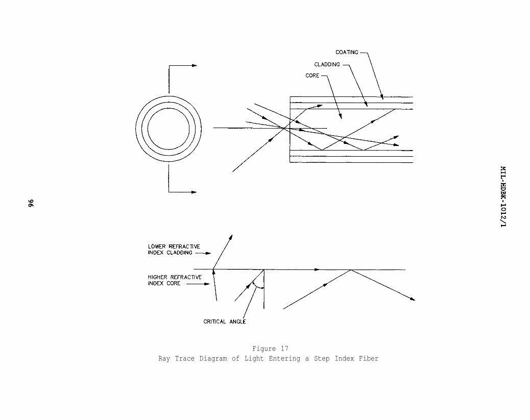
Figure 17Ray Trace Diagram of Light Entering a Step Index Fiber
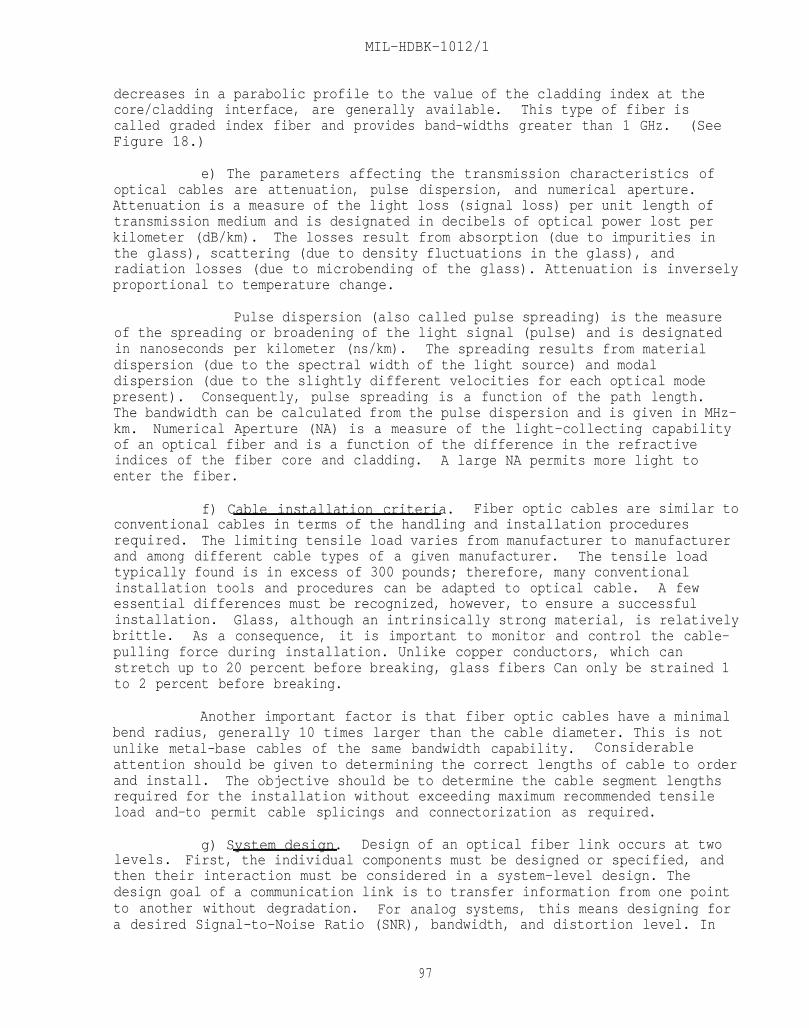
MIL-HDBK-1012/1
decreases in a parabolic profile to the value of the cladding index at thecore/cladding interface, are generally available. This type of fiber iscalled graded index fiber and provides band-widths greater than 1 GHz. (SeeFigure 18.)
e) The parameters affecting the transmission characteristics ofoptical cables are attenuation, pulse dispersion, and numerical aperture.Attenuation is a measure of the light loss (signal loss) per unit length oftransmission medium and is designated in decibels of optical power lost perkilometer (dB/km).the glass),
The losses result from absorption (due to impurities inscattering (due to density fluctuations in the glass), and
radiation losses (due to microbending of the glass). Attenuation is inverselyproportional to temperature change.
Pulse dispersion (also called pulse spreading) is the measureof the spreading or broadening of the light signal (pulse) and is designatedin nanoseconds per kilometer (ns/km). The spreading results from materialdispersion (due to the spectral width of the light source) and modaldispersion (due to the slightly different velocities for each optical modepresent). Consequently, pulse spreading is a function of the path length.The bandwidth can be calculated from the pulse dispersion and is given in MHz-km. Numerical Aperture (NA) is a measure of the light-collecting capabilityof an optical fiber and is a function of the difference in the refractiveindices of the fiber core and cladding. A large NA permits more light toenter the fiber.
f) Cable installation criteria. Fiber optic cables are similar toconventional cables in terms of the handling and installation proceduresrequired. The limiting tensile load varies from manufacturer to manufacturerand among different cable types of a given manufacturer. The tensile loadtypically found is in excess of 300 pounds; therefore, many conventionalinstallation tools and procedures can be adapted to optical cable. A fewessential differences must be recognized, however, to ensure a successfulinstallation.brittle.
Glass, although an intrinsically strong material, is relativelyAs a consequence, it is important to monitor and control the cable-
pulling force during installation. Unlike copper conductors, which canstretch up to 20 percent before breaking, glass fibers Can only be strained 1to 2 percent before breaking.
Another important factor is that fiber optic cables have a minimalbend radius, generally 10 times larger than the cable diameter. This is notunlike metal-base cables of the same bandwidth capability. Considerableattention should be given to determining the correct lengths of cable to orderand install. The objective should be to determine the cable segment lengthsrequired for the installation without exceeding maximum recommended tensileload and-to permit cable splicings and connectorization as required.
g) System design. Design of an optical fiber link occurs at twolevels. First, the individual components must be designed or specified, andthen their interaction must be considered in a system-level design. Thedesign goal of a communication link is to transfer information from one pointto another without degradation. For analog systems, this means designing fora desired Signal-to-Noise Ratio (SNR), bandwidth, and distortion level. In
97
MIL-HDBK-1012/1
Figure 18Graded Index Fiber
98
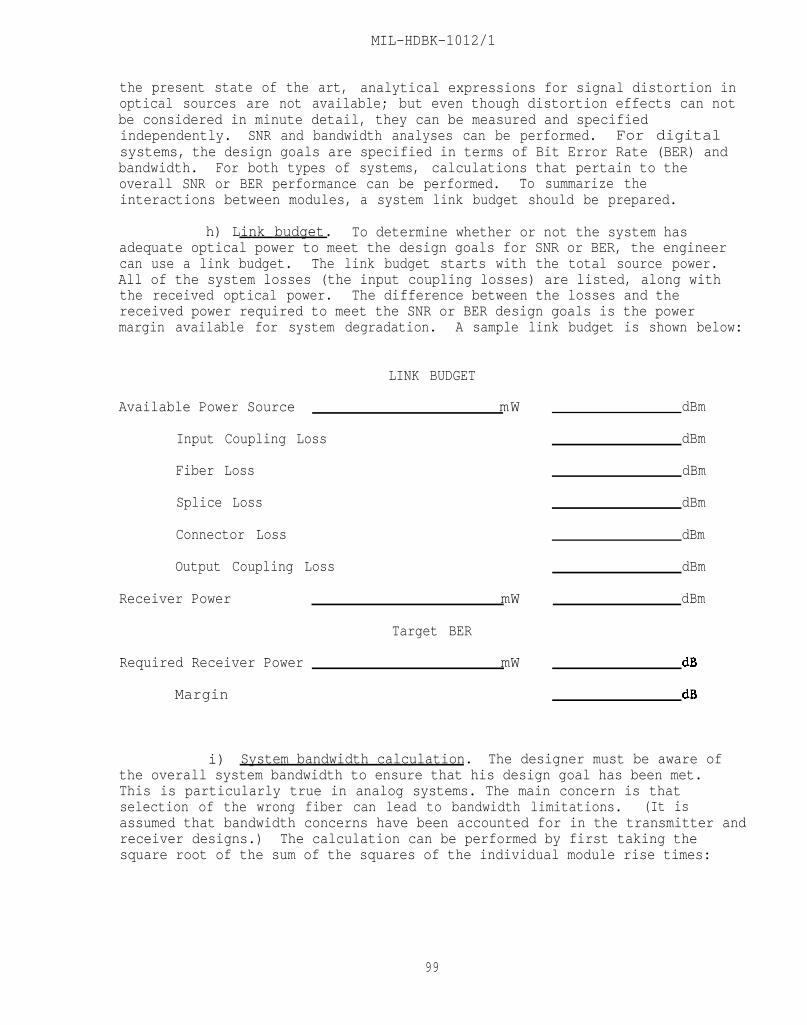
MIL-HDBK-1012/1
the present state of the art, analytical expressions for signal distortion inoptical sources are not available; but even though distortion effects can notbe considered in minute detail, they can be measured and specifiedindependently. SNR and bandwidth analyses can be performed. For digital systems, the design goals are specified in terms of Bit Error Rate (BER) andbandwidth. For both types of systems, calculations that pertain to theoverall SNR or BER performance can be performed. To summarize theinteractions between modules, a system link budget should be prepared.
h) Link budget. To determine whether or not the system hasadequate optical power to meet the design goals for SNR or BER, the engineercan use a link budget. The link budget starts with the total source power.All of the system losses (the input coupling losses) are listed, along withthe received optical power. The difference between the losses and thereceived power required to meet the SNR or BER design goals is the powermargin available for system degradation. A sample link budget is shown below:
Available Power Source
Input Coupling Loss
Fiber Loss
Splice Loss
Connector Loss
Output Coupling Loss
Receiver Power
Required Receiver Power
Margin
LINK BUDGET
mW
mW
Target BER
mW
dBm
dBm
dBm
dBm
dBm
dBm
dBm
i) System bandwidth calculation. The designer must be aware ofthe overall system bandwidth to ensure that his design goal has been met.This is particularly true in analog systems. The main concern is thatselection of the wrong fiber can lead to bandwidth limitations. (It isassumed that bandwidth concerns have been accounted for in the transmitter andreceiver designs.) The calculation can be performed by first taking thesquare root of the sum of the squares of the individual module rise times:
99
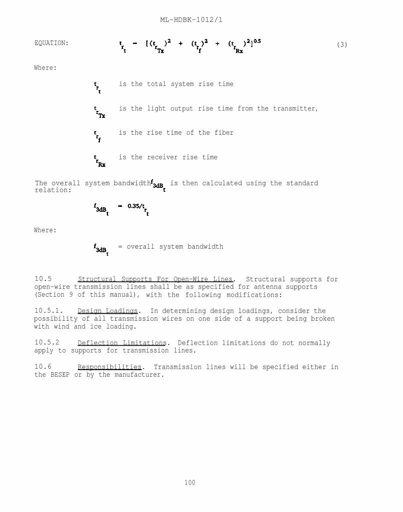
ML-HDBK-1012/1
EQUATION:
Where:
is the total system rise time
is the light output rise time from the transmitter,
is the rise time of the fiber
is the receiver rise time
The overall system bandwidth is then calculated using the standardrelation:
Where:
= overall system bandwidth
10.5 Structural Supports For Open-Wire Lines. Structural supports foropen-wire transmission lines shall be as specified for antenna supports(Section 9 of this manual), with the following modifications:
10.5.1. Design Loadings. In determining design loadings, consider thepossibility of all transmission wires on one side of a support being brokenwith wind and ice loading.
(3)
10.5.2 Deflection Limitations. Deflection limitations do not normallyapply to supports for transmission lines.
10.6 Responsibilities. Transmission lines will be specified either inthe BESEP or by the manufacturer.
100

MIL-HDBK-1012/1
BIBLIOGRAPHY
rican National Institute, Inc. (ANSI). 1430 Broadway. New York,NY 10018.
A156.2-1976 Locks and Lock Trim
C95.1-1982 Safety Levels with Respect co Human Exposure to RadioFrequency Electronic Fields, 300 KHz to 100 GHz.
C95.2-1982 Radio Frequency Radiation Hazard Warning Symbol.
Federal Specification, available from the Superintendent of Documents, U.S.Government Printing Officer, Washington, D.C. 20402.
AA-D-600B Door, Vault, Security
FF-H-106 Hardware, Builders', Locks and Door Trim, GeneralSpecification for
FF-H-116 Hinges, Hardware, Builders'
FF-H-121 Hardware, Builders', Door Closers
Industrial Laminated Thermosetting Products; NEMA Standard LI 1-1971 (R1976),National Electrical Manufacturers Association, 2101 "L" Street, N.W.,Washington, DC 20037.
Information Gate-keepers, Inc., Brookline, Massachusetts
Design Curves for Optical Waveguide Digital Communication Systems, Vol. 3.
Fiber Optics Design Aid Package, Vol. 4, Parts 1 and 2
Design Handbook for Optical Fiber Systems, Vol 2
Intrusion Detection System, NAVFAC DM 13.02, available from Naval Publicationsand Forms Center, 5801 Tabor Avenue, Philadelphia, PA 19120.
Life-Cycle Costing Manual for the Federal Energy Management Programs, NationalBureau of Standards Handbook 135, December 1980, available from theSuperintendent of Documents, U.S. Government Printing Office, Washington, DC20402.
Locks and Lock Trims, BHMA 601, Builders Hardware Manufacturers Association,Inc., c/o Trade Group Associates, Managers, 60 East 42nd Street, Room 511,New York, NY 10165.
Military Handbook. Standards and Specifications, available from NavalPublications and Forms Center, 5801, Tabor Avenue, Philadelphia, PA 19120.Private individuals and organizations may purchase from the Superintendent ofDocuments, U.S. Government Printing Office, Washington, D.C. 20420.
101
MIL-HDBK-1012/1
MIL-HDBK-1002/5 Timber Structures
MIL-HDBK-1002/6 Aluminum Structures, Composite Structures,Structural Plastics, and Fiber-ReinforcedComposites
MIL-L-15596 Lock, Combination (Safe and Safe Locker)
Multi-mode Optical Waveguides with Graded Refractive Index: Theory of PowerLaunching, P. DiVita and R. Vanucci, No. 11, 2765-2772, Applied Optics, 15(1976).
National Fire Codes, available from National Fire Protection Association,Batterymarch Park, Quincy, MA 02269
NFPA 255 Standard for Business Materials Test of SurfaceBurning, Characteristics of
Naval Shore Electronics Criteria, available from Naval Publications and FormsCenter, 5801 Tabor Avenue, Philadelphia, PA 19120.
0101,101 General
0101,112 Microwave and Troposcatter Communications Systems
0101,115 Digital Computer Systems, Vol. II of II
0101, Appendix VIII Handbook of Naval Shore Station ElectronicsCriteria
NAVFACENGCOM Guide Specification, NFGS-16650 Radio Frequency InterferencePower Line Filters, available from the Commanding Officer, Naval Publicationsand Forms Center, 5801 Tabor Avenue, Philadelphia, PA 19120.
Optical Communications: Devices, Circuits, and Systems, M. J. Howes andD. V. Morgan, from John Wiley & Sons, Inc., New York.
Receiver Designs for Fiber Optic Communications Optimization in Terms ofExcess Noise Factors that Depend on Avalanche Gains, Y. Takasaki andM. Maeda, COM-24(1976) No. 12, 13-1346, IEE Transactions on Communications,available from Institute of Electrical and Electronics Engineers, Inc., 345East 47th Street, New York, NY 10017.
Threshold Limit Values for Chemical Substances and Physical Agents in the WorkEnvironment with Intended Changes for 1982, American Conference ofGovernmental Industrial Hygienists.
Underwriters Laboratories. Inc., UL 768 Combination Locks, 333 Pfingston Road,Northbrook, IL 60062
Utilization of Optical-Frequency Carriers for Low and Moderate BandwidthChannels, W. M. Hubbard, Bell System Technical Journal, 52 (1973), No. 5,731-765.
102
MIL-HDBK-1012/1
REFERENCES
STANDARDS
MILITARY
MIL-STD-188/124
NOTE: Unless otherwise specified in the text,users of this handbook should utilize the latestrevisions of the documents cited herein.
FEDERAL/MILITARY SPECIFICATIONS, STANDARDS, BULLETINS, HANDBOOKS, AND NAVFACGUIDE SPECIFICATIONS:
The following specifications, standards, and handbooks form a part of thisdocument to the extent specified herein. Unless otherwise indicated, copiesare available from Commanding Officer, Naval Publications and Forms Center,ATTENTION: NPODS, 5801 Tabor Avenue, Philadelphia, PA 19120-5099.
SPECIFICATIONS
FEDERAL
W-L-305 Light Set, General Illumination(Emergency or Auxiliary)
RR-F-191 Fencing Wire (Chain-Link Fabric)
MILITARY
MIL-F-29046 Flooring, Raised; General Specification for
MIL-P-43607 Padlock, Key Operated, High Security,Shrouded Shackle
Grounding, Bonding, and Shielding for CommonLong Haul/Tactical Communication Systems
MIL-STD-210
MIL-STD-461
MIL-STD-882 System Safety Program Requirements
MIL-STD-1425 Safety Design Requirements for MilitaryLasers and Associated Support Equipment
MIL-STD-1472
Climatic Extremes for Military Equipment
Electromagnetic Emission and SusceptibilityRequirements for the Control ofElectromagnetic Interference
Human Engineering Design Criteria forMilitary Systems, Equipment and Facilities
103
MIL-HDBK-1012/1
HANDBOOKS
MIL-HDBK-411Volume I
Power and Environmental Control for thePhysical Plant of DOD Long HaulCommunications Power
MIL-HDBK-411Volume II
Power and Environmental Control for thePhysical Plant of DOD Long HaulCommunications Environmental Control
MIL-HDBK-419Volume I
Grounding, Bonding, and Shieldingfor Electronic Equipments and Facilities,Basic Theory
MIL-HDBK-419Volume II
Grounding, Bonding, and Shielding forElectronic Equipments and Facilities,Applications
MIL-HDBK-1001/2
MIL-HDBK-1002/3
MIL-HDBK-1005/8
MIL-HDBK-1008
Materials and Building Components
Steel Structures
Domestic Wastewater Control
Fire Protection for Facilities EngineeringDesign and Construction
MIL-HDBK-1012/2 High Altitude Electromagnetic PulseProtection
MIL-HDBK-1013/1 Design Guidelines for Physical Security ofFixed Land-Based Facilities
MIL-HDBK-1190 Facility Planning and Design Guide
NAVFAC GUIDE SPECIFICATIONS
NFGS-13093
NFGS-13094
NFGS 13947
NFGS 13948
NFGS 13949
NFGS 13950
Radio Frequency Shielded Enclosures,Demountable Type
Radio Frequency Shielded Enclosures, WeldedType
EMCS, Large System Configuration
EMCS, Medium System Configuration
EMCS, Small System Configuration
EMCS, Micro System Configuration
104
MIL-HDBK-1012/1
NAVY MANUALS, DRAWINGS, P-PUBLICATIONS, AND MAINTENANCE OPERATING MANUALS:
Available from Commanding Officer, Naval Publications and Forms Center (NPFC),5801 Tabor Avenue, Philadelphia, PA 19120-5099. To Or&r these documents:Government agencies must use the Military Standard Requisitioning and IssueProcedure (MILSTRIP); the private sector must write to NPFC, ATTENTION: CashSales, Code 1051, 5801 Tabor Avenue, Philadelphia, PA 19120-5099.
DM-1.01 Basic Architectural Requirements and DesignConsiderations
DM-1.03 Architectural Acoustics
DM-2 Series Structural Engineering
DM-3 Series Mechanical Engineering
DM-3.01 Plumbing Systems
DM-3.03 Heating, Ventilating, Air Conditioning andDehumidifying Systems
DM-4.05 400 Hz Generation and Distribution Systems
DM-4.07 Wire Communication and Signal Systems
DM-4.09 Energy Monitoring and Control Systems
DM-5.03 Drainage Systems
DM-5.5 General Provisions and Geometric Design forRoads, Streets, Walks, and Open Storage Areas
DM-5.12 Fencing, Gates, and Guard Towers
DM-7 Series Soils and Foundations
DM-7.02 Foundations and Earth Structures
P-89 Engineering Weather Data
P-442 Economic Analysis Handbook
NAVY DEPARTMENTAL INSTRUCTIONS: Available from Commanding Officer, NavalPublications and Forms Center, ATTENTION: Code 3015, 5801 Tabor Avenue,Philadelphia, PA 19120-5099.
NAVELEXINST 5100.12 Navy Laser Hazards Prevention Program
NAVELEXINST 11000.1 The Base Electronic System Engineering Plan(BESEP and Procedure for Utilization of, 21July 71)
105

MIL-HDBK-1012/1
NAVMED P-5055
NAVMEDCOMINST 6470.2
NAVSEA OP3565/NAVAIR 16-1-529/NAVELEX 0967-LPO624-6010 VOL. I
OPNAVINST 4620.8B
OPNAVINST 5100.23B
OPNAVNOTE 5100SER 45/5u39486730 JULY 1985
NAVELEK 0101 Series
NAVELEX 0101,102
NAVELEX 0101,103
NAVELEX 0101,104
NAVELEX 0101,105
NAVELEX 0101,106
NAVELEX 0101,107
NAVELEX 0101,108
NAVELEX 0101,109
NAVELEX 0101,110
NAVELEX 0101,111
NAVELEX 0101,113
NAVELEX 0101,114
Radiation Health Protection Manual
Laser Radiation Health Hazards
Technical Manual Electromagnetic RadiationHazards (U)
Use of Intermodal Containers, Special PurposeVans and Tactical Shelters
Navy Occupational Safety and Health ProgramManual
Personnel Protection Policy for Exposure toRadio-Frequency Radiation (RFR)
Naval Shore Electronics Criteria Manual
Naval Communications Station Design
HF Radio Propagation and Facility SiteSelection
HF Radio Antenna Systems
Satellite Communication Systems
Electromagnetic Compatibility andElectromagnetic Radiation Hazards
Naval Aeronautical Facilities
Naval Security Group Elements, Design andPerformance
Naval Training Facilities
Installation Standards and Practices
Digital Computer Systems, Vol. I of II
Navy VLF, LF, and MF Communications System
NAVELEX Calibration Program
OTHER GOVERNMENT DOCUMENTS AND PUBLICATIONS:
The following Government documents and publications form a part of thisdocument to the extent specified herein.
106

MIL-HDBK-1012/1
DEFENSE INTELLIGENCE AGENCY
DIAM-50-3-80 Physical Security Standards for SensitiveCompartmented Information Facilities
(Unless otherwise indicated, copies are available from Commander, NavyIntelligence Command, NIC-31, 4600 Silver Hill Road, Washington, D.C. 20389).
DEPARTMENT OF DEFENSE (DOD)
DOD 4630.7-M Major Fixed Command, Control andCommunications Facilities Power Systems DesignFeatures Manual
(Unless otherwise indicated copies are available from Superintendent ofDocuments, U.S. Government Printing Office, Washington, DC 20402).
FEDERAL AVIATION ADMINISTRATION (FAA)
Advisory Circular Obstruction Marking and LightingAC 70/7460-1F
(Unless otherwise indicated copies are available from U.S. Federal AviationAdministration, Office of Airport Standards (AAS-200) Department ofTransportation, 800 Independence Avenue, S.W., Washington, DC 20591).
NATIONAL SECURITY AGENCY (NSA)
NACSIM 5203 Guidelines for Facility Design and Red/BlackInstallations
(Unless otherwise indicated copies are available from National SecurityAgency, Director, US Navy Communication Security National Systems (CMSC), 3801Nebraska Avenue, N.W., Washington, DC 20390).
OCCUPATIONAL SAFETY AND HEALTH ADMINISTRATION (OSHA)
1910.23 Standards for General Industry
1926.403 Battery Rooms and Battery Charging
(Unless otherwise indicated copies are available from Superintendant ofDocuments, U.S. Government Printing Office, Washington, D.C. 20402).
107

HIL-HDBK-1012/1
NON-GOVERNMENT PUBLICATIONS:
The following publications form a part of this document to the extentspecified herein. Unless otherwise specified, the issues of the documentswhich are DOD adopted are those listed in the Department of Defense Index ofSpecification & Standards (DODISS).
American Hot Dip Galvanizers Association
The Design of Products to be Hot Dip Galvanized After Fabrication
(Unless otherwise indicated copies are available from American Hot DipGalvanizers Association, 1101 Connecticut Ave., N.W., Washington; DC 20036).
AMERICAN SOCIETY OF HEATING, REFRIGERATING AND AIR CONDITIONINGENGINEERS (ASHRAE)
Test Standard 52-76, Method of Testing Air-Cleaning DevicesUsed in General Ventilation for RemovingParticulate Matter
ASHRAE Handbook Series
1988 Handbook Equipment
1987 Handbook HVAC Systems and Applications
1986 Handbook Refrigeration Systems and Applications
1985 Handbook Fundamentals
(Unless otherwise indicated copies are available from, American Society ofHeating, Refrigerating and Air Conditioning Engineers, Inc. (ASHRAE), 1791Tullie Circle, N.E., Atlanta, GA 30329).
ELECTRONICS INDUSTRIES ASSOCIATION (EIA)
EIA Standard RS-222C Structural Standards for Steel AntennaTowers and Antenna Supporting Structures
(Unless otherwise indicated copies areavailable from the ElectronicsIndustries Association, 2001 Eye Street, N.W., Washington, DC 20006).
INTERNATIONAL ORGANIZATION FOR STANDARDIZATION (ISO)
Standard 669-1976 Freight Containers, External Dimensions,and Ratings
(Unless otherwise indicated copies are available from the InternationalOrganization for Standardization (ISO), 1 Rue De Varembe, Case Postale 56, CH1211, Geneva 20, Switzerland).
108

MIL-HDBK-1012/1
ILLUMINATING ENGINEERS SOCIETY (IES)
Lighting Handbook
(Unless otherwise indicated copies are available from the IlluminatingEngineers Society (IES), 345 East 47th Street, New York, NY 10017).
NATIONAL FIRE PROTECTION ASSOCIATION
NFPA 70 National Electrical Code
NFPA 72A Standard for the Installation, Maintenance,and Use of Local Protective Signaling Systemsfor Guard's Tour, Fire Alarm, and SupervisoryService
NFPA 72E Standard on Automatic Fire Detectors
NFPA 75 Standard for the Protection of Computer/DataProcessing Equipment
NFPA 78 Lightning Protection Code
NFPA 90A Standard for the Installation of AirConditioning and Ventilation Systems
NFPA 101 Code for Safety to Life from Fire in Buildingsand Structures
(Unless otherwise indicated copies are available from National Fire ProtectionAssociation, Batterymarch Park, Quincy, MA 02269).
UNDERWRITERS LABORATORIES, INC. (UL)
UL 723-83 Test for Surface Burning Characteristics ofBuilding Materials
(Unless otherwise indicated copies are available from UnderwritersLaboratories, Inc., 333 Pfingston Road, Northbrook, IL 60062).
CUSTODIANNAVY - YD
PREPARING ACTIVITYNAVY - YD
PROJECT NO.FACR-0363
109

INSTRUCTIONS: In a continuing effort to make our standardization documents better, the DOD provides this form for use insubmitting comments and suggestions for improvements. All users of military standardization documents are invited to providesuggestions. This form may be detached, folded along the lines indicated, taped along the loose edge (DO NOT STAPLE), andmailed. In block 5, be as specific as possible about particular problem areas such as working which required interpretation, was too rigid, restrictive, loose, ambiguous, or was incompatible, and give proposed wording changes which would alleviate theproblems. Enter in block 6 any remarks not related to a specific paragraph of the document. If block 7 is filled out, anacknowledgement will be mailed to you within 30 days to let you know that your comments were received and are beingconsidered.
NOTE: This form may not be used to request copies of documents, nor to request waivers, deviations, or clarification ofspecification requirements on current contracts. Comments submitted on this form do not constitute or imply authorizationto waive any portion of the referenced document(s) or amend contractual requirements.
(Fold along this line)
(Fold along this line)
DEPARTMENT OF THE NAVY
IIIIIIUNITED STATES
OFFICIAL BUSINESSP E N A L T Y F O R P R I V A T E U S E $ 3 0 0 BUSINESS REPLY MAIL
FIRST CLASS PERMIT NO. 12503 W A S H l N G T O N D . C .
POSTAGE WlLL BE PAlD BY THE DEPARTMENT OF THE NAVY
COMMANDING OFFICERCHESAPEAKE DIVISIONNAVAL FACILITIES ENGINEERING COMMANDCODE 406CWASHINGTON, DC 20374-2121