Embed Size (px)
Citation preview
86www.conesys.com [email protected]
MIL–D
TL–
83723 S III
MIL-DTL-83723 Series IIIFeatures and ApplicationBayonet and Threaded Coupling
– –www.conesys.com [email protected]
Features and Application
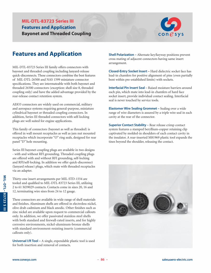
MIL-DTL-83723 Series III family offers connectors with bayonet and threaded coupling including lanyard-releasequick-disconnects. These connectors combine the best featuresof MIL-DTL-26500 and NAS 1599 miniature connectorspecifications. They are intermateable with both bayonet andthreaded 26500 connectors (exception: shell size 8, threadedcoupling only) and have the added advantage provided by therear-release contact retention system.
AE833 connectors are widely used on commercial, militaryand aerospace systems requiring general-purpose, miniaturecylindrical bayonet or threaded coupling connectors. In addition, Series III threaded connectors with self-lockingplugs are well suited for engine applications.
This family of connectors (bayonet as well as threaded) isoffered in wall mount receptacles as well as jam nut mountedreceptacles which incorporate “O” ring seals, designed for rearpanel “D” hole mounting.
Series III bayonet-coupling plugs are available in two designs- with and without RFI grounding. Threaded coupling plugsare offered with and without RFI grounding, self-locking and RFI/self-locking. In addition we offer quick-disconnect (lanyard release) plugs, which mate with threaded receptaclesvia an adapter.
Thirty-one insert arrangements per MIL-STD-1554 aretooled and qualified to MIL-DTL-83723 Series III, utilizing 2 to 61 M39029 contacts. Contacts come in sizes 20, 16 and12, terminating wire sizes from 24 to 12 gauge.
These connectors are available in wide range of shell materialsand finishes. Aluminum shells are offered in electroless nickel,olive drab cadmium and black anodic. Other finishes such aszinc nickel are available upon request to commercial calloutsonly. In addition, we offer passivated stainless steel shellswith both standard and firewall-rated inserts, and for highlycorrosive environments, nickel-aluminum-bronze shellswith standard environment-resisting inserts (commercialcallouts only).
Universal I/R Tool – A single, expendable plastic tool is usedfor both insertion and removal of contacts.
Shell Polarization – Alternate key/keyway positions preventcross mating of adjacent connectors having same insertarrangement.
Closed-Entry Socket Insert – Hard dielectric socket face haslead-in chamfers for positive alignment of pins (even partiallybent within pre-established limits) with sockets.
Interfacial Pin Insert Seal – Raised moisture barriers aroundeach pin, which mate into lead-in chamfers of hard facesocket insert, provide individual contact sealing. Interfacialseal is never touched by service tools.
Elastomer Wire Sealing Grommet – Sealing over a widerange of wire diameters is assured by a triple wire seal in eachcavity at the rear of the connector.
Superior Contact Stability – Rear release crimp contact system features a stamped beryllium-copper retaining clipcaptivated by molded-in shoulders of each contact cavity inthe insulator. A rear-inserted M81969 plastic tool expands thetines beyond the shoulder, releasing the contact.
87www.conesys.com [email protected]
MIL–D
TL–
83723 S III
MIL-DTL-83723 Series IIIPerformance Specifications
Bayonet and Threaded Coupling
– –
Performance Specifications
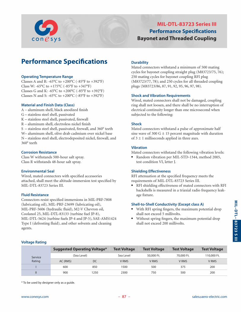
Operating Temperature RangeClasses A and R: -65°C to +200°C (-85°F to +392°F)Class W: -65°C to +175°C (-85°F to +347°F)Classes G and K: -65°C to +200°C (-85°F to +392°F)Classes N and S: -65°C to +200°C (-85°F to +392°F)
Material and Finish Data (Class)A – aluminum shell, black anodized finishG – stainless steel shell, passivatedK – stainless steel shell, passivated, firewallR – aluminum shell, electroless nickel finishS – stainless steel shell, passivated, firewall, and 360° teethW– aluminum shell, olive drab cadmium over nickel baseN– stainless steel shell, electrodeposited nickel, firewall, and360° teeth
Corrosion ResistanceClass W withstands 500-hour salt spray.Class R withstands 48-hour salt spray.
Environmental SealWired, mated connectors with specified accessoriesattached, shall meet the altitude-immersion test specified by MIL-DTL-83723 Series III.
Fluid ResistanceConnectors resist specified immersions in MIL-PRF-7808(lubricating oil), MIL-PRF-23699 (lubricating oil), MIL-PRF-5606 (hydraulic fluid), M2-V Chevron oil,Coolanol 25, MIL-DTL-83133 (turbine fuel JP-8), MIL-DTL-5624 (turbine fuels JP-4 and JP-5), SAE-AMS1424Type I (defrosting fluid), and other solvents and cleaningagents.
Voltage Rating
DurabilityMated connectors withstand a minimum of 500 matingcycles for bayonet coupling straight plug (M83723/75, 76);250 mating cycles for bayonet coupling RFI plug(M83723/77, 78); and 250 cycles for all threaded couplingplugs (M83723/86, 87, 91, 92, 95, 96, 97, 98).
Shock and Vibration RequirementsWired, mated connectors shall not be damaged, couplingring shall not loosen, and there shall be no interruption ofelectrical continuity longer than one microsecond whensubjected to the following:
ShockMated connectors withstand a pulse of approximate halfsine wave of 300 G ± 15 percent magnitude with durationof 3 ± 1 milliseconds applied in three axes.
VibrationMated connectors withstand the following vibration levels:� Random vibration per MIL-STD-1344, method 2005,test condition VI, letter J.
Shielding EffectivenessRFI attenuation at the specified frequency meets therequirements of MIL-DTL-83723 Series III.� RFI shielding effectiveness of mated connectors with RFIbackshells is measured in a triaxial radio frequency leak-age fixture.
Shell-to-Shell Conductivity (Except class A)� With RFI spring fingers, the maximum potential dropshall not exceed 5 millivolts.
� Without spring fingers, the maximum potential dropshall not exceed 200 millivolts.
* To be used by designer only as a guide.
ServiceRating
Suggested Operating Voltage* Test Voltage Test Voltage Test Voltage Test Voltage
(Sea Level) Sea Level 50,000 Ft. 70,000 Ft. 110,000 Ft.
AC (RMS) DC V RMS V RMS V RMS V RMS
I 600 850 1500 500 375 200
II 900 1250 2300 750 500 200
88www.conesys.com [email protected]
MIL–D
TL–
83723 S III
MIL-DTL-83723 Series IIIPart Number DevelopmentBayonet Coupling
Military and Aero-Electric Part Number Development
– –
Note 1: Each connector is furnished with contacts unlessordered less contacts (L/C) as follows: One spare contact forinserts requiring 2 to 26 of each contact and two spares forinserts with 27 or more of each size, and a minimum of onesealing plug up to 15% of the number of contacts of eachsize. In addition, one insertion/removal tool of each size isincluded.
Note 2: Proper part number marking has no “0” in front ofsingle digit shell size (8), but it does include the “0” in frontof single digit layout. Examples: M83723/72W803N andM83723/77G10056. Please note that in this series “N” fornormal is included in part number marking.
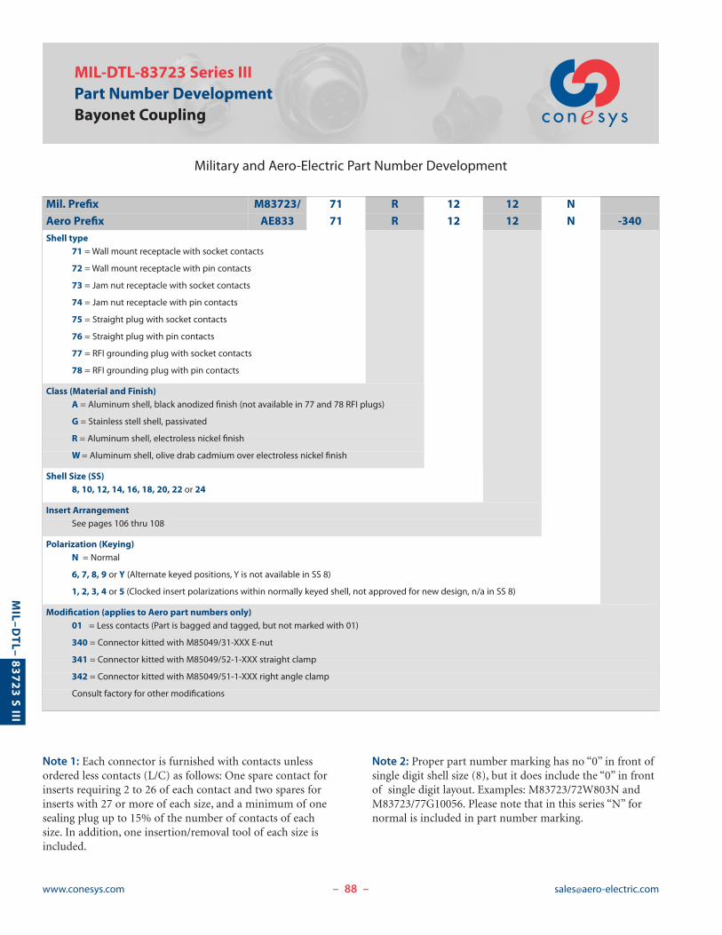
Mil. Prefix M83723/ 71 R 12 12 N
Aero Prefix AE833 71 R 12 12 N -340Shell type
71 = Wall mount receptacle with socket contacts
72 = Wall mount receptacle with pin contacts
73 = Jam nut receptacle with socket contacts
74 = Jam nut receptacle with pin contacts
75 = Straight plug with socket contacts
76 = Straight plug with pin contacts
77 = RFI grounding plug with socket contacts
78 = RFI grounding plug with pin contacts
Class (Material and Finish)A = Aluminum shell, black anodized finish (not available in 77 and 78 RFI plugs)
G = Stainless stell shell, passivated
R = Aluminum shell, electroless nickel finish
W= Aluminum shell, olive drab cadmium over electroless nickel finish
Shell Size (SS)8, 10, 12, 14, 16, 18, 20, 22 or 24
Insert ArrangementSee pages 106 thru 108
Polarization (Keying)N = Normal
6, 7, 8, 9 or Y (Alternate keyed positions, Y is not available in SS 8)
1, 2, 3, 4 or 5 (Clocked insert polarizations within normally keyed shell, not approved for new design, n/a in SS 8)
Modification (applies to Aero part numbers only)01 = Less contacts (Part is bagged and tagged, but not marked with 01)
340 = Connector kitted with M85049/31-XXX E-nut
341 = Connector kitted with M85049/52-1-XXX straight clamp
342 = Connector kitted with M85049/51-1-XXX right angle clamp
Consult factory for other modifications
89www.conesys.com [email protected]
MIL–D
TL–
83723 S III
M83723/71, 72Wall Mounting Receptacle
AE83371, 72
Bayonet Coupling, Crimp Removable, Rear Release
– –
MASTERKEYWAY
4x MINOR KEYS
[ D
3x BAYONET PINSEQUALLY SPACED
4x [ CMOUNTINGHOLES
3 ACCESSORY TEETHEQUALLY SPACED
E ACCESSORY THREAD
[ FMAX
GROMMET
.290(7.37) MIN FULL THREAD
A
B
1.300(33.02)MAX
.728(18.49)
.708(17.98)
.190(4.83)
.130(3.30)GROMMETEXTENSION
.072(1.83)
.052(1.32)
BLUE COLOR BANDS
Page 88 Completed Part NumberPage 104 Contacts, Sealing Plugs and ToolsPages 107, 108 Insert ArrangementsPage 87 Performance SpecificationsPage 106 Insert Availability and Contact InformationPage 102 Polarization
ShellSize
A B � C � D E � F
+.000 +.00 Accessory Thread±.005 ±.13 (TP) ±.005 ±.13 -.005 -.13 Class 2A Maximum
inch mm inch mm inch mm inch mm inch mm
8 .812 20.62 .594 15.09 .120 3.05 .536 13.61 1/2-20UNF .305 7.75
10 .937 23.80 .719 18.26 .120 3.05 .659 16.74 5/8-24UNEF .405 10.29
12 1.031 26.19 .812 20.62 .120 3.05 .829 21.06 3/4-20UNEF .531 13.49
14 1.125 28.58 .906 23.01 .120 3.05 .898 22.81 7/8-20UNEF .665 16.89
16 1.250 31.75 .969 24.61 .120 3.05 1.025 26.04 1-20UNEF .790 20.07
18 1.343 34.11 1.062 26.97 .120 3.05 1.131 28.73 1-1/16-18UNEF .869 22.07
20 1.437 36.50 1.156 29.36 .120 3.05 1.256 31.90 1-3/16-18UNEF .994 25.25
22 1.562 39.67 1.250 31.75 .120 3.05 1.381 35.08 1-5/16-18UNEF 1.119 28.42
24 1.703 43.26 1.375 34.93 .149 3.78 1.506 38.25 1-7/16-18UNEF 1.244 31.60
90www.conesys.com [email protected]
MIL–D
TL–
83723 S III
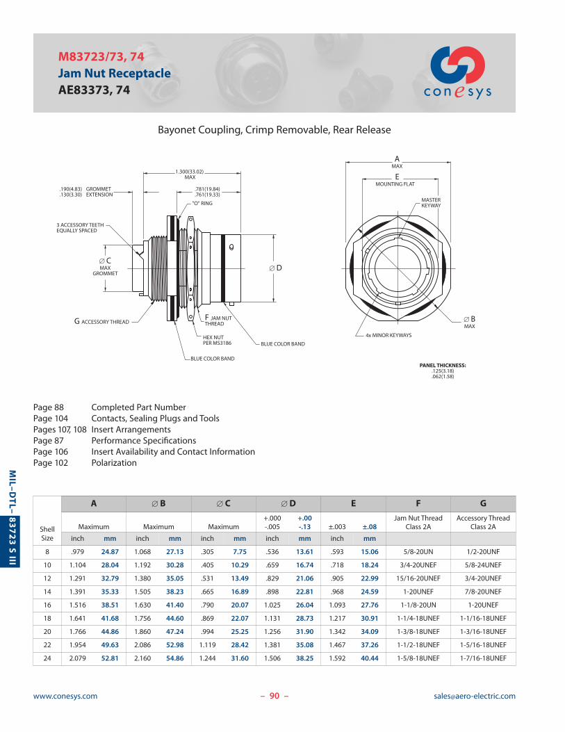
M83723/73, 74Jam Nut ReceptacleAE83373, 74
Bayonet Coupling, Crimp Removable, Rear Release
– –
BLUE COLOR BAND
BLUE COLOR BAND
.781(19.84)
.761(19.33).190(4.83).130(3.30)
GROMMETEXTENSION
HEX NUTPER MS3186
3 ACCESSORY TEETHEQUALLY SPACED
1.300(33.02) MAX
4x MINOR KEYWAYS
MASTERKEYWAY "O" RING
[ D
EMOUNTING FLAT
G ACCESSORY THREADF JAM NUT THREAD
[ CMAX
GROMMET
[ BMAX
AMAX
PANEL THICKNESS:.125(3.18).062(1.58)
Page 88 Completed Part NumberPage 104 Contacts, Sealing Plugs and ToolsPages 107, 108 Insert ArrangementsPage 87 Performance SpecificationsPage 106 Insert Availability and Contact InformationPage 102 Polarization
ShellSize
A � B � C � D E F G
+.000 +.00 Jam Nut Thread Accessory ThreadMaximum Maximum Maximum -.005 -.13 ±.003 ±.08 Class 2A Class 2A
inch mm inch mm inch mm inch mm inch mm
8 .979 24.87 1.068 27.13 .305 7.75 .536 13.61 .593 15.06 5/8-20UN 1/2-20UNF
10 1.104 28.04 1.192 30.28 .405 10.29 .659 16.74 .718 18.24 3/4-20UNEF 5/8-24UNEF
12 1.291 32.79 1.380 35.05 .531 13.49 .829 21.06 .905 22.99 15/16-20UNEF 3/4-20UNEF
14 1.391 35.33 1.505 38.23 .665 16.89 .898 22.81 .968 24.59 1-20UNEF 7/8-20UNEF
16 1.516 38.51 1.630 41.40 .790 20.07 1.025 26.04 1.093 27.76 1-1/8-20UN 1-20UNEF
18 1.641 41.68 1.756 44.60 .869 22.07 1.131 28.73 1.217 30.91 1-1/4-18UNEF 1-1/16-18UNEF
20 1.766 44.86 1.860 47.24 .994 25.25 1.256 31.90 1.342 34.09 1-3/8-18UNEF 1-3/16-18UNEF
22 1.954 49.63 2.086 52.98 1.119 28.42 1.381 35.08 1.467 37.26 1-1/2-18UNEF 1-5/16-18UNEF
24 2.079 52.81 2.160 54.86 1.244 31.60 1.506 38.25 1.592 40.44 1-5/8-18UNEF 1-7/16-18UNEF
91www.conesys.com [email protected]
MIL–D
TL–
83723 S III
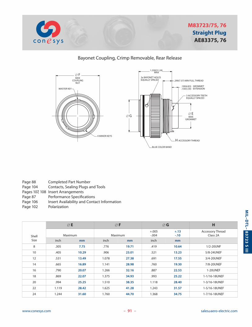
M83723/75, 76Straight PlugAE83375, 76
Bayonet Coupling, Crimp Removable, Rear Release
– –
BLUE COLOR BAND
MASTER KEY
4 MINOR KEYS
3x BAYONET HOLESEQUALLY SPACED
3 ACCESSORY TEETHEQUALLY SPACED
H ACCESSORY THREAD
[ EMAX
GROMMET
.290(7.37) MIN FULL THREAD
.190(4.83)
.130(3.30)GROMMETEXTENSION
[ FMAX
COUPLINGNUT
[ G
1.230(31.24)MAX
Page 88 Completed Part NumberPage 104 Contacts, Sealing Plugs and ToolsPages 107, 108 Insert ArrangementsPage 87 Performance SpecificationsPage 106 Insert Availability and Contact InformationPage 102 Polarization
ShellSize
� E � F � G H
+.005 +.13 Accessory ThreadMaximum Maximum -.004 -.10 Class 2A
inch mm inch mm inch mm
8 .305 7.75 .776 19.71 .419 10.64 1/2-20UNF
10 .405 10.29 .906 23.01 .521 13.23 5/8-24UNEF
12 .531 13.49 1.078 27.38 .691 17.55 3/4-20UNEF
14 .665 16.89 1.141 28.98 .760 19.30 7/8-20UNEF
16 .790 20.07 1.266 32.16 .887 22.53 1-20UNEF
18 .869 22.07 1.375 34.93 .993 25.22 1-1/16-18UNEF
20 .994 25.25 1.510 38.35 1.118 28.40 1-3/16-18UNEF
22 1.119 28.42 1.625 41.28 1.243 31.57 1-5/16-18UNEF
24 1.244 31.60 1.760 44.70 1.368 34.75 1-7/16-18UNEF
92www.conesys.com [email protected]
MIL–D
TL–
83723 S III
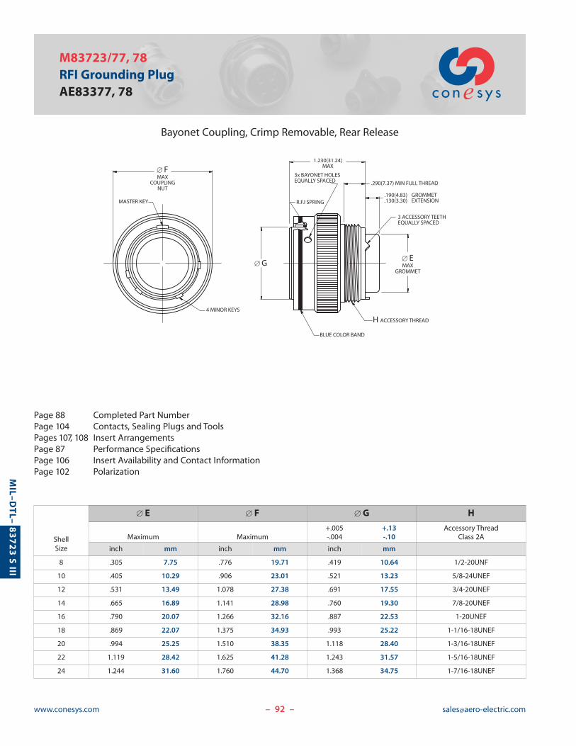
M83723/77, 78RFI Grounding PlugAE83377, 78
Bayonet Coupling, Crimp Removable, Rear Release
– –
Page 88 Completed Part NumberPage 104 Contacts, Sealing Plugs and ToolsPages 107, 108 Insert ArrangementsPage 87 Performance SpecificationsPage 106 Insert Availability and Contact InformationPage 102 Polarization
ShellSize
� E � F � G H
+.005 +.13 Accessory ThreadMaximum Maximum -.004 -.10 Class 2A
inch mm inch mm inch mm
8 .305 7.75 .776 19.71 .419 10.64 1/2-20UNF
10 .405 10.29 .906 23.01 .521 13.23 5/8-24UNEF
12 .531 13.49 1.078 27.38 .691 17.55 3/4-20UNEF
14 .665 16.89 1.141 28.98 .760 19.30 7/8-20UNEF
16 .790 20.07 1.266 32.16 .887 22.53 1-20UNEF
18 .869 22.07 1.375 34.93 .993 25.22 1-1/16-18UNEF
20 .994 25.25 1.510 38.35 1.118 28.40 1-3/16-18UNEF
22 1.119 28.42 1.625 41.28 1.243 31.57 1-5/16-18UNEF
24 1.244 31.60 1.760 44.70 1.368 34.75 1-7/16-18UNEF
3x BAYONET HOLESEQUALLY SPACED .290(7.37) MIN FULL THREAD
.190(4.83)
.130(3.30)GROMMETEXTENSION
BLUE COLOR BAND
R.F.I SPRING
3 ACCESSORY TEETHEQUALLY SPACED
H ACCESSORY THREAD
[ EMAX
GROMMET[ G
1.230(31.24)MAX
MASTER KEY
4 MINOR KEYS
[ FMAX
COUPLINGNUT
93www.conesys.com [email protected]
MIL–D
TL–
83723 S III
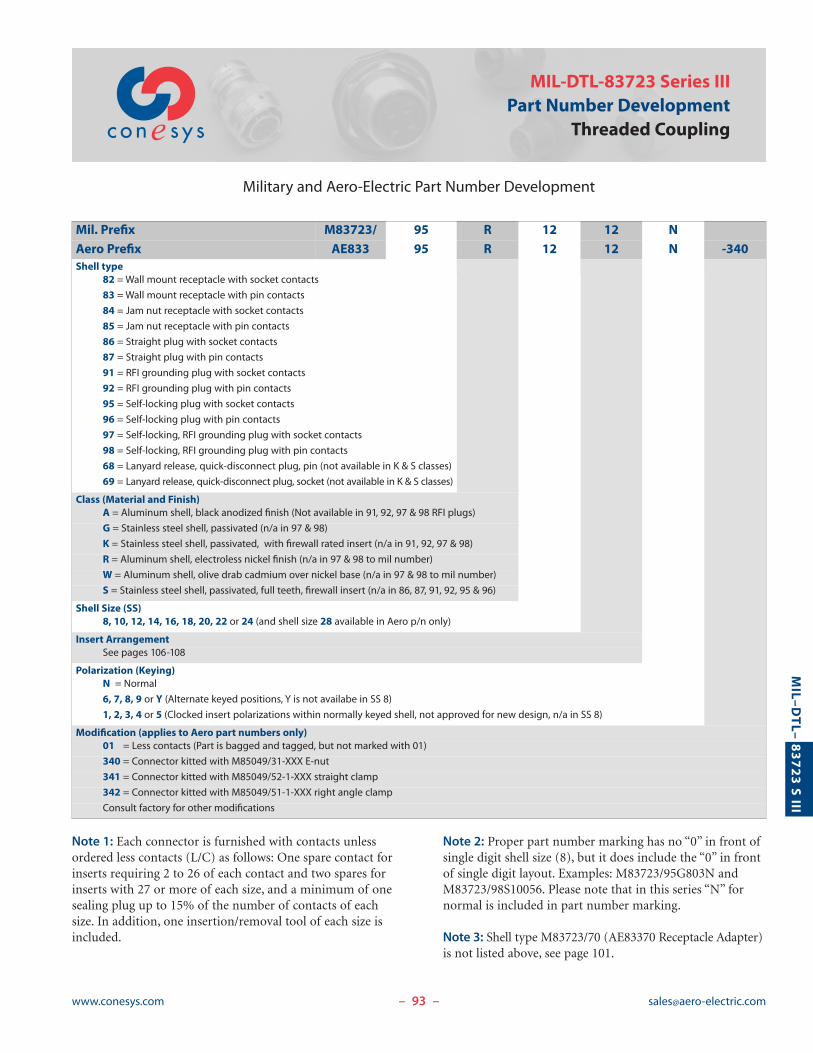
MIL-DTL-83723 Series IIIPart Number Development
Threaded Coupling
Military and Aero-Electric Part Number Development
– –
Note 1: Each connector is furnished with contacts unlessordered less contacts (L/C) as follows: One spare contact forinserts requiring 2 to 26 of each contact and two spares forinserts with 27 or more of each size, and a minimum of onesealing plug up to 15% of the number of contacts of eachsize. In addition, one insertion/removal tool of each size isincluded.
Note 2: Proper part number marking has no “0” in front ofsingle digit shell size (8), but it does include the “0” in frontof single digit layout. Examples: M83723/95G803N andM83723/98S10056. Please note that in this series “N” fornormal is included in part number marking.
Note 3: Shell type M83723/70 (AE83370 Receptacle Adapter)is not listed above, see page 101.
Mil. Prefix M83723/ 95 R 12 12 N
Aero Prefix AE833 95 R 12 12 N -340Shell type
82 = Wall mount receptacle with socket contacts
83 = Wall mount receptacle with pin contacts
84 = Jam nut receptacle with socket contacts
85 = Jam nut receptacle with pin contacts
86 = Straight plug with socket contacts
87 = Straight plug with pin contacts
91 = RFI grounding plug with socket contacts
92 = RFI grounding plug with pin contacts
95 = Self-locking plug with socket contacts
96 = Self-locking plug with pin contacts
97 = Self-locking, RFI grounding plug with socket contacts
98 = Self-locking, RFI grounding plug with pin contacts
68 = Lanyard release, quick-disconnect plug, pin (not available in K & S classes)
69 = Lanyard release, quick-disconnect plug, socket (not available in K & S classes)
Class (Material and Finish)A = Aluminum shell, black anodized finish (Not available in 91, 92, 97 & 98 RFI plugs)
G = Stainless steel shell, passivated (n/a in 97 & 98)
K = Stainless steel shell, passivated, with firewall rated insert (n/a in 91, 92, 97 & 98)
R = Aluminum shell, electroless nickel finish (n/a in 97 & 98 to mil number)
W = Aluminum shell, olive drab cadmium over nickel base (n/a in 97 & 98 to mil number)
S = Stainless steel shell, passivated, full teeth, firewall insert (n/a in 86, 87, 91, 92, 95 & 96)
Shell Size (SS)8, 10, 12, 14, 16, 18, 20, 22 or 24 (and shell size 28 available in Aero p/n only)
Insert ArrangementSee pages 106-108
Polarization (Keying)N = Normal
6, 7, 8, 9 or Y (Alternate keyed positions, Y is not availabe in SS 8)
1, 2, 3, 4 or 5 (Clocked insert polarizations within normally keyed shell, not approved for new design, n/a in SS 8)
Modification (applies to Aero part numbers only)01 = Less contacts (Part is bagged and tagged, but not marked with 01)
340 = Connector kitted with M85049/31-XXX E-nut
341 = Connector kitted with M85049/52-1-XXX straight clamp
342 = Connector kitted with M85049/51-1-XXX right angle clamp
Consult factory for other modifications
H No. OF TEETHCLASSES: “N” & “S” ONLY
E ACCESSORY THREAD
.290(7.37) MIN FULL THREAD
.160(4.06) GROMMET
.010(0.25) EXTENSION
1.340(34.04) MAXCLASSES: “N” & “S” ONLY
E4 MINOR KEYWAYS
1.248(31.70)MAX
4x [ CMOUNTING HOLES
B
A
D MATING THREAD
.728(18.49)
.708(17.98)
FULL MATE INDICATOR COLOR: RED
[ FMAX
GROMMET[ FMAX
GROMMET
.290(7.37) MINFULL THREAD
.072(1.83)
.052(1.32)
.190(4.83) GROMMET
.130(3.30) EXTENSION
ACCESSORY THREAD
MASTERKEYWAY
BLUE COLOR BANDS
3 ACCESORY TEETHEQUALLY SPACED
PANEL THICKNESS: .125(3.18) MAX
94www.conesys.com [email protected]
MIL–D
TL–
83723 S III
M83723/82, 83Wall Mounting ReceptacleAE83382, 83
Threaded Coupling, Crimp Removable, Rear Release
– –
Page 93 Completed Part NumberPage 104 Contacts, Sealing Plugs and ToolsPages 107, 108 Insert ArrangementsPage 87 Performance SpecificationsPage 106 Insert Availability and Contact InformationPage 102 Polarization
ShellSize
A B � C D E � F H
+.005 +.13 Mating Thread Accessory Thread No. of±.005 ±.13 (TP) -.004 -.10 Class 2A Class 2A Maximum Teeth
inch mm inch mm inch mm inch mm
8 .812 20.62 .594 15.09 .120 3.05 9/16-24UNEF 1/2-20UNF .305 7.75 12
10 .937 23.80 .719 18.26 .120 3.05 11/16-24UNEF 5/8-24UNEF .405 10.29 15
12 1.031 26.19 .812 20.62 .120 3.05 7/8-20UNEF 3/4-20UNEF .531 13.49 21
14 1.125 28.58 .906 23.01 .120 3.05 15/16-20UNEF 7/8-20UNEF .665 16.89 24
16 1.250 31.75 .969 24.61 .120 3.05 1-1/16-18UNEF 1-20UNEF .790 20.07 30
18 1.343 34.11 1.062 26.97 .120 3.05 1-3/16-18UNEF 1-1/16-18UNEF .869 22.07 33
20 1.437 36.50 1.156 29.36 .120 3.05 1-5/16-18UNEF 1-3/16-18UNEF .994 25.25 36
22 1.562 39.67 1.250 31.75 .120 3.05 1-7/16-18UNEF 1-5/16-18UNEF 1.119 28.42 39
24 1.703 43.26 1.375 34.93 .149 3.78 1-9/16-18UNEF 1-7/16-18UNEF 1.244 31.60 42
28 2.000 50.80 1.562 39.67 .149 3.78 1-13/16-16UN 1-3/4-18UNS 1.475 37.47 54
H ACCESSORY THREAD
.190(4.83)
.130(3.30)GROMMETEXTENSION
.290(7.37) MIN FULL THREAD
BLUE COLOR BAND
3 ACCESSORYTEETH 120°
APART
[ B
4 MINOR KEYWAYS
.781(19.84)
.761(19.33)
DMATING THREAD
BLUE COLOR BANDE JAM NUTTHREAD
MASTER KEYWAY
GMOUNTING FLAT
A
FULL MATEINDICATORCOLOR: RED
"O" RING
HEX NUTPER MS3186
1.240(31.50)MAX
1.340(34.04) MAXCLASSES: “N” & “S” ONLY
H ACCESSORY THREAD
F No. OF TEETHCLASSES: “N” & “S” ONLY
.160(4.06) GROMMET
.010(0.25) EXTENSIONCLASSES: “N” & “S”
.290(7.37) MIN FULL THREAD
[ CMAX
GROMMET [ CMAX
GROMMET
PANEL THICKNESS: .125(3.18).062(1.57)
95www.conesys.com [email protected]
MIL–D
TL–
83723 S III
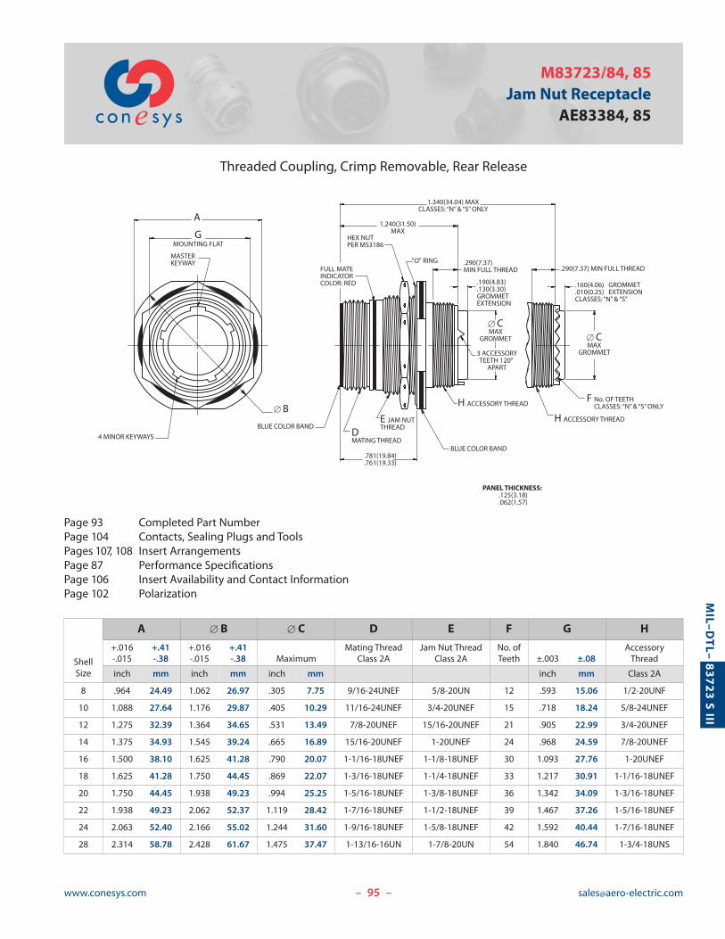
M83723/84, 85Jam Nut Receptacle
AE83384, 85
Threaded Coupling, Crimp Removable, Rear Release
– –
Page 93 Completed Part NumberPage 104 Contacts, Sealing Plugs and ToolsPages 107, 108 Insert ArrangementsPage 87 Performance SpecificationsPage 106 Insert Availability and Contact InformationPage 102 Polarization
ShellSize
A � B � C D E F G H
+.016 +.41 +.016 +.41 Mating Thread Jam Nut Thread No. of Accessory-.015 -.38 -.015 -.38 Maximum Class 2A Class 2A Teeth ±.003 ±.08 Thread
inch mm inch mm inch mm inch mm Class 2A
8 .964 24.49 1.062 26.97 .305 7.75 9/16-24UNEF 5/8-20UN 12 .593 15.06 1/2-20UNF
10 1.088 27.64 1.176 29.87 .405 10.29 11/16-24UNEF 3/4-20UNEF 15 .718 18.24 5/8-24UNEF
12 1.275 32.39 1.364 34.65 .531 13.49 7/8-20UNEF 15/16-20UNEF 21 .905 22.99 3/4-20UNEF
14 1.375 34.93 1.545 39.24 .665 16.89 15/16-20UNEF 1-20UNEF 24 .968 24.59 7/8-20UNEF
16 1.500 38.10 1.625 41.28 .790 20.07 1-1/16-18UNEF 1-1/8-18UNEF 30 1.093 27.76 1-20UNEF
18 1.625 41.28 1.750 44.45 .869 22.07 1-3/16-18UNEF 1-1/4-18UNEF 33 1.217 30.91 1-1/16-18UNEF
20 1.750 44.45 1.938 49.23 .994 25.25 1-5/16-18UNEF 1-3/8-18UNEF 36 1.342 34.09 1-3/16-18UNEF
22 1.938 49.23 2.062 52.37 1.119 28.42 1-7/16-18UNEF 1-1/2-18UNEF 39 1.467 37.26 1-5/16-18UNEF
24 2.063 52.40 2.166 55.02 1.244 31.60 1-9/16-18UNEF 1-5/8-18UNEF 42 1.592 40.44 1-7/16-18UNEF
28 2.314 58.78 2.428 61.67 1.475 37.47 1-13/16-16UN 1-7/8-20UN 54 1.840 46.74 1-3/4-18UNS
96www.conesys.com [email protected]
MIL–D
TL–
83723 S III
M83723/86, 87Straight PlugAE83386, 87
Threaded Coupling, Crimp Removable, Rear Release
– –
Page 93 Completed Part NumberPage 104 Contacts, Sealing Plugs and ToolsPages 107, 108 Insert ArrangementsPage 87 Performance SpecificationsPage 106 Insert Availability and Contact InformationPage 102 Polarization
[ B MAXCOUPLING NUT .290(7.37)
MINFULL
THREAD
4 MINOR KEYS
MASTER KEY
D MATING THREAD
[ A
BLUE COLOR BAND
3x [ .035(.89)SAFETY WIRE HOLES
1.180(29.97)MAX
3 ACCESSORY TEETHEQUALLY SPACED
E ACCESSORY THREAD
[ CMAX GROMMET
.190(4.83)
.130(3.30)GROMMETEXTENSION
ShellSize
� A � B � C D E
+.005 +.13 Mating Thread Accessory Thread-.004 -.10 Maximum Maximum Class 2B Class 2A
inch mm inch mm inch mm
8 .400 10.16 .776 19.71 .305 7.75 9/16-24UNEF 1/2-20UNF
10 .521 13.23 .906 23.01 .405 10.29 11/16-24UNEF 5/8-24UNEF
12 .691 17.55 1.078 27.38 .531 13.49 7/8-20UNEF 3/4-20UNEF
14 .760 19.30 1.141 28.98 .665 16.89 15/16-20UNEF 7/8-20UNEF
16 .887 22.53 1.266 32.16 .790 20.07 1-1/16-18UNEF 1-20UNEF
18 .993 25.22 1.375 34.93 .869 22.07 1-3/16-18UNEF 1-1/16-18UNEF
20 1.118 28.40 1.510 38.35 .994 25.25 1-5/16-18UNEF 1-3/16-18UNEF
22 1.243 31.57 1.625 41.28 1.119 28.42 1-7/16-18UNEF 1-5/16-18UNEF
24 1.368 34.75 1.760 44.70 1.244 31.60 1-9/16-18UNEF 1-7/16-18UNEF
28 1.618 41.10 2.050 52.07 1.475 37.47 1-13/16-16UN 1-3/4-18UNS
97www.conesys.com [email protected]
MIL–D
TL–
83723 S III
M83723/91, 92RFI Grounding Plug
AE83391, 92
Threaded Coupling, Crimp Removable, Rear Release
– –
Page 93 Completed Part NumberPage 104 Contacts, Sealing Plugs and ToolsPages 107, 108 Insert ArrangementsPage 87 Performance SpecificationsPage 106 Insert Availability and Contact InformationPage 102 Polarization
4 MINOR KEYS
MASTER KEY
BLUE COLOR BAND
1.180(29.97)MAX
RFI STRIP
[ B MAXCOUPLING NUT
[ CMAX
GROMMET[ A
D MATING THREAD
E ACCESSORY THREAD
3 ACCESSORY TEETHEQUALLY SPACED
3X [ .035(.89)SAFETY WIRE HOLES .290(7.37)
MINFULL
THREAD
.190(4.83)
.130(3.30)GROMMETEXTENSION
ShellSize
� A � B � C D E
+.005 +.13 Mating Thread Accessory Thread-.004 -.10 Maximum Maximum Class 2B Class 2A
inch mm inch mm inch mm
8 .400 10.16 .776 19.71 .305 7.75 9/16-24UNEF 1/2-20UNF
10 .521 13.23 .906 23.01 .405 10.29 11/16-24UNEF 5/8-24UNEF
12 .691 17.55 1.078 27.38 .531 13.49 7/8-20UNEF 3/4-20UNEF
14 .760 19.30 1.141 28.98 .665 16.89 15/16-20UNEF 7/8-20UNEF
16 .887 22.53 1.266 32.16 .790 20.07 1-1/16-18UNEF 1-20UNEF
18 .993 25.22 1.375 34.93 .869 22.07 1-3/16-18UNEF 1-1/16-18UNEF
20 1.118 28.40 1.510 38.35 .994 25.25 1-5/16-18UNEF 1-3/16-18UNEF
22 1.243 31.57 1.625 41.28 1.119 28.42 1-7/16-18UNEF 1-5/16-18UNEF
24 1.368 34.75 1.760 44.70 1.244 31.60 1-9/16-18UNEF 1-7/16-18UNEF
28 1.618 41.10 2.050 52.07 1.475 37.47 1-13/16-16UN 1-3/4-18UNS
98www.conesys.com [email protected]
MIL–D
TL–
83723 S III
M83723/95, 96Self-Locking PlugAE83395, 96
Threaded Coupling, Crimp Removable, Rear Release
– –
Page 93 Completed Part NumberPage 104 Contacts, Sealing Plugs and ToolsPages 107, 108 Insert ArrangementsPage 87 Performance SpecificationsPage 106 Insert Availability and Contact InformationPage 102 Polarization
BLUE COLOR BAND
1.180(29.97)MAX
[ C MAXCOUPLING NUT
D MATING THREAD
[ A
E ACCESSORY THREAD
3 ACCESSORY TEETHEQUALLY SPACED
[ BMAX
GROMMET
.190(4.83)
.130(3.30)GROMMETEXTENSION
.290(7.37) MINFULL
THREAD
4 MINOR KEYS
MASTER KEY
ShellSize
� A � B � C D E+.005 +.13 Mating Thread Accessory Thread-.004 -.10 Maximum Maximum Class 2B Class 2A
inch mm inch mm inch mm
8 .400 10.16 .305 7.75 .832 21.13 9/16-24UNEF 1/2-20UNF
10 .521 13.23 .405 10.29 .959 24.36 11/16-24UNEF 5/8-24UNEF
12 .691 17.55 .531 13.49 1.097 27.86 7/8-20UNEF 3/4-20UNEF
14 .760 19.30 .665 16.89 1.236 31.39 15/16-20UNEF 7/8-20UNEF
16 .887 22.53 .790 20.07 1.360 34.54 1-1/16-18UNEF 1-20UNEF
18 .993 25.22 .869 22.07 1.473 37.41 1-3/16-18UNEF 1-1/16-18UNEF
20 1.118 28.40 .994 25.25 1.586 40.28 1-5/16-18UNEF 1-3/16-18UNEF
22 1.243 31.57 1.119 28.42 1.703 43.26 1-7/16-18UNEF 1-5/16-18UNEF
24 1.368 34.75 1.244 31.60 1.846 46.89 1-9/16-18UNEF 1-7/16-18UNEF
28 1.618 41.10 1.475 37.47 2.278 57.86 1-13/16-16UN 1-3/4-18UNS
99www.conesys.com [email protected]
MIL–D
TL–
83723 S III
M83723/97, 98Self-Locking, RFI Grounding Plug
AE83397, 98
Threaded Coupling, Crimp Removable, Rear Release
– –
Page 93 Completed Part NumberPage 104 Contacts, Sealing Plugs and ToolsPages 107, 108 Insert ArrangementsPage 87 Performance SpecificationsPage 106 Insert Availability and Contact InformationPage 102 Polarization
.160(4.06)
.010(0.25)GROMMETEXTENSION
4 MINOR KEYS
BLUE COLOR BAND
F ACCESSORY THREAD
BNUMBER OF TEETH
1.280(32.51)MAX
MASTER KEY
RFI STRIP
[ D MAXCOUPLING NUT
E MATING THREAD
[ A[ CMAX
GROMMET
.290(7.37) MINFULL
THREAD
ShellSize
� A B � C � D E F
+.005 +.13 No. of Mating Thread Accessory Thread-.004 -.10 Teeth Maximum Maximum Class 2B Class 2A
inch mm inch mm inch mm
8 .400 10.16 12 .305 7.75 .967 24.56 9/16-24UNEF 1/2-20UNF
10 .521 13.23 15 .405 10.29 1.093 27.76 11/16-24UNEF 5/8-24UNEF
12 .691 17.55 21 .531 13.49 1.170 29.72 7/8-20UNEF 3/4-20UNEF
14 .760 19.30 24 .665 16.89 1.310 33.27 15/16-20UNEF 7/8-20UNEF
16 .887 22.53 30 .790 20.07 1.500 38.10 1-1/16-18UNEF 1-20UNEF
18 .993 25.22 33 .869 22.07 1.562 39.67 1-3/16-18UNEF 1-1/16-18UNEF
20 1.118 28.40 36 .994 25.25 1.710 43.43 1-5/16-18UNEF 1-3/16-18UNEF
22 1.243 31.57 39 1.119 28.42 1.812 46.02 1-7/16-18UNEF 1-5/16-18UNEF
24 1.368 34.75 42 1.244 31.60 1.948 49.48 1-9/16-18UNEF 1-7/16-18UNEF
28 1.618 41.10 54 1.475 37.47 2.278 57.86 1-13/16-16UN 1-3/4-18UNS
100www.conesys.com [email protected]
MIL–D
TL–
83723 S III
M83723/68, 69Lanyard Release, Quick-Disconnect PlugAE83368, 69
Quick-Disconnect, Threaded Coupling, Crimp Removable, Rear Release
– –
Page 93 Completed Part NumberPage 104 Contacts, Sealing Plugs and ToolsPages 107, 108 Insert ArrangementsPage 87 Performance SpecificationsPage 106 Insert Availability and Contact InformationPage 102 Polarization
Note 1:M83723/70 receptacle adapter (page 101) is requiredto mate the Quick-Disconnect Plug with a receptacle.
Note 2: Not available in shell size 8.
C ACCESSORY THREAD
7.500(190.50)MAX
[ AMAX
[ D
MASTERKEY
1.180(29.97)MAX
.190(4.83)
.130(3.30) GROMMET EXTENSION
BLUE COLOR BAND
[ B MAX GROMMET
3 ACCESSORY TEETHEQUALLY SPACED
LENGTH TO BE MEASURED WITH A[ .750(19.05)±.060(1.52) BAR TO PULLLANYARD TAUT
4 MINOR KEYS
ShellSize
� A � B C � D
Accessory ThreadMaximum Maximum Class 2A
inch mm inch mm inch mm
10 1.240 31.50 .405 10.29 5/8-24UNEF .526/.517 13.36/13.13
12 1.432 36.37 .531 13.49 3/4-20UNEF .696/.687 17.68/17.45
14 1.490 37.85 .665 16.89 7/8-20UNEF .765/.756 19.43/19.20
16 1.711 43.46 .790 20.07 1-20UNEF .892/.883 22.66/22.43
18 1.815 46.10 .869 22.07 1-1/16-18UNEF .998/.989 25.35/25.12
20 1.962 49.83 .994 25.25 1-3/16-18UNEF 1.123/1.114 28.52/28.30
22 2.070 52.58 1.119 28.42 1-5/16-18UNEF 1.248/1.239 31.70/31.47
24 2.195 55.75 1.244 31.60 1-7/16-18UNEF 1.373/1.364 34.87/34.65
101www.conesys.com [email protected]
MIL–D
TL–
83723 S III
M83723/70Receptacle Adapter, Quick-Disconnect
AE83370
Quick-Disconnect (Push-Pull) Receptacle Adapter
– –
COLOR BAND
D THREAD
[ B[ A
[ C
[ E
.442(11.23)±.005(.13)
Note: The adapter is required to mate the Lanyard Releaseand Push-Pull Quick-Disconnect plugs (M83723/66 thru 69)with M83723/82, 83, 84, 85, 88, 89 and 90 threaded couplingreceptacles. Use compatible thread seizing compound topermanently secure to the receptacle.
ShellSize
D � A � B � C � E
Coupling ThreadClass 2B ±.002 ±.05 ±.002 ±.05 ±.002 ±.05 ±.005 ±.13
inch mm inch mm inch mm inch mm
8 9/16-24UNEF .605 15.37 .577 14.66 .687 17.45 .525 13.34
10 11/16-24UNEF .730 18.54 .712 18.08 .812 20.62 .650 16.51
12 7/8-20UNEF .917 23.29 .892 22.66 .999 25.37 .840 21.34
14 15/16-20UNEF .980 24.89 .952 24.18 1.062 26.97 .900 22.86
16 1-1/16-18UNEF 1.105 28.07 1.077 27.36 1.187 30.15 1.025 26.04
18 1-3/16-18UNEF 1.230 31.24 1.202 30.53 1.328 33.73 1.150 29.21
20 1-5/16-18UNEF 1.355 34.42 1.327 33.71 1.453 36.91 1.275 32.39
22 1-7/16-18UNEF 1.480 37.59 1.452 36.88 1.578 40.08 1.400 35.56
24 1-9/16-18UNEF 1.605 40.77 1.577 40.06 1.703 43.26 1.525 38.74
Mil Prefix M83723/ 70 W 10
Aero Prefix AE833 70 W 10Specification Sheet (Shell type)
70 = Receptacle adapter, quick-disconnect
Class (Material and Finish)A = Aluminum shell, black anodized finsih
G = Stainless steel shell, passivated
R = Aluminum shell, elctroless nickel finish
W = Aluminum shell, cadmium olive drab over nickel base
Shell Size8, 10, 12, 14, 16, 18, 20, 22 or 24
102www.conesys.com [email protected]
MIL–D
TL–
83723 S III
MIL-DTL-83723 Series IIIPolarization (Shell Keying, Insert Clocking)Bayonet and Threaded
Shell Keying Insert Clocking
– –
Notes:1. In the normal position (N), the insert centerline coin-
cides with the centerline of the master keyway (key) ofthe shell. E = 0°.
2. In the alternate keying positions (6, 7, 8, 9 and Y), theminor keyways (keys) are positioned with reference tomaster keyway (key) as indicated in the keying positiontable below.
3. In the alternate insert clocking positions (1, 2, 3, 4 and5), the pin insert (viewing from the mating side) isrotated counter-clockwise relative to the centerline of themaster keyway (key) of the shell. The socket insert isrotated clockwise.
* Per MIL-STD-1554, keyed position Y and clocked positions 1, 2, 3, 4and 5 are not available in shell size 8.
** Shell size 28 is not from military standard. It is only availabe inthreaded family to Aero-Electric part number.
† Per MIL-STD-1554, insert positions 1 thru 5 are inactive for newdesign.
Note: Alternate positions “Z” and “10” are cancelled andsuperseded by Position “Y”.
ShellSize
Polarizing Key/Keyway Positions Insert Position
Position A° B° C° D° E°
8*, 10
N 105 140 215 265 0
6 102 132 248 320 0
7 80 118 230 312 0
8 35 140 205 275 0
9 64 155 234 304 0
10 only Y 25 115 220 270 0
12 thru 24, 28**
N 105 140 215 265 0
6 18 149 192 259 0
7 92 152 222 342 0
8 84 152 204 334 0
9 24 135 189 240 0
Y 98 152 268 338 0
10 thru 24
1† 105 140 215 265 10
2† 105 140 215 265 20
3† 105 140 215 265 30
4† 105 140 215 265 40
5† 105 140 215 265 50
INSERTVERTICALCENTERLINE
PIN INSERTMATING FACE
(SOCKET INSERT IS OPPOSITE)
ENGAGING FACE VIEW FOR RECEPTACLE SHELL KEYWAYS (PLUG SHELL KEYS, OPPOSITE)
MASTERKEYWAY(KEY)OF SHELL
E°
C°
B°
D°
A°
MASTERKEYWAY
103www.conesys.com [email protected]
MIL–D
TL–
83723 S III
MIL-DTL-83723 Series III, Bayonet and ThreadedFlange and Jam Nut Receptacles
Panel Cutouts
Panel Cutouts
– –
L
[ LL[ J
S
[ Z
Flange and Jam Nut Mounting Dimensions
Panel Thickness
* Includes screw-head
Receptacle Type Rear Mounting Front Mountinginch mm inch mm
Wall Mount Receptacle, Bayonet .250 max* 6.36 max* .125 max 3.18 max
Wall Mount Receptacle, Threaded .125 max 3.18 max .125 max 3.18 max
Jam Nut Mount (Bayonet & Threaded) .062/.125 1.57/3.18 — —
ShellSize
L � J � J � LL S � Z
For Back Mounting For Front Mounting +.000 +.00(TP) Minimum Minimum -.009 -.23 ±.005 ±.13 ±.005 ±.13
inch mm inch mm inch mm inch mm inch mm inch mm
8 .594 15.09 .620 15.75 .510 12.95 .125 3.18 .605 15.37 .635 16.13
10 .719 18.26 .748 19.00 .635 16.13 .125 3.18 .730 18.54 .760 19.30
12 .812 20.62 .918 23.32 .760 19.30 .125 3.18 .917 23.29 .947 24.05
14 .906 23.01 .988 25.10 .885 22.48 .125 3.18 .980 24.89 1.010 25.65
16 .969 24.61 1.114 28.30 1.010 25.65 .125 3.18 1.105 28.07 1.135 28.83
18 1.062 26.97 1.220 30.99 1.072 27.23 .125 3.18 1.229 31.22 1.260 32.00
20 1.156 29.36 1.346 34.19 1.197 30.40 .125 3.18 1.354 34.39 1.385 35.18
22 1.250 31.75 1.470 37.34 1.322 33.58 .125 3.18 1.479 37.57 1.510 38.35
24 1.375 34.93 1.596 40.54 1.442 36.63 .154 3.91 1.604 40.74 1.635 41.53
104www.conesys.com [email protected]
MIL–D
TL–
83723 S III
MIL-DTL-83723Contacts, Tools and Seal PlugsSeries III
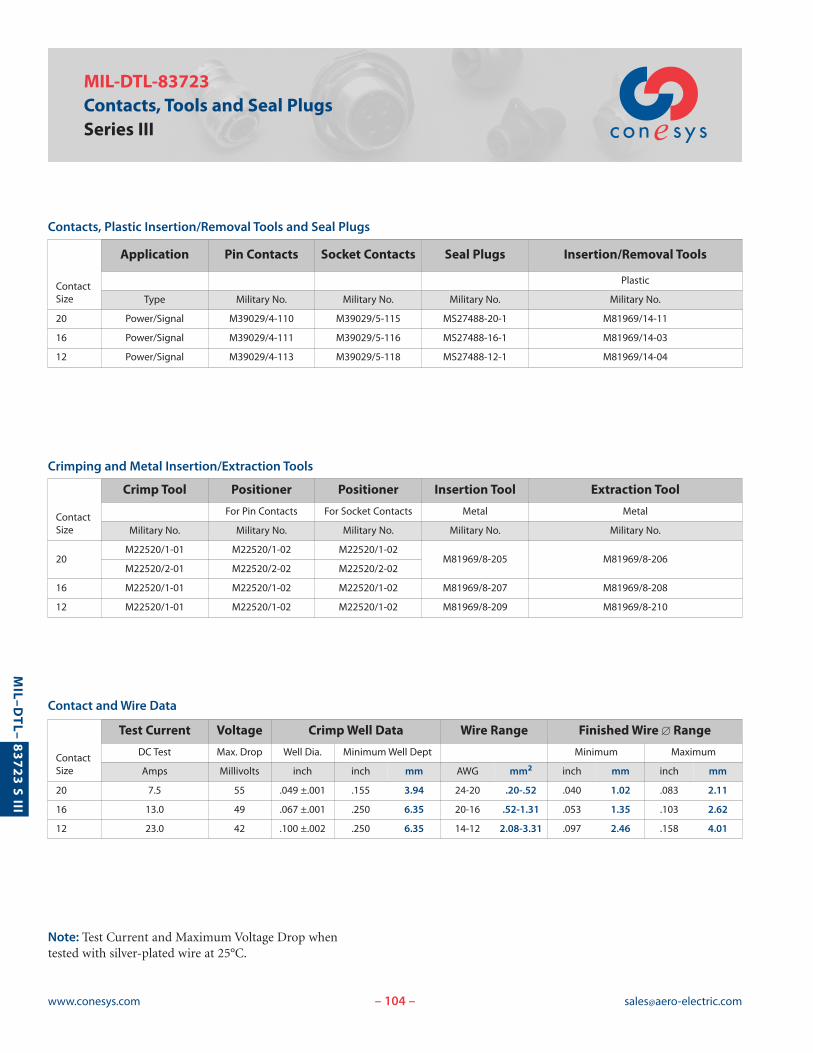
Contacts, Plastic Insertion/Removal Tools and Seal Plugs
Crimping and Metal Insertion/Extraction Tools
Contact and Wire Data
– –
Note: Test Current and Maximum Voltage Drop whentested with silver-plated wire at 25°C.
ContactSize
Application Pin Contacts Socket Contacts Seal Plugs Insertion/Removal Tools
Plastic
Type Military No. Military No. Military No. Military No.
20 Power/Signal M39029/4-110 M39029/5-115 MS27488-20-1 M81969/14-11
16 Power/Signal M39029/4-111 M39029/5-116 MS27488-16-1 M81969/14-03
12 Power/Signal M39029/4-113 M39029/5-118 MS27488-12-1 M81969/14-04
ContactSize
Crimp Tool Positioner Positioner Insertion Tool Extraction Tool
For Pin Contacts For Socket Contacts Metal Metal
Military No. Military No. Military No. Military No. Military No.
20M22520/1-01 M22520/1-02 M22520/1-02
M81969/8-205 M81969/8-206M22520/2-01 M22520/2-02 M22520/2-02
16 M22520/1-01 M22520/1-02 M22520/1-02 M81969/8-207 M81969/8-208
12 M22520/1-01 M22520/1-02 M22520/1-02 M81969/8-209 M81969/8-210
ContactSize
Test Current Voltage Crimp Well Data Wire Range Finished Wire � Range
DC Test Max. Drop Well Dia. Minimum Well Dept Minimum Maximum
Amps Millivolts inch inch mm AWG mm2 inch mm inch mm
20 7.5 55 .049 ±.001 .155 3.94 24-20 .20-.52 .040 1.02 .083 2.11
16 13.0 49 .067 ±.001 .250 6.35 20-16 .52-1.31 .053 1.35 .103 2.62
12 23.0 42 .100 ±.002 .250 6.35 14-12 2.08-3.31 .097 2.46 .158 4.01
105www.conesys.com [email protected]
MIL–D
TL–
83723 S III
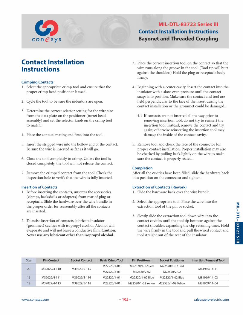
MIL-DTL-83723 Series IIIContact Installation InstructionsBayonet and Threaded Coupling
– –
Contact InstallationInstructions
Crimping Contacts 1. Select the appropriate crimp tool and ensure that the
proper crimp head positioner is used.
2. Cycle the tool to be sure the indentors are open.
3. Determine the correct selector setting for the wire sizefrom the data plate on the positioner (turret head assembly) and set the selector knob on the crimp tool to match.
4. Place the contact, mating end first, into the tool.
5. Insert the stripped wire into the hollow end of the contact.Be sure the wire is inserted as far as it will go.
6. Close the tool completely to crimp. Unless the tool isclosed completely, the tool will not release the contact.
7. Remove the crimped contact from the tool. Check theinspection hole to verify that the wire is fully inserted.
Insertion of Contacts1. Before inserting the contacts, unscrew the accessories
(clamps, backshells or adapters) from rear of plug orreceptacle. Slide the hardware over the wire bundle in the proper order for reassembly after all the contacts are inserted.
2. To assist insertion of contacts, lubricate insulator (grommet) cavities with isopropyl alcohol. Alcohol willevaporate and will not leave a conductive film. Caution:Never use any lubricant other than isopropyl alcohol.
3. Place the correct insertion tool on the contact so that thewire runs along the groove in the tool. (Tool tip will buttagainst the shoulder.) Hold the plug or receptacle bodyfirmly.
4. Beginning with a center cavity, insert the contact into theinsulator with a slow, even pressure until the contactsnaps into position. Make sure the contact and tool areheld perpendicular to the face of the insert during thecontact installation or the grommet could be damaged.
4.1 If contacts are not inserted all the way prior toremoving insertion tool, do not try to reinsert theinsertion tool. Instead, remove the contact and tryagain; otherwise reinserting the insertion tool maydamage the inside of the contact cavity.
5. Remove tool and check the face of the connector forproper contact installation. Proper installation may alsobe checked by pulling back lightly on the wire to makesure the contact is properly seated.
CompletionAfter all the cavities have been filled, slide the hardware backinto position on the connector and tighten.
Extraction of Contacts (Rework)1. Slide the hardware back over the wire bundle.
2. Select the appropriate tool. Place the wire into theextraction tool of the pin or socket.
3. Slowly slide the extraction tool down wire into the contact cavities until the tool tip bottoms against thecontact shoulder, expanding the clip retaining tines. Holdthe wire firmly in the tool and pull the wired contact andtool straight out of the rear of the insulator.
Size Pin Contact Socket Contact Basic Crimp Tool Pin Positioner Socket Positioner Insertion/Removal Tool
20 M39029/4-110 M39029/5-115M22520/1-01 M22520/1-02 Red M22520/1-02 Red
M81969/14-11M22520/2-01 M22520/2-02 M22520/2-02
16 M39029/4-111 M39029/5-116 M22520/1-01 M22520/1-02 Blue M22520/1-02 Blue M81969/14-03
12 M39029/4-113 M39029/5-118 M22520/1-01 M22520/1-02 Yellow M22520/1-02 Yellow M81969/14-04
106www.conesys.com [email protected]
MIL–D
TL–
83723 S III
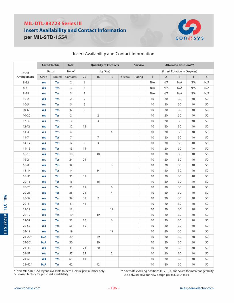
MIL-DTL-83723 Series IIIInsert Availability and Contact Informationper MIL-STD-1554
Insert Availability and Contact Information
– –
* Non MIL-STD-1554 layout, available to Aero-Electric part number only.� Consult factory for pin insert availablility.
** Alternate clocking positions (1, 2, 3, 4, and 5) are for interchangeabilityuse only. Inactive for new design per MIL-STD-1554.
InsertArrangement
Aero-Electric Total Quantity of Contacts Service Alternate Positions**
Status No. of (by Size) (Insert Rotation in Degrees)
QPL'd Tooled Contacts 20 16 12 # 8coax Rating 1 2 3 4 5
8-2� Yes Yes 2 2 I N/A N/A N/A N/A N/A
8-3 Yes Yes 3 3 I N/A N/A N/A N/A N/A
8-98 Yes Yes 3 3 I N/A N/A N/A N/A N/A
10-2 Yes Yes 2 2 I 10 20 30 40 50
10-5 Yes Yes 5 5 I 10 20 30 40 50
10-6 Yes Yes 6 6 I 10 20 30 40 50
10-20 Yes Yes 2 2 I 10 20 30 40 50
12-3 Yes Yes 3 3 I 10 20 30 40 50
12-12 Yes Yes 12 12 I 10 20 30 40 50
14-4 Yes Yes 4 4 I 10 20 30 40 50
14-7 Yes Yes 7 7 I 10 20 30 40 50
14-12 Yes Yes 12 9 3 I 10 20 30 40 50
14-15 Yes Yes 15 15 I 10 20 30 40 50
16-10 Yes Yes 10 10 I 10 20 30 40 50
16-24 Yes Yes 24 24 I 10 20 30 40 50
18-8 Yes Yes 8 8 I 10 20 30 40 50
18-14 Yes Yes 14 14 I 10 20 30 40 50
18-31 Yes Yes 31 31 I 10 20 30 40 50
20-16 Yes Yes 16 16 I 10 20 30 40 50
20-25 Yes Yes 25 19 6 I 10 20 30 40 50
20-28 Yes Yes 28 24 4 I 10 20 30 40 50
20-39 Yes Yes 39 37 2 I 10 20 30 40 50
20-41 Yes Yes 41 41 I 10 20 30 40 50
22-12 Yes Yes 12 12 I 10 20 30 40 50
22-19 Yes Yes 19 19 I 10 20 30 40 50
22-32 Yes Yes 32 26 6 I 10 20 30 40 50
22-55 Yes Yes 55 55 I 10 20 30 40 50
24-19 Yes Yes 19 19 I 10 20 30 40 50
24-29* N/A Yes 29 29 I 10 20 30 40 50
24-30* N/A Yes 30 30 I 10 20 30 40 50
24-43 Yes Yes 43 23 20 I 10 20 30 40 50
24-57 Yes Yes 57 55 2 I 10 20 30 40 50
24-61 Yes Yes 61 61 I 10 20 30 40 50
28-42* N/A Yes 42 42 I 10 20 30 40 50
2
13
2
11
2
12
3 4
5
6
21
802*2 # 20
I
8033 # 20
I
8983 # 20
I
10022 # 20
I
10055 # 20
I
10066 # 20
I
10202 # 16
I
12033 # 16
I
121212 # 20
I
14044 # 12
I
14077 # 16
I
14129 # 20, 3 # 16
I
181414 # 16
I
183131 # 20
I
201616 # 16
I
202519 # 20, 6 # 12
I
202824 # 20, 4 # 12
I
203937 # 20, 2 # 16
I
204141 # 20
I
221212 # 12
I
1
31
1
25
1
3
1
5
1
2 3
1
4
1
7
18088 # 12
I
1
8
1
12
1
12
141515 # 20
I
1
15
161010 # 16
I
1
10
1
14
1
12
1
39
162424 # 20
I
1
24
1
16
1
28
1
41
107www.conesys.com [email protected]
MIL–D
TL–
83723 S III
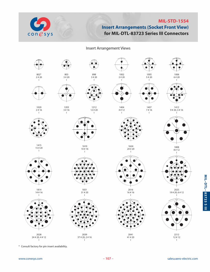
MIL-STD-1554Insert Arrangements (Socket Front View)for MIL-DTL-83723 Series III Connectors
Insert Arrangement Views
– –
* Consult factory for pin insert availability.
108www.conesys.com [email protected]
MIL–D
TL–
83723 S III
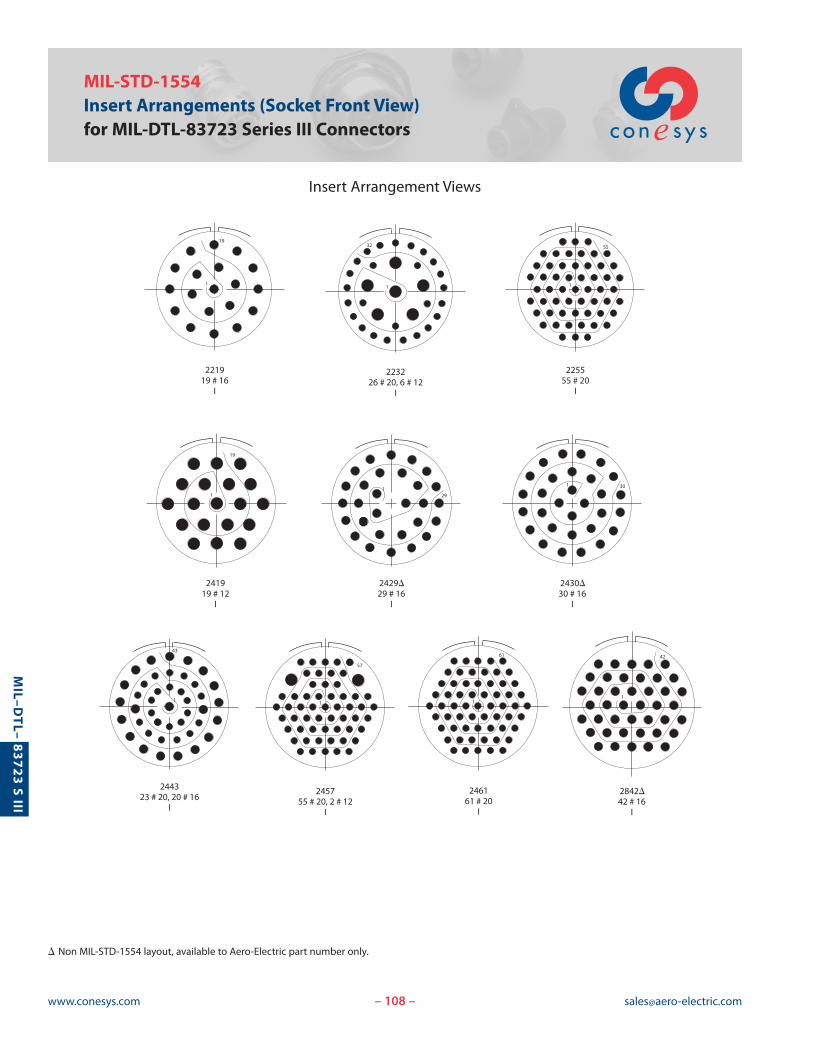
MIL-STD-1554Insert Arrangements (Socket Front View)for MIL-DTL-83723 Series III Connectors
Insert Arrangement Views
– –
221919 # 16
I
241919 # 12
I
223226 # 20, 6 # 12
I
244323 # 20, 20 # 16
I
2430D30 # 16
I
2429D29 # 16
I
225555 # 20
I
245755 # 20, 2 # 12
I
246161 # 20
I
2842D42 # 16
I
19
1 1
32
1
43
291
1 30
1
55
1
61
1
57
1
42
1
19
� Non MIL-STD-1554 layout, available to Aero-Electric part number only.