Embed Size (px)
Citation preview

2D Scan Engine
MDI-3100
MDI-3100
This document provides instructions for installing the MDI-3100 imager scan engine. Integration Guide

MDI-3100 Integration guide
All information subject to change without notice.
Document History Model Number: MDI-3100 Specification Number: TS12030
Edition: 1.1 Original Spec Number: TS11039
Date: 2012-09-18
Copyright 2012 Opticon. All rights reserved. This manual may not, in whole or in part, be copied, photocopied, reproduced, translated or converted to any electronic or machine readable form without prior written consent of Opticon.
Limited Warranty and Disclaimers PLEASE READ THIS MANUAL CAREFULLY BEFORE INSTALLING OR USING THE PRODUCT. Serial Number A serial number appears on all Opticon products. This official registration number is directly related to the device purchased. Do not remove the serial number from your Opticon device. Removing the serial number voids the warranty.
Warranty Unless otherwise agreed in a written contract, all Opticon products are warranted against defects in materials and workmanship for two years after purchase. Opticon will repair or, at its option, replace products that are defective in materials or workmanship with proper use during the warranty period. Opticon is not liable for damages caused by modifications made by a customer. In such cases, standard repair charges will apply. If a product is returned under warranty and no defect is found, standard repair charges will apply. Opticon assumes no liability for any direct, indirect, consequential or incidental damages arising out of use or inability to use both the hardware and software, even if Opticon has been informed about the possibility of such damages.
Packaging The packing materials are recyclable. We recommend that you save all packing material to use should you need to transport your scanner or send it for service. Damage caused by improper packaging during shipment is not covered by the warranty.
Trademarks Trademarks used are the property of their respective owners. Opticon Inc. and Opticon Sensors Europe B.V. are wholly owned subsidiaries of OPTOELECTRONICS Co., Ltd., 12-17, Tsukagoshi 4-chome, Warabi-shi, Saitama, Japan 335-0002. TEL +81-(0) 48-446-1183; FAX +81-(0) 48-446-1184
SUPPORT
USA Europe Phone: 800-636-0090
Email: [email protected] Email: [email protected]
Web: www.opticonusa.com Web: www.opticon.com

MDI-3100 Integration guide
Revision History
Specification No. : TS12030 Product name : MDI-3100
Edition Date Page Section Description of Changes
First 2012/07/17 - - Initial release

MDI-3100 Integration guide
2.1. Exit Window Material .....................................................................................................................32.2. Exit Window Placement.................................................................................................................4
3. Exit Window Size ........................................................................................................................ 53.1. Window Size and Optical Path Clearance .....................................................................................63.2. Optical Path...................................................................................................................................73.3. Field of View..................................................................................................................................83.4. Scanned Media and Placement.....................................................................................................9
4. Installation................................................................................................................................. 104.1. Installation Conditions .................................................................................................................114.2. Cable and Connector...................................................................................................................124.3. Handling Requirements ...............................................................................................................13
5. Mechanical Drawings ............................................................................................................... 145.1. MDI-3100-SR (Standard Range Focus) ......................................................................................145.2. MDI-3100-HD (High Density Focus) ............................................................................................15
Table of contents Page
1. Abstract ....................................................................................................................................... 122. Exit Window Material and Placement .......................................................................................

MDI-3100 Integration Guide
1
1. Abstract This guide provides instructions for installing the MDI-3100-SR/HD (hereafter called “scan engine”). In order to maximize its performance and prevent troubles from happening, read this integration guide carefully and design your integration devices in accordance with it. ・Exit Window Material and Placement : Layout design to prevent the LED illumination from
reflecting off the exit window
・Exit Window Size : Ensuring clearance for optical path of imaging and LED illumination
・Installation : Detailed installation instructions This integration guide is for the following models:
MDI-3100-SR : Standard range model
MDI-3100-HD : High density model
* The conditions described herein are ‘recommended’ conditions. Therefore, make sure to check
the images with image-capturing tools or the like.

MDI-3100 Integration Guide
2
2. Exit Window Material and Placement Reflection of the LED illumination from the exit window can occur depending on the window material and placement. This chapter describes the material and the distance and inclination limitations for the exit window.
LED illumination reflecting off the exit window
The chapter contains:
2.1. Exit Window Material 2.2. Exit Window Placement

MDI-3100 Integration Guide
3
2.1. Exit Window Material The following items are recommended for selecting the exit window to prevent the reflection of the LED illumination from the exit window and the degradation of image contrast by scratches and dirt.
For the best optical quality, use an acrylic material (cast or extruded) for the exit window.
Select a high-quality achromatic acrylic material with a smooth, flat surface and no scratches or dents.
It is recommended that the acrylic material is 1 mm thick and has an anti-reflective (AR)
coating applied to both sides of the exit window.
It is recommended to apply an anti-scratch coating to the surface of the exit window to protect it from scratches during operation.
Hard coated acrylic sheets are readily available. Such a coating greatly enhances anti-
scratch properties without degrading the optical characteristics of the acrylic material.
To protect the exit window from dust, stains, and scratches during assembly, a protective sheet was attached. This should be removed before operation.
After removing the protective sheet, use an ion-blower or other method to remove any dust
that may have been attracted by static electricity. Recommended acrylic material: Nitto Jushi Kogyo Co., Ltd. : “Clarex Precision Thin Sheet” MITSUBISHI RAYON CO., LTD. : “Shinkolite”

MDI-3100 Integration Guide
4
2.2. Exit Window Placement The exit window must be positioned to accommodate the limitations of distance and inclination in order to prevent the LED illumination from reflecting off the window. Design the layout within the range specified in the following diagram and associated table.
Figure 1: Exit Window Placement
The following shows the recommended mounting position of the window with ‘both sides AR coated’ and ‘non AR coated’.
<Measurement conditions> Window : 1 mm acrylic sheet Conditions : Visually check reflections when taking images with the scan engine in a darkroom with no light
source and no reflection object around. [Both sides AR coated]l
L [mm] 1.0 1.5 2.0 2.5 3.0 3.5 4.0 4.5 5.0 6.0 7.0 8.0 9.0 10.0
θCW [deg] 0° ≧0° ≧0° ≧25°≦5° ≧30° - - - - - - - - -
θCCW [deg] 0° ≧0° ≧0° ≧0° ≧5° ≧10° ≧10° ≧20° ≧20° ≧20° ≧20° ≧20° ≧20° ≧20°
[Non AR coated]
L [mm] 1.0 1.5 2.0 2.5 3.0 3.5 4.0 4.5 5.0 6.0 7.0 8.0 9.0 10.0
θCW [deg] 0° 0° - - - - - - - - - - - -
θCCW [deg] 0° ≧0° ≧10° ≧15° ≧20° ≧20° - - - - - - - -
* L = 1 mm, θ = 0° (recommended) * 1 mm or more clearance between the scan engine and the exit wind (recommended) due to the
dimensional tolerance of mounting holes * Use of AR coating (recommended). Under the above conditions the external light is not factored in. * Confirm that there is no reflection of the LED illumination from the window by acquiring images from the
scan engine.
MDI-3100 Integration Guide
5
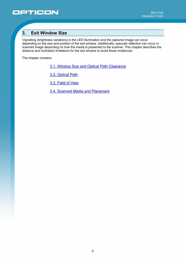
3. Exit Window Size Vignetting (brightness variations) in the LED illumination and the captured image can occur depending on the size and position of the exit window. Additionally, specular reflection can occur in scanned image depending on how the media is presented to the scanner. This chapter describes the distance and inclination limitations for the exit window to avoid those incidences. The chapter contains:
3.1. Window Size and Optical Path Clearance 3.2. Optical Path 3.3. Field of View 3.4. Scanned Media and Placement

MDI-3100 Integration Guide
6
3.1. Window Size and Optical Path Clearance With respect to the optical path depicted below, provide an exit window with sufficient clearance.
Figure 2: Window Size and Optical Path Clearance
The following tables show the conditions of the horizontal and vertical optical path clearance. [Horizontal]
L [mm] 1.0 1.5 2.0 2.5 3.0 3.5 4.0 4.5 5.0 6.0 7.0 8.0 9.0 10.0
HR [mm] ≧11.0 ≧11.5 ≧12.0 ≧12.5 ≧13.0 ≧13.5 ≧14.0 ≧14.5 ≧15.0 ≧16.0 ≧17.0 ≧18.0 ≧19.0 ≧20.0
HL [mm] ≧11.0 ≧11.5 ≧12.0 ≧12.5 ≧13.0 ≧13.5 ≧14.0 ≧14.5 ≧15.0 ≧16.0 ≧17.0 ≧18.0 ≧19.0 ≧20.0
[Vertical]
L [mm] 1.0 1.5 2.0 2.5 3.0 3.5 4.0 4.5 5.0 6.0 7.0 8.0 9.0 10.0
HR [mm] ≧3.5 ≧3.5 ≧3.5 ≧3.5 ≧3.5 ≧3.5 ≧3.5 ≧3.5 ≧3.5 ≧3.5 ≧3.5 ≧3.5 ≧3.8 ≧4.1
HL [mm] ≧5.4 ≧5.4 ≧5.4 ≧5.4 ≧5.4 ≧5.4 ≧5.4 ≧5.4 ≧5.5 ≧5.8 ≧6.1 ≧6.4 ≧6.7 ≧7.0
* The vignetting is caused by insufficient exit window size and an illumination shape is decided
depending on the window frame. Confirm them visually and by acquiring images from the scan engine in the design phase.

MDI-3100 Integration Guide
7
3.2. Optical Path Install the window with sufficient clearance for the field of view, LED illumination and LED aiming. With respect to the optical path depicted below, provide an exit window with sufficient clearance.
Figure 3: MDI-3100 Optical Path
* Refer to 3D drawings for details of the configuration of scan engine and the optical path. * It is recommended to verify the details of optical path with an actual device.
MDI-3100 Integration Guide
8
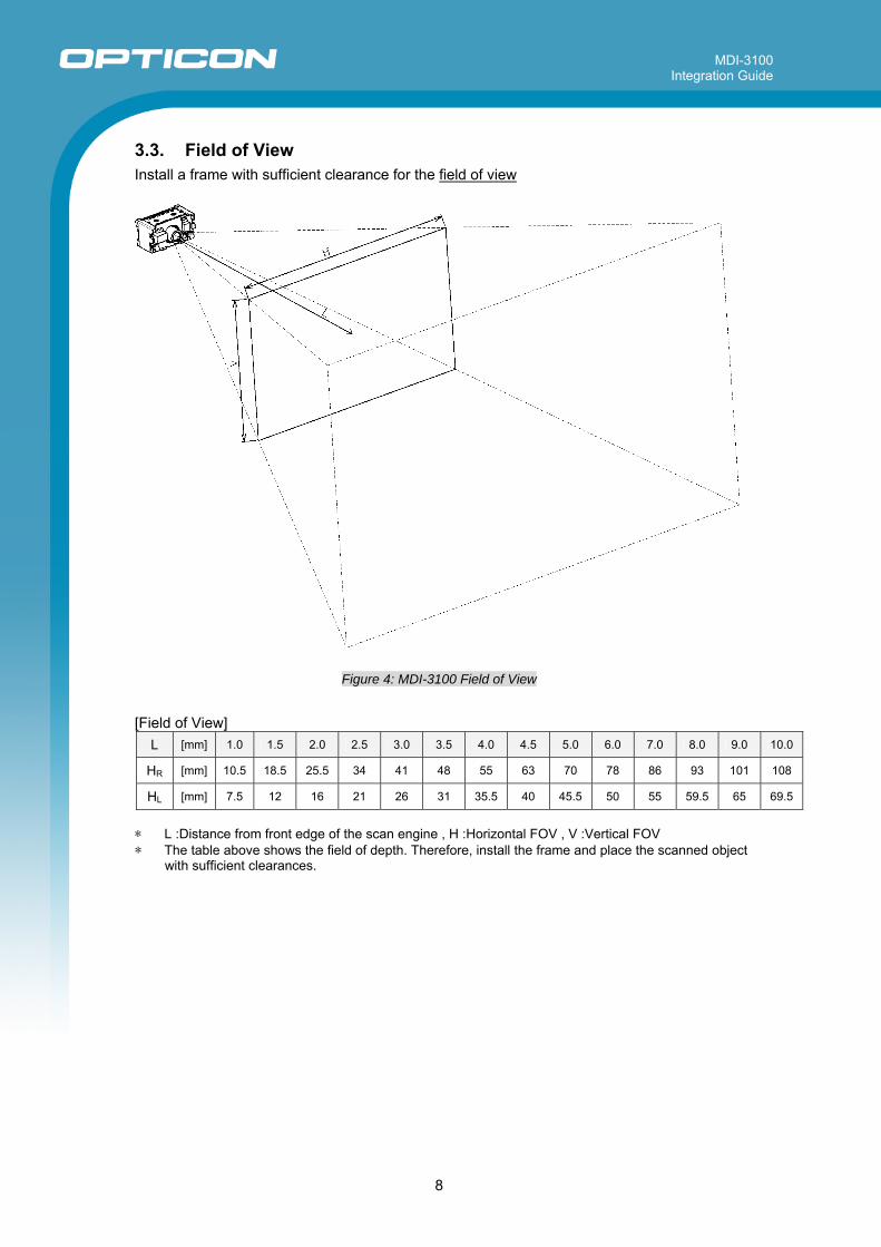
3.3. Field of View Install a frame with sufficient clearance for the field of view
Figure 4: MDI-3100 Field of View
[Field of View]
L [mm] 1.0 1.5 2.0 2.5 3.0 3.5 4.0 4.5 5.0 6.0 7.0 8.0 9.0 10.0
HR [mm] 10.5 18.5 25.5 34 41 48 55 63 70 78 86 93 101 108
HL [mm] 7.5 12 16 21 26 31 35.5 40 45.5 50 55 59.5 65 69.5
* L :Distance from front edge of the scan engine , H :Horizontal FOV , V :Vertical FOV * The table above shows the field of depth. Therefore, install the frame and place the scanned object
with sufficient clearances.

MDI-3100 Integration Guide
9
3.4. Scanned Media and Placement When an object is being scanned, there are conditions where specular reflection of the LED illumination and intense ambient light can occur easily. Glossy label: Specular reflection of the LED illumination from the scan engine can occur under certain conditions.
Solution: Specular reflection does not occur when an angle is created between the scan engine and the target label as shown in the figure below. The conditions for the occurrence of specular reflection depend on the distance L and the inclination angle θ. The recommended inclination angle is about 15 degrees. Note that when the angle becomes bigger, it will be difficult to read the target label.
Figure 5: Inclination of Scanned Target
Code displayed on LCD: Specular reflection of intense ambient light (fluorescent light, window light etc.) occurs on the LCD glass surface.
Solution: It is recommended to have a structure for blocking the intense ambient light around the scanning position.

MDI-3100 Integration Guide
10
4. Installation This chapter describes the major focus points to consider when incorporating the scan engine into your device. The chapter contains:
4.1. Installation Conditions 4.2. Cable and Connector 4.3. Handling Requirements
MDI-3100 Integration Guide
11
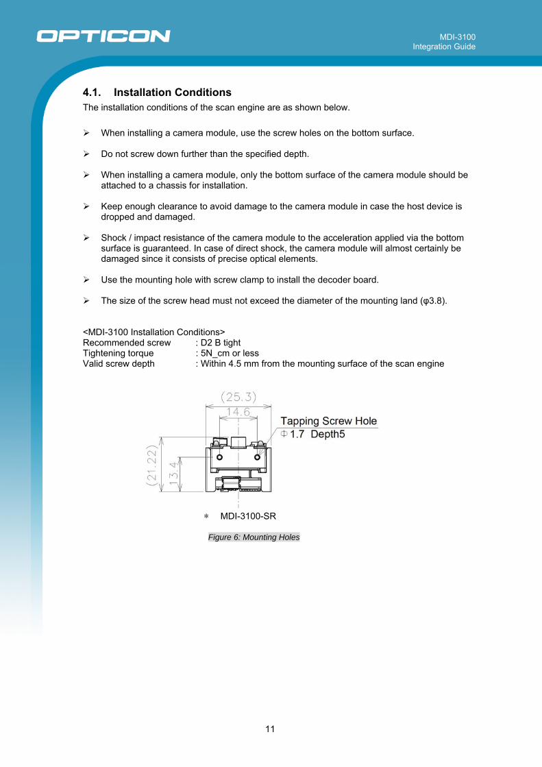
4.1. Installation Conditions The installation conditions of the scan engine are as shown below.
When installing a camera module, use the screw holes on the bottom surface.
Do not screw down further than the specified depth.
When installing a camera module, only the bottom surface of the camera module should be attached to a chassis for installation.
Keep enough clearance to avoid damage to the camera module in case the host device is
dropped and damaged.
Shock / impact resistance of the camera module to the acceleration applied via the bottom surface is guaranteed. In case of direct shock, the camera module will almost certainly be damaged since it consists of precise optical elements.
Use the mounting hole with screw clamp to install the decoder board.
The size of the screw head must not exceed the diameter of the mounting land (φ3.8).
<MDI-3100 Installation Conditions> Recommended screw : D2 B tight Tightening torque : 5N_cm or less Valid screw depth : Within 4.5 mm from the mounting surface of the scan engine
* MDI-3100-SR
Figure 6: Mounting Holes

MDI-3100 Integration Guide
12
4.2. Cable and Connector The following shows the cable and the connector to connect the scan engine and the host.
Recommended connector : IRISO 9681-12 (12pin) Recommended cable length : 50 mm (max)
Figure 7: FFC
FFC specified thickness: 0.3±0.03
Figure 8: FFC Terminal
* When using the FPC, it is recommended to use “polyimide and thermoset adhesive” as
material for the reinforcing film. * When using the FPC, verify the thickness and the dimensional tolerance of the FPC is correct.

MDI-3100 Integration Guide
13
4.3. Handling Requirements The recommended handling conditions for incorporating the scan engine into your device are as shown below.
Use anti-static measures such as a grounding strap before handling the scan engine in order
to avoid damage to the electronic components from electrostatic discharge.
Hold the scan engine only by the case. Do not touch the circuit board or the front side of the scan engine when handling it.
Do not touch the electronic components or the terminals on the circuit board.
Installation in a clean environment is recommended in order to protect the imaging lens from
dust.
Operators should wear gloves to avoid contaminating the optical elements.
Do not drop the MDI-3100.

MDI-3100 Integration Guide
14
5. Mechanical Drawings 5.1. MDI-3100-SR (Standard Range Focus)
Figure 9: MDI-3100-SR
* The depth of the HD model is 0.2 mm deeper in size than that of the SR model.
MDI-3100 Integration Guide
15
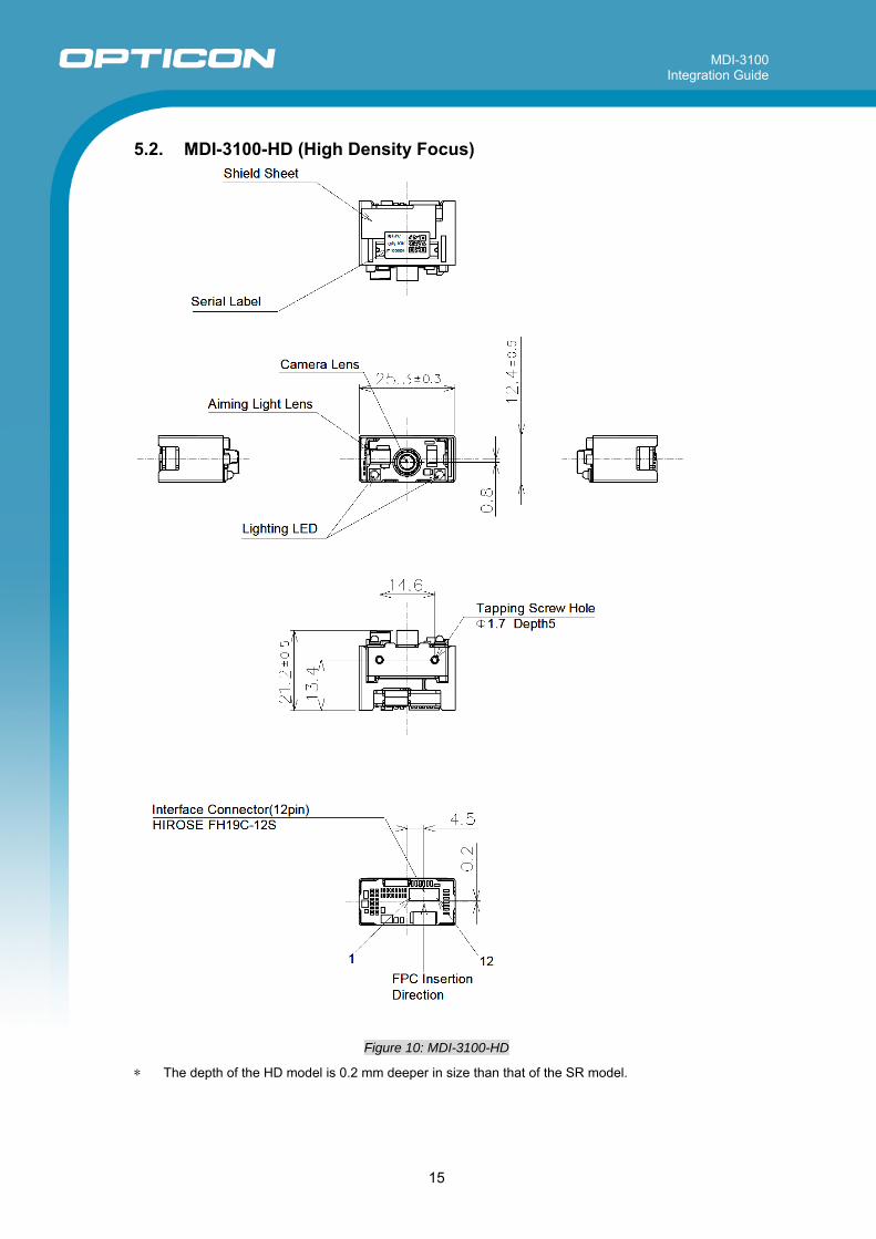
5.2. MDI-3100-HD (High Density Focus)
Figure 10: MDI-3100-HD
* The depth of the HD model is 0.2 mm deeper in size than that of the SR model.