Embed Size (px)
Citation preview
September 2015
Microwave System Path Survey Report Riverside County
Riverside PD
PROPRIETARY NOTICE: This document is the result of technical
investigations made by the engineering staff of Alcatel. The disclosure of the information herein may pertain to proprietary rights, and the furnishing
of this document does not constitute an expressed or implied license to use such materials.
Alcatel-Lucent 3400 W. Plano Parkway
Plano, Texas 75075-5802
Printed in the United States of America
TABLE OF CONTENTS
SYSTEM MAP 1.1 SCOPE OF WORK 1.2 METHOD OF SURVEY 1.3 CONSTRUCTION OF PATH PROFILES
SITE DESCRIPTIONS:
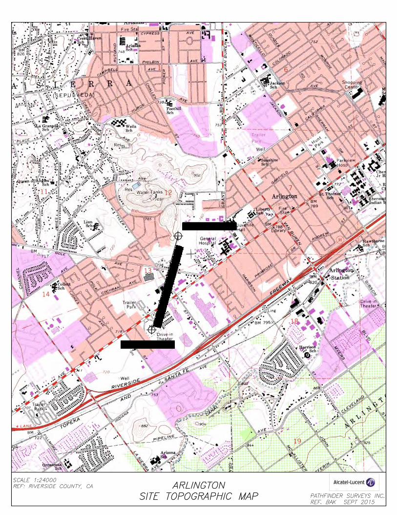
-- SITE TOPOGRAPHIC
-- SITE LOCATION MAP
-- SITE INFORMATION
-- SITE DRAWINGS
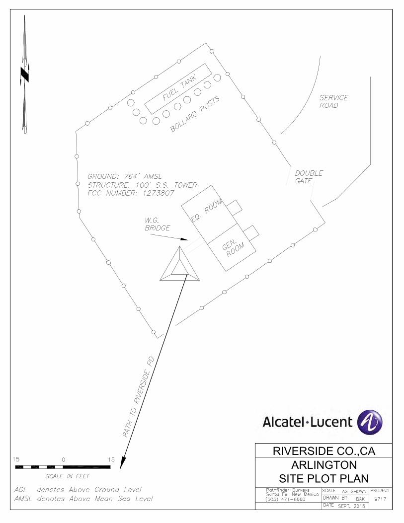
SITE PLOT PLAN
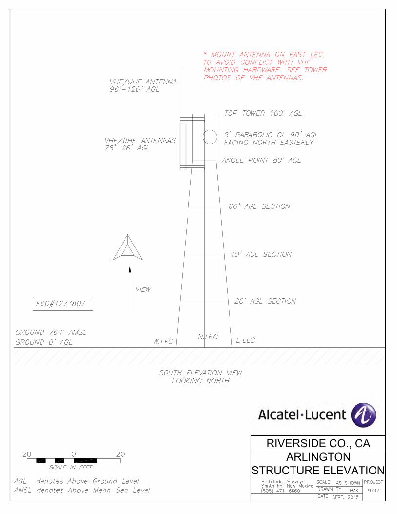
TOWER SKETCH
-- SITE PHOTOGRAPHS
PATH DESCRIPTION:
- PATH DESCRIPTION
- PATH PROFILE DATA
- PATH PHOTOGRAPHS
PATH DESIGN:
- ENGINEERING NOTES
- PATH PROFILE
- PERFORMANCE CALCULATIONS
WARRANTY
TABLE OF CONTENTS
SYSTEM MAP
1.1 SCOPE OF WORK
1.2 METHOD OF SURVEY
1.3 CONSTRUCTION OF PATH PROFILES
SITE DESCRIPTIONS:
1. Arlington
2. Riverside PD
PATH DESCRIPTIONS:
1. Riverside PD to Arlington
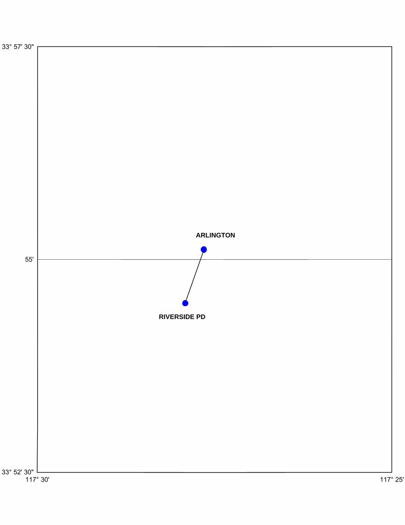
33° 52' 30"
55'
33° 57' 30"
117° 30' 117° 25'
RIVERSIDE PD
ARLINGTON

September 2015
Project 9717
STATIONFCC
NUMBER
LATITUDE
(DMS)
LONGITUDE
(DMS)
ELEVATION
(FEET)
TOWER
(FEET)TO STATION
FREQUENCY
(GHZ)
ANTENNA
CENTERLINE
(FEET)
ESTIMATED
WAVEGUIDE
(FEET)
FORWARD
AZIMUTH
(DMS)
DISTANCE
(MILES)
ARLINGTON 1273807 33 55 07.0 N 117 27 39.1 W 764 EXISTING RIVERSIDE PD 11.200 ** 98 128 199 10 02 0.768
100' S/S
RIVERSIDE PD NA 33 54 29.1 N 117 27 54.9 W 730 EXISTING ARLINGTON 11.200 32 156 19 09 53 0.768
32' ROOF MOUNT
** MOUNT ON NON-NATURAL LEG
MICROWAVE SYSTEM DATA
GEODETIC COORDINATES
NAD83
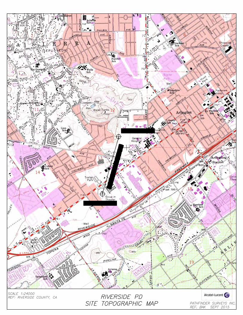
RIVERSIDE COUNTY, CA CITY OF RIVERSIDE PD
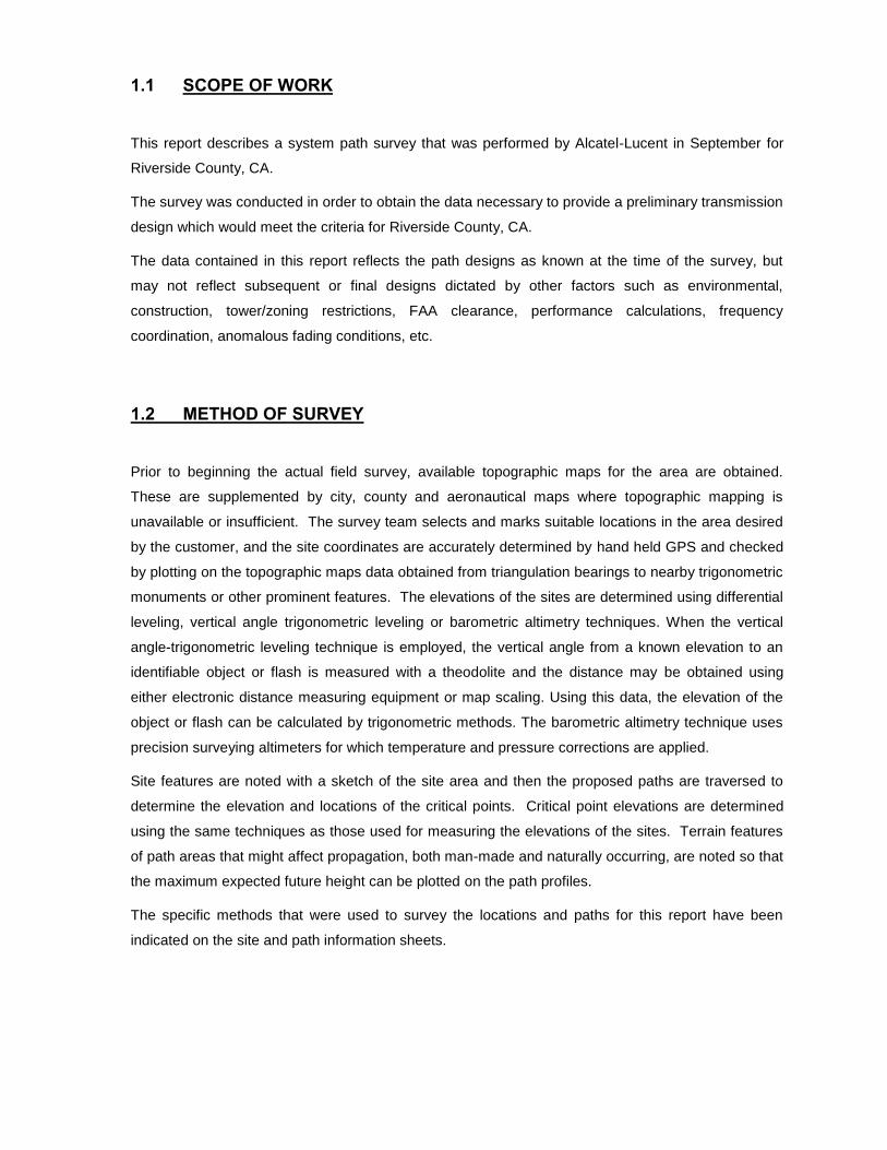
1.1 SCOPE OF WORK
This report describes a system path survey that was performed by Alcatel-Lucent in September for
Riverside County, CA.
The survey was conducted in order to obtain the data necessary to provide a preliminary transmission
design which would meet the criteria for Riverside County, CA.
The data contained in this report reflects the path designs as known at the time of the survey, but
may not reflect subsequent or final designs dictated by other factors such as environmental,
construction, tower/zoning restrictions, FAA clearance, performance calculations, frequency
coordination, anomalous fading conditions, etc.
1.2 METHOD OF SURVEY
Prior to beginning the actual field survey, available topographic maps for the area are obtained.
These are supplemented by city, county and aeronautical maps where topographic mapping is
unavailable or insufficient. The survey team selects and marks suitable locations in the area desired
by the customer, and the site coordinates are accurately determined by hand held GPS and checked
by plotting on the topographic maps data obtained from triangulation bearings to nearby trigonometric
monuments or other prominent features. The elevations of the sites are determined using differential
leveling, vertical angle trigonometric leveling or barometric altimetry techniques. When the vertical
angle-trigonometric leveling technique is employed, the vertical angle from a known elevation to an
identifiable object or flash is measured with a theodolite and the distance may be obtained using
either electronic distance measuring equipment or map scaling. Using this data, the elevation of the
object or flash can be calculated by trigonometric methods. The barometric altimetry technique uses
precision surveying altimeters for which temperature and pressure corrections are applied.
Site features are noted with a sketch of the site area and then the proposed paths are traversed to
determine the elevation and locations of the critical points. Critical point elevations are determined
using the same techniques as those used for measuring the elevations of the sites. Terrain features
of path areas that might affect propagation, both man-made and naturally occurring, are noted so that
the maximum expected future height can be plotted on the path profiles.
The specific methods that were used to survey the locations and paths for this report have been
indicated on the site and path information sheets.
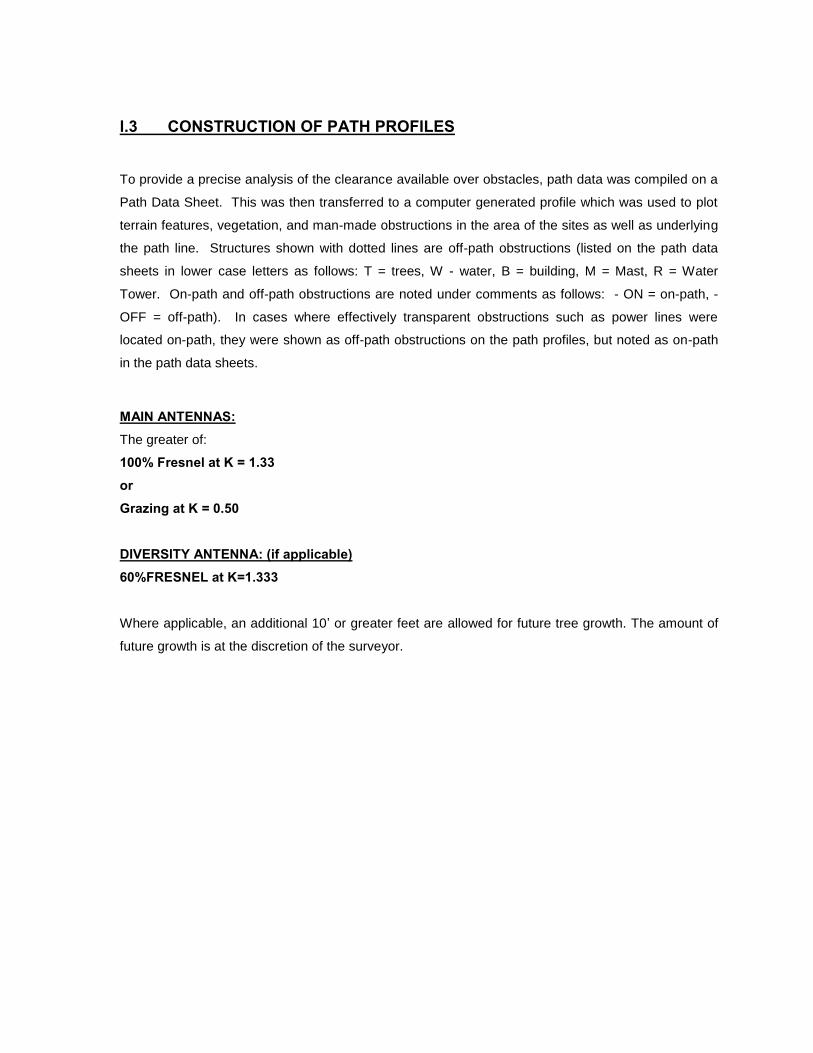
l.3 CONSTRUCTION OF PATH PROFILES
To provide a precise analysis of the clearance available over obstacles, path data was compiled on a
Path Data Sheet. This was then transferred to a computer generated profile which was used to plot
terrain features, vegetation, and man-made obstructions in the area of the sites as well as underlying
the path line. Structures shown with dotted lines are off-path obstructions (listed on the path data
sheets in lower case letters as follows: T = trees, W - water, B = building, M = Mast, R = Water
Tower. On-path and off-path obstructions are noted under comments as follows: - ON = on-path, -
OFF = off-path). In cases where effectively transparent obstructions such as power lines were
located on-path, they were shown as off-path obstructions on the path profiles, but noted as on-path
in the path data sheets.
MAIN ANTENNAS: The greater of:
100% Fresnel at K = 1.33 or Grazing at K = 0.50 DIVERSITY ANTENNA: (if applicable) 60%FRESNEL at K=1.333
Where applicable, an additional 10’ or greater feet are allowed for future tree growth. The amount of
future growth is at the discretion of the surveyor.
SITE
DESCRIPTIONS
ARLINGTON
Cook AveCook AveCook AveCook Ave
Ilex
Ct
Ilex
Ct
Ilex
Ct
Ilex
Ct
Amity
Ct
Amity
Ct
Amity
Ct
Amity
Ct
Keega
n C
Keega
n
Keega
n
Keega
n C
Tomlinson AveTomlinson AveTomlinson AveTomlinson Ave
California AveCalifornia AveCalifornia AveCalifornia Ave
Gar
deng
ate
Gar
deng
ate
Gar
deng
ate
Gar
deng
ate
Gile
s C
tG
iles
Ct
Gile
s C
tG
iles
Ct
Sun
fair
LnS
unfa
ir Ln
Sun
fair
LnS
unfa
ir Ln
Lion
head
Ave
Lion
head
Ave
Lion
head
Ave
Lion
head
Ave
Man
x C
tM
anx
Ct
Man
x C
tM
anx
Ct
Cirr
us W
ayC
irrus
Way
Cirr
us W
ayC
irrus
Way
Estrellita SEstrellita SEstrellita SEstrellita S
Bolton AvBolton ABolton ABolton Av
Tyler St
Tyler St
Tyler St
Tyler St
Selkirk S
tS
elkirk St
Selkirk S
tS
elkirk St
nson Ave
inson Ave
nson Ave
nson Ave
Mariposa A
veM
ariposa Ave
Mariposa A
veM
ariposa Ave
California A
ve
California A
ve
California A
ve
California A
ve
Rey
nold
s R
dR
eyno
lds
Rd
Rey
nold
s R
dR
eyno
lds
Rd
Har
rison
St
Har
rison
St
Har
rison
St
Har
rison
St
Sharon AveSharon AveSharon AveSharon Ave
mento Dr
mento Dr
mento Dr
mento Dr
Wagner WayWagner WayWagner WayWagner Way
Bonita Ave
Bonita Ave
Bonita Ave
Bonita Ave
Kidd StKidd StKidd StKidd St
Dawes St
Dawes St
Dawes St
Dawes St
Harrison
Harrison
Harrison
Harrison
Hole AveHole AveHole AveHole Aveyan St
yan Styan Styan St
Pen
dlet
on S
tP
endl
eton
St
Pen
dlet
on S
tP
endl
eton
St
ochran AveCochran Ave
Cochran Aveochran Ave
Magnolia Ave
Magnolia Ave
Magnolia Ave
Magnolia Ave
Tyler StTyler St
Tyler St
Tyler St
Megginson Ln
Megginson Ln
Megginson Ln
Megginson Ln
Judy Ct
Judy Ct
Judy Ct
Judy CtInez CtInez Ct
Inez Ct
Inez CtShirle
y St
Shirley St
Shirley S
t
Shirley S
t
Hughes Aly
Hughes Aly
Hughes Aly
Hughes Aly
Ross St
Ross St
Ross St
Ross St
Galleria at TylerGalleria at TylerGalleria at TylerGalleria at Tyler
Arlington
CanMap®, DMTI Spatial and the DMTI Spatial logo are trademarks of DMTI Spatial Inc., Markham, Ontario.© Garmin Ltd. or its subsidiaries 2013.© NAVTEQ Maps and NAVTEQ Traffic are trademarks of Nokia. © 2013 Nokia. All rights reserved.
1600 ft1200 ft800 ft400 ft0 ftMNTN
1/1/2010
12.5°
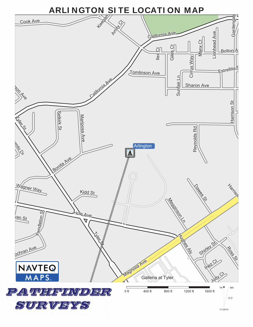
ARLINGTON SITE LOCATION MAP
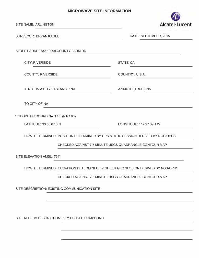
MICROWAVE SITE INFORMATION
SITE NAME: ARLINGTON
SURVEYOR: BRYAN KAGEL DATE: SEPTEMBER, 2015
STREET ADDRESS: 10099 COUNTY FARM RD
CITY: RIVERSIDE
COUNTY: RIVERSIDE COUNTRY: U.S.A.
IF NOT IN A CITY: DISTANCE: NA AZIMUTH (TRUE): NA
TO CITY OF:NA
**GEODETIC COORDINATES (NAD 83)
LATITUDE: 33 55 07.0 N LONGITUDE: 117 27 39.1 W
STATE: CA
HOW DETERMINED: POSITION DETERMINED BY GPS STATIC SESSION DERIVED BY NGS-OPUS
CHECKED AGAINST 7.5 MINUTE USGS QUADRANGLE CONTOUR MAP
SITE ELEVATION AMSL: 764'
HOW DETERMINED: ELEVATION DETERMINED BY GPS STATIC SESSION DERIVED BY NGS-OPUS
CHECKED AGAINST 7.5 MINUTE USGS QUADRANGLE CONTOUR MAP
SITE DESCRIPTION: EXISTING COMMUNICATION SITE
SITE ACCESS DESCRIPTION: KEY LOCKED COMPOUND
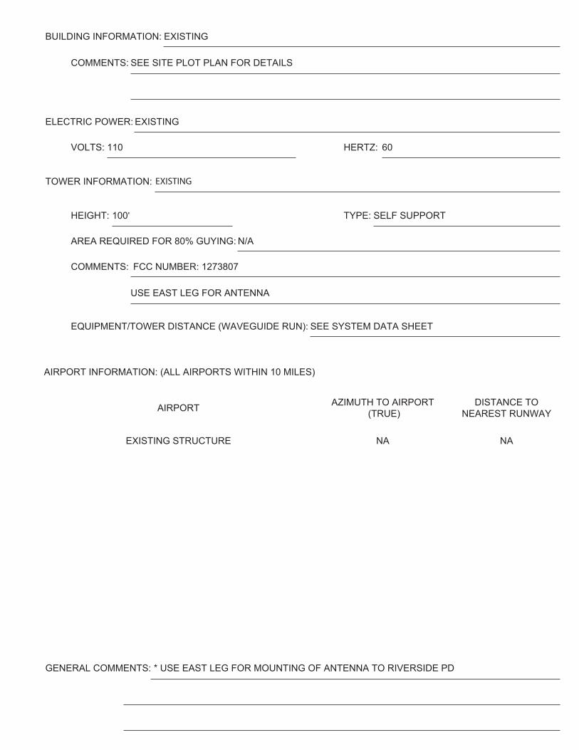
BUILDING INFORMATION: EXISTING
COMMENTS: SEE SITE PLOT PLAN FOR DETAILS
ELECTRIC POWER: EXISTING
VOLTS: 110 HERTZ: 60
TOWER INFORMATION: EXISTING
HEIGHT: 100' TYPE: SELF SUPPORT
AREA REQUIRED FOR 80% GUYING: N/A
COMMENTS: FCC NUMBER: 1273807
USE EAST LEG FOR ANTENNA
EQUIPMENT/TOWER DISTANCE (WAVEGUIDE RUN): SEE SYSTEM DATA SHEET
AIRPORT AZIMUTH TO AIRPORT (TRUE)
DISTANCE TO NEAREST RUNWAY
EXISTING STRUCTURE NA NA
AIRPORT INFORMATION: (ALL AIRPORTS WITHIN 10 MILES)
GENERAL COMMENTS: * USE EAST LEG FOR MOUNTING OF ANTENNA TO RIVERSIDE PD
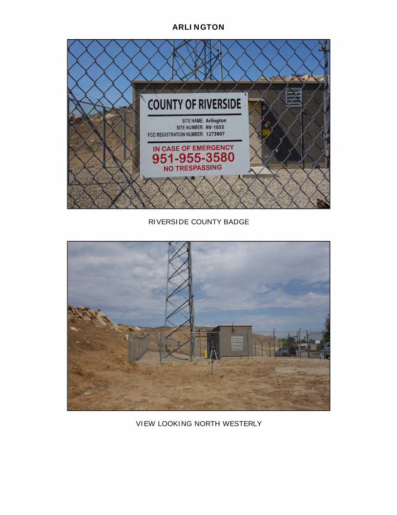
ARLINGTON
RIVERSIDE COUNTY BADGE
VIEW LOOKING NORTH WESTERLY
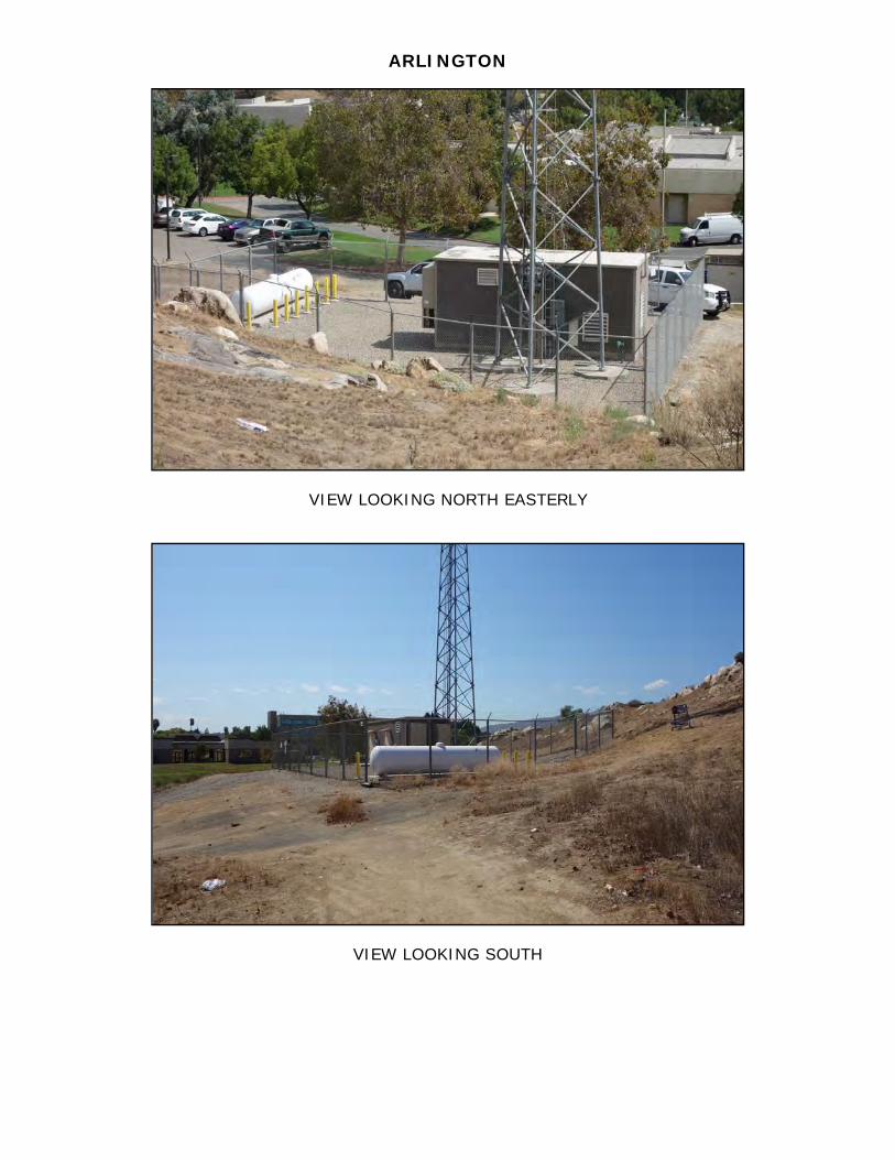
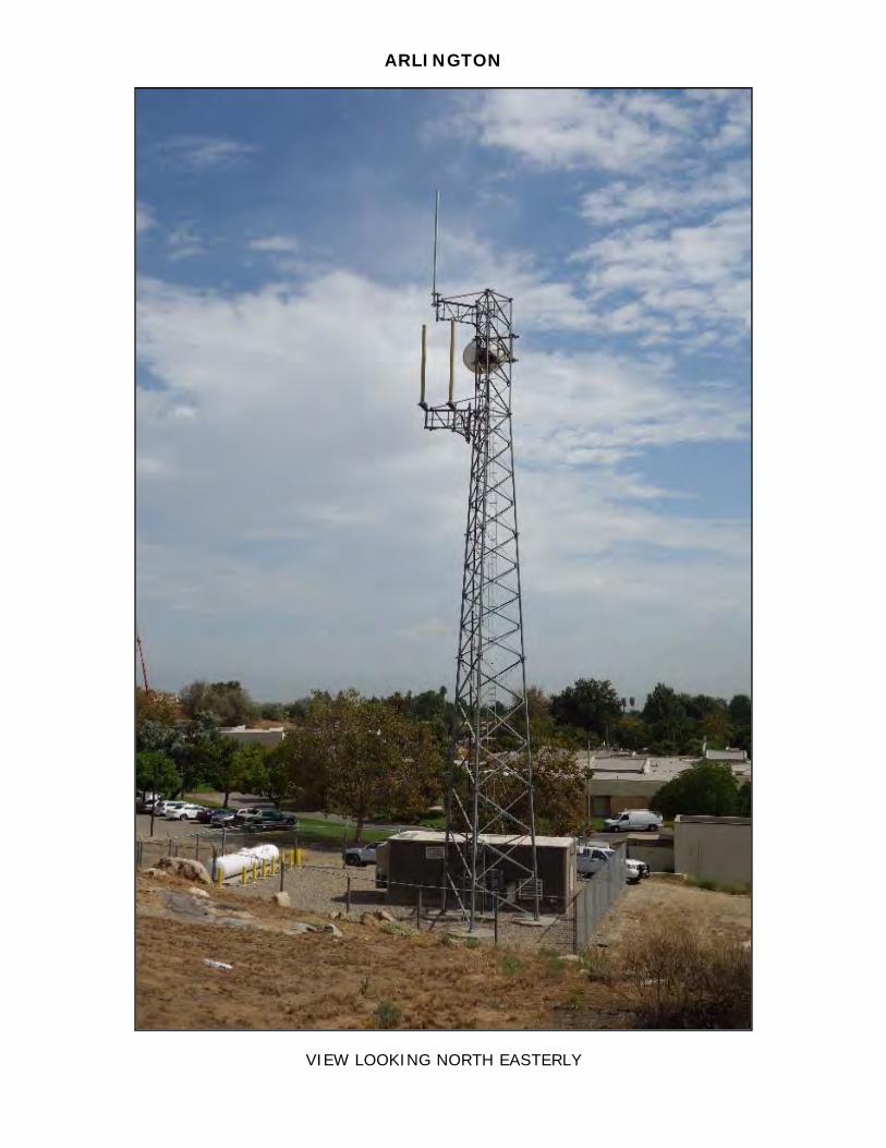
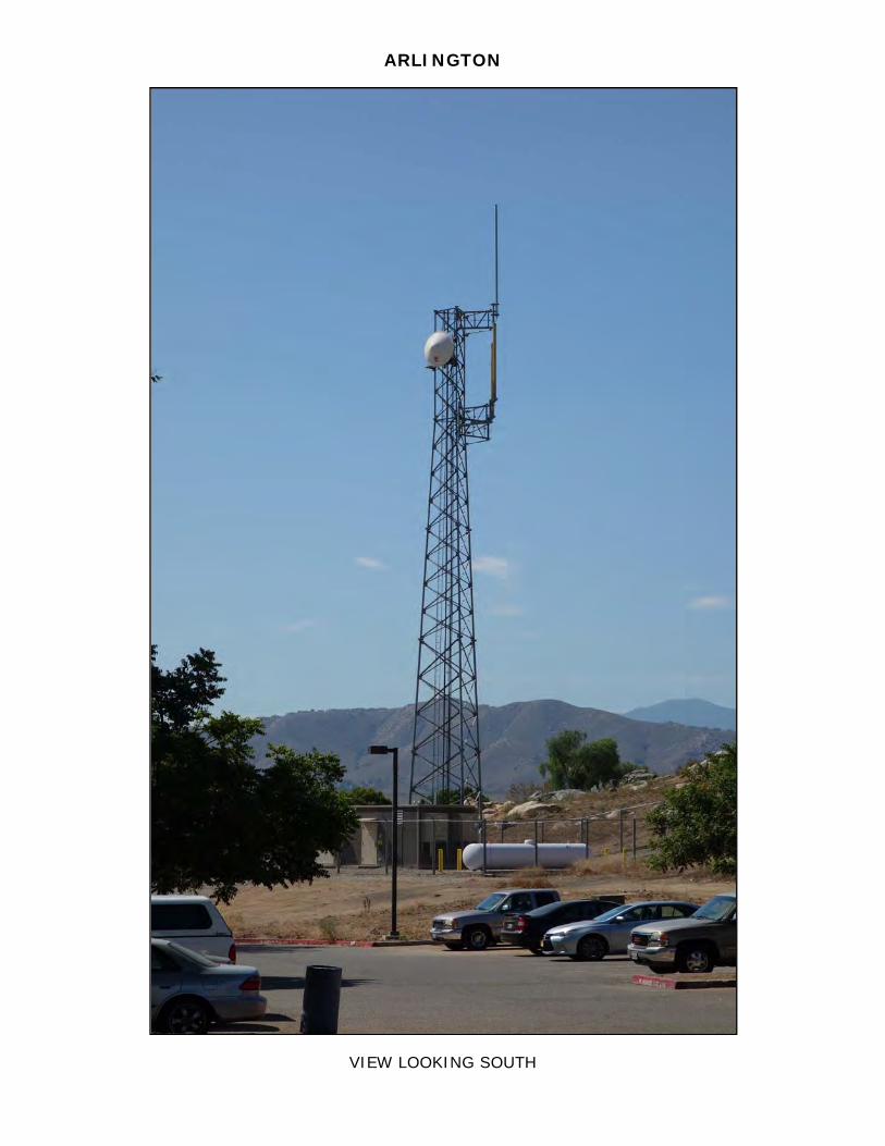
ARLINGTON
VIEW LOOKING NORTH EASTERLY
VIEW LOOKING SOUTH
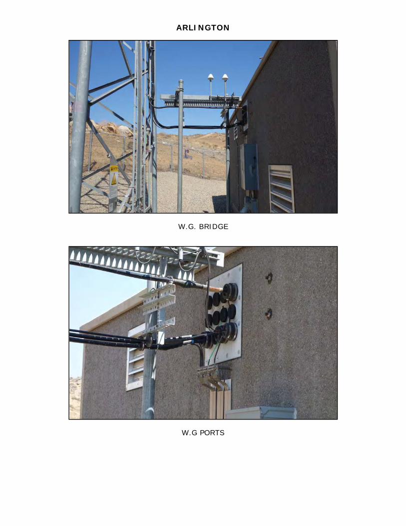
ARLINGTON
W.G. BRIDGE
W.G PORTS
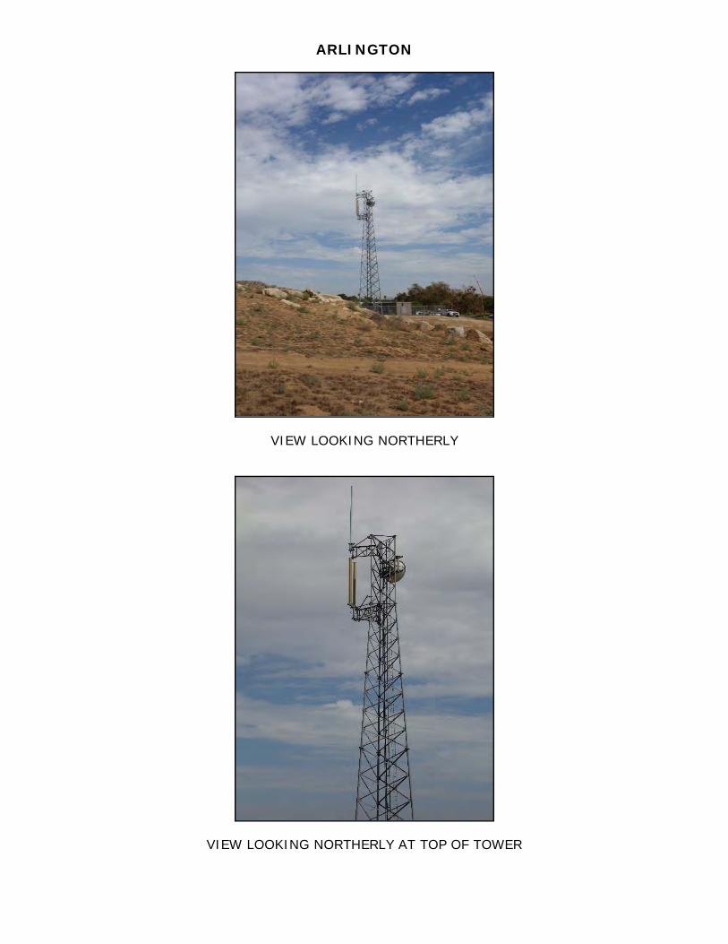
ARLINGTON
VIEW LOOKING NORTHERLY
VIEW LOOKING NORTHERLY AT TOP OF TOWER
ARLINGTON
VIEW LOOKING NORTH EASTERLY
ARLINGTON
VIEW LOOKING SOUTH
RIVERSIDE PD
bley Ave
bley Ave
bley Ave
bley Ave
Bonita A
veB
onita Ave
Bonita A
veB
onita Ave
pley Plupley Pl
pley Plpley Pl
Lively St
Lively St
Lively St
Lively St Pend
leto
n St
Pend
leto
n St
Pend
leto
n St
Pend
leto
n St Hole Ave
Hole AveHole AveHole Ave
Tyler St
Tyler St
Tyler St
Tyler St
Hughes
Hughes
Hughes
Hughes
Galleria at TyleGalleria at TyleGalleria at TyleGalleria at Tyle
loiber Ct
loiber Ct
Kloiber Ct
loiber Ct
e Ct
e Ct
e Ct
e Ct
Stetson Ave
Stetson Ave
Stetson Ave
Stetson Ave
Polk StPolk St
Polk St
Polk St
Magnolia Ave
Magnolia Ave
Magnolia Ave
Magnolia Ave
Allenby St
Allenby St
Allenby St
Allenby StBonneville St
Bonneville St
Bonneville St
Bonneville St
Hemet St
Hemet St
Hemet St
Hemet St
Galleria at T
yler
Galleria at T
yler
Galleria at T
yler
Galleria at T
yler
Nordstrom-Galleria at TyleNordstrom-Galleria at TyleNordstrom-Galleria at TyleNordstrom-Galleria at Tyle
Magnolia Ave
Magnolia Ave
Magnolia Ave
Magnolia Ave
ark Sierra Dr
Park Sierra Dr
Park Sierra Dr
Park Sierra Dr
rcer Ave
rcer Ave
rcer Ave
rcer Ave
Polk StPolk St
Polk St
Polk St
Nye Ave
Nye Ave
Nye Ave
Nye Ave
White O
ak Dr
White O
ak Dr
White O
ak Dr
White O
ak Dr91
Tyler St
Tyler St
Tyler St
Tyler St
Banbury Dr
Banbury Dr
Banbury Dr
Banbury Dr
Diana Ave
Diana Ave
Diana Ave
Diana Ave
91
Diana AveDiana AveDiana AveDiana Ave
Castle ParkCastle ParkCastle ParkCastle Park
91 Erie Dr
Erie Dr
Erie Dr
Erie Dr
tine Pl
ntine Pl
ntine Pl
ntine Pl
Nez Perce T
Nez Perce
Nez Perce T
Nez Perce
Baffin DrBaffin Dr
Baffin DrBaffin DrPortsmouth Ct
Portsmouth Ct
Portsmouth Ct
Portsmouth Ct
Indiana Ave
Indiana Ave
Indiana Ave
Indiana Ave
Riverside PD
CanMap®, DMTI Spatial and the DMTI Spatial logo are trademarks of DMTI Spatial Inc., Markham, Ontario.© Garmin Ltd. or its subsidiaries 2013.© NAVTEQ Maps and NAVTEQ Traffic are trademarks of Nokia. © 2013 Nokia. All rights reserved.
1600 ft1200 ft800 ft400 ft0 ftMNTN
1/1/2010
12.5°
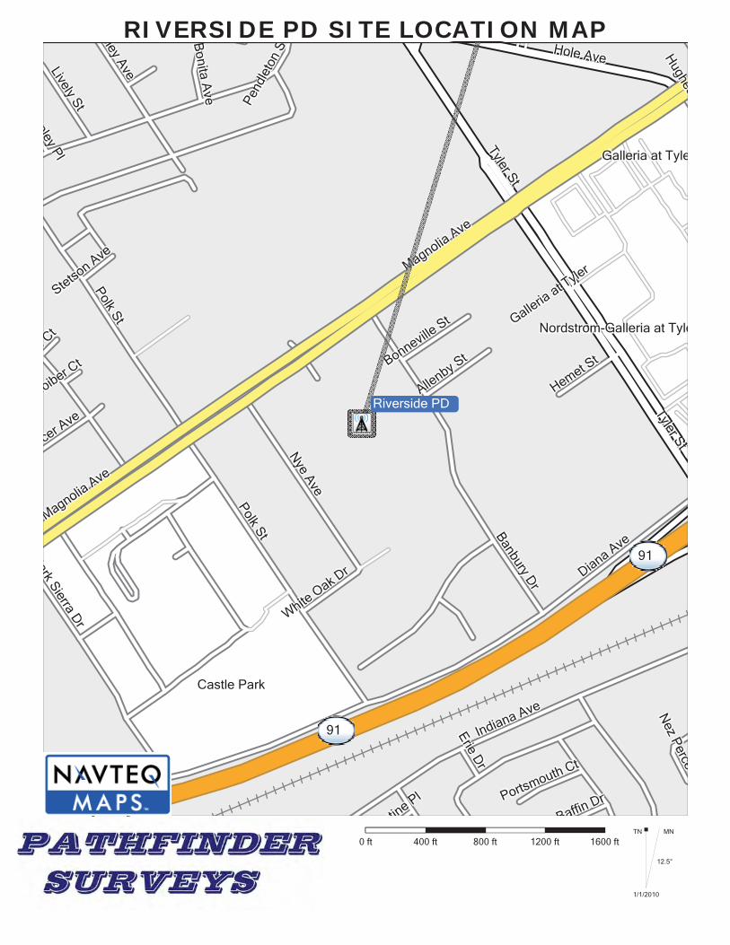
RIVERSIDE PD SITE LOCATION MAP
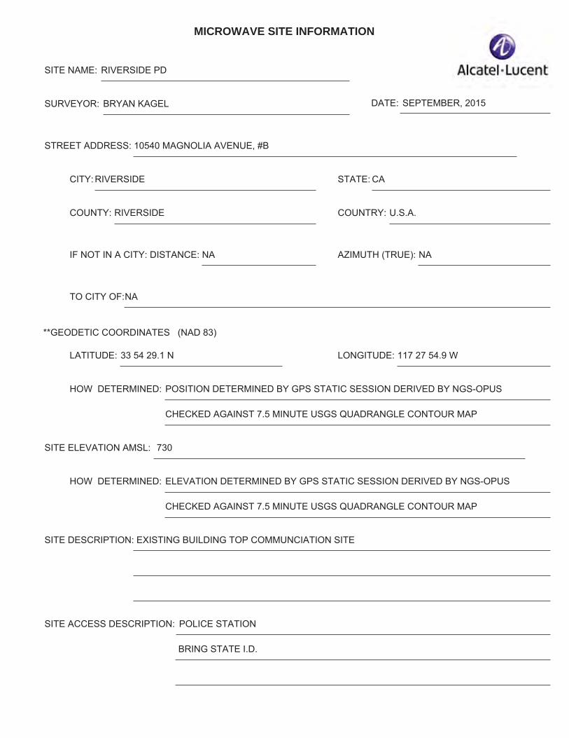
MICROWAVE SITE INFORMATION
SITE NAME: RIVERSIDE PD
SURVEYOR: BRYAN KAGEL DATE: SEPTEMBER, 2015
STREET ADDRESS: 10540 MAGNOLIA AVENUE, #B
CITY: RIVERSIDE
COUNTY: RIVERSIDE COUNTRY: U.S.A.
IF NOT IN A CITY: DISTANCE: NA AZIMUTH (TRUE): NA
TO CITY OF:NA
**GEODETIC COORDINATES (NAD 83)
LATITUDE: 33 54 29.1 N LONGITUDE: 117 27 54.9 W
STATE: CA
HOW DETERMINED: POSITION DETERMINED BY GPS STATIC SESSION DERIVED BY NGS-OPUS
CHECKED AGAINST 7.5 MINUTE USGS QUADRANGLE CONTOUR MAP
SITE ELEVATION AMSL: 730
HOW DETERMINED: ELEVATION DETERMINED BY GPS STATIC SESSION DERIVED BY NGS-OPUS
CHECKED AGAINST 7.5 MINUTE USGS QUADRANGLE CONTOUR MAP
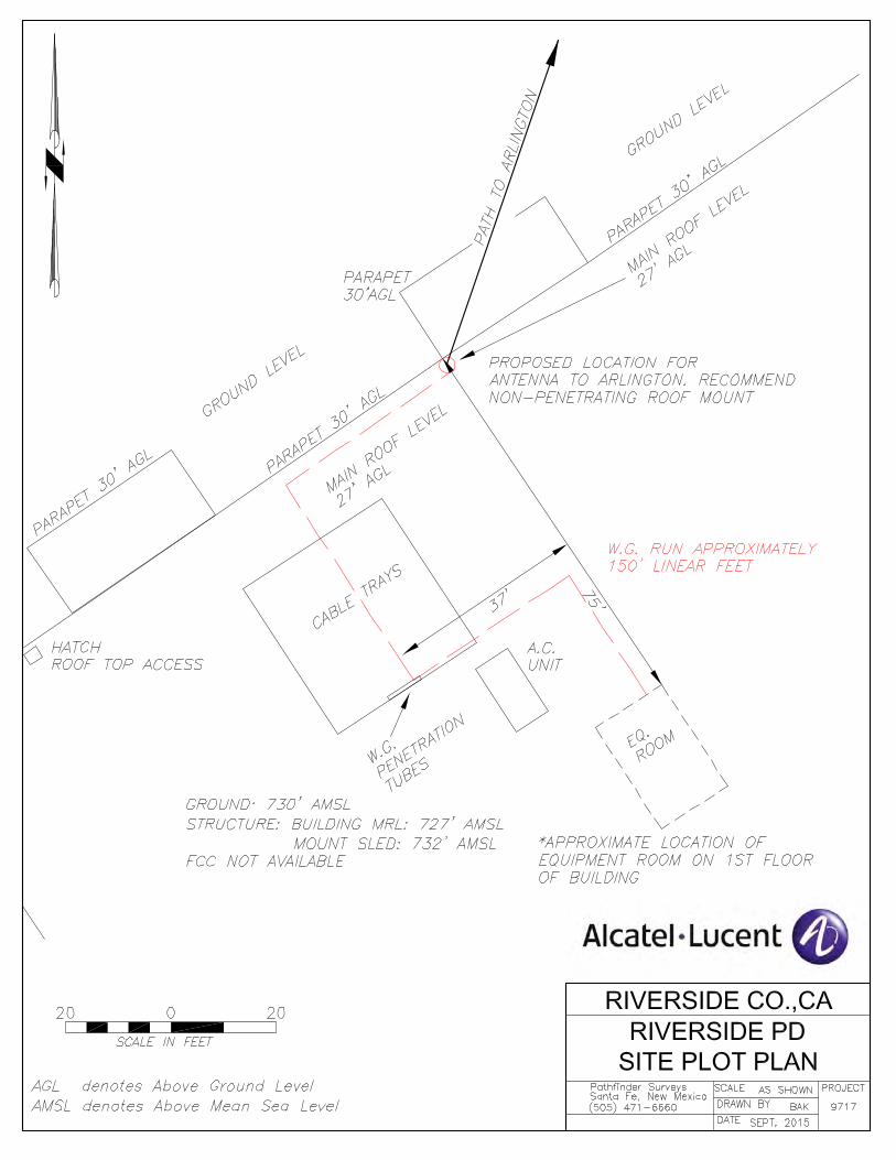
SITE DESCRIPTION: EXISTING BUILDING TOP COMMUNCIATION SITE
SITE ACCESS DESCRIPTION: POLICE STATION
BRING STATE I.D.
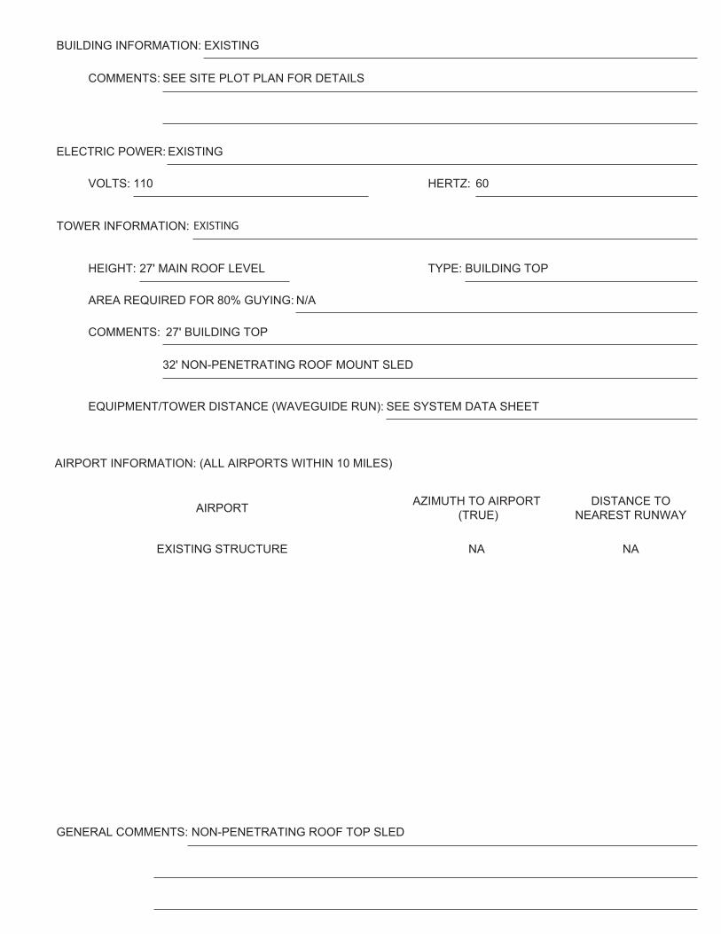
BUILDING INFORMATION: EXISTING
COMMENTS: SEE SITE PLOT PLAN FOR DETAILS
ELECTRIC POWER: EXISTING
VOLTS: 110 HERTZ: 60
TOWER INFORMATION: EXISTING
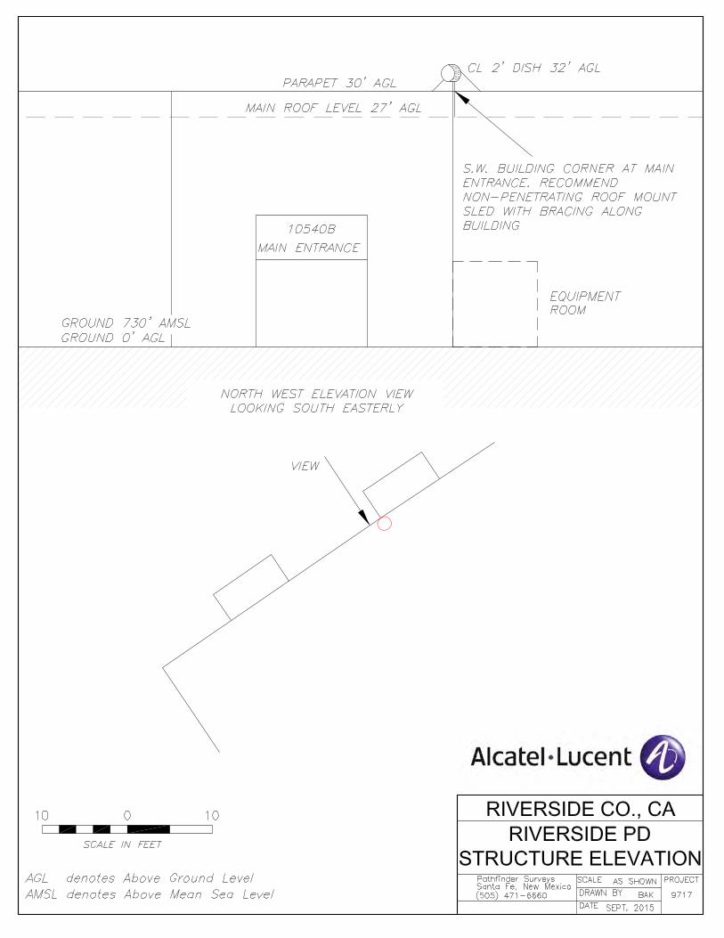
HEIGHT: 27' MAIN ROOF LEVEL TYPE: BUILDING TOP
AREA REQUIRED FOR 80% GUYING: N/A
COMMENTS: 27' BUILDING TOP
32' NON-PENETRATING ROOF MOUNT SLED
EQUIPMENT/TOWER DISTANCE (WAVEGUIDE RUN): SEE SYSTEM DATA SHEET
AIRPORT AZIMUTH TO AIRPORT (TRUE)
DISTANCE TO NEAREST RUNWAY
EXISTING STRUCTURE NA NA
AIRPORT INFORMATION: (ALL AIRPORTS WITHIN 10 MILES)
GENERAL COMMENTS: NON-PENETRATING ROOF TOP SLED
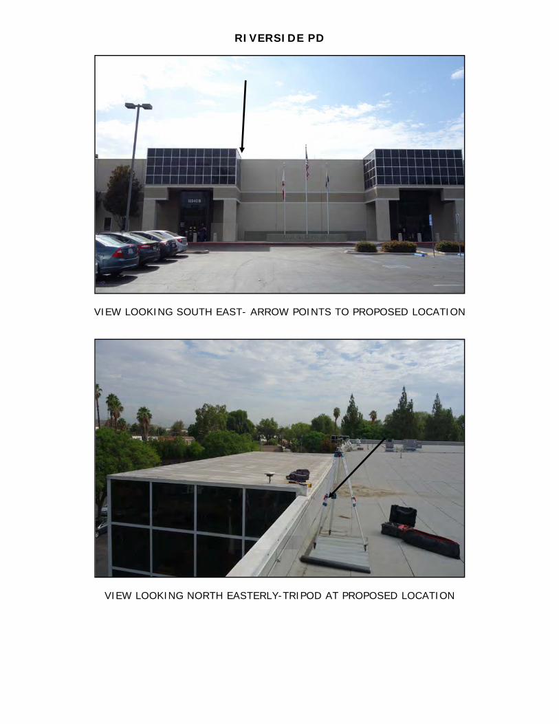
RIVERSIDE PD
VIEW LOOKING SOUTH EAST- ARROW POINTS TO PROPOSED LOCATION
VIEW LOOKING NORTH EASTERLY-TRIPOD AT PROPOSED LOCATION
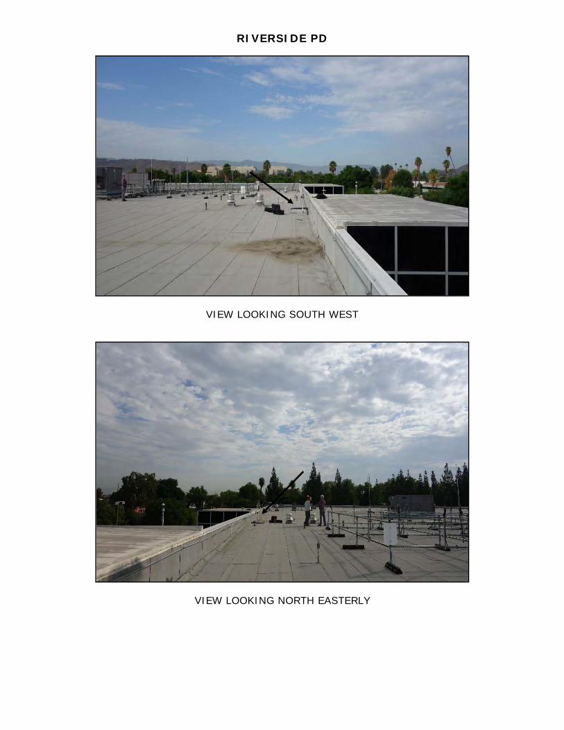
RIVERSIDE PD
VIEW LOOKING SOUTH WEST
VIEW LOOKING NORTH EASTERLY
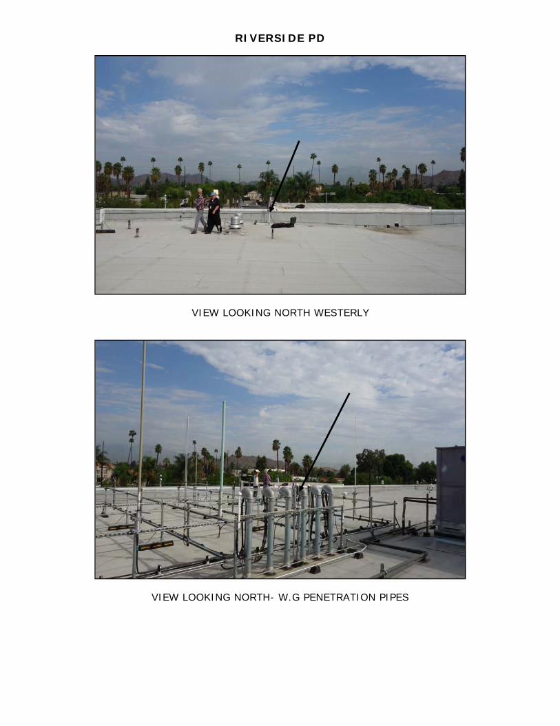
RIVERSIDE PD
VIEW LOOKING NORTH WESTERLY
VIEW LOOKING NORTH- W.G PENETRATION PIPES
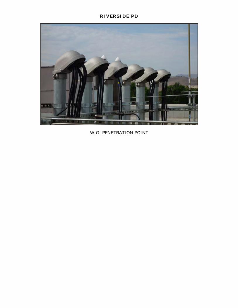
RIVERSIDE PD
W.G. PENETRATION POINT
PATH
DESCRIPTION(S)
RIVERSIDE PD
TO
ARLINGTON
PATH DESCRIPTION
GENERAL DESCRIPTION OF TERRAIN FEATURES:
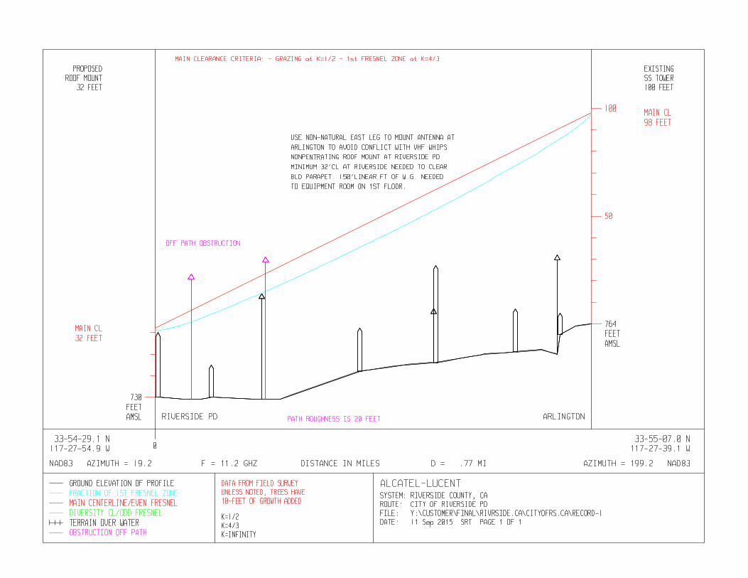
This path passes from an existing roof top mount at Riverside PD to an existing self -support
tower at Arlington. Terrain traverses through urban environment over relatively flat profile with
no near field obstructions. Recommend using east leg of Arlingto n self-support tower to
prevent relocation of existing whip antennas.
DETAILED DESCRIPTION OF TERRAIN FEATURES AND CRITICAL POINTS:
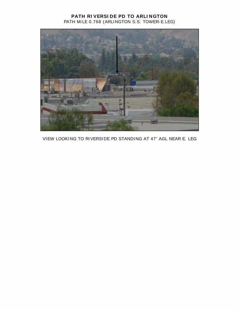
PATH RIVERSIDE PD TO ARLINGTON
MILEAGE DESCRIPTION
0.00 Existing building top at Riverside PD.
0.00-0.768 Relatively flat profile over urban terrain.
.005 Building parapet.
.063 58’ agl Palm tree. Palm is 19’ west of path azimuth.
.187 Deciduous tree which is 39’ + 10’ future growth. Tree is controlling feature of path.
.494 45’ agl Wood utility pole. Pole is 3’ west of path azimuth.
.708 Deciduous tree at 36’ + 10’ future growth.
.768 Existing self-support tower at Arlington.
*Recommend using east leg at Arlington tower to avoid relocation of whip antennas on west leg.
Terrain Data - RIVERSIDE PD-ARLINGTON.pl4 Fri, Sep 11 2015
RIVERSIDE PD ARLINGTON
State CA CALatitude 33 54 29.10 N 33 55 07.00 N
Longitude 117 27 54.90 W 117 27 39.10 WTrue azimuth (°) 019 09 53.03 199 10 01.85
Calculated Distance (mi) 0.768Profile Distance (mi) 0.768
Datum North American 1983UTM zone 11N 11N
Easting (km) 456.989 457.400Northing (km) 3752.062 3753.227Elevation (ft) 730.00 764.00
Distance (mi) Elevation (ft) Ground Structure (ft)
0.000 730.00 AG0.005 730.00 AG 30.0 ft Building - BLD PARAPET0.050 729.00 AG0.063 729.00 AG 58.0 ft Tree - Off Path Structure0.080 729.00 AG0.099 730.00 AG 15.0 ft Building - COMMERCIAL BLD0.187 729.00 AG 49.0 ft Tree - 39+10FG/DECIDUOUS0.194 729.00 AG 66.0 ft Tree - Off Path Structure0.220 729.00 AG0.360 742.00 AG 20.0 ft Building - COMMERCIAL BLD0.440 745.00 AG0.490 746.00 AG 25.0 ft Tree0.494 746.00 AG 45.0 ft Building - WOOD UT POLE-3' WEST0.580 750.00 AG0.634 751.00 AG 20.0 ft Building - WAREHOUSE BLD0.680 752.00 AG0.708 750.00 AG 46.0 ft Tree - 36+10FG/DECIDUOUS0.713 759.00 AG 10.0 ft Building - ROCK OUT CROP/MONOLITH0.740 763.00 AG0.768 764.00 AG
Ground Elevations - AMSL, Structure & Antenna Heights - AGLGround TypePG - Poor, AG - Average, GG - Good, FW - Fresh Water, SW - Salt Water
Off Path Tree at 0.063 mi - PALM/19' W.PATHDistance Off Path (ft) 19.0Ground Elevation (ft) 729.0Structure Height (ft) 58.0
Off Path Tree at 0.194 mi - OAK TREE/20' EAST PATHDistance Off Path (ft) 20.0Ground Elevation (ft) 732.0Structure Height (ft) 66.0
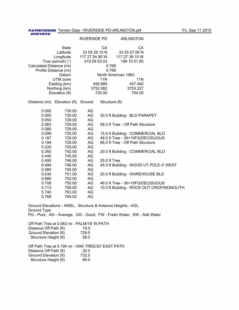
PATH RIVERSIDE PD TO ARLINGTON PATH MILE 0.00 (RIVERSIDE PD –BUILDING TOP)
VIEW LOOKING TO ARLINGTON STANDING ON MAIN ROOF LEVEL AT
PROPOSED LOCATION
VIEW LOOKING TO ARLINGTON STANDING ON MAIN ROOF LEVEL AT
PROPOSED LOCATION
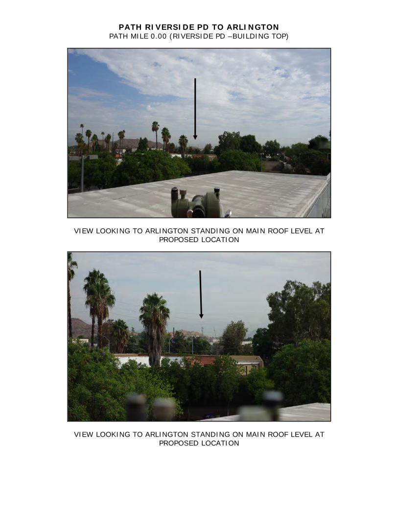
PATH RIVERSIDE PD TO ARLINGTON PATH MILE 0.00 (RIVERSIDE PD –BUILDING TOP)
VIEW LOOKING TO ARLINGTON STANDING ON MAIN ROOF LEVEL AT
PROPOSED LOCATION
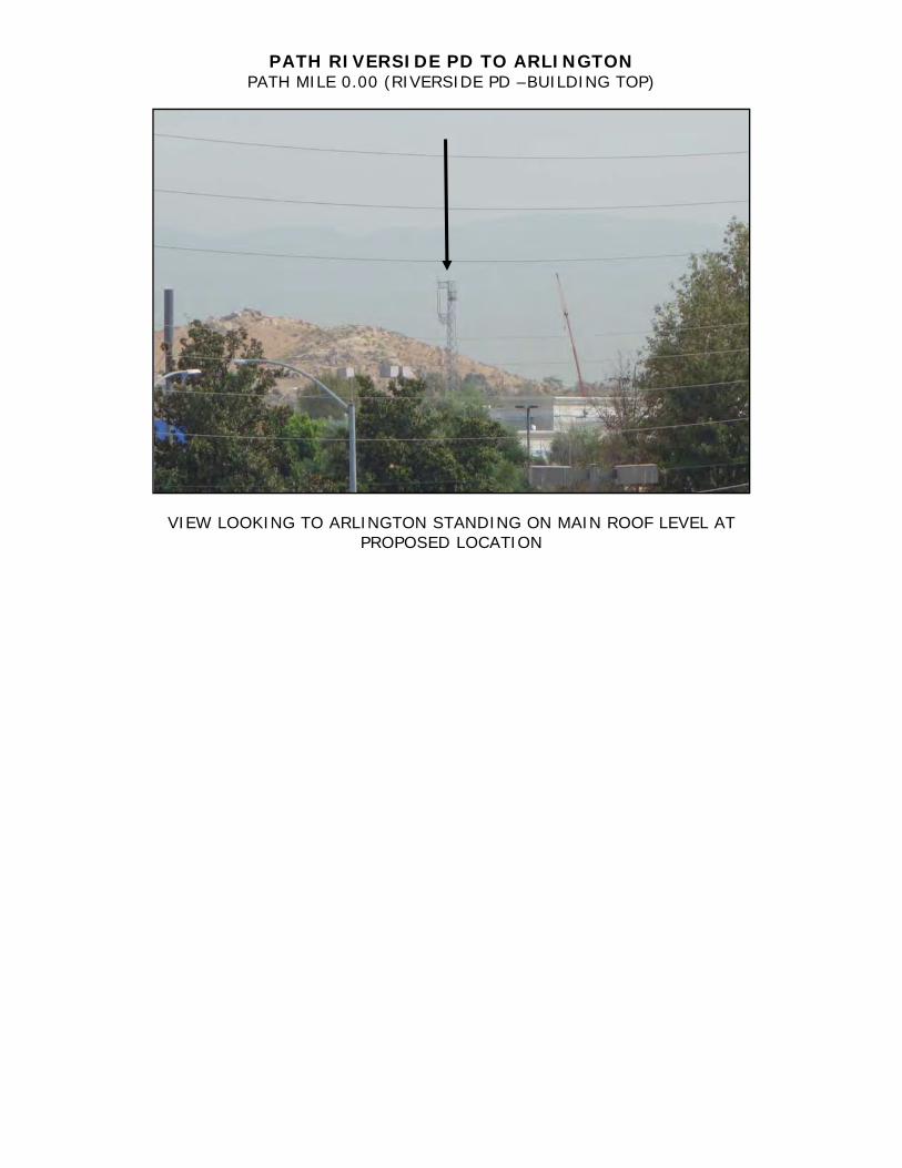
PATH RIVERSIDE PD TO ARLINGTON PATH MILE 0.768 (ARLINGTON S.S. TOWER-E.LEG)
VIEW LOOKING TO RIVERSIDE PD STANDING AT 47’ AGL NEAR E. LEG
VIEW LOOKING TO RIVERSIDE PD STANDING AT 47’ AGL NEAR E. LEG
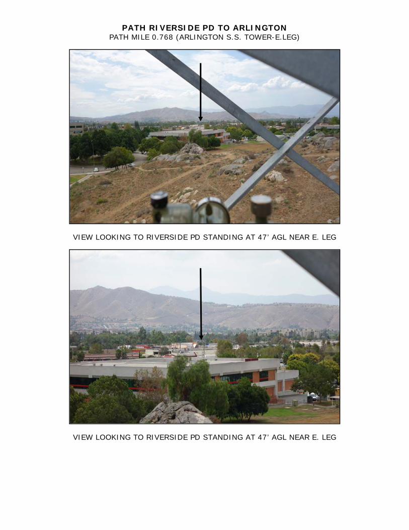
PATH RIVERSIDE PD TO ARLINGTON PATH MILE 0.768 (ARLINGTON S.S. TOWER-E.LEG)
VIEW LOOKING TO RIVERSIDE PD STANDING AT 47’ AGL NEAR E. LEG

PATH
DESIGN
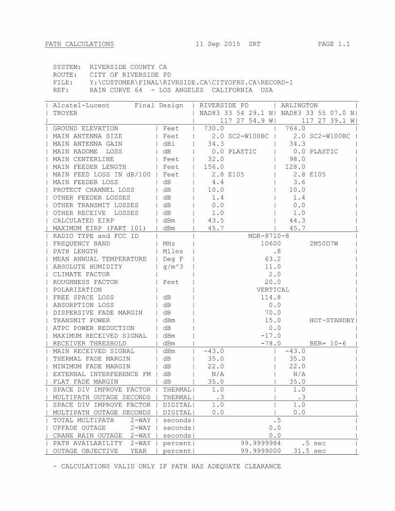
PATH CALCULATIONS 11 Sep 2015 SRT PAGE 1.1
SYSTEM: RIVERSIDE COUNTY CA
ROUTE: CITY OF RIVERSIDE PD
FILE: Y:\CUSTOMER\FINAL\RIVRSIDE.CA\CITYOFRS.CA\RECORD-1
REF: RAIN CURVE 64 - LOS ANGELES CALIFORNIA USA
_____________________________________________________________________________
| Alcatel-Lucent Final Design | RIVERSIDE PD | ARLINGTON |
| TROYER | NAD83 33 54 29.1 N| NAD83 33 55 07.0 N|
| | 117 27 54.9 W| 117 27 39.1 W|
| GROUND ELEVATION | Feet | 730.0 | 764.0 |
| MAIN ANTENNA SIZE | Feet | 2.0 SC2-W100BC | 2.0 SC2-W100BC |
| MAIN ANTENNA GAIN | dBi | 34.3 | 34.3 |
| MAIN RADOME LOSS | dB | 0.0 PLASTIC | 0.0 PLASTIC |
| MAIN CENTERLINE | Feet | 32.0 | 98.0 |
| MAIN FEEDER LENGTH | Feet | 156.0 | 128.0 |
| MAIN FEED LOSS IN dB/100 | Feet | 2.8 E105 | 2.8 E105 |
| MAIN FEEDER LOSS | dB | 4.4 | 3.6 |
| PROTECT CHANNEL LOSS | dB | 10.0 | 10.0 |
| OTHER FEEDER LOSSES | dB | 1.4 | 1.4 |
| OTHER TRANSMIT LOSSES | dB | 0.0 | 0.0 |
| OTHER RECEIVE LOSSES | dB | 1.0 | 1.0 |
| CALCULATED EIRP | dBm | 43.5 | 44.3 |
| MAXIMUM EIRP (PART 101) | dBm | 45.7 | 45.7 |
| RADIO TYPE and FCC ID | | MDR-8710-8 |
| FREQUENCY BAND | MHz | 10600 2M50D7W |
| PATH LENGTH | Miles | .8 |
| MEAN ANNUAL TEMPERATURE | Deg F | 63.2 |
| ABSOLUTE HUMIDITY | g/m^3 | 11.0 |
| CLIMATE FACTOR | | 2.0 |
| ROUGHNESS FACTOR | Feet | 20.0 |
| POLARIZATION | | VERTICAL |
| FREE SPACE LOSS | dB | 114.8 |
| ABSORPTION LOSS | dB | 0.0 |
| DISPERSIVE FADE MARGIN | dB | 70.0 |
| TRANSMIT POWER | dBm | 15.0 HOT-STANDBY|
| ATPC POWER REDUCTION | dB | 0.0 |
| MAXIMUM RECEIVED SIGNAL | dBm | -17.0 |
| RECEIVER THRESHOLD | dBm | -78.0 BER= 10-6 |
| MAIN RECEIVED SIGNAL | dBm | -43.0 | -43.0 |
| THERMAL FADE MARGIN | dB | 35.0 | 35.0 |
| MINIMUM FADE MARGIN | dB | 22.0 | 22.0 |
| EXTERNAL INTERFERENCE FM | dB | N/A | N/A |
| FLAT FADE MARGIN | dB | 35.0 | 35.0 |
| SPACE DIV IMPROVE FACTOR | THERMAL| 1.0 | 1.0 |
| MULTIPATH OUTAGE SECONDS | THERMAL| .3 | .3 |
| SPACE DIV IMPROVE FACTOR | DIGITAL| 1.0 | 1.0 |
| MULTIPATH OUTAGE SECONDS | DIGITAL| 0.0 | 0.0 |
| TOTAL MULTIPATH 2-WAY | seconds| .5 |
| UPFADE OUTAGE 2-WAY | seconds| 0.0 |
| CRANE RAIN OUTAGE 2-WAY | seconds| 0.0 |
| PATH AVAILABILITY 2-WAY | percent| 99.9999984 .5 sec |
| OUTAGE OBJECTIVE YEAR | percent| 99.9999000 31.5 sec |
- CALCULATIONS VALID ONLY IF PATH HAS ADEQUATE CLEARANCE

WARRANTY
OF
WORK
Page 1 of 3 Jan 2012 Alcatel-Lucent, 601 Data Drive, Plano, Texas 75075
MICROWAVE PATH ENGINEERING WARRANTY
FEASIBILITY STUDIES
Alcatel-Lucent provides feasibility studies of microwave radio paths in support of bidding efforts or when purchased by the Customer. Feasibility studies are performed using information provided by or on behalf of the Customer. Results of the feasibility study are provided to the Customer and may include (i) a system map, (ii) a path profile, (iii) path performance calculations, and (iv) a technical report.
Feasibility studies are preliminary in nature and are not intended to represent a final design. Therefore no representations, warranty or guarantee is implied or provided. Customer agrees to assume all risks associated with installing any equipment based on spiderweb maps, preliminary network and system maps, preliminary path profiles (including antenna size and location), path calculations (estimated performance), Google Earth, and topology studies normally presented with a feasibility study.
PATH SURVEYS (DETAILED SURVEY WITH REPORT)
Alcatel-Lucent offers detailed path surveying services to determine or verify site coordinates, site access, location, ground elevation, on-path obstruction location and height, tower information, proposed antenna centerline information, and other parameters required to engineer and implement a microwave radio link. The present and anticipated future effect of observable on-path obstructions, such as vegetation and buildings, are also evaluated and incorporated into the path design where applicable. Where appropriate, roof top access may be utilized in the survey effort. Existing towers are not climbed as a part of this activity.
The results of the path survey are documented and presented in a formal survey report or technical report, as required, to the Customer. Some items performed and included in a formal survey report may include: site location map, site topographic map, access information, site plot plans, existing tower elevation profile, site photographs, site and path observations, path terrain feature descriptions, critical point data, engineering notes, path profiles, and proposed performance calculations.
For detailed Path Surveys, Alcatel-Lucent warrants that geodetic coordinates are accurate to within +/- 1- second of latitude, +/- 1-second of longitude, ground elevations are accurate to within +/- 1 meter, and that heights of identified on-path obstructions at critical points are accurate to within 5-feet. Alcatel- Lucent warrants only the actual paths surveyed.
LINE OF SIGHT SURVEYS (LOS - CLEARANCE VERIFICATION)
Alcatel-Lucent offers a simplified microwave path survey service (from that described above) to determine “line of sight” (LOS) and adequate clearance conditions exist for a planned microwave link. This survey approach is best suited for urban and suburban environments. It can include driving the path as done in a traditional path survey, flashing the path, mirrors, or binoculars methodology. The line of sight survey may also ascertain site coordinates, site access and location, ground elevation, on-path obstruction location and height, tower information, proposed antenna centerline information, and other basic parameters required to evaluate and design a microwave radio link. The present and anticipated future effect of observable on-path obstructions, such as existing vegetation and existing buildings, are evaluated and incorporated into the path design where applicable and appropriate. Where appropriate,
Page 2 of 3 Jan 2012 Alcatel-Lucent, 601 Data Drive, Plano, Texas 75075
roof top access may be utilized in the survey effort. Existing towers are not climbed as a part of this activity.
For line of sight (LOS) surveys, Alcatel-Lucent warrants that geodetic coordinates are accurate to within +/- 1-second of latitude, +/- 1-second of longitude, and ground elevations are accurate to within +/- 1 meter. Alcatel-Lucent warrants only the actual paths surveyed.
PATH DESIGN
Alcatel-Lucent offers path design services. Path design services are based on formal field survey data gathered by Alcatel-Lucent path surveyors and is warranted. Path designs include profiling a path to determine antenna centerline requirements, and path calculations to determine the antenna and radio types necessary to meet the Customer’s microwave link performance and availability objectives. Recommended antenna centerlines are determined for a range of K-factors expected to occur during an average year and by the Fresnel zone clearance criteria stipulated by Bell Laboratories. For areas where poor propagation conditions are known to exist, paths are assessed for susceptibility to obstruction fading outages using the Bell Laboratories Obstruction Fading (OBSFAD) model. Additionally, paths are analyzed for ground-based reflections.
Microwave link availability (path availability) is evaluated using current North American industry accepted models for predicting outage times and diversity improvement factors associated with normal atmospheric multipath fading (flat and dispersive), rain fading, and obstruction fading. Every effort is made by Alcatel- Lucent to anticipate the probable occurrence of abnormal propagation conditions based on historical documentation, experience, geographical location, and field survey data.
The final path design documentation will include one or more of the following, depending on the services purchased by the Customer: (i) a system map, (ii) a final path profile, (iii) final path performance calculations, and (iv) a technical report.
If a radio path using Alcatel-Lucent equipment is installed based on Alcatel-Lucent’s recommended path design, then Alcatel-Lucent warrants the radio path calculations shall conform to the Customer’s availability objective for normal atmospheric multipath fading. Alcatel-Lucent will not be held responsible for excessive outages or degraded performance due to abnormal fading conditions. Abnormal fading conditions include, but are not limited to:
Formation of extreme radio refractivity gradients associated with:
Exceptionally large temperature inversions Abnormal temperature/humidity layers Fog formation Signal trapping caused by surface or atmospheric ducting
Reflections from unusual or unidentifiable on-path or off-path terrain features, physical structures, or atmospheric layers.
Rain fading due to rainfall rates that are in excess of the published rates or charts used to
predict rain induced outages. If Alcatel-Lucent suspects that abnormal propagation conditions are the cause of degraded system performance, Alcatel-Lucent will assist the Customer in verifying the conditions leading to the degraded system performance. After the problem has been identified, Alcatel-Lucent will support the Customer in identifying possible solutions to the problem and assess the incremental improvement expected from corrective actions. Any Implementation of corrective action to remedy this type of problem shall be the sole responsibility of the Customer.
Page 3 of 3 Jan 2012 Alcatel-Lucent, 601 Data Drive, Plano, Texas 75075
FREQUENCY PLANNING
Alcatel-Lucent offers frequency planning services including frequency selection, prior coordination process, interference case resolution, and FCC license application documentation preparation and submittal. Alcatel-Lucent warrants that the interference studies will be conducted using industry-accepted North American methods, hardware, software and algorithms; and that the frequency database will be maintained as accurately as possible at the time of the study. Alcatel-Lucent will not be held responsible for interference cases that arise due to errors or omissions in the database. Upon completion of the frequency planning services, some or all of the following documentation is provided to the Customer:
Prior Coordination Notice
Frequency Coordination Data Sheet
Supplemental Showing pursuant to FCC Rules Part 101.103(d)
Completed FCC Form 601 License Application and Preparation
In the event harmful frequency interference is detected during the implementation of a microwave line in which Alcatel-Lucent provided the frequency planning services, Alcatel-Lucent’s total liability is limited to selection of an alternate frequency or frequencies. Should harmful interference occur after the microwave link is deemed operational and accepted, corrective action is the sole responsibility of the Customer.
WARRANTY
Alcatel-Lucent warrants its path surveys and path designs to be substantially free of engineering defects and errors for a period of 12 months from the date of delivery of the study to the Customer. Alcatel- Lucent warrants its line of sight surveys to be substantially free of engineering defects and errors for a period of 6 months from the date of delivery of the study to the Customer. Alcatel-Lucent warrants its frequency planning and Form 601 License Application preparation to be substantially free of engineering defects and errors for a period of 6 months from the date the path was prior coordinated. Except as further limited above, in the event of a proven breach of warranty, the Customer’s sole remedy under this warranty shall be that Alcatel-Lucent will provide the incremental labor and material beyond what would have been required during initial installation to correct for the particular error in the path survey or path design. In no case shall Alcatel-Lucent be held liable for any indirect damages including but not limited to incidental, consequential or loss of capital, data, revenue or profit. In the event that such error is not solely and directly related to Alcatel-Lucent’s path engineering efforts, expenses for such labor and material shall be borne by the Customer.