Embed Size (px)
Citation preview
Microwave Power Combiners
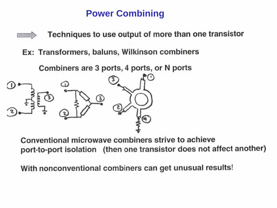
Power Combining
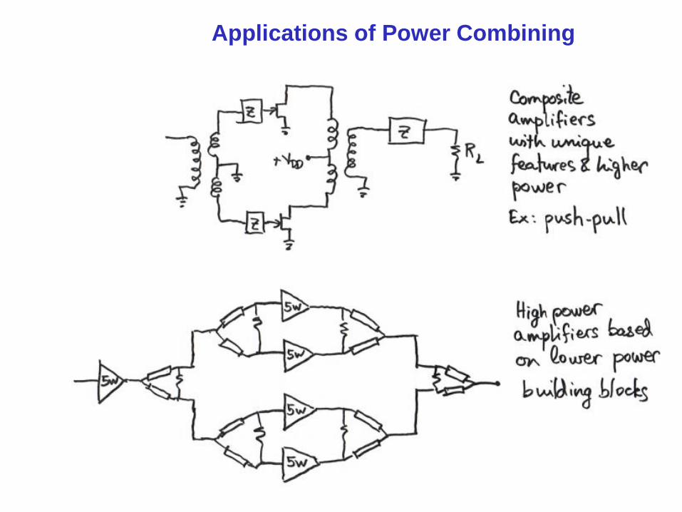
Applications of Power Combining
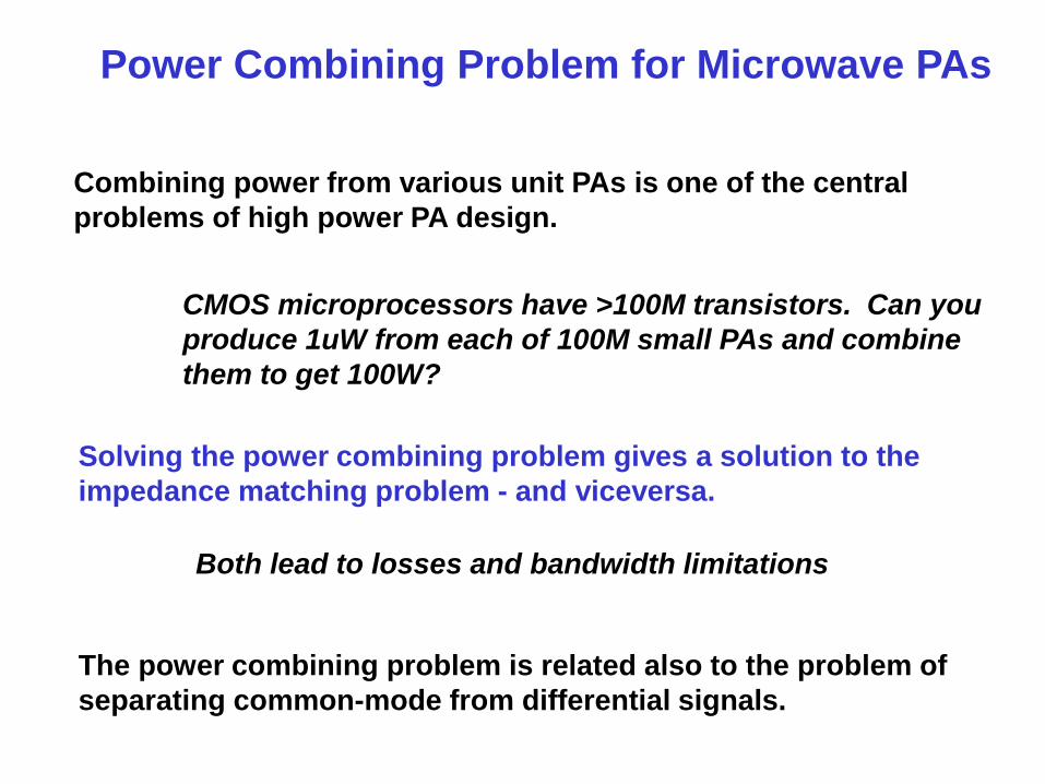
Power Combining Problem for Microwave PAs
Combining power from various unit PAs is one of the central
problems of high power PA design.
CMOS microprocessors have >100M transistors. Can you
produce 1uW from each of 100M small PAs and combine
them to get 100W?
Solving the power combining problem gives a solution to the
impedance matching problem - and viceversa.
The power combining problem is related also to the problem of
separating common-mode from differential signals.
Both lead to losses and bandwidth limitations
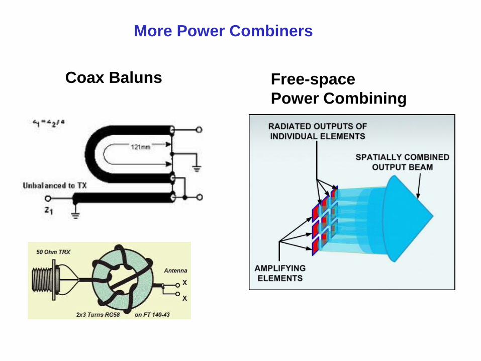
Coax Baluns Free-space
Power Combining
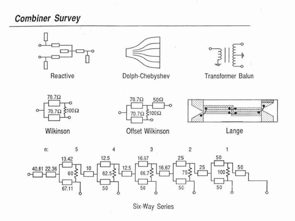
More Power Combiners
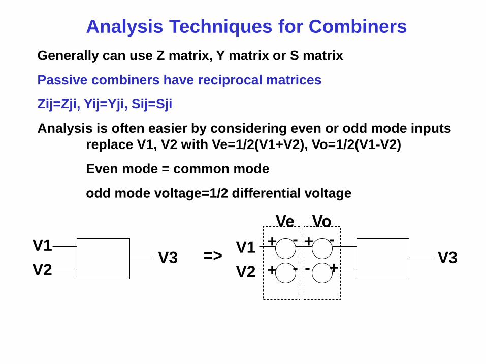
Analysis Techniques for Combiners
Generally can use Z matrix, Y matrix or S matrix
Passive combiners have reciprocal matrices
Zij=Zji, Yij=Yji, Sij=Sji
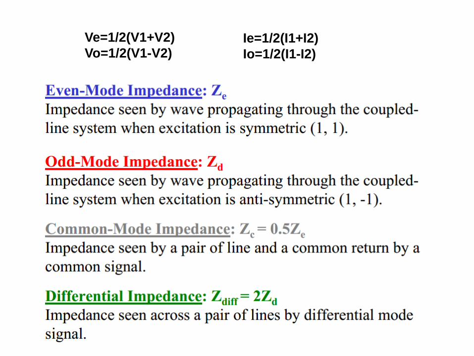
Analysis is often easier by considering even or odd mode inputs
replace V1, V2 with Ve=1/2(V1+V2), Vo=1/2(V1-V2)
Even mode = common mode
odd mode voltage=1/2 differential voltage
V1
V2 V3 =>
V1
V2 V3
Vo Ve
+ -
+ - - +
+ -
+
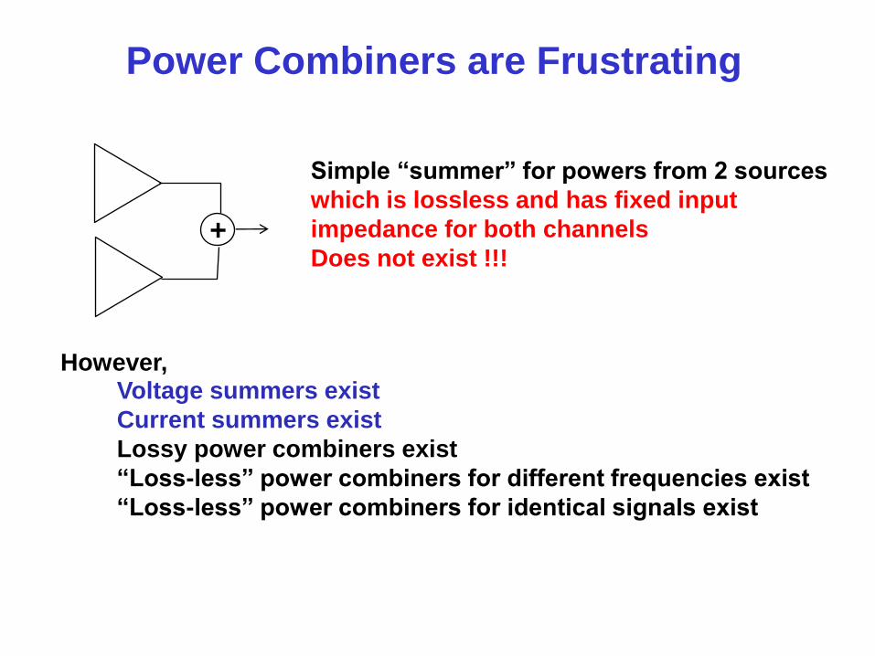
Simple “summer” for powers from 2 sources
which is lossless and has fixed input
impedance for both channels
Does not exist !!!
Voltage summers exist
Current summers exist
Lossy power combiners exist
“Loss-less” power combiners for different frequencies exist
“Loss-less” power combiners for identical signals exist
However,
Power Combiners are Frustrating
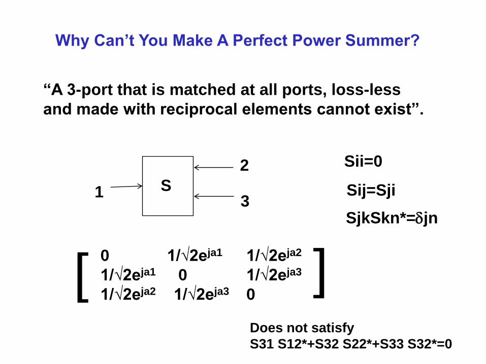
Why Can’t You Make A Perfect Power Summer?
“A 3-port that is matched at all ports, loss-less
and made with reciprocal elements cannot exist”.
1
2
3 S
0 1/√2eja1 1/√2eja2
1/√2eja1 0 1/√2eja3
1/√2eja2 1/√2eja3 0
Sij=Sji
Sii=0
SjkSkn*=djn
] Does not satisfy
S31 S12*+S32 S22*+S33 S32*=0
]
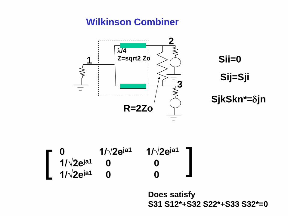
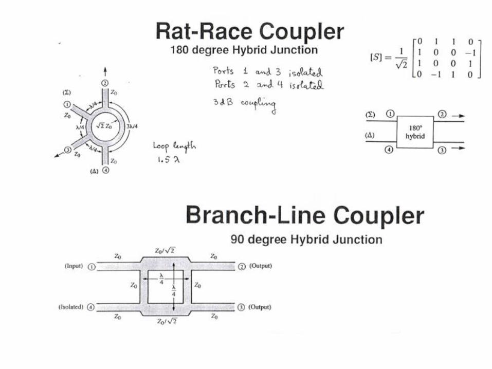
Wilkinson Combiner
0 1/√2eja1 1/√2eja1
1/√2eja1 0 0
1/√2eja1 0 0
Sij=Sji
Sii=0
SjkSkn*=djn
] Does satisfy
S31 S12*+S32 S22*+S33 S32*=0
] 2
3
1 l/4
Z=sqrt2 Zo
R=2Zo
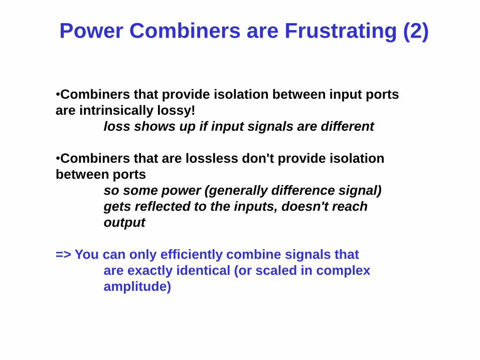
Power Combiners are Frustrating (2)
•Combiners that provide isolation between input ports
are intrinsically lossy!
loss shows up if input signals are different
•Combiners that are lossless don't provide isolation
between ports
so some power (generally difference signal)
gets reflected to the inputs, doesn't reach
output
=> You can only efficiently combine signals that
are exactly identical (or scaled in complex
amplitude)
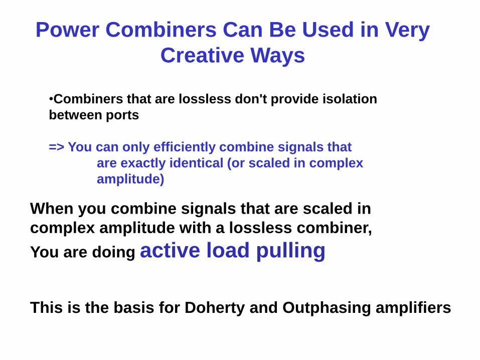
Power Combiners Can Be Used in Very
Creative Ways
•Combiners that are lossless don't provide isolation
between ports
=> You can only efficiently combine signals that
are exactly identical (or scaled in complex
amplitude)
When you combine signals that are scaled in
complex amplitude with a lossless combiner,
You are doing active load pulling
This is the basis for Doherty and Outphasing amplifiers
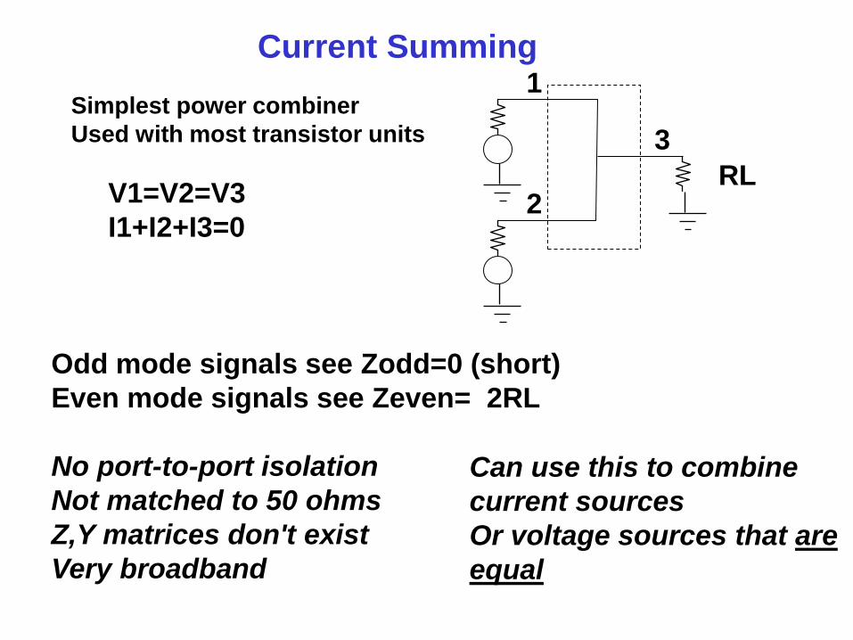
Current Summing
Simplest power combiner
Used with most transistor units
1
2
3
V1=V2=V3
I1+I2+I3=0
Odd mode signals see Zodd=0 (short)
Even mode signals see Zeven= 2RL
No port-to-port isolation
Not matched to 50 ohms
Z,Y matrices don't exist
Very broadband
Can use this to combine
current sources
Or voltage sources that are
equal
RL
Ve=1/2(V1+V2)
Vo=1/2(V1-V2) Ie=1/2(I1+I2)
Io=1/2(I1-I2)
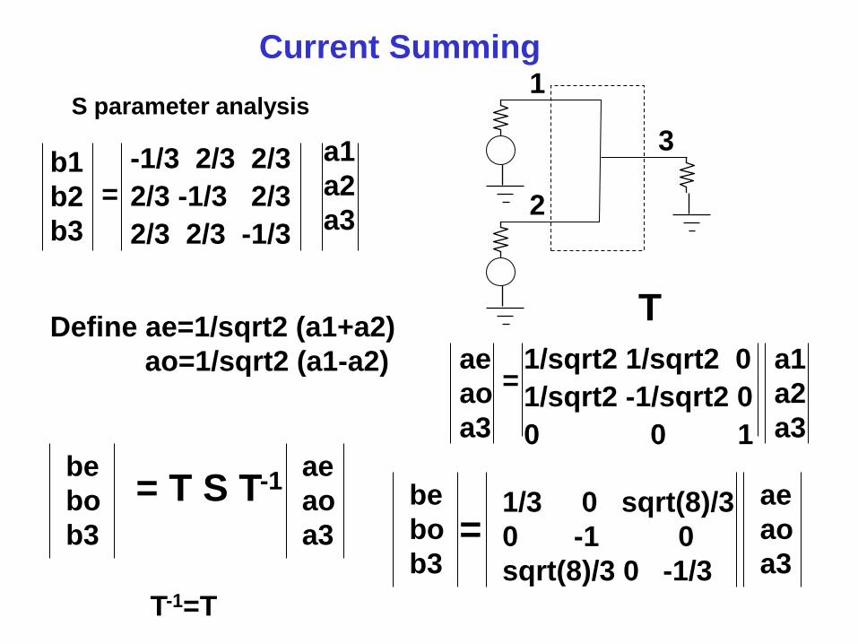
Current Summing
S parameter analysis 1
2
3 b1
b2
b3
-1/3 2/3 2/3
2/3 -1/3 2/3
2/3 2/3 -1/3
a1
a2
a3
Define ae=1/sqrt2 (a1+a2)
ao=1/sqrt2 (a1-a2)
T
be
bo
b3
= T S T-1 ae
ao
a3
=
1/sqrt2 1/sqrt2 0
1/sqrt2 -1/sqrt2 0
0 0 1
ae
ao
a3
a1
a2
a3
=
T-1=T
be
bo
b3 =
ae
ao
a3
1/3 0 sqrt(8)/3
0 -1 0
sqrt(8)/3 0 -1/3
freq
1.000 GHz
S(1,1)
0.333 / 1...
S(2,1)
0.667 / 0...
S(3,1)
0.667 / 0...
freq
1.000 ...
S(4,4)
0.333 ...
S(5,5)
1.000 ...
S(6,4)
0.943 ...
S(6,5)
0.000 ...
Eqn Zin=stoz(S)freq
1.000 GHz
Zin(4,4)
2.123E17 / 0....
Zin(5,5)
1.421E-14 / 0....
Eqn Zine=50*(1+S(4,4))/(1-S(4,4))
Eqn Zino=50*(1+S(5,5))/(1-S(5,5))
freq
1.000 GHz
Zine
100.000 / 0.000
Zino
1.388E-14 / 0....
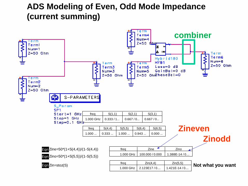
ADS Modeling of Even, Odd Mode Impedance
(current summing)
Zineven
Zinodd
combiner
Not what you want
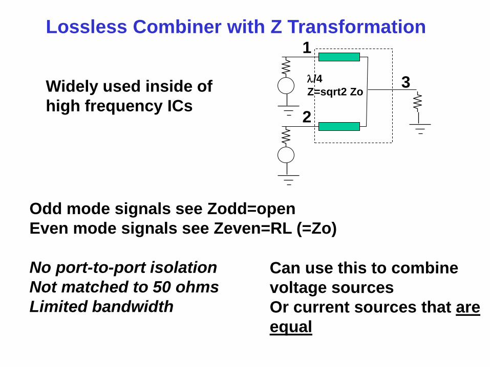
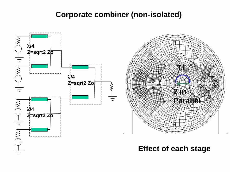
Lossless Combiner with Z Transformation
Widely used inside of
high frequency ICs
1
2
3
Odd mode signals see Zodd=open
Even mode signals see Zeven=RL (=Zo)
No port-to-port isolation
Not matched to 50 ohms
Limited bandwidth
Can use this to combine
voltage sources
Or current sources that are
equal
l/4
Z=sqrt2 Zo

l/4
Z=sqrt2 Zo
l/4
Z=sqrt2 Zo
l/4
Z=sqrt2 Zo
Corporate combiner (non-isolated)
Effect of each stage
T.L.
2 in
Parallel
Wilkinson Combiner
Widely used in circuit
boards and systems
Odd mode signals see Zodd= 50 ohms
Even mode signals see Zeven=RL (=Zo)
Ports are isolated!
Matched to 50 ohms!
Limited bandwidth
Can use this to combine
voltage or current sources
Get loss to the extent that
the sources are not equal
1
2
3 l/4
Z=sqrt2 Zo
R=2Zo
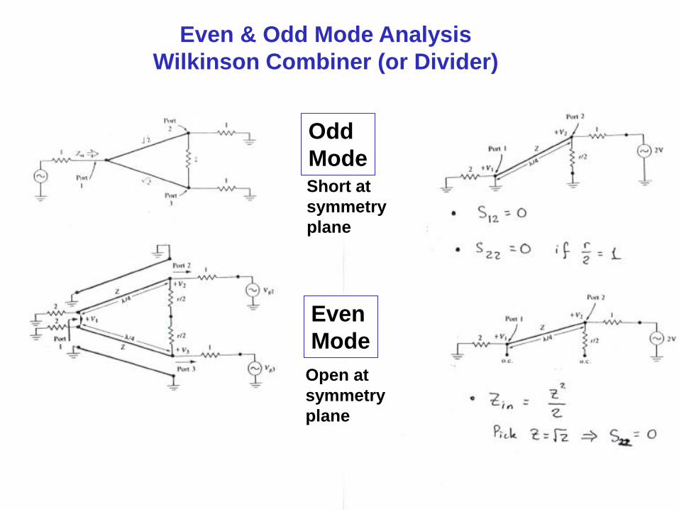
Even & Odd Mode Analysis
Wilkinson Combiner (or Divider)
Short at
symmetry
plane
Open at
symmetry
plane
Odd
Mode
Even
Mode
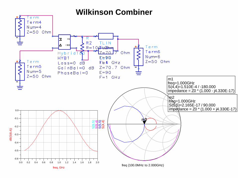
freq (100.0MHz to 2.000GHz)
S(4
,4)
1.000E91.510E-4 / -180.000
m1
S(5
,5)
Readout
m2
S(6
,4)
S(6
,5)
m1freq=S(4,4)=1.510E-4 / -180.000impedance = Z0 * (1.000 - j4.330E-17)
1.000GHz
m2freq=S(5,5)=2.165E-17 / 90.000impedance = Z0 * (1.000 + j4.330E-17)
1.000GHz
Wilkinson Combiner
0.2 0.4 0.6 0.8 1.0 1.2 1.4 1.6 1.80.0 2.0
-0.5
-0.4
-0.3
-0.2
-0.1
-0.6
0.0
freq, GHz
dB
(S(6
,4))
m1freq=S(1,1)=0.006 / 45.165impedance = Z0 * (1.008 + j0.008)
900.0MHz
m2freq=S(2,2)=1.000 / -96.478impedance = Z0 * (-1.611E-12 - j0.893)
1.000GHz
freq (100.0MHz to 2.000GHz)
S(1
,1)
9.000E80.006 / 45.165
m1
S(2
,2)
1.000E91.000 / -96.478
m2
m1freq=S(1,1)=0.006 / 45.165impedance = Z0 * (1.008 + j0.008)
900.0MHz
m2freq=S(2,2)=1.000 / -96.478impedance = Z0 * (-1.611E-12 - j0.893)
1.000GHz
0.2 0.4 0.6 0.8 1.0 1.2 1.4 1.6 1.80.0 2.0
-0.8
-0.6
-0.4
-0.2
-1.0
0.0
freq, GHz
dB
(S(3
,1))
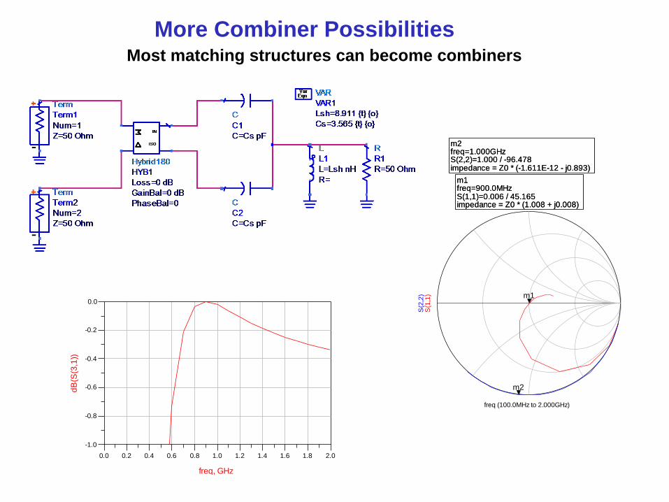
More Combiner Possibilities Most matching structures can become combiners

m1freq=S(1,1)=0.008 / -72.429impedance = Z0 * (1.005 - j0.015)
800.0MHz
m2freq=S(2,2)=1.000 / 78.143impedance = Z0 * (-2.256E-12 + j1.232)
1.000GHz
freq (100.0MHz to 2.000GHz)S
(1,1
)
8.000E80.070 / -39.239
m1
S(2
,2)
1.000E91.000 / 83.531
m2
m1freq=S(1,1)=0.008 / -72.429impedance = Z0 * (1.005 - j0.015)
800.0MHz
m2freq=S(2,2)=1.000 / 78.143impedance = Z0 * (-2.256E-12 + j1.232)
1.000GHz
0.2 0.4 0.6 0.8 1.0 1.2 1.4 1.6 1.80.0 2.0
-0.8
-0.6
-0.4
-0.2
-1.0
0.0
freq, GHz
dB
(S(3
,1))
More Combiner Possibilities Most matching structures can become combiners
0.5 1.0 1.5 2.0 2.5 3.0 3.5 4.0 4.50.0 5.0
100
150
200
250
50
300
a
ma
g(Z
1)
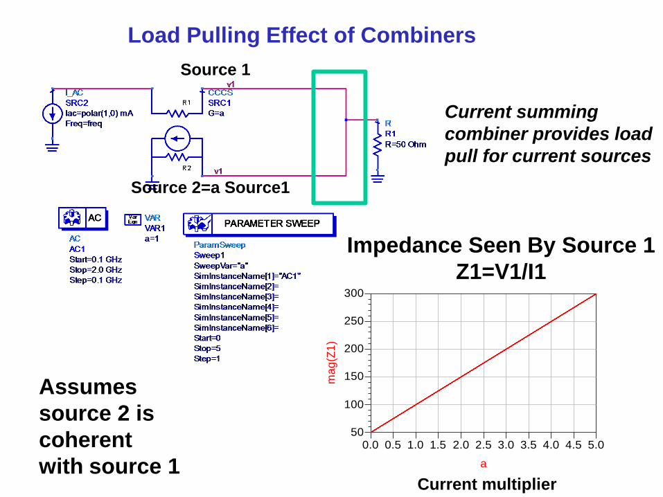
Impedance Seen By Source 1
Z1=V1/I1
Source 1
Source 2=a Source1
Current multiplier
Load Pulling Effect of Combiners
Current summing
combiner provides load
pull for current sources
Assumes
source 2 is
coherent
with source 1
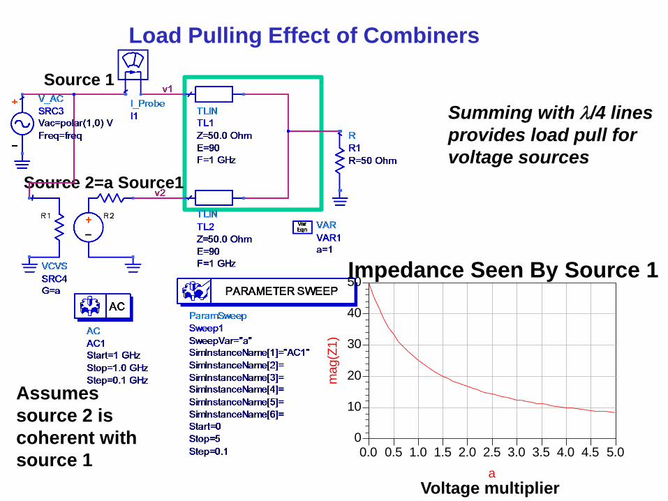
Impedance Seen By Source 1
Source 1
Source 2=a Source1
Voltage multiplier
Load Pulling Effect of Combiners
0.5 1.0 1.5 2.0 2.5 3.0 3.5 4.0 4.50.0 5.0
10
20
30
40
0
50
a
mag(Z
1)
Summing with l/4 lines
provides load pull for
voltage sources
Assumes
source 2 is
coherent with
source 1
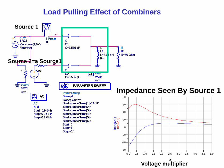
0.5 1.0 1.5 2.0 2.5 3.0 3.5 4.0 4.50.0 5.0
-40
-20
0
20
40
60
-60
80
a
rea
l(Z
1)
ima
g(Z
1)
Source 1
Source 2=a Source1
Load Pulling Effect of Combiners
Impedance Seen By Source 1
Voltage multiplier
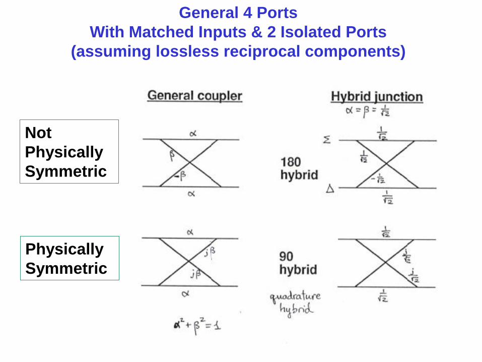
General 4 Ports
With Matched Inputs & 2 Isolated Ports
(assuming lossless reciprocal components)
Not
Physically
Symmetric
Physically
Symmetric
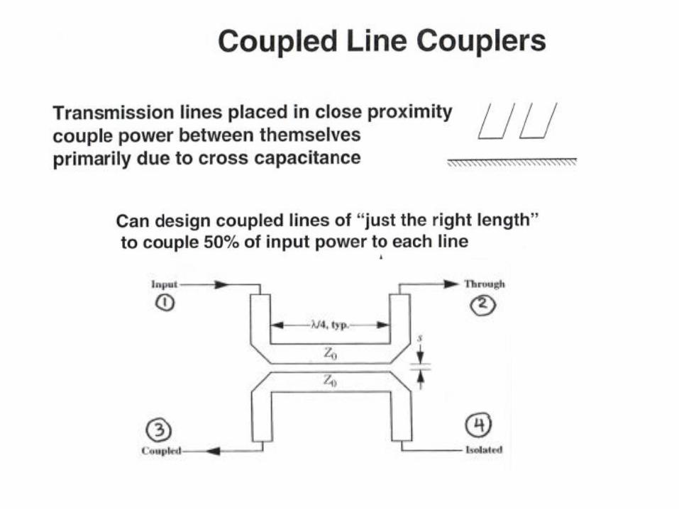
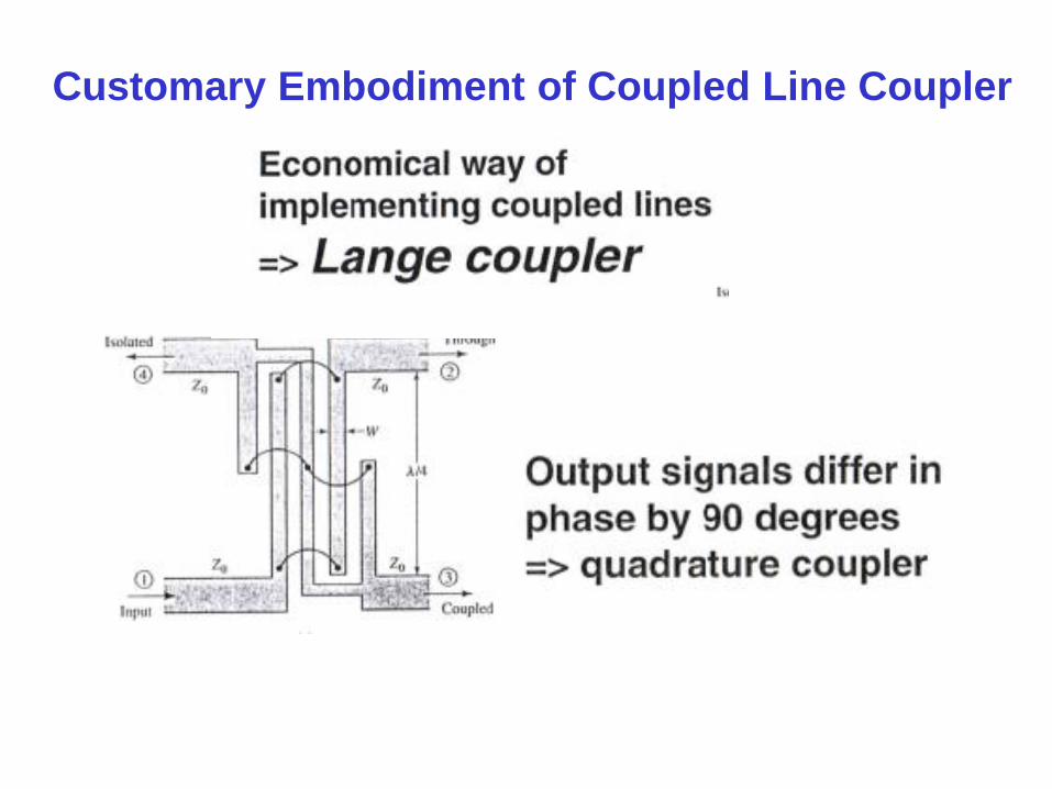
Customary Embodiment of Coupled Line Coupler
+
-
+
-
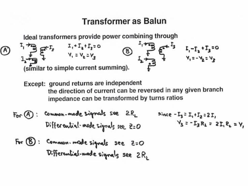
Differential
amplifier Balun Balun
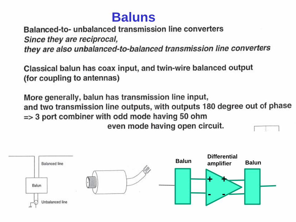
Baluns
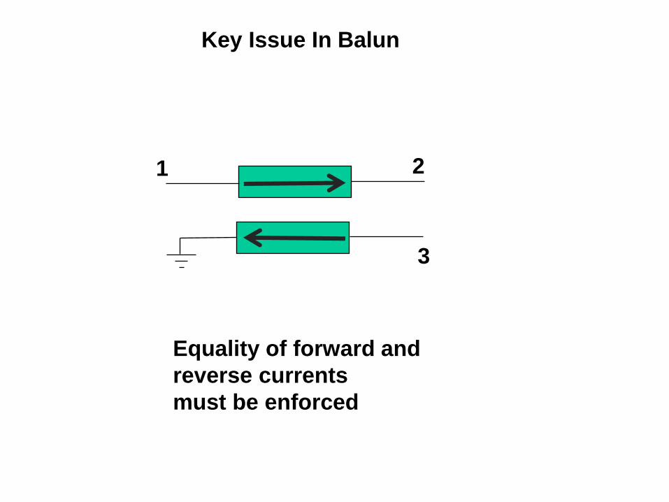
Key Issue In Balun
Equality of forward and
reverse currents
must be enforced
1 2
3
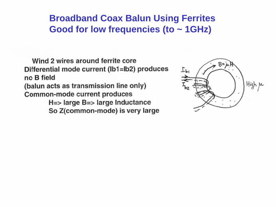
Broadband Coax Balun Using Ferrites
Good for low frequencies (to ~ 1GHz)
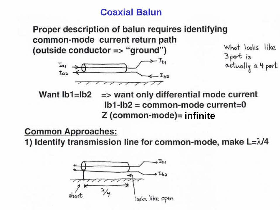
infinite
Coaxial Balun
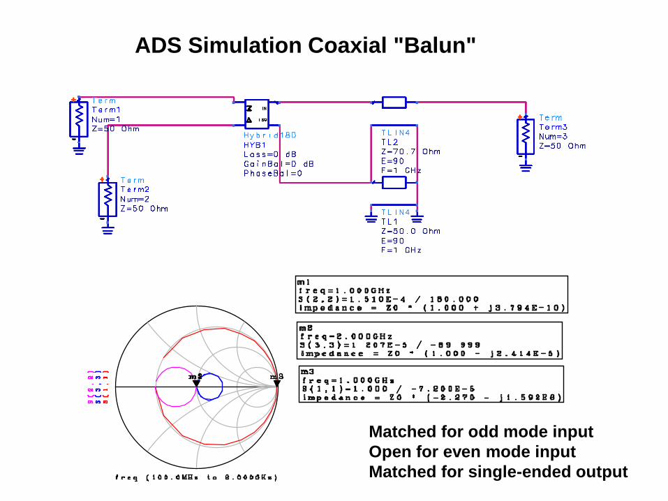
ADS Simulation Coaxial "Balun"
Matched for odd mode input
Open for even mode input
Matched for single-ended output
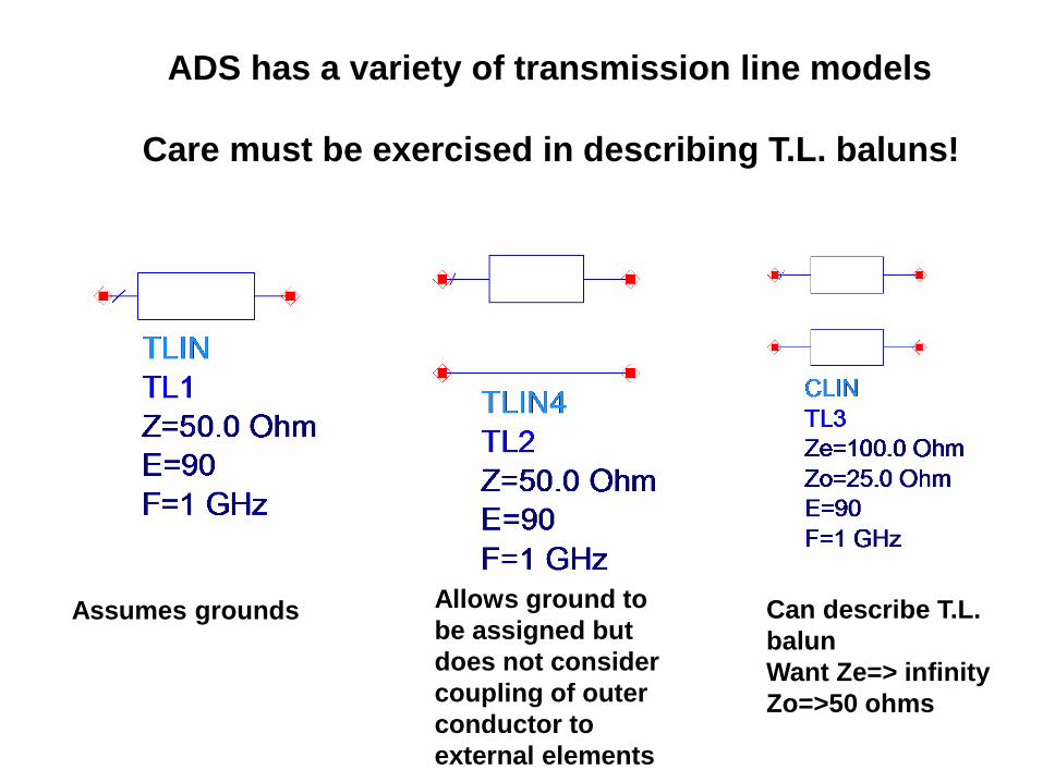
ADS has a variety of transmission line models
Care must be exercised in describing T.L. baluns!
Assumes grounds
Allows ground to
be assigned but
does not consider
coupling of outer
conductor to
external elements
Can describe T.L.
balun
Want Ze=> infinity
Zo=>50 ohms

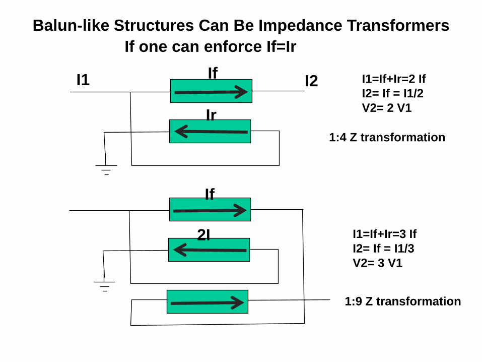
1:4 Z transformation
2I
Balun-like Structures Can Be Impedance Transformers
If one can enforce If=Ir
I1 If I2 I1=If+Ir=2 If
I2= If = I1/2
V2= 2 V1 Ir
I1=If+Ir=3 If
I2= If = I1/3
V2= 3 V1
1:9 Z transformation
If
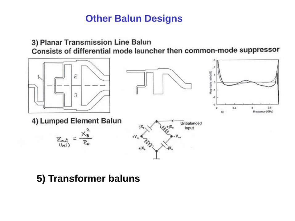
Other Balun Designs
5) Transformer baluns
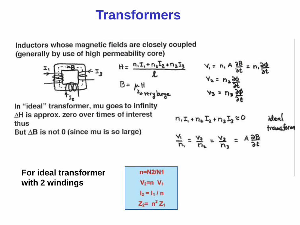
Transformers
For ideal transformer
with 2 windings
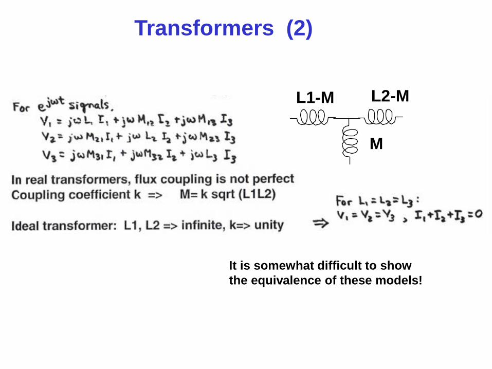
Transformers (2)
L1-M L2-M
M
It is somewhat difficult to show
the equivalence of these models!
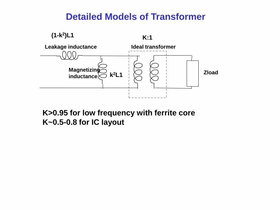
Ideal transformer
Zload
Leakage inductance
Magnetizing
inductance
Detailed Models of Transformer
(1-k2)L1
k2L1
K:1
K>0.95 for low frequency with ferrite core
K~0.5-0.8 for IC layout
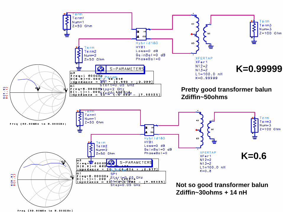
Pretty good transformer balun
Zdiffin~50ohms
Not so good transformer balun
Zdiffin~30ohms + 14 nH
K=0.99999
K=0.6
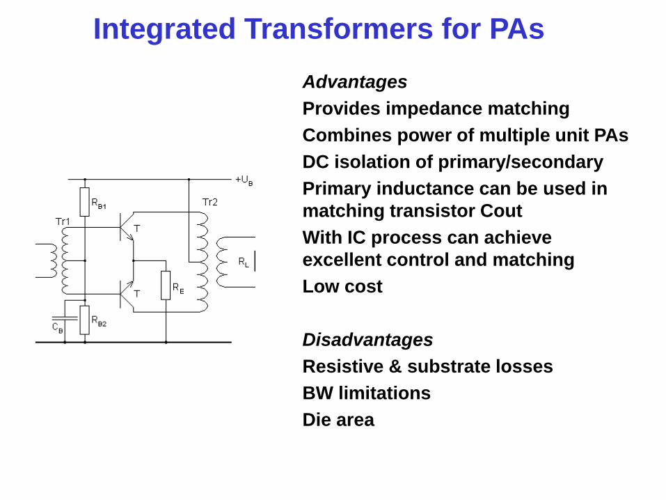
Integrated Transformers for PAs
Advantages
Provides impedance matching
Combines power of multiple unit PAs
DC isolation of primary/secondary
Primary inductance can be used in
matching transistor Cout
With IC process can achieve
excellent control and matching
Low cost
Disadvantages
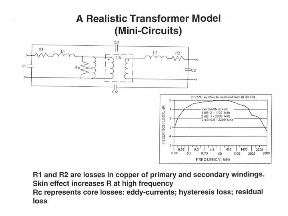
Resistive & substrate losses
BW limitations
Die area
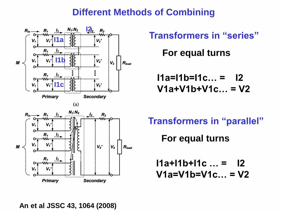
Transformers in “series” I1a
I1b
I1c
I2
For equal turns
I1a=I1b=I1c… = I2
V1a+V1b+V1c… = V2
Transformers in “parallel”
For equal turns
I1a+I1b+I1c … = I2
V1a=V1b=V1c… = V2
Different Methods of Combining
An et al JSSC 43, 1064 (2008)
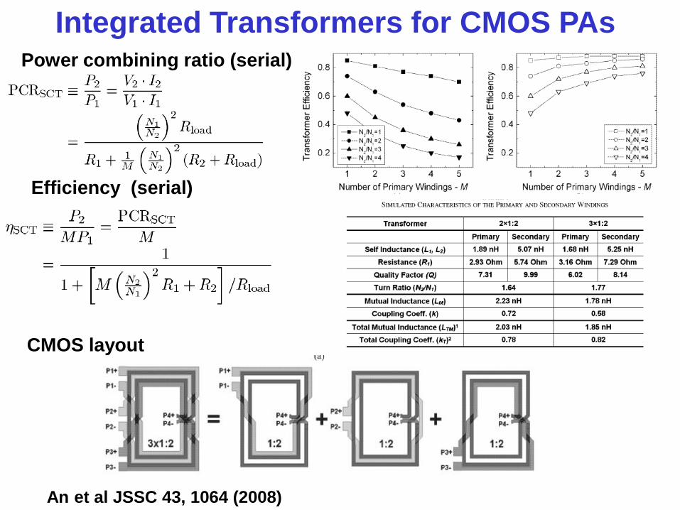
Integrated Transformers for CMOS PAs
An et al JSSC 43, 1064 (2008)
Power combining ratio (serial)
Efficiency (serial)
CMOS layout
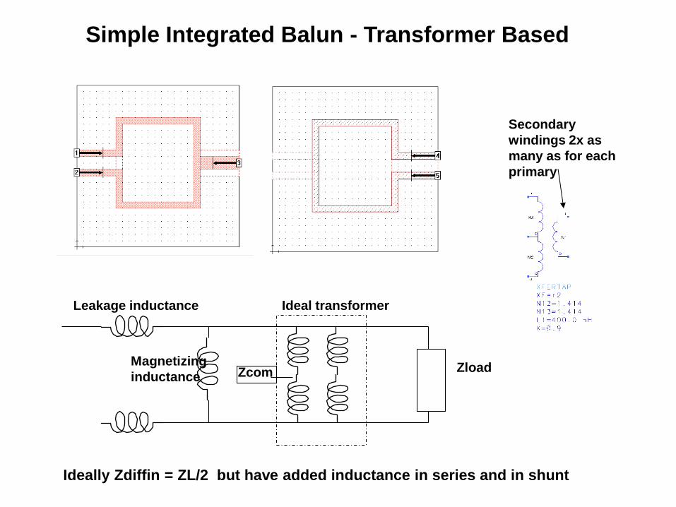
Simple Integrated Balun - Transformer Based
Secondary
windings 2x as
many as for each
primary
Ideal transformer
Zload Zcom
Leakage inductance
Magnetizing
inductance
Ideally Zdiffin = ZL/2 but have added inductance in series and in shunt
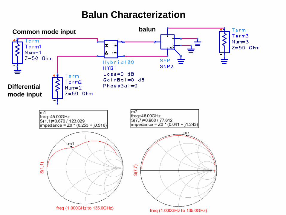
Balun Characterization
Common mode input
Differential
mode input
balun
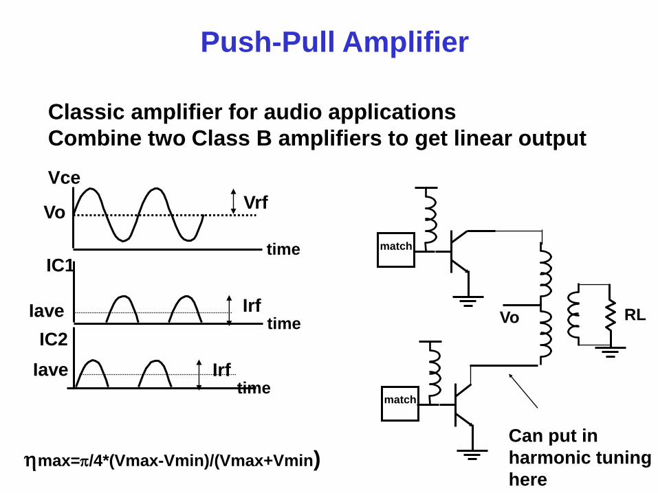
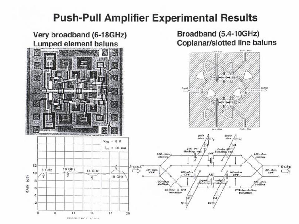
Push-Pull Amplifier
hmax=p/4*(Vmax-Vmin)/(Vmax+Vmin)
time
time
Vo
Vce
Iave
IC1
Vrf
Irf
Classic amplifier for audio applications
Combine two Class B amplifiers to get linear output
time Iave
IC2
Irf
match
Vo RL
match
Can put in
harmonic tuning
here
Benefits of Push-Pull Amplifier
•Gets rid of even harmonics
can be used for very wide bandwidths (more than x2)
in situations where filtering cannot be done
•Push pull leads to more uniform current draw from supply,
so grounding source is not a big problem
•The output voltage swing is double that for a single transistor
=> higher output impedance
Drawbacks
Need for balun: potentially lossy and bandwidth limiting
Push-pull suffers same IM3 distortion as single Class B!
Perfect Class B does not generate IM3
but low gm at low bias causes problems in real life
If both transistors “on” at same time, get cross-over distortion

Balanced Amplifiers
Commonly used arrangement with 2 amplifiers fed by signals coming
from a 90o splitter (ie Lange coupler)
90 degree
hybrid 90 degree
hybrid
j
j
j
j
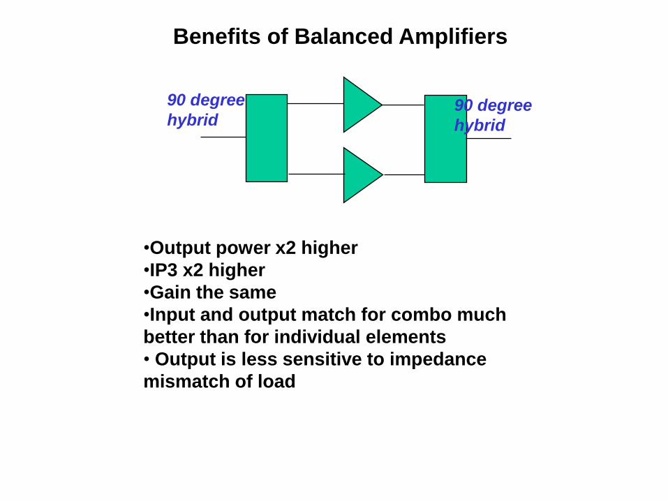
•Output power x2 higher
•IP3 x2 higher
•Gain the same
•Input and output match for combo much
better than for individual elements
• Output is less sensitive to impedance
mismatch of load
Benefits of Balanced Amplifiers
90 degree
hybrid 90 degree
hybrid

Effects of Amplitude and Phase Mismatch
-0.7
-0.6
-0.5
-0.4
-0.3
-0.2
-0.1
0
0 10 20 30 40 50
Angle of mismatch (degrees)
Co
mb
inin
g l
oss
(dB
)
r=1
r=1.2
a1
a2
b3
Would like r=1, q=0
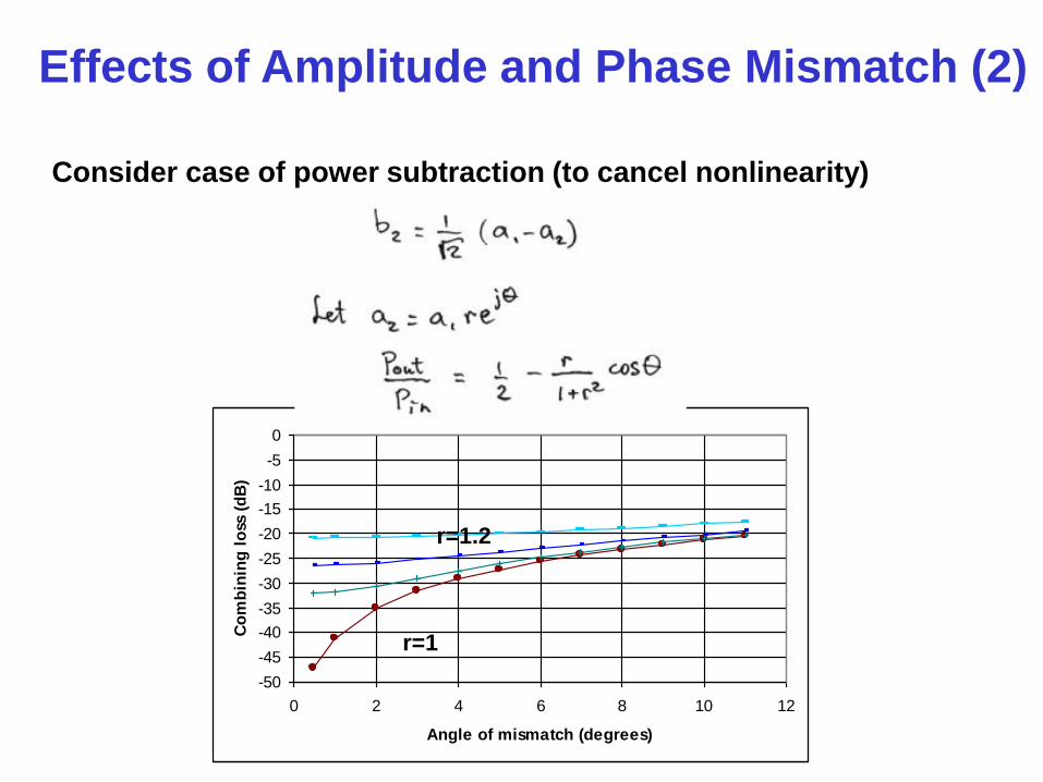
Effects of Amplitude and Phase Mismatch (2)
Consider case of power subtraction (to cancel nonlinearity)
-50
-45
-40
-35
-30
-25
-20
-15
-10
-5
0
0 2 4 6 8 10 12
Angle of mismatch (degrees)
Co
mb
inin
g l
oss
(d
B)
r=1
r=1.2