Embed Size (px)
Citation preview
MICROWAVE OVENSERVICE MANUALMODEL: MC-8483NLCAUTIONBEFORE SERVICING THE UNIT, READ THE SAFETY PRECAUTIONS IN THIS MANUAL.
Website http://biz.lgservice.com
P/NO : 3828W5S3700May, 2004
Printed in Korea
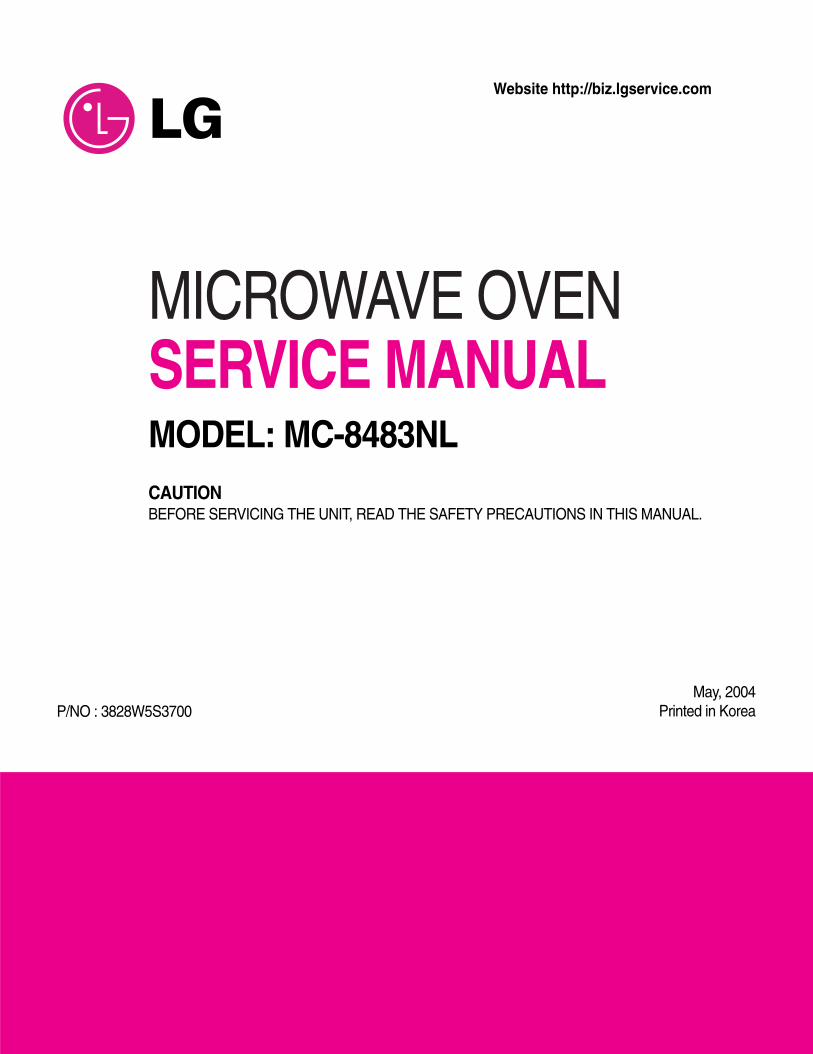
This device is to be serviced only by properly qualified service personnel.Consult the service manual for proper service procedures to assure continued safety operation and for precautions to betaken to avoid possible exposure to excessive microwave energy.
PRECAUTIONS TO BE OBSERVED BEFORE ANDDURING SERVICING TO AVOID POSSIBLEEXPOSURE TO EXCESSIVE MICROWAVE ENERGYA) Do not operate or allow the oven to be operated with the door open.
B) Make the following safety checks on all ovens to be serviced before activating the magnetron or other
microwave source, and make repairs as necessary; (1) interlock operation, (2) proper door closing, (3)
seal and sealing surfaces (arcing, wear, and other damage), (4) damage to or loosening of hinges and
latches, (5) evidence of dropping or abuse.
C) Before turning on microwave power for any service test or inspection within the microwave generating
compartments, check the magnetron, wave guide or transmission line, and cavity for proper alignment,
integrity, and connections.
D) Any defective or misadjusted components in the interlock, monitor, door seal, and microwave generation
and transmission systems shall be repaired, replaced, or adjusted by procedures described in this manual
before the oven is released to the owner.
E) A microwave leakage check to verify compliance with the Federal Performance Standard should be
performed on each oven prior to release to the owner.
SAFETY PRECAUTIONS
CAUTIONMICROWAVE RADIATION
DO NOT BECOME EXPOSED TO RADIATION FROM THE MICROWAVE GENERATOROR OTHER PARTS CONDUCTING MICROWAVE ENERGY.
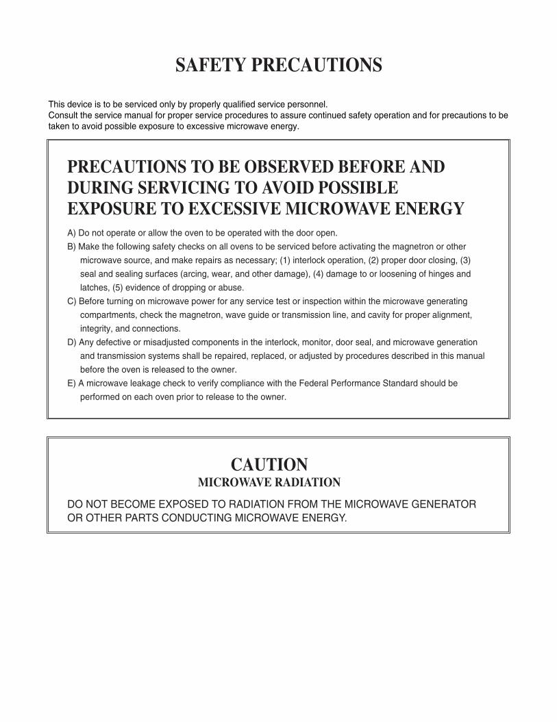
(Page)
SAFETY PRECAUTIONS - - - - - - - - - - - - - - - - - - - - - - - - - - - - - - - - - - - - - - - - - - - - - - - - - - - - - - - - - - - - - - - - - - - - - Inside front cover
SPECIFICATIONS - - - - - - - - - - - - - - - - - - - - - - - - - - - - - - - - - - - - - - - - - - - - - - - - - - - - - - - - - - - - - - - - - - - - - - - - - - - - - - - - - - - - - - - - - - - - - - - - - - - - - 1-1
CAUTIONS - - - - - - - - - - - - - - - - - - - - - - - - - - - - - - - - - - - - - - - - - - - - - - - - - - - - - - - - - - - - - - - - - - - - - - - - - - - - - - - - - - - - - - - - - - - - - - - - - - - - - - - - - - - - - - 2-1
INSTALLATIONS - - - - - - - - - - - - - - - - - - - - - - - - - - - - - - - - - - - - - - - - - - - - - - - - - - - - - - - - - - - - - - - - - - - - - - - - - - - - - - - - - - - - - - - - - - - - - - - - - - - - - - 3-1
OPERATING INSTRUCTIONS - - - - - - - - - - - - - - - - - - - - - - - - - - - - - - - - - - - - - - - - - - - - - - - - - - - - - - - - - - - - - - - - - - - - - - - - - - - - - - - - - - - - 4-1
FEATURES- - - - - - - - - - - - - - - - - - - - - - - - - - - - - - - - - - - - - - - - - - - - - - - - - - - - - - - - - - - - - - - - - - - - - - - - - - - - - - - - - - - - - - - - - - - - - - - - - - - - - - - - - - - - - - - - - - - - - - - - 4-1
CONTROL PANEL - - - - - - - - - - - - - - - - - - - - - - - - - - - - - - - - - - - - - - - - - - - - - - - - - - - - - - - - - - - - - - - - - - - - - - - - - - - - - - - - - - - - - - - - - - - - - - - - - - - - - - - - - - - - - - 4-1
OPERATING SEQUENCE- - - - - - - - - - - - - - - - - - - - - - - - - - - - - - - - - - - - - - - - - - - - - - - - - - - - - - - - - - - - - - - - - - - - - - - - - - - - - - - - - - - - - - - - - - - - - - - - - - - - 4-2
SCHEMATIC DIAGRAM - - - - - - - - - - - - - - - - - - - - - - - - - - - - - - - - - - - - - - - - - - - - - - - - - - - - - - - - - - - - - - - - - - - - - - - - - - - - - - - - - - - - - - - - - - - - - - - - - - - - - - 4-3
CIRCUIT DESCRIPTION - - - - - - - - - - - - - - - - - - - - - - - - - - - - - - - - - - - - - - - - - - - - - - - - - - - - - - - - - - - - - - - - - - - - - - - - - - - - - - - - - - - - - - - - - - - - - - - - - - - - - 4-4
SERVICE INFORMATION - - - - - - - - - - - - - - - - - - - - - - - - - - - - - - - - - - - - - - - - - - - - - - - - - - - - - - - - - - - - - - - - - - - - - - - - - - - - - - - - - - - - - - - - - - 5-1
TOOLS AND MEASURING INSTRUMENTS - - - - - - - - - - - - - - - - - - - - - - - - - - - - - - - - - - - - - - - - - - - - - - - - - - - - - - - - - - - - - - - - - - - - - - - - - - - 5-1
MICROWAVE LEAKAGE TEST - - - - - - - - - - - - - - - - - - - - - - - - - - - - - - - - - - - - - - - - - - - - - - - - - - - - - - - - - - - - - - - - - - - - - - - - - - - - - - - - - - - - - - - - - - - - 5-1
MEASUREMENT OF MICROWAVE POWER OUTPUT - - - - - - - - - - - - - - - - - - - - - - - - - - - - - - - - - - - - - - - - - - - - - - - - - - - - - - - - - - - 5-3
DISASSEMBLY AND ADJUSTMENT - - - - - - - - - - - - - - - - - - - - - - - - - - - - - - - - - - - - - - - - - - - - - - - - - - - - - - - - - - - - - - - - - - - - - - - - - - - - - - - - - - - - - 5-3
INTERLOCK CONTINUITY TEST- - - - - - - - - - - - - - - - - - - - - - - - - - - - - - - - - - - - - - - - - - - - - - - - - - - - - - - - - - - - - - - - - - - - - - - - - - - - - - - - - - - - - - - - - - 5-7
COMPONENT TEST PROCEDURE - - - - - - - - - - - - - - - - - - - - - - - - - - - - - - - - - - - - - - - - - - - - - - - - - - - - - - - - - - - - - - - - - - - - - - - - - - - - - - - - - - - - - - 5-8
TROUBLE SHOOTING - - - - - - - - - - - - - - - - - - - - - - - - - - - - - - - - - - - - - - - - - - - - - - - - - - - - - - - - - - - - - - - - - - - - - - - - - - - - - - - - - - - - - - - - - - - - - - - - - - - - - - 5-13
EXPLODED VIEW - - - - - - - - - - - - - - - - - - - - - - - - - - - - - - - - - - - - - - - - - - - - - - - - - - - - - - - - - - - - - - - - - - - - - - - - - - - - - - - - - - - - - - - - - - - - - - - - 6-1
REPLACEMENT PARTS LIST - - - - - - - - - - - - - - - - - - - - - - - - - - - - - - - - - - - - - - - - - - - - - - - - - - - - - - - - - - - - - - - - - - - - - - - - - - - - - - - - - - - - 7-1
CONTENTS
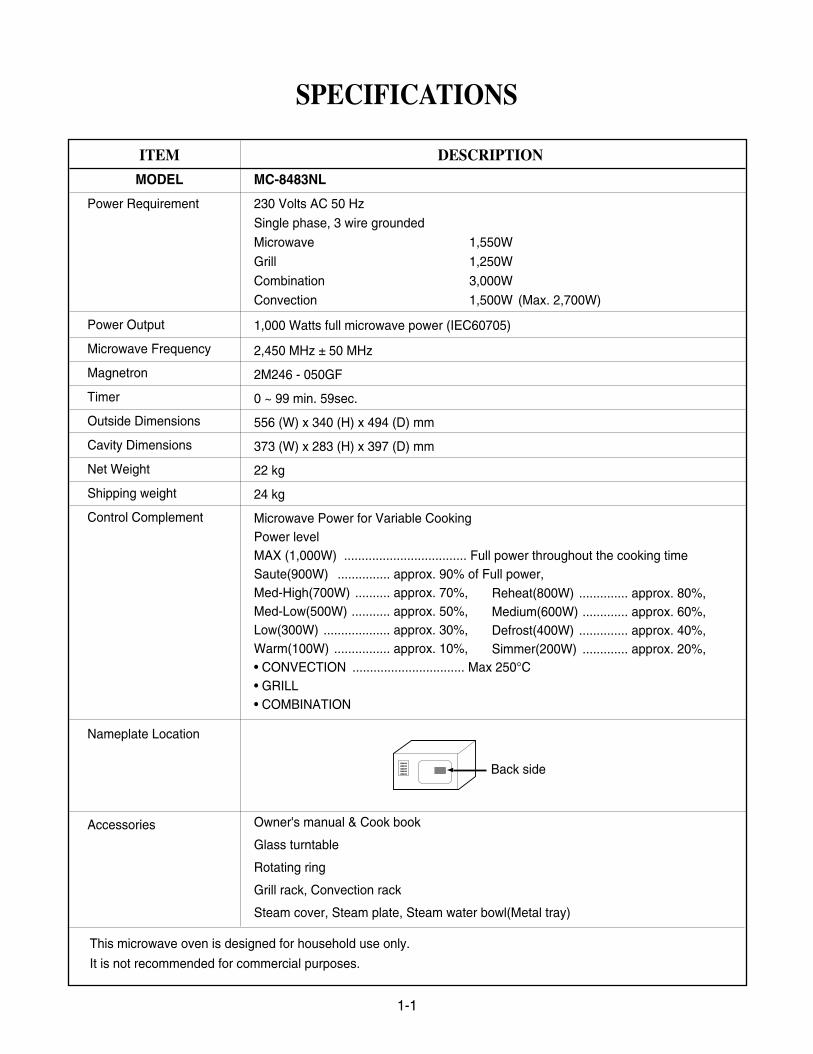
This microwave oven is designed for household use only.
It is not recommended for commercial purposes.
DESCRIPTION
MC-8483NL
230 Volts AC 50 Hz
Single phase, 3 wire grounded
Microwave 1,550W
Grill 1,250W
Combination 3,000W
Convection 1,500W (Max. 2,700W)
1,000 Watts full microwave power (IEC60705)
2,450 MHz ± 50 MHz
2M246 - 050GF
0 ~ 99 min. 59sec.
556 (W) x 340 (H) x 494 (D) mm
373 (W) x 283 (H) x 397 (D) mm
22 kg
24 kg
Microwave Power for Variable CookingPower levelMAX (1,000W) ................................... Full power throughout the cooking timeSaute(900W) ............... approx. 90% of Full power,Med-High(700W) .......... approx. 70%,Med-Low(500W) ........... approx. 50%, Low(300W) ................... approx. 30%,Warm(100W) ................ approx. 10%, • CONVECTION ................................ Max 250°C• GRILL• COMBINATION
Owner's manual & Cook book
Glass turntable
Rotating ring
Grill rack, Convection rack
Steam cover, Steam plate, Steam water bowl(Metal tray)
1-1
ITEM
MODEL
Power Requirement
Power Output
Microwave Frequency
Magnetron
Timer
Outside Dimensions
Cavity Dimensions
Net Weight
Shipping weight
Control Complement
Nameplate Location
Accessories
SPECIFICATIONS
Back side
Reheat(800W) .............. approx. 80%,Medium(600W) ............. approx. 60%,Defrost(400W) .............. approx. 40%,Simmer(200W) ............. approx. 20%,
• DO NOT operate on a 2-wire extension cord duringrepair and use.
• NEVER TOUCH any oven components or wiring duringoperation.
• BEFORE TOUCHING any parts of the oven, alwaysremove the power plug from the outlet.
• For about 30 seconds after the oven stops, an electriccharge remains in the high voltage capacitor. Whenreplacing or checking, you must discharge the highvoltage capacitor by shorting across the two terminalswith an insulated screwdriver.
• Remove your watches whenever working close to orreplacing the Magnetron.
• NEVER operate the oven with no load.• NEVER injure the door seal and front plate of the oven
cavity.• NEVER put iron tools on the magnetron.• NEVER put anything into the latch hole and the
interlock switches area.
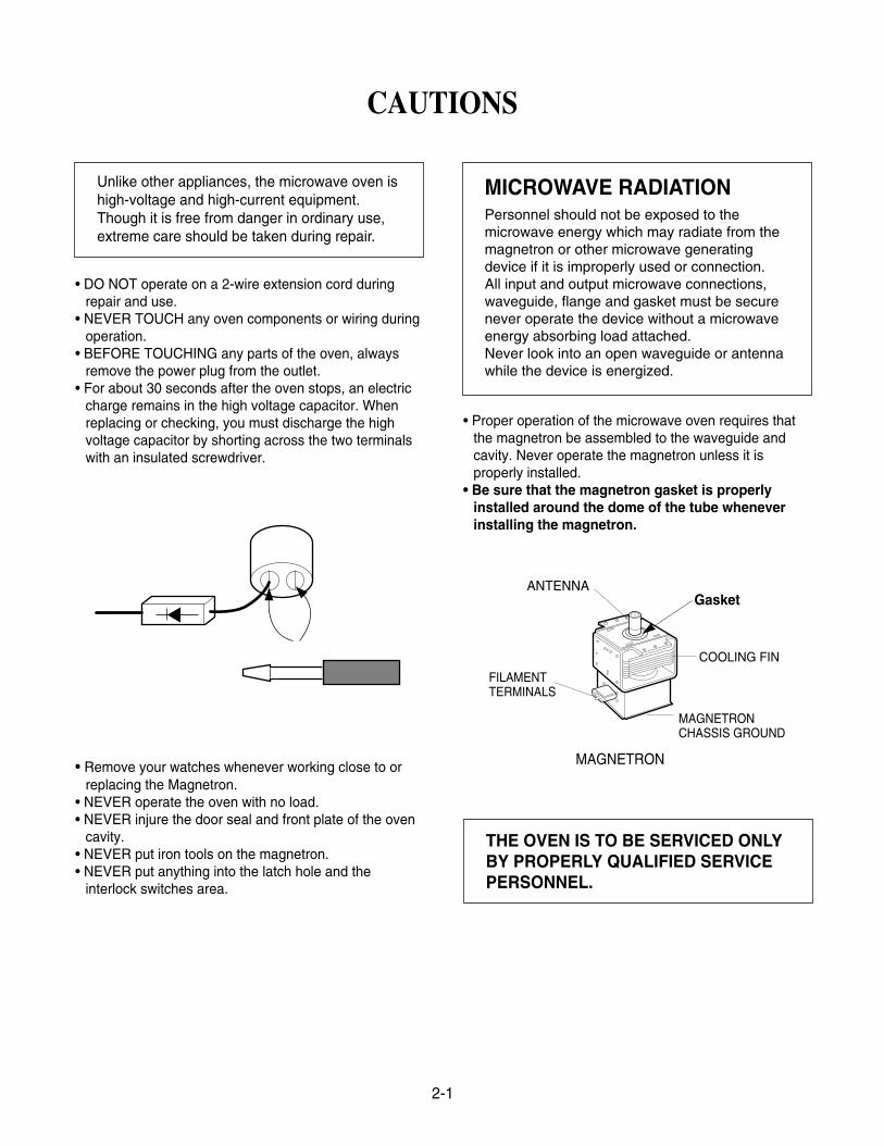
• Proper operation of the microwave oven requires thatthe magnetron be assembled to the waveguide andcavity. Never operate the magnetron unless it isproperly installed.
• Be sure that the magnetron gasket is properlyinstalled around the dome of the tube wheneverinstalling the magnetron.
2-1
CAUTIONS
Unlike other appliances, the microwave oven ishigh-voltage and high-current equipment.Though it is free from danger in ordinary use,extreme care should be taken during repair.
THE OVEN IS TO BE SERVICED ONLYBY PROPERLY QUALIFIED SERVICEPERSONNEL.
MICROWAVE RADIATIONPersonnel should not be exposed to themicrowave energy which may radiate from themagnetron or other microwave generatingdevice if it is improperly used or connection.All input and output microwave connections,waveguide, flange and gasket must be securenever operate the device without a microwaveenergy absorbing load attached.Never look into an open waveguide or antennawhile the device is energized.
GasketANTENNA
COOLING FIN
MAGNETRONCHASSIS GROUND
FILAMENTTERMINALS
MAGNETRON
INSTALLATIONS
3-1
INSTALLING1. Empty the microwave oven and clean inside it with
a soft, damp cloth. Check for damage such asmisaligned door, damage around the door or dentsinside the cavity or on the exterior.
2. Put the oven on a counter, table, or shelf that isstrong enough to hold the oven and the food andutensils you put in it. (The control panel side of theoven is the heavy side. Use care when handling.)
3. Do not block the vent and the air intake openings.Blocking vent or air intake openings can causedamage to the oven and poor cooking results.Make sure the microwave oven legs are in place toensure proper air flow.
4. The oven should not be installed in any area whereheat and steam are generated, because they maydamage the electronic or mechanical parts of theunit.Do not install the oven next to a conventionalsurface unit or above a conventional wall oven.
5. Use microwave oven in an ambient temperatureless than 104°F(40°C).
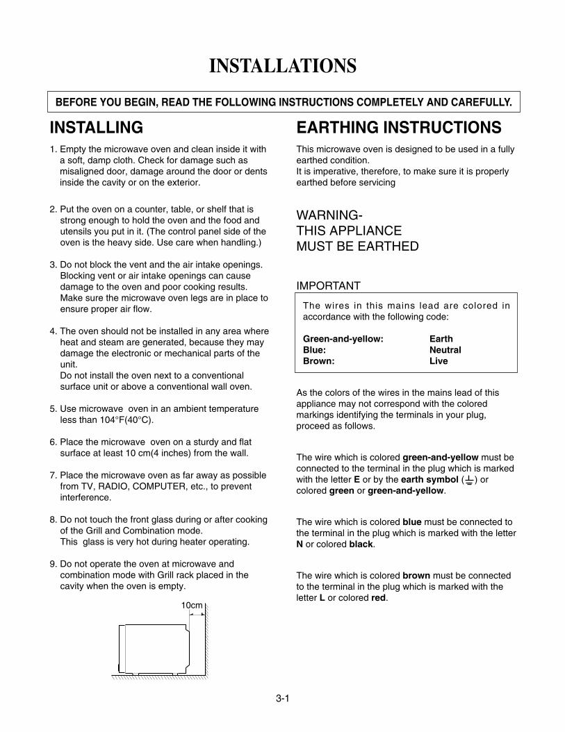
6. Place the microwave oven on a sturdy and flatsurface at least 10 cm(4 inches) from the wall.
7. Place the microwave oven as far away as possiblefrom TV, RADIO, COMPUTER, etc., to preventinterference.
8. Do not touch the front glass during or after cookingof the Grill and Combination mode.This glass is very hot during heater operating.
9. Do not operate the oven at microwave andcombination mode with Grill rack placed in thecavity when the oven is empty.
EARTHING INSTRUCTIONSThis microwave oven is designed to be used in a fullyearthed condition.It is imperative, therefore, to make sure it is properlyearthed before servicing
WARNING-THIS APPLIANCEMUST BE EARTHED
IMPORTANT
As the colors of the wires in the mains lead of thisappliance may not correspond with the coloredmarkings identifying the terminals in your plug,proceed as follows.
The wire which is colored green-and-yellow must beconnected to the terminal in the plug which is markedwith the letter E or by the earth symbol ( ) orcolored green or green-and-yellow.
The wire which is colored blue must be connected tothe terminal in the plug which is marked with the letterN or colored black.
The wire which is colored brown must be connectedto the terminal in the plug which is marked with theletter L or colored red.
BEFORE YOU BEGIN, READ THE FOLLOWING INSTRUCTIONS COMPLETELY AND CAREFULLY.
10cm
The wires in this mains lead are colored inaccordance with the following code:
Green-and-yellow: EarthBlue: NeutralBrown: Live
4-1
OPERATING INSTRUCTIONS
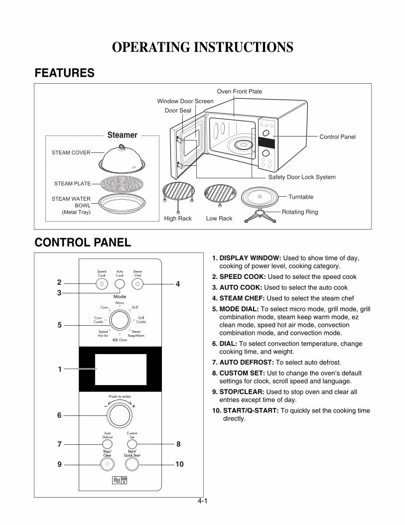
FEATURES
CONTROL PANEL1. DISPLAY WINDOW: Used to show time of day,
cooking of power level, cooking category.
2. SPEED COOK: Used to select the speed cook
3. AUTO COOK: Used to select the auto cook
4. STEAM CHEF: Used to select the steam chef
5. MODE DIAL: To select micro mode, grill mode, grillcombination mode, steam keep warm mode, ez clean mode, speed hot air mode, convectioncombination mode, and convection mode.
6. DIAL: To select convection temperature, changecooking time, and weight.
7. AUTO DEFROST: To select auto defrost.
8. CUSTOM SET: Ust to change the oven’s defaultsettings for clock, scroll speed and language.
9. STOP/CLEAR: Used to stop oven and clear all entries except time of day.
10. START/Q-START: To quickly set the cooking timedirectly.
Turntable
Rotating Ring
Safety Door Lock System
High Rack Low Rack
Oven Front Plate
Window Door Screen
Door Seal
Control PanelSteamer
STEAM COVER
STEAM PLATE
STEAM WATER BOWL
(Metal Tray)
23
5
6
7
9
1
4
8
10
4-2
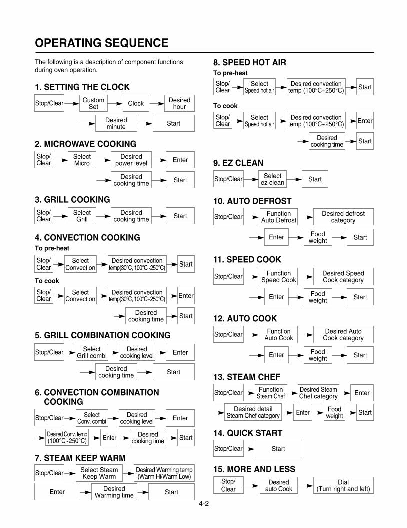
OPERATING SEQUENCEThe following is a description of component functionsduring oven operation.
1. SETTING THE CLOCK
2. MICROWAVE COOKING
3. GRILL COOKING
4. CONVECTION COOKINGTo pre-heat
To cook
5. GRILL COMBINATION COOKING
6. CONVECTION COMBINATIONCOOKING
7. STEAM KEEP WARM
8. SPEED HOT AIRTo pre-heat
To cook
9. EZ CLEAN
10. AUTO DEFROST
11. SPEED COOK
12. AUTO COOK
13. STEAM CHEF
14. QUICK START
15. MORE AND LESS
Stop/Clear CustomSet Clock
Desiredminute Start
Desiredhour
Stop/Clear
SelectMicro
Desiredpower level
Desiredcooking time Start
Desiredcooking time Start
Enter
Stop/Clear
SelectGrill
Desiredcooking time Start
Stop/Clear
SelectConvection
Desired convectiontemp(30°C, 100°C~250°C) Start
Stop/Clear
SelectConvection
Desired convectiontemp(30°C, 100°C~250°C) Enter
Stop/Clear SelectGrill combi
Desiredcooking level
Desiredcooking time Start
Enter
Stop/Clear SelectConv. combi
Desiredcooking level Enter
Stop/Clear Select SteamKeep Warm
Desired Warming temp(Warm Hi/Warm Low)
Enter DesiredWarming time Start
Desired Conv. temp(100°C~250°C) Enter Desired
cooking time Start
Stop/Clear
SelectSpeed hot air
Desired convectiontemp (100°C~250°C) Start
Stop/Clear
SelectSpeed hot air
Desired convectiontemp (100°C~250°C) Enter
Desiredcooking time Start
Stop/Clear Selectez clean Start
Enter Foodweight Start
Stop/Clear FunctionAuto Defrost
Desired defrostcategory
Enter Foodweight Start
Stop/Clear FunctionSpeed Cook
Desired SpeedCook category
Enter Foodweight Start
Stop/Clear FunctionAuto Cook
Desired Auto Cook category
Stop/Clear FunctionSteam Chef
Desired SteamChef category Enter
Desired detailSteam Chef category Enter Food
weight Start
Stop/Clear Start
Stop/Clear
Desiredauto Cook
Dial(Turn right and left)
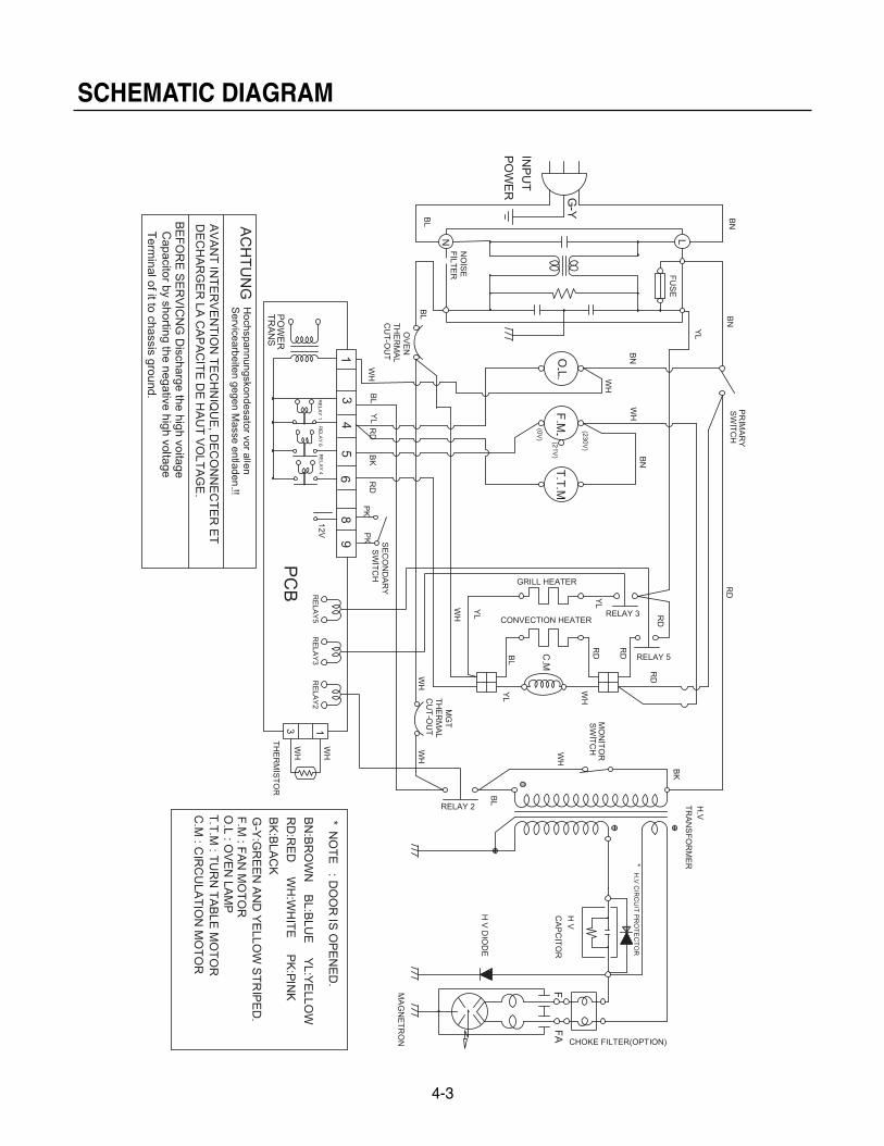
SCHEMATIC DIAGRAM
4-3
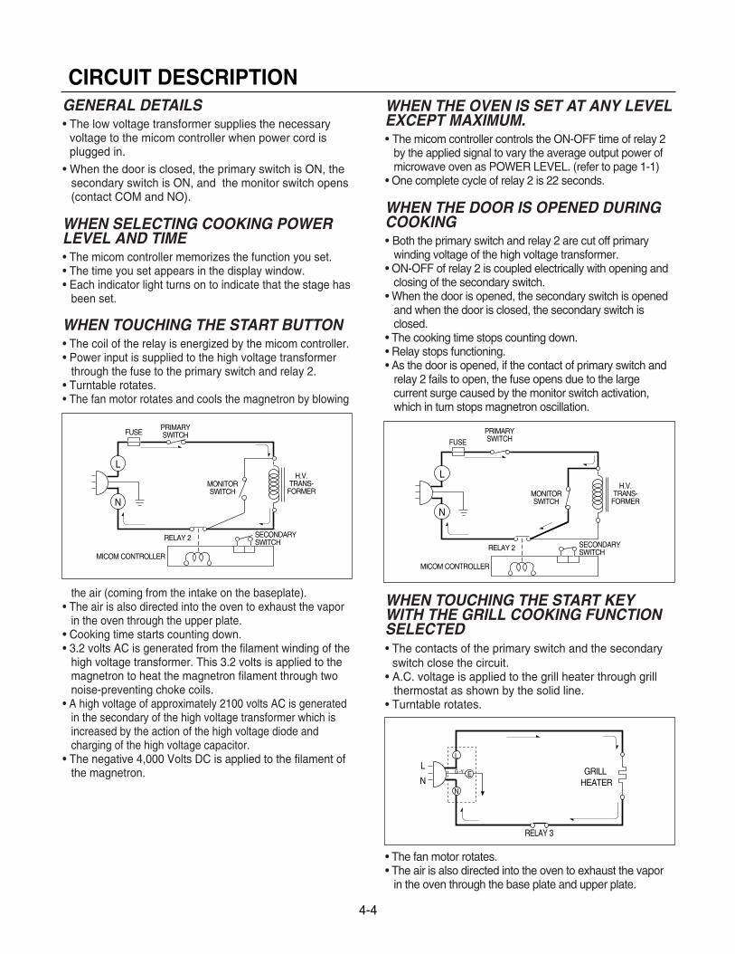
4-4
CIRCUIT DESCRIPTIONGENERAL DETAILS• The low voltage transformer supplies the necessary
voltage to the micom controller when power cord isplugged in.
• When the door is closed, the primary switch is ON, thesecondary switch is ON, and the monitor switch opens(contact COM and NO).
WHEN SELECTING COOKING POWERLEVEL AND TIME• The micom controller memorizes the function you set.• The time you set appears in the display window.• Each indicator light turns on to indicate that the stage has
been set.
WHEN TOUCHING THE START BUTTON• The coil of the relay is energized by the micom controller.• Power input is supplied to the high voltage transformer
through the fuse to the primary switch and relay 2.• Turntable rotates.• The fan motor rotates and cools the magnetron by blowing
the air (coming from the intake on the baseplate).• The air is also directed into the oven to exhaust the vapor
in the oven through the upper plate.• Cooking time starts counting down.• 3.2 volts AC is generated from the filament winding of the
high voltage transformer. This 3.2 volts is applied to themagnetron to heat the magnetron filament through twonoise-preventing choke coils.
• A high voltage of approximately 2100 volts AC is generatedin the secondary of the high voltage transformer which isincreased by the action of the high voltage diode andcharging of the high voltage capacitor.
• The negative 4,000 Volts DC is applied to the filament ofthe magnetron.
WHEN THE OVEN IS SET AT ANY LEVELEXCEPT MAXIMUM.• The micom controller controls the ON-OFF time of relay 2
by the applied signal to vary the average output power ofmicrowave oven as POWER LEVEL. (refer to page 1-1)
• One complete cycle of relay 2 is 22 seconds.
WHEN THE DOOR IS OPENED DURINGCOOKING• Both the primary switch and relay 2 are cut off primary
winding voltage of the high voltage transformer.• ON-OFF of relay 2 is coupled electrically with opening and
closing of the secondary switch.• When the door is opened, the secondary switch is opened
and when the door is closed, the secondary switch isclosed.
• The cooking time stops counting down.• Relay stops functioning.• As the door is opened, if the contact of primary switch and
relay 2 fails to open, the fuse opens due to the largecurrent surge caused by the monitor switch activation,which in turn stops magnetron oscillation.
WHEN TOUCHING THE START KEYWITH THE GRILL COOKING FUNCTIONSELECTED• The contacts of the primary switch and the secondary
switch close the circuit.• A.C. voltage is applied to the grill heater through grill
thermostat as shown by the solid line.• Turntable rotates.
• The fan motor rotates.• The air is also directed into the oven to exhaust the vapor
in the oven through the base plate and upper plate.
L
FUSE
H.V.TRANS-
FORMER
RELAY 2
MICOM CONTROLLER
SECONDARYSWITCH
PRIMARYSWITCH
N
MONITORSWITCH
L
FUSE
H.V.TRANS-
FORMER
RELAY 2
MICOM CONTROLLER
SECONDARYSWITCH
PRIMARYSWITCH
N
MONITORSWITCH
RELAY 3
L
NGRILL
HEATER
L
G -Y
N
E
CAUTIONS
• Be sure to check microwave leakage prior toservicing the oven if the oven is operative prior toservicing.
• The service personnel should inform themanufacture importer, or assembler of anycertified oven unit found to have a microwaveemission level in excess of 5 mW/cm2 and shouldrepair any unit found to have excessive emission levelsat no cost to the owner and should ascertain the causeof the excessive leakage. The service personnelshould instruct the owner not to use the unit until theoven has been brought into compliance.
• If the oven operates with the door open, the servicepersonnel should:- Tell the user not to operate the oven.- Contact the manufacturer.
• The service personnel should check all surface andvent openings for microwave leakage.
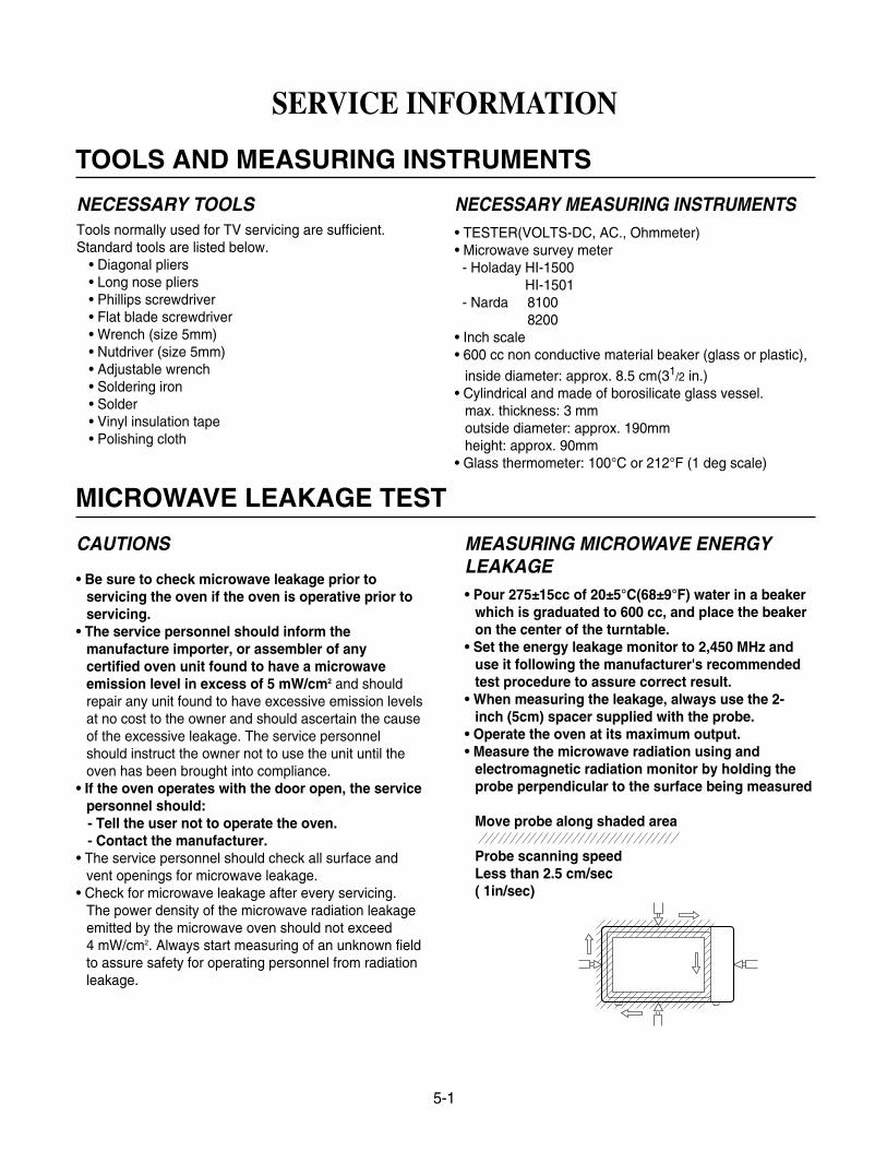
• Check for microwave leakage after every servicing.The power density of the microwave radiation leakageemitted by the microwave oven should not exceed 4 mW/cm2. Always start measuring of an unknown fieldto assure safety for operating personnel from radiationleakage.
MEASURING MICROWAVE ENERGYLEAKAGE• Pour 275±15cc of 20±5°C(68±9°F) water in a beaker
which is graduated to 600 cc, and place the beakeron the center of the turntable.
• Set the energy leakage monitor to 2,450 MHz anduse it following the manufacturer's recommendedtest procedure to assure correct result.
• When measuring the leakage, always use the 2-inch (5cm) spacer supplied with the probe.
• Operate the oven at its maximum output.• Measure the microwave radiation using and
electromagnetic radiation monitor by holding theprobe perpendicular to the surface being measured
Move probe along shaded area
Probe scanning speedLess than 2.5 cm/sec( 1in/sec)
5-1
SERVICE INFORMATION
TOOLS AND MEASURING INSTRUMENTS
MICROWAVE LEAKAGE TEST
NECESSARY TOOLSTools normally used for TV servicing are sufficient.Standard tools are listed below.
• Diagonal pliers• Long nose pliers• Phillips screwdriver• Flat blade screwdriver• Wrench (size 5mm)• Nutdriver (size 5mm)• Adjustable wrench• Soldering iron• Solder• Vinyl insulation tape• Polishing cloth
NECESSARY MEASURING INSTRUMENTS• TESTER(VOLTS-DC, AC., Ohmmeter)• Microwave survey meter- Holaday HI-1500
HI-1501- Narda 8100
8200• Inch scale• 600 cc non conductive material beaker (glass or plastic),
inside diameter: approx. 8.5 cm(31/2 in.)• Cylindrical and made of borosilicate glass vessel.
max. thickness: 3 mmoutside diameter: approx. 190mmheight: approx. 90mm
• Glass thermometer: 100°C or 212°F (1 deg scale)
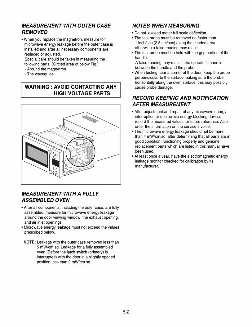
MEASUREMENT WITH OUTER CASEREMOVED• When you replace the magnetron, measure for
microwave energy leakage before the outer case isinstalled and after all necessary components arereplaced or adjusted.Special care should be taken in measuring thefollowing parts. (Circled area of below Fig.)- Around the magnetron- The waveguide
MEASUREMENT WITH A FULLYASSEMBLED OVEN• After all components, including the outer case, are fully
assembled, measure for microwave energy leakagearound the door viewing window, the exhaust opening,and air inlet openings.
• Microwave energy leakage must not exceed the valuesprescribed below.
NOTE: Leakage with the outer case removed less than5 mW/cm.sq. Leakage for a fully assembledoven (Before the latch switch (primary) isinterrupted) with the door in a slightly openedposition-less than 2 mW/cm.sq.
NOTES WHEN MEASURING• Do not exceed meter full scale deflection.• The test probe must be removed no faster than
1 inch/sec (2.5 cm/sec) along the shaded area,otherwise a false reading may result.
• The test probe must be held with the grip portion of thehandle.A false reading may result if the operator's hand isbetween the handle and the probe.
• When testing near a corner of the door, keep the probeperpendicular to the surface making sure the probehorizontally along the oven surface, this may possiblycause probe damage.
RECORD KEEPING AND NOTIFICATIONAFTER MEASUREMENT• After adjustment and repair of any microwave energy
interruption or microwave energy blocking device,record the measured values for future reference. Alsoenter the information on the service invoice.
• The microwave energy leakage should not be morethan 4 mW/cm.sq. after determining that all parts are ingood condition, functioning properly and genuinereplacement parts which are listed in this manual havebeen used.
• At least once a year, have the electromagnetic energyleakage monitor checked for calibration by itsmanufacturer.
WARNING : AVOID CONTACTING ANY HIGH VOLTAGE PARTS
5-2
5-3
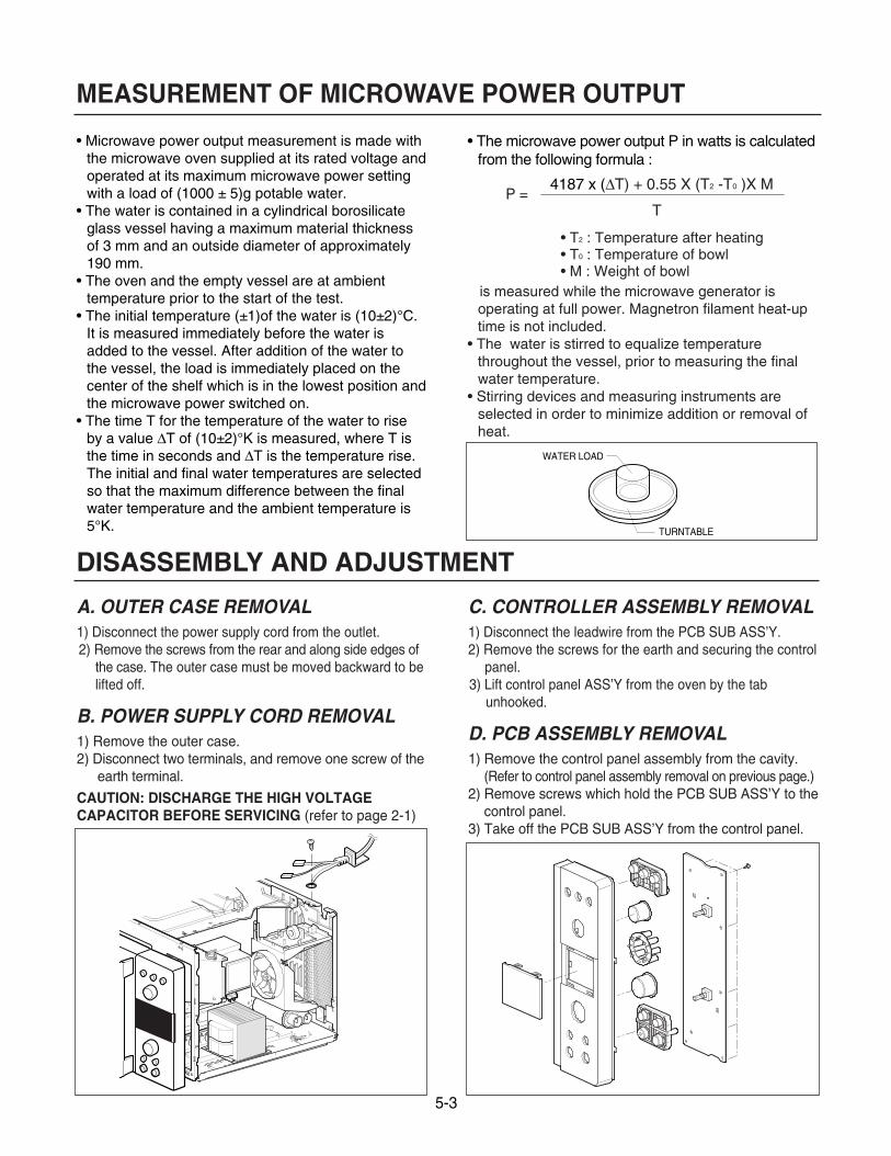
• Microwave power output measurement is made withthe microwave oven supplied at its rated voltage andoperated at its maximum microwave power settingwith a load of (1000 ± 5)g potable water.
• The water is contained in a cylindrical borosilicateglass vessel having a maximum material thicknessof 3 mm and an outside diameter of approximately190 mm.
• The oven and the empty vessel are at ambienttemperature prior to the start of the test.
• The initial temperature (±1)of the water is (10±2)°C.It is measured immediately before the water isadded to the vessel. After addition of the water tothe vessel, the load is immediately placed on thecenter of the shelf which is in the lowest position andthe microwave power switched on.
• The time T for the temperature of the water to riseby a value ∆T of (10±2)°K is measured, where T isthe time in seconds and ∆T is the temperature rise.The initial and final water temperatures are selectedso that the maximum difference between the finalwater temperature and the ambient temperature is 5°K.
• The microwave power output P in watts is calculatedfrom the following formula :
4187 x (∆T) + 0.55 X (T2 -T0 )X M
T
• T2 : Temperature after heating• T0 : Temperature of bowl• M : Weight of bowl
is measured while the microwave generator isoperating at full power. Magnetron filament heat-uptime is not included.
• The water is stirred to equalize temperaturethroughout the vessel, prior to measuring the finalwater temperature.
• Stirring devices and measuring instruments areselected in order to minimize addition or removal ofheat.
WATER LOAD
TURNTABLE
MEASUREMENT OF MICROWAVE POWER OUTPUT
P =
DISASSEMBLY AND ADJUSTMENT
A. OUTER CASE REMOVAL1) Disconnect the power supply cord from the outlet.2) Remove the screws from the rear and along side edges of
the case. The outer case must be moved backward to belifted off.
B. POWER SUPPLY CORD REMOVAL1) Remove the outer case.2) Disconnect two terminals, and remove one screw of the
earth terminal.
CAUTION: DISCHARGE THE HIGH VOLTAGE CAPACITOR BEFORE SERVICING (refer to page 2-1)
C. CONTROLLER ASSEMBLY REMOVAL1) Disconnect the leadwire from the PCB SUB ASS’Y.2) Remove the screws for the earth and securing the control
panel.3) Lift control panel ASS’Y from the oven by the tab
unhooked.
D. PCB ASSEMBLY REMOVAL1) Remove the control panel assembly from the cavity.
(Refer to control panel assembly removal on previous page.)2) Remove screws which hold the PCB SUB ASS’Y to the
control panel.3) Take off the PCB SUB ASS’Y from the control panel.
5-4
E. DOOR GROSS ASSEMBLY REMOVAL1) Open the door.2) Remove the choke cover very carefully with a
flat-blade screwdriver.CAUTION: Be careful not to damage door seal
plate by screwdriver.3) Lift up and push the door.
NOTE:1. After replacing the door, be sure to check that the
primary switch, monitor switch, and secondaryswitch operate normally.
2. After replacing the door, check for microwaveenergy leakage with a survey meter. Microwaveenergy must be below the limit of 5 mW/cm. (with a275 ml water load)
3. When mounting the door assembly to the ovenassembly, be sure to adjust the door assemblyparallel to the chassis. Also adjust so the door hasno play between the inner door surface and ovenframe assembly. If the door assembly is notmounted properly, microwaves may leak from theclearance between the door and the oven.
F. AIR DUCT ASSEMBLY REMOVAL1) Disconnect the leadwire from lamp and MGT
thermostat.2) Remove the mounting screw to the magnetron.
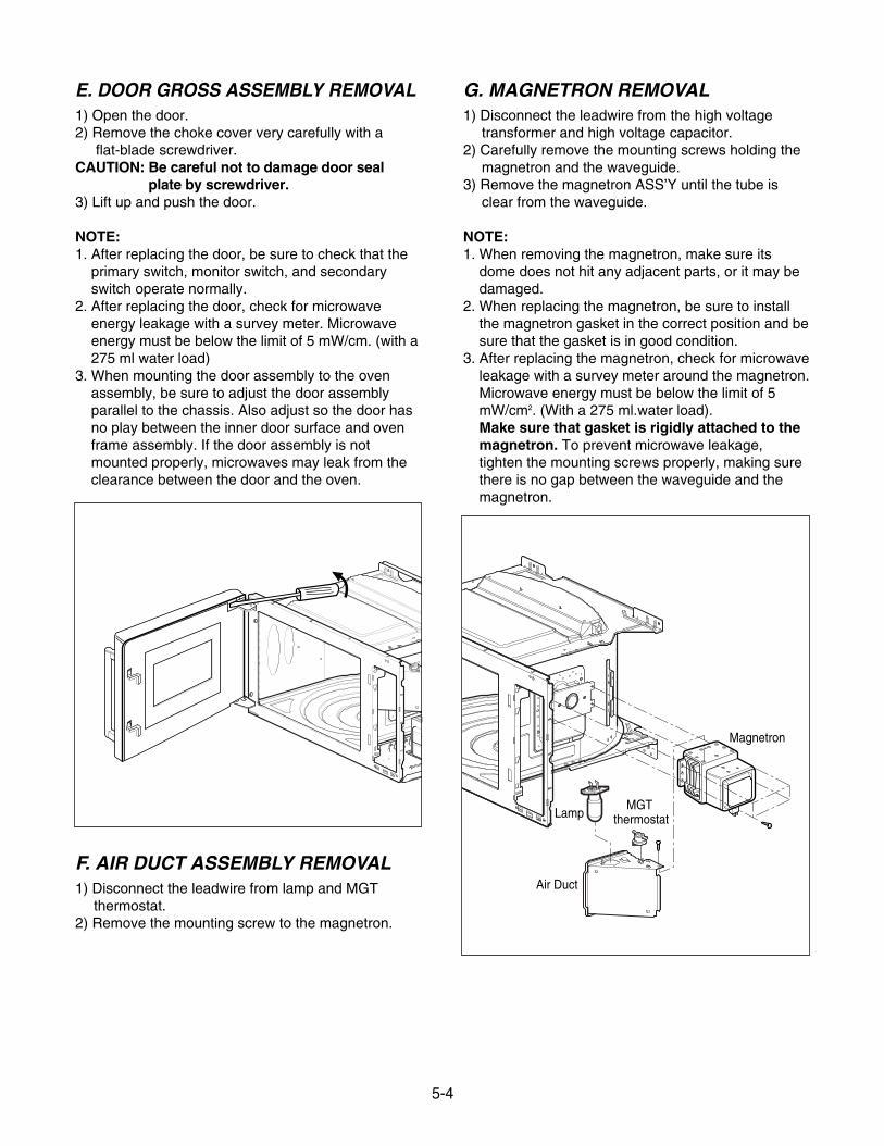
G. MAGNETRON REMOVAL1) Disconnect the leadwire from the high voltage
transformer and high voltage capacitor.2) Carefully remove the mounting screws holding the
magnetron and the waveguide.3) Remove the magnetron ASS’Y until the tube is
clear from the waveguide.
NOTE:1. When removing the magnetron, make sure its
dome does not hit any adjacent parts, or it may bedamaged.
2. When replacing the magnetron, be sure to installthe magnetron gasket in the correct position and besure that the gasket is in good condition.
3. After replacing the magnetron, check for microwaveleakage with a survey meter around the magnetron.Microwave energy must be below the limit of 5mW/cm2. (With a 275 ml.water load).Make sure that gasket is rigidly attached to themagnetron. To prevent microwave leakage,tighten the mounting screws properly, making surethere is no gap between the waveguide and themagnetron.
Magnetron
Air Duct
LampMGT
thermostat
5-5
H. FAN MOTOR ASSEMBLY REMOVAL1) Discharge the high voltage capacitor.2) Disconnect the leadwire from fan motor, noise filter
and high voltage capacitor.3) Remove the two screws holding the the suction guide
ASS’Y to the oven cavity and remove the high voltagediode earth screw.
4) Remove the screw of the capacitor bracket.5) Remove the two screws holding the fan motor ASS’Y
to the suction guide ASS’Y.
I. HIGH VOLTAGE CAPACITOR ANDDIODE REMOVAL
1) Discharge the high voltage capacitor.2) Disconnect the leadwire from fan motor, noise filter
and high voltage capacitor.3) Remove the screw holding the suction guide ASS’Y to
the oven cavity and remove the high voltage diodeearth screw.
4) Remove the screw holding the high voltage capacitorbracket.
J. HIGH VOLTAGE TRANSFORMER REMOVAL
1) Discharge the high voltage capacitor.2) Disconnect the leadwire from magnetron, high voltage
transformer, and capacitor.3) Remove the screw holding the high voltage
transformer to the baseplate.
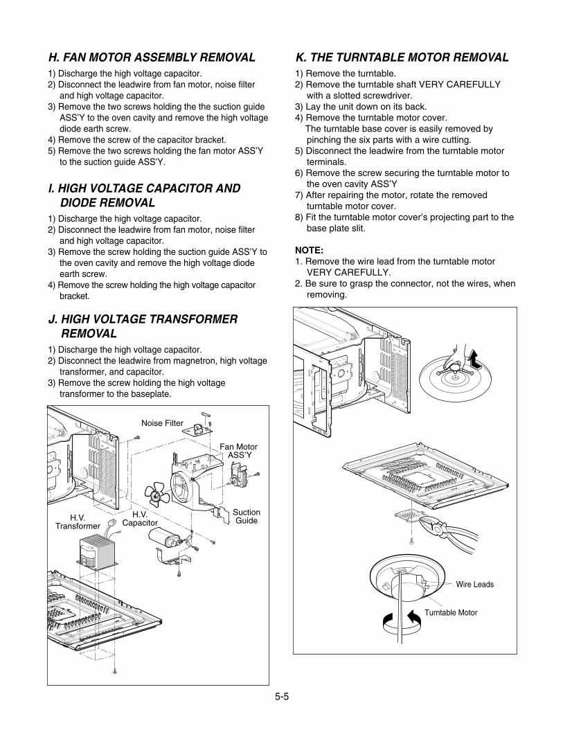
K. THE TURNTABLE MOTOR REMOVAL1) Remove the turntable.2) Remove the turntable shaft VERY CAREFULLY
with a slotted screwdriver.3) Lay the unit down on its back.4) Remove the turntable motor cover.
The turntable base cover is easily removed bypinching the six parts with a wire cutting.
5) Disconnect the leadwire from the turntable motorterminals.
6) Remove the screw securing the turntable motor tothe oven cavity ASS’Y
7) After repairing the motor, rotate the removedturntable motor cover.
8) Fit the turntable motor cover’s projecting part to thebase plate slit.
NOTE:1. Remove the wire lead from the turntable motor
VERY CAREFULLY.2. Be sure to grasp the connector, not the wires, when
removing.
SuctionGuide
Noise Filter
H.V.Capacitor
H.V.Transformer
Wire Leads
Turntable Motor
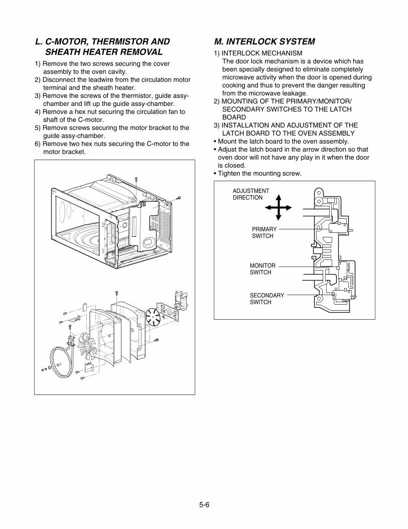
L. C-MOTOR, THERMISTOR ANDSHEATH HEATER REMOVAL
1) Remove the two screws securing the coverassembly to the oven cavity.
2) Disconnect the leadwire from the circulation motorterminal and the sheath heater.
3) Remove the screws of the thermistor, guide assy-chamber and lift up the guide assy-chamber.
4) Remove a hex nut securing the circulation fan toshaft of the C-motor.
5) Remove screws securing the motor bracket to theguide assy-chamber.
6) Remove two hex nuts securing the C-motor to themotor bracket.
M. INTERLOCK SYSTEM1) INTERLOCK MECHANISM
The door lock mechanism is a device which hasbeen specially designed to eliminate completelymicrowave activity when the door is opened duringcooking and thus to prevent the danger resultingfrom the microwave leakage.
2) MOUNTING OF THE PRIMARY/MONITOR/SECONDARY SWITCHES TO THE LATCHBOARD
3) INSTALLATION AND ADJUSTMENT OF THELATCH BOARD TO THE OVEN ASSEMBLY
• Mount the latch board to the oven assembly.• Adjust the latch board in the arrow direction so that
oven door will not have any play in it when the dooris closed.
• Tighten the mounting screw.
5-6
PRIMARYSWITCH
ADJUSTMENTDIRECTION
MONITORSWITCH
SECONDARYSWITCH
A. PRIMARY INTERLOCK SWITCH TESTWhen the door release button is depressed slowlywith the door closed, an audible click should beheard at the same time or successively atintervals. When the button is released slowly, thelatches should activate the switches with anaudible click.If the latches do not activate the switches whenthe door is closed, the switches should be aadjusted in accordance with the adjustmentprocedure. Disconnect the wire lead from theprimary switch. Connect the ohmmeter leads tothe common (COM) and normally open (NO)terminal of the switch. The meter should indicatean open circuit in the door open condition.When the door is closed, the meter shouldindicate a closed circuit.When the primary switch operation is abnormal,make the necessary adjustment or replace theswitch only with the same type of switch.
B. SECONDARY INTERLOCK SWITCH TESTDisconnect the wire lead from the secondaryswitch.Connect the ohmmeter leads to the common(COM) and normally open (NO) terminals of theswitch. The meter should indicate a open circuit inthe door open condition. When the door is closed,meter should indicate an closed circuit. When thesecondary switch operation is abnormal, make the necessary adjustment or replace the switchonly with the same type of switch.
C. MONITOR SWITCH TESTDisconnect the wire lead from the monitor switch.Connect the ohmmeter leads to the common(COM) and normally closed (NC) terminals of theswitch. The meter should indicate closed circuit inthe door open condition. When the door is closed,meter should indicate an open circuit. When themonitor switch operation is abnormal, replace withthe same type of switch.NOTE: After repairing the door or the interlocksystem, it is necessary to do this continuitytest before operating the oven.
5-7
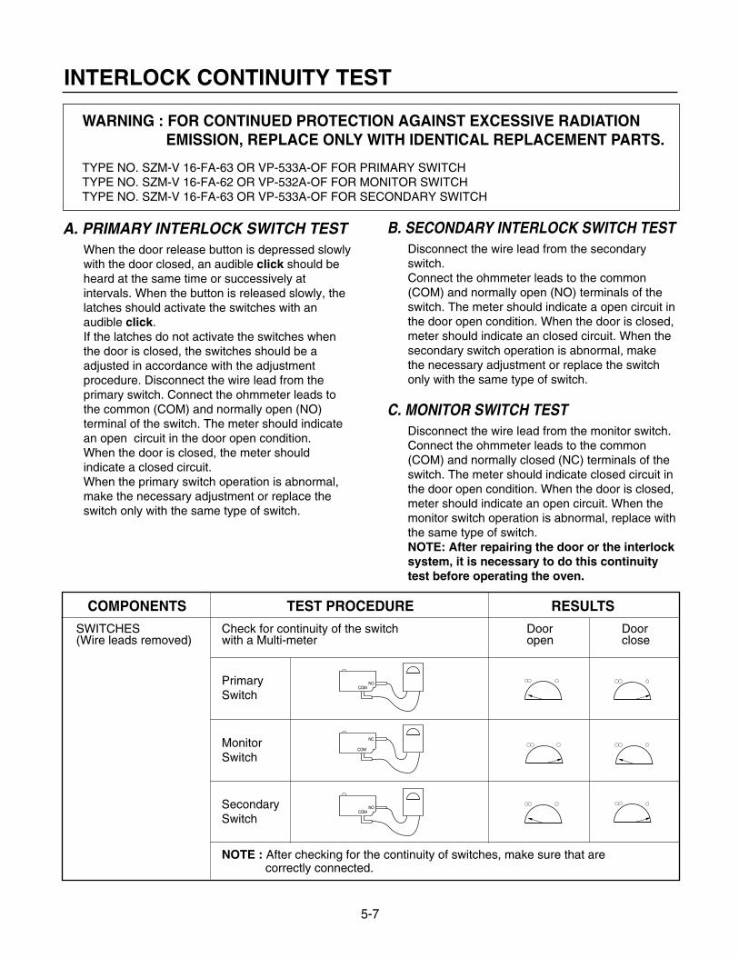
WARNING : FOR CONTINUED PROTECTION AGAINST EXCESSIVE RADIATION EMISSION, REPLACE ONLY WITH IDENTICAL REPLACEMENT PARTS.
TYPE NO. SZM-V 16-FA-63 OR VP-533A-OF FOR PRIMARY SWITCHTYPE NO. SZM-V 16-FA-62 OR VP-532A-OF FOR MONITOR SWITCHTYPE NO. SZM-V 16-FA-63 OR VP-533A-OF FOR SECONDARY SWITCH
COMPONENTS TEST PROCEDURE RESULTS
SWITCHES Check for continuity of the switch Door Door(Wire leads removed) with a Multi-meter open close
PrimarySwitch
MonitorSwitch
NOTE : After checking for the continuity of switches, make sure that arecorrectly connected.
COMNO
COMNO
NC
COM
INTERLOCK CONTINUITY TEST
SecondarySwitch
5-8
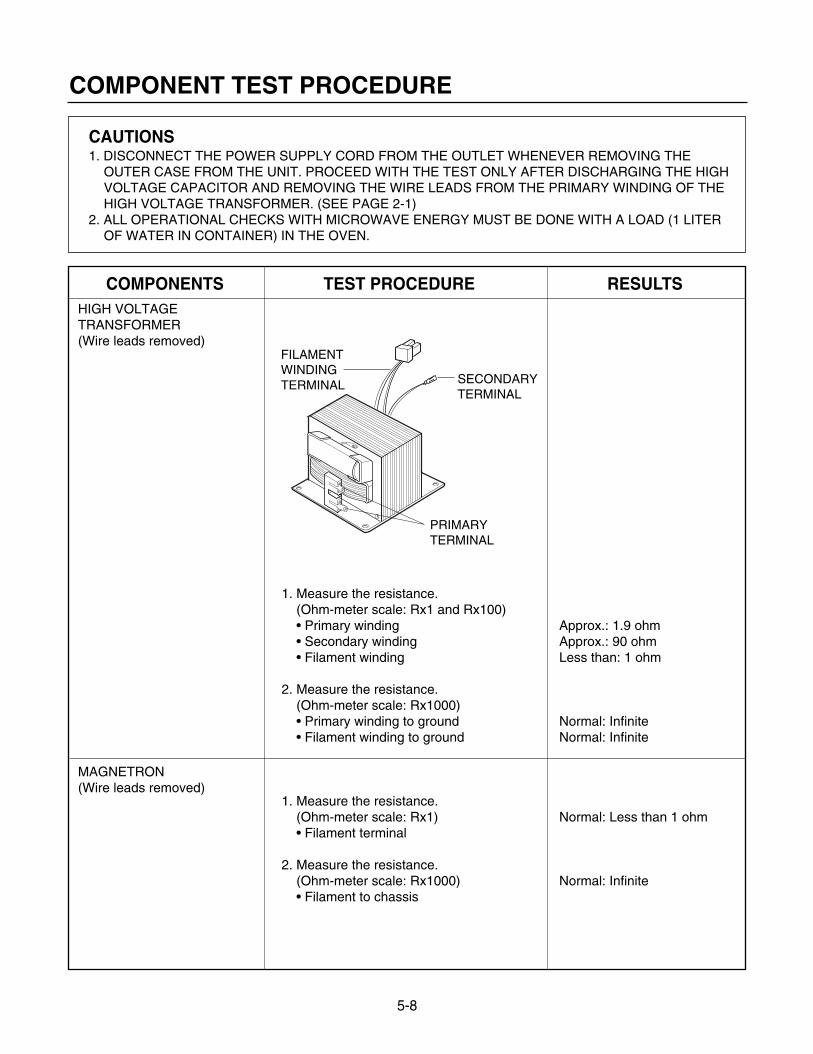
CAUTIONS1. DISCONNECT THE POWER SUPPLY CORD FROM THE OUTLET WHENEVER REMOVING THE
OUTER CASE FROM THE UNIT. PROCEED WITH THE TEST ONLY AFTER DISCHARGING THE HIGHVOLTAGE CAPACITOR AND REMOVING THE WIRE LEADS FROM THE PRIMARY WINDING OF THEHIGH VOLTAGE TRANSFORMER. (SEE PAGE 2-1)
2. ALL OPERATIONAL CHECKS WITH MICROWAVE ENERGY MUST BE DONE WITH A LOAD (1 LITEROF WATER IN CONTAINER) IN THE OVEN.
COMPONENTS TEST PROCEDURE RESULTSHIGH VOLTAGETRANSFORMER(Wire leads removed)
MAGNETRON(Wire leads removed)
1. Measure the resistance.(Ohm-meter scale: Rx1 and Rx100)• Primary winding• Secondary winding• Filament winding
2. Measure the resistance.(Ohm-meter scale: Rx1000)• Primary winding to ground• Filament winding to ground
1. Measure the resistance.(Ohm-meter scale: Rx1)• Filament terminal
2. Measure the resistance.(Ohm-meter scale: Rx1000)• Filament to chassis
Approx.: 1.9 ohmApprox.: 90 ohmLess than: 1 ohm
Normal: InfiniteNormal: Infinite
Normal: Less than 1 ohm
Normal: Infinite
FILAMENT WINDINGTERMINAL
PRIMARY TERMINAL
SECONDARY TERMINAL
COMPONENT TEST PROCEDURE
5-9
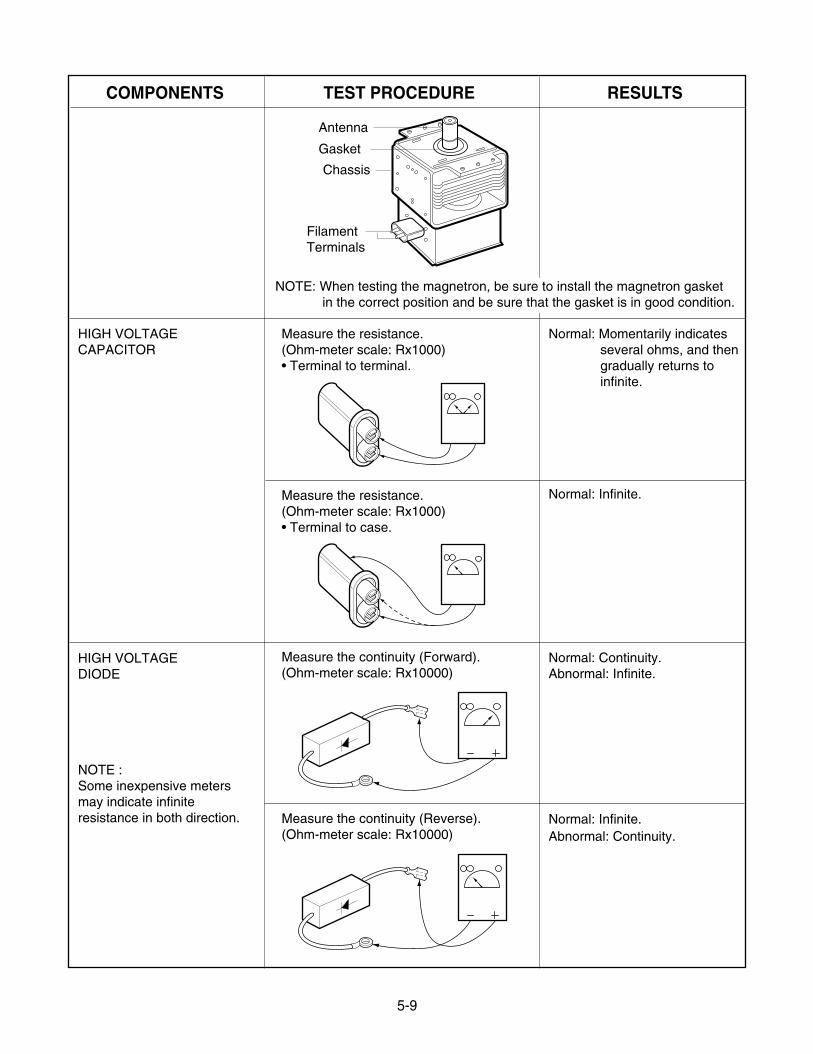
COMPONENTS TEST PROCEDURE RESULTS
HIGH VOLTAGECAPACITOR
HIGH VOLTAGEDIODE
NOTE :Some inexpensive metersmay indicate infiniteresistance in both direction.
Measure the resistance.(Ohm-meter scale: Rx1000)• Terminal to terminal.
Measure the resistance.(Ohm-meter scale: Rx1000)• Terminal to case.
Measure the continuity (Forward).(Ohm-meter scale: Rx10000)
Measure the continuity (Reverse).(Ohm-meter scale: Rx10000)
Normal: Momentarily indicatesseveral ohms, and thengradually returns to infinite.
Normal: Infinite.
Normal: Continuity.Abnormal: Infinite.
Normal: Infinite.Abnormal: Continuity.
NOTE: When testing the magnetron, be sure to install the magnetron gasketin the correct position and be sure that the gasket is in good condition.
Antenna
Gasket
Chassis
FilamentTerminals
5-10
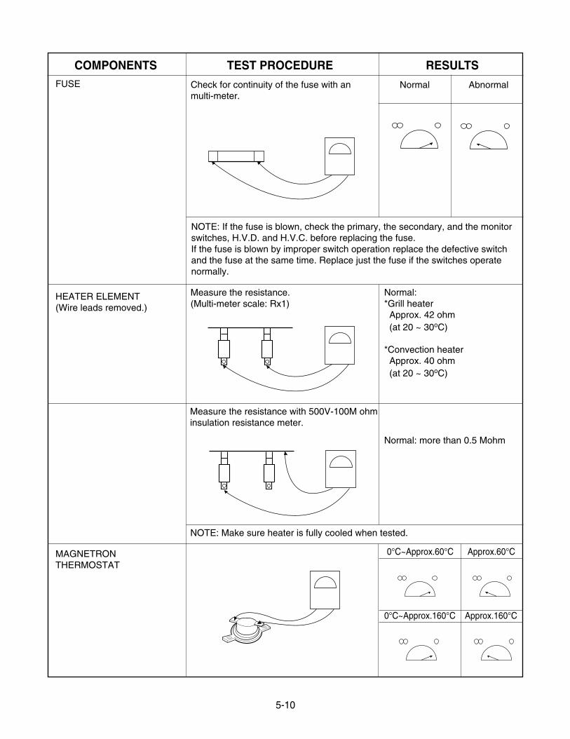
COMPONENTS TEST PROCEDURE RESULTSFUSE
HEATER ELEMENT(Wire leads removed.)
MAGNETRONTHERMOSTAT
Check for continuity of the fuse with anmulti-meter.
NOTE: If the fuse is blown, check the primary, the secondary, and the monitorswitches, H.V.D. and H.V.C. before replacing the fuse.If the fuse is blown by improper switch operation replace the defective switchand the fuse at the same time. Replace just the fuse if the switches operatenormally.
NOTE: Make sure heater is fully cooled when tested.
Measure the resistance.(Multi-meter scale: Rx1)
Normal:*Grill heaterApprox. 42 ohm(at 20 ~ 30oC)
*Convection heaterApprox. 40 ohm(at 20 ~ 30oC)
Normal: more than 0.5 Mohm
Normal Abnormal
Measure the resistance with 500V-100M ohminsulation resistance meter.
0°C~Approx.60°C Approx.60°C
0°C~Approx.160°C Approx.160°C
5-11
COMPONENTS TEST PROCEDURE RESULTS
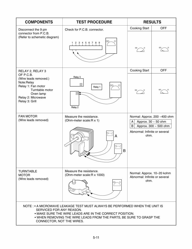
Disconnect the 9 pinconnector from P.C.B.(Refer to schemetic diagram)
RELAY 2, RELAY 3OF P.C.B.(Wire leads removed.)Note:RelayRelay 1: Fan motor
Turntable motorOven lamp
Relay 2: MicrowaveRelay 3: Grill
FAN MOTOR(Wire leads removed)
TURNTABLEMOTOR(Wire leads removed)
Measure the resistance.(Ohm-meter scale:R x 1)
Measure the resistance.(Ohm-meter scale:R x 1000)
Check for P.C.B. connector.
Normal: Approx. 200 ~400 ohm
Abnormal: Infinite or several ohm.
Normal: Approx. 10~20 kohmAbnormal: Infinite or several
ohm.
NOTE : • A MICROWAVE LEAKAGE TEST MUST ALWAYS BE PERFORMED WHEN THE UNIT ISSERVICED FOR ANY REASON.
• MAKE SURE THE WIRE LEADS ARE IN THE CORRECT POSITION.• WHEN REMOVING THE WIRE LEADS FROM THE PARTS, BE SURE TO GRASP THECONNECTOR, NOT THE WIRES.
A
B
Cooking Start OFF
Relay 2
Relay 1
Relay 3
1 2 3 4 5 6 7 8 9
Cooking Start OFF
A Approx. 30 ~ 50 ohmB Approx. 300 ~ 500 ohm
5-12
COMPONENTS TEST PROCEDURE RESULTS
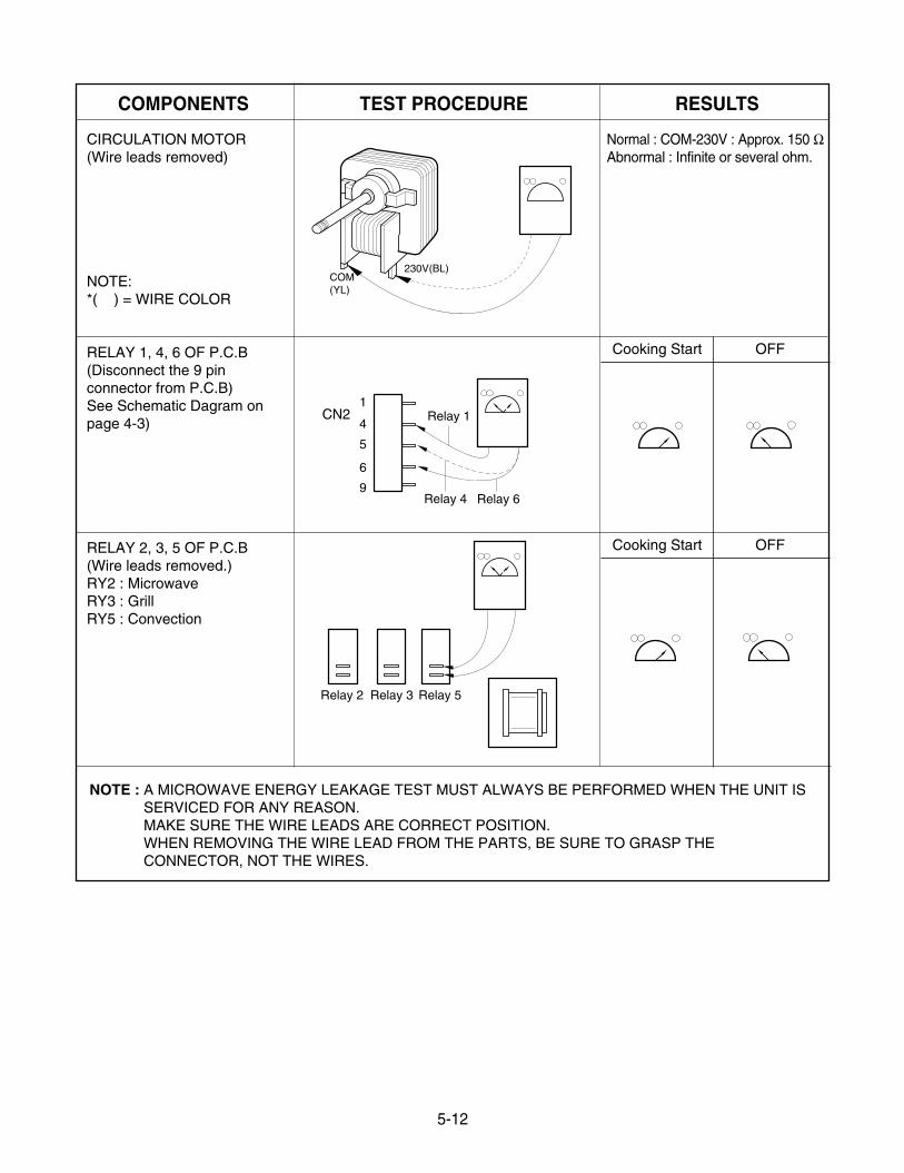
CIRCULATION MOTOR(Wire leads removed)
NOTE:*( ) = WIRE COLOR
RELAY 1, 4, 6 OF P.C.B(Disconnect the 9 pinconnector from P.C.B)See Schematic Dagram onpage 4-3)
RELAY 2, 3, 5 OF P.C.B(Wire leads removed.)RY2 : MicrowaveRY3 : GrillRY5 : Convection
NOTE : A MICROWAVE ENERGY LEAKAGE TEST MUST ALWAYS BE PERFORMED WHEN THE UNIT ISSERVICED FOR ANY REASON.MAKE SURE THE WIRE LEADS ARE CORRECT POSITION.WHEN REMOVING THE WIRE LEAD FROM THE PARTS, BE SURE TO GRASP THECONNECTOR, NOT THE WIRES.
Cooking Start OFF
COM(YL)
230V(BL)
CN21
4
5
6
9Relay 4
Relay 1
Relay 6
Relay 2 Relay 3 Relay 5
Cooking Start OFF
Normal : COM-230V : Approx. 150 ΩAbnormal : Infinite or several ohm.
5-13
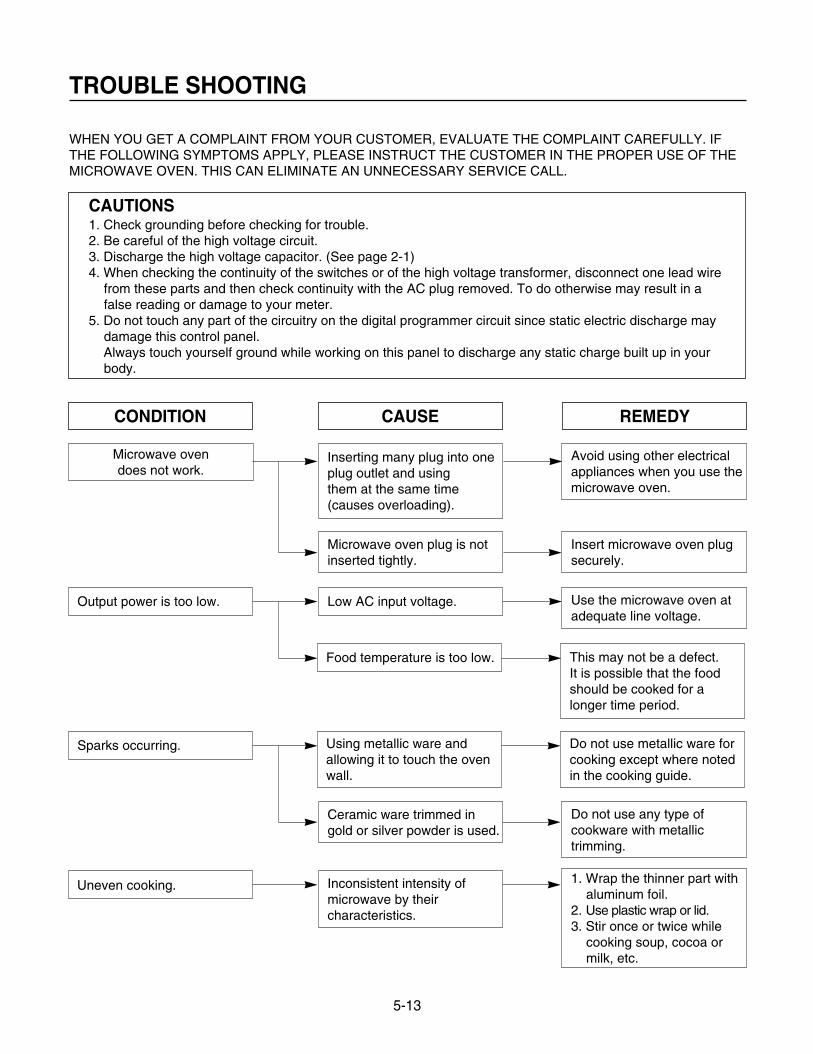
TROUBLE SHOOTING
WHEN YOU GET A COMPLAINT FROM YOUR CUSTOMER, EVALUATE THE COMPLAINT CAREFULLY. IFTHE FOLLOWING SYMPTOMS APPLY, PLEASE INSTRUCT THE CUSTOMER IN THE PROPER USE OF THEMICROWAVE OVEN. THIS CAN ELIMINATE AN UNNECESSARY SERVICE CALL.
CAUTIONS1. Check grounding before checking for trouble.2. Be careful of the high voltage circuit.3. Discharge the high voltage capacitor. (See page 2-1)4. When checking the continuity of the switches or of the high voltage transformer, disconnect one lead wire
from these parts and then check continuity with the AC plug removed. To do otherwise may result in afalse reading or damage to your meter.
5. Do not touch any part of the circuitry on the digital programmer circuit since static electric discharge maydamage this control panel.Always touch yourself ground while working on this panel to discharge any static charge built up in yourbody.
CONDITION
Microwave oven does not work.
Inserting many plug into oneplug outlet and using them at the same time (causes overloading).
Microwave oven plug is notinserted tightly.
Output power is too low. Low AC input voltage.
Food temperature is too low.
Using metallic ware andallowing it to touch the ovenwall.
Sparks occurring.
Inconsistent intensity ofmicrowave by theircharacteristics.
1. Wrap the thinner part withaluminum foil.
2. Use plastic wrap or lid.3. Stir once or twice while
cooking soup, cocoa ormilk, etc.
Uneven cooking.
Ceramic ware trimmed ingold or silver powder is used.
Avoid using other electricalappliances when you use themicrowave oven.
Insert microwave oven plugsecurely.
Use the microwave oven atadequate line voltage.
This may not be a defect.It is possible that the foodshould be cooked for alonger time period.
Do not use metallic ware forcooking except where notedin the cooking guide.
Do not use any type ofcookware with metallictrimming.
CAUSE REMEDY
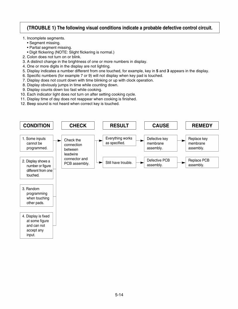
1. Incomplete segments.• Segment missing.• Partial segment missing.• Digit flickering (NOTE: Slight flickering is normal.)
2. Colon does not turn on or blink.3. A distinct change in the brightness of one or more numbers in display.4. One or more digits in the display are not lighting.5. Display indicates a number different from one touched, for example, key in 5 and 3 appears in the display.6. Specific numbers (for example 7 or 9) will not display when key pad is touched.7. Display does not count down with time blinking or up with clock operation.8. Display obviously jumps in time while counting down.9. Display counts down too fast while cooking.
10. Each indicator light does not turn on after setting cooking cycle.11. Display time of day does not reappear when cooking is finished.12. Beep sound is not heard when correct key is touched.
5-14
(TROUBLE 1) The following visual conditions indicate a probable defective control circuit.
CONDITION CHECK RESULT CAUSE REMEDY
Everything worksas specified.
Still have trouble.
Defective keymembraneassembly.
Defective PCBassembly.
Replace keymembraneassembly.
Replace PCBassembly.
Check theconnectionbetweenleadwireconnector andPCB assembly.
1. Some inputscannot beprogrammed.
2. Display shows anumber or figuredifferent from onetouched.
3. Randomprogrammingwhen touchingother pads.
4. Display is fixedat some figureand can notaccept anyinput.
5-15
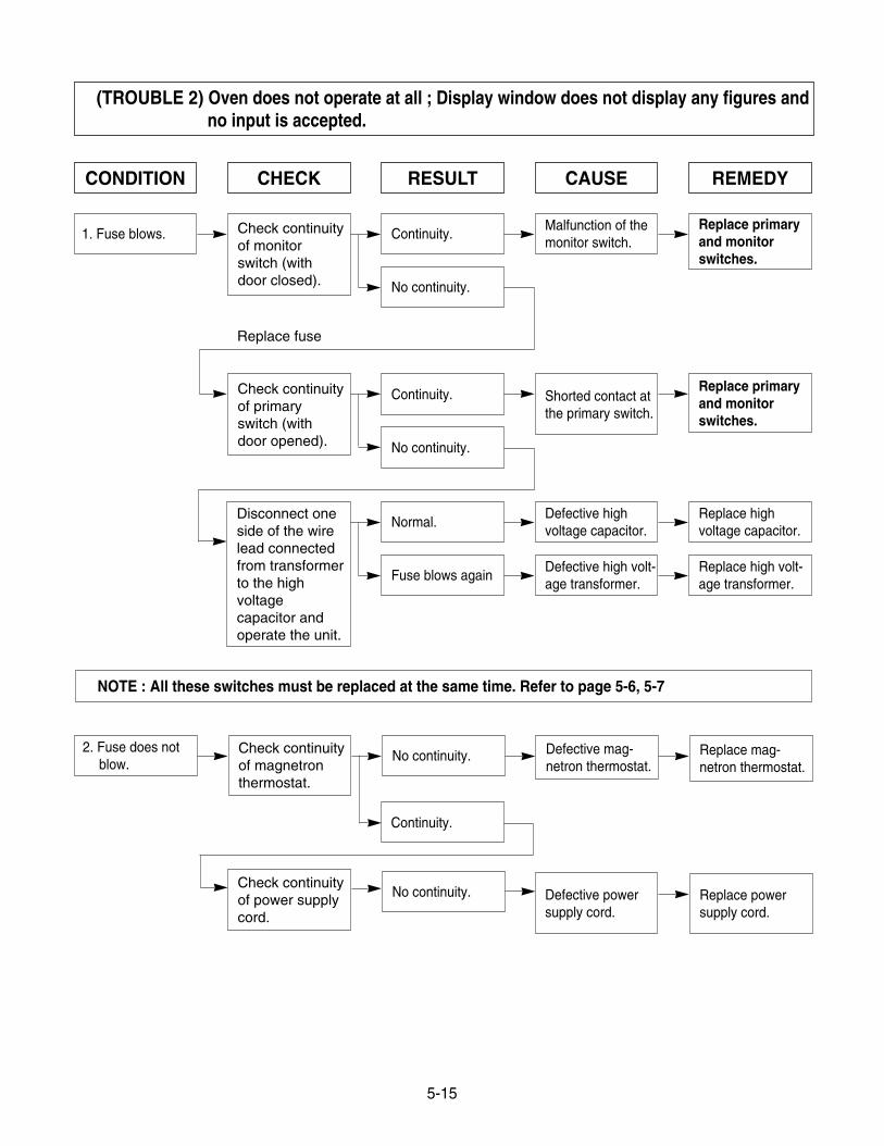
CONDITION CHECK RESULT CAUSE REMEDY
1. Fuse blows. Continuity.
No continuity.
Continuity. Shorted contact atthe primary switch.
Replace primaryand monitorswitches.
No continuity.
Normal.Defective highvoltage capacitor.
Replace highvoltage capacitor.
Fuse blows againDefective high volt-age transformer.
Replace high volt-age transformer.
Malfunction of themonitor switch.
Replace primaryand monitorswitches.
Check continuityof monitorswitch (withdoor closed).
Check continuityof primaryswitch (withdoor opened).
Disconnect oneside of the wirelead connectedfrom transformerto the highvoltagecapacitor andoperate the unit.
Replace fuse
(TROUBLE 2) Oven does not operate at all ; Display window does not display any figures and no input is accepted.
NOTE : All these switches must be replaced at the same time. Refer to page 5-6, 5-7
2. Fuse does notblow.
No continuity.
No continuity. Replace powersupply cord.
Defective mag-netron thermostat.
Defective powersupply cord.
Replace mag-netron thermostat.
Check continuityof magnetronthermostat.
Check continuityof power supplycord.
Continuity.
5-16
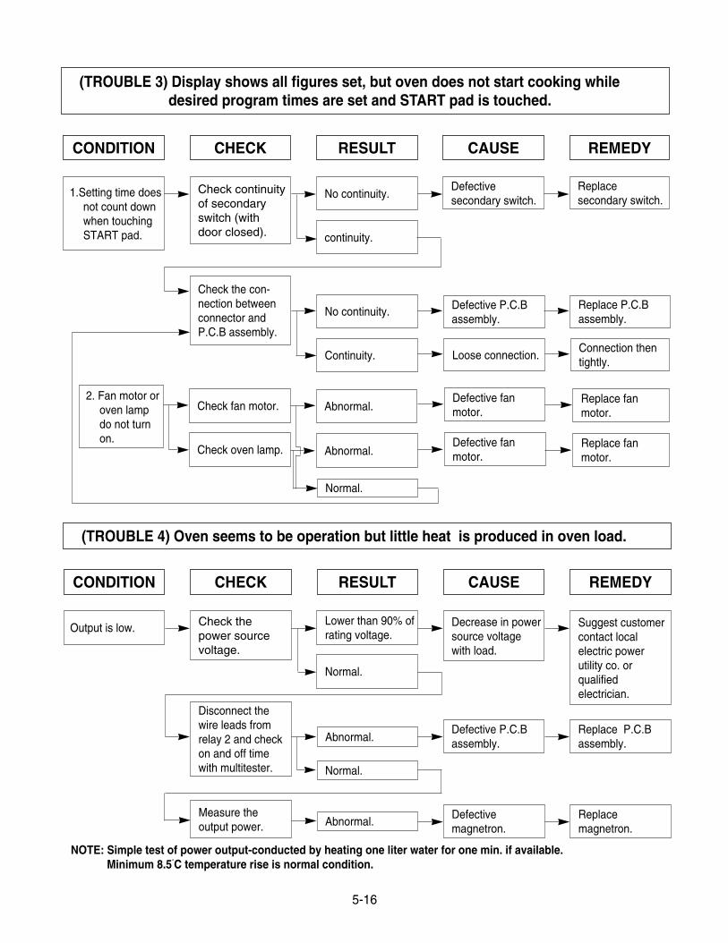
(TROUBLE 3) Display shows all figures set, but oven does not start cooking while desired program times are set and START pad is touched.
(TROUBLE 4) Oven seems to be operation but little heat is produced in oven load.
CONDITION CHECK RESULT CAUSE REMEDY
1.Setting time doesnot count downwhen touchingSTART pad.
2. Fan motor oroven lampdo not turnon.
No continuity.
continuity.
No continuity.
Continuity.
Check the con-nection betweenconnector andP.C.B assembly.
Defectivesecondary switch.
Replacesecondary switch.
Defective P.C.Bassembly.
Replace P.C.Bassembly.
Check continuityof secondaryswitch (withdoor closed).
Check fan motor.
Check oven lamp.
Abnormal.
Abnormal.
Normal.
Defective fanmotor.
Defective fanmotor.
Replace fanmotor.
Replace fanmotor.
Loose connection.Connection thentightly.
CONDITION CHECK RESULT CAUSE REMEDY
Output is low.Lower than 90% ofrating voltage.
Normal.
Normal.
Abnormal.
Abnormal.Measure theoutput power.
Disconnect thewire leads fromrelay 2 and checkon and off timewith multitester.
Defective P.C.Bassembly.
Replace P.C.Bassembly.
Decrease in powersource voltagewith load.
Suggest customercontact localelectric powerutility co. orqualifiedelectrician.
Check thepower sourcevoltage.
Defectivemagnetron.
Replacemagnetron.
NOTE: Simple test of power output-conducted by heating one liter water for one min. if available.Minimum 8.5˚C temperature rise is normal condition.
5-17
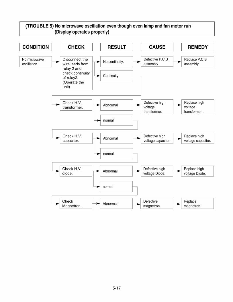
CONDITION CHECK RESULT CAUSE REMEDY
No microwaveoscillation.
No continuity.
Continuity.
Defective P.C.Bassembly
Replace P.C.Bassembly
Disconnect thewire leads fromrelay 2 andcheck continuityof relay2.(Operate theunit)
Abnormal
normal
Defective highvoltagetransformer.
Replace highvoltagetransformer .
Check H.V.transformer.
normal
normal
AbnormalDefective highvoltage Diode.
Replace highvoltage Diode.
Check H.V.diode.
AbnormalDefective highvoltage capacitor.
Replace highvoltage capacitor.
Check H.V.capacitor.
AbnormalDefectivemagnetron.
Replacemagnetron.
CheckMagnetron.
(TROUBLE 5) No microwave oscillation even though oven lamp and fan motor run(Display operates properly)
5-18
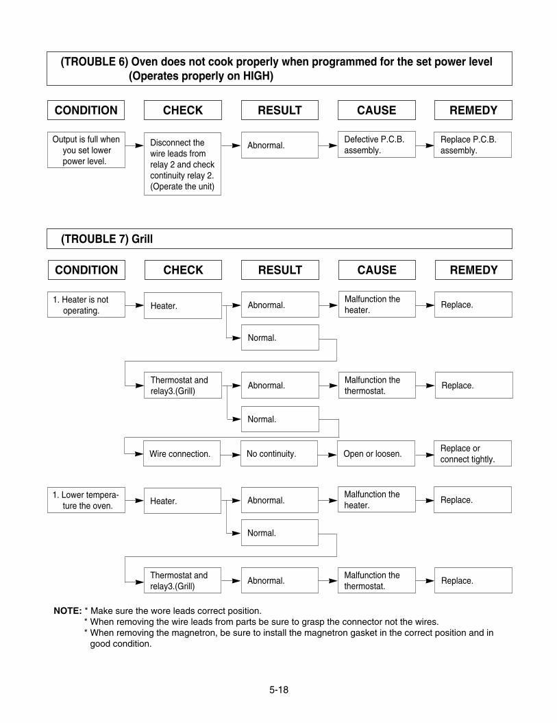
(TROUBLE 7) Grill
CONDITION CHECK RESULT CAUSE REMEDY
1. Heater is notoperating.
Abnormal.
Normal.
Normal.
Heater.
Thermostat andrelay3.(Grill)
Abnormal.Malfunction thethermostat.
Malfunction theheater.
Replace.
Wire connection. No continuity. Open or loosen.Replace orconnect tightly.
Replace.
1. Lower tempera-ture the oven.
Abnormal.
Normal.
Heater.
Thermostat andrelay3.(Grill)
Abnormal.Malfunction thethermostat.
Malfunction theheater.
Replace.
Replace.
(TROUBLE 6) Oven does not cook properly when programmed for the set power level (Operates properly on HIGH)
CONDITION CHECK RESULT CAUSE REMEDY
Output is full whenyou set lowerpower level.
Abnormal.Disconnect thewire leads fromrelay 2 and checkcontinuity relay 2.(Operate the unit)
Defective P.C.B.assembly.
Replace P.C.B.assembly.
NOTE: * Make sure the wore leads correct position.* When removing the wire leads from parts be sure to grasp the connector not the wires.* When removing the magnetron, be sure to install the magnetron gasket in the correct position and in
good condition.
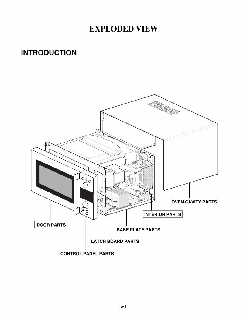
DOOR PARTS
CONTROL PANEL PARTS
INTERIOR PARTS
OVEN CAVITY PARTS
LATCH BOARD PARTS
BASE PLATE PARTS
6-1
EXPLODED VIEW
INTRODUCTION
6-2
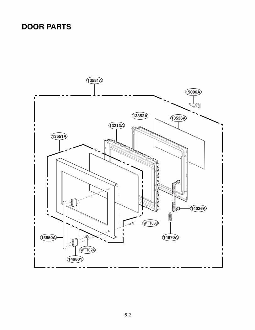
13352A 13536A
14026A
13213A
13581A
WTT030
WTT024
13551A
13650A
149801
15006A
14970A
DOOR PARTS
6-3
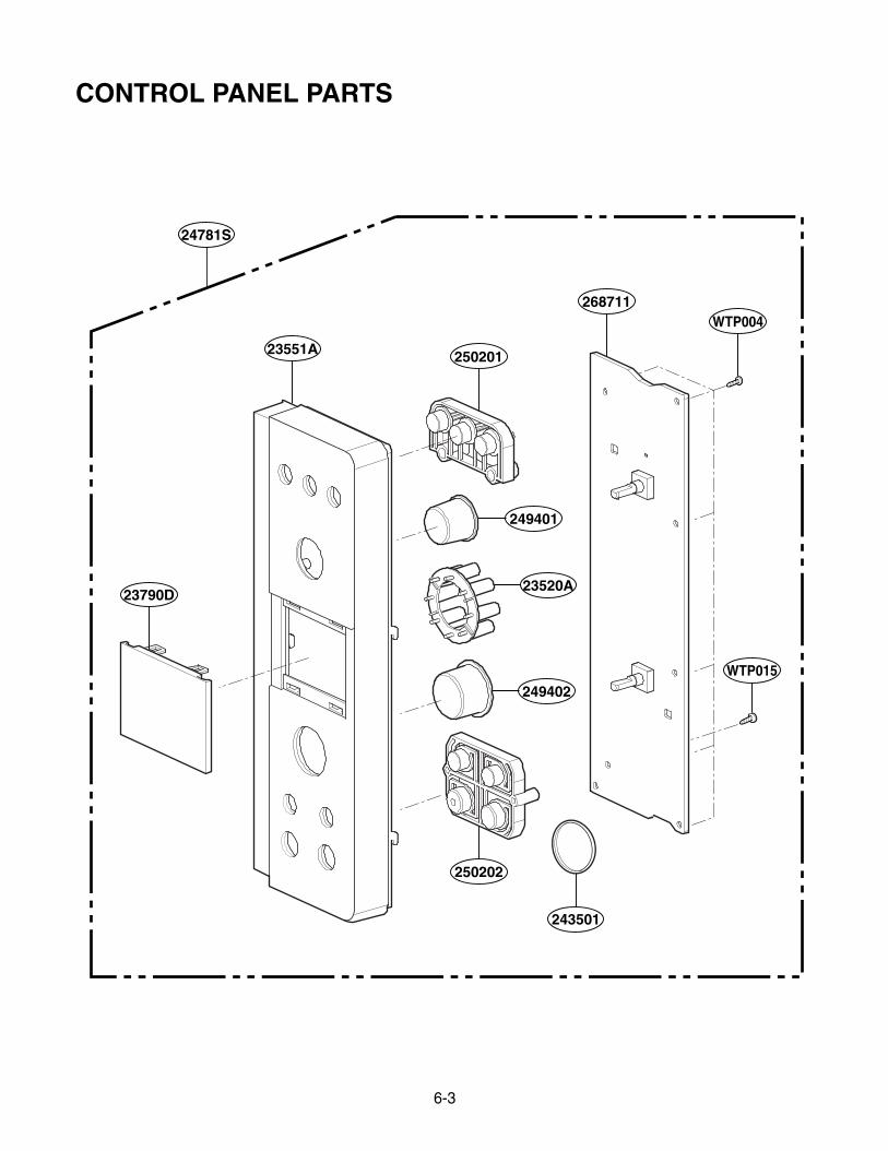
24781S
249401
23520A
249402
268711WTP004
WTP015
23551A 250201
23790D
250202
243501
CONTROL PANEL PARTS
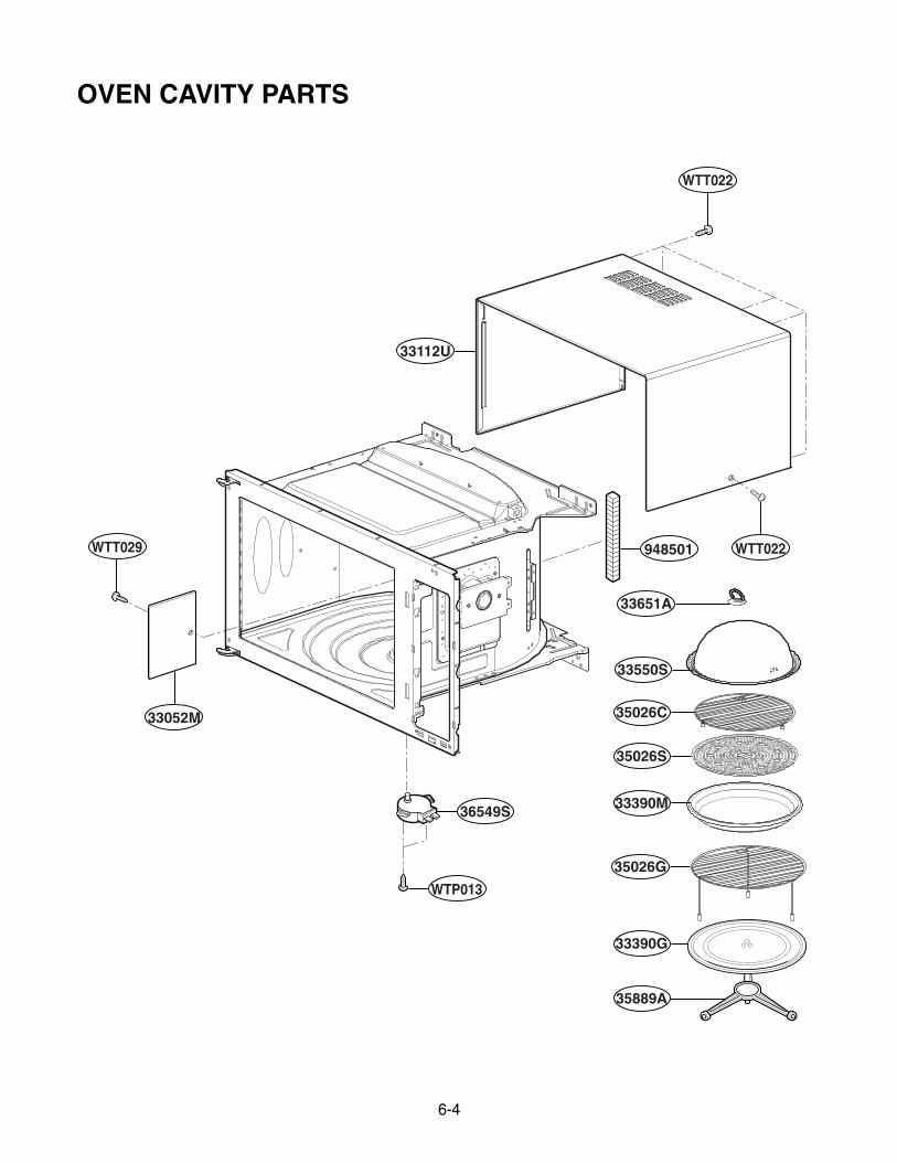
6-4
35026C
35026S
36549S
33052M
WTP013
WTT029
33112U
948501
WTT022
WTT022
33390M
35026G
33390G
35889A
33550S
33651A
OVEN CAVITY PARTS
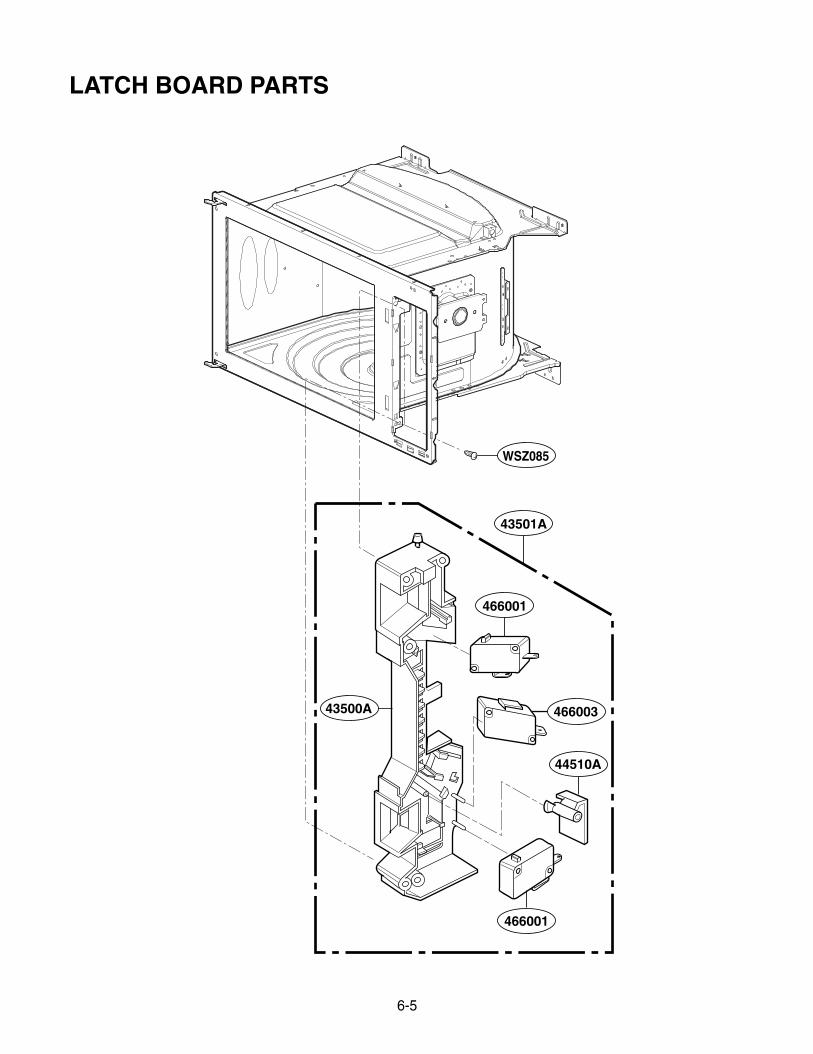
6-5
WSZ085
43501A
466001
43500A 466003
44510A
466001
LATCH BOARD PARTS
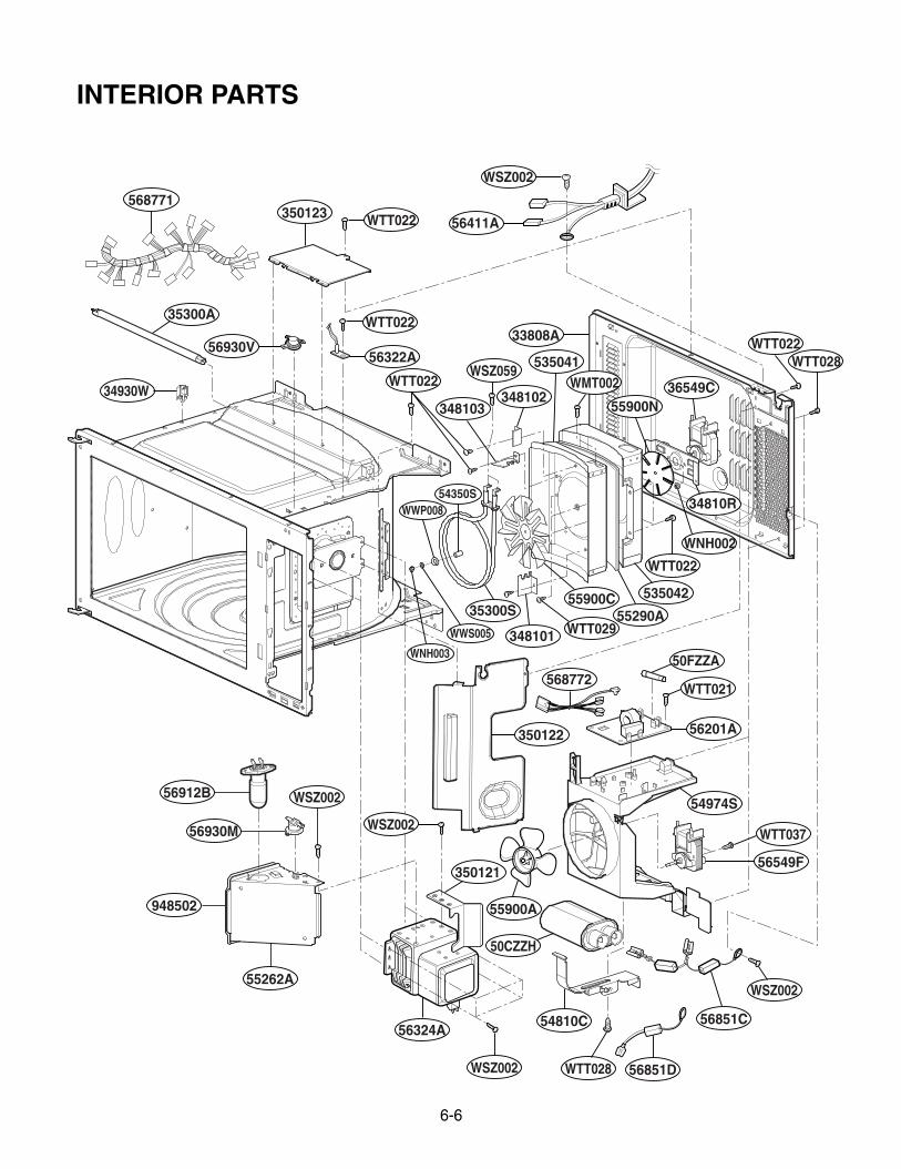
6-6
568771
56930V
34930W
35300A
WTT022
WTT022
WTT022
WTT022WTT028
350123
56322A
33808A
56411A
WSZ002
36549C
34810R
535042
50FZZA
56201A
54974S
WTT037
WSZ002
WTT028WSZ002
50CZZH
56549F
56851C
56851D
54810C56324A
55262A
948502
56930M
56912B
350122
55900A
350121
WTT021
WTT022
WNH002
55900N348103348102
535041WMT002
WTT029
54350SWWP008
WWS005
WNH003
WSZ059
55290A55900C
348101
568772
35300S
WSZ002
WSZ002
INTERIOR PARTS
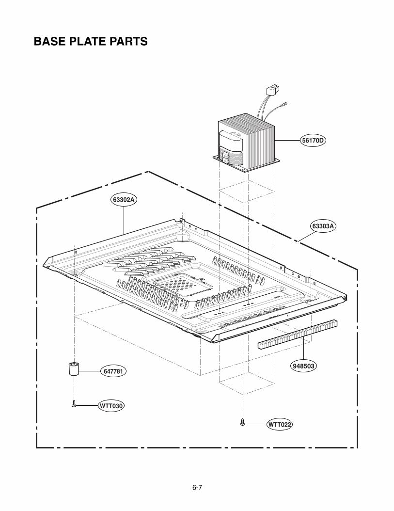
6-7
63302A
63303A
56170D
647781
WTT030
WTT022
948503
BASE PLATE PARTS