Embed Size (px)
Citation preview
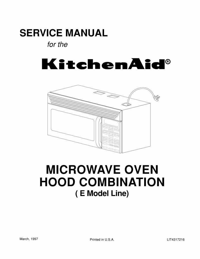
LIT4317216Printed in U.S.A.
SERVICE MANUAL for the
March, 1997
MICROWAVE OVENHOOD COMBINATION
( E Model Line)

ii
THIS MANUAL CONTAINS INFORMATION NECES-SARY FOR SERVICING THE KITCHENAID MICRO-WAVE OVEN HOOD COMBINATION , MODELS:
KHMS105EKHMC107E
THE MANUAL IS DESIGNED TO BE USED ONLY BYQUALIFIED SERVICE PERSONNEL. THE SERVICEINFORMATION IS ORGANIZED TO HELP YOU EAS-ILY FIND WHAT YOU NEED.
CHECK YOUR LOCAL BUILDING CODE FOR THEPROPER MODE OF INSTALLATION. IN THE AB-SENCE OF LOCAL CODES, THIS UNIT SHOULD BEINSTALLED IN ACCORDANCE WITH THE NATIONALELECTRICAL CODE, ANSI/NFPA NO. 70 - 1990, ORLATEST EDITION, OR C22.1 CANADIAN ELECTRI-CAL CODE, PART 1.
iii
Original 03/97
Page iiiMicrowave Oven Hood Combo Service Manual — LIT 4317216
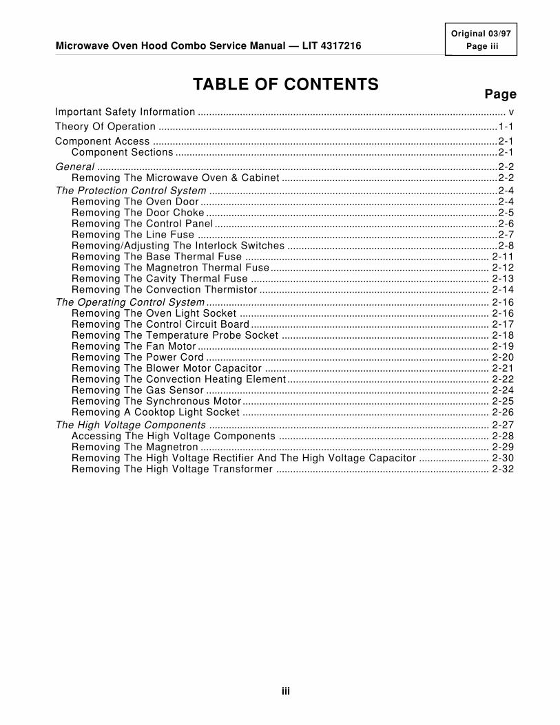
TABLE OF CONTENTSPage
Important Safety Information .............................................................................................................. v
Theory Of Operation .........................................................................................................................1-1
Component Access ...........................................................................................................................2-1Component Sections ...................................................................................................................2-1
General ...............................................................................................................................................2-2Removing The Microwave Oven & Cabinet .............................................................................2-2
The Protection Control System .......................................................................................................2-4Removing The Oven Door ..........................................................................................................2-4Removing The Door Choke ........................................................................................................2-5Removing The Control Panel .....................................................................................................2-6Removing The Line Fuse ...........................................................................................................2-7Removing/Adjusting The Interlock Switches ...........................................................................2-8Removing The Base Thermal Fuse ....................................................................................... 2-11Removing The Magnetron Thermal Fuse .............................................................................. 2-12Removing The Cavity Thermal Fuse ..................................................................................... 2-13Removing The Convection Thermistor .................................................................................. 2-14
The Operating Control System ..................................................................................................... 2-16Removing The Oven Light Socket ......................................................................................... 2-16Removing The Control Circuit Board ..................................................................................... 2-17Removing The Temperature Probe Socket .......................................................................... 2-18Removing The Fan Motor ........................................................................................................ 2-19Removing The Power Cord ..................................................................................................... 2-20Removing The Blower Motor Capacitor ................................................................................ 2-21Removing The Convection Heating Element ........................................................................ 2-22Removing The Gas Sensor ..................................................................................................... 2-24Removing The Synchronous Motor ........................................................................................ 2-25Removing A Cooktop Light Socket ........................................................................................ 2-26
The High Voltage Components .................................................................................................... 2-27Accessing The High Voltage Components ........................................................................... 2-28Removing The Magnetron ....................................................................................................... 2-29Removing The High Voltage Rectifier And The High Voltage Capacitor ......................... 2-30Removing The High Voltage Transformer ............................................................................ 2-32

iv
Page
Component Description & Testing ..................................................................................................3-1Important Safety Instructions .....................................................................................................3-1The Thermal Fuses .....................................................................................................................3-4The Blower Motor Capacitor ......................................................................................................3-5The Gas Sensor ...........................................................................................................................3-6The Convection Thermistor ........................................................................................................3-7The Convection Heating Element .............................................................................................3-8Motors ...........................................................................................................................................3-9Programming Checks ............................................................................................................... 3-10Things To Know ........................................................................................................................ 3-11Charts ......................................................................................................................................... 3-12Checking The Microwave Power Output ............................................................................... 3-15Checking For Microwave Energy Leakage ........................................................................... 3-16Component Testing .................................................................................................................. 3-19Control Circuit Board Checklist .............................................................................................. 3-24Primary, Monitor, & Secondary Switch Checkout Procedure............................................. 3-25
Tech Tips ............................................................................................................................................4-1Wiring Diagrams ..........................................................................................................................4-1Strip Circuits .................................................................................................................................4-3Specifications ...............................................................................................................................4-7Specification Charts ....................................................................................................................4-8Model & Serial Number Explanation ...................................................................................... 4-12KitchenAid Microwave Hood Warranty .................................................................................. 4-13
v
Original 03/97
Page vMicrowave Oven Hood Combo Service Manual — LIT 4317216
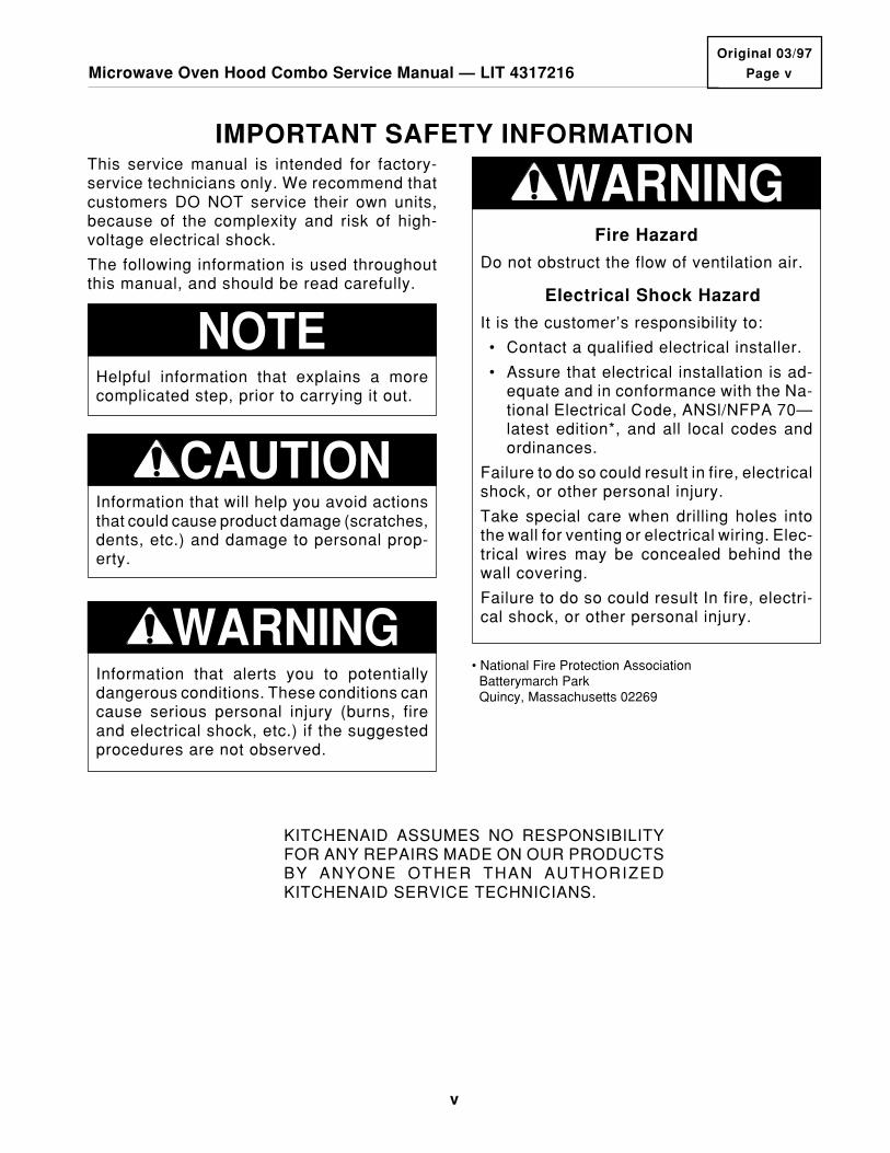
IMPORTANT SAFETY INFORMATION
KITCHENAID ASSUMES NO RESPONSIBILITYFOR ANY REPAIRS MADE ON OUR PRODUCTSBY ANYONE OTHER THAN AUTHORIZEDKITCHENAID SERVICE TECHNICIANS.
Fire Hazard
Do not obstruct the flow of ventilation air.
Electrical Shock Hazard
It is the customer’s responsibility to:
• Contact a qualified electrical installer.
• Assure that electrical installation is ad-equate and in conformance with the Na-tional Electrical Code, ANSl/NFPA 70—latest edition*, and all local codes andordinances.
Failure to do so could result in fire, electricalshock, or other personal injury.
Take special care when drilling holes intothe wall for venting or electrical wiring. Elec-trical wires may be concealed behind thewall covering.
Failure to do so could result In fire, electri-cal shock, or other personal injury.
WARNING
• National Fire Protection Association Batterymarch Park Quincy, Massachusetts 02269
This service manual is intended for factory-service technicians only. We recommend thatcustomers DO NOT service their own units,because of the complexity and risk of high-voltage electrical shock.
The following information is used throughoutthis manual, and should be read carefully.
NOTEHelpful information that explains a morecomplicated step, prior to carrying it out.
Information that will help you avoid actionsthat could cause product damage (scratches,dents, etc.) and damage to personal prop-erty.
CAUTION
Information that alerts you to potentiallydangerous conditions. These conditions cancause serious personal injury (burns, fireand electrical shock, etc.) if the suggestedprocedures are not observed.
WARNING

vi
CAUTION WARNING TO SERVICE TECHNICIANS
• Proper operation of the microwave ovensrequires that the magnetron be properlyassembled to the waveguide and cavity.Never operate the magnetron unless it isproperly installed.
• Be sure the “RF” seal is not damaged, andassembled around the magnetron domeproperly when installing the magnetron.
• Routine service safety procedures shouldbe exercised at all times.
• Untrained personnel should not attemptservice without a thorough review of the testprocedures and safety information containedin this manual.
To avoid possible exposure to microwave ra-diation or energy, visually check the oven fordamage to the door and door seal beforeoperating the oven. Use your microwave sur-vey meter to check the amount of leakagebefore servicing. In the event that the R.F.Ieakage exceeds 4 mw/cm2 at 5 cm, appropri-ate repair must be made before continuing toservice the unit. Check interlock function byoperating the door latch. The oven cook cycleshould cut off before the door can be opened.
The door and latching assembly contains theradio frequency energy within the oven. Thedoor is protected by three safety interlockswitches. Do not attempt to defeat them. Un-der no circumstances should you try to oper-ate the oven with the door open.
PRECAUTIONS TO BE OBSERVED BEFORE AND DUR-ING SERVICING TO AVOID POSSIBLE EXPOSURE TO
EXCESSIVE MICROWAVE ENERGY.1. Do not operate or allow the oven to be
operated with the door open.
2. Make the following safety checks on allovens to be serviced before activating themagnetron or other microwave source,and make repairs as necessary:
a) Interlock Operation.
b) Proper Door Closing.
c) Seal and Sealing Surfaces (Arcing,Wear, and Other Damage).
d) Damage to or Loosening of Hinges andLatches.
e) Evidence of Dropping or Abuse.
3. Before turning on microwave power forany service test or inspection within themicrowave generating compartments,
check the magnetron, wave guide or trans-mission line, and cavity for proper align-ment, integrity, and connections.
4. Any defective or misadjusted componentsin the interlock, monitor, door seal, andmicrowave generation and transmissionsystems shall be repaired, replaced, oradjusted by procedures described in thismanual before the oven is released to theowner.
5. A microwave leakage check to verify com-pliance with the Federal performancestandard should be performed on eachoven prior to release to the owner.
6. Do not attempt to operate the oven if thedoor glass is broken.

vii
Original 03/97
Page viiMicrowave Oven Hood Combo Service Manual — LIT 4317216
CAUTION: BEFORE TOUCHINGANY OVEN COMPONENTS ORWIRING, ALWAYS UNPLUG THEOVEN FROM ITS POWERSOURCE AND DISCHARGE THECAPACITOR BY USING A20,000-OHM DISCHARGE RESIS-TOR.
OR
USE AN INSULATED PLASTIC-HANDLE SCREWDRIVER ANDSHORT ACROSS THE CAPACI-TOR TERMINALS.
CAUTION
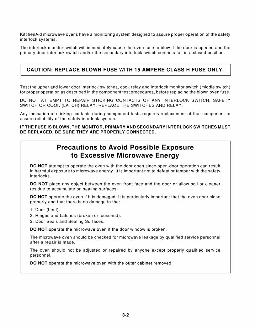
CAUTION: REPLACE BLOWNFUSE WITH 15 AMPERE CLASS HFUSE ONLY.
Before replacing the blown oven fuse, test theupper and lower door interlock switches, cookrelay or latch relay, and interlock monitor switch(middle switch) for proper operation as de-scribed in the component test procedures.
DO NOT ATTEMPT TO REPAIR STICKINGCONTACTS OF ANY INTERLOCK SWITCH,SAFETY SWITCH, OR COOK (LATCH) RE-LAY (REPLACE SWITCHES).
Any indication of sticking contacts during com-ponent test requires replacement of that com-ponent to assure reliability of the safety inter-lock system.
IF THE FUSE IS BLOWN, THE MONITOR,PRIMARY INTERLOCK AND SECONDARYINTERLOCK SWITCHES MUST ALSO BEREPLACED. BE SURE THEY ARE PROP-ERLY CONNECTED.
NOTES:
• For proper repair and assembly of the ovendoor, refer to page 2-4.
• Interlock switches are not adjustable indi-vidually.
• For proper repair and adjustment of theinterlock switches, refer to page 2-8.
WARNINGDISCONNECT FROM POWER SUPPLYBEFORE SERVICING.
CAUTION: HIGH VOLTAGES AREPRESENT DURING THE COOKCYCLE. EXTREME CAUTIONSHOULD BE OBSERVED AT ALLTIMES.
CAUTION: DO NOT TOUCHOVEN COMPONENTS OR WIR-ING DURING OVEN OPERATION.ATTACH METER LEADS WITHALLIGATOR CLIPS WHEN MAK-ING OPERATIONAL TESTS.
CAUTION: IT IS NEITHER NEC-ESSARY NOR ADVISABLE TOATTEMPT MEASUREMENT OFHIGH VOLTAGES.
KitchenAid microwave ovens have a monitor-ing system designed to assure proper opera-tion of the safety interlock systems.
The interlock monitor switch will immediatelycause the oven fuse to blow if the door isopened while the following combined failureexists:
Primary door interlock switch and/or second-ary interlock switch contacts failed in a closedposition.
viii
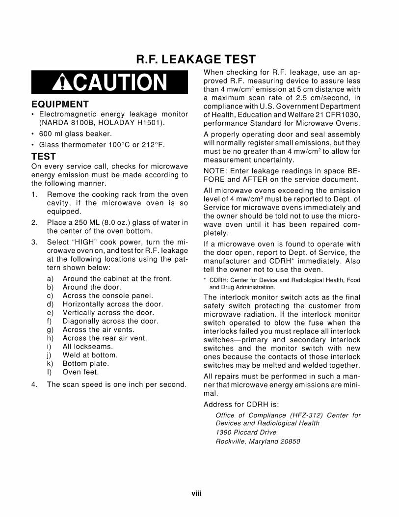
R.F. LEAKAGE TESTWhen checking for R.F. Ieakage, use an ap-proved R.F. measuring device to assure lessthan 4 mw/cm2 emission at 5 cm distance witha maximum scan rate of 2.5 cm/second, incompliance with U.S. Government Departmentof Health, Education and Welfare 21 CFR1030,performance Standard for Microwave Ovens.
A properly operating door and seal assemblywill normally register small emissions, but theymust be no greater than 4 mw/cm2 to allow formeasurement uncertainty.
NOTE: Enter leakage readings in space BE-FORE and AFTER on the service document.
All microwave ovens exceeding the emissionlevel of 4 mw/cm2 must be reported to Dept. ofService for microwave ovens immediately andthe owner should be told not to use the micro-wave oven until it has been repaired com-pletely.
If a microwave oven is found to operate withthe door open, report to Dept. of Service, themanufacturer and CDRH* immediately. Alsotell the owner not to use the oven.* CDRH: Center for Device and Radiological Health, Food
and Drug Administration.
The interlock monitor switch acts as the finalsafety switch protecting the customer frommicrowave radiation. If the interlock monitorswitch operated to blow the fuse when theinterlocks failed you must replace all interlockswitches—primary and secondary interlockswitches and the monitor switch with newones because the contacts of those interlockswitches may be melted and welded together.
All repairs must be performed in such a man-ner that microwave energy emissions are mini-mal.
Address for CDRH is:
Office of Compliance (HFZ-312) Center forDevices and Radiological Health1390 Piccard DriveRockville, Maryland 20850
CAUTIONEQUIPMENT• Electromagnetic energy leakage monitor
(NARDA 8100B, HOLADAY H1501).
• 600 ml glass beaker.
• Glass thermometer 100°C or 212°F.
TESTOn every service call, checks for microwaveenergy emission must be made according tothe following manner.
1. Remove the cooking rack from the ovencavity, i f the microwave oven is soequipped.
2. Place a 250 ML (8.0 oz.) glass of water inthe center of the oven bottom.
3. Select “HIGH” cook power, turn the mi-crowave oven on, and test for R.F. Ieakageat the following locations using the pat-tern shown below:
a) Around the cabinet at the front.b) Around the door.c) Across the console panel.d) Horizontally across the door.e) Vertically across the door.f) Diagonally across the door.g) Across the air vents.h) Across the rear air vent.i) All lockseams.j) Weld at bottom.k) Bottom plate.I) Oven feet.
4. The scan speed is one inch per second.
Microwave Oven Hood Combo Service Manual — LIT 4317216 Page 1-1
1-1
Original 03/97
THEORY OF OPERATIONThe microwave oven is powered by the 120-volt line. Whenever the door is closed and acooking function is programmed through thecontrol panel’s keypad, relay contacts on thecontrol board close, and complete a circuitfrom the L1 side to the neutral side of the line.
The control board uses six relays to operatethe various functions of the microwave oven(shown below). The relays are controlled bythe microcomputer on the control board, andperform the functions shown below.
Relay 4 controls the speed of the blower motorthrough the control panel. The base thermalfuse will also turn the blower motor on to itslow speed if the temperature reaches 133˚F.The schematic configuration for relay 4 isshown in the following diagram. The relay isexplained in further detail on the followingpage.
Relay 1 ........................................................ Oven Light/Fan & Turntable MotorsRelay 2 ........................................................ High Voltage SectionRelay 3 ........................................................ Low-Speed Blower MotorRelay 4 (N.C. Contacts) ........................... Auto Low-Speed Blower MotorRelay 4 (N.O. Contacts) ........................... High-Speed Blower MotorRelay 5 ........................................................ Cooktop LightsRelay 6 ........................................................ Night Lights
RELAY 4
BASETHERMAL
FUSE
(LOW)
(HI)
(C)
(C)
(NC)(NO)
BLOWERMOTOR
L1
1
2
1
CN
3
RELAY RY2
MICROCOMPUTER
RELAY RY4RELAY RY3
RELAY RY1
RELAY RY5
RELAY RY6
CONTROLCIRCUITBOARD

1-2
The normally-closed (N.C.) contacts of relay 4 provide a potential circuit for the Base ThermalFuse (see the following strip circuit). If the base of the oven exceeds 133˚F, the thermal fusecontacts close, and a circuit for the low-speed side of the blower motor is completed, which turnsthe motor on. The low-speed blower will operate until the base temperature drops below 104˚Fand opens the thermal fuse contacts, and turns off.
NL1
15A LINEFUSE
CAVITYTHERMAL
FUSE
MAGNETRONTHERMAL
FUSE
BKBKBK BK
RELAY #4
BASETHERMAL
FUSE
W
BLYL
LOW-VOLTAGETRANSFORMER
W
BLOWERMOTOR
LOW
RD
MICROCOMPUTERBOARD
4 1
7
CAPACITORYR
When the low-speed fan is selected by the user at the control panel, relay 3 and the normally-closed (N.C.) contacts of relay 4, complete the circuit to the low-speed windings of the blowermotor and turn it on.
NL1
15A LINEFUSE
CAVITYTHERMAL
FUSE
MAGNETRONTHERMAL
FUSE
BKBKBK BK
RELAY #4
W
BLBR
LOW-VOLTAGETRANSFORMER
W
BLOWERMOTOR
LOW
RD
RELAY #3
MICROCOMPUTERBOARD
4 1
6
CAPACITORYR
When the high-speed fan is selected by the user at the control panel, the normally-open (N.O.)contacts of relay 4 complete the circuit to the high-speed windings of the blower motor and turnit on.
NL1
15A LINEFUSE
CAVITYTHERMAL
FUSE
MAGNETRONTHERMAL
FUSE
BKBKBK BK
RELAY #4
W
BLBK
LOW-VOLTAGETRANSFORMER
BLOWERMOTOR
HIGH
RD
MICROCOMPUTERBOARD
4 1
8
CAPACITORYR

Page 2-1
2-1
Microwave Oven Hood Combo Service Manual — LIT 4317216Original 03/97
COMPONENT ACCESS
• The Operating Control SystemOven Light SocketControl Circuit BoardTemperature Probe SocketFan MotorPower CordBlower Motor CapacitorConvection Heating ElementGas SensorSynchronous MotorCooktop Light Socket
• The High Voltage ComponentsMagnetronRectifierCapacitorTransformer
Refer to the section on the following pages forthe component you wish to service.
BLOWER MOTOR
CAVITY THERMAL FUSE
HV TRANSFORMER
HV CAPACITOR
HV RECTIFIER
MAGNETRON
MAGNETRON THERMAL FUSE
FAN MOTOR
BLOWER MOTOR CAPACITOR
BASE THERMAL FUSELINE FUSE
CONTROL CIRCUIT BOARD
SECONDARY INTERLOCK SWITCHOVEN LAMP SWITCH
MONITOR SWITCH
COOKTOP LIGHTS
OVEN LIGHT
PRIMARY INTERLOCK SWITCH
GAS SENSOR(NOT ON ALL MODELS)
SYNCHRONOUSMOTOR
CONVECTION HEATING ELEMENT(NOT ON ALL MODELS)
CONVECTION THERMISTOR(NOT ON ALL MODELS)
COMPONENT SECTIONSThis section instructs you on how to servicethe individual components in the MicrowaveOven Hood Combination. These components(shown below) and their sections are as fol-lows:
• GeneralCabinet
• The Protection Control SystemOven DoorDoor ChokeControl PanelLine FuseInterlock SwitchesBase Thermal FuseMagnetron Thermal FuseCavity Thermal FuseConvection Thermistor
Magnetron Thermal Fuse ..........................................Opens @ 302˚F/150˚C, resets @ 140˚F/60˚C.Cavity Thermal Fuse ..............................................Opens @ 230˚F/110˚C, resets @ 140˚F/60˚C.Base Thermal Fuse ................................................. Closes @ 133˚F/56˚C, resets @ 104˚F/40˚C.
2-2
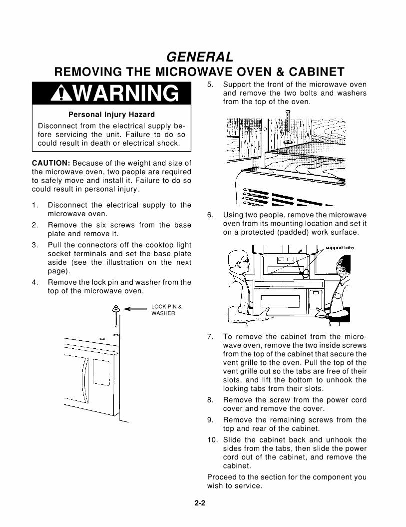
GENERALREMOVING THE MICROWAVE OVEN & CABINET
WARNINGPersonal Injury Hazard
Disconnect from the electrical supply be-fore servicing the unit. Failure to do socould result in death or electrical shock.
CAUTION: Because of the weight and size ofthe microwave oven, two people are requiredto safely move and install it. Failure to do socould result in personal injury.
7. To remove the cabinet from the micro-wave oven, remove the two inside screwsfrom the top of the cabinet that secure thevent grille to the oven. Pull the top of thevent grille out so the tabs are free of theirslots, and lift the bottom to unhook thelocking tabs from their slots.
8. Remove the screw from the power cordcover and remove the cover.
9. Remove the remaining screws from thetop and rear of the cabinet.
10. Slide the cabinet back and unhook thesides from the tabs, then slide the powercord out of the cabinet, and remove thecabinet.
Proceed to the section for the component youwish to service.
5. Support the front of the microwave ovenand remove the two bolts and washersfrom the top of the oven.
6. Using two people, remove the microwaveoven from its mounting location and set iton a protected (padded) work surface.
LOCK PIN &WASHER
1. Disconnect the electrical supply to themicrowave oven.
2. Remove the six screws from the baseplate and remove it.
3. Pull the connectors off the cooktop lightsocket terminals and set the base plateaside (see the illustration on the nextpage).
4. Remove the lock pin and washer from thetop of the microwave oven.
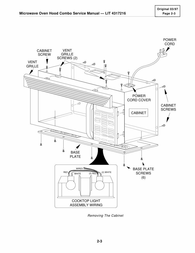
Page 2-3
2-3
Microwave Oven Hood Combo Service Manual — LIT 4317216Original 03/97
POWERCORD
POWERCORD COVER
BASEPLATE
REDWHITE (2) RED (2) WHITE
COOKTOP LIGHTASSEMBLY WIRING
WIRES
CABINET
CABINETSCREW
VENTGRILLE
SCREWS (2)
CABINETSCREWS
VENTGRILLE
BASE PLATESCREWS
(6)
Removing The Cabinet

2-4
THE PROTECTION CONTROL SYSTEMREMOVING THE OVEN DOOR
WARNINGPersonal Injury Hazard
Disconnect from the electrical supply be-fore servicing the unit. Failure to do socould result in death or electrical shock.
CAUTION: Because of the weight and size ofthe microwave oven, two people are requiredto safely move and install it. Failure to do socould result in personal injury.
1. Disconnect the electrical supply to themicrowave oven.
2. Remove the vent grille and the base platefrom the microwave oven (see the illus-tration on page 2-3).
3. Remove the six oven door hinge screwsand remove the door.
4. Install the new oven door and then reas-semble the microwave oven.
REASSEMBLY NOTE: Make sure that youopen and close the door several times to makesure that it operates properly before you reas-semble the oven.
HINGEMOUNTINGSCREWS
HINGEMOUNTINGSCREWS
Page 2-5
2-5
Microwave Oven Hood Combo Service Manual — LIT 4317216Original 03/97
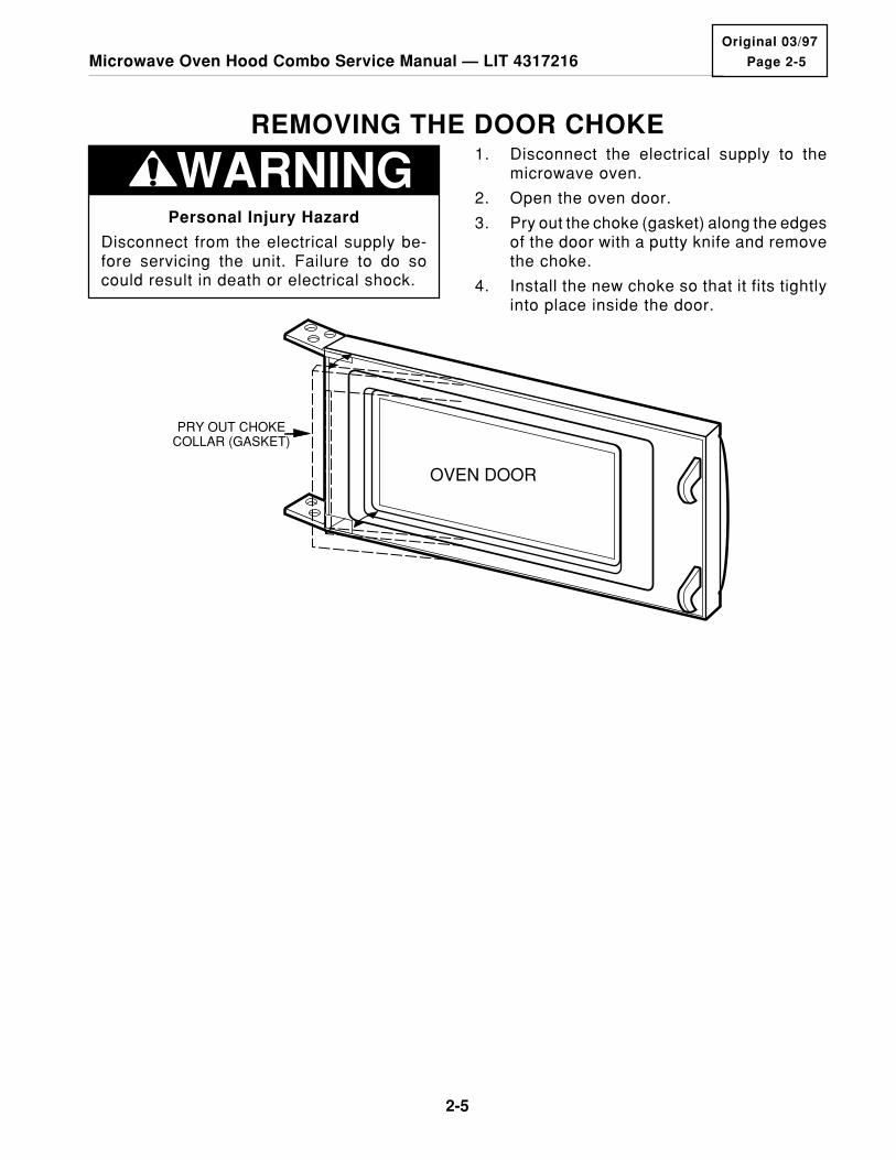
REMOVING THE DOOR CHOKE
WARNINGPersonal Injury Hazard
Disconnect from the electrical supply be-fore servicing the unit. Failure to do socould result in death or electrical shock.
1. Disconnect the electrical supply to themicrowave oven.
2. Open the oven door.
3. Pry out the choke (gasket) along the edgesof the door with a putty knife and removethe choke.
4. Install the new choke so that it fits tightlyinto place inside the door.
OVEN DOOR
PRY OUT CHOKECOLLAR (GASKET)

2-6
WARNINGPersonal Injury Hazard
Disconnect from the electrical supply be-fore servicing the unit. Failure to do socould result in death or electrical shock.
REMOVING THE CONTROL PANEL
1. Disconnect the electrical supply to themicrowave oven.
2. Remove the two screws from the top ofthe cabinet for the vent grille and removethe grille (see the illustration on page2-3).
3. Remove the screw from the top center tabof the control panel.
4. From the top and back of the controlpanel, lift the top locking tab and pullthe top of the panel out slightly, then liftthe bottom tabs of the panel out of theslots and pull it forward. Turn the panelover out of the way.
1
TURN PANEL OVER
TOPLOCKING
TABCONTROL
PANEL
BOTTOMTABS
BOTTOMSLOTS
TABSLOT
MOUNTINGSCREW
TOP CENTERTAB
SLOTTAB
Page 2-7
2-7
Microwave Oven Hood Combo Service Manual — LIT 4317216Original 03/97
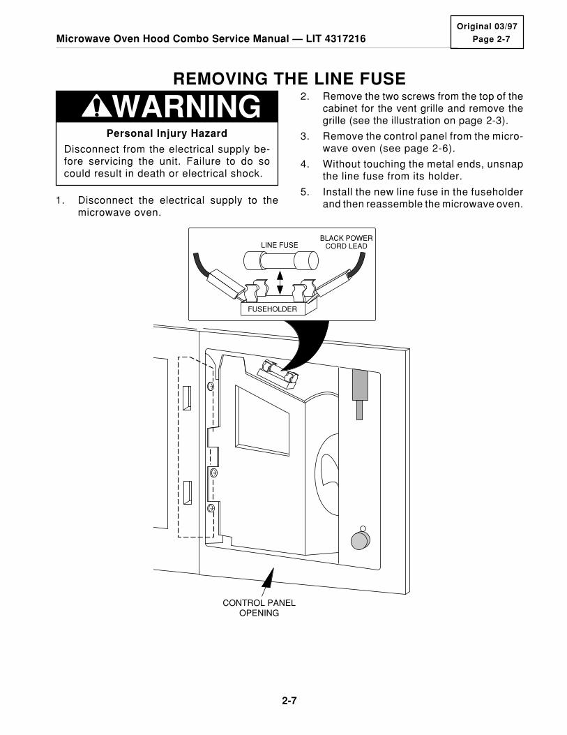
REMOVING THE LINE FUSE
Personal Injury Hazard
Disconnect from the electrical supply be-fore servicing the unit. Failure to do socould result in death or electrical shock.
WARNING 2. Remove the two screws from the top of thecabinet for the vent grille and remove thegrille (see the illustration on page 2-3).
3. Remove the control panel from the micro-wave oven (see page 2-6).
4. Without touching the metal ends, unsnapthe line fuse from its holder.
5. Install the new line fuse in the fuseholderand then reassemble the microwave oven.
CONTROL PANELOPENING
LINE FUSE
FUSEHOLDER
BLACK POWER CORD LEAD
1. Disconnect the electrical supply to themicrowave oven.
2-8
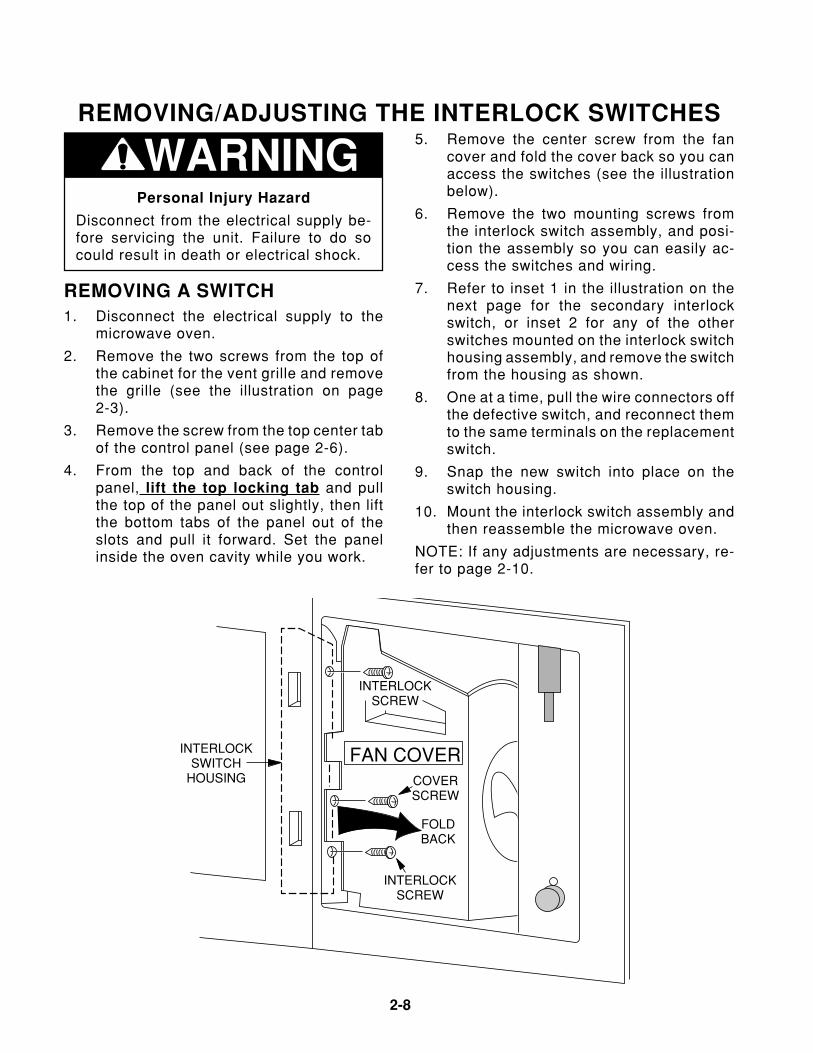
REMOVING/ADJUSTING THE INTERLOCK SWITCHES
WARNINGPersonal Injury Hazard
Disconnect from the electrical supply be-fore servicing the unit. Failure to do socould result in death or electrical shock.
5. Remove the center screw from the fancover and fold the cover back so you canaccess the switches (see the illustrationbelow).
6. Remove the two mounting screws fromthe interlock switch assembly, and posi-tion the assembly so you can easily ac-cess the switches and wiring.
7. Refer to inset 1 in the illustration on thenext page for the secondary interlockswitch, or inset 2 for any of the otherswitches mounted on the interlock switchhousing assembly, and remove the switchfrom the housing as shown.
8. One at a time, pull the wire connectors offthe defective switch, and reconnect themto the same terminals on the replacementswitch.
9. Snap the new switch into place on theswitch housing.
10. Mount the interlock switch assembly andthen reassemble the microwave oven.
NOTE: If any adjustments are necessary, re-fer to page 2-10.
REMOVING A SWITCH1. Disconnect the electrical supply to the
microwave oven.
2. Remove the two screws from the top ofthe cabinet for the vent grille and removethe grille (see the illustration on page2-3).
3. Remove the screw from the top center tabof the control panel (see page 2-6).
4. From the top and back of the controlpanel, lift the top locking tab and pullthe top of the panel out slightly, then liftthe bottom tabs of the panel out of theslots and pull it forward. Set the panelinside the oven cavity while you work.
FAN COVERCOVERSCREW
INTERLOCKSCREW
INTERLOCKSCREW
FOLDBACK
INTERLOCKSWITCH
HOUSING

Page 2-9
2-9
Microwave Oven Hood Combo Service Manual — LIT 4317216Original 03/97
PRESS BODY IN THIS DIRECTION TOREMOVE SWITCHFROM HOUSING.
2.
1. RAISE THIS LOCKINGARM TO RELEASESWITCH FROM HOUSING.
1. PUSH THIS LOCKINGARM BACK TO UNLOCKSWITCH.
2. ROTATE SWITCH ON THISPIN AND REMOVESWITCH FROM HOUSING.
NOTE: THESE POSTSHOLD THE SWITCH INPLACE ON THE HOUSINGAND ARE STATIONARY.
ALL OTHERSWITCHES
SECONDARYINTERLOCK
SWITCH
INSET 1 INSET 2
WHITE (H.V. Transformer)RED (Monitor Switch)
LARGE WHITE (Power Cord)SMALL WHITE (Oven Lamp)
PINK (Controller)BLACK (Fan Motor)
RED (Magnetron Thermostat)
BROWN (Temp Probe)
WHITE (H.V. Transformer)
BLUE (Oven Lamp)
RED (Secondary Switch)
BLUE (Temp Probe)Blue (CN2 Pin 3)
PINK (CN2 Pin 1)
SECONDARY INTERLOCKSWITCH
OVEN LAMP CONTROLSWITCH
INTERLOCK MONITORSWITCH
PRIMARY INTERLOCKSWITCH
INTERLOCK SWITCHHOUSING ASSEMBLY
Interlock Switch Wiring

2-10
MAKING ADJUSTMENTS1. If necessary, adjust the interlock switch
housing so that the switches operate prop-erly. NOTE: The Interlock Monitor Switchprovides an added safety check on thePrimary and Secondary Interlock Switches.If the Primary and Secondary InterlockSwitches allow the oven to operate withthe door open, the Interlock Monitor Switchwill blow the line fuse.
2. Close and secure the fan cover with itsmounting screw.
3. Mount the control panel to the oven withthe screw you removed earlier.
4. Mount the vent grille to the microwaveoven and check out the operation of theswitches.
DOOR LATCH
DOOR LATCH
CHECK GAP HERE
CHECK GAP HERE
LATCHHOUSING
OVEN LAMPCONTROLSWITCH
INTERLOCKMONITORSWITCH
PRIMARYINTERLOCKSWITCH
SECONDARYINTERLOCKSWITCH
Page 2-11
2-11
Microwave Oven Hood Combo Service Manual — LIT 4317216Original 03/97
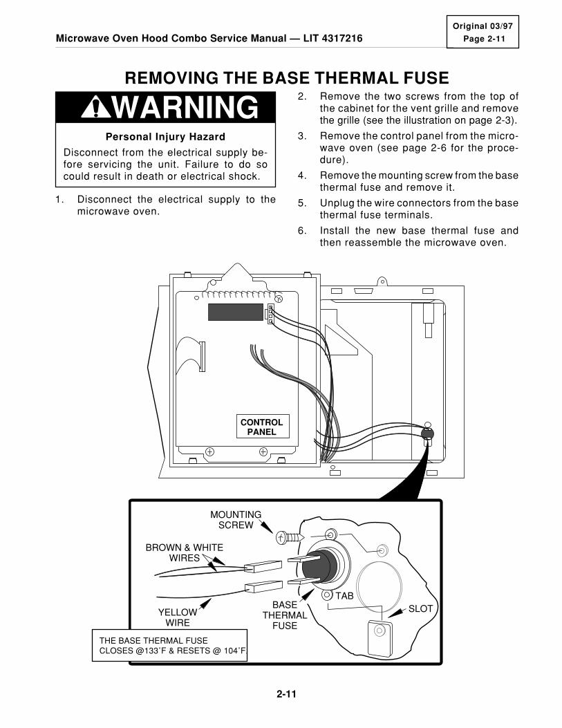
REMOVING THE BASE THERMAL FUSE
WARNINGPersonal Injury Hazard
Disconnect from the electrical supply be-fore servicing the unit. Failure to do socould result in death or electrical shock.
2. Remove the two screws from the top ofthe cabinet for the vent grille and removethe grille (see the illustration on page 2-3).
3. Remove the control panel from the micro-wave oven (see page 2-6 for the proce-dure).
4. Remove the mounting screw from the basethermal fuse and remove it.
5. Unplug the wire connectors from the basethermal fuse terminals.
6. Install the new base thermal fuse andthen reassemble the microwave oven.
CONTROLPANEL
BROWN & WHITEWIRES
TABBASE
THERMALFUSE
SLOT
MOUNTINGSCREW
YELLOWWIRE
THE BASE THERMAL FUSECLOSES @133˚F & RESETS @ 104˚F.
1. Disconnect the electrical supply to themicrowave oven.

2-12
REMOVING THE MAGNETRON THERMAL FUSE
WARNINGPersonal Injury Hazard
Disconnect from the electrical supply be-fore servicing the unit. Failure to do socould result in death or electrical shock.
Discharge the high voltage capacitor be-fore working inside the oven. Failure to doso could result in death or electrical shock.
the grille (see the illustration on page2-3).
3. Remove the control panel from the micro-wave oven (see page 2-6).
4. Remove the center screw from the fancover and fold the cover back so you canaccess the magnetron thermal fuse.
5. Unplug the wire connectors from the mag-netron thermal fuse on the side of themagnetron.
6. Remove the two screws from the magne-tron thermal fuse and remove it.
7. Mount the new magnetron thermal fuse tothe magnetron and then reassemble themicrowave oven.
FAN COVERCOVERSCREW
FOLDBACK
BLACK & REDWIRES
BLACK WIRE
MAGNETRON THERMAL
FUSE
MAGNETRON
1. Disconnect the electrical supply to themicrowave oven.
2. Remove the two screws from the top ofthe cabinet for the vent grille and remove
THE MAGNETRON THERMAL FUSEOPENS @ 302˚F AND RESETS @ 140˚F.

Page 2-13
2-13
Microwave Oven Hood Combo Service Manual — LIT 4317216Original 03/97
REMOVING THE CAVITY THERMAL FUSE1. Disconnect the electrical supply to the
microwave oven.
2. Remove the microwave oven from itsmounting location (refer to page 2-2 forthe procedure).
3. Remove the vent grille and the cabinetfrom the microwave oven (refer to page 2-2 for the procedure).
4. Unplug the wire connectors from the ter-minals of the cavity thermal fuse, thenstraighten the tabs, and remove the ther-mal fuse.
5. Install the new cavity thermal fuse andthen reassemble the microwave oven.
WARNINGPersonal Injury Hazard
Disconnect from the electrical supply be-fore servicing the unit. Failure to do socould result in death or electrical shock.
Discharge the high voltage capacitor be-fore working inside the oven. Failure to doso could result in death or electrical shock.
CAUTION: Because of the weight and size ofthe microwave oven, two people are requiredto safely move and install it. Failure to do socould result in personal injury.
CAVITY THERMAL
FUSE
TABS
THE CAVITY THERMAL FUSE OPENS AT 230˚FAND RESETS AT 140˚F
2-14
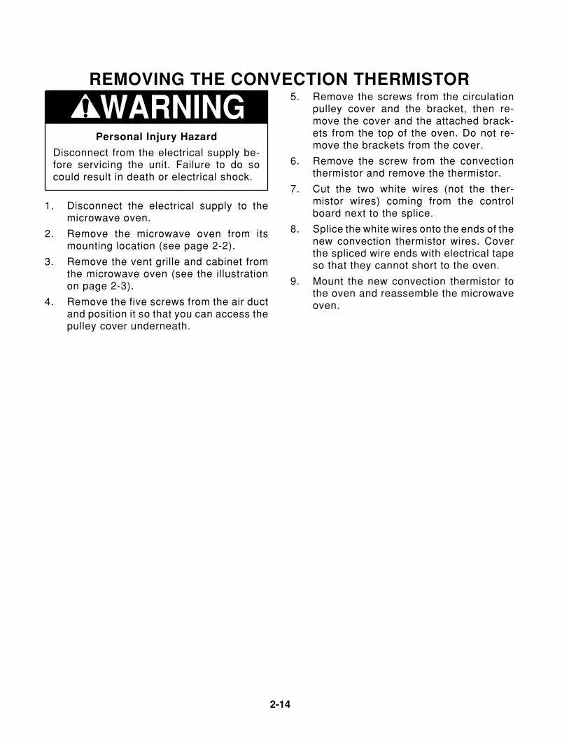
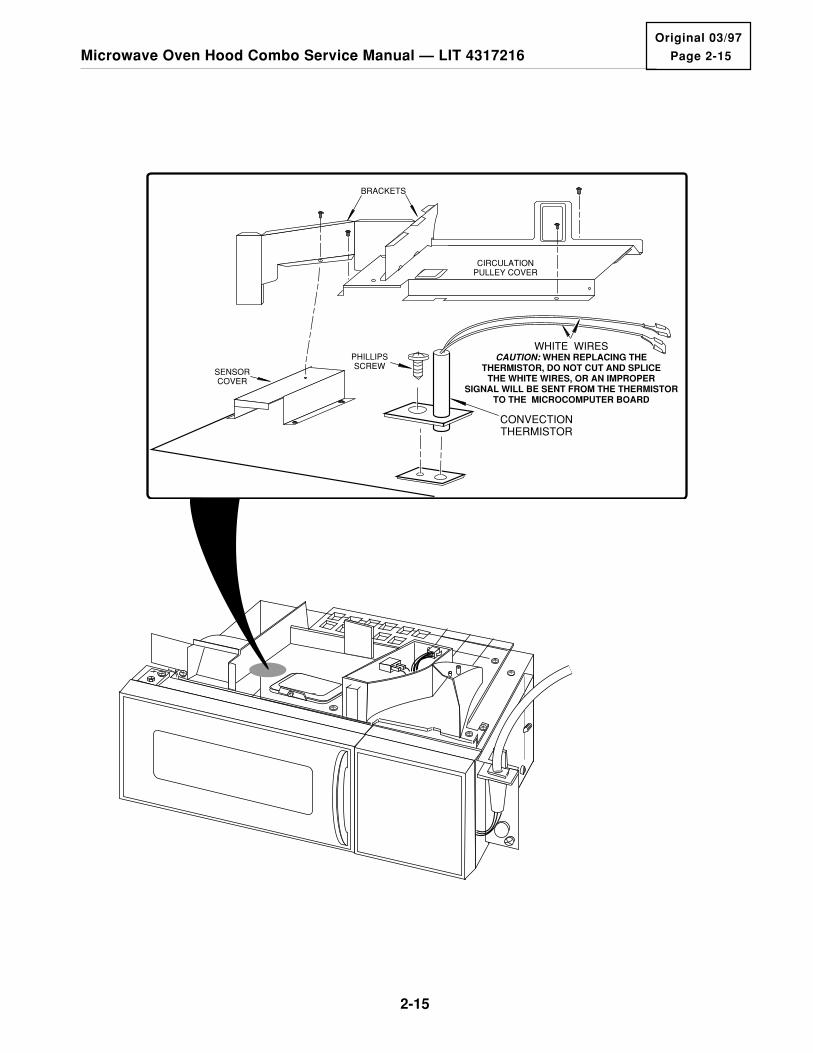
REMOVING THE CONVECTION THERMISTOR
WARNINGPersonal Injury Hazard
Disconnect from the electrical supply be-fore servicing the unit. Failure to do socould result in death or electrical shock.
1. Disconnect the electrical supply to themicrowave oven.
2. Remove the microwave oven from itsmounting location (see page 2-2).
3. Remove the vent grille and cabinet fromthe microwave oven (see the illustrationon page 2-3).
4. Remove the five screws from the air ductand position it so that you can access thepulley cover underneath.
5. Remove the screws from the circulationpulley cover and the bracket, then re-move the cover and the attached brack-ets from the top of the oven. Do not re-move the brackets from the cover.
6. Remove the screw from the convectionthermistor and remove the thermistor.
7. Cut the two white wires (not the ther-mistor wires) coming from the controlboard next to the splice.
8. Splice the white wires onto the ends of thenew convection thermistor wires. Coverthe spliced wire ends with electrical tapeso that they cannot short to the oven.
9. Mount the new convection thermistor tothe oven and reassemble the microwaveoven.
Page 2-15
2-15
Microwave Oven Hood Combo Service Manual — LIT 4317216Original 03/97
PHILLIPSSCREW
SENSORCOVER
CONVECTIONTHERMISTOR
WHITE WIRESCAUTION: WHEN REPLACING THE
THERMISTOR, DO NOT CUT AND SPLICE THE WHITE WIRES, OR AN IMPROPER
SIGNAL WILL BE SENT FROM THE THERMISTOR TO THE MICROCOMPUTER BOARD
BRACKETS
CIRCULATIONPULLEY COVER
2-16
THE OPERATING CONTROL SYSTEM
WARNINGPersonal Injury Hazard
Disconnect from the electrical supply be-fore servicing the unit. Failure to do socould result in death or electrical shock.
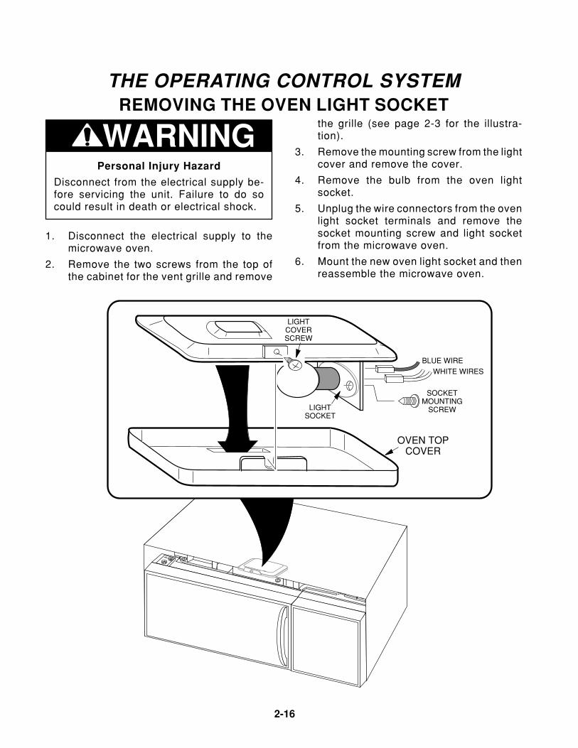
REMOVING THE OVEN LIGHT SOCKET
1. Disconnect the electrical supply to themicrowave oven.
2. Remove the two screws from the top ofthe cabinet for the vent grille and remove
the grille (see page 2-3 for the illustra-tion).
3. Remove the mounting screw from the lightcover and remove the cover.
4. Remove the bulb from the oven lightsocket.
5. Unplug the wire connectors from the ovenlight socket terminals and remove thesocket mounting screw and light socketfrom the microwave oven.
6. Mount the new oven light socket and thenreassemble the microwave oven.
WHITE WIRESBLUE WIRE
SOCKETMOUNTING
SCREW
LIGHTCOVERSCREW
LIGHTSOCKET
OVEN TOPCOVER

Page 2-17
2-17
Microwave Oven Hood Combo Service Manual — LIT 4317216Original 03/97
REMOVING THE CONTROL CIRCUIT BOARD
WARNINGPersonal Injury Hazard
Disconnect from the electrical supply be-fore servicing the unit. Failure to do socould result in death or electrical shock.
1. Disconnect the electrical supply to themicrowave oven.
2. Remove the two screws from the top ofthe cabinet for the vent grille and removethe grille (see the illustration on page2-3).
3. Remove the screw from the top center tabof the control panel.
4. From the top and back of the controlpanel, lift the top locking tab and pullthe top of the panel out slightly, then liftthe bottom tabs of the panel out of theslots, pull it forward, and turn it over.
1
2
CN1
CN2
RY2
CN
4
14
1
CN
3
TURN BOARD OVER
CIRCUITBOARDSCREW
(4)
TOP LOCKINGTAB
SLIDEBOARD UNDER
BRACKET
CONTROLCIRCUITBOARD
CONTROLPANEL
BOTTOMTABS
BOTTOMSLOTS
TABSLOT
RIBBONCABLE
TOP CENTER TAB
MOUNTING SCREW
SLOTTAB
TECH SHEET
UNSNAP/SNAP LOCKINGARMS ON COLLAR TO
BOTTOM SIDE OF CONNECTOR
INSERT CABLE INTO REAR CONTACT SLOT
RIBBON CABLE
COLLAR
CONNECTORCN3
INSET
5. Unplug the following connectors from thecontrol circuit board:
a) 3-wire connector at CN4.b) 2-wire connector at CN2.c) 2 connectors on relay RY2.d) 8-wire connector at CN1.e) Lift the ribbon cable collar at CN3 as
far as it will go, (see the inset), thenunsnap the locking arms on the collarfrom the sides of the connector, andlift the ribbon cable out of the socket.
6. Remove the four screws from the controlcircuit board and lift the board off themounting bracket.
7. Clean the surface of the new display andthe inside of the control panel windowwith a soft, damp cloth to remove any dirt,smudges, or lint.
8. Mount the new control circuit board to themounting bracket with four screws andthen reassemble the microwave oven.

2-18
FAN COVERCOVERSCREW
FOLDBACK
FLATWASHER
HEXNUT
BLUE WIRE
BROWN WIRE
TEMPERATUREPROBE SOCKET
REMOVING THE TEMPERATURE PROBE SOCKET4. From the top and back of the control
panel, lift the top locking tab and pullthe top of the panel out slightly, then liftthe bottom tabs of the panel out of theslots and pull it forward. Set the panelinside the oven cavity while you work.
5. Remove the center screw from the fancover and fold the cover back (unhook thethree tabs) so you can access the tem-perature probe socket.
6 Remove the hex nut and flat washer fromthe temperature probe socket, and re-move the socket from its mounting hole inthe oven.
7. Unsolder the two wires from the tempera-ture probe socket.
8. Mount the new temperature probe socketand reassemble the microwave oven.
WARNINGPersonal Injury Hazard
Disconnect from the electrical supply be-fore servicing the unit. Failure to do socould result in death or electrical shock.
1. Disconnect the electrical supply to themicrowave oven.
2. Remove the two screws from the top ofthe cabinet for the vent grille and removethe grille (see the illustration on page2-3).
3. Remove the screw from the top center tabof the control panel (see the illustrationon page 2-17).

Page 2-19
2-19
Microwave Oven Hood Combo Service Manual — LIT 4317216Original 03/97
REMOVING THE FAN MOTOR
WARNINGPersonal Injury Hazard
Disconnect from the electrical supply be-fore servicing the unit. Failure to do socould result in death or electrical shock.
2. Remove the microwave oven from itsmounting location.
3. Remove the vent grille and the cabinetfrom the microwave oven (refer to page2-2 for the procedure).
4. Unplug the wire connectors going to theline fuse.
5. Disconnect the wires from the terminalsof the base thermal fuse.
6. Remove the five screws from the rightside panel and remove the panel.
7. Remove the screw from the fan cover andfold it back.
8. Remove the fan motor housing screw fromthe magnetron and the chassis screw.
9. Unplug the fan motor wire connectorsfrom the motor terminals.
10. Pull the fan motor housing assembly outthe right side of the microwave oven andremove it.
11. Pull the fan blade and compression washeroff the shaft of the fan motor.
12. Remove the two motor mounting screwsfrom the fan motor and remove it.
13. Mount the new fan motor to the fan motorhousing and then reassemble the micro-wave oven.
CAUTION: Because of the weight and size ofthe microwave oven, two people are requiredto safely move and install it. Failure to do socould result in personal injury.
PRESS-ONWASHER
FAN COVERSCREW
FOLDBACK
FAN MOTORHOUSING SCREW
CHASSISSCREW
MOTORMOUNTINGSCREWS
FANMOTOR
FANBLADE
BROWN
BLUEYELLOW
BLUE
FAN MOTORHOUSING
FANMOTOR
HOUSING
BASETHERMAL
FUSE
POWERCORD
STRAIN RELIEFBLOCK
BLACK
WIRING HARNESSCONNECTOR
RIGHTSIDE
PANEL
MOUNTINGSCREW (5)
GREENWHITE
1. Disconnect the electrical supply to themicrowave oven.

2-20
REMOVING THE POWER CORD
WARNINGPersonal Injury Hazard
Disconnect from the electrical supply be-fore servicing the unit. Failure to do socould result in death or electrical shock.
CAUTION: Because of the weight and size ofthe microwave oven, two people are requiredto safely move and install it. Failure to do socould result in personal injury.
1. Disconnect the electrical supply to themicrowave oven.
2. Remove the microwave oven from itsmounting location (refer to page 2-2 forthe procedure).
3. Remove the vent grille and the cabinetfrom the microwave oven (see page 2-2).
4. Remove the three mounting screws hold-ing the top of the right side panel to theplastic cover.
5. Raise the plastic cover just enough toslide the power cord strain relief block outof the chassis slot.
6. Unplug the black and white power cordleads. NOTE: Disconnect the black leadby pressing in on the locking arm of theconnector and pulling it loose.
7. Remove the ground screw from the greenpower cord lead.
8. Remove the old power cord.
9. Raise the cover just enough to slide thenew power cord strain relief block into thechassis slot, then reconnect the leadsand reassemble the microwave oven.
FAN MOTORCONNECTOR
RIGHTSIDE
PANEL
(3)TOP RIGHT SIDE PANEL
SCREWS
POWERCORD
STRAINRELIEFBLOCK
SLIDEOVER
CHASSIS
COVERSCREW
TO LINE FUSE
WIRING HARNESSCONNECTOR
WHITE
GREEN
GROUNDSCREW LINE
FUSE
PLASTICCOVER
BLACK
Page 2-21
2-21
Microwave Oven Hood Combo Service Manual — LIT 4317216Original 03/97
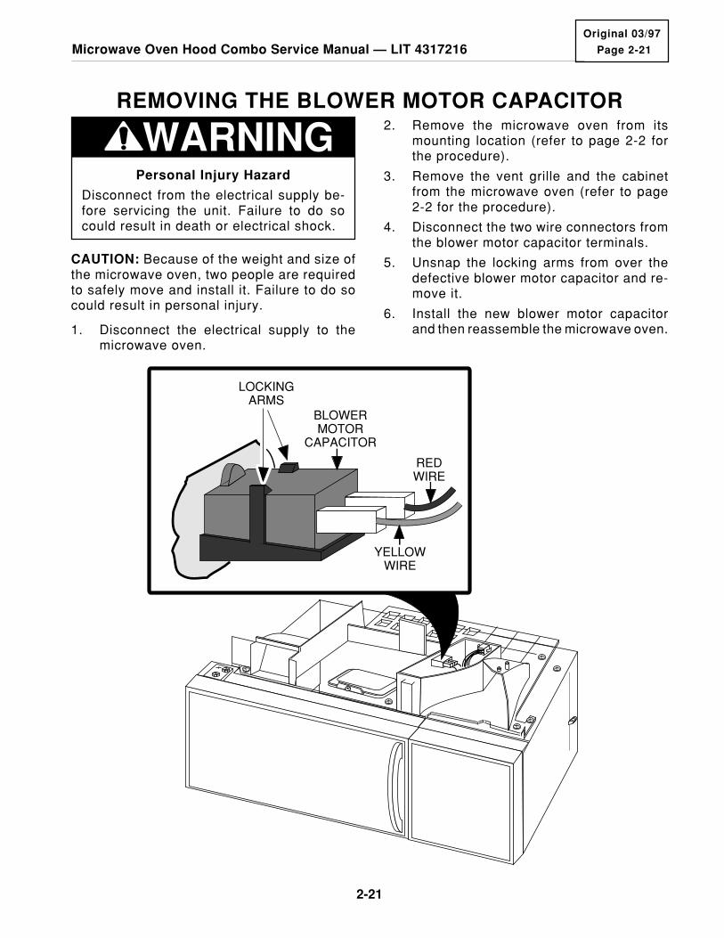
REMOVING THE BLOWER MOTOR CAPACITOR2. Remove the microwave oven from its
mounting location (refer to page 2-2 forthe procedure).
3. Remove the vent grille and the cabinetfrom the microwave oven (refer to page2-2 for the procedure).
4. Disconnect the two wire connectors fromthe blower motor capacitor terminals.
5. Unsnap the locking arms from over thedefective blower motor capacitor and re-move it.
6. Install the new blower motor capacitorand then reassemble the microwave oven.
BLOWERMOTOR
CAPACITOR
REDWIRE
YELLOWWIRE
LOCKINGARMS
WARNINGPersonal Injury Hazard
Disconnect from the electrical supply be-fore servicing the unit. Failure to do socould result in death or electrical shock.
CAUTION: Because of the weight and size ofthe microwave oven, two people are requiredto safely move and install it. Failure to do socould result in personal injury.
1. Disconnect the electrical supply to themicrowave oven.

2-22
REMOVING THE CONVECTION HEATING ELEMENT
WARNINGPersonal Injury Hazard
Disconnect from the electrical supply be-fore servicing the unit. Failure to do socould result in death or electrical shock.
1. Disconnect the electrical supply to themicrowave oven.
2. Remove the microwave oven from itsmounting location (see page 2-2).
3. Remove the vent grille and cabinet fromthe microwave oven (see the illustrationon page 2-3).
4. Remove the five screws from the air duct,then lift the duct and postion it so you canaccess the convection heating element.
5. Remove the three phillips screws fromthe circulation pulley cover and the onefrom the bracket, and remove the coverand attached brackets from the top of theoven. Do not remove the brackets fromthe cover.
6. Remove the screw from the gas sensorand position the sensor out of the way.
7. Unhook the drive belt from the circulationfan pulleys and set it aside.
8. Remove the phillips screw from the con-vection thermistor that is located on thetop plate. Remove the thermistor andposition it out of the way.
9. Disconnect the wires from the convectionheating element terminals.
10. Remove the phillips screws from the topcover, remove it from the oven, and turn itover.
11. Remove the two phillips screws from theconvection heating element bracket.Unclip the element from the cover andremove it.
12. Install the new heating element into themounting clips in the top cover, and se-cure the mounting bracket with two phillipsscrews.
13. Reassemble the microwave oven.

Page 2-23
2-23
Microwave Oven Hood Combo Service Manual — LIT 4317216Original 03/97
CONVECTIONTHERMISTOR
TOP PLATEMOUNTING SCREWS
BRACKETS
CIRCULATIONPULLEY COVER
TOP PLATE
CONVECTIONHEATINGELEMENT
YELLOWWIRES
UNCLIPELEMENT
HERE
HEATING ELEMENT
HEATING ELEMENTMOUNTING SCREWS
VIEWED FROM UNDERTOP PLATE
GAS SENSOR
SENSORCOVER

2-24
REMOVING THE GAS SENSOR
WARNINGPersonal Injury Hazard
Disconnect from the electrical supply be-fore servicing the unit. Failure to do socould result in death or electrical shock.
Discharge the high voltage capacitor be-fore working inside the oven. Failure to doso could result in death or electrical shock.
1. Disconnect the electrical supply to themicrowave oven.
2. Remove the microwave oven from itsmounting location (refer to page 2-2 forthe procedure).
3. Remove the vent grille and the cabinetfrom the microwave oven (refer to page2-2 for the procedure).
4. Unclip the gas sensor cover and removeit.
5. Remove the screw from the top center tabof the control panel (see the illustrationon page 2-17).
6. From the top and back of the controlpanel, lift the top locking tab and pullthe top of the panel out slightly, then liftthe bottom tabs of the panel out of theslots and pull it forward (see page 2-17).
7. Unplug 3-wire gas sensor connector CN4from the control circuit board and removethe gas sensor from the microwave oven.
8. Install the new gas sensor and then reas-semble the microwave oven.
GAS SENSORASSEMBLY
RED
PINS
WHTYEL
COVER
CAUTION: Because of the weight and size ofthe microwave oven, two people are requiredto safely move and install it. Failure to do socould result in personal injury.
Page 2-25
2-25
Microwave Oven Hood Combo Service Manual — LIT 4317216Original 03/97
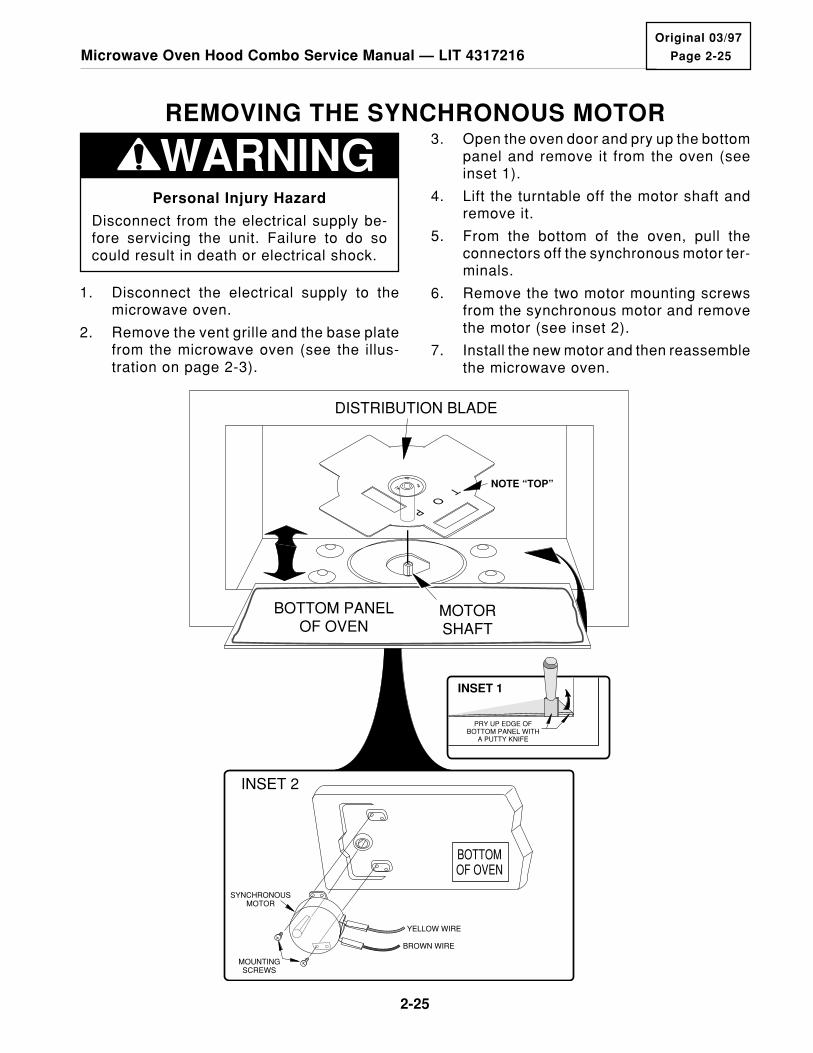
REMOVING THE SYNCHRONOUS MOTOR
WARNINGPersonal Injury Hazard
Disconnect from the electrical supply be-fore servicing the unit. Failure to do socould result in death or electrical shock.
3. Open the oven door and pry up the bottompanel and remove it from the oven (seeinset 1).
4. Lift the turntable off the motor shaft andremove it.
5. From the bottom of the oven, pull theconnectors off the synchronous motor ter-minals.
6. Remove the two motor mounting screwsfrom the synchronous motor and removethe motor (see inset 2).
7. Install the new motor and then reassemblethe microwave oven.
1. Disconnect the electrical supply to themicrowave oven.
2. Remove the vent grille and the base platefrom the microwave oven (see the illus-tration on page 2-3).
T O P
DISTRIBUTION BLADE
MOTORSHAFT
SYNCHRONOUSMOTOR
MOUNTINGSCREWS
BOTTOMOF OVEN
YELLOW WIRE
BROWN WIRE
BOTTOM PANELOF OVEN
INSET 2
NOTE “TOP”
PRY UP EDGE OFBOTTOM PANEL WITH
A PUTTY KNIFE
INSET 1
2-26
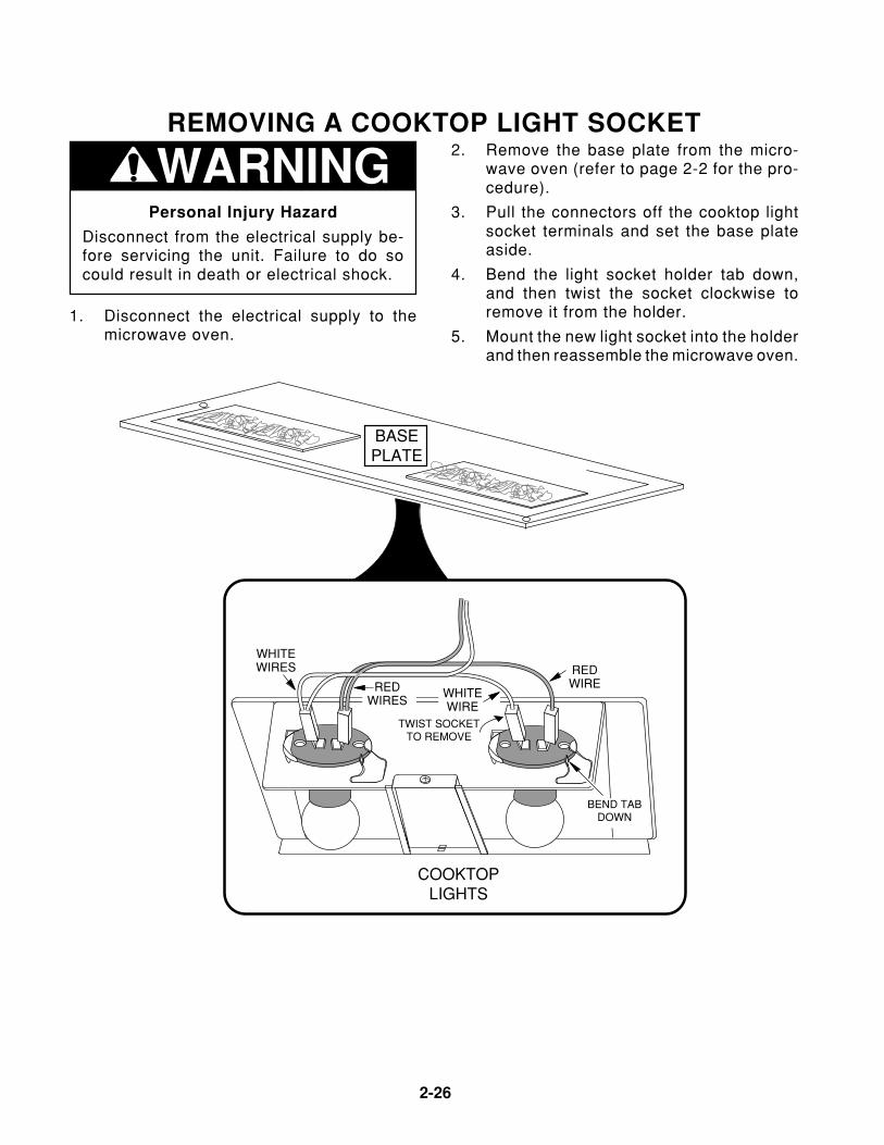
REMOVING A COOKTOP LIGHT SOCKET
WARNINGPersonal Injury Hazard
Disconnect from the electrical supply be-fore servicing the unit. Failure to do socould result in death or electrical shock.
2. Remove the base plate from the micro-wave oven (refer to page 2-2 for the pro-cedure).
3. Pull the connectors off the cooktop lightsocket terminals and set the base plateaside.
4. Bend the light socket holder tab down,and then twist the socket clockwise toremove it from the holder.
5. Mount the new light socket into the holderand then reassemble the microwave oven.
1. Disconnect the electrical supply to themicrowave oven.
BEND TABDOWN
TWIST SOCKETTO REMOVE
COOKTOPLIGHTS
WHITEWIRES
REDWIRES
REDWIRE
WHITEWIRE
BASEPLATEBASEPLATE

Page 2-27
2-27
Microwave Oven Hood Combo Service Manual — LIT 4317216Original 03/97
THE HIGH VOLTAGE COMPONENTSThe components for service in this sectioninclude the:
MagnetronHigh Voltage RectifierHigh Voltage CapacitorHigh Voltage Transformer
The locations of the high voltage componentsare shown in the illustration below. To accessthe high voltage components, perform the stepson the next page.
WARNINGPersonal Injury Hazard
Disconnect from the electrical supply be-fore servicing the unit. Failure to do socould result in death or electrical shock.
Discharge the high voltage capacitor be-fore working inside the oven. Failure to doso could result in electrical shock or otherpersonal injury.
MAGNETRON
HIGH VOLTAGECAPACITOR
HIGH VOLTAGETRANSFORMER
HIGH VOLTAGERECTIFIER
2-28
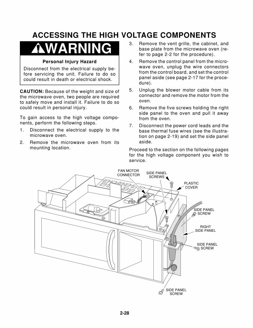
ACCESSING THE HIGH VOLTAGE COMPONENTS3. Remove the vent grille, the cabinet, and
base plate from the microwave oven (re-fer to page 2-2 for the procedure).
4. Remove the control panel from the micro-wave oven, unplug the wire connectorsfrom the control board, and set the controlpanel aside (see page 2-17 for the proce-dure).
5. Unplug the blower motor cable from itsconnector and remove the motor from theoven.
6. Remove the five screws holding the rightside panel to the oven and pull it awayfrom the oven.
7. Disconnect the power cord leads and thebase thermal fuse wires (see the illustra-tion on page 2-19) and set the side panelaside.
Proceed to the section on the following pagesfor the high voltage component you wish toservice.
FAN MOTORCONNECTOR
RIGHTSIDE PANEL
SIDE PANELSCREW
PLASTICCOVER
SIDE PANELSCREW
SIDE PANELSCREW
SIDE PANELSCREWS
WARNINGPersonal Injury Hazard
Disconnect from the electrical supply be-fore servicing the unit. Failure to do socould result in death or electrical shock.
CAUTION: Because of the weight and size ofthe microwave oven, two people are requiredto safely move and install it. Failure to do socould result in personal injury.
To gain access to the high voltage compo-nents, perform the following steps.
1. Disconnect the electrical supply to themicrowave oven.
2. Remove the microwave oven from itsmounting location.

Page 2-29
2-29
Microwave Oven Hood Combo Service Manual — LIT 4317216Original 03/97
REMOVING THE MAGNETRON
WARNINGPersonal Injury Hazard
Disconnect from the electrical supply be-fore servicing the unit. Failure to do socould result in death or electrical shock.
CAUTION: Because of the weight and size ofthe microwave oven, two people are requiredto safely move and install it. Failure to do socould result in personal injury.
1. Disconnect the electrical supply to themicrowave oven.
2. Refer to page 2-28 for accessing the highvoltage components.
5. Remove the fan motor assembly from theunit (see the illustration on page 2-19 forthe procedure).
6. Unplug the wire connectors from the mag-netron thermal fuse.
7. Remove the two screws from the magne-tron thermal fuse and remove it.
8. Unplug the red and white connectors fromthe high-voltage terminals of the magne-tron.
9. Remove the four mounting screws fromthe magnetron. NOTE: Support the mag-netron with one hand while you removethe screws with the other so that themagnetron does not fall as you remove it.
10. Mount the magnetron thermal fuse to thenew magnetron with its two mountingscrews.
11. Position the new magnetron so that themagnetron thermal fuse faces the front ofthe oven, and mount the magnetron to thebase of the chassis with its four mountingscrews. Make sure that you tighten thescrews securely.
12. Reassemble the microwave oven.
BLACK & REDWIRES
BLACK WIRE
MAGNETRONTHERMAL FUSE
MAGNETRON
(4)MAGNETRON
SCREWS
RED
HIGH VOLTAGE CONNECTORS
WHITE
WARNINGPersonal Injury Hazard
Disconnect from power supply before ser-vicing. Discharge the capacitor using a20,000-ohm discharge resistor, or an insu-lated plastic-handle screwdriver to shortacross the capacitor terminals.
3. Discharge the high-voltage capacitor.
4. Unplug the wire connector going to theline fuse.

2-30
REMOVING THE HIGH VOLTAGE RECTIFIERAND THE HIGH VOLTAGE CAPACITOR
WARNINGPersonal Injury Hazard
Disconnect from the electrical supply be-fore servicing the unit. Failure to do socould result in death or electrical shock.
CAUTION: Because of the weight and size ofthe microwave oven, two people are requiredto safely move and install it. Failure to do socould result in personal injury.
Replacing The High Voltage Rectifier
1. Unplug one end of the high voltage recti-fier from the high voltage capacitor termi-nal.
2. Remove the mounting screw from thecapacitor strap flange at the other end ofthe high voltage rectifier, and remove therectifier.
3. Mount the eyelet on the end of the highvoltage rectifier lead to the capacitor strapflange with its mounting screw.
4. Reassemble the microwave oven.
Replacing The High Voltage Capacitor
1. Unplug the leads going to the high volt-age capacitor terminals.
2. Remove the capacitor mounting strapscrew, then remove the old capacitor.
3. Position the new high voltage capacitorwith the round blister (between the leads),at the top, and loosely mount it to thechassis with the capacitor mounting strapand the mounting screw you removed inthe previous step. Make sure that theflange on the strap is against the frontedge of the capacitor, and tighten thescrew just enough to hold the capacitor inplace.
4. Reassemble the microwave oven.
1. Disconnect the electrical supply to themicrowave oven.
2. Refer to page 2-28 for accessing the highvoltage components.
WARNINGPersonal Injury Hazard
Disconnect from power supply before ser-vicing. Discharge the capacitor using a20,000-ohm discharge resistor, or an insu-lated plastic-handle screwdriver to shortacross the capacitor terminals.
3. Discharge the high-voltage capacitor.
4. Unplug the wire connector going to theline fuse.
5. Remove the fan motor assembly from theunit (see the illustration on page 2-19 forthe procedure).

Page 2-31
2-31
Microwave Oven Hood Combo Service Manual — LIT 4317216Original 03/97
HIGH VOLTAGECAPACITOR
MOUNTINGSTRAP
TAB &SLOT
HIGH VOLTAGERECTIFIER
MOUNTINGFLANGE
RED WIREINSULATEDRED WIRE
WHITE WIRE
HV CAPACITOR
SCREW
Removing The High Voltage Rectifier & Capacitor

2-32
REMOVING THE HIGH VOLTAGE TRANSFORMER
WARNINGPersonal Injury Hazard
Disconnect from the electrical supply be-fore servicing the unit. Failure to do socould result in death or electrical shock.
CAUTION: Because of the weight and size ofthe microwave oven, two people are requiredto safely move and install it. Failure to do socould result in personal injury.
1. Disconnect the electrical supply to themicrowave oven.
2. Refer to page 2-28 for accessing the highvoltage components.
HIGH VOLTAGECAPACITOR
RED & WHITE WIRES
WHITE WIRE
RED WIRE
INSULATEDRED WIRE
RED WIRECONNECTOR
(2)REAR HV
TRANSFORMERSCREWS
HIGH VOLTAGETRANSFORMER
FRONT HVTRANSFORMER
SCREW
FRONT HVTRANSFORMER
SCREW
3. Discharge the high voltage capacitor.
4. Unplug the wire connector going to theline fuse.
5. Remove the fan motor assembly from theunit (see the illustration on page 2-19 forthe procedure).
6. Unplug the five high-voltage transformerwire connectors.
7 Remove the four mounting screws fromthe transformer. NOTE: Support the trans-former with one hand while you removethe screws with the other so that thetransformer does not fall, as you removeit.
8. Mount the new high voltage transformerto the rear panel and then reassemble themicrowave oven.
WARNINGPersonal Injury Hazard
Disconnect from power supply before ser-vicing. Discharge the capacitor using a20,000-ohm discharge resistor, or an insu-lated plastic-handle screwdriver to shortacross the capacitor terminals.

Page 3-1
3-1
Microwave Oven Hood Combo Service Manual — LIT 4317216Original 03/97
Warning To Service Technicians!To avoid possible exposure to microwave radiation or energy, visually check the oven for damage to thedoor and door seal before operating any oven. Use a microwave survey meter to check the amount ofleakage before servicing. In the event the R.F. Ieakage exceeds 4 mW/cm at 5 cm, appropriate repair mustbe made before continuing to service the unit. Check interlock function by operating the door latch. Theoven cook cycle should cut off before the door can be opened.
The door and latching assembly contains the radio frequency energy within the oven. The door is protectedby three safety interlock switches. Do not attempt to defeat them.
UNDER NO CIRCUMSTANCES SHOULD YOU TRY TO OPERATE THE OVEN WITH THE DOOR OPEN.
• Proper operation of microwave ovens requires that the magnetron be properly assembled to thewaveguide and cavity. Never operate the magnetron unless it is properly installed.
• Be sure the “RF” seal is not damaged and is assembled around the magnetron dome properly wheninstalling the magnetron.
• Routine service safety procedures should be exercised at all times.
• Untrained personnel should not attempt service without a thorough review of test procedures and safetyinformation contained in this manual.
PRECAUTIONS TO BE OBSERVED BEFORE ANDDURING SERVICING TO AVOID POSSIBLE EXPOSURE
TO EXCESSIVE MICROWAVE ENERGYA. Do not operate or allow the oven to be operated with the door open.
B. Make the following safety checks on all ovens to be serviced before activating the magnetron or othermicrowave source and make repairs as necessary.
1. Interlock Operation2. Proper Door Closing3. Seal and Sealing Surfaces (Arcing, Wear and Other Damage)4. Damage to or Loosening of Hinges and Latches5. Evidence of Dropping or Abuse
C. Before turning on the microwave power for any service test or inspection within the microwavegenerating components, check the magnetron, wave guide or transmission line and cavity for properalignment.
D. Any defective or misadjusted components in the interlock, monitor, door seal and microwavegeneration and transmission system shall be repaired or adjusted by procedures described in theBasic Service Manuals for the specific microwave oven being serviced before the oven is releasedto the owner.
E. A microwave leakage check to verify compliance with Federal Performance Standards should beperformed on each oven prior to release to the owner.
F. Do not attempt to operate the oven if the door glass is broken.
CAUTIONIMPORTANT SAFETY INSTRUCTIONS
COMPONENT DESCRIPTION & TESTING
3-2
KitchenAid microwave ovens have a monitoring system designed to assure proper operation of the safetyinterlock systems.
The interlock monitor switch will immediately cause the oven fuse to blow if the door is opened and theprimary door interlock switch and/or the secondary interlock switch contacts fail in a closed position.
CAUTION: REPLACE BLOWN FUSE WITH 15 AMPERE CLASS H FUSE ONLY.
Test the upper and lower door interlock switches, cook relay and interlock monitor switch (middle switch)for proper operation as described in the component test procedures, before replacing the blown oven fuse.
DO NOT ATTEMPT TO REPAIR STICKING CONTACTS OF ANY INTERLOCK SWITCH, SAFETYSWITCH OR COOK (LATCH) RELAY. REPLACE THE SWITCHES AND RELAY.
Any indication of sticking contacts during component tests requires replacement of that component toassure reliability of the safety interlock system.
IF THE FUSE IS BLOWN, THE MONITOR, PRIMARY AND SECONDARY INTERLOCK SWITCHES MUSTBE REPLACED. BE SURE THEY ARE PROPERLY CONNECTED.
Precautions to Avoid Possible Exposureto Excessive Microwave Energy
DO NOT attempt to operate the oven with the door open since open-door operation can resultin harmful exposure to microwave energy. It is important not to defeat or tamper with the safetyinterlocks.
DO NOT place any object between the oven front face and the door or allow soil or cleanerresidue to accumulate on sealing surfaces.
DO NOT operate the oven if it is damaged. It is particularly important that the oven door closeproperly and that there is no damage to the:
1. Door (bent).2. Hinges and Latches (broken or loosened).3. Door Seals and Sealing Surfaces.
DO NOT operate the microwave oven if the door window is broken.
The microwave oven should be checked for microwave leakage by qualified service personnelafter a repair is made.
The oven should not be adjusted or repaired by anyone except properly qualified servicepersonnel.
DO NOT operate the microwave oven with the outer cabinet removed.
Page 3-3
3-3
Microwave Oven Hood Combo Service Manual — LIT 4317216Original 03/97
CAUTION• High voltages are present during the cook
cycle. Extreme caution should be observedat all times.
• Abrasive cleansers, steel-wool pads, grittywash cloths, etc. can damage the control paneland the interior and exterior oven surfaces. Usea sponge with mild detergent or paper towelswith spray glass cleaner. Apply spray glasscleaner to paper towel. Do not spray directlyon oven.
• Before touching any oven component or wir-ing, always unplug the oven from its powersource and discharge the capacitor by using a20,000 ohm discharge resistor or use an insu-lated plastic handle screwdriver to short acrossthe capacitor terminals.
• Check that the unit is grounded before trouble-shooting. Be careful of the high voltage circuits.Discharge any static charge from your body bytouching ground before handling any part of thecircuitry on the control board. Electrostatic dis-charge may damage the control circuit.
• Do not touch oven components or wiring dur-ing operation. Attach meter leads with alligatorclips when making operational tests.
• For continued protection against radiation emis-sion, replace only with these types of switches:
Primary (Interlock) Switch: SZM-V16-FA-63 orVP-533A-OF; Secondary (Interlock) Switch:SZM-V01-FA-32; Interlock (Monitor) Switch:SZM-Vl6-FA-62 or VP-532A-OF; Oven LampSwitch: SZM-V6-FA-31 or VP-331A-OD.
• It is neither necessary nor advisable to attemptmeasurement of high voltage.
• Attaching the adaptor ground terminal to thewall receptacle cover screw does not groundthe appliance unless the cover screw is metaland not insulated and the wall receptacle isgrounded through the house wiring.
WARNING• Disconnect the oven from electrical supply be-
fore servicing. Failure to do so could result inelectrical shock or death.
• Improper use of the grounding plug can resultin a risk of electrical shock. Do not, under anycircumstance, cut or remove the third groundprong from the power cord plug.
Fire, Electrical Shock, ExcessiveExposure to Microwave Energy,
Personal Injury & ProductDamage Hazard
• Do not block the rear air intake openings orexhaust vents. Allow a few inches of space atthe back of the oven where intake openingsand exhaust vents are located. Blocking the airintake openings and exhaust vents can causedamage to the oven and poor cooking results.Make sure the microwave oven legs are inplace to ensure proper airflow.
• Do not install the oven next to or over a heatsource (a cooktop or range).
• Do not install oven in any area where exces-sive heat and steam are generated. This couldcause fire, electrical shock, excessive exposureto microwave energy, other personal injury ordamage to the outside of the cabinet.

3-4
THE THERMAL FUSESThe base thermal fuse is located directly be-hind the control panel. It is a normally-openfuse that, when closed, activates the blowermotor at a low speed.
There are three thermal fuses in the OTRMicrowave Oven. They are: the magnetronthermal fuse, the cavity thermal fuse, and thebase thermal fuse. The magnetron and cavitythermal fuses are located inside the high-voltage section of the oven. These two ther-mal fuses are normally-closed, and will openat a set temperature to disable the oven. Bothof these fuses are resettable.
POSSIBLE CUSTOMER COMPLAINT:
The unit turns on by itself.
Magnetron Thermal Fuse Opens @ 302˚F/150˚C Resets @ 140˚F/60˚C
Cavity Thermal Fuse Opens @ 230˚F/110˚C Resets @ 140˚F/60˚C
Base Thermal Fuse Closes @ 133˚F/56˚C Resets @ 104˚F/40˚C
CAVITY THERMAL
FUSEMAGNETRON
THERMALFUSE
MAGNETRON
COVER
BASETHERMAL
FUSE
Page 3-5
3-5
Microwave Oven Hood Combo Service Manual — LIT 4317216Original 03/97
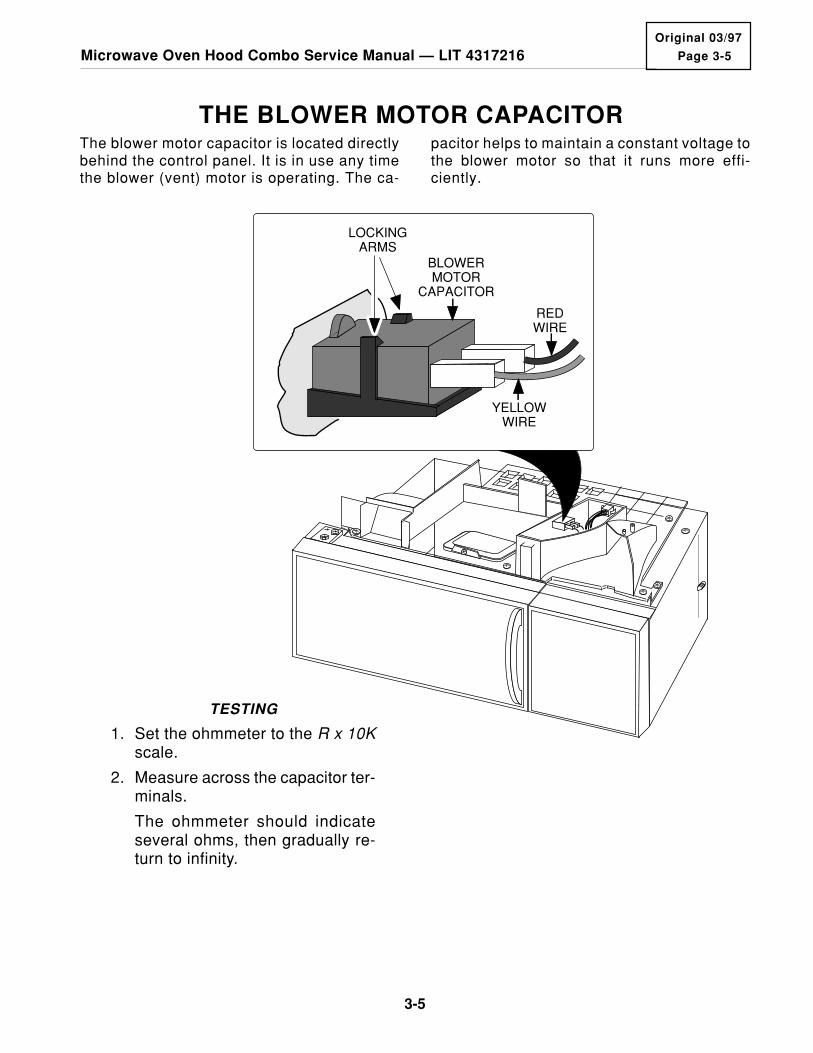
THE BLOWER MOTOR CAPACITOR
TESTING
1. Set the ohmmeter to the R x 10Kscale.
2. Measure across the capacitor ter-minals.
The ohmmeter should indicateseveral ohms, then gradually re-turn to infinity.
The blower motor capacitor is located directlybehind the control panel. It is in use any timethe blower (vent) motor is operating. The ca-
pacitor helps to maintain a constant voltage tothe blower motor so that it runs more effi-ciently.
BLOWERMOTOR
CAPACITOR
REDWIRE
YELLOWWIRE
LOCKINGARMS
3-6
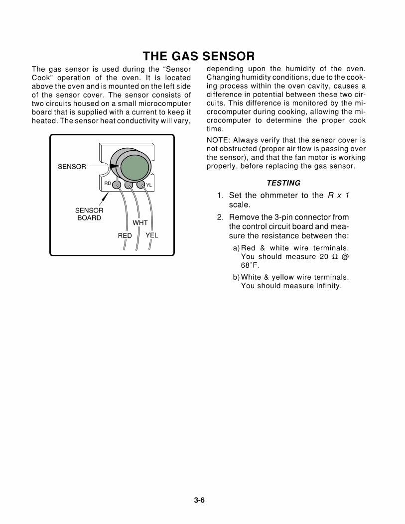
THE GAS SENSOR
TESTING
1. Set the ohmmeter to the R x 1scale.
2. Remove the 3-pin connector fromthe control circuit board and mea-sure the resistance between the:
a) Red & white wire terminals.You should measure 20 Ω @68˚F.
b) White & yellow wire terminals.You should measure infinity.
The gas sensor is used during the “SensorCook” operation of the oven. It is locatedabove the oven and is mounted on the left sideof the sensor cover. The sensor consists oftwo circuits housed on a small microcomputerboard that is supplied with a current to keep itheated. The sensor heat conductivity will vary,
depending upon the humidity of the oven.Changing humidity conditions, due to the cook-ing process within the oven cavity, causes adifference in potential between these two cir-cuits. This difference is monitored by the mi-crocomputer during cooking, allowing the mi-crocomputer to determine the proper cooktime.
NOTE: Always verify that the sensor cover isnot obstructed (proper air flow is passing overthe sensor), and that the fan motor is workingproperly, before replacing the gas sensor.
RDWH
YL
RED
WHT
YEL
SENSOR
SENSORBOARD

Page 3-7
3-7
Microwave Oven Hood Combo Service Manual — LIT 4317216Original 03/97
thermistor signal going back to the microcom-puter causes the heater relay to open andclose, and cycles the heating element on andoff.
NOTE: Verify that the heating element is work-ing correctly before replacing a thermistor.
The convection thermistor is located underthe circulation pulley cover and is used duringthe convection operation of the oven. Whenthe temperature increases, the resistance ofthe thermistor decreases. The thermistor re-sistance is monitored by the microcomputer.As the oven temperature rises and falls, the
THE CONVECTION THERMISTOR
PHILLIPSSCREW
SENSORCOVER
CONVECTIONTHERMISTOR
BRACKETS
CIRCULATIONPULLEY COVER
TESTING
1. Set the ohmmeter to the R x 10Kscale.
2. Remove the 6-pin connector fromthe control circuit board and mea-sure across terminals 5 & 6.
You should measure 155 kΩ to350 kΩ @ 68˚F.

3-8
THE CONVECTION HEATING ELEMENTand the heater relay on the microcomputerboard. During a convection, or combinationcooking cycle, the heater cycles on and off tomaintain the programmed cavity temperature.The heating element surrounds the convec-tion fan blade and is not visible through theoven cavity.
The 1400-watt convection heating element islocated under the circulation pulley cover andthe top plate. The heating element heats theair that is distributed into the oven cavity bythe convection fan. It operates on 120 VACand is controlled by the convection thermistor,
TESTING
1. Set the ohmmeter to the R x 1scale.
2. Measure across the heating ele-ment terminals.
You should measure between40 Ω and 90 Ω @ 68˚F.
CONVECTIONTHERMISTOR
BRACKETS
CIRCULATIONPULLEY COVER
TOP PLATE
CONVECTIONHEATINGELEMENT
YELLOWWIRES
UNCLIPELEMENT
HERE
HEATING ELEMENT
HEATING ELEMENTMOUNTING SCREWS
VIEWED FROM UNDERTOP PLATE
SENSORCOVER
Page 3-9
3-9
Microwave Oven Hood Combo Service Manual — LIT 4317216Original 03/97
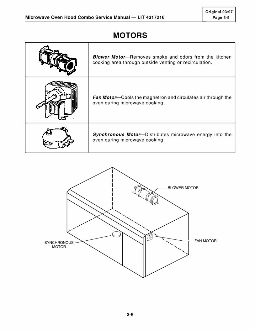
BLOWER MOTOR
FAN MOTORSYNCHRONOUSMOTOR
Blower Motor—Removes smoke and odors from the kitchencooking area through outside venting or recirculation.
Synchronous Motor—Distributes microwave energy into theoven during microwave cooking.
Fan Motor—Cools the magnetron and circulates air through theoven during microwave cooking.
MOTORS
3-10
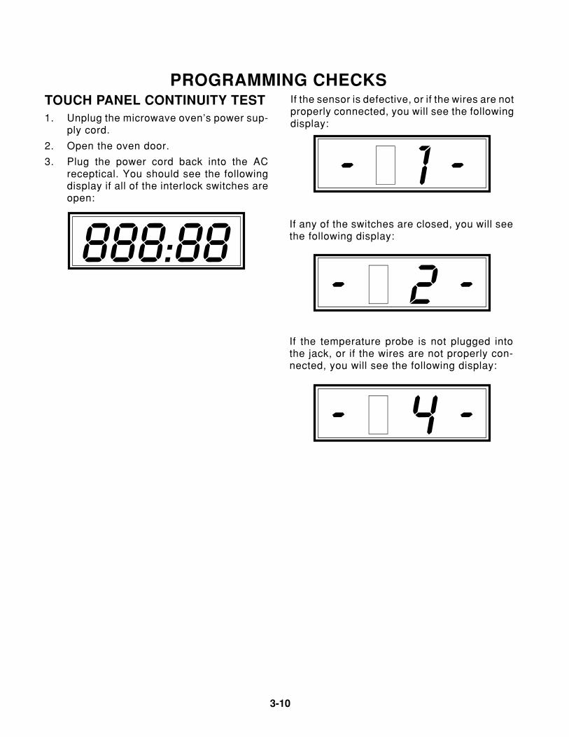
PROGRAMMING CHECKS
If any of the switches are closed, you will seethe following display:
– f 2 –
– f 1 –
If the sensor is defective, or if the wires are notproperly connected, you will see the followingdisplay:
TOUCH PANEL CONTINUITY TEST1. Unplug the microwave oven’s power sup-
ply cord.
2. Open the oven door.
3. Plug the power cord back into the ACreceptical. You should see the followingdisplay if all of the interlock switches areopen:
888:88
If the temperature probe is not plugged intothe jack, or if the wires are not properly con-nected, you will see the following display:
– f 4 –
Page 3-11
3-11
Microwave Oven Hood Combo Service Manual — LIT 4317216Original 03/97
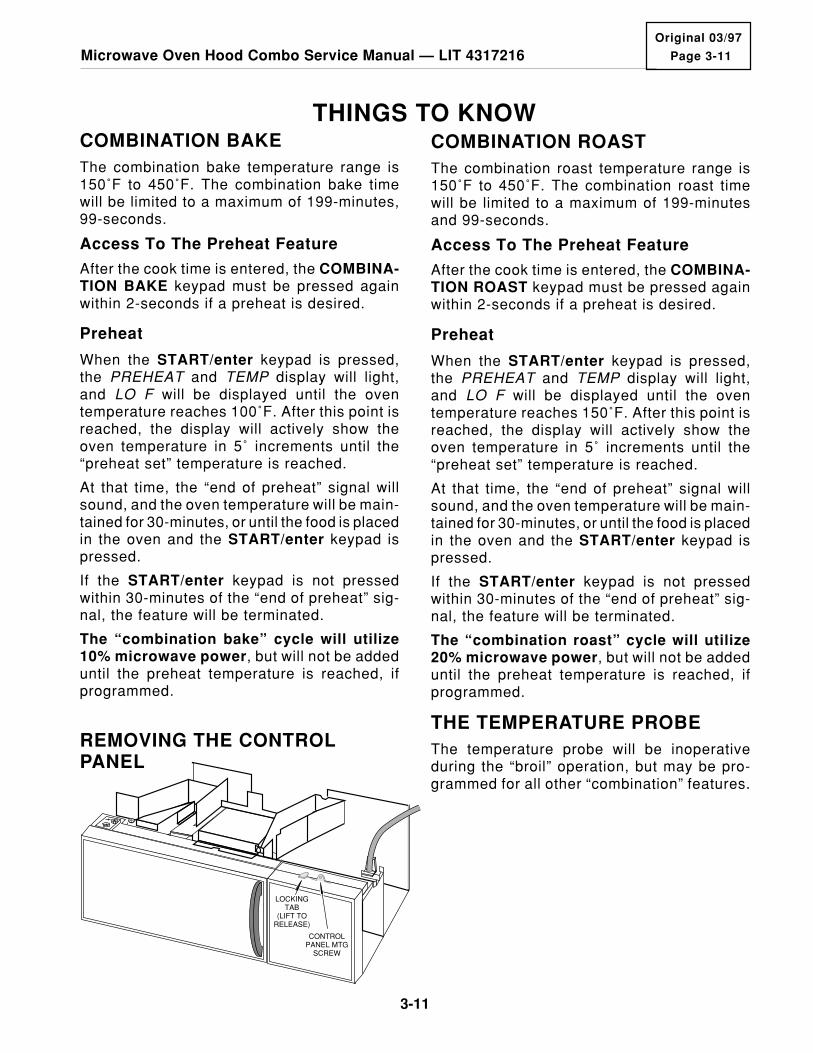
CONTROLPANEL MTG
SCREW
LOCKINGTAB
(LIFT TORELEASE)
REMOVING THE CONTROLPANEL
THINGS TO KNOWCOMBINATION BAKEThe combination bake temperature range is150˚F to 450˚F. The combination bake timewill be limited to a maximum of 199-minutes,99-seconds.
Access To The Preheat Feature
After the cook time is entered, the COMBINA-TION BAKE keypad must be pressed againwithin 2-seconds if a preheat is desired.
Preheat
When the START/enter keypad is pressed,the PREHEAT and TEMP display will light,and LO F will be displayed until the oventemperature reaches 100˚F. After this point isreached, the display will actively show theoven temperature in 5˚ increments until the“preheat set” temperature is reached.
At that time, the “end of preheat” signal willsound, and the oven temperature will be main-tained for 30-minutes, or until the food is placedin the oven and the START/enter keypad ispressed.
If the START/enter keypad is not pressedwithin 30-minutes of the “end of preheat” sig-nal, the feature will be terminated.
The “combination bake” cycle will utilize10% microwave power, but will not be addeduntil the preheat temperature is reached, ifprogrammed.
COMBINATION ROASTThe combination roast temperature range is150˚F to 450˚F. The combination roast timewill be limited to a maximum of 199-minutesand 99-seconds.
Access To The Preheat Feature
After the cook time is entered, the COMBINA-TION ROAST keypad must be pressed againwithin 2-seconds if a preheat is desired.
Preheat
When the START/enter keypad is pressed,the PREHEAT and TEMP display will light,and LO F will be displayed until the oventemperature reaches 150˚F. After this point isreached, the display will actively show theoven temperature in 5˚ increments until the“preheat set” temperature is reached.
At that time, the “end of preheat” signal willsound, and the oven temperature will be main-tained for 30-minutes, or until the food is placedin the oven and the START/enter keypad ispressed.
If the START/enter keypad is not pressedwithin 30-minutes of the “end of preheat” sig-nal, the feature will be terminated.
The “combination roast” cycle will utilize20% microwave power, but will not be addeduntil the preheat temperature is reached, ifprogrammed.
THE TEMPERATURE PROBEThe temperature probe will be inoperativeduring the “broil” operation, but may be pro-grammed for all other “combination” features.

3-12
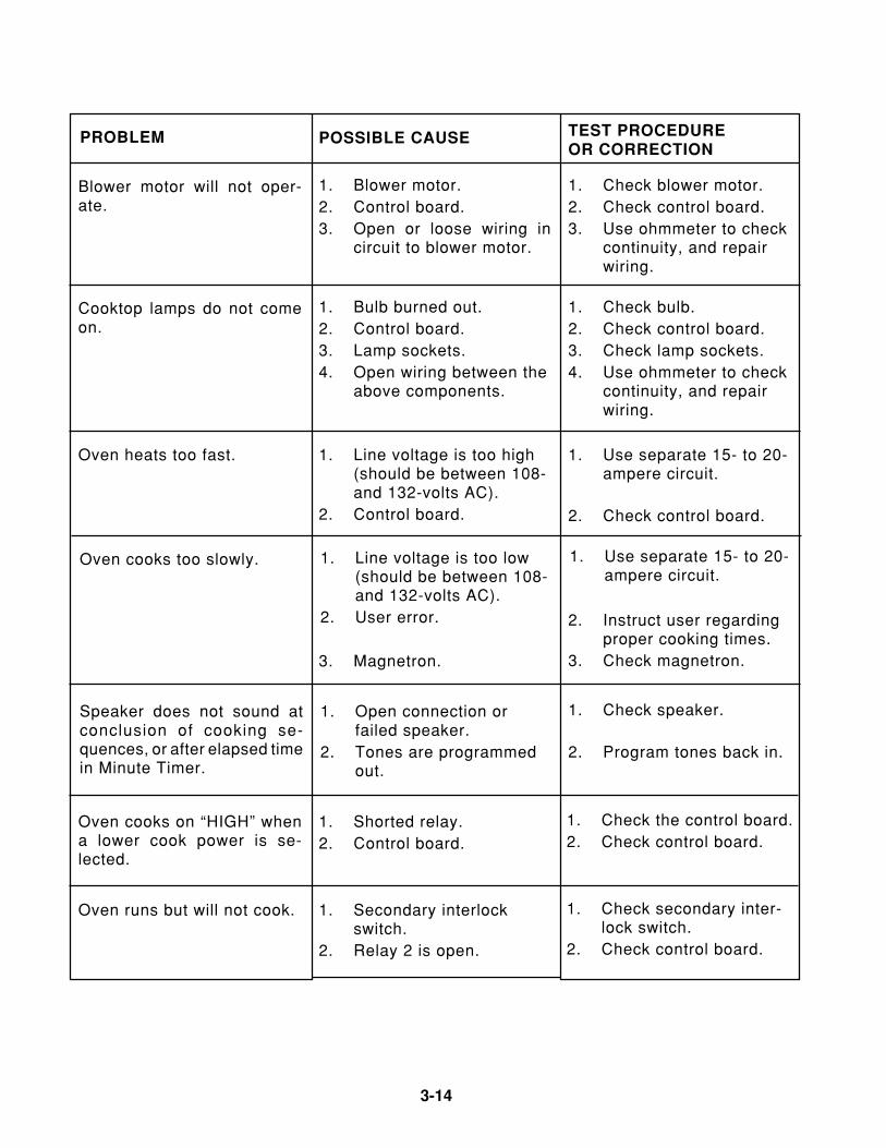
CHARTSTEST PROCEDUREOR CORRECTION
Shorted wire in power cord,wiring harness, or overloadcircuit.
Line fuse blows when powercord is plugged into a wallreceptacle.
1. Check wiring with ohm-meter for continuity.
2. Use separate 15- to 20-ampere circuit.
1. No power at wall plug. 1. Check fuse or breakerbox.
2. Check wiring with ohm-meter for continuity.
3. Check board.4. Check fuse.5. Check fuse.
Oven will not operate.
Oven cavity light will not turnon.
1. Bulb is burned out.2. Lamp socket.3. Oven lamp switch.4. Open wiring between the
above components.
1. Replace bulb.2. Check lamp socket.3. Check control board.4. Repair open wire.
1. Check control board.2. Check line fuse and/or
thermal fuses.3. Check interlockswitches.4. Repair open wire.
1. Control board.2. Line fuse and/or thermal
fuses.3. Interlock switches.4. Open wiring between the
above components.
Oven will not go into “Cook”cycle when the door is closed.
1. Check control board.2. Use separate 15- to 20-
ampere circuit.
1. Control board.2. Low line voltage (should
be at least 108-voltsAC).
3. Thermal fuse.4. Thermal fuse on magne-
tron.5. Circuit is overloaded.
Oven goes into “Cook” cycle,but does not complete thecycle. Heat is produced in theoven load.
PROBLEM POSSIBLE CAUSE
2. Open wire in power cordor wiring harness.
3. Control board.4. Line fuse.5. Thermal fuses.
3. Check thermal fuse.4. Check thermal fuse on
magnetron.5. Use separate 15- to 20-
ampere circuit.

Page 3-13
3-13
Microwave Oven Hood Combo Service Manual — LIT 4317216Original 03/97
TEST PROCEDUREOR CORRECTION
1. High voltage transformer.Little or no heat is producedin the oven load.
1. Check the high voltagetransformer.
2. Check the high voltagerectifier diode.
3. Check the high voltagecapacitor.
4. Check the magnetron.5. Check the power selec-
tor.
1. Primary interlock switch. 1. Check primary interlockswitch.
2. Repair wiring.
Oven fuse blows when thedoor is opened.
Oven lamp goes on with thedoor open, but the light goesout when the door is closedwith the control on.
1. Secondary interlock. 1. Check secondary inter-lock.
The power source fuse blowswhen the door starts to open.
1. High voltage trans-former.
2. Secondary circuit of thehigh voltage transformeris shorted.
3. High voltage capacitor isshorted.
4. Shorted wiring betweenthe above components.
1. Check the high voltagetransformer.
2. Check the high voltagetransformer.
PROBLEM POSSIBLE CAUSE
3. Check the high voltagecapacitor.
4. Use an ohmmeter tocheck continuity, andrepair wiring.
5. Check blower motor.5. Blower motor.
1. Fan motor.2. Open or loose wiring in
circuit to fan motor.
Fan motor will not operate. 1. Check fan motor.2. Use ohmmeter to check
continuity, and repairwiring.
2. Shorted wire harness.
2. Rectifier diode.
3. High voltage capacitor.
4. Magnetron.5. Power selector.
3-14
TEST PROCEDUREOR CORRECTION
1. Blower motor.2. Control board.3. Open or loose wiring in
circuit to blower motor.
Blower motor will not oper-ate.
1. Check blower motor.2. Check control board.3. Use ohmmeter to check
continuity, and repairwiring.
1. Bulb burned out.2. Control board.3. Lamp sockets.4. Open wiring between the
above components.
1. Check bulb.2. Check control board.3. Check lamp sockets.4. Use ohmmeter to check
continuity, and repairwiring.
Cooktop lamps do not comeon.
Oven heats too fast. 1. Line voltage is too high(should be between 108-and 132-volts AC).
2. Control board.
1. Use separate 15- to 20-ampere circuit.
PROBLEM POSSIBLE CAUSE
Oven cooks too slowly. 1. Line voltage is too low(should be between 108-and 132-volts AC).
2. User error.
1. Use separate 15- to 20-ampere circuit.
2. Instruct user regardingproper cooking times.
3. Check magnetron.
2. Check control board.
1. Secondary interlockswitch.
2. Relay 2 is open.
1. Check secondary inter-lock switch.
2. Check control board.
1. Open connection orfailed speaker.
2. Tones are programmedout.
Speaker does not sound atconclusion of cooking se-quences, or after elapsed timein Minute Timer.
1. Check speaker.
1. Shorted relay.2. Control board.
Oven cooks on “HIGH” whena lower cook power is se-lected.
1. Check the control board.2. Check control board.
Oven runs but will not cook.
2. Program tones back in.
3. Magnetron.
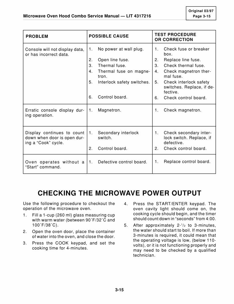
Page 3-15
3-15
Microwave Oven Hood Combo Service Manual — LIT 4317216Original 03/97
TEST PROCEDUREOR CORRECTION
1. No power at wall plug.Console will not display data,or has incorrect data.
1. Check fuse or breakerbox.
2. Replace line fuse.3. Check thermal fuse.4. Check magnetron ther-
mal fuse.5. Check interlock safety
switches. Replace, if de-fective.
6. Check control board.
PROBLEM POSSIBLE CAUSE
2. Open line fuse.3. Thermal fuse.4. Thermal fuse on magne-
tron.5. Interlock safety switches.
6. Control board.
1. Magnetron. 1. Check magnetron.Erratic console display dur-ing operation.
Display continues to countdown when door is open dur-ing a “Cook” cycle.
1. Secondary interlockswitch.
1. Check secondary inter-lock switch. Replace, ifdefective.
2. Check control board.
Oven operates wi thout a“Start” command.
1. Defective control board. 1. Replace control board.
2. Control board.
Use the following procedure to checkout theoperation of the microwave oven.
1. Fill a 1-cup (260 ml) glass measuring cupwith warm water (between 90˚F/32˚C and100˚F/38˚C).
2. Open the oven door, place the containerof water into the oven, and close the door.
3. Press the COOK keypad, and set thecooking time for 4-minutes.
4. Press the START/ENTER keypad. Theoven cavity light should come on, thecooking cycle should begin, and the timershould count down in “seconds” from 4:00.
5. After approximately 2-1/2 to 3-minutes,the water should start to boil. If more than3-minutes is required, it could mean thatthe operating voltage is low, (below 110-volts), or it is not functioning properly andmay need to be checked by a qualifiedtechnician.
CHECKING THE MICROWAVE POWER OUTPUT

3-16
CHECKING FOR MICROWAVE ENERGY LEAKAGE
CAUTIONOn every service call, checks for microwaveenergy emission must be made according tothe following manner.
1. Remove the cooking rack from the ovencavity, i f the microwave oven is soequipped.
2. Place a 275 ML (9. oz.) glass of water inthe center of the oven bottom.
3. Select “HlGH” cook power, turn the mi-crowave oven on, and test for R.F. Ieakageusing the following pattern:
a) Check around the cabinet at the front.
b) Check around the door.
c) Check across the console panel.
d) Check horizontally across the door
e) Check vertically across the door.
f) Check diagonally across the door.
g) Check across the air vents.
h) Check across the rear air vent.
NOTE: The scan speed is one-inch-per-sec-ond.
When checking for R.F. Ieakage, use an ap-proved R.F. measuring device to assure lessthan 4 mw/cm2 emission at 5 cm distance witha maximum scan rate of 2.5 cm/second, incompliance with U.S. Government Departmentof Health, Education and Welfare 21 CFR1030,performance Standard for Microwave Ovens.
A properly operating door and seal assemblywill normally register small emissions, but theymust be no greater than 4 mw/cm2 to allow formeasurement uncertainty.
NOTE: Enter leakage readings in the spaceBEFORE and AFTER on the service docu-ment.
All microwave ovens exceeding the emissionlevel of 4 mw/cm2 must be reported to Dept. ofService for microwave ovens immediately andthe owner should be told not to use the micro-wave oven until it has been repaired com-pletely.
If a microwave oven is found to operate withthe door open, report to Dept. of Service, themanufacturer, and CDRH* immediately. Alsotell the owner not to use the oven.
The interlock monitor switch acts as the finalsafety switch protecting the customer frommicrowave radiation. If the interlock monitorswitch operates and opens the line fuse, theinterlock switches have failed, and you mustreplace all of them (primary and secondaryinterlock switches, and the monitor switch),because their contacts may be melted andwelded together.
All repairs must be performed so that micro-wave energy emissions are minimal.
* CDRH: Center for Device and Radiological health, food, and drug administration.
EQUIPMENT• Electromagnetic energy leakage monitor
(NARDA 8100B, HOLADAY H1501).
• 6100 cc glass beaker.
• Glass thermometer 100˚C or 212˚F.
Page 3-17
3-17
Microwave Oven Hood Combo Service Manual — LIT 4317216Original 03/97
MAKING THE MEASUREMENTSMeasuring The Oven With TheCabinet Installed
MEASUREMENT NOTES:
• When measuring for leakage, use the 2"(5 cm ) spacer that is provided with theprobe.
• Leakage with the outer panels removedshould be less than 5 mW/cm.sq.
• Leakage for a fully assembled oven (beforethe lamp switch primary is interrupted) withthe door opened slightly, should be lessthan 2 mW/cm.sq.
• Do not exceed the meter’s full-scale deflec-tion.
• Do not move the test probe along the mea-suring surfaces faster than 1-inch-per-sec-ond (2.5 cm/sec), otherwise a false readingwill occur.
• When testing near a corner of the door,keep the probe perpendicular to the sur-face, and move it horizontally without touch-ing the surfaces, otherwise a false readingwill occur.
• Hold the test probe by its gripping surfaceonly, otherwise a false reading will occur.
To measure for oven leakage:
1. Pour 275 (±25cc) of water into a 600 ccgraduated beaker.
2. Place the beaker into the center of themicrowave oven.
3. Set the energy leakage monitor to 2,450MHz, and use i t accord ing to themanufacturer’s recommended test pro-cedure to obtain the correct results.
4. Measure the microwave radiation with anelectromagnetic radiation monitor. Holdthe probe perpendicular to the surfacebeing measured, and measure aroundthe door viewing window, the exhaustopening, and air inlet openings.
5. Operate the oven at its maximum energyoutput, and take the measurements.
Measuring The Oven With TheCabinet Removed
When the magnetron has been replaced, usethe previous procedure, and measure for mi-crowave energy leakage after all of the neces-sary components are replaced or adjusted,and before the cabinet is installed. Take spe-cial care to measure around the magnetronand the waveguide. WARNING: Be carefulnot to contact any of the high voltage com-ponents when making measurements withthe cabinet removed.

3-18
MEASURING MICROWAVEPOWER OUTPUT USING THEIEC-705 RATING STANDARDWhen determining the microwave oven’s poweroutput using the IEC-705 rating standard, thefollowing conditions must be met:
• When making microwave power output mea-surements, the oven is supplied with itsrated line voltage, and operated at its maxi-mum power output setting with a load of1000 (±5) cc of potable water.
• The water is contained in a cylindrical boro-silicate glass vessel having a maximummaterial thickness of 1/8" and an outsidediameter of approximately 7.6".
• The oven and the empty vessel are at ambi-ent temperature prior to the start of the test.
• The initial temperature of the water is 10˚C±2˚ (50˚F). It is measured immediately be-fore the water is added to the vessel. Afteraddition of the water to the vessel, the loadis immediately placed on the center of theshelf, which is in the lowest position, andthe microwave power switched on.
• The time (in seconds) for the temperature ofthe water to rise by a value of 10˚C ±2˚ ismeasured. The initial and final water tem-peratures are selected so that the maximumdifference between the final water tempera-ture, and the ambient temperature, is 5˚C.
• The microwave power output (in watts) iscalculated, using the following formula:
(L) 4187 (∆T)
T1 P =
L = time (in seconds).
P = microwave output power.
(∆T) = temperature rise.
• Microwave power output is measured withthe oven operating at full power. The mag-netron filament heat-up time (approximately2-seconds) is not included.
• The water is stirred to equalize the tempera-ture throughout the vessel, prior to measur-ing the final water temperature.
• Stirring devices and measuring instrumentsare selected to minimize the addition orremoval of heat.
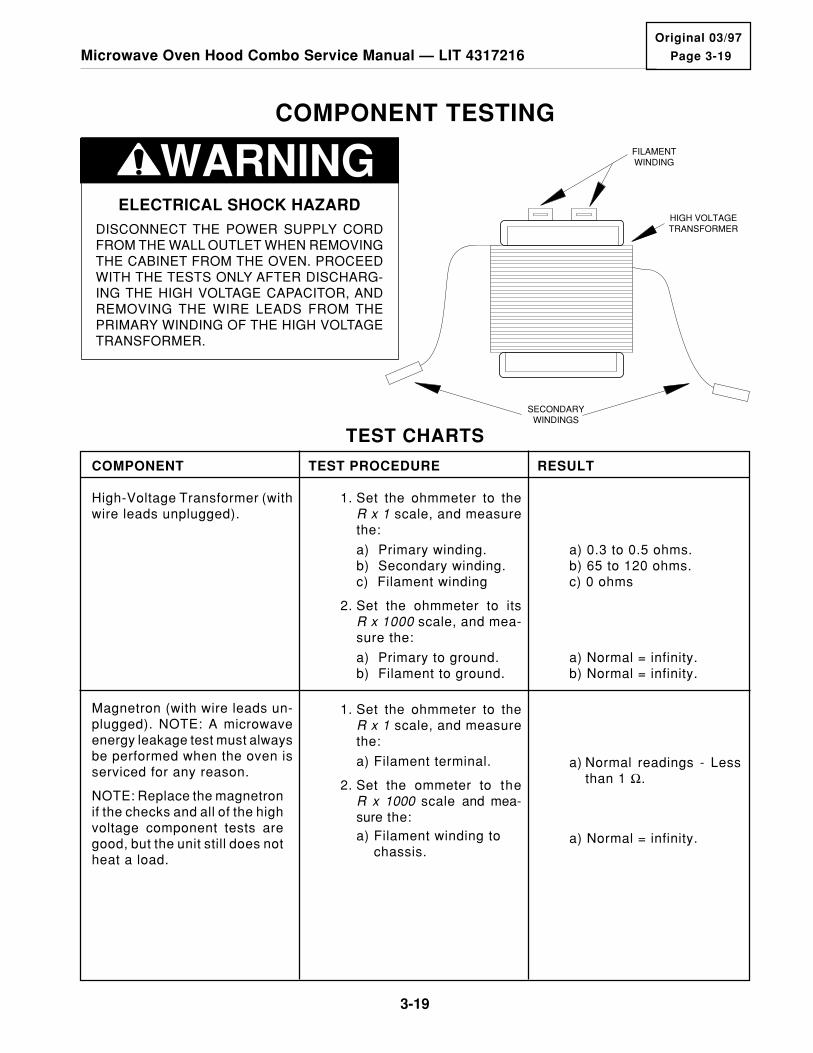
Page 3-19
3-19
Microwave Oven Hood Combo Service Manual — LIT 4317216Original 03/97
TEST CHARTS
TEST PROCEDURE RESULTCOMPONENT
1. Set the ohmmeter to theR x 1 scale, and measurethe:
a) Primary winding.b) Secondary winding.c) Filament winding
2. Set the ohmmeter to itsR x 1000 scale, and mea-sure the:
a) Primary to ground.b) Filament to ground.
Magnetron (with wire leads un-plugged). NOTE: A microwaveenergy leakage test must alwaysbe performed when the oven isserviced for any reason.
1. Set the ohmmeter to theR x 1 scale, and measurethe:
a) Filament terminal.
2. Set the ommeter to theR x 1000 scale and mea-sure the:a) Filament winding to chassis.
a) Normal readings - Lessthan 1 Ω.
a) Normal = infinity.
High-Voltage Transformer (withwire leads unplugged).
a) 0.3 to 0.5 ohms.b) 65 to 120 ohms.c) 0 ohms
a) Normal = infinity.b) Normal = infinity.
NOTE: Replace the magnetronif the checks and all of the highvoltage component tests aregood, but the unit still does notheat a load.
COMPONENT TESTING
WARNINGELECTRICAL SHOCK HAZARD
DISCONNECT THE POWER SUPPLY CORDFROM THE WALL OUTLET WHEN REMOVINGTHE CABINET FROM THE OVEN. PROCEEDWITH THE TESTS ONLY AFTER DISCHARG-ING THE HIGH VOLTAGE CAPACITOR, ANDREMOVING THE WIRE LEADS FROM THEPRIMARY WINDING OF THE HIGH VOLTAGETRANSFORMER.
FILAMENTWINDING
SECONDARYWINDINGS
HIGH VOLTAGETRANSFORMER

3-20
TEST PROCEDURE RESULTCOMPONENT
Terminal-To-Terminal
Set the ohmmeter to the R x 10 kscale, and measure the resistanceacross the capacitor terminals.
High-Voltage Capacitor a) Normal - The meter indi-cates several ohms, thengradually returns to in-finity.
b) Abnormal - The meterindicates infinity, or zeroohms (a short) immedi-ately.
Terminal-To-Case
Set the ohmmeter to the R x 1scale, and measure the resistancebetween each terminal and thecase.
a) Normal - The meter indi-cates infinity.
b) Abnormal - The meterindicates zero ohms, ora short.
Blower Motor Capacitor Terminal-To-Terminal
Set the ohmmeter to the R x 10 kscale, and measure the resistanceacross the capacitor terminals.
a) Normal - The meter indi-cates several ohms, thengradually returns to in-finity.
b) Abnormal - The meterindicates infinity, or zeroohms (a short) immedi-ately.
a) Normal - The meter indi-cates several ohms.
b) Abnormal - The meterindicates infinity, or zeroohms (a short).
Forward Continuity
Set the ohmmeter to the R x 1scale, and measure the forwardresistance across the rectifier ter-minals with the (+) lead touchingthe anode and the (–) lead touch-ing the cathode.
High-Voltage Rectifier
a) Normal - The meter indi-cates infinity.
b) Abnormal - The meterindicates infinity, or zeroohms (a short).
Reverse Continuity
Set the ohmmeter to its highestscale, and measure the reverseresistance across the rectifier ter-minals with the (+) lead touchingthe cathode and the (–) lead touch-ing the anode.
CAPACITOR
CATHODE
ANODE
RECTIFIERDIODE

Page 3-21
3-21
Microwave Oven Hood Combo Service Manual — LIT 4317216Original 03/97
Ambient ResistanceTemp. (˚F) Value
60 75.24 kΩ (±11 kΩ)
68 62.57 kΩ (±8 kΩ)
70 59.79 kΩ (±8 kΩ)
80 45.80 kΩ (±7 kΩ)
90 36.94 kΩ (±6 kΩ)
TEST PROCEDURE RESULTCOMPONENT
N.O. and C Terminals
Set the ohmmeter to the R x 1scale, and measure the resistancebetween the normally-open (N.O.)and the common (C) terminals ofthe switch.
Switches (with wire leads re-moved). All of the switches aremeasured in the same manner.
Temperature Probe Set the ohmmeter to the R x 10 kscale, and measure the tempera-ture probe with the leads posi-tioned at either terminal.
a) Fan Motor - Normal = 30to 45 ohms.
Set the ohmmeter to the R x 1scale, and measure across theterminals.
a) Normal - The meter indi-cates infinity.
b) Abnormal - The meterindicates zero ohms (ashort).
N.C. and C Terminals
Set the ohmmeter to the R x 1scale, and measure the resistancebetween the normal ly-c losed(N.C.) and the common (C) termi-nals of the switch.
b) Abnormal - The meterindicates infinity.
a) Normal - The meter indi-cates continuity, or zeroohms.
Fan Motor (with leads discon-nected).
Blower Motor (with leads dis-connected)
Set the ohmmeter to the R x 1scale, and measure the:
a) High speed windings (blue and black wires).
b) Low speed windings (blue and white wires).
a) Normal - High speed: 25to 45 ohms.
b) Normal - Low speed: 45to 65 ohms.
a) Normal - 3 k to 4 k ohms.
b) Abnormal - Infinite orzero ohms.
Set the ohmmeter to the R x 1000scale, and measure the resistancebetween the motor terminals.
Synchronous Motor (with leadsdisconnected)
C.N.C. CONTACTS
N.O. CONTACTS

3-22
TEST PROCEDURE RESULTCOMPONENT
a) Normal = 155 K to 350 Kohms @ 68˚F.
Set the ohmmeter to the R x 10 Kscale.
Remove the 6-pin connector fromthe circuit board and measureacross terminals 5 & 6.
b) Abnormal = Infinity, orzero ohms (a short).
Convection Thermistor
Set the ohmmeter to the R x 1scale, and measure across theterminals.
Convection Heating Element(with leads disconnected)
a) Normal = 9 to 40 ohms @68˚F ±2˚.
b) Abnormal = Infinity, orzero ohms (a short).
Set the ohmmeter to the R x 1scale.
Remove the 3-pin connector fromthe circuit board and measure theresistance between:
a) Red & white wire terminals.
b) White & yellow wire terminals.
Gas Sensor
b) Infinite.
a) 20 ohms @ 68˚F ±2˚.
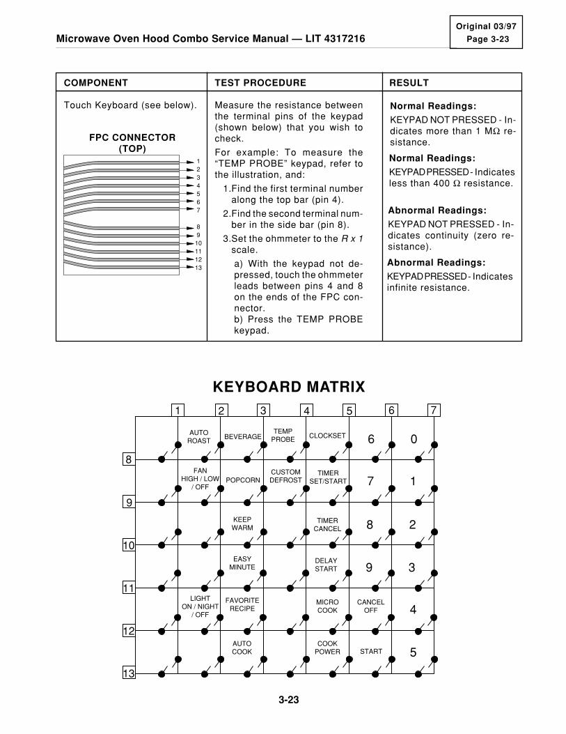
Page 3-23
3-23
Microwave Oven Hood Combo Service Manual — LIT 4317216Original 03/97
TEST PROCEDURE RESULTCOMPONENT
Touch Keyboard (see below). Measure the resistance betweenthe terminal pins of the keypad(shown below) that you wish tocheck.
For example: To measure the“TEMP PROBE” keypad, refer tothe illustration, and:
1.Find the first terminal numberalong the top bar (pin 4).
2.Find the second terminal num-ber in the side bar (pin 8).
3.Set the ohmmeter to the R x 1scale.
a) With the keypad not de-pressed, touch the ohmmeterleads between pins 4 and 8on the ends of the FPC con-nector.b) Press the TEMP PROBEkeypad.
Normal Readings:
KEYPAD NOT PRESSED - In-dicates more than 1 MΩ re-sistance.
Normal Readings:
KEYPAD PRESSED - Indicatesless than 400 Ω resistance.
Abnormal Readings:
KEYPAD NOT PRESSED - In-dicates continuity (zero re-sistance).
Abnormal Readings:
KEYPAD PRESSED - Indicatesinfinite resistance.
1234567
89
10111213
FPC CONNECTOR(TOP)
AUTOROAST
BEVERAGETEMP
PROBE
CUSTOMDEFROST
CLOCKSET 6 0
7 1
8 2
9 3
4
5
FANHIGH / LOW
/ OFFPOPCORN
TIMERSET/START
KEEPWARM
EASYMINUTE
FAVORITERECIPE
TIMERCANCEL
DELAYSTART
LIGHTON / NIGHT
/ OFF
MICROCOOK
COOKPOWER
AUTOCOOK
CANCELOFF
START
1 2 3 4 5 6 7
8
9
10
11
12
13
KEYBOARD MATRIX
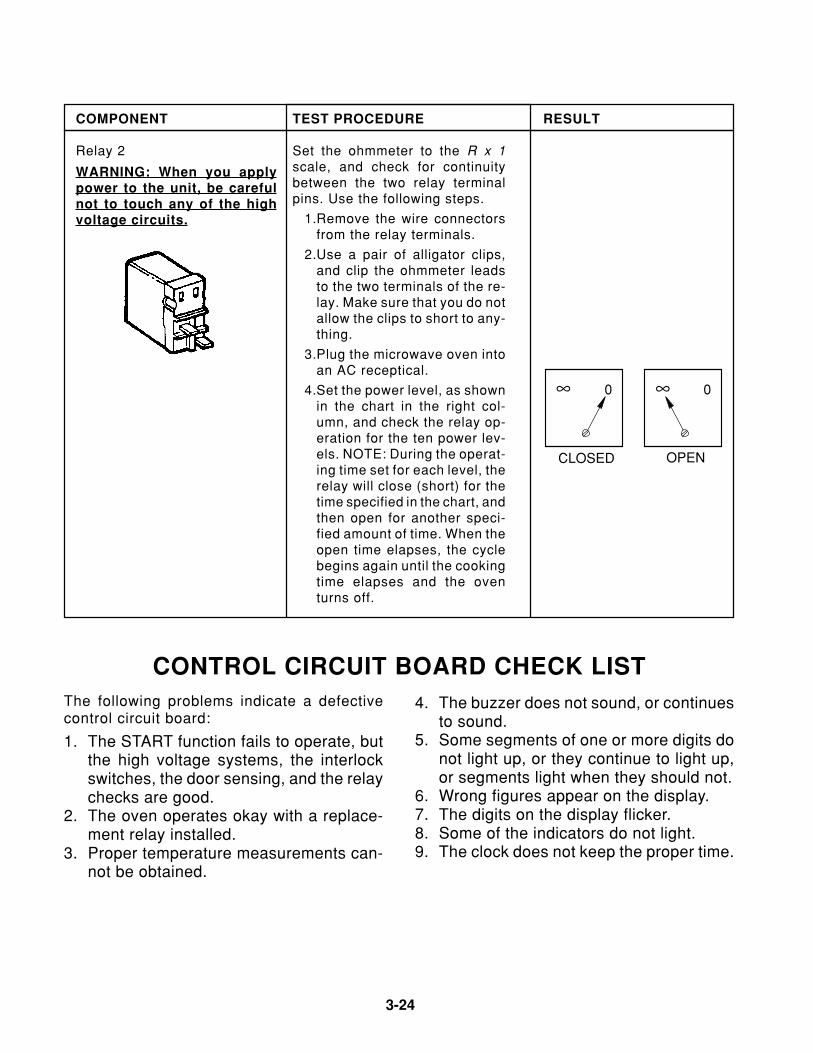
3-24
TEST PROCEDURE RESULTCOMPONENT
Relay 2
WARNING: When you applypower to the unit, be carefulnot to touch any of the highvoltage circuits.
Set the ohmmeter to the R x 1scale, and check for continuitybetween the two relay terminalpins. Use the following steps.
1.Remove the wire connectorsfrom the relay terminals.
2.Use a pair of alligator clips,and clip the ohmmeter leadsto the two terminals of the re-lay. Make sure that you do notallow the clips to short to any-thing.
3.Plug the microwave oven intoan AC receptical.
4.Set the power level, as shownin the chart in the right col-umn, and check the relay op-eration for the ten power lev-els. NOTE: During the operat-ing time set for each level, therelay will close (short) for thetime specified in the chart, andthen open for another speci-fied amount of time. When theopen time elapses, the cyclebegins again until the cookingtime elapses and the oventurns off.
CONTROL CIRCUIT BOARD CHECK LISTThe following problems indicate a defectivecontrol circuit board:
1. The START function fails to operate, butthe high voltage systems, the interlockswitches, the door sensing, and the relaychecks are good.
2. The oven operates okay with a replace-ment relay installed.
3. Proper temperature measurements can-not be obtained.
4. The buzzer does not sound, or continuesto sound.
5. Some segments of one or more digits donot light up, or they continue to light up,or segments light when they should not.
6. Wrong figures appear on the display.7. The digits on the display flicker.8. Some of the indicators do not light.9. The clock does not keep the proper time.
∞ 00
OPENCLOSED
∞

Page 3-25
3-25
Microwave Oven Hood Combo Service Manual — LIT 4317216Original 03/97
PRIMARY, MONITOR, & SECONDARY SWITCHCHECKOUT PROCEDURE
L1
RELAY#2
SECONDARYINTERLOCK
SWITCH
OVEN LIGHTSSWITCH
MONITORSWITCH
N.C.N.O.C
N
DOOR CLOSED
DOOR OPEN
L1
RELAY#2
SECONDARYINTERLOCK
SWITCH
OVEN LIGHTSSWITCH
MONITORSWITCH
N.C.N.O.C
N
NOTE: The following chart and strip circuits show the continuity and position of the door switcheswhen the microwave oven door is open and closed.
SWITCH TESTINGDOOROPEN
DOORCLOSED
PrimaryInterlock
Disconnect the 4-pin connector from the control module. Check from the pink wire (pin 1) to the blue wire (pin 3). – +
SecondaryInterlock
Disconnect the wires at the Secondary Interlock Switch. Check from the common terminal (white wires) to the normally-open terminal (red/white wires).
– +
MonitorDisconnect the wires from the Monitor Switch. Check from the common terminal (red/brown wires) to the normally-closed terminal (white wire).
+ –
OvenLamp
Disconnect the wires from the Oven Lamp Switch. Check from the common terminal (blue wire) to the normally-closed terminal (red wire).
+ _
Disconnect the wires from the Oven Lamp Switch. Check from the common terminal (blue wire) to the normally-open terminal (pink/black wire).
– +
(+) = CONTINUITY(–) = NO CONTINUITY
CONTINUITY TEST CHART

3-26
— NOTES —