Embed Size (px)
Citation preview
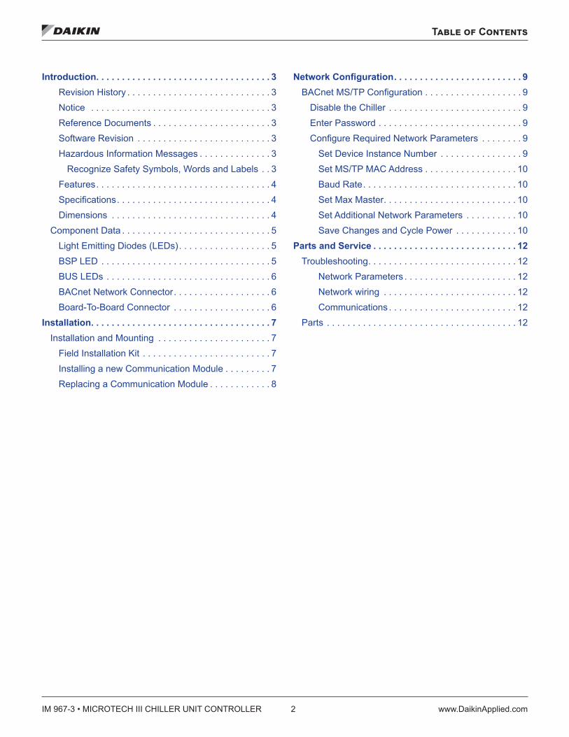
Installation and Maintenance Manual IM 967-3Group: ControlsPart Number: IM 967Date: March 2017
MicroTech® III Chiller BACnet® MS/TP Communication ModuleModels AGZ and AMZ Trailblazer® Air-Cooled Scroll Chiller Models AWS and AWV Pathfinder® Air-Cooled Screw ChillerModel ADS Air-Cooled Global Screw Chiller
IM 967-3 • MICROTECH III CHILLER UNIT CONTROLLER 2 www.DaikinApplied.com
Table of Contents
Table of Contents
Introduction . . . . . . . . . . . . . . . . . . . . . . . . . . . . . . . . . . 3Revision History . . . . . . . . . . . . . . . . . . . . . . . . . . . . 3Notice . . . . . . . . . . . . . . . . . . . . . . . . . . . . . . . . . . . 3Reference Documents . . . . . . . . . . . . . . . . . . . . . . . 3Software Revision . . . . . . . . . . . . . . . . . . . . . . . . . . 3Hazardous Information Messages . . . . . . . . . . . . . . 3
Recognize Safety Symbols, Words and Labels . . 3Features. . . . . . . . . . . . . . . . . . . . . . . . . . . . . . . . . . 4Specifications . . . . . . . . . . . . . . . . . . . . . . . . . . . . . . 4Dimensions . . . . . . . . . . . . . . . . . . . . . . . . . . . . . . . 4
Component Data . . . . . . . . . . . . . . . . . . . . . . . . . . . . . 5Light Emitting Diodes (LEDs). . . . . . . . . . . . . . . . . . 5BSP LED . . . . . . . . . . . . . . . . . . . . . . . . . . . . . . . . . 5BUS LEDs . . . . . . . . . . . . . . . . . . . . . . . . . . . . . . . . 6BACnet Network Connector. . . . . . . . . . . . . . . . . . . 6Board-To-Board Connector . . . . . . . . . . . . . . . . . . . 6
Installation . . . . . . . . . . . . . . . . . . . . . . . . . . . . . . . . . . . 7Installation and Mounting . . . . . . . . . . . . . . . . . . . . . . 7
Field Installation Kit . . . . . . . . . . . . . . . . . . . . . . . . . 7Installing a new Communication Module . . . . . . . . . 7Replacing a Communication Module . . . . . . . . . . . . 8
Network Configuration . . . . . . . . . . . . . . . . . . . . . . . . . 9BACnet MS/TP Configuration . . . . . . . . . . . . . . . . . . . 9
Disable the Chiller . . . . . . . . . . . . . . . . . . . . . . . . . . 9Enter Password . . . . . . . . . . . . . . . . . . . . . . . . . . . . 9Configure Required Network Parameters . . . . . . . . 9
Set Device Instance Number . . . . . . . . . . . . . . . . 9Set MS/TP MAC Address . . . . . . . . . . . . . . . . . . 10Baud Rate. . . . . . . . . . . . . . . . . . . . . . . . . . . . . . 10Set Max Master. . . . . . . . . . . . . . . . . . . . . . . . . . 10Set Additional Network Parameters . . . . . . . . . . 10Save Changes and Cycle Power . . . . . . . . . . . . 10
Parts and Service . . . . . . . . . . . . . . . . . . . . . . . . . . . . 12Troubleshooting. . . . . . . . . . . . . . . . . . . . . . . . . . . . . 12
Network Parameters . . . . . . . . . . . . . . . . . . . . . . 12Network wiring . . . . . . . . . . . . . . . . . . . . . . . . . . 12Communications . . . . . . . . . . . . . . . . . . . . . . . . . 12
Parts . . . . . . . . . . . . . . . . . . . . . . . . . . . . . . . . . . . . . 12
Introduction
www.DaikinApplied.com 3 IM 967-3 • MICROTECH III CHILLER UNIT CONTROLLER
Introduction
This manual contains information regarding the network integration system used with MicroTech® III unit controllers on Daikin Applied chillers. It describes how to install or replace a BACnet® communication module on a MicroTech III chiller unit controller. It also explains how to set network parameters and establish communication between the chiller and BACnet network.
Revision HistoryIM 967 Oct 2009 Initial release
IM 967-1 Mar 2012Updated OM 998 to OM 1051; added AGZ model. Updated Daikin McQuay branding and associated references. Added WTC model. Updated Daikin Applied branding and part number references
IM 967-2 Nov 2016
Formatting and branding refresh, updated Ref Docs table and parts list, added specifications, agency listings, Fig 1-2; updated photos. Added AGZ-E and AWV chiller models. Updated BSP LED functionality for BSP 10.xx, detailed information added to Troubleshooting
IM 967-3 March 2017
Added AMZ chiller model to data tables, Reference Documents, and other associated references.
Notice © 2017 Daikin Applied, Minneapolis MN. All rights reserved throughout the world
Daikin Applied reserves the right to change any information contained herein without prior notice. The user is responsible for determining whether this product is appropriate for his or her application.
™ ® The following are trademarks or registered trademarks of their respective companies: BACnet from American Society of Heating, Refrigerating and Air-Conditioning Engineers, Inc., Daikin Applied, Pathfinder, Trailblazer, and MicroTech III from Daikin Applied.
Reference DocumentsCompany Number Title Source
Daikin Applied IOM 1202Pathfinder® Model AWS Air Cooled Chiller Installation, Operation, and Maintenance Manual
www.DaikinApplied.
com
Daikin Applied IOM 1242 Pathfinder Model AWV Air Cooled Chiller Installation, Operation, and Maintenance Manual
www.DaikinApplied.
com
Daikin Applied IOM 1206Trailblazer® Model AGZ Air Cooled Chiller Installation, Operation and Maintenance Manual
www.DaikinApplied.
com
Daikin Applied IOM 1243Trailblazer Model AMZ Air Cooled Chiller Installation, Operation, and Maintenance Manual
www.DaikinApplied.
com
Daikin Applied ED 15120MicroTech III Chiller Unit Controller Protocol Information, BACnet and LonWorks Networks
www.DaikinApplied.
com
Daikin Applied ED 15122MicroTech III Chiller Unit Controller Implementation Conformance Statement (PICS)
www.DaikinApplied.
comAmerican Society of Heating, Refrig, and Air-Conditioning Engineers
ANSI/ ASHRAE 135-2004
BACnet A Data Communication Protocol for Building Automation and Control Networks
www.ashrae.org
Software RevisionThis document supports BSP (Board Support Package)BACnet communication module firmware version 10.34 and all subsequent versions until otherwise indicated.
Limited WarrantyConsult your local Daikin Applied representative for warranty details. To find your local Daikin Applied representative, go to www.DaikinApplied.com.
Hazardous Information MessagesRecognize Safety Symbols, Words and LabelsThe following symbols and labels are used throughout this manual to indicate immediate or potential hazards. It is the owner and installer’s responsibility to read and comply with all safety information and instructions accompanying these symbols. Failure to heed safety information increases the risk of property damage and/or product damage, serious personal injury or death. Improper installation, operation and maintenance can void the warranty.
CAUTIONCautions indicate potentially hazardous situations, which can result in personal injury or equipment damage if not avoided. Static sensitive components. Can cause equipment damage.Discharge any static electrical charge by touching the bare metal inside the control panel before performing any service work. Never unplug cables, circuit board terminal blocks, or power plugs while power is applied to the panel.
WARNINGWarnings indicate potentially hazardous situations, which can result in property damage, severe personal injury, or death if not avoided.
DANGERDangers indicate a hazardous situation which will result in death or serious injury if not avoided. Electric shock hazard. Can cause personal injury or equipment damage. This equipment must be properly grounded. Connections and service to the MicroTech III Unit Controller must be performed only by personnel knowledgeable in the operation of the equipment being controlled.
NOTICEThis equipment generates, uses and can radiate radio frequency energy and, if not installed and used in accordance with this instruction manual, may cause interference to radio communications. It has been tested and found to comply with the limits for a Class A digital device, pursuant to part 15 of the FCC rules. These limits are designed to provide reasonable protection against harmful interference when the equipment is operated in a commercial environment. Operation of this equipment in a residential area is likely to cause harmful interference in which case the user will be required to correct the interference at his or her own expense. Daikin disclaims any liability resulting from any interference or for the correction thereof.
IM 967-3 • MICROTECH III CHILLER UNIT CONTROLLER 4 www.DaikinApplied.com
Introduction
The BACnet communication module connects the MicroTech III chiller unit controller to a building automation system (BAS). This interface enables the exchange of BACnet objects between the unit controller and the network. The BACnet communication module, together with the unit controller, support the BACnet MS/TP (EIA 485) data link layer (physical layer.)
Features• Integration into a building automation and control system
via BACnet MS/TP (B-AAC profile)• Simple attachment to a MicroTech III chiller unit controller• LEDs that indicate communication status and network
activity• Network parameters configurable via the unit controller,
BAS, or remote HMI• BACnet application pre-installed and ready for custom
configuration • Circuit board components enclosed in protective housing
SpecificationsThe following section provides a summary of technical data and conformance to agency listings.
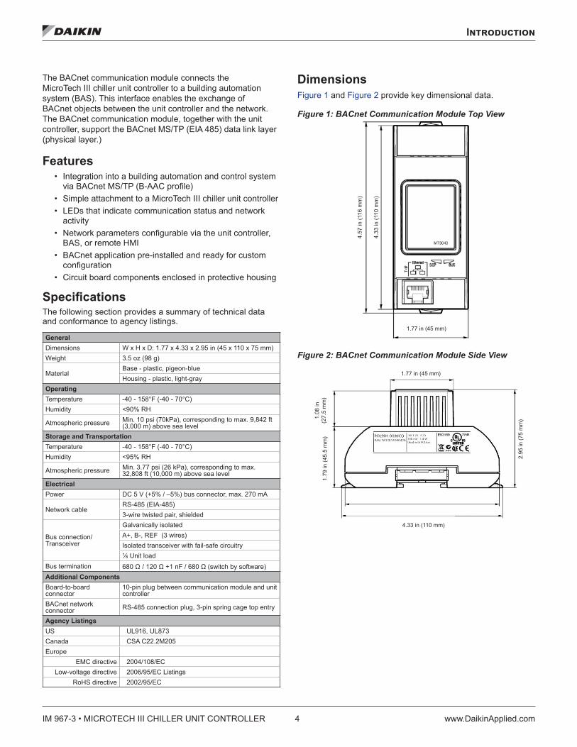
GeneralDimensions W x H x D: 1.77 x 4.33 x 2.95 in (45 x 110 x 75 mm)Weight 3.5 oz (98 g)
MaterialBase - plastic, pigeon-blueHousing - plastic, light-gray
OperatingTemperature -40 - 158°F (-40 - 70°C)Humidity <90% RH
Atmospheric pressure Min. 10 psi (70kPa), corresponding to max. 9,842 ft (3,000 m) above sea level
Storage and TransportationTemperature -40 - 158°F (-40 - 70°C)Humidity <95% RH
Atmospheric pressure Min. 3.77 psi (26 kPa), corresponding to max. 32,808 ft (10,000 m) above sea level
ElectricalPower DC 5 V (+5% / –5%) bus connector, max. 270 mA
Network cableRS-485 (EIA-485)3-wire twisted pair, shielded
Bus connection/Transceiver
Galvanically isolatedA+, B-, REF (3 wires)Isolated transceiver with fail-safe circuitry1/8 Unit load
Bus termination 680 Ω / 120 Ω +1 nF / 680 Ω (switch by software)Additional ComponentsBoard-to-board connector
10-pin plug between communication module and unit controller
BACnet network connector RS-485 connection plug, 3-pin spring cage top entry
Agency ListingsUS UL916, UL873Canada CSA C22.2M205Europe
EMC directive 2004/108/EC Low-voltage directive 2006/95/EC Listings
RoHS directive 2002/95/EC
DimensionsFigure 1 and Figure 2 provide key dimensional data.
Figure 1: BACnet Communication Module Top View
Figure 2: BACnet Communication Module Side View
1.77 in (45 mm)
4.57
in (1
16 m
m)
4.33
in (1
10 m
m)
1.79
in (4
5.5
mm
)
2.95
in (7
5 m
m)1.
08 in
(2
7.5
mm
)
1.77 in (45 mm)
4.33 in (110 mm)
4.57 in (116 mm)
Introduction
www.DaikinApplied.com 5 IM 967-3 • MICROTECH III CHILLER UNIT CONTROLLER
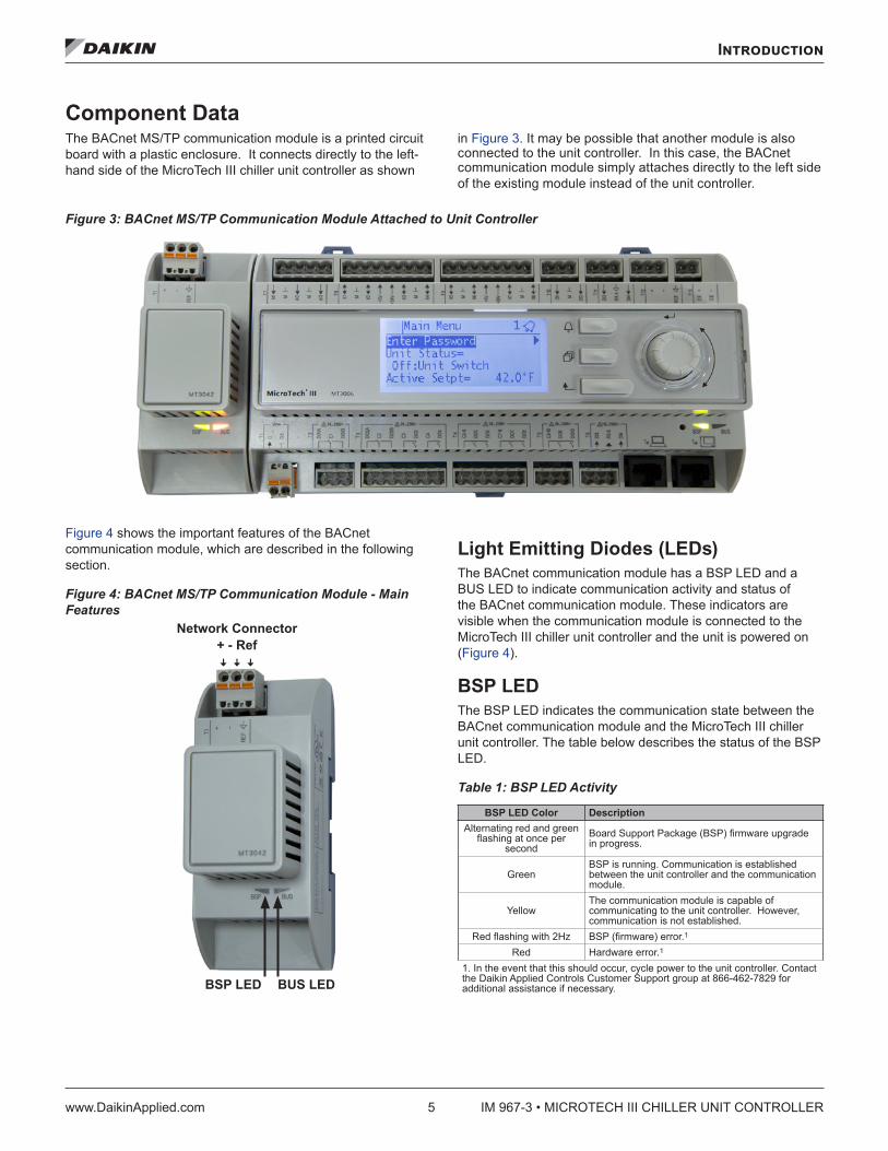
Component DataThe BACnet MS/TP communication module is a printed circuit board with a plastic enclosure. It connects directly to the left-hand side of the MicroTech III chiller unit controller as shown
in Figure 3. It may be possible that another module is also connected to the unit controller. In this case, the BACnet communication module simply attaches directly to the left side of the existing module instead of the unit controller.
Figure 3: BACnet MS/TP Communication Module Attached to Unit Controller
Figure 4 shows the important features of the BACnet communication module, which are described in the following section.
Figure 4: BACnet MS/TP Communication Module - Main Features
Light Emitting Diodes (LEDs)The BACnet communication module has a BSP LED and a BUS LED to indicate communication activity and status of the BACnet communication module. These indicators are visible when the communication module is connected to the MicroTech III chiller unit controller and the unit is powered on (Figure 4).
BSP LEDThe BSP LED indicates the communication state between the BACnet communication module and the MicroTech III chiller unit controller. The table below describes the status of the BSP LED.
Table 1: BSP LED Activity
BSP LED Color DescriptionAlternating red and green
flashing at once per second
Board Support Package (BSP) firmware upgrade in progress.
GreenBSP is running. Communication is established between the unit controller and the communication module.
YellowThe communication module is capable of communicating to the unit controller. However, communication is not established.
Red flashing with 2Hz BSP (firmware) error.1
Red Hardware error.1
1. In the event that this should occur, cycle power to the unit controller. Contact the Daikin Applied Controls Customer Support group at 866-462-7829 for additional assistance if necessary.BUS LEDBSP LED
Network Connector+ - Ref
ꜜ ꜜ ꜜ
IM 967-3 • MICROTECH III CHILLER UNIT CONTROLLER 6 www.DaikinApplied.com
Introduction
BUS LEDsThe BUS LED indicates the communication status between the BACnet communication module and the BACnet MS/TP network. The table below describes the status of the BUS LED.
Table 2: BUS LED Activity
BUS LED Color Description
Green The unit controller is capable of communicating to the network.
Yellow Communication module is initializing.
Red1 Communication error. The unit controller is not capable of communicating to the network.
1. For BACnet communication modules with BSP 10.xx or newer, the status indicates “Other” when there is a network communication error.
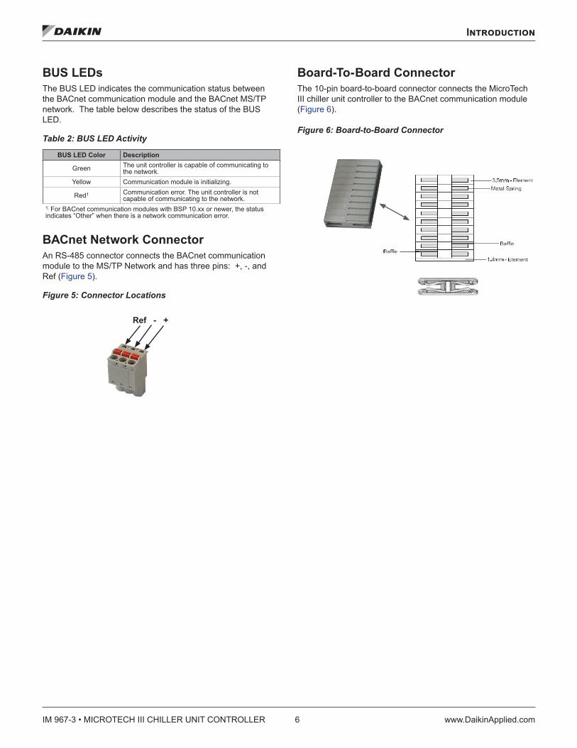
BACnet Network ConnectorAn RS-485 connector connects the BACnet communication module to the MS/TP Network and has three pins: +, -, and Ref (Figure 5).
Figure 5: Connector Locations
Board-To-Board ConnectorThe 10-pin board-to-board connector connects the MicroTech III chiller unit controller to the BACnet communication module (Figure 6).
Figure 6: Board-to-Board Connector
Ref - +
Installation
www.DaikinApplied.com 7 IM 967-3 • MICROTECH III CHILLER UNIT CONTROLLER
Installation
Installation and MountingThe following section describes how to field install a new BACnet MS/TP communication module or replace an existing module on the MicroTech III chiller unit controller.
CAUTIONElectrostatic discharge hazard. Can cause equipment damage.This equipment contains sensitive electronic components that may be damaged by electrostatic discharge from your hands. Before you handle a communication module, you need to touch a grounded object, such as the metal enclosure, in order to discharge the electrostatic potential from your body.
WARNINGElectric shock hazard . Can cause personal injury or equipment damage.
This equipment must be properly grounded. Only personnel knowledgeable in the operation of the equipment being controlled must perform connections and service to the unit controller.
Field Installation Kit The BACnet communication module field-installed kit ships with the following items:
• The BACnet MS/TP communication module • Network connector (attached to module) - Figure 5 • Board-to-board connector - Figure 6• This manual (IM 967)
Installing a new Communication ModuleFollow these steps to install a BACnet communication module on the unit controller. The BACnet communication module can be connected directly to the unit controller itself or to an existing module, if one is attached.
NOTE: There is a limit of three devices that can be attached to the left side of the unit controller.
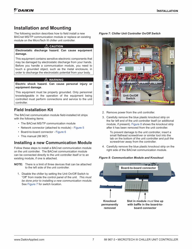
1. Disable the chiller by setting the Unit On/Off Switch to “Off” from inside the control panel of the unit. This must be done prior to installing a new communication module. See Figure 7 for switch location.
Figure 7: Chiller Unit Controller On/Off Switch
2. Remove power from the unit controller.
3. Carefully remove the blue plastic knockout strip on the far left end of the unit controller itself (or additional module, if present). Figure 8 shows the knockout strip after it has been removed from the unit controller.
To prevent damage to the unit controller, insert a small flathead screwdriver or similar tool into the tab on the bottom of the unit controller and pull the screwdriver away from the controller.
4. Carefully remove the blue plastic knockout strip on the right side of the BACnet communication module.
Figure 8: Communication Module and Knockout
Unit On/Off Switch
Knockout permanently
removed
Slot in module must line up with baffle in the board-to-
board connector
Board-to-board connector
IM 967-3 • MICROTECH III CHILLER UNIT CONTROLLER 8 www.DaikinApplied.com
Installation
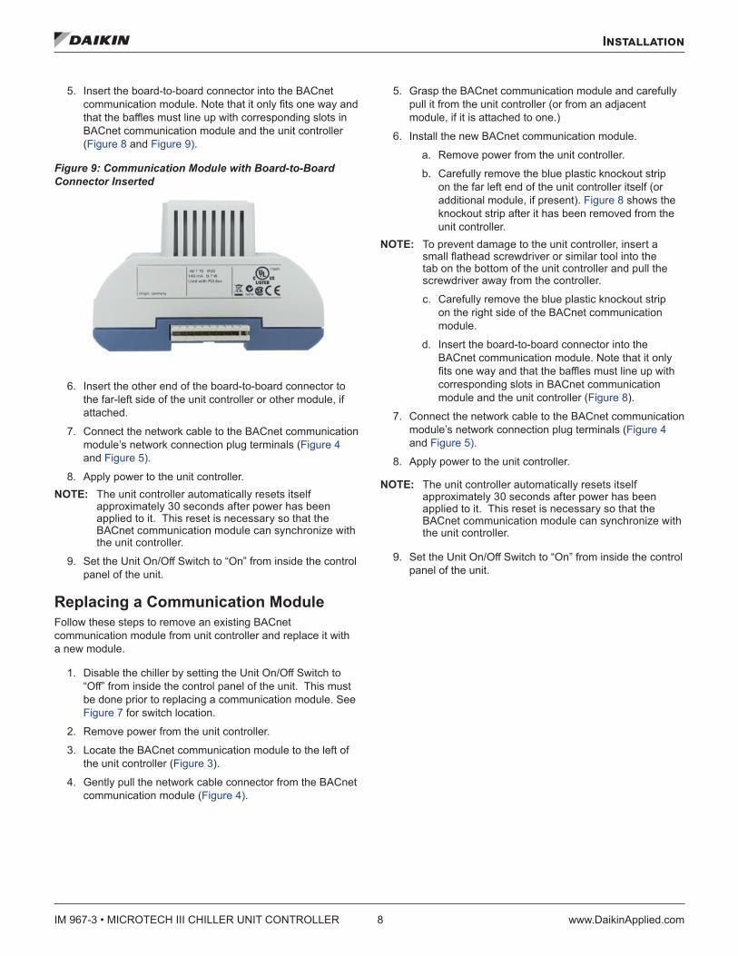
5. Insert the board-to-board connector into the BACnet communication module. Note that it only fits one way and that the baffles must line up with corresponding slots in BACnet communication module and the unit controller (Figure 8 and Figure 9).
Figure 9: Communication Module with Board-to-Board Connector Inserted
6. Insert the other end of the board-to-board connector to the far-left side of the unit controller or other module, if attached.
7. Connect the network cable to the BACnet communication module’s network connection plug terminals (Figure 4 and Figure 5).
8. Apply power to the unit controller.NOTE: The unit controller automatically resets itself
approximately 30 seconds after power has been applied to it. This reset is necessary so that the BACnet communication module can synchronize with the unit controller.
9. Set the Unit On/Off Switch to “On” from inside the control panel of the unit.
Replacing a Communication ModuleFollow these steps to remove an existing BACnet communication module from unit controller and replace it with a new module.
1. Disable the chiller by setting the Unit On/Off Switch to “Off” from inside the control panel of the unit. This must be done prior to replacing a communication module. See Figure 7 for switch location.
2. Remove power from the unit controller.
3. Locate the BACnet communication module to the left of the unit controller (Figure 3).
4. Gently pull the network cable connector from the BACnet communication module (Figure 4).
5. Grasp the BACnet communication module and carefully pull it from the unit controller (or from an adjacent module, if it is attached to one.)
6. Install the new BACnet communication module.
a. Remove power from the unit controller.
b. Carefully remove the blue plastic knockout strip on the far left end of the unit controller itself (or additional module, if present). Figure 8 shows the knockout strip after it has been removed from the unit controller.
NOTE: To prevent damage to the unit controller, insert a small flathead screwdriver or similar tool into the tab on the bottom of the unit controller and pull the screwdriver away from the controller.
c. Carefully remove the blue plastic knockout strip on the right side of the BACnet communication module.
d. Insert the board-to-board connector into the BACnet communication module. Note that it only fits one way and that the baffles must line up with corresponding slots in BACnet communication module and the unit controller (Figure 8).
7. Connect the network cable to the BACnet communication module’s network connection plug terminals (Figure 4 and Figure 5).
8. Apply power to the unit controller.
NOTE: The unit controller automatically resets itself approximately 30 seconds after power has been applied to it. This reset is necessary so that the BACnet communication module can synchronize with the unit controller.
9. Set the Unit On/Off Switch to “On” from inside the control panel of the unit.
Network Configuration
www.DaikinApplied.com 9 IM 967-3 • MICROTECH III CHILLER UNIT CONTROLLER
Network Configuration
The following section describes how to configure the BACnet MS/TP communication module for BAS network integration. Follow these instructions to set addressing parameters for the BACnet communication module using the keypad/display on MicroTech III chiller unit controller.
Table 3 describes the available BACnet MS/TP network parameters used to establish communication between the unit controller and the BAS. Default values and acceptable ranges are shown along with detailed descriptions.
BACnet MS/TP Configuration Below is a preview of the configuration procedure, followed by detailed instructions for each step.
1. Disable the chiller.
2. Enter the password.
3. Set Device Instance Number, MS/TP MAC Address, Transmission (Baud) Rate, and Max Masters - typically done during initial configuration.
4. Set other network parameters as required.
5. Once all parameters have been adjusted, select Apply Changes to save new settings and cycle power to the unit controller.
NOTE: It is recommended that you modify all parameters before selecting Apply Changes. This minimizes the number of power cycles to the unit controller.
6. Enable the chiller.
Disable the Chiller1. Set the Unit On/Off Switch to “Off” from inside the control
panel of the unit. See Figure 7 for switch location.
Enter Password1. If you have not already entered a password and are
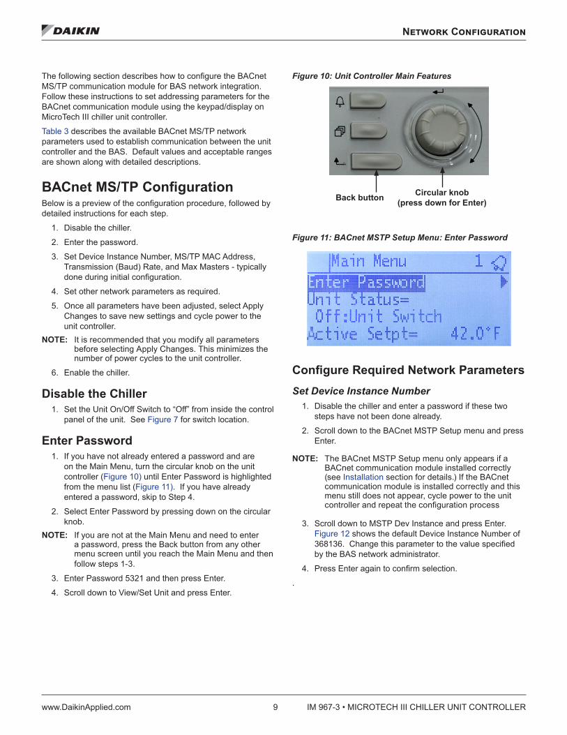
on the Main Menu, turn the circular knob on the unit controller (Figure 10) until Enter Password is highlighted from the menu list (Figure 11). If you have already entered a password, skip to Step 4.
2. Select Enter Password by pressing down on the circular knob.
NOTE: If you are not at the Main Menu and need to enter a password, press the Back button from any other menu screen until you reach the Main Menu and then follow steps 1-3.
3. Enter Password 5321 and then press Enter.
4. Scroll down to View/Set Unit and press Enter.
Figure 10: Unit Controller Main Features
Figure 11: BACnet MSTP Setup Menu: Enter Password
Configure Required Network ParametersSet Device Instance Number
1. Disable the chiller and enter a password if these two steps have not been done already.
2. Scroll down to the BACnet MSTP Setup menu and press Enter.
NOTE: The BACnet MSTP Setup menu only appears if a BACnet communication module installed correctly (see Installation section for details.) If the BACnet communication module is installed correctly and this menu still does not appear, cycle power to the unit controller and repeat the configuration process
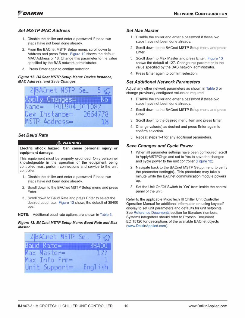
3. Scroll down to MSTP Dev Instance and press Enter. Figure 12 shows the default Device Instance Number of 368136. Change this parameter to the value specified by the BAS network administrator.
4. Press Enter again to confirm selection.
.
Circular knob (press down for Enter)Back button
IM 967-3 • MICROTECH III CHILLER UNIT CONTROLLER 10 www.DaikinApplied.com
Network Configuration
Set MS/TP MAC Address
1. Disable the chiller and enter a password if these two steps have not been done already.
2. From the BACnet MSTP Setup menu, scroll down to Address and press Enter. Figure 12 shows the default MAC Address of 18. Change this parameter to the value specified by the BAS network administrator.
3. Press Enter again to confirm selection.
Figure 12: BACnet MSTP Setup Menu: Device Instance, MAC Address, and Save Changes
Set Baud Rate WARNING
Electric shock hazard . Can cause personal injury or equipment damage.This equipment must be properly grounded. Only personnel knowledgeable in the operation of the equipment being controlled must perform connections and service to the unit controller.
1. Disable the chiller and enter a password if these two steps have not been done already.
2. Scroll down to the BACnet MSTP Setup menu and press Enter.
3. Scroll down to Baud Rate and press Enter to select the desired baud rate. Figure 13 shows the default of 38400 bps.
NOTE: Additional baud rate options are shown in Table 3.
Figure 13: BACnet MSTP Setup Menu: Baud Rate and Max Master
Set Max Master1. Disable the chiller and enter a password if these two
steps have not been done already.
2. Scroll down to the BACnet MSTP Setup menu and press Enter.
3. Scroll down to Max Master and press Enter. Figure 13 shows the default of 127. Change this parameter to the value specified by the BAS network administrator.
4. Press Enter again to confirm selection.
Set Additional Network Parameters Adjust any other network parameters as shown in Table 3 or change previously configured values as required.
1. Disable the chiller and enter a password if these two steps have not been done already.
2. Scroll down to the BACnet MSTP Setup menu and press Enter.
3. Scroll down to the desired menu item and press Enter.
4. Change value(s) as desired and press Enter again to confirm selection.
5. Repeat steps 1-4 for any additional parameters.
Save Changes and Cycle Power1. When all parameter settings have been configured, scroll
to ApplyMSTPChgs and set to Yes to save the changes and cycle power to the unit controller (Figure 12).
2. Navigate back to the BACnet MSTP Setup menu to verify the parameter setting(s). This procedure may take a minute while the BACnet communication module powers up.
3. Set the Unit On/Off Switch to “On” from inside the control panel of the unit.
Refer to the applicable MicroTech III Chiller Unit Controller Operation Manual for additional information on using keypad/display to set unit parameters and defaults for unit setpoints. See Reference Documents section for literature numbers. Systems integrators should refer to Protocol Document ED 15120 for descriptions of the available BACnet objects (www.DaikinApplied.com).
Network Configuration
www.DaikinApplied.com 11 IM 967-3 • MICROTECH III CHILLER UNIT CONTROLLER
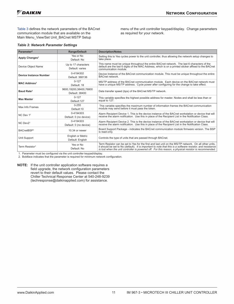
Table 3 defines the network parameters of the BACnet communication module that are available on the Main Menu_View/Set Unit_BACnet MSTP Setup
menu of the unit controller keypad/display. Change parameters as required for your network.
Table 3: Network Parameter Settings
Parameter2 Range/Default Description/Notes
Apply Changes1 Yes or No Default: No
Setting this to Yes cycles power to the unit controller, thus allowing the network setup changes to take place.
Device Object NameUp to 17 characters
Default: variesThis name must be unique throughout the entire BACnet network. The last 6 characters of the default are the last 6 digits of the MAC Address, which is on a printed sticker affixed to the BACnet communication module.
Device Instance Number 0-4194302 Default: 368136
Device Instance of the BACnet communication module. This must be unique throughout the entire BACnet network.
MAC Address1 0-127 Default: 18
MS/TP address of the BACnet communication module. Each device on the BACnet network must have a unique MS/TP address. Cycle power after configuring for the change to take effect.
Baud Rate1 9600,19200,38400,76800Default: 38400
Data transfer speed (bps) of the BACnet MS/TP network.
Max Master 0-127 Default:127
This variable specifies the highest possible address for master. Nodes and shall be less than or equal to 127.
Max Info Frames0-255
Default:10 This variable specifies the maximum number of information frames the BACnet communication module may send before it must pass the token.
NC Dev 11 0-4194303 Default: 0 (no device)
Alarm Recipient Device 1. This is the device instance of the BACnet workstation or device that will receive the alarm notification. Use this in place of the Recipient List in the Notification Class.
NC Dev21 0-4194303 Default: 0 (no device)
Alarm Recipient Device 2. This is the device instance of the BACnet workstation or device that will receive the alarm notification. Use this in place of the Recipient List in the Notification Class.
BACnetBSP1 10.34 or newer Board Support Package - indicates the BACnet communication module firmware version. The BSP is read-only.
Unit SupportEnglish or Metric Default: English
Controls the type of units that are passed through BACnet.
Term Resistor1 Yes or No Default: No
Term Resistor can be set to Yes for the first and last unit on the MS/TP network. On all other units, it should be set to No (default). It is important to note that this is a software resistor, and resistance is lost when the unit controller is powered off. For this reason, a physical resistor is recommended.
1. Parameter must be configured via the unit controller keypad/display.2. Boldface indicates that the parameter is required for minimum network configuration.
NOTE: If the unit controller application software requires a field upgrade, the network configuration parameters revert to their default values. Please contact the Chiller Technical Response Center at 540-248-9239 ([email protected]) for assistance.
IM 967-3 • MICROTECH III CHILLER UNIT CONTROLLER 12 www.DaikinApplied.com
Parts and Service
Parts and Service
TroubleshootingFollow these procedures if you can control the MicroTech III chiller unit controller from the keypad/display, but are not able to communicate with the unit via the network.
Network Parameters→ Verify that network parameters are set correctly as shown in Table 3
→ Make sure there are no duplicate devices on the network
Network wiringIf performance is unsatisfactory or network is experiencing issues such as noise, loss of data packets, or collisions:
→ Confirm that the shield is landed at only one point in the trunk
→ Be aware that network topology must be daisy-chain or line topology (no T-Taps or ring layout)
→ Verify that network wiring does not exceed 4000 ft total distance limit (without repeaters) at 76800 bps baud
→ Verify that polarity is maintained
→ Check that there are end-of-line termination resistors at the first and last device on the trunk. This is required by the EIA-485 specification
→ Verify that the network trunk avoids strong sources of electromagnetic interference (EMI)
→ Verify that the network trunk is not located near a DC load switch (relay)
Communications→ Verify that other devices on the network are still communicating
→ Verify that all appropriate configuration has been done to BAS server
Contact the Daikin Applied Controls Customer Support group at 866-462-7829 for additional assistance, if necessary.
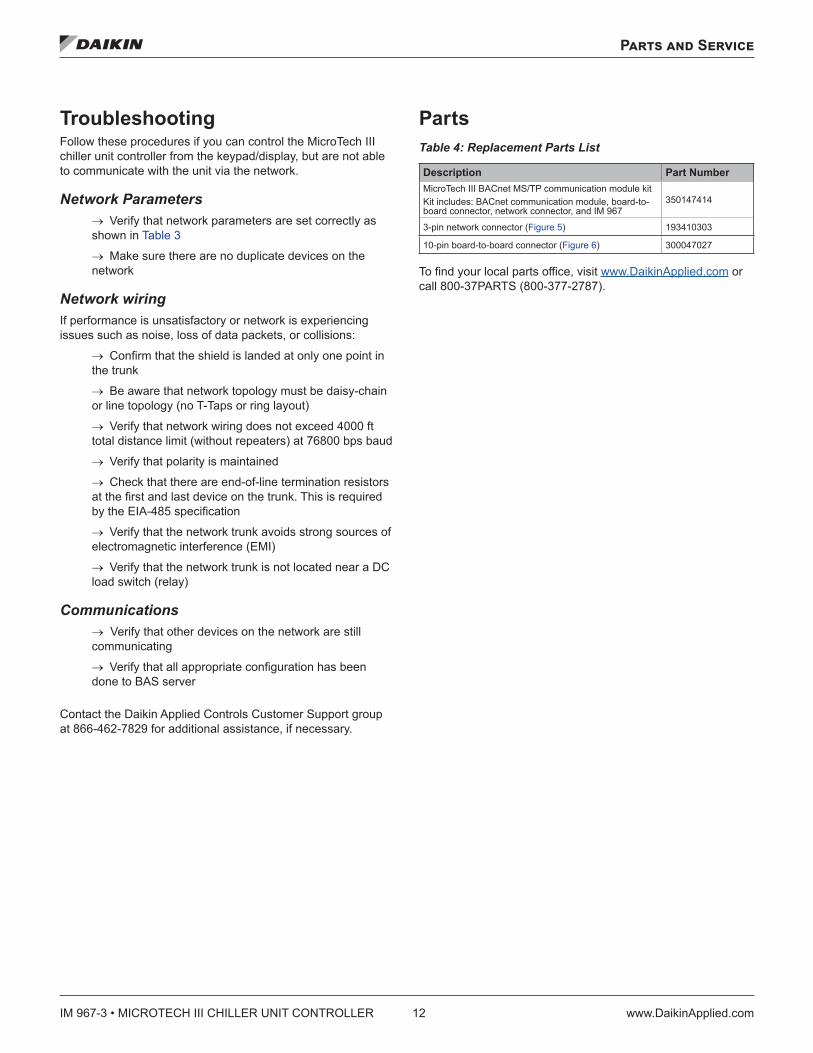
PartsTable 4: Replacement Parts List
Description Part Number
MicroTech III BACnet MS/TP communication module kitKit includes: BACnet communication module, board-to-board connector, network connector, and IM 967
350147414
3-pin network connector (Figure 5) 193410303
10-pin board-to-board connector (Figure 6) 300047027
To find your local parts office, visit www.DaikinApplied.com or call 800-37PARTS (800-377-2787).


IM 967-3 (3/17) ©2017 Daikin Applied | (800) 432–1342 | www.DaikinApplied.com
Daikin Applied Training and DevelopmentNow that you have made an investment in modern, efficient Daikin equipment, its care should be a high priority. For training information on all Daikin HVAC products, please visit us at www.DaikinApplied.com and click on Training, or call 540-248-9646 and ask for the Training Department.
Warranty
All Daikin equipment is sold pursuant to its standard terms and conditions of sale, including Limited Product Warranty. Consult your local Daikin Applied representative for warranty details. To find your local Daikin Applied representative, go to www.DaikinApplied.com.
Aftermarket Services
To find your local parts office, visit www.DaikinApplied.com or call 800-37PARTS (800-377-2787). To find your local service office, visit www.DaikinApplied.com or call 800-432-1342.
This document contains the most current product information as of this printing. For the most up-to-date product information, please go to www.DaikinApplied.com.
Products manufactured in an ISO Certified Facility.