Embed Size (px)
Citation preview
Engineering Data ED15063-5
Group: Controls
Part Number: ED 15063
Date: June 2013
Supersedes: ED15063-4
© 2013 Daikin McQuay
MicroTech® II Chiller Unit Controller Protocol Information Modbus® Protocol
WSC Water-Cooled Centrifugal, Single-Compressor
WDC Water-Cooled Centrifugal, Dual-Compressor
WPV Water-Cooled Centrifugal, Single-Compressor
HSC Water-Cooled Single-Compressor Centrifugal, Heat Recovery
HDC Water-Cooled Dual-Compressor Centrifugal, Heat Recovery
TSC Water-Cooled Single-Compressor Centrifugal, Templifier
WMC Water-Cooled Centrifugal, Magnetic Bearing
WCC Water-Cooled Centrifugal, Counterflow
AGZ Air-Cooled Global Scroll
ACZ Air-Cooled Scroll Condensing Unit
WGZ Water-Cooled Global Scroll
AGS Air-Cooled Global Screw
WGS Water-Cooled Global Screw
TGZ Templifier™ Water Heater
2 ED 15063-5
Table of Contents
TABLE OF CONTENTS ........................................................................................................................................................ 2
LIMITED WARRANTY .............................................................................................................................................................. 4 NOTICE .................................................................................................................................................................................. 4 REVISION HISTORY ............................................................................................................................................................... 4 SOFTWARE REVISION ........................................................................................................................................................... 4 REFERENCE DOCUMENTS .................................................................................................................................................... 4
INTRODUCTION .................................................................................................................................................................... 6
CHILLER MODELS ................................................................................................................................................................. 6 CONTROLLER DATA POINTS ................................................................................................................................................. 6
MODBUS PROTOCOL INFORMATION ............................................................................................................................ 7
COMPATIBILITY ...................................................................................................................................................................... 7 PROTOCOL DEFINITIONS ...................................................................................................................................................... 7 VALID FUNCTION CODES ...................................................................................................................................................... 7 VALID ERROR CODES ........................................................................................................................................................... 8 MODBUS DATA POINT ........................................................................................................................................................... 8 EXAMPLE DATA POINT: CHILLER ENABLE ............................................................................................................................ 8 CONFIGURING THE UNIT CONTROLLER ................................................................................................................................ 8 SET UP THE UNIT FOR NETWORK CONTROL ........................................................................................................................ 8
TYPICAL APPLICATION: MINIMUM INTEGRATION ..................................................................................................... 9
DISPLAY IMPORTANT DATA POINTS ..................................................................................................................................... 9
COMPREHENSIVE DATA POINT TABLES ................................................................................................................... 10
MODBUS DATA POINTS ....................................................................................................................................................... 10
DETAILED DATA POINT INFORMATION ...................................................................................................................... 13
ACTIVE SETPOINT ............................................................................................................................................................... 14 ACTUAL CAPACITY .............................................................................................................................................................. 14 ACTUAL RPM ...................................................................................................................................................................... 14 CAPACITY LIMIT OUTPUT .................................................................................................................................................... 14 CAPACITY LIMIT SETPOINT ................................................................................................................................................. 14 CAVITY TEMPERATURE ....................................................................................................................................................... 15 COMPRESSOR DISCHARGE TEMPERATURE ....................................................................................................................... 15 CHILLER ENABLE ................................................................................................................................................................ 15 CHILLER LIMITED ................................................................................................................................................................. 15 CHILLER LOCAL/REMOTE ................................................................................................................................................... 15 CHILLER MODE OUTPUT ..................................................................................................................................................... 15 CHILLER MODE SETPOINT .................................................................................................................................................. 16 COMPRESSOR 2 ACTIVE CAPACITY LIMIT ............................................................................................................................ 16 CHILLER STATUS ................................................................................................................................................................ 16 CHILLER POWER .................................................................................................................................................................. 16 COMPRESSOR CURRENT .................................................................................................................................................... 16 COMPRESSOR DISCHARGE TEMPERATURE ....................................................................................................................... 17 COMPRESSOR PERCENT RLA ............................................................................................................................................ 17 COMPRESSOR POWER ....................................................................................................................................................... 18 COMPRESSOR RUN HOURS ................................................................................................................................................ 18 COMPRESSOR SELECT .......................................................................................................................................................... 19 COMPRESSOR STARTS ....................................................................................................................................................... 19 COMPRESSOR SUCTION LINE TEMPERATURE ................................................................................................................... 20 COMPRESSOR VOLTAGE .................................................................................................................................................... 20 CONDENSER ENTERING WATER TEMPERATURE ............................................................................................................... 21 CONDENSER FLOW SWITCH STATUS ................................................................................................................................. 21
3 ED 15063-5
CONDENSER LEAVING WATER TEMPERATURE .................................................................................................................. 21 CONDENSER PUMP RUN HOURS ........................................................................................................................................ 21 CONDENSER REFRIGERANT PRESSURE ............................................................................................................................. 21 CONDENSER SATURATED REFRIGERANT TEMPERATURE .................................................................................................. 21 CONDENSER WATER FLOW RATE ...................................................................................................................................... 22 CONDENSER WATER PUMP STATUS ..................................................................................................................................... 22 COOL SETPOINT .................................................................................................................................................................. 22 DESIGN RPM ...................................................................................................................................................................... 22 EVAPORATOR ENTERING WATER TEMPERATURE .............................................................................................................. 22 EVAPORATOR FLOW SWITCH STATUS ................................................................................................................................ 22 EVAPORATOR LEAVING WATER TEMPERATURE FOR UNIT ................................................................................................ 22 EVAPORATOR LEAVING WATER TEMPERATURE FOR COMPRESSOR ................................................................................. 23 EVAPORATOR PUMP RUN HOURS ...................................................................................................................................... 23 EVAPORATOR REFRIGERANT PRESSURE ........................................................................................................................... 23 EVAPORATOR SATURATED REFRIGERANT TEMPERATURE ................................................................................................ 23 EVAPORATOR WATER FLOW RATE ..................................................................................................................................... 24 EVAPORATOR WATER PUMP STATUS ................................................................................................................................. 24 HEAT RECOVERY ENTERING WATER TEMPERATURE ........................................................................................................ 24 HEAT RECOVERY LEAVING WATER TEMPERATURE ........................................................................................................... 24 HEAT SETPOINT .................................................................................................................................................................. 24 ICE SETPOINT ...................................................................................................................................................................... 24 IGV PERCENTAGE OPEN .................................................................................................................................................... 24 INVERTER TEMPERATURE ................................................................................................................................................... 25 LIQUID LINE REFRIGERANT PRESSURE .............................................................................................................................. 25 LIQUID LINE REFRIGERANT TEMPERATURE ........................................................................................................................ 25 MAXIMUM RPM ................................................................................................................................................................... 25 MINIMUM RPM .................................................................................................................................................................... 25 OIL FEED PRESSURE .......................................................................................................................................................... 26 OIL FEED TEMPERATURE .................................................................................................................................................... 26 OIL SUMP PRESSURE .......................................................................................................................................................... 26 OIL SUMP TEMPERATURE ................................................................................................................................................... 26 OUTDOOR AIR TEMPERATURE ............................................................................................................................................ 27 PUMP SELECT ..................................................................................................................................................................... 27 RUN ENABLED ..................................................................................................................................................................... 27
ALARMS ................................................................................................................................................................................ 28
ALARM CLASSES ................................................................................................................................................................. 28 FAULT ALARMS .................................................................................................................................................................... 28 PROBLEM ALARMS .............................................................................................................................................................. 28 WARNING ALARMS .............................................................................................................................................................. 28 ALARM HANDLING ............................................................................................................................................................... 28 ALARM DIGITAL OUTPUT ..................................................................................................................................................... 28 CLEAR ALARMS ................................................................................................................................................................... 28 ACTIVE ALARMS .................................................................................................................................................................. 29
INDEX OF DETAILED POINT INFORMATION ............................................................................................................... 34
4 ED 15063-5
Limited Warranty Consult your local Daikin McQuay Representative for warranty details. Refer to Form 933-43285Y. To find your local Daikin McQuay Representative, go to www.daikinmcquay.com.
Notice © 2013 Daikin McQuay, Minneapolis MN. All rights reserved throughout the world. Daikin McQuay reserves the right to change any information contained herein without prior notice. The user is responsible for determining whether this product is appropriate for his or her application.
™ ® The following are trademarks or registered trademarks of their respective companies. Modbus is a registered trademark of Gould, Inc. Windows is a registered trademark of Microsoft Corporation. MicroTech II is a registered trademark of Daikin McQuay.
Revision History ED 15063-0 May 15, 2003 Preliminary release. ED 15063-1 May 18, 2005 Added points for Solid State Starter – Current, Voltage, Power and Power Factor
Corrected some incorrect register listings Changed doc to have only Holding Registers and Coils Added WGS and WMC data Added WMC, HSC HDC, and TSC to front page and Chiller Model table
ED 15063-2 Nov 22, 2005 Added WCC to front page and Chiller Model table Corrected Modbus Alarms table
Added Compressor Current, Compressor Power and Compressor Voltage to the Compressor Select Table
ED 15063-3 April 14, 2009 Added TGZmodel to all applicable tables. Removed reference to OITS panel and added reference to unit keypad details in the “Set up unit for network control” section. Added Index column to Comphrenesive Data Point table; corrected Chiller Status holding register in table and also in detailed data section. Removed reference to Chiller On/Off--use Run Enabled instead.
ED 15063-5 Jan 21, 2013 Added individual compressor data points.
Software Revision This edition documents all versions of the standard MicroTech II® Chiller Unit Controller firmware and all subsequent revisions until otherwise indicated.
Reference Documents Company Number Title Source
McQuay International IOMM WSC WDC The McQuay DISTINCTION Series Single/Dual Compressor Centrifugal Chillers Installation, Operating and Maintenance Manual
www.mcquay.com
McQuay International OM CentrifMicro II MicroTech II Controller for Centrifugal Chillers and Templifiers Operating Manual
www.mcquay.com
McQuay International IM 743 MicroTech II Chiller Unit Controller Modbus Communication Module Installation Manual
www.mcquay.com
McQuay International IMM AGS IMM AGSB GeneSys Air-Cooled Screw Compressor Chiller www.mcquay.com
McQuay International IOMM ACZ/AGZ Air-Cooled Scroll Condensing Unit & Air-Cooled Scroll Chiller w/Remote Evaporators Installation, Operation, and Maintenance Manual
www.mcquay.com
McQuay International IOMM ACZ Air-Cooled Scroll Condensing Unit Installation, Operation, and Maintenance Manual
www.mcquay.com
McQuay International
IOMM AGZ IOMM AGZ1
Air-Cooled Scroll Compressor Chiller & Air-Cooled Scroll Compressor Water Chiller Installation, Operation, and Maintenance Manual
www.mcquay.com
McQuay International IOMM WGZ Water-Cooled Scroll Compressor Chiller Installation, Operation and Maintenance Manual
www.mcquay.com
McQuay International IOMM WPV WPV Centrifugal Compressor Chillers Installation, Operating and Maintenance Manual
www.mcquay.com
5 ED 15063-5
McQuay International OM AGS GeneSys Air-Cooled Screw Compressor Chiller Operation Manual www.mcquay.com
McQuay International IOMM TSC MicroTech II Templifier Single Compressor Centrifugal Installation, Operation, and Maintenance Manual
www.mcquay.com
McQuay International OMM TGZ MicroTech II Templifier TGZ Heat Recovery Water Heaters Operating Manual
www.mcquay.com
Modbus-IDA.ORG MODBUS Application Protocol Specification V1.1b www.Modbus.org
Modbus-IDA.ORG MODBUS over Serial Line Specification and Implementation Guide V1.02 www.Modbus.org
6 ED 15063-5
Introduction This document contains the necessary information to incorporate a MicroTech II Chiller Unit Controller from Daikin McQuay into your Building Automation System (BAS). It includes all necessary Modbus variables and corresponding MicroTech II Chiller Unit Controller data points. Modbus terms and principles are not defined. Refer to the appropriate specifications for definitions and details.
Chiller Models The following table lists the model designators of Daikin McQuay Chiller units and the corresponding description. WSC Water-Cooled Centrifugal, Single-Compressor WDC Water-Cooled Centrifugal, Dual-Compressor WPV Water-Cooled Centrifugal, Single-Compressor HSC Water-Cooled Single-Compressor Centrifugal, Heat Recovery HDC Water-Cooled Dual-Compressor Centrifugal, Heat Recovery TSC Water-Cooled Single-Compressor Centrifugal, Templifier WMC Water-Cooled Centrifugal, Magnetic Bearing WCC Water-Cooled Centrifugal, Counterflow AGZ Air-Cooled Global Scroll ACZ Air-Cooled Scroll Condensing Unit WGZ Water-Cooled Global Scroll AGS Air-Cooled Global Screw WGS Water-Cooled Global Screw TGZ Templifier™ Water Heater
Controller Data Points The MicroTech II Chiller Unit Controller contains data points or unit variables that are accessible from three different user interfaces: the unit keypad/display, the Operator Interface Touch Screen, or a Modbus serial network. Not all points are accessible from each interface. This manual lists all important data points and the corresponding network path for each applicable interface. Refer to the applicable Operation Manual for keypad/display and Operator Interface Touch Screen details. See Reference Documents on page 4 for manual part numbers.
7 ED 15063-5
Modbus Protocol Information
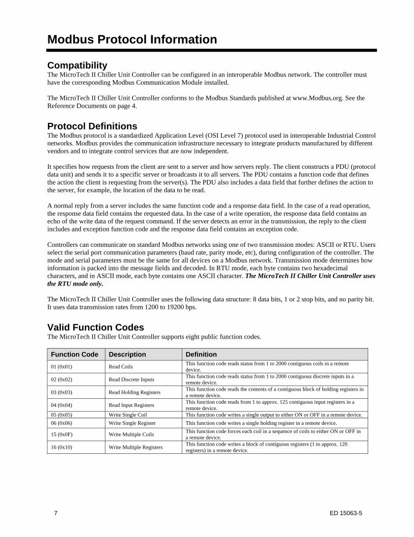
Compatibility The MicroTech II Chiller Unit Controller can be configured in an interoperable Modbus network. The controller must have the corresponding Modbus Communication Module installed. The MicroTech II Chiller Unit Controller conforms to the Modbus Standards published at www.Modbus.org. See the Reference Documents on page 4.
Protocol Definitions The Modbus protocol is a standardized Application Level (OSI Level 7) protocol used in interoperable Industrial Control networks. Modbus provides the communication infrastructure necessary to integrate products manufactured by different vendors and to integrate control services that are now independent. It specifies how requests from the client are sent to a server and how servers reply. The client constructs a PDU (protocol data unit) and sends it to a specific server or broadcasts it to all servers. The PDU contains a function code that defines the action the client is requesting from the server(s). The PDU also includes a data field that further defines the action to the server, for example, the location of the data to be read. A normal reply from a server includes the same function code and a response data field. In the case of a read operation, the response data field contains the requested data. In the case of a write operation, the response data field contains an echo of the write data of the request command. If the server detects an error in the transmission, the reply to the client includes and exception function code and the response data field contains an exception code. Controllers can communicate on standard Modbus networks using one of two transmission modes: ASCII or RTU. Users select the serial port communication parameters (baud rate, parity mode, etc), during configuration of the controller. The mode and serial parameters must be the same for all devices on a Modbus network. Transmission mode determines how information is packed into the message fields and decoded. In RTU mode, each byte contains two hexadecimal characters, and in ASCII mode, each byte contains one ASCII character. The MicroTech II Chiller Unit Controller uses the RTU mode only. The MicroTech II Chiller Unit Controller uses the following data structure: 8 data bits, 1 or 2 stop bits, and no parity bit. It uses data transmission rates from 1200 to 19200 bps.
Valid Function Codes The MicroTech II Chiller Unit Controller supports eight public function codes.
Function Code Description Definition
01 (0x01) Read Coils This function code reads status from 1 to 2000 contiguous coils in a remote device.
02 (0x02) Read Discrete Inputs This function code reads status from 1 to 2000 contiguous discrete inputs in a remote device.
03 (0x03) Read Holding Registers This function code reads the contents of a contiguous block of holding registers in a remote device.
04 (0x04) Read Input Registers This function code reads from 1 to approx. 125 contiguous input registers in a remote device.
05 (0x05) Write Single Coil This function code writes a single output to either ON or OFF in a remote device.
06 (0x06) Write Single Register This function code writes a single holding register in a remote device.
15 (0x0F) Write Multiple Coils This function code forces each coil in a sequence of coils to either ON or OFF in a remote device.
16 (0x10) Write Multiple Registers This function code writes a block of contiguous registers (1 to approx. 120 registers) in a remote device.
8 ED 15063-5
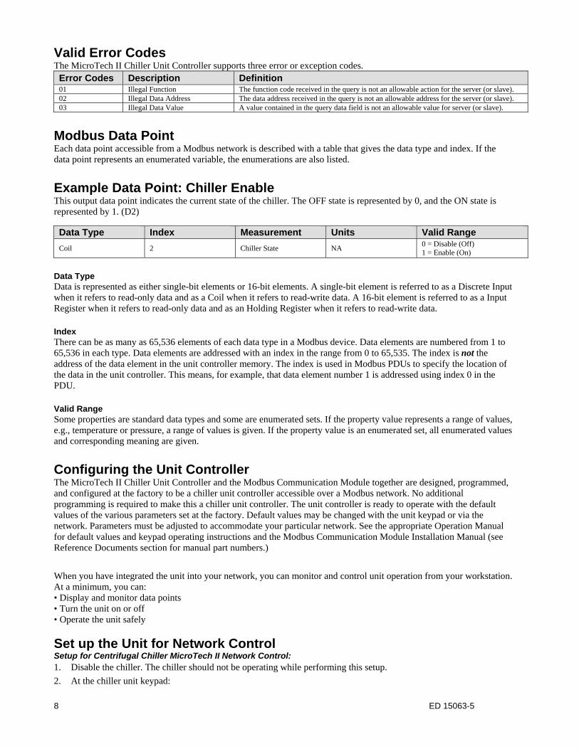
Valid Error Codes The MicroTech II Chiller Unit Controller supports three error or exception codes. Error Codes Description Definition 01 Illegal Function The function code received in the query is not an allowable action for the server (or slave).02 Illegal Data Address The data address received in the query is not an allowable address for the server (or slave).03 Illegal Data Value A value contained in the query data field is not an allowable value for server (or slave).
Modbus Data Point Each data point accessible from a Modbus network is described with a table that gives the data type and index. If the data point represents an enumerated variable, the enumerations are also listed.
Example Data Point: Chiller Enable This output data point indicates the current state of the chiller. The OFF state is represented by 0, and the ON state is represented by 1. (D2)
Data Type Index Measurement Units Valid Range
Coil 2 Chiller State NA 0 = Disable (Off) 1 = Enable (On)
Data Type Data is represented as either single-bit elements or 16-bit elements. A single-bit element is referred to as a Discrete Input when it refers to read-only data and as a Coil when it refers to read-write data. A 16-bit element is referred to as a Input Register when it refers to read-only data and as an Holding Register when it refers to read-write data. Index There can be as many as 65,536 elements of each data type in a Modbus device. Data elements are numbered from 1 to 65,536 in each type. Data elements are addressed with an index in the range from 0 to 65,535. The index is not the address of the data element in the unit controller memory. The index is used in Modbus PDUs to specify the location of the data in the unit controller. This means, for example, that data element number 1 is addressed using index 0 in the PDU. Valid Range Some properties are standard data types and some are enumerated sets. If the property value represents a range of values, e.g., temperature or pressure, a range of values is given. If the property value is an enumerated set, all enumerated values and corresponding meaning are given.
Configuring the Unit Controller The MicroTech II Chiller Unit Controller and the Modbus Communication Module together are designed, programmed, and configured at the factory to be a chiller unit controller accessible over a Modbus network. No additional programming is required to make this a chiller unit controller. The unit controller is ready to operate with the default values of the various parameters set at the factory. Default values may be changed with the unit keypad or via the network. Parameters must be adjusted to accommodate your particular network. See the appropriate Operation Manual for default values and keypad operating instructions and the Modbus Communication Module Installation Manual (see Reference Documents section for manual part numbers.)
When you have integrated the unit into your network, you can monitor and control unit operation from your workstation. At a minimum, you can: • Display and monitor data points • Turn the unit on or off • Operate the unit safely
Set up the Unit for Network Control Setup for Centrifugal Chiller MicroTech II Network Control: 1. Disable the chiller. The chiller should not be operating while performing this setup.
2. At the chiller unit keypad:
9 ED 15063-5
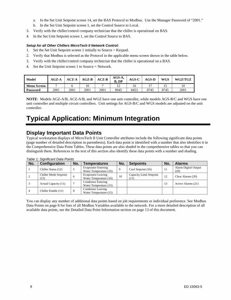
a. In the Set Unit Setpoint screen 14, set the BAS Protocol to Modbus. Use the Manager Password of “2001.” b. In the Set Unit Setpoint screen 1, set the Control Source to Local.
3. Verify with the chiller/control company technician that the chiller is operational on BAS.
4. In the Set Unit Setpoint screen 1, set the Control Source to BAS. Setup for all Other Chillers MicroTech II Network Control: 1. Set the Set Unit Setpoint screen 1 initially to Source = Keypad.
2. Verify that Modbus is selected as the Protocol in the applicable menu screen shown in the table below.
3. Verify with the chiller/control company technician that the chiller is operational on a BAS.
4. Set the Unit Setpoint screen 1 to Source = Network.
Model AGZ-A ACZ-A AGZ-B ACZ-B AGS-A, B, DP
AGS-C AGS-D WGS WGZ/TGZ
Menu Screen 7 6 10 7 12 16 17 15 10 Password 2001 2001 2001 2001 8945 8453 8745 8745 2001
NOTE: Models AGZ-A/B, ACZ-A/B, and WGZ have one unit controller, while models AGS-B/C and WGS have one unit controller and multiple circuit controllers. Unit settings for AGS-B/C and WGS models are adjusted on the unit controller.
Typical Application: Minimum Integration
Display Important Data Points Typical workstation displays of MicroTech II Unit Controller attributes include the following significant data points (page number of detailed description in parenthesis). Each data point is identified with a number that also identifies it in the Comprehensive Data Point Tables. These data points are also shaded in the comprehensive tables so that you can distinguish them. References in the text of this section also identify these data points with a number and shading. Table 1: Significant Data Points No. Configuration No. Temperatures No. Setpoints No. Alarms
1 Chiller Status (12) 5 Evaporator Entering Water Temperature (16)
9 Cool Setpoint (16) 11 Alarm Digital Output (20)
2 Chiller Mode Setpoint (12) 6
Evaporator Leaving Water Temperature (16)
10 Capacity Limit Setpoint (11)
12 Clear Alarms (20)
3 Actual Capacity (11) 7 Condenser Entering Water Temperature (15)
13 Active Alarms (21)
4 Chiller Enable (11) 8 Condenser Leaving Water Temperature (15)
You can display any number of additional data points based on job requirements or individual preference. See Modbus Data Points on page 8 for lists of all Modbus Variables available to the network. For a more detailed description of all available data points, see the Detailed Data Point Information section on page 13 of this document.
10 ED 15063-5
Comprehensive Data Point Tables
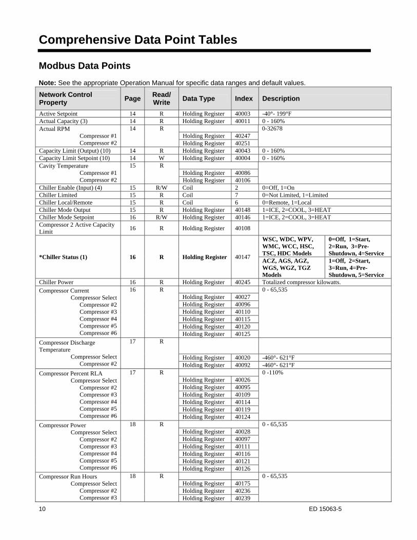
Modbus Data Points Note: See the appropriate Operation Manual for specific data ranges and default values.
Network Control Property
Page Read/ Write
Data Type Index Description
Active Setpoint 14 R Holding Register 40003 -40°- 199°F Actual Capacity (3) 14 R Holding Register 40011 0 - 160% Actual RPM
Compressor #1 Compressor #2
14 R 0-32678 Holding Register 40247 Holding Register 40251
Capacity Limit (Output) (10) 14 R Holding Register 40043 0 - 160% Capacity Limit Setpoint (10) 14 W Holding Register 40004 0 - 160% Cavity Temperature
Compressor #1 Compressor #2
15 R Holding Register 40086
Holding Register 40106 Chiller Enable (Input) (4) 15 R/W Coil 2 0=Off, 1=On Chiller Limited 15 R Coil 7 0=Not Limited, 1=Limited Chiller Local/Remote 15 R Coil 6 0=Remote, 1=Local Chiller Mode Output 15 R Holding Register 40148 1=ICE, 2=COOL, 3=HEAT Chiller Mode Setpoint 16 R/W Holding Register 40146 1=ICE, 2=COOL, 3=HEAT Compressor 2 Active Capacity Limit
16 R Holding Register 40108
*Chiller Status (1) 16 R Holding Register 40147
WSC, WDC, WPV, WMC, WCC, HSC, TSC, HDC Models
0=Off, 1=Start, 2=Run, 3=Pre-Shutdown, 4=Service
ACZ, AGS, AGZ, WGS, WGZ, TGZ Models
1=Off, 2=Start, 3=Run, 4=Pre-Shutdown, 5=Service
Chiller Power 16 R Holding Register 40245 Totalized compressor kilowatts. Compressor Current
Compressor Select Compressor #2 Compressor #3 Compressor #4 Compressor #5 Compressor #6
16 R 0 - 65,535 Holding Register 40027 Holding Register 40096 Holding Register 40110 Holding Register 40115 Holding Register 40120 Holding Register 40125
Compressor Discharge Temperature
Compressor Select Compressor #2
17 R
Holding Register 40020 -460°- 621°F Holding Register 40092 -460°- 621°F
Compressor Percent RLA Compressor Select
Compressor #2 Compressor #3 Compressor #4 Compressor #5 Compressor #6
17 R 0 -110% Holding Register 40026 Holding Register 40095 Holding Register 40109 Holding Register 40114 Holding Register 40119 Holding Register 40124
Compressor Power Compressor Select
Compressor #2 Compressor #3 Compressor #4 Compressor #5 Compressor #6
18 R 0 - 65,535 Holding Register 40028 Holding Register 40097 Holding Register 40111 Holding Register 40116 Holding Register 40121 Holding Register 40126
Compressor Run Hours Compressor Select
Compressor #2 Compressor #3
18 R 0 - 65,535 Holding Register 40175 Holding Register 40236 Holding Register 40239
11 ED 15063-5
Network Control Property
Page Read/ Write
Data Type Index Description
Compressor #4 Holding Register 40242 Compressor Select 18 R/W Holding Register 40161 See page 13 Compressor Starts
Compressor Select Compressor #2 Compressor #3 Compressor #4
19 R 0 - 65,535 Holding Register 40174 Holding Register 40235 Holding Register 40238 Holding Register 40241
Compressor Suction Line Temperature
Compressor Select Compressor #2
20 R Holding Register 40016 -40°- 244°F
Holding Register 40089 -40°- 244°F
Compressor Voltage Compressor Select
Compressor #2 Compressor #3 Compressor #4 Compressor #5 Compressor #6
20 R 0 - 65,535 Holding Register 40030 Holding Register 40099 Holding Register 40113 Holding Register 40118 Holding Register 40123 Holding Register 40128
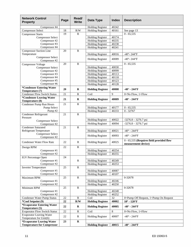
*Condenser Entering Water Temperature (7) 20 R Holding Register 40008 -40° - 244°F
Condenser Flow Switch Status 21 R Coil 9 0=No Flow, 1=Flow *Condenser Leaving Water Temperature (8) 21 R Holding Register 40009 -40° - 244°F
Condenser Pump Run Hours Pump Select
Pump #2
21 R Holding Register 40177 0 - 65,535 Holding Register 40233 0 - 32767
Condenser Refrigerant Pressure
Compressor Select Compressor #2
21 R
Holding Register 40022 -3276.8 – 3276.7 psi Holding Register 40094 -3276.8 – 3276.7 psi
Condenser Saturated Refrigerant Temperature
Compressor Select Compressor #2
21 R Holding Register 40021 -40° - 244°F
Holding Register 40093 -40° - 244°F
Condenser Water Flow Rate 22 R Holding Register 40025 0 - 65,535 (Requires field provided flow measurement device)
Design RPM Compressor #1 Compressor #2
22 R Holding Register 40254
Holding Register 40255 IGV Percentage Open
Compressor #1 Compressor #2
24 R
Holding Register 40249
Holding Register 40253 Inverter Temperature
Compressor #1 Compressor #2
25 R Holding Register 40087 Holding Register 40107
Maximum RPM Compressor #1 Compressor #2
25 R 0-32678 Holding Register 40246 Holding Register 40250
Minimum RPM Compressor #1 Compressor #2
25 R 0-32678 Holding Register 40248 Holding Register 40252
Condenser Water Pump Status 22 R Coil 32 0=Pump Off Request, 1=Pump On Request *Cool Setpoint (9) 22 R/W Holding Register 40002 10 - 120°F *Evaporator Entering Water Temperature (5) 22 R Holding Register 40005 -40° - 244°F
Evaporator Flow Switch Status 22 R Coil 8 0=No Flow, 1=Flow Evaporator Leaving Water Temperature for Unit(6) 22 R Holding Register 40007 -40° - 244°F
*Evaporator Leaving Water Temperature for Compressor
23 R Holding Register 40015 -40° - 244°F
12 ED 15063-5
Network Control Property
Page Read/ Write
Data Type Index Description
Compressor Select Compressor #2
Holding Register 40088 -40° - 244°F
Evaporator Pump Run Hours Pump Select
Pump #2
23 R Holding Register 40176 0 – 65,535 Holding Register 40232 0 – 65,535
Evaporator Refrigerant Pressure
Compressor Select Compressor #2
23 R
Holding Register 40018 -3276.8 – 3276.7 psi Holding Register 40091 -3276.8 – 3276.7 psi
Evaporator Saturated Refrigerant Temperature
Compressor Select Compressor #2
23 R
Holding Register 40017 -40° - 244°F Holding Register 40090 -40° - 244°F
Evaporator Water Flow Rate 24 R Holding Register 40019 0 - 65,535 (Requires field provided flow measurement device)
Evaporator Water Pump Status 24 R Coil 30 0=Pump Off Request, 1=Pump On Request Heat Recovery Entering Water Temperature
24 R Holding Register 40023 -40° - 244°F
Heat Recovery Leaving Water Temperature
24 R Holding Register 40024 -40° - 244°F
Heat Setpoint 24 R/W Holding Register 40006 50° - 120°F Ice Setpoint 24 R/W Holding Register 40051 15 - 35°F, Default=25°F Liquid Line Refrigerant Pressure
25 R Holding Register 40039 -22592 - 22591 psi
Liquid Line Refrigerant Temperature
Compressor Select Compressor #2
25 R
Holding Register 40037 -40°- 244°F Holding Register 40105 -40°- 244°F
Oil Feed Pressure Compressor Select
Compressor #2
26 R Holding Register 40033 -22592 - 22591 psi Holding Register 40101 -22592 - 22591 psi
Oil Feed Temperature Compressor Select
Compressor #2
26 R Holding Register 40035 -40° - 244°F Holding Register 40103 -40° - 244°F
Oil Sump Pressure Compressor Select
Compressor #2
26 R Holding Register 40034 -22592 - 22591 psi Holding Register 40102 -22592 - 22591 psi
Oil Sump Temperature Compressor Select
Compressor #2
26 R Holding Register 40036 -40° - 244°F Holding Register 40104 -40° - 244°F
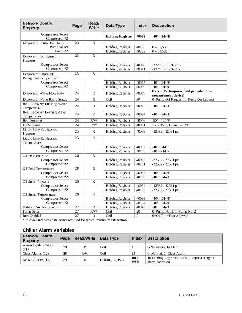
Outdoor Air Temperature 27 R Holding Register 40040 -40° - 244°F Pump Select 27 R/W Coil 20 0=Pump No. 1, 1=Pump No. 2 Run Enabled 27 R Coil 3 0=OFF, 1=Run Allowed *Boldface indicates data points required for typical minimum integration.
Chiller Alarm Variables Network Control Property
Page Read/Write Data Type Index Description
Alarm Digital Output (11) 28 R Coil 4 0-No Alarm, 1=Alarm
Clear Alarms (12) 28 R/W Coil 25 0=Normal, 1=Clear Alarm
Active Alarms (13) 29 R Holding Register 40130-40145
16 Holding Registers: Each bit representing an alarm condition
13 ED 15063-5
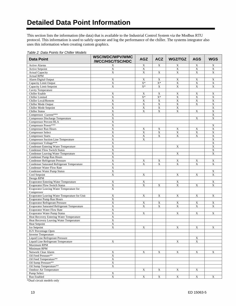
Detailed Data Point Information This section lists the information (the data) that is available to the Industrial Control System via the Modbus RTU protocol. This information is used to safely operate and log the performance of the chiller. The systems integrator also uses this information when creating custom graphics. Table 2: Data Points for Chiller Models
Data Point WSC/WDC/WPV/WMC/WCC/HSC/TSC/HDC
AGZ ACZ WGZ/TGZ AGS WGS
Active Alarms X X X X X X Active Setpoint X X X X X Actual Capacity X X X X X X Actual RPM Alarm Digital Output X X X X X X Capacity Limit Output X X* X* X X X Capacity Limit Setpoint X X* X X X X Cavity Temperature Chiller Enable X X X X X X Chiller Limited X X* X* X X X Chiller Local/Remote X X X X X X Chiller Mode Output X X X X X X Chiller Mode Setpoint X X X X X Chiller Status X X X X X X Compressor Current*** X X Compressor Discharge Temperature X X X Compressor Percent RLA X Compressor Power*** X X Compressor Run Hours X X X X X X Compressor Select X X X X X X Compressor Starts X X X X X X Compressor Suction Line Temperature X X X Compressor Voltage*** X X Condenser Entering Water Temperature X X X Condenser Flow Switch Status X X Condenser Leaving Water Temperature X X X Condenser Pump Run Hours X Condenser Refrigerant Pressure X X X X X X Condenser Saturated Refrigerant Temperature X X X X X X Condenser Water Flow Rate X Condenser Water Pump Status X X Cool Setpoint X X X X X Design RPM Evaporator Entering Water Temperature X X X X Evaporator Flow Switch Status X X X X X X Evaporator Leaving Water Temperature for Compressor
X
Evaporator Leaving Water Temperature for Unit X X X X X X Evaporator Pump Run Hours X Evaporator Refrigerant Pressure X X X X X X Evaporator Saturated Refrigerant Temperature X X X X X X Evaporator Water Flow Rate X Evaporator Water Pump Status X X X X X Heat Recovery Entering Water Temperature X Heat Recovery Leaving Water Temperature X Heat Setpoint X Ice Setpoint X X X X X IGV Percentage Open Inverter Temperature Liquid Line Refrigerant Pressure X Liquid Line Refrigerant Temperature X X X Maximum RPM Minimum RPM Network Clear Alarm X X X X X X Oil Feed Pressure** X Oil Feed Temperature** X Oil Sump Pressure** X Oil Sump Temperature** X Outdoor Air Temperature X X X X Pump Select X Run Enabled X X X X X X
*Dual circuit models only
14 ED 15063-5
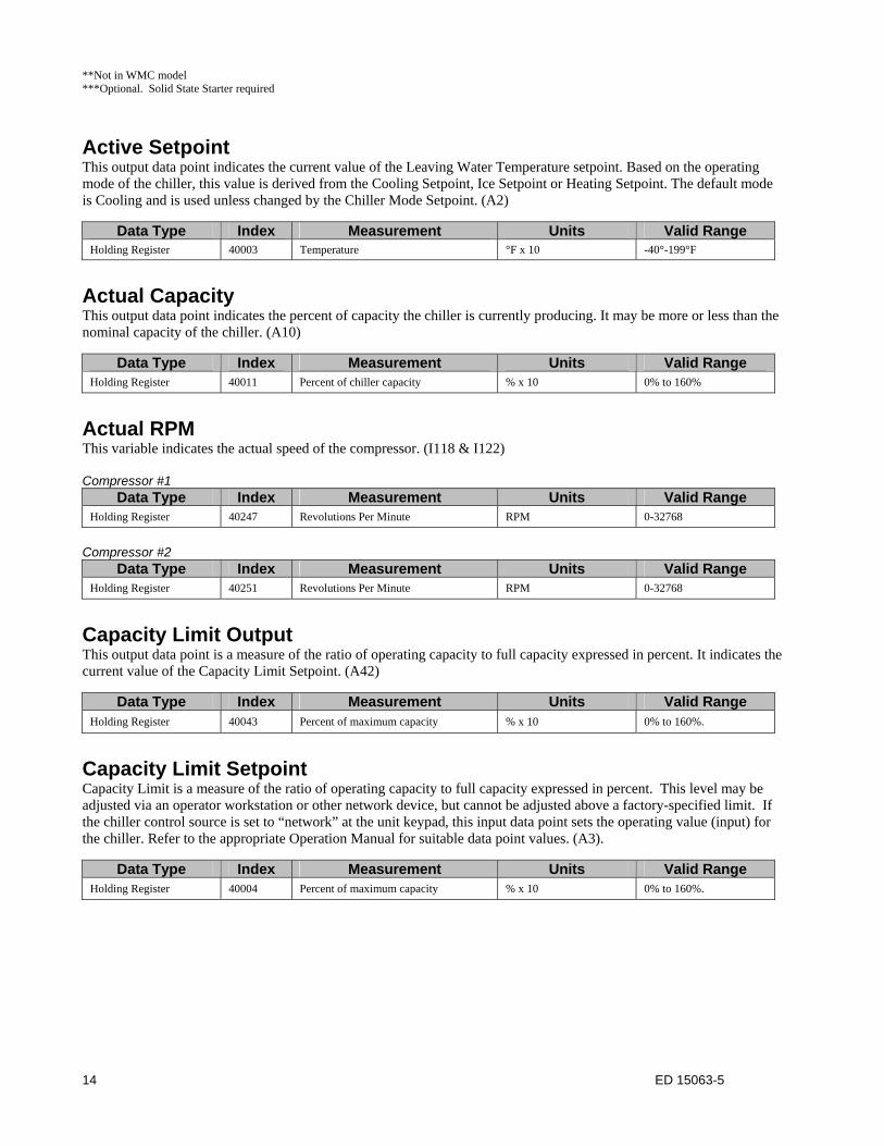
**Not in WMC model ***Optional. Solid State Starter required
Active Setpoint This output data point indicates the current value of the Leaving Water Temperature setpoint. Based on the operating mode of the chiller, this value is derived from the Cooling Setpoint, Ice Setpoint or Heating Setpoint. The default mode is Cooling and is used unless changed by the Chiller Mode Setpoint. (A2)
Data Type Index Measurement Units Valid Range Holding Register 40003 Temperature °F x 10 -40°-199°F
Actual Capacity This output data point indicates the percent of capacity the chiller is currently producing. It may be more or less than the nominal capacity of the chiller. (A10)
Data Type Index Measurement Units Valid Range Holding Register 40011 Percent of chiller capacity % x 10 0% to 160%
Actual RPM This variable indicates the actual speed of the compressor. (I118 & I122) Compressor #1
Data Type Index Measurement Units Valid Range Holding Register 40247 Revolutions Per Minute RPM 0-32768
Compressor #2
Data Type Index Measurement Units Valid Range Holding Register 40251 Revolutions Per Minute RPM 0-32768
Capacity Limit Output This output data point is a measure of the ratio of operating capacity to full capacity expressed in percent. It indicates the current value of the Capacity Limit Setpoint. (A42)
Data Type Index Measurement Units Valid Range Holding Register 40043 Percent of maximum capacity % x 10 0% to 160%.
Capacity Limit Setpoint Capacity Limit is a measure of the ratio of operating capacity to full capacity expressed in percent. This level may be adjusted via an operator workstation or other network device, but cannot be adjusted above a factory-specified limit. If the chiller control source is set to “network” at the unit keypad, this input data point sets the operating value (input) for the chiller. Refer to the appropriate Operation Manual for suitable data point values. (A3).
Data Type Index Measurement Units Valid Range Holding Register 40004 Percent of maximum capacity % x 10 0% to 160%.
15 ED 15063-5
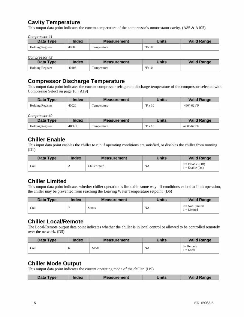
Cavity Temperature This output data point indicates the current temperature of the compressor’s motor stator cavity. (A85 & A105) Compressor #1
Data Type Index Measurement Units Valid Range Holding Register 40086 Temperature °Fx10
Compressor #2
Data Type Index Measurement Units Valid Range Holding Register 40106 Temperature °Fx10
Compressor Discharge Temperature This output data point indicates the current compressor refrigerant discharge temperature of the compressor selected with Compressor Select on page 18. (A19)
Data Type Index Measurement Units Valid Range Holding Register 40020 Temperature °F x 10 -460°-621°F
Compressor #2
Data Type Index Measurement Units Valid Range Holding Register 40092 Temperature °F x 10 -460°-621°F
Chiller Enable This input data point enables the chiller to run if operating conditions are satisfied, or disables the chiller from running. (D1)
Data Type Index Measurement Units Valid Range
Coil 2 Chiller State NA 0 = Disable (Off) 1 = Enable (On)
Chiller Limited This output data point indicates whether chiller operation is limited in some way. If conditions exist that limit operation, the chiller may be prevented from reaching the Leaving Water Temperature setpoint. (D6)
Data Type Index Measurement Units Valid Range
Coil 7 Status NA 0 = Not Limited 1 = Limited
Chiller Local/Remote The Local/Remote output data point indicates whether the chiller is in local control or allowed to be controlled remotely over the network. (D5)
Data Type Index Measurement Units Valid Range
Coil 6 Mode NA 0= Remote 1 = Local
Chiller Mode Output This output data point indicates the current operating mode of the chiller. (I19)
Data Type Index Measurement Units Valid Range
16 ED 15063-5
Holding Register 40148 HVAC Mode NA 1. ICE 2. COOL 3. HEAT
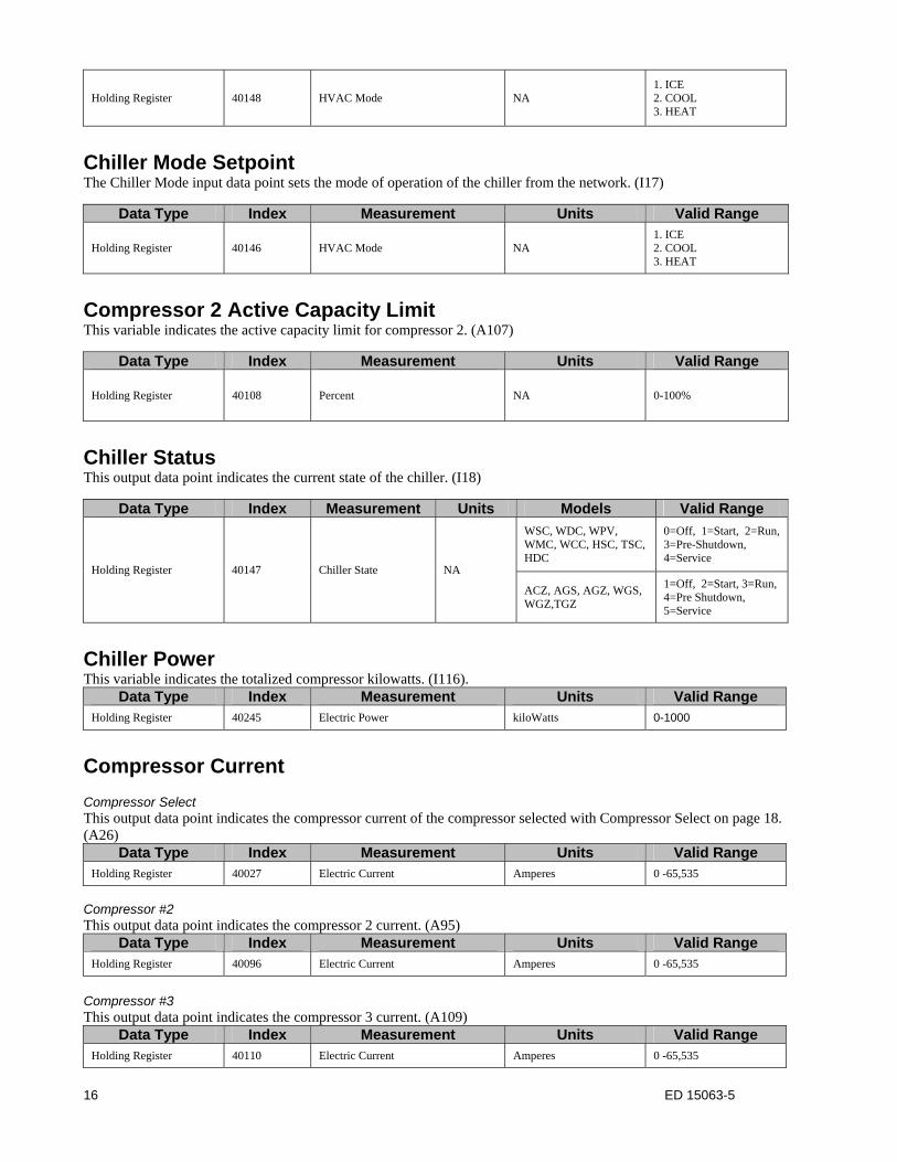
Chiller Mode Setpoint The Chiller Mode input data point sets the mode of operation of the chiller from the network. (I17)
Data Type Index Measurement Units Valid Range
Holding Register 40146 HVAC Mode NA 1. ICE 2. COOL 3. HEAT
Compressor 2 Active Capacity Limit This variable indicates the active capacity limit for compressor 2. (A107)
Data Type Index Measurement Units Valid Range
Holding Register 40108 Percent NA 0-100%
Chiller Status This output data point indicates the current state of the chiller. (I18)
Data Type Index Measurement Units Models Valid Range
Holding Register 40147 Chiller State NA
WSC, WDC, WPV, WMC, WCC, HSC, TSC, HDC
0=Off, 1=Start, 2=Run, 3=Pre-Shutdown, 4=Service
ACZ, AGS, AGZ, WGS, WGZ,TGZ
1=Off, 2=Start, 3=Run, 4=Pre Shutdown, 5=Service
Chiller Power This variable indicates the totalized compressor kilowatts. (I116).
Data Type Index Measurement Units Valid Range Holding Register 40245 Electric Power kiloWatts 0-1000
Compressor Current Compressor Select This output data point indicates the compressor current of the compressor selected with Compressor Select on page 18. (A26)
Data Type Index Measurement Units Valid Range Holding Register 40027 Electric Current Amperes 0 -65,535
Compressor #2 This output data point indicates the compressor 2 current. (A95)
Data Type Index Measurement Units Valid Range Holding Register 40096 Electric Current Amperes 0 -65,535
Compressor #3 This output data point indicates the compressor 3 current. (A109)
Data Type Index Measurement Units Valid Range Holding Register 40110 Electric Current Amperes 0 -65,535
17 ED 15063-5
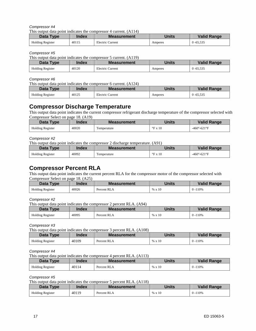
Compressor #4 This output data point indicates the compressor 4 current. (A114)
Data Type Index Measurement Units Valid Range Holding Register 40115 Electric Current Amperes 0 -65,535
Compressor #5 This output data point indicates the compressor 5 current. (A119)
Data Type Index Measurement Units Valid Range Holding Register 40120 Electric Current Amperes 0 -65,535
Compressor #6 This output data point indicates the compressor 6 current. (A124)
Data Type Index Measurement Units Valid Range Holding Register 40125 Electric Current Amperes 0 -65,535
Compressor Discharge Temperature This output data point indicates the current compressor refrigerant discharge temperature of the compressor selected with Compressor Select on page 18. (A19)
Data Type Index Measurement Units Valid Range Holding Register 40020 Temperature °F x 10 -460°-621°F
Compressor #2 This output data point indicates the compressor 2 discharge temperature. (A91)
Data Type Index Measurement Units Valid Range Holding Register 40092 Temperature °F x 10 -460°-621°F
Compressor Percent RLA This output data point indicates the current percent RLA for the compressor motor of the compressor selected with Compressor Select on page 18. (A25)
Data Type Index Measurement Units Valid Range Holding Register 40026 Percent RLA % x 10 0 -110%
Compressor #2 This output data point indicates the compressor 2 percent RLA. (A94)
Data Type Index Measurement Units Valid Range Holding Register 40095 Percent RLA % x 10 0 -110%
Compressor #3 This output data point indicates the compressor 3 percent RLA. (A108)
Data Type Index Measurement Units Valid Range Holding Register 40109 Percent RLA % x 10 0 -110%
Compressor #4 This output data point indicates the compressor 4 percent RLA. (A113)
Data Type Index Measurement Units Valid Range Holding Register 40114 Percent RLA % x 10 0 -110%
Compressor #5 This output data point indicates the compressor 5 percent RLA. (A118)
Data Type Index Measurement Units Valid Range Holding Register 40119 Percent RLA % x 10 0 -110%
18 ED 15063-5
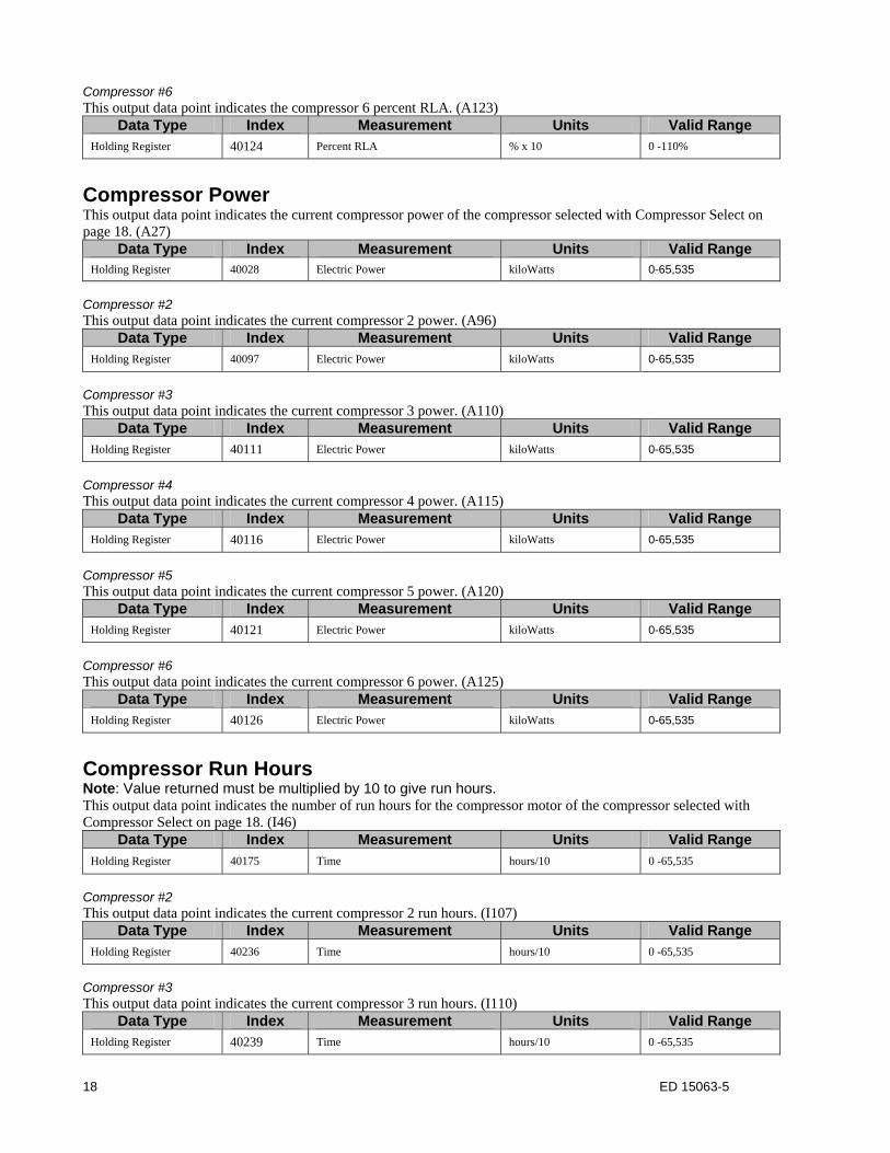
Compressor #6 This output data point indicates the compressor 6 percent RLA. (A123)
Data Type Index Measurement Units Valid Range Holding Register 40124 Percent RLA % x 10 0 -110%
Compressor Power This output data point indicates the current compressor power of the compressor selected with Compressor Select on page 18. (A27)
Data Type Index Measurement Units Valid Range Holding Register 40028 Electric Power kiloWatts 0-65,535
Compressor #2 This output data point indicates the current compressor 2 power. (A96)
Data Type Index Measurement Units Valid Range Holding Register 40097 Electric Power kiloWatts 0-65,535
Compressor #3 This output data point indicates the current compressor 3 power. (A110)
Data Type Index Measurement Units Valid Range Holding Register 40111 Electric Power kiloWatts 0-65,535
Compressor #4 This output data point indicates the current compressor 4 power. (A115)
Data Type Index Measurement Units Valid Range Holding Register 40116 Electric Power kiloWatts 0-65,535
Compressor #5 This output data point indicates the current compressor 5 power. (A120)
Data Type Index Measurement Units Valid Range Holding Register 40121 Electric Power kiloWatts 0-65,535
Compressor #6 This output data point indicates the current compressor 6 power. (A125)
Data Type Index Measurement Units Valid Range Holding Register 40126 Electric Power kiloWatts 0-65,535
Compressor Run Hours Note: Value returned must be multiplied by 10 to give run hours. This output data point indicates the number of run hours for the compressor motor of the compressor selected with Compressor Select on page 18. (I46)
Data Type Index Measurement Units Valid Range
Holding Register 40175 Time hours/10 0 -65,535
Compressor #2 This output data point indicates the current compressor 2 run hours. (I107)
Data Type Index Measurement Units Valid Range Holding Register 40236 Time hours/10 0 -65,535
Compressor #3 This output data point indicates the current compressor 3 run hours. (I110)
Data Type Index Measurement Units Valid Range Holding Register 40239 Time hours/10 0 -65,535
19 ED 15063-5
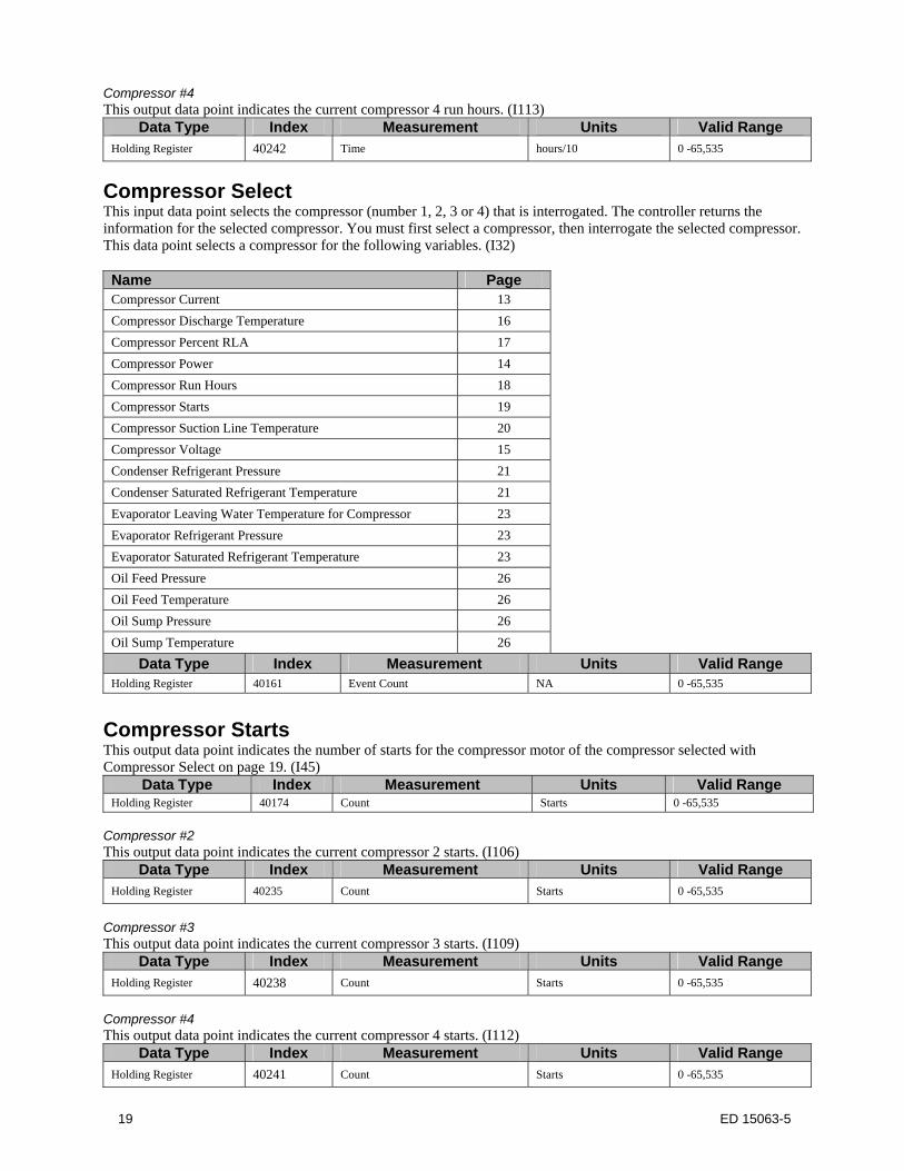
Compressor #4 This output data point indicates the current compressor 4 run hours. (I113)
Data Type Index Measurement Units Valid Range Holding Register 40242 Time hours/10 0 -65,535
Compressor Select This input data point selects the compressor (number 1, 2, 3 or 4) that is interrogated. The controller returns the information for the selected compressor. You must first select a compressor, then interrogate the selected compressor. This data point selects a compressor for the following variables. (I32) Name Page Compressor Current 13
Compressor Discharge Temperature 16
Compressor Percent RLA 17
Compressor Power 14
Compressor Run Hours 18
Compressor Starts 19
Compressor Suction Line Temperature 20
Compressor Voltage 15
Condenser Refrigerant Pressure 21
Condenser Saturated Refrigerant Temperature 21
Evaporator Leaving Water Temperature for Compressor 23
Evaporator Refrigerant Pressure 23
Evaporator Saturated Refrigerant Temperature 23
Oil Feed Pressure 26
Oil Feed Temperature 26
Oil Sump Pressure 26
Oil Sump Temperature 26
Data Type Index Measurement Units Valid Range Holding Register 40161 Event Count NA 0 -65,535
Compressor Starts This output data point indicates the number of starts for the compressor motor of the compressor selected with Compressor Select on page 19. (I45)
Data Type Index Measurement Units Valid Range Holding Register 40174 Count Starts 0 -65,535
Compressor #2 This output data point indicates the current compressor 2 starts. (I106)
Data Type Index Measurement Units Valid Range Holding Register 40235 Count Starts 0 -65,535
Compressor #3 This output data point indicates the current compressor 3 starts. (I109)
Data Type Index Measurement Units Valid Range Holding Register 40238 Count Starts 0 -65,535
Compressor #4 This output data point indicates the current compressor 4 starts. (I112)
Data Type Index Measurement Units Valid Range Holding Register 40241 Count Starts 0 -65,535
20 ED 15063-5
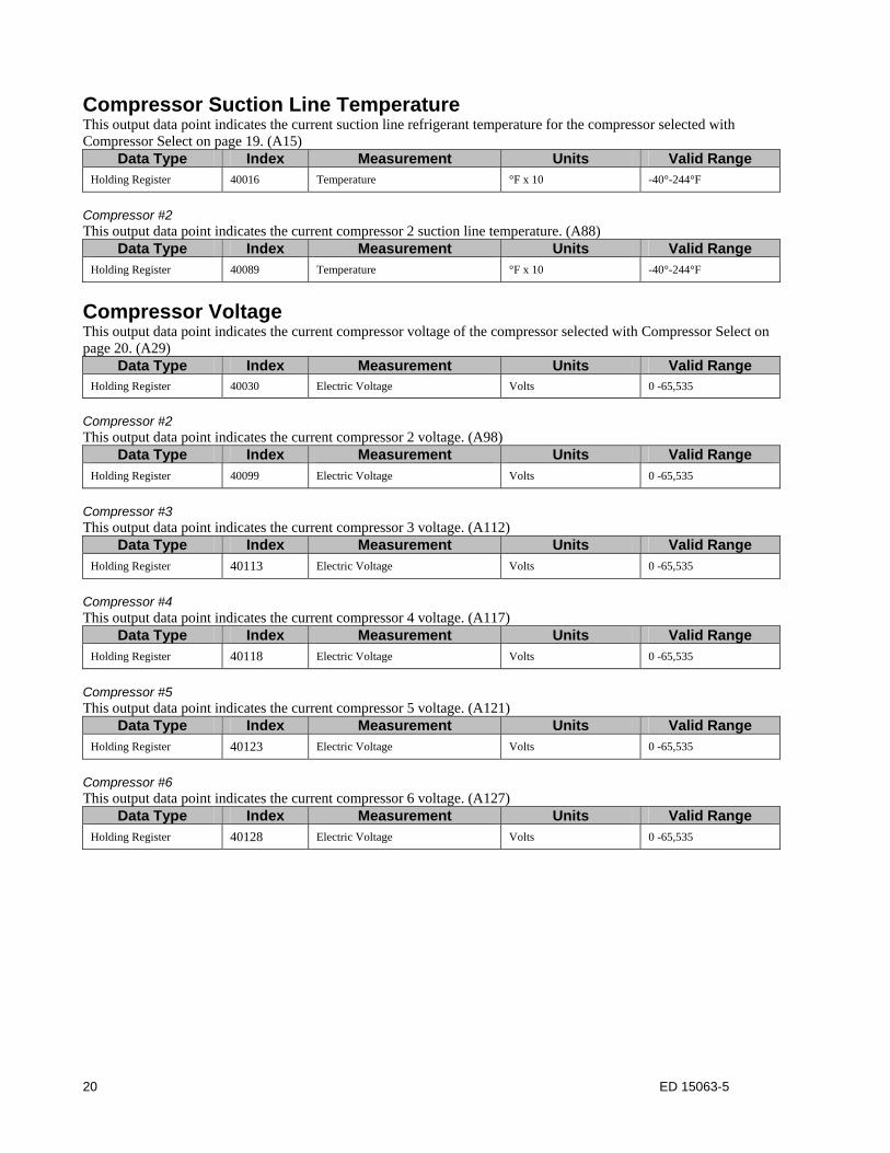
Compressor Suction Line Temperature This output data point indicates the current suction line refrigerant temperature for the compressor selected with Compressor Select on page 19. (A15)
Data Type Index Measurement Units Valid Range Holding Register 40016 Temperature °F x 10 -40°-244°F
Compressor #2 This output data point indicates the current compressor 2 suction line temperature. (A88)
Data Type Index Measurement Units Valid Range Holding Register 40089 Temperature °F x 10 -40°-244°F
Compressor Voltage This output data point indicates the current compressor voltage of the compressor selected with Compressor Select on page 20. (A29)
Data Type Index Measurement Units Valid Range Holding Register 40030 Electric Voltage Volts 0 -65,535
Compressor #2 This output data point indicates the current compressor 2 voltage. (A98)
Data Type Index Measurement Units Valid Range Holding Register 40099 Electric Voltage Volts 0 -65,535
Compressor #3 This output data point indicates the current compressor 3 voltage. (A112)
Data Type Index Measurement Units Valid Range Holding Register 40113 Electric Voltage Volts 0 -65,535
Compressor #4 This output data point indicates the current compressor 4 voltage. (A117)
Data Type Index Measurement Units Valid Range Holding Register 40118 Electric Voltage Volts 0 -65,535
Compressor #5 This output data point indicates the current compressor 5 voltage. (A121)
Data Type Index Measurement Units Valid Range Holding Register 40123 Electric Voltage Volts 0 -65,535
Compressor #6 This output data point indicates the current compressor 6 voltage. (A127)
Data Type Index Measurement Units Valid Range Holding Register 40128 Electric Voltage Volts 0 -65,535
21 ED 15063-5
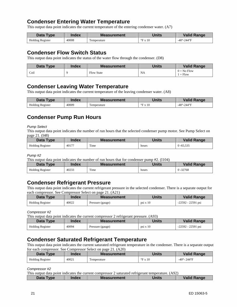
Condenser Entering Water Temperature This output data point indicates the current temperature of the entering condenser water. (A7)
Data Type Index Measurement Units Valid Range Holding Register 40008 Temperature °F x 10 -40°-244°F
Condenser Flow Switch Status This output data point indicates the status of the water flow through the condenser. (D8)
Data Type Index Measurement Units Valid Range
Coil 9 Flow State NA 0 = No Flow 1 = Flow
Condenser Leaving Water Temperature This output data point indicates the current temperature of the leaving condenser water. (A8)
Data Type Index Measurement Units Valid Range Holding Register 40009 Temperature °F x 10 -40°-244°F
Condenser Pump Run Hours Pump Select This output data point indicates the number of run hours that the selected condenser pump motor. See Pump Select on page 21. (I48)
Data Type Index Measurement Units Valid Range Holding Register 40177 Time hours 0 -65,535
Pump #2 This output data point indicates the number of run hours that for condenser pump #2. (I104)
Data Type Index Measurement Units Valid Range Holding Register 40233 Time hours 0 -32768
Condenser Refrigerant Pressure This output data point indicates the current refrigerant pressure in the selected condenser. There is a separate output for each compressor. See Compressor Select on page 21. (A21)
Data Type Index Measurement Units Valid Range Holding Register 40022 Pressure (gauge) psi x 10 -22592 - 22591 psi
Compressor #2 This output data point indicates the current compressor 2 refrigerant pressure. (A93)
Data Type Index Measurement Units Valid Range Holding Register 40094 Pressure (gauge) psi x 10 -22592 - 22591 psi
Condenser Saturated Refrigerant Temperature This output data point indicates the current saturated refrigerant temperature in the condenser. There is a separate output for each compressor. See Compressor Select on page 21. (A20)
Data Type Index Measurement Units Valid Range Holding Register 40021 Temperature °F x 10 -40°- 244°F
Compressor #2 This output data point indicates the current compressor 2 saturated refrigerant temperature. (A92)
Data Type Index Measurement Units Valid Range
22 ED 15063-5
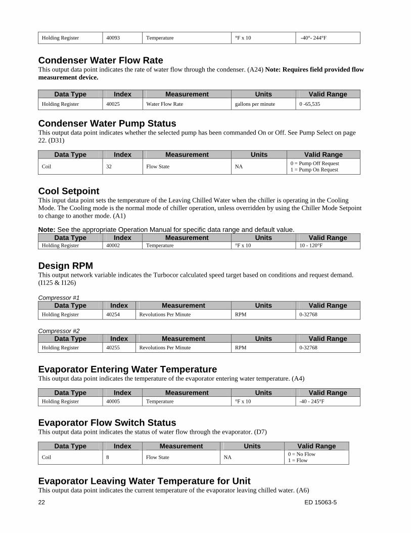
Holding Register 40093 Temperature °F x 10 -40°- 244°F
Condenser Water Flow Rate This output data point indicates the rate of water flow through the condenser. (A24) Note: Requires field provided flow measurement device.
Data Type Index Measurement Units Valid Range Holding Register 40025 Water Flow Rate gallons per minute 0 -65,535
Condenser Water Pump Status This output data point indicates whether the selected pump has been commanded On or Off. See Pump Select on page 22. (D31)
Data Type Index Measurement Units Valid Range
Coil 32 Flow State NA 0 = Pump Off Request 1 = Pump On Request
Cool Setpoint This input data point sets the temperature of the Leaving Chilled Water when the chiller is operating in the Cooling Mode. The Cooling mode is the normal mode of chiller operation, unless overridden by using the Chiller Mode Setpoint to change to another mode. (A1)
Note: See the appropriate Operation Manual for specific data range and default value. Data Type Index Measurement Units Valid Range
Holding Register 40002 Temperature °F x 10 10 - 120°F
Design RPM This output network variable indicates the Turbocor calculated speed target based on conditions and request demand. (I125 & I126) Compressor #1
Data Type Index Measurement Units Valid Range Holding Register 40254 Revolutions Per Minute RPM 0-32768
Compressor #2
Data Type Index Measurement Units Valid Range Holding Register 40255 Revolutions Per Minute RPM 0-32768
Evaporator Entering Water Temperature This output data point indicates the temperature of the evaporator entering water temperature. (A4)
Data Type Index Measurement Units Valid Range Holding Register 40005 Temperature °F x 10 -40 - 245°F
Evaporator Flow Switch Status This output data point indicates the status of water flow through the evaporator. (D7)
Data Type Index Measurement Units Valid Range
Coil 8 Flow State NA 0 = No Flow 1 = Flow
Evaporator Leaving Water Temperature for Unit This output data point indicates the current temperature of the evaporator leaving chilled water. (A6)

23 ED 15063-5
Data Type Index Measurement Units Valid Range Holding Register 40007 Temperature °F x 10 -40° - 244°F
Evaporator Leaving Water Temperature for Compressor Compressor Select This output data point indicates the current temperature of the evaporator leaving chilled water temperature of the compressor selected with Compressor Select on page 18. (A14)
Data Type Index Measurement Units Valid Range Holding Register 40015 Temperature °F x 10 -40°-244°F
Compressor #2 This output data point indicates the current temperature of the evaporator leaving chilled water temperature for compressor 2. (A87)
Data Type Index Measurement Units Valid Range Holding Register 40088 Temperature °F x 10 -40°-244°F
Evaporator Pump Run Hours Pump Select This output data point indicates the number of run hours for the selected evaporator pump. There is a separate output for each pump. See Pump Select on page 27. (I47)
Data Type Index Measurement Units Valid Range Holding Register 40176 Event Count Hours 0 - 65,535
Pump #2 This output data point indicates the number of run hours for evaporator pump #2. (I103)
Data Type Index Measurement Units Valid Range Holding Register 40232 Event Count Hours 0 - 65,535
Evaporator Refrigerant Pressure Compressor Select This output data point indicates the current refrigerant pressure in the evaporator. There is a separate output for each compressor. See Compressor Select on page 18. (A17)
Data Type Index Measurement Units Valid Range Holding Register 40018 Pressure (gauge) psi x 10 -22592 - 22591 psi
Compressor #2 This output data point indicates the current refrigerant pressure in the evaporator for compressor 2. (A90)
Data Type Index Measurement Units Valid Range Holding Register 40091 Pressure (gauge) psi x 10 -22592 - 22591 psi
Evaporator Saturated Refrigerant Temperature Compressor Select This output data point indicates the current saturated refrigerant temperature in the evaporator. There is a separate output for each compressor. See Compressor Select on page 18. (A16)
Data Type Index Measurement Units Valid Range Holding Register 40017 Temperature °F x 10 -40° - 244°F
24 ED 15063-5
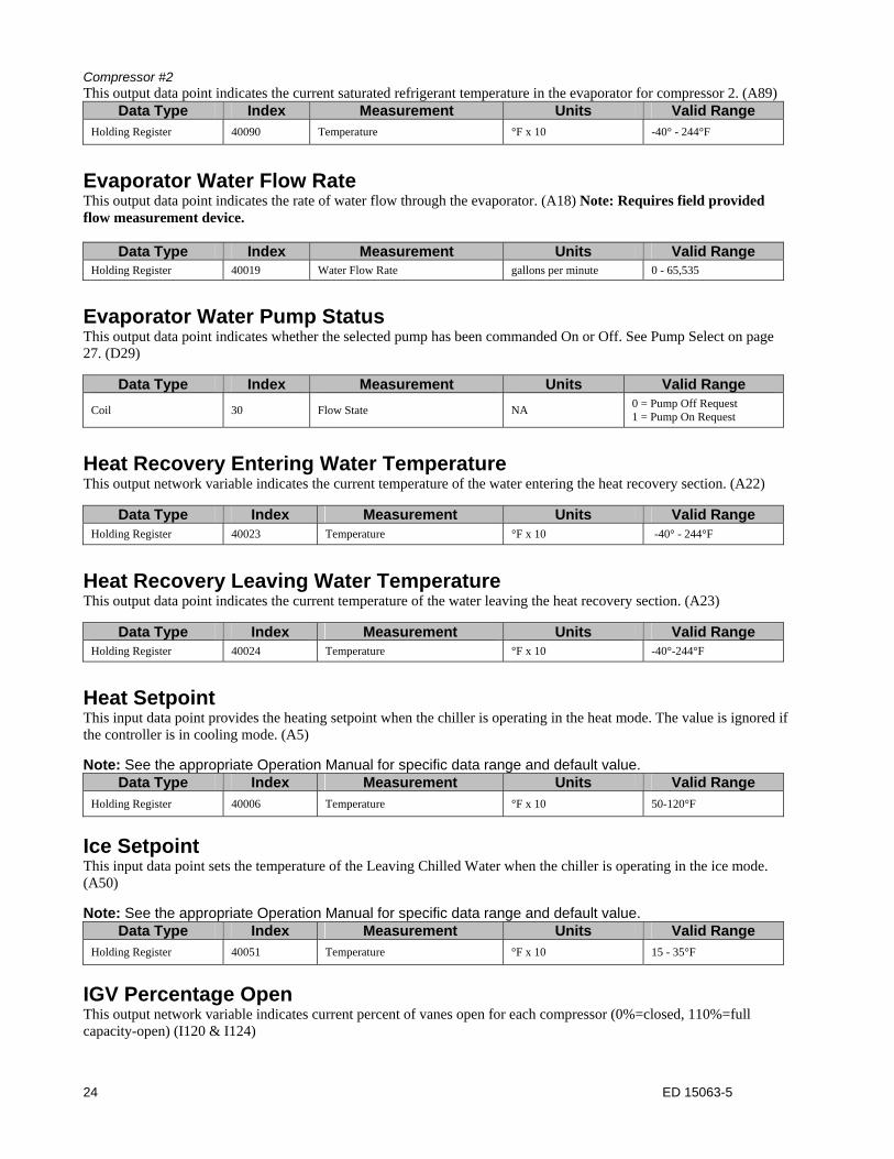
Compressor #2 This output data point indicates the current saturated refrigerant temperature in the evaporator for compressor 2. (A89)
Data Type Index Measurement Units Valid Range Holding Register 40090 Temperature °F x 10 -40° - 244°F
Evaporator Water Flow Rate This output data point indicates the rate of water flow through the evaporator. (A18) Note: Requires field provided flow measurement device.
Data Type Index Measurement Units Valid Range Holding Register 40019 Water Flow Rate gallons per minute 0 - 65,535
Evaporator Water Pump Status This output data point indicates whether the selected pump has been commanded On or Off. See Pump Select on page 27. (D29)
Data Type Index Measurement Units Valid Range
Coil 30 Flow State NA 0 = Pump Off Request 1 = Pump On Request
Heat Recovery Entering Water Temperature This output network variable indicates the current temperature of the water entering the heat recovery section. (A22)
Data Type Index Measurement Units Valid Range Holding Register 40023 Temperature °F x 10 -40° - 244°F
Heat Recovery Leaving Water Temperature This output data point indicates the current temperature of the water leaving the heat recovery section. (A23)
Data Type Index Measurement Units Valid Range Holding Register 40024 Temperature °F x 10 -40°-244°F
Heat Setpoint This input data point provides the heating setpoint when the chiller is operating in the heat mode. The value is ignored if the controller is in cooling mode. (A5)
Note: See the appropriate Operation Manual for specific data range and default value. Data Type Index Measurement Units Valid Range
Holding Register 40006 Temperature °F x 10 50-120°F
Ice Setpoint This input data point sets the temperature of the Leaving Chilled Water when the chiller is operating in the ice mode. (A50)
Note: See the appropriate Operation Manual for specific data range and default value. Data Type Index Measurement Units Valid Range
Holding Register 40051 Temperature °F x 10 15 - 35°F
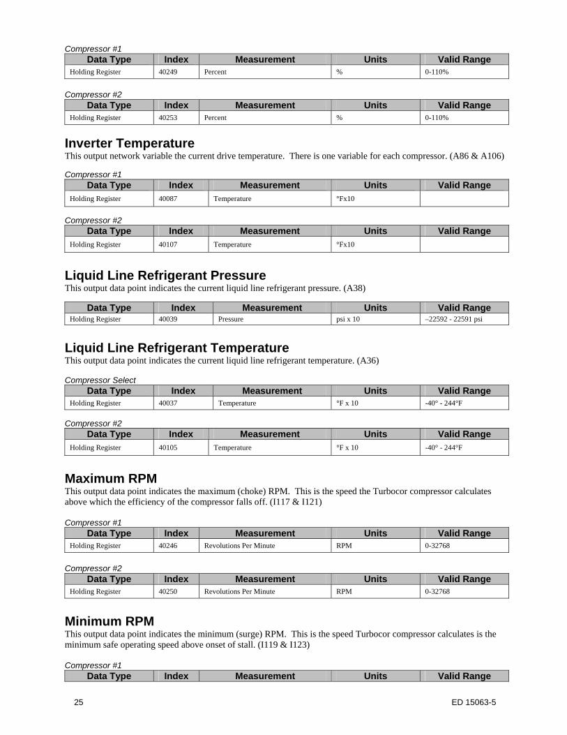
IGV Percentage Open This output network variable indicates current percent of vanes open for each compressor (0%=closed, 110%=full capacity-open) (I120 & I124)
25 ED 15063-5
Compressor #1 Data Type Index Measurement Units Valid Range
Holding Register 40249 Percent % 0-110%
Compressor #2
Data Type Index Measurement Units Valid Range Holding Register 40253 Percent % 0-110%
Inverter Temperature This output network variable the current drive temperature. There is one variable for each compressor. (A86 & A106) Compressor #1
Data Type Index Measurement Units Valid Range Holding Register 40087 Temperature °Fx10
Compressor #2
Data Type Index Measurement Units Valid Range Holding Register 40107 Temperature °Fx10
Liquid Line Refrigerant Pressure This output data point indicates the current liquid line refrigerant pressure. (A38)
Data Type Index Measurement Units Valid Range Holding Register 40039 Pressure psi x 10 –22592 - 22591 psi
Liquid Line Refrigerant Temperature This output data point indicates the current liquid line refrigerant temperature. (A36) Compressor Select
Data Type Index Measurement Units Valid Range Holding Register 40037 Temperature °F x 10 -40° - 244°F
Compressor #2
Data Type Index Measurement Units Valid Range Holding Register 40105 Temperature °F x 10 -40° - 244°F
Maximum RPM This output data point indicates the maximum (choke) RPM. This is the speed the Turbocor compressor calculates above which the efficiency of the compressor falls off. (I117 & I121) Compressor #1
Data Type Index Measurement Units Valid Range Holding Register 40246 Revolutions Per Minute RPM 0-32768
Compressor #2
Data Type Index Measurement Units Valid Range Holding Register 40250 Revolutions Per Minute RPM 0-32768
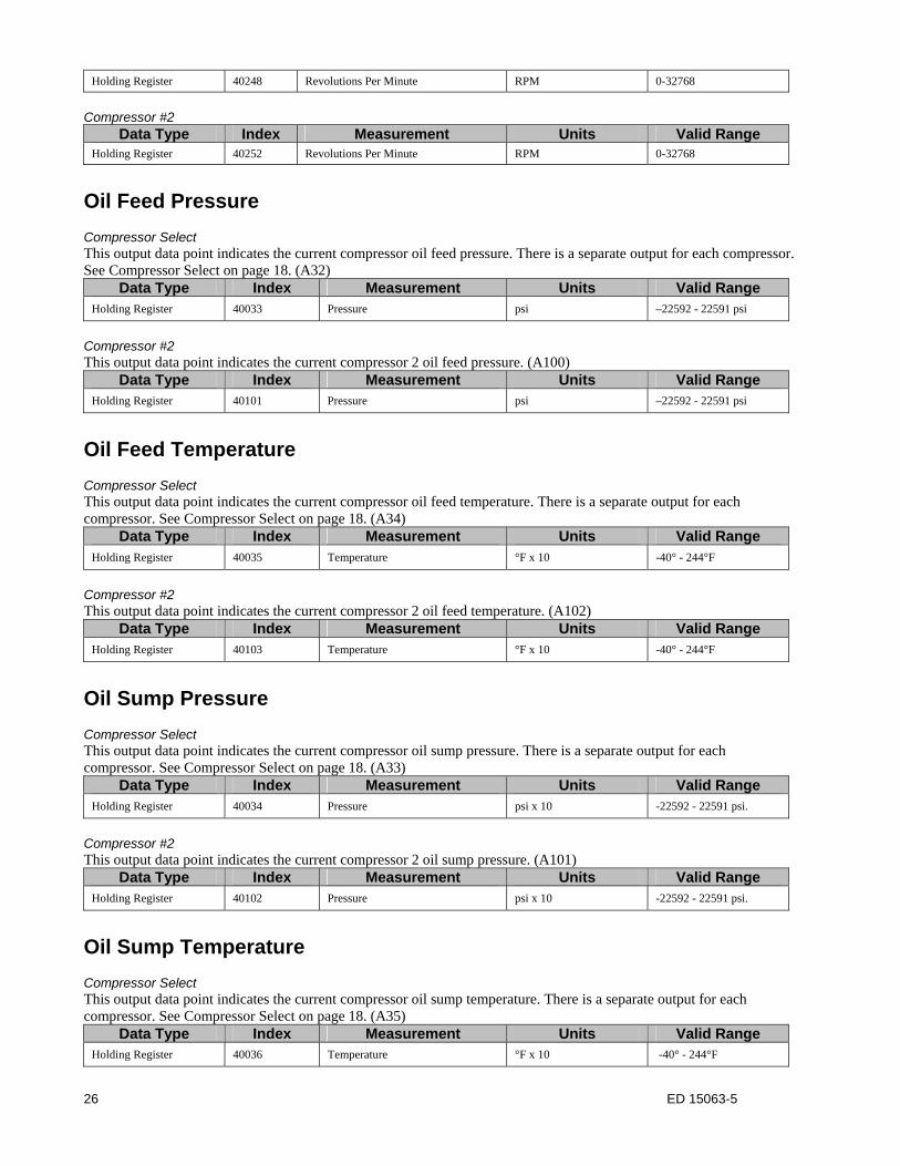
Minimum RPM This output data point indicates the minimum (surge) RPM. This is the speed Turbocor compressor calculates is the minimum safe operating speed above onset of stall. (I119 & I123) Compressor #1
Data Type Index Measurement Units Valid Range
26 ED 15063-5
Holding Register 40248 Revolutions Per Minute RPM 0-32768
Compressor #2
Data Type Index Measurement Units Valid Range Holding Register 40252 Revolutions Per Minute RPM 0-32768
Oil Feed Pressure Compressor Select This output data point indicates the current compressor oil feed pressure. There is a separate output for each compressor. See Compressor Select on page 18. (A32)
Data Type Index Measurement Units Valid Range Holding Register 40033 Pressure psi –22592 - 22591 psi
Compressor #2 This output data point indicates the current compressor 2 oil feed pressure. (A100)
Data Type Index Measurement Units Valid Range Holding Register 40101 Pressure psi –22592 - 22591 psi
Oil Feed Temperature Compressor Select This output data point indicates the current compressor oil feed temperature. There is a separate output for each compressor. See Compressor Select on page 18. (A34)
Data Type Index Measurement Units Valid Range Holding Register 40035 Temperature °F x 10 -40° - 244°F
Compressor #2 This output data point indicates the current compressor 2 oil feed temperature. (A102)
Data Type Index Measurement Units Valid Range Holding Register 40103 Temperature °F x 10 -40° - 244°F
Oil Sump Pressure Compressor Select This output data point indicates the current compressor oil sump pressure. There is a separate output for each compressor. See Compressor Select on page 18. (A33)
Data Type Index Measurement Units Valid Range Holding Register 40034 Pressure psi x 10 -22592 - 22591 psi.
Compressor #2 This output data point indicates the current compressor 2 oil sump pressure. (A101)
Data Type Index Measurement Units Valid Range Holding Register 40102 Pressure psi x 10 -22592 - 22591 psi.
Oil Sump Temperature Compressor Select This output data point indicates the current compressor oil sump temperature. There is a separate output for each compressor. See Compressor Select on page 18. (A35)
Data Type Index Measurement Units Valid Range Holding Register 40036 Temperature °F x 10 -40° - 244°F
27 ED 15063-5
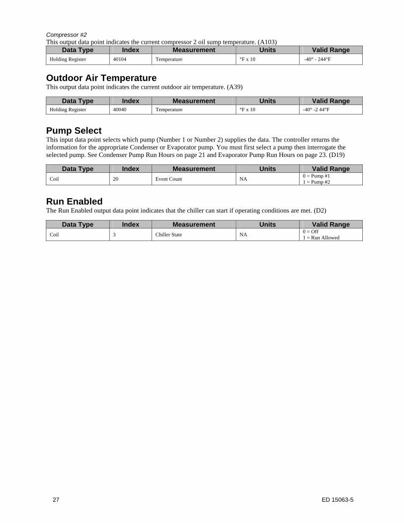
Compressor #2 This output data point indicates the current compressor 2 oil sump temperature. (A103)
Data Type Index Measurement Units Valid Range Holding Register 40104 Temperature °F x 10 -40° - 244°F
Outdoor Air Temperature This output data point indicates the current outdoor air temperature. (A39)
Data Type Index Measurement Units Valid Range Holding Register 40040 Temperature °F x 10 -40° -2 44°F
Pump Select This input data point selects which pump (Number 1 or Number 2) supplies the data. The controller returns the information for the appropriate Condenser or Evaporator pump. You must first select a pump then interrogate the selected pump. See Condenser Pump Run Hours on page 21 and Evaporator Pump Run Hours on page 23. (D19)
Data Type Index Measurement Units Valid Range
Coil 20 Event Count NA 0 = Pump #1 1 = Pump #2
Run Enabled The Run Enabled output data point indicates that the chiller can start if operating conditions are met. (D2)
Data Type Index Measurement Units Valid Range
Coil 3 Chiller State NA 0 = Off 1 = Run Allowed
28 ED 15063-5
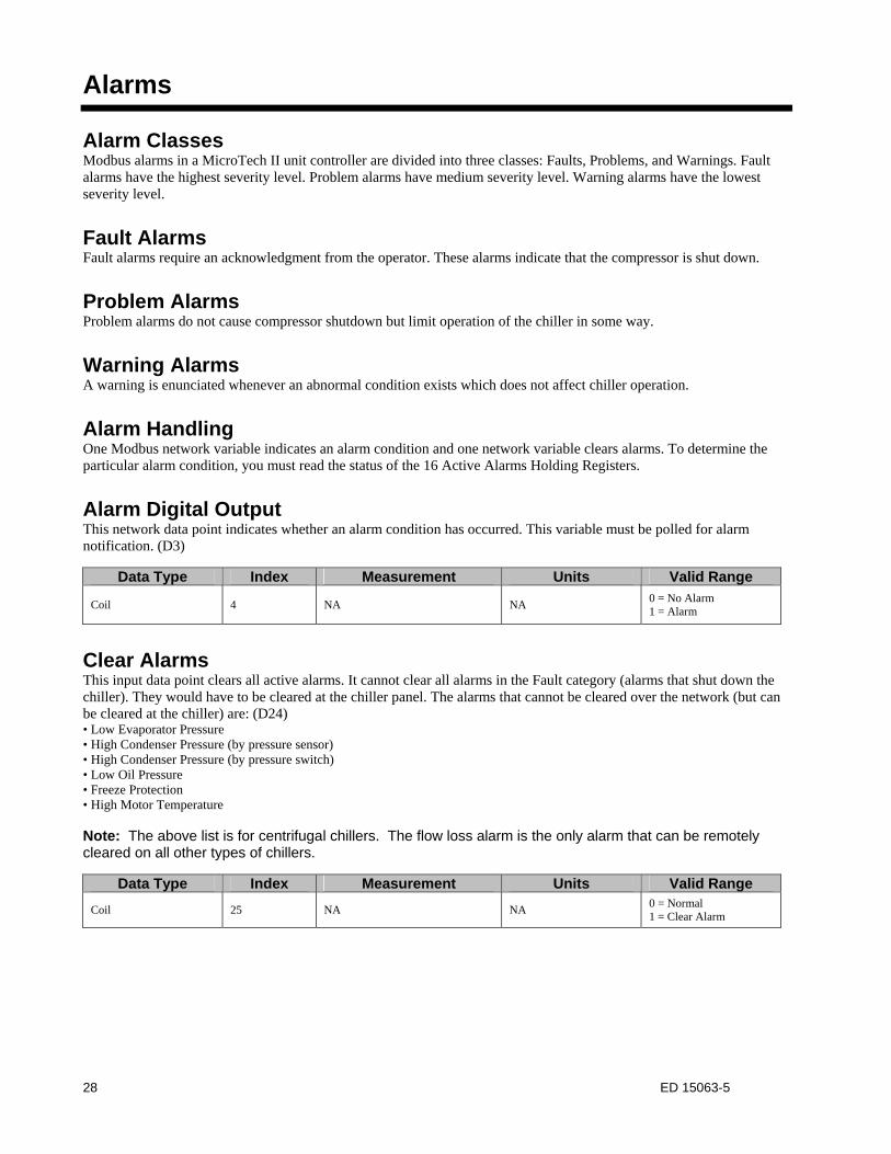
Alarms
Alarm Classes Modbus alarms in a MicroTech II unit controller are divided into three classes: Faults, Problems, and Warnings. Fault alarms have the highest severity level. Problem alarms have medium severity level. Warning alarms have the lowest severity level.
Fault Alarms Fault alarms require an acknowledgment from the operator. These alarms indicate that the compressor is shut down.
Problem Alarms Problem alarms do not cause compressor shutdown but limit operation of the chiller in some way.
Warning Alarms A warning is enunciated whenever an abnormal condition exists which does not affect chiller operation.
Alarm Handling One Modbus network variable indicates an alarm condition and one network variable clears alarms. To determine the particular alarm condition, you must read the status of the 16 Active Alarms Holding Registers.
Alarm Digital Output This network data point indicates whether an alarm condition has occurred. This variable must be polled for alarm notification. (D3)
Data Type Index Measurement Units Valid Range
Coil 4 NA NA 0 = No Alarm 1 = Alarm
Clear Alarms This input data point clears all active alarms. It cannot clear all alarms in the Fault category (alarms that shut down the chiller). They would have to be cleared at the chiller panel. The alarms that cannot be cleared over the network (but can be cleared at the chiller) are: (D24) • Low Evaporator Pressure • High Condenser Pressure (by pressure sensor) • High Condenser Pressure (by pressure switch) • Low Oil Pressure • Freeze Protection • High Motor Temperature Note: The above list is for centrifugal chillers. The flow loss alarm is the only alarm that can be remotely cleared on all other types of chillers.
Data Type Index Measurement Units Valid Range
Coil 25 NA NA 0 = Normal 1 = Clear Alarm
29 ED 15063-5
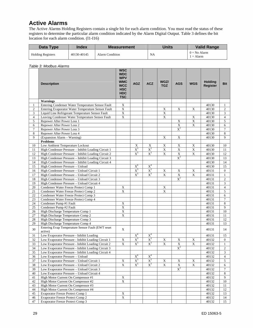
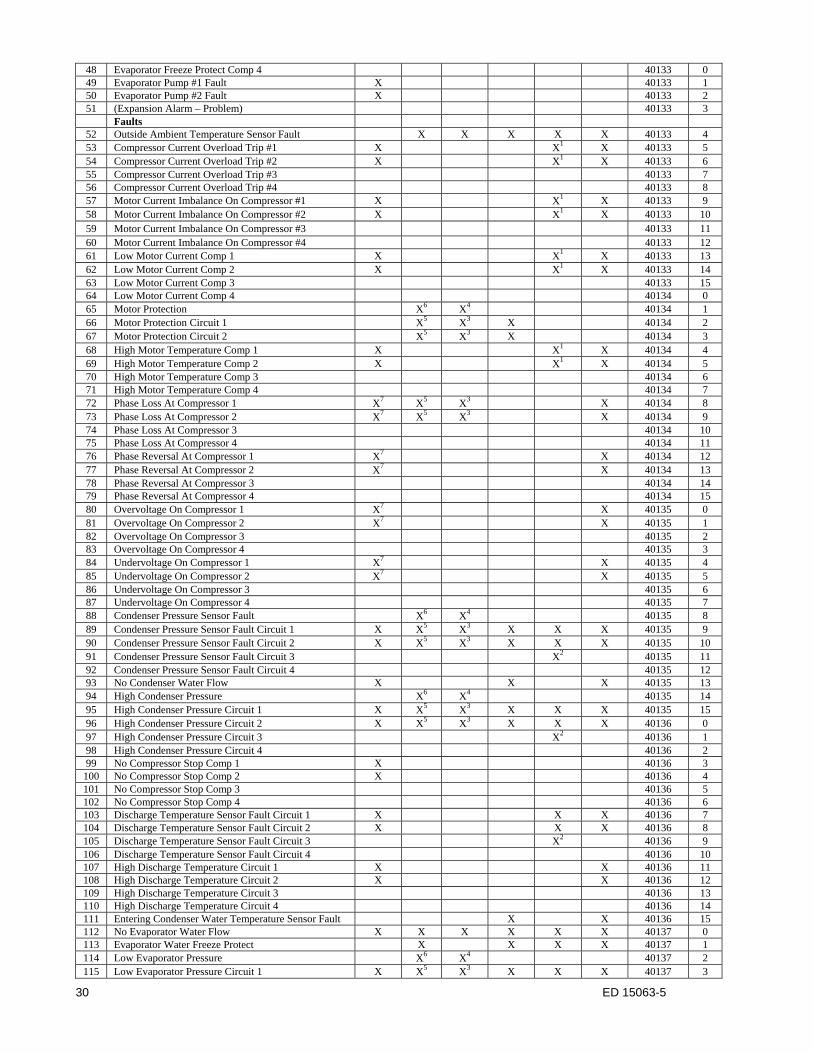
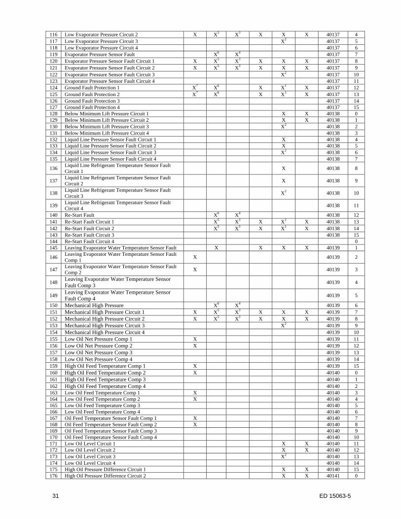
Active Alarms The Active Alarms Holding Registers contain a single bit for each alarm condition. You must read the status of these registers to determine the particular alarm condition indicated by the Alarm Digital Output. Table 3 defines the bit location for each alarm condition. (I1-I16)
Data Type Index Measurement Units Valid Range
Holding Registers 40130-40145 Alarm Condition NA 0 = No Alarm 1 = Alarm
Table 3: Modbus Alarms
Description
WSC WDC WPV WMC WCC HSC HDC TSC
AGZ ACZ WGZ/TGZ
AGS WGS Holding Register
Bit
Warnings 1 Entering Condenser Water Temperature Sensor Fault X 40130 1 2 Entering Evaporator Water Temperature Sensor Fault X X X X 40130 2 3 Liquid Line Refrigerant Temperature Sensor Fault X X 40130 3 4 Leaving Condenser Water Temperature Sensor Fault X X X 40130 4 5 Repower After Power Loss 1 X X 40130 5 6 Repower After Power Loss 2 X X 40130 6 7 Repower After Power Loss 3 X2 40130 7 8 Repower After Power Loss 4 40130 8 9 (Expansion Alarm – Warning) X X 40130 9 Problems
10 Low Ambient Temperature Lockout X X X X X 40130 10 11 High Condenser Pressure – Inhibit Loading Circuit 1 X5 X3 X X X 40130 11 12 High Condenser Pressure – Inhibit Loading Circuit 2 X5 X3 X X X 40130 12 13 High Condenser Pressure – Inhibit Loading Circuit 3 X2 40130 13 14 High Condenser Pressure – Inhibit Loading Circuit 4 40130 14 15 High Condenser Pressure – Unload X6 X4 40130 15 16 High Condenser Pressure – Unload Circuit 1 X5 X3 X X X 40131 0 17 High Condenser Pressure – Unload Circuit 2 X5 X3 X X X 40131 1 18 High Condenser Pressure – Unload Circuit 3 X2 40131 2 19 High Condenser Pressure – Unload Circuit 4 40131 3 20 Condenser Water Freeze Protect Comp 1 X X 40131 4 21 Condenser Water Freeze Protect Comp 2 X X 40131 5 22 Condenser Water Freeze Protect Comp 3 40131 6 23 Condenser Water Freeze Protect Comp 4 40131 7 24 Condenser Pump #1 Fault X 40131 8 25 Condenser Pump #2 Fault X 40131 9 26 High Discharge Temperature Comp 1 X 40131 10 27 High Discharge Temperature Comp 2 X 40131 11 28 High Discharge Temperature Comp 3 40131 12 29 High Discharge Temperature Comp 4 40131 13
30 Entering Evap Temperature Sensor Fault (EWT reset active)
X 40131 14
31 Low Evaporator Pressure - Inhibit Loading X6 X4 40131 15 32 Low Evaporator Pressure - Inhibit Loading Circuit 1 X X5 X3 X X X 40132 0 33 Low Evaporator Pressure - Inhibit Loading Circuit 2 X X5 X3 X X X 40132 1 34 Low Evaporator Pressure - Inhibit Loading Circuit 3 X2 40132 2 35 Low Evaporator Pressure - Inhibit Loading Circuit 4 40132 3 36 Low Evaporator Pressure – Unload X6 X4 40132 4 37 Low Evaporator Pressure – Unload Circuit 1 X X5 X3 X X X 40132 5 38 Low Evaporator Pressure – Unload Circuit 2 X X5 X3 X X X 40132 6 39 Low Evaporator Pressure – Unload Circuit 3 X2 40132 7 40 Low Evaporator Pressure – Unload Circuit 4 40132 8 41 High Motor Current On Compressor #1 X 40132 9 42 High Motor Current On Compressor #2 X 40132 10 43 High Motor Current On Compressor #3 40132 11 44 High Motor Current On Compressor #4 40132 12 45 Evaporator Freeze Protect Comp 1 X 40132 13 46 Evaporator Freeze Protect Comp 2 X 40132 14 47 Evaporator Freeze Protect Comp 3 40132 15
30 ED 15063-5
48 Evaporator Freeze Protect Comp 4 40133 0 49 Evaporator Pump #1 Fault X 40133 1 50 Evaporator Pump #2 Fault X 40133 2 51 (Expansion Alarm – Problem) 40133 3
Faults 52 Outside Ambient Temperature Sensor Fault X X X X X 40133 4 53 Compressor Current Overload Trip #1 X X1 X 40133 5 54 Compressor Current Overload Trip #2 X X1 X 40133 6 55 Compressor Current Overload Trip #3 40133 7 56 Compressor Current Overload Trip #4 40133 8 57 Motor Current Imbalance On Compressor #1 X X1 X 40133 9 58 Motor Current Imbalance On Compressor #2 X X1 X 40133 10 59 Motor Current Imbalance On Compressor #3 40133 11 60 Motor Current Imbalance On Compressor #4 40133 12 61 Low Motor Current Comp 1 X X1 X 40133 13 62 Low Motor Current Comp 2 X X1 X 40133 14 63 Low Motor Current Comp 3 40133 15 64 Low Motor Current Comp 4 40134 0 65 Motor Protection X6 X4 40134 1 66 Motor Protection Circuit 1 X5 X3 X 40134 2 67 Motor Protection Circuit 2 X5 X3 X 40134 3 68 High Motor Temperature Comp 1 X X1 X 40134 4 69 High Motor Temperature Comp 2 X X1 X 40134 5 70 High Motor Temperature Comp 3 40134 6 71 High Motor Temperature Comp 4 40134 7 72 Phase Loss At Compressor 1 X7 X5 X3 X 40134 8 73 Phase Loss At Compressor 2 X7 X5 X3 X 40134 9 74 Phase Loss At Compressor 3 40134 10 75 Phase Loss At Compressor 4 40134 11 76 Phase Reversal At Compressor 1 X7 X 40134 12 77 Phase Reversal At Compressor 2 X7 X 40134 13 78 Phase Reversal At Compressor 3 40134 14 79 Phase Reversal At Compressor 4 40134 15 80 Overvoltage On Compressor 1 X7 X 40135 0 81 Overvoltage On Compressor 2 X7 X 40135 1 82 Overvoltage On Compressor 3 40135 2 83 Overvoltage On Compressor 4 40135 3 84 Undervoltage On Compressor 1 X7 X 40135 4 85 Undervoltage On Compressor 2 X7 X 40135 5 86 Undervoltage On Compressor 3 40135 6 87 Undervoltage On Compressor 4 40135 7 88 Condenser Pressure Sensor Fault X6 X4 40135 8 89 Condenser Pressure Sensor Fault Circuit 1 X X5 X3 X X X 40135 9 90 Condenser Pressure Sensor Fault Circuit 2 X X5 X3 X X X 40135 10 91 Condenser Pressure Sensor Fault Circuit 3 X2 40135 11 92 Condenser Pressure Sensor Fault Circuit 4 40135 12 93 No Condenser Water Flow X X X 40135 13 94 High Condenser Pressure X6 X4 40135 14 95 High Condenser Pressure Circuit 1 X X5 X3 X X X 40135 15 96 High Condenser Pressure Circuit 2 X X5 X3 X X X 40136 0 97 High Condenser Pressure Circuit 3 X2 40136 1 98 High Condenser Pressure Circuit 4 40136 2 99 No Compressor Stop Comp 1 X 40136 3 100 No Compressor Stop Comp 2 X 40136 4 101 No Compressor Stop Comp 3 40136 5 102 No Compressor Stop Comp 4 40136 6 103 Discharge Temperature Sensor Fault Circuit 1 X X X 40136 7 104 Discharge Temperature Sensor Fault Circuit 2 X X X 40136 8 105 Discharge Temperature Sensor Fault Circuit 3 X2 40136 9 106 Discharge Temperature Sensor Fault Circuit 4 40136 10 107 High Discharge Temperature Circuit 1 X X 40136 11 108 High Discharge Temperature Circuit 2 X X 40136 12 109 High Discharge Temperature Circuit 3 40136 13 110 High Discharge Temperature Circuit 4 40136 14 111 Entering Condenser Water Temperature Sensor Fault X X 40136 15 112 No Evaporator Water Flow X X X X X X 40137 0 113 Evaporator Water Freeze Protect X X X X 40137 1 114 Low Evaporator Pressure X6 X4 40137 2 115 Low Evaporator Pressure Circuit 1 X X5 X3 X X X 40137 3
31 ED 15063-5
116 Low Evaporator Pressure Circuit 2 X X5 X3 X X X 40137 4 117 Low Evaporator Pressure Circuit 3 X2 40137 5 118 Low Evaporator Pressure Circuit 4 40137 6 119 Evaporator Pressure Sensor Fault X6 X4 40137 7 120 Evaporator Pressure Sensor Fault Circuit 1 X X5 X3 X X X 40137 8 121 Evaporator Pressure Sensor Fault Circuit 2 X X5 X3 X X X 40137 9 122 Evaporator Pressure Sensor Fault Circuit 3 X2 40137 10 123 Evaporator Pressure Sensor Fault Circuit 4 40137 11 124 Ground Fault Protection 1 X7 X6 X X1 X 40137 12 125 Ground Fault Protection 2 X7 X6 X X1 X 40137 13 126 Ground Fault Protection 3 40137 14 127 Ground Fault Protection 4 40137 15 128 Below Minimum Lift Pressure Circuit 1 X X 40138 0 129 Below Minimum Lift Pressure Circuit 2 X X 40138 1 130 Below Minimum Lift Pressure Circuit 3 X2 40138 2 131 Below Minimum Lift Pressure Circuit 4 40138 3 132 Liquid Line Pressure Sensor Fault Circuit 1 X 40138 4 133 Liquid Line Pressure Sensor Fault Circuit 2 X 40138 5 134 Liquid Line Pressure Sensor Fault Circuit 3 X2 40138 6 135 Liquid Line Pressure Sensor Fault Circuit 4 40138 7
136 Liquid Line Refrigerant Temperature Sensor Fault Circuit 1
X 40138 8
137 Liquid Line Refrigerant Temperature Sensor Fault Circuit 2
X 40138 9
138 Liquid Line Refrigerant Temperature Sensor Fault Circuit 3
X2 40138 10
139 Liquid Line Refrigerant Temperature Sensor Fault Circuit 4
40138 11
140 Re-Start Fault X6 X4 40138 12 141 Re-Start Fault Circuit 1 X5 X3 X X1 X 40138 13 142 Re-Start Fault Circuit 2 X5 X3 X X1 X 40138 14 143 Re-Start Fault Circuit 3 40138 15 144 Re-Start Fault Circuit 4 0 145 Leaving Evaporator Water Temperature Sensor Fault X X X X 40139 1
146 Leaving Evaporator Water Temperature Sensor Fault Comp 1
X 40139 2
147 Leaving Evaporator Water Temperature Sensor Fault Comp 2
X 40139 3
148 Leaving Evaporator Water Temperature Sensor Fault Comp 3
40139 4
149 Leaving Evaporator Water Temperature Sensor Fault Comp 4
40139 5
150 Mechanical High Pressure X6 X4 40139 6 151 Mechanical High Pressure Circuit 1 X X5 X3 X X X 40139 7 152 Mechanical High Pressure Circuit 2 X X5 X3 X X X 40139 8 153 Mechanical High Pressure Circuit 3 X2 40139 9 154 Mechanical High Pressure Circuit 4 40139 10 155 Low Oil Net Pressure Comp 1 X 40139 11 156 Low Oil Net Pressure Comp 2 X 40139 12 157 Low Oil Net Pressure Comp 3 40139 13 158 Low Oil Net Pressure Comp 4 40139 14 159 High Oil Feed Temperature Comp 1 X 40139 15 160 High Oil Feed Temperature Comp 2 X 40140 0 161 High Oil Feed Temperature Comp 3 40140 1 162 High Oil Feed Temperature Comp 4 40140 2 163 Low Oil Feed Temperature Comp 1 X 40140 3 164 Low Oil Feed Temperature Comp 2 X 40140 4 165 Low Oil Feed Temperature Comp 3 40140 5 166 Low Oil Feed Temperature Comp 4 40140 6 167 Oil Feed Temperature Sensor Fault Comp 1 X 40140 7 168 Oil Feed Temperature Sensor Fault Comp 2 X 40140 8 169 Oil Feed Temperature Sensor Fault Comp 3 40140 9 170 Oil Feed Temperature Sensor Fault Comp 4 40140 10 171 Low Oil Level Circuit 1 X X 40140 11 172 Low Oil Level Circuit 2 X X 40140 12 173 Low Oil Level Circuit 3 X2 40140 13 174 Low Oil Level Circuit 4 40140 14 175 High Oil Pressure Difference Circuit 1 X X 40140 15 176 High Oil Pressure Difference Circuit 2 X X 40141 0
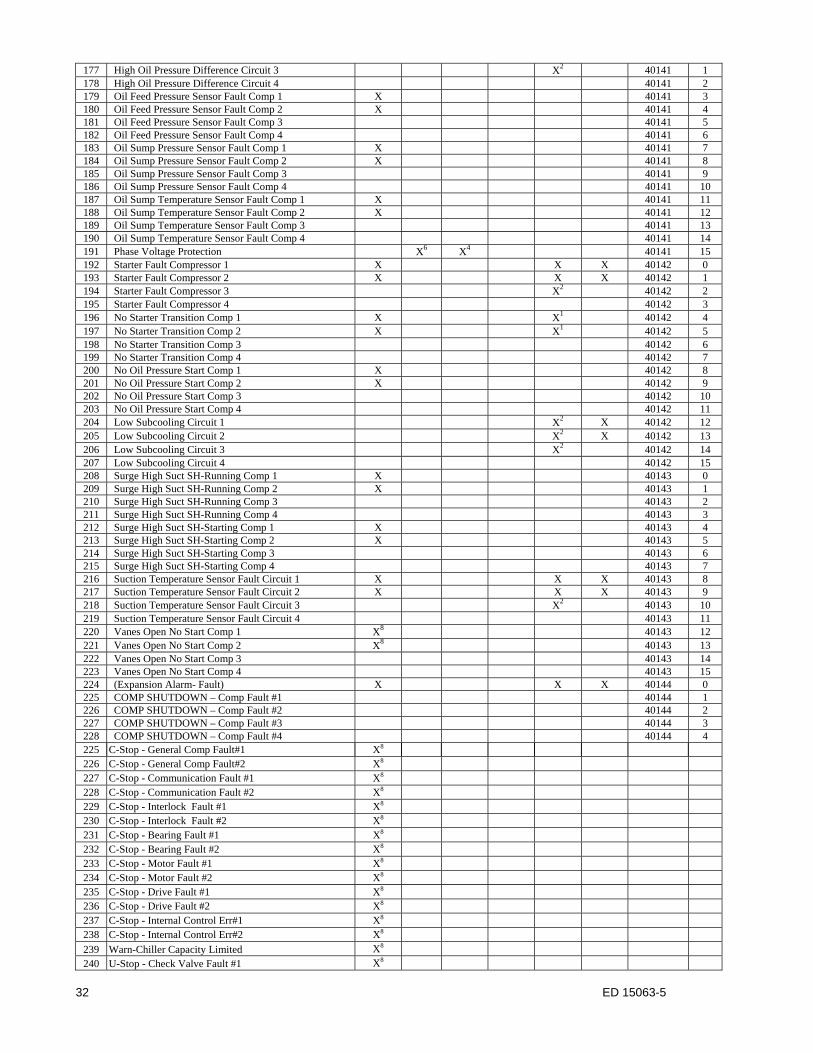
32 ED 15063-5
177 High Oil Pressure Difference Circuit 3 X2 40141 1 178 High Oil Pressure Difference Circuit 4 40141 2 179 Oil Feed Pressure Sensor Fault Comp 1 X 40141 3 180 Oil Feed Pressure Sensor Fault Comp 2 X 40141 4 181 Oil Feed Pressure Sensor Fault Comp 3 40141 5 182 Oil Feed Pressure Sensor Fault Comp 4 40141 6 183 Oil Sump Pressure Sensor Fault Comp 1 X 40141 7 184 Oil Sump Pressure Sensor Fault Comp 2 X 40141 8 185 Oil Sump Pressure Sensor Fault Comp 3 40141 9 186 Oil Sump Pressure Sensor Fault Comp 4 40141 10 187 Oil Sump Temperature Sensor Fault Comp 1 X 40141 11 188 Oil Sump Temperature Sensor Fault Comp 2 X 40141 12 189 Oil Sump Temperature Sensor Fault Comp 3 40141 13 190 Oil Sump Temperature Sensor Fault Comp 4 40141 14 191 Phase Voltage Protection X6 X4 40141 15 192 Starter Fault Compressor 1 X X X 40142 0 193 Starter Fault Compressor 2 X X X 40142 1 194 Starter Fault Compressor 3 X2 40142 2 195 Starter Fault Compressor 4 40142 3 196 No Starter Transition Comp 1 X X1 40142 4 197 No Starter Transition Comp 2 X X1 40142 5 198 No Starter Transition Comp 3 40142 6 199 No Starter Transition Comp 4 40142 7 200 No Oil Pressure Start Comp 1 X 40142 8 201 No Oil Pressure Start Comp 2 X 40142 9 202 No Oil Pressure Start Comp 3 40142 10 203 No Oil Pressure Start Comp 4 40142 11 204 Low Subcooling Circuit 1 X2 X 40142 12 205 Low Subcooling Circuit 2 X2 X 40142 13 206 Low Subcooling Circuit 3 X2 40142 14 207 Low Subcooling Circuit 4 40142 15 208 Surge High Suct SH-Running Comp 1 X 40143 0 209 Surge High Suct SH-Running Comp 2 X 40143 1 210 Surge High Suct SH-Running Comp 3 40143 2 211 Surge High Suct SH-Running Comp 4 40143 3 212 Surge High Suct SH-Starting Comp 1 X 40143 4 213 Surge High Suct SH-Starting Comp 2 X 40143 5 214 Surge High Suct SH-Starting Comp 3 40143 6 215 Surge High Suct SH-Starting Comp 4 40143 7 216 Suction Temperature Sensor Fault Circuit 1 X X X 40143 8 217 Suction Temperature Sensor Fault Circuit 2 X X X 40143 9 218 Suction Temperature Sensor Fault Circuit 3 X2 40143 10 219 Suction Temperature Sensor Fault Circuit 4 40143 11 220 Vanes Open No Start Comp 1 X8 40143 12 221 Vanes Open No Start Comp 2 X8 40143 13 222 Vanes Open No Start Comp 3 40143 14 223 Vanes Open No Start Comp 4 40143 15 224 (Expansion Alarm- Fault) X X X 40144 0 225 COMP SHUTDOWN – Comp Fault #1 40144 1 226 COMP SHUTDOWN – Comp Fault #2 40144 2 227 COMP SHUTDOWN – Comp Fault #3 40144 3 228 COMP SHUTDOWN – Comp Fault #4 40144 4 225 C-Stop - General Comp Fault#1 X8 226 C-Stop - General Comp Fault#2 X8 227 C-Stop - Communication Fault #1 X8 228 C-Stop - Communication Fault #2 X8 229 C-Stop - Interlock Fault #1 X8 230 C-Stop - Interlock Fault #2 X8 231 C-Stop - Bearing Fault #1 X8 232 C-Stop - Bearing Fault #2 X8 233 C-Stop - Motor Fault #1 X8 234 C-Stop - Motor Fault #2 X8 235 C-Stop - Drive Fault #1 X8 236 C-Stop - Drive Fault #2 X8 237 C-Stop - Internal Control Err#1 X8 238 C-Stop - Internal Control Err#2 X8 239 Warn-Chiller Capacity Limited X8 240 U-Stop - Check Valve Fault #1 X8
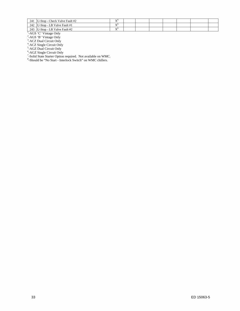
33 ED 15063-5
241 U-Stop - Check Valve Fault #2 X8 242 U-Stop - LB Valve Fault #1 X8 243 U-Stop - LB Valve Fault #2 X8
1-AGS ‘C’ Vintage Only 2-AGS ‘B’ Vintage Only 3-ACZ Dual Circuit Only 4-ACZ Single Circuit Only 5-AGZ Dual Circuit Only 6-AGZ Single Circuit Only 7-Solid State Starter Option required. Not available on WMC. 8-Should be “No Start - Interlock Switch” on WMC chillers.
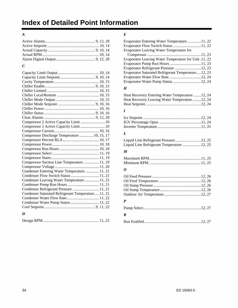
34 ED 15063-5
Index of Detailed Point Information
A
Active Alarms ................................................... 9, 12, 29 Active Setpoint ..................................................... 10, 14 Actual Capacity ................................................ 9, 10, 14 Actual RPM .......................................................... 10, 14 Alarm Digital Output ........................................ 9, 12, 28
C
Capacity Limit Output .......................................... 10, 14 Capacity Limit Setpoint .................................... 9, 10, 14 Cavity Temperature .............................................. 10, 15 Chiller Enable ................................................... 9, 10, 15 Chiller Limited ..................................................... 10, 15 Chiller Local/Remote ........................................... 10, 15 Chiller Mode Output ............................................. 10, 15 Chiller Mode Setpoint ...................................... 9, 10, 16 Chiller Power ........................................................ 10, 16 Chiller Status .................................................... 9, 10, 16 Clear Alarms ..................................................... 9, 12, 28 Compressor 2 Active Capacity Limit ......................... 16 Compressor 2 Active Capacity Limit ......................... 10 Compressor Current .............................................. 10, 16 Compressor Discharge Temperature .............. 10, 15, 17 Compressor Percent RLA ..................................... 10, 17 Compressor Power ................................................ 10, 18 Compressor Run Hours ........................................ 10, 18 Compressor Select ................................................ 11, 19 Compressor Starts ................................................. 11, 19 Compressor Suction Line Temperature ................ 11, 19 Compressor Voltage ............................................. 11, 20 Condenser Entering Water Temperature .............. 11, 21 Condenser Flow Switch Status ............................. 11, 21 Condenser Leaving Water Temperature ............... 11, 21 Condenser Pump Run Hours ................................ 11, 21 Condenser Refrigerant Pressure ........................... 11, 21 Condenser Saturated Refrigerant Temperature ..... 11, 21 Condenser Water Flow Rate ................................. 11, 22 Condenser Water Pump Status ............................. 11, 22 Cool Setpoint .................................................... 9, 11, 22
D
Design RPM ......................................................... 11, 22
E
Evaporator Entering Water Temperature ..............11, 22 Evaporator Flow Switch Status .............................11, 22 Evaporator Leaving Water Temperature for
Compressor .......................................................11, 23 Evaporator Leaving Water Temperature for Unit .11, 22 Evaporator Pump Run Hours ................................11, 23 Evaporator Refrigerant Pressure ...........................12, 23 Evaporator Saturated Refrigerant Temperature .....12, 23 Evaporator Water Flow Rate .................................12, 24 Evaporator Water Pump Status .............................12, 24
H
Heat Recovery Entering Water Temperature ........12, 24 Heat Recovery Leaving Water Temperature .........12, 24 Heat Setpoint .........................................................12, 24
I
Ice Setpoint ...........................................................12, 24 IGV Percentage Open ...........................................11, 24 Inverter Temperature .............................................11, 25
L
Liquid Line Refrigerant Pressure ..........................12, 25 Liquid Line Refrigerant Temperature ...................12, 25
M
Maximum RPM .....................................................11, 25 Minimum RPM .....................................................11, 25
O
Oil Feed Pressure ..................................................12, 26 Oil Feed Temperature ...........................................12, 26 Oil Sump Pressure .................................................12, 26 Oil Sump Temperature ..........................................12, 26 Outdoor Air Temperature ......................................12, 27
P
Pump Select ...........................................................12, 27
R
Run Enabled ..........................................................12, 27
35 ED 15063-5
Daikin McQuay (800) 432-1342, www.DaikinMcQuay.com
This document contains the most current product information as of this printing. For the most up-to-date product information, please go to www.DaikinMcQuay.com.