Embed Size (px)
Citation preview
Installation and Maintenance Manual IM 1012
Group: Controls Part Number: IM 1012 Date: April 2014 Supersedes: New
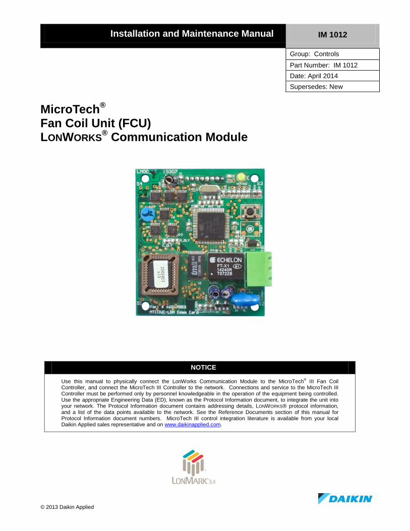
MicroTech® Fan Coil Unit (FCU) LONWORKS® Communication Module
NOTICE
Use this manual to physically connect the LonWorks Communication Module to the MicroTech® III Fan Coil Controller, and connect the MicroTech III Controller to the network. Connections and service to the MicroTech III Controller must be performed only by personnel knowledgeable in the operation of the equipment being controlled. Use the appropriate Engineering Data (ED), known as the Protocol Information document, to integrate the unit into your network. The Protocol Information document contains addressing details, LONWORKS® protocol information, and a list of the data points available to the network. See the Reference Documents section of this manual for Protocol Information document numbers. MicroTech III control integration literature is available from your local Daikin Applied sales representative and on www.daikinapplied.com.
© 2013 Daikin Applied
Contents REVISION HISTORY ............................................................................................................................ 3 TRADEMARK NOTICES ....................................................................................................................... 3
GENERAL INFORMATION ............................................................................................................ 4 HAZARD IDENTIFICATION MESSAGES ................................................................................................ 4 DESCRIPTION ..................................................................................................................................... 5 APPLICATION ..................................................................................................................................... 5 COMPONENT DATA ............................................................................................................................ 5
Service Pin .................................................................................................................................... 5 Service Light Emitting Diode (LED) ............................................................................................. 6 LONWORKS Network Connector (TB1) ........................................................................................ 6 8-Pin Header ................................................................................................................................. 7 LonMark Profile Software............................................................................................................. 7 Neuron ID ..................................................................................................................................... 7 Transceiver ................................................................................................................................... 7 Specifications ................................................................................................................................ 7
INSTALLATION ................................................................................................................................ 8 TOOLS REQUIRED .............................................................................................................................. 8 INSTALLING A LONWORKS COMMUNICATION MODULE .................................................................... 8 REPLACING A LONWORKS COMMUNICATION MODULE .................................................................... 9
NETWORK INTEGRATION .......................................................................................................... 11 CONNECTING UNIT TO THE NETWORK ............................................................................................. 11
Network Topology ....................................................................................................................... 11 Physical Network ........................................................................................................................ 13
ADDRESSING AND ESTABLISHING COMMUNICATION ....................................................................... 14 LONWORKS Network Addressing ................................................................................................. 14
COMMISSIONING THE NETWORK ...................................................................................................... 14 Configuration .............................................................................................................................. 14 External Interface File (XIF) and NXE Files .............................................................................. 14 Resource Files ............................................................................................................................. 15 The Network “Wink” Command ................................................................................................. 15
SERVICE INFORMATION ............................................................................................................ 16 TEST PROCEDURES .......................................................................................................................... 16 WARRANTY ..................................................................................................................................... 16 AFTERMARKET SERVICES ................................................................................................................ 16
Figures Figure 1. LONWORKS Communication Module Major Components .................................................... 6 Figure 2. Mounting a LONWORKS Communication Module to the FCU Unit Controller .................. 10 Figure 3. Singly Terminated Free Topology Networks ...................................................................... 12 Figure 4. Combining Network Segments With a Repeater ................................................................. 12
2 IM 1012

Revision History IM 1012 April 2014 Initial release
Reference Documents Number Company Title Source
078-0014-01E LonMark® Interoperability Association
LonMark® Layers 1-6 Interoperability Guidelines, Version 3.0
www.lonmark.org
078-0120-01E LonMark Interoperability Association
LonMark Application Layer Interoperability Guidelines, Version 3.2
www.lonmark.org
078-0156-01G Echelon® Corporation LonWorks® FTT-10A Free Topology Transceiver Users Guide
www.echelon.com
8503_ LonMark Interoperability Association
Space Comfort Control (SCC) -Fan Coil Functional Profile
www.lonmark.org
ED 15135 Daikin Applied Protocol Information for MicroTech III Fan Coil Unit Controller, LonWorks and BACnet MS/TP
www.daikinapplied.com
OM 1111 Daikin Applied MicroTech III Fan Coil Unit Controller Operation and Maintenance Manual
www.daikinapplied.com
Trademark Notices Copyright © 2013 Daikin Applied, Minneapolis MN. All rights reserved throughout the world. Daikin Applied reserves the right to change any information contained herein without prior notice. The user is responsible for determining whether this software is appropriate for his or her application. The following are trademarks or registered trademarks of their respective companies. Windows from Microsoft Corporation; BACnet from ASHRAE; LONWORKS, LONMARK, LonTalk, and Neuron from Echelon Corporation; MicroTech III, and Applied Terminal Systems from Daikin Applied. LONMARK and the LONMARK logo are managed, granted, and used by LONMARK International under a license granted by Echelon Corporation.
IM 1012 3
General Information
This manual contains the information you need to install the LONWORKS Communication Module to a MicroTech III Fan Coil (FCU) Unit Controller and integrate it into the network.
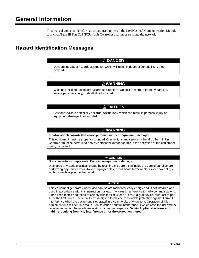
Hazard Identification Messages
! DANGER
Dangers indicate a hazardous situation which will result in death or serious injury if not avoided.
! WARNING
Warnings indicate potentially hazardous situations, which can result in property damage, severe personal injury, or death if not avoided.
! CAUTION
Cautions indicate potentially hazardous situations, which can result in personal injury or equipment damage if not avoided.
! WARNING Electric shock hazard. Can cause personal injury or equipment damage. This equipment must be properly grounded. Connections and service to the MicroTech III Unit Controller must be performed only by personnel knowledgeable in the operation of the equipment being controlled.
! CAUTION Static sensitive components. Can cause equipment damage. Discharge any static electrical charge by touching the bare metal inside the control panel before performing any service work. Never unplug cables, circuit board terminal blocks, or power plugs while power is applied to the panel.
NOTICE This equipment generates, uses, and can radiate radio frequency energy and, if not installed and used in accordance with this instruction manual, may cause interference to radio communications. It has been tested and found to comply with the limits for a Class A digital device, pursuant to part 15 of the FCC rules. These limits are designed to provide reasonable protection against harmful interference when the equipment is operated in a commercial environment. Operation of this equipment in a residential area is likely to cause harmful interference in which case the user will be required to correct the interference at his or her own expense. Daikin Applied disclaims any liability resulting from any interference or for the correction thereof.
4 IM 1012
Description A LONWORKS Communication Module provides the interface between the MicroTech III Fan Coil Unit (FCU) Controller and a LONWORKS Local Operating Network (LON). It translates the LonTalk® variables used on the network to the variables used in the unit controller and vice versa. It translates in accordance with the LONMARK Functional Profile. Profiles are interpreted in loaded programs (firmware). The LONWORKS communication module is a printed circuit board that connects onto the top side of the MicroTech III FCU unit controller (i.e. baseboard.) See Figure 1 for details.
Application A LONWORKS communication module connects the MicroTech III FCU unit controller to the building automation system (BAS) on a LONWORKS network. It is the interface adapter for the exchange of LonTalk variables between the network and the unit controller. The LONWORKS communication module translates the LonTalk variables to the unit controller. Refer to the MicroTech III FCU Unit Controller Operation Manual, OM 1111, available on www.daikinapplied.com, for details.
Component Data The following section describes the important features of the LONWORKS communication module for network commissioning, operation, and troubleshooting. Figure 1 shows the location of these major components on the communication module.
Service Pin The service pin button generates a service-switch message, which contains the Neuron® ID and the program code identification of the device, or node. A service-switch message is a network message that is generated by a node and broadcast on the network. It is used to commission the device on the LONWORKS network. The service pin is activated by pressing down on the small round black button on top of the service switch. See Figure 1 for the location of the service pin button.
IM 1012 5
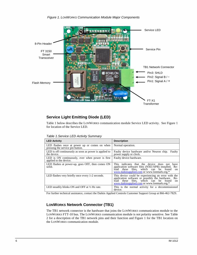
Figure 1. LONWORKS Communication Module Major Components
Service Light Emitting Diode (LED) Table 1 below describes the LONWORKS communication module Service LED activity. See Figure 1 for location of the Service LED.
Table 1.Service LED Activity Summary LED Activity Description LED flashes once at power up or comes on when pressing the service pin button.
Normal operation.
LED is off continuously as soon as power is applied to the device.
Faulty device hardware and/or Neuron chip. Faulty power supply or clock.
LED is ON continuously, ever when power is first applied to the device.
Faulty device hardware.
LED flashes at power-up, goes OFF, then comes ON solid.
This indicates that the device does not have application software files (NXE/APB) installed. Re-load these files, which can be found on www.daikinapplied.com or www.lonmark.org.*
LED flashes very briefly once every 1-2 seconds. This device could be experiencing an error with the application software or possibly the hardware. Re-load these files, which can be found on www.daikinapplied.com or www.lonmark.org.*
LED steadily blinks ON and OFF at ½ Hz rate. This is the normal activity for a decommissioned device.
For further technical assistance, contact the Daikin Applied Controls Customer Support Group at 866-462-7829.
LONWORKS Network Connector (TB1) The TB1 network connector is the hardware that joins the LONWORKS communication module to the LONWORKS FTT-10 bus. The LONWORKS communication module is not polarity sensitive. See Table 2 for a description of the TB1 network pins and their function and Figure 1 for the TB1 location on the LONWORKS communication module.
Service LED
Service Pin
TB1 Network Connector
8-Pin Header
FT-X1 Transformer
FT 3150 Smart
Transceiver
Flash Memory
Pin3: SHLD Pin2: Signal B / - Pin1: Signal A / +
6 IM 1012
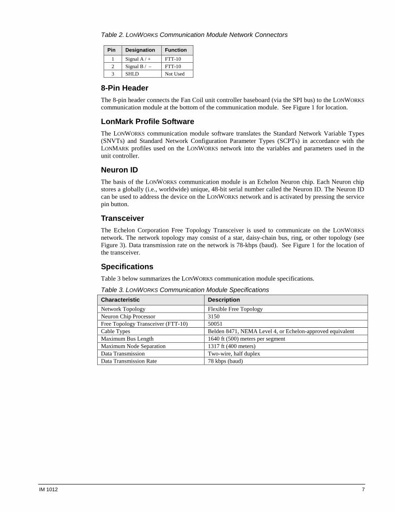
Table 2. LONWORKS Communication Module Network Connectors
Pin Designation Function 1 Signal A / + FTT-10 2 Signal B / – FTT-10 3 SHLD Not Used
8-Pin Header The 8-pin header connects the Fan Coil unit controller baseboard (via the SPI bus) to the LONWORKS communication module at the bottom of the communication module. See Figure 1 for location.
LonMark Profile Software The LONWORKS communication module software translates the Standard Network Variable Types (SNVTs) and Standard Network Configuration Parameter Types (SCPTs) in accordance with the LONMARK profiles used on the LONWORKS network into the variables and parameters used in the unit controller.
Neuron ID The basis of the LONWORKS communication module is an Echelon Neuron chip. Each Neuron chip stores a globally (i.e., worldwide) unique, 48-bit serial number called the Neuron ID. The Neuron ID can be used to address the device on the LONWORKS network and is activated by pressing the service pin button.
Transceiver The Echelon Corporation Free Topology Transceiver is used to communicate on the LONWORKS network. The network topology may consist of a star, daisy-chain bus, ring, or other topology (see Figure 3). Data transmission rate on the network is 78-kbps (baud). See Figure 1 for the location of the transceiver.
Specifications Table 3 below summarizes the LONWORKS communication module specifications.
Table 3. LONWORKS Communication Module Specifications Characteristic Description Network Topology Flexible Free Topology Neuron Chip Processor 3150 Free Topology Transceiver (FTT-10) 50051 Cable Types Belden 8471, NEMA Level 4, or Echelon-approved equivalent Maximum Bus Length 1640 ft (500) meters per segment Maximum Node Separation 1317 ft (400 meters) Data Transmission Two-wire, half duplex Data Transmission Rate 78 kbps (baud)
IM 1012 7
Installation
The LONWORKS communication module can be installed in the field or in the factory. See the Aftermarket Services section for replacement part ordering information. The LONWORKS communication module mounts on the MicroTech III FCU unit controller with connector pins and is held in place with four plastic, edge-holding circuit board supports. Field wiring connections to the LONWORKS network are made at the three-terminal plug (TB1) on the LONWORKS communication module (see Figure 1).
Tools Required The following is the list of items is required for field installation of a new communication module or replacement of an existing communication module.
• The LONWORKS Communication Module • Four plastic standoffs • Flat-head screwdriver • Network connector (attached to the communication module) • IM 1005 • Twisted pair network cable
Installing a LONWORKS Communication Module Follow these procedures to install a new LONWORKS communication module on a MicroTech III FCU unit controller so that the unit can then be incorporated into a LONWORKS network.
! DANGER
The terminals on the Fan Coil unit controller are high voltage. Disconnect power to avoid electrical shock potential, which will result in death or serious injury if not avoided.
1. Disconnect power from the MicroTech III FCU unit controller (i.e. baseboard). 2. Unplug the unwired female network-cable connector from the board-mounted male plug, TB1. 3. Install the four standoffs on the baseboard (see Figure 2). 4. Locate the 8-pin header male connector on the baseboard. Orient the LONWORKS communication
module so that the component side faces away from the baseboard and the connector pins can mate with the connector on the bottom of the LONWORKS communication module. Press the LONWORKS communication module on to the baseboard connector pins and standoffs until you hear the faint click of the locking standoffs securing the module in place (see Figure 1).
5. Connect the LONWORKS network cable to the female network-cable connector using a flat-head screwdriver. Then reinsert the plug into TB1 on the LONWORKS communication module (see Figure 4).
6. Reapply power to the MicroTech III FCU baseboard.
Note: The LONWORKS communication module software version requires compatibility with the FCU unit controller software version. Refer to the MicroTech III FCU Unit Controller Operation and Maintenance manual, available on www.daikinapplied.com, for details.
8 IM 1012
Replacing a LONWORKS Communication Module Follow these procedures to remove an existing LONWORKS communication module, replace it, and incorporate it into an existing LONWORKS network.
! DANGER
The terminals on the unit controller are high voltage. Disconnect power to avoid electrical shock potential, which will result in death or serious injury if not avoided.
1. Disconnect power from the MicroTech III FCU baseboard. 2. Unplug the wired female network-cable connector from the board-mounted male plug, TB1. 3. Locate the standoffs used to connect the LONWORKS communication module to the baseboard. 4. Use a finger or screwdriver to depress the barb on one standoff and gently pull the corner of the
board over the tab. Take care not to bend the module or misalign the connector pins. 5. Proceed to the other three corners and pull the board over the standoffs. 6. Gently lift the LONWORKS communication module from the baseboard. 7. Locate the blank connector and four standoffs for the LONWORKS communication module on the
baseboard (see Figure 2). 8. Orient the LONWORKS communication module’s printed circuit board so that the component side
faces away from the baseboard and the 8-pin header connector pins can mate with the connector on the LONWORKS communication module.
9. Press the module onto the connector pins and standoffs until you hear the faint click of the locking standoffs securing the LONWORKS communication module in place.
10. Reinsert the plug into TB1 on the LONWORKS communication module (see Figure 1).
IM 1012 9
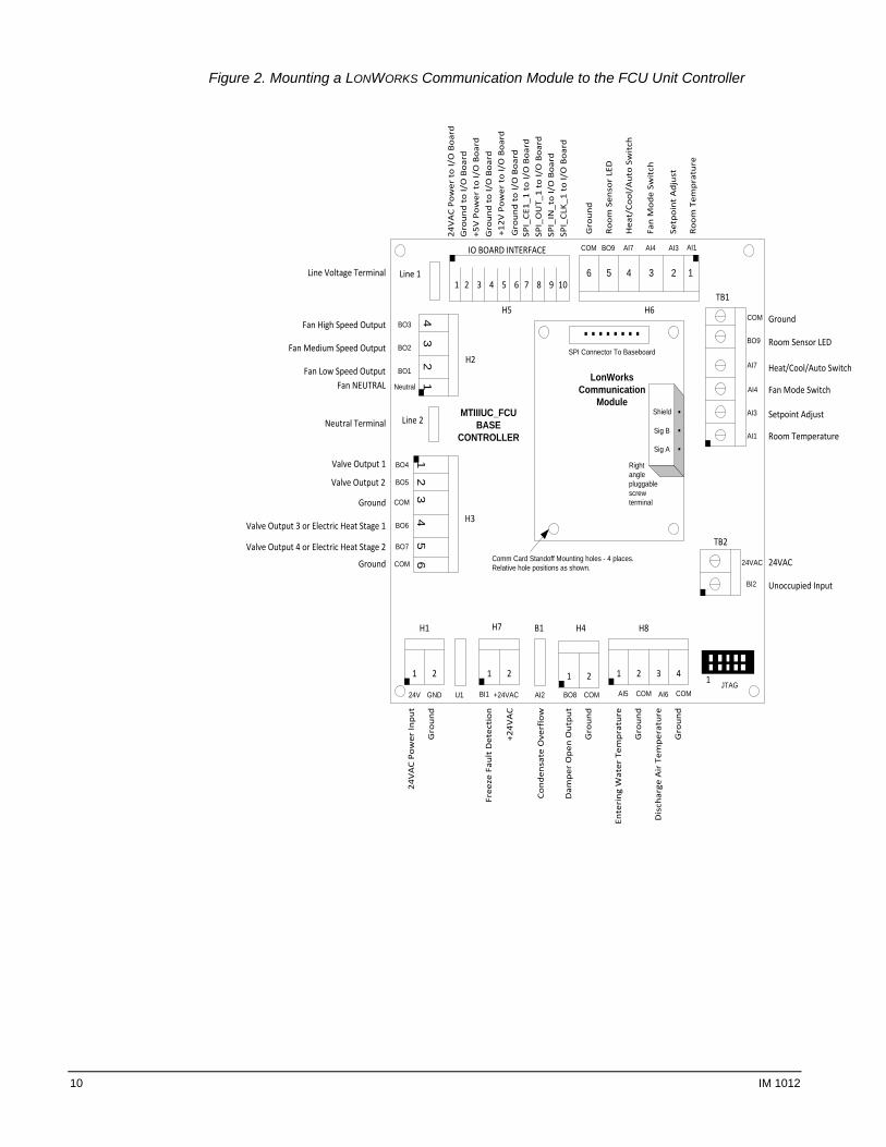
Figure 2. Mounting a LONWORKS Communication Module to the FCU Unit Controller
12
34
56
43
21
1 2 1 2 1 2 1 2 3 4
H1
U1
H7 B1 H4 H8
JTAG
Line 2
H3
H2
Line 1
H5 H6TB1
TB2
24V
AC
Pow
er In
put
Gro
und
24VAC
Unoccupied Input
Ground
Room Sensor LED
Heat/Cool/Auto Switch
Fan Mode Switch
Setpoint Adjust
Room Temperature
123456
Room
Tem
prat
ure
Setp
oint
Adj
ust
Fan
Mod
e Sw
itch
Hea
t/Co
ol/A
uto
Swit
ch
Room
Sen
sor
LED
Gro
und
Ente
ring
Wat
er T
empr
atur
e
Gro
und
Dis
char
ge A
ir T
empe
ratu
re
Gro
und
Dam
per
Ope
n O
utpu
t
Gro
und
Cond
ensa
te O
verf
low
Free
ze F
ault
Det
ecti
on
+24V
AC
Ground
Valve Output 1
Valve Output 2
Ground
Valve Output 3 or Electric Heat Stage 1
Valve Output 4 or Electric Heat Stage 2
Fan High Speed Output
Fan Medium Speed Output
Fan Low Speed OutputFan NEUTRAL
1 10
IO BOARD INTERFACE
24V
AC
Pow
er t
o I/
O B
oard
Gro
und
to I/
O B
oard
+5V
Pow
er t
o I/
O B
oard
Gro
und
to I/
O B
oard
+12V
Pow
er t
o I/
O B
oard
Gro
und
to I/
O B
oard
SPI_
CE1_
1 to
I/O
Boa
rdSP
I_O
UT_
1 to
I/O
Boa
rdSP
I_IN
_to
I/O
Boa
rdSP
I_CL
K_1
to I/
O B
oard
Neutral Terminal
Line Voltage Terminal. .
. .
.. . . .
24V GND BI1 +24VAC AI2 BO8 COM AI5 COM AI6 COM
COM
BO9
AI7
AI4
AI3
AI1
24VAC
BI2
BO3
BO2
BO1
Neutral
BO4
BO5
COM
BO6
BO7
COM
COM BO9 AI7 AI4 AI3 AI1
.........
SPI Connector To Baseboard
.
.
.
MTIIIUC_FCUBASE
CONTROLLER
Comm Card Standoff Mounting holes - 4 places.Relative hole positions as shown.
1
2 3 4 5 6 7 8 9
LonWorksCommunication
ModuleShield
Rightanglepluggablescrewterminal
Sig B
Sig A
10 IM 1012
Network Integration
Integrating the LONWORKS communication module into a BAS involves three steps: • Connecting the unit (node) to the network • Addressing and establishing communications with the unit • Configuring the unit to the building
Connecting Unit to the Network After the LONWORKS communication module has been properly installed on the FCU unit controller, it can then be physically connected into the third party LONWORKS network. Figure 2 shows the LONWORKS communication module connected to the FCU unit controller. Connect the network connector (TB1) pins 2 and 3, located on the communication module, to the LONWORKS network (see Figure 1).
Network Topology Each LONWORKS communication module is equipped with an FT-X1 transceiver for network communications. This transceiver allows for (1) free topology network wiring schemes using twisted pair (unshielded) cable and (2) polarity insensitive connections at each node. These features greatly simplify installation and reduce potential network commissioning issues. Additional nodes may be added with little regard to the existing cable routing.
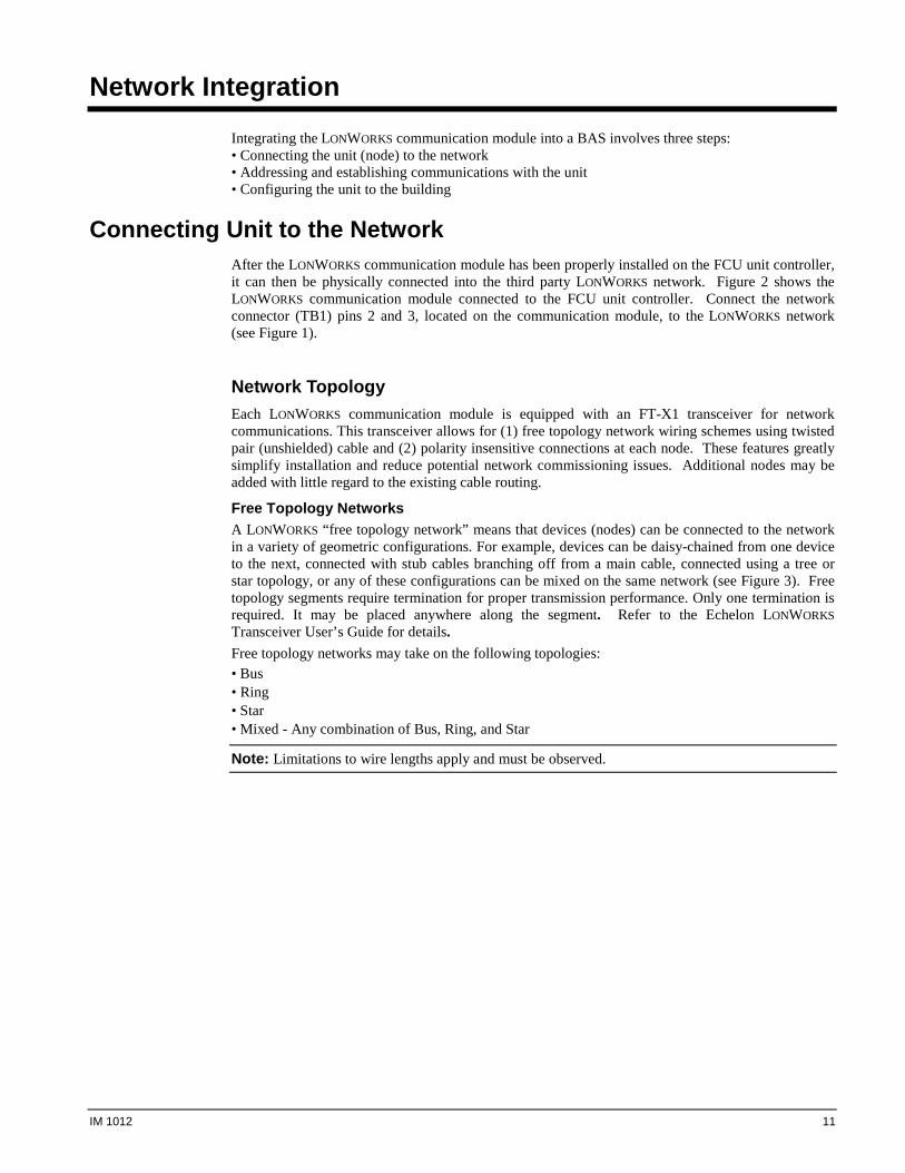
Free Topology Networks A LONWORKS “free topology network” means that devices (nodes) can be connected to the network in a variety of geometric configurations. For example, devices can be daisy-chained from one device to the next, connected with stub cables branching off from a main cable, connected using a tree or star topology, or any of these configurations can be mixed on the same network (see Figure 3). Free topology segments require termination for proper transmission performance. Only one termination is required. It may be placed anywhere along the segment. Refer to the Echelon LONWORKS Transceiver User’s Guide for details. Free topology networks may take on the following topologies: • Bus • Ring • Star • Mixed - Any combination of Bus, Ring, and Star
Note: Limitations to wire lengths apply and must be observed.
IM 1012 11
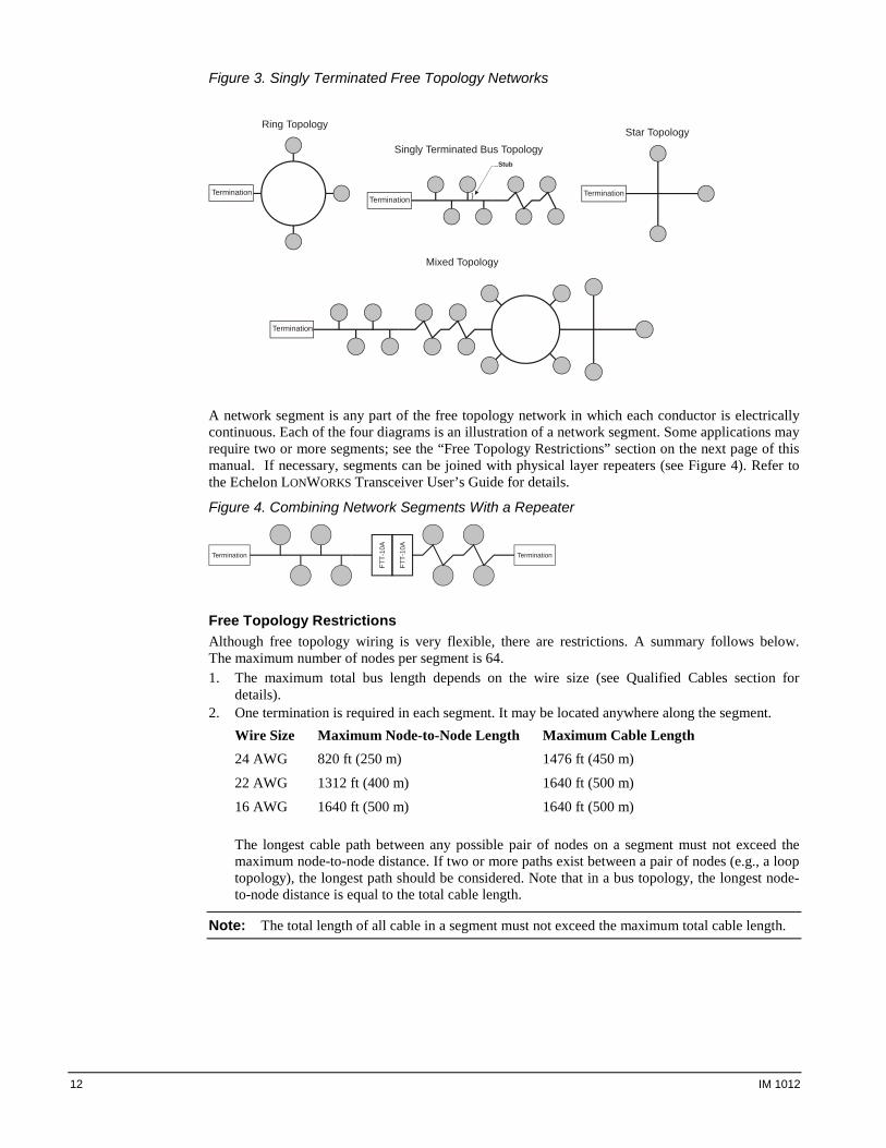
Figure 3. Singly Terminated Free Topology Networks
Termination
Star Topology
Termination
Ring Topology
Termination
Singly Terminated Bus TopologyStub
}
Termination
Mixed Topology
A network segment is any part of the free topology network in which each conductor is electrically continuous. Each of the four diagrams is an illustration of a network segment. Some applications may require two or more segments; see the “Free Topology Restrictions” section on the next page of this manual. If necessary, segments can be joined with physical layer repeaters (see Figure 4). Refer to the Echelon LONWORKS Transceiver User’s Guide for details.
Figure 4. Combining Network Segments With a Repeater
Termination Termination
FTT-
10A
FTT-
10A
Free Topology Restrictions Although free topology wiring is very flexible, there are restrictions. A summary follows below. The maximum number of nodes per segment is 64. 1. The maximum total bus length depends on the wire size (see Qualified Cables section for
details). 2. One termination is required in each segment. It may be located anywhere along the segment.
Wire Size Maximum Node-to-Node Length Maximum Cable Length 24 AWG 820 ft (250 m) 1476 ft (450 m)
22 AWG 1312 ft (400 m) 1640 ft (500 m)
16 AWG 1640 ft (500 m) 1640 ft (500 m)
The longest cable path between any possible pair of nodes on a segment must not exceed the maximum node-to-node distance. If two or more paths exist between a pair of nodes (e.g., a loop topology), the longest path should be considered. Note that in a bus topology, the longest node-to-node distance is equal to the total cable length.
Note: The total length of all cable in a segment must not exceed the maximum total cable length.
12 IM 1012
Physical Network Qualified Cables Echelon has qualified three twisted-pair network communications cables that are available from a large number of different sources. Refer to the Echelon LONWORKS Free Topology Transceiver Users Guide for cable specification details. Some local codes or applications may require the use of plenum-rated cable. The following cables meet this specification:
1. TIA568A Category 5 cable (24AWG/0.51mm) 2. NEMA Level IV cable (22AWG/0.65mm) 3. Generic 16AWG (1.3mm) (similar to Belden 85102)
! CAUTION
Do not install the cable in the same conduit with power wiring. The temperature of the cable must not exceed 131 ºF (55 ºC), which can result in personal injury or equipment damage if not avoided.
Note: Ideally, you should connect two unit controllers with one continuous piece of cable in order to reduce the risk of communications errors. If you must splice the cable, use crimp-type butt connectors (good) or solder (best). Do not use wire nuts.
Network Cable Termination LONWORKS network segments require termination for proper data transmission performance. The type and number of terminations depend on network topology. Refer to the Echelon LONWORKS Transceiver User’s Guide for details.
IM 1012 13
Addressing and Establishing Communication LONWORKS Network Addressing Every Neuron Chip has a unique 48-bit Neuron ID or physical address. This address is generally used only at initial installation or for diagnostic purposes. For normal network operation, a device address is used. Device addresses are defined at the time of network configuration. All device addresses have three parts. The first part is the Domain ID, designating the domain. Devices must be in the same domain in order to communicate with each other. The second part is the Subnet ID that specifies a collection of up to 127 devices that are on a single channel or a set of channels connected by repeaters. There may be up to 255 subnets in a domain. The third part is the Node ID that identifies an individual device within the subnet. A group is a logical collection of devices within a domain. Groups are assembled with regard for their physical location in the domain. There may be up to 256 groups in a domain. A group address is the address that identifies all devices of the group. There may be any number of devices in a group when unacknowledged messaging is used. Groups are limited to 64 devices if acknowledged messaging is used. A broadcast address identifies all devices within a subnet or domain.
Commissioning the Network Pressing the service pin generates a service-pin message, which contains the Neuron ID and the program code identification of the node. A service-pin message is a network message that is generated by a node and broadcast on the network. It can be used to commission the LONWORKS network. A network configuration tool maps device Neuron IDs to the domain/subnet/node logical addressing scheme when it creates the network image, the logical network addresses and connection information for all devices (nodes) on the network.
Configuration The LONWORKS communication module is LONMARK 3.4 certified and is configured in accordance with the LONMARK SCC - Fan Coil functional profile. The unit controller, along with the LONWORKS communication module, is ready to operate with the default parameter values in the unit controller. Refer to the protocol document, ED15135, available on www.daikinapplied.com, for details.
External Interface File (XIF) and NXE Files The LONWORKS Communication Module is self-documenting so that any LONWORKS network management tool can obtain all the information needed over the network to connect it into the system and to configure and manage it. An external interface file (a specially formatted PC text file with the extension .XIF) is required, along with LONWORKS network management tool, so that you can design and configure the device prior to installation. The NXE file contains the application image that is downloaded into the LONWORKS Communication Module. The LONWORKS Communication Module uses a separate NXE file specific to the Space Comfort Control (SCC) - Fan Coil functional profile. The XIF and NXE files are available at www.daikinapplied.com or www.lonmark.org. Refer to MicroTech III FCU Unit Controller Protocol Information, ED 15135 for additional details.
14 IM 1012
Resource Files Resource files contain definitions of functional profiles, network variables types, configuration property types, and enumerations. Resource files are used during the commissioning process and are required for displaying user-specific variables that are not included in the standard device profile. These files must be downloaded to the BAS front end workstation or other commissioning device. They are available at www.daikinapplied.com or www.lonmark.org. Refer to ED 15135 for additional details.
The Network “Wink” Command A wink command is initiated by the BAS or through the LONWORKS commissioning software. The “wink” identification function allows verification of an individual unit controller network address without having to physically open the unit’s access panels. The Wink command can be used during all operating and non-operating (ex. Alarm) modes except for the following conditions:
• Invalid Equipment Configuration Alarm • Emergency Shutdown Alarm • Actuator Calibration Process
Upon receiving a wink command from a network management node, the Unit Controller exhibits the following identification sequence (all occur simultaneously): • Room Sensor LED flashes (ON for 3.0 sec, OFF for 3.0 sec) for 15 total seconds, unless an
alarm condition exists. • Fan: The fan turns off for 5 seconds, turns on for 5 seconds, then off again for 5 seconds.
IM 1012 15
Service Information
Test Procedures If you can control the unit from the local room sensor, but you are unable to communicate with the unit via the network: • Check the network wiring. • Check addressing -- press the Service Switch on the communication module to send the service
message to the network. The service Switch message contains the Neuron ID and the program code identification of the node.
If the LONWORKS communication module still does not respond, contact the Controls Customer Support Group at 866-462-7829.
Warranty All Daikin Applied equipment is sold pursuant to its standard terms and conditions of sale, including Limited Product Warranty. Consult your local Daikin Applied Representative for warranty details. Refer to Form 933-430285Y. To find your local Daikin Applied Representative, go to www.daikinapplied.com.
Aftermarket Services To find your local parts office, visit www.daikinapplied.com or call 800-37PARTS (800-377-2787). To find your local service office, visit www.daikinapplied.com or call 800-432-1342.
This document contains the most current product information as of this printing. For the most current product information, please go to www.daikinapplied.com. All equipment is sold pursuant to Daikin Applied Standard Terms and Conditions of Sale and Limited Warranty.