Embed Size (px)
Citation preview
Application Note Fan Coil Unit
Issue Date October 9, 2009
© 2009 Johnson Controls, Inc. www.johnsoncontrols.com
Application Note - Fan Coil Unit (FCU) Controller
Application Note - Fan Coil Unit (FCU) Controller ................................4
Introduction............................................................................................................4
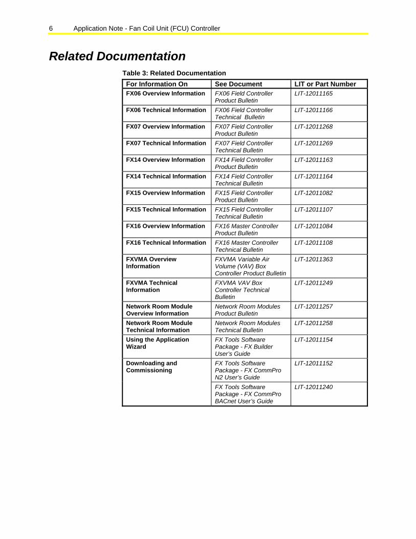
Related Documentation.........................................................................................6
Key Concepts.........................................................................................................7
State-based Control ............................................................................................................. 7
Occupancy Determination.................................................................................................... 8
Zone Temperature Control................................................................................................... 9
Effective Zone Temperature Setpoint Determination ........................................................... 9
Occupied Control Sequencer ............................................................................................. 10
Unoccupied Control Sequencer ......................................................................................... 12
Sequencers........................................................................................................................ 14 Emergency Heat .......................................................................................................... 14 No Airflow..................................................................................................................... 14 Unit Enable................................................................................................................... 15
Control of Staged Devices ................................................................................................. 16 Zone Control of Staged Devices .................................................................................. 16
Device Availability Determination....................................................................................... 16
Output Device Control........................................................................................................ 17 Heating......................................................................................................................... 17 Cooling ......................................................................................................................... 21 Two-Pipe Coil ............................................................................................................... 24 Supply Fan ................................................................................................................... 24
PID Tuning ......................................................................................................................... 27 Integral Time ................................................................................................................ 27 Proportional Band ........................................................................................................ 27 Saturation Time............................................................................................................ 27
FX Builder Application Wizard Concepts ..........................................................29
Installing the FCU Application Package ............................................................................. 29
Selecting the FCU Application Template ........................................................................... 32
Configuring the FCU Application........................................................................................ 33
Code No. LIT-12011305
2 Application Note - Fan Coil Unit (FCU) Controller
Configuring the Control Strategy.................................................................................. 33 Configuring the Network Room Module (NRM)............................................................ 35 Adjusting Setpoints ...................................................................................................... 37 Adjusting Parameters................................................................................................... 38 Adjusting Proportional plus Integral plus Derivative (PID) Parameters ........................ 39 Configuring the Internal Occupancy Schedule............................................................. 40 Viewing the Configuration Summary............................................................................ 41 Viewing Required Inputs and Outputs......................................................................... .41
Selecting the User Interface(s) and Supervisor Interface .................................................. 42
Selecting the Target Device ............................................................................................... 42
Configuring the Hardware I/Os........................................................................................... 43
Generating the Application Files and Documentation ........................................................ 46 Viewing Generated Application and Documentation Files ........................................... 47
Reviewing an Exported Application File............................................................................. 47
FX CommPro Concepts.......................................................................................49
User Interface Concepts......................................................................................49
Medium User Interface....................................................................................................... 50 Medium User Interface Capabilities ............................................................................. 50 Medium User Interface Navigation............................................................................... 51 Config Folder................................................................................................................ 52 NRM Setup Folder ....................................................................................................... 53 Status Folder................................................................................................................ 54 Setpoints Folder ........................................................................................................... 55 Parameters Folder ....................................................................................................... 55 PID Parameters Folder ................................................................................................ 56 Modes .......................................................................................................................... 56 Balancer Folder............................................................................................................ 59 Time Folder .................................................................................................................. 60 Schedulers Folder ........................................................................................................ 61 Password Folder .......................................................................................................... 61 MUI Status LEDs.......................................................................................................... 61 Accessing a Folder in the MUI ..................................................................................... 61 Changing a Configuration Setting, Setpoint, or Parameter in the MUI......................... 61
LCD2x4 User Interface....................................................................................................... 62 LCD2x4 User Interface Capabilities ............................................................................. 62 LCD2x4 User Interface Navigation............................................................................... 63 Config Page ................................................................................................................. 64 NRM Setup Page ......................................................................................................... 65 FX Setup Page............................................................................................................. 66 Setpoints Page............................................................................................................. 66 Parameters Page ......................................................................................................... 67 PID Parameters Page .................................................................................................. 68 Modes .......................................................................................................................... 68 Balancer Page.............................................................................................................. 70 Time Page.................................................................................................................... 71

Application Note - Fan Coil Unit (FCU) Controller 3
Schedulers Page.......................................................................................................... 72 Password Page ............................................................................................................ 72 Events Page................................................................................................................. 73 Graphical Status Icons ................................................................................................. 73 Accessing a Page in the LCD2x4 UI ............................................................................ 73 Changing a Configuration Setting, Setpoint, or Parameter in the LCD2x4 UI.............. 73
Supervisor Interface ............................................................................................74
4 Application Note - Fan Coil Unit (FCU) Controller
Application Note - Fan Coil Unit (FCU) Controller
Introduction This application note introduces the standard Fan Coil Unit (FCU) application template, provides procedures to configure the application using FX Builder’s Application Wizard, and explains how to commission the system using the Integral and Medium User Interface and FX CommPro.
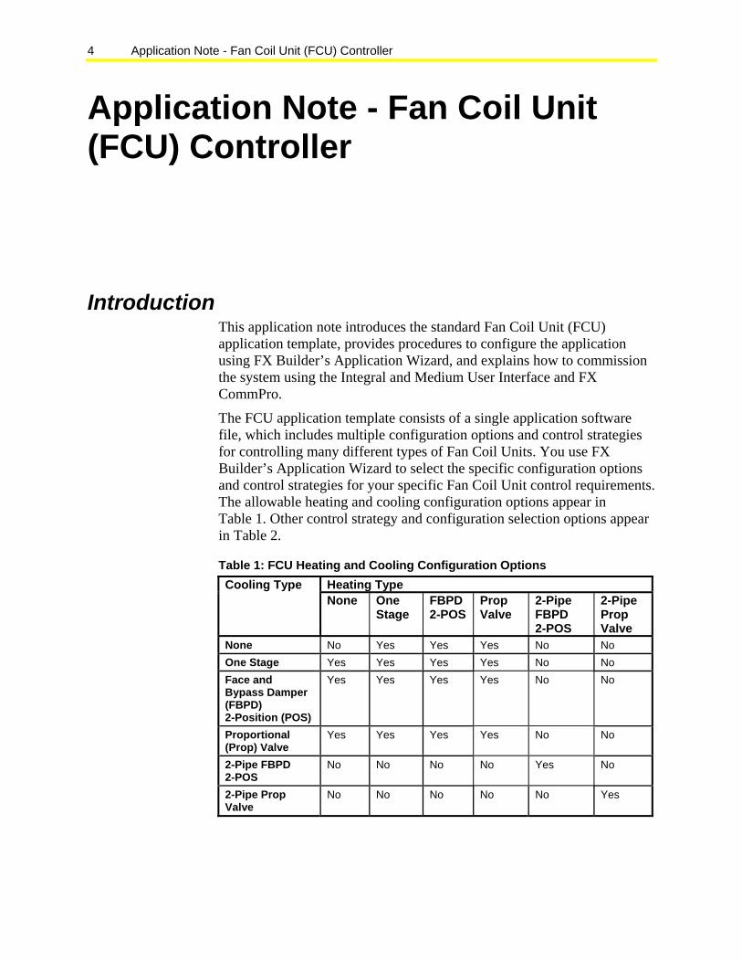
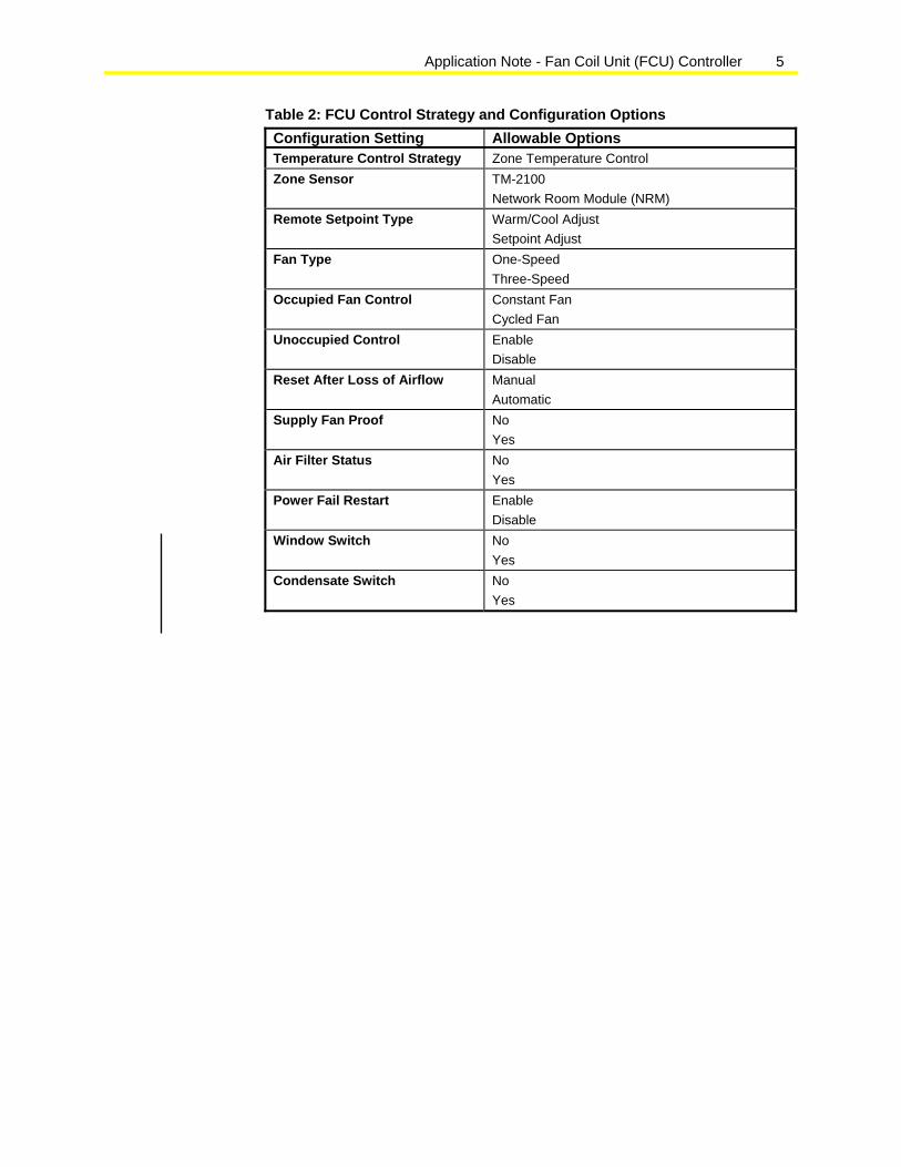
The FCU application template consists of a single application software file, which includes multiple configuration options and control strategies for controlling many different types of Fan Coil Units. You use FX Builder’s Application Wizard to select the specific configuration options and control strategies for your specific Fan Coil Unit control requirements. The allowable heating and cooling configuration options appear in Table 1. Other control strategy and configuration selection options appear in Table 2.
Table 1: FCU Heating and Cooling Configuration Options Heating Type Cooling Type None One
Stage FBPD 2-POS
Prop Valve
2-Pipe FBPD 2-POS
2-Pipe Prop Valve
None No Yes Yes Yes No No One Stage Yes Yes Yes Yes No No Face and Bypass Damper (FBPD) 2-Position (POS)
Yes Yes Yes Yes No No
Proportional (Prop) Valve
Yes Yes Yes Yes No No
2-Pipe FBPD 2-POS
No No No No Yes No
2-Pipe Prop Valve
No No No No No Yes
Application Note - Fan Coil Unit (FCU) Controller 5
Table 2: FCU Control Strategy and Configuration Options Configuration Setting Allowable Options Temperature Control Strategy Zone Temperature Control Zone Sensor TM-2100
Network Room Module (NRM) Remote Setpoint Type Warm/Cool Adjust
Setpoint Adjust Fan Type One-Speed
Three-Speed Occupied Fan Control Constant Fan
Cycled Fan Unoccupied Control Enable
Disable Reset After Loss of Airflow Manual
Automatic Supply Fan Proof No
Yes Air Filter Status No
Yes Power Fail Restart Enable
Disable Window Switch No
Yes Condensate Switch No
Yes
6 Application Note - Fan Coil Unit (FCU) Controller
Related Documentation Table 3: Related Documentation For Information On See Document LIT or Part Number FX06 Overview Information FX06 Field Controller
Product Bulletin LIT-12011165
FX06 Technical Information FX06 Field Controller Technical Bulletin
LIT-12011166
FX07 Overview Information FX07 Field Controller Product Bulletin
LIT-12011268
FX07 Technical Information FX07 Field Controller Technical Bulletin
LIT-12011269
FX14 Overview Information FX14 Field Controller Product Bulletin
LIT-12011163
FX14 Technical Information FX14 Field Controller Technical Bulletin
LIT-12011164
FX15 Overview Information FX15 Field Controller Product Bulletin
LIT-12011082
FX15 Technical Information FX15 Field Controller Technical Bulletin
LIT-12011107
FX16 Overview Information FX16 Master Controller Product Bulletin
LIT-12011084
FX16 Technical Information FX16 Master Controller Technical Bulletin
LIT-12011108
FXVMA Overview Information
FXVMA Variable Air Volume (VAV) Box Controller Product Bulletin
LIT-12011363
FXVMA Technical Information
FXVMA VAV Box Controller Technical Bulletin
LIT-12011249
Network Room Module Overview Information
Network Room Modules Product Bulletin
LIT-12011257
Network Room Module Technical Information
Network Room Modules Technical Bulletin
LIT-12011258
Using the Application Wizard
FX Tools Software Package - FX Builder User’s Guide
LIT-12011154
FX Tools Software Package - FX CommPro N2 User’s Guide
LIT-12011152 Downloading and Commissioning
FX Tools Software Package - FX CommPro BACnet User’s Guide
LIT-12011240
Application Note - Fan Coil Unit (FCU) Controller 7
Key Concepts State-based Control
Inputs
Parameters
State Generators State Selector Output
Controllers OutputsMisc. Logic
FIG
:sta
te_b
sd_c
trl
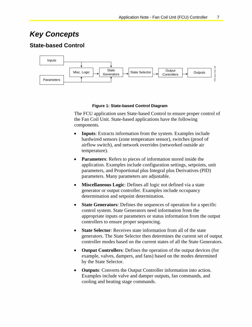
Figure 1: State-based Control Diagram
The FCU application uses State-based Control to ensure proper control of the Fan Coil Unit. State-based applications have the following components.
• Inputs: Extracts information from the system. Examples include hardwired sensors (zone temperature sensor), switches (proof of airflow switch), and network overrides (networked outside air temperature).
• Parameters: Refers to pieces of information stored inside the application. Examples include configuration settings, setpoints, unit parameters, and Proportional plus Integral plus Derivatives (PID) parameters. Many parameters are adjustable.
• Miscellaneous Logic: Defines all logic not defined via a state generator or output controller. Examples include occupancy determination and setpoint determination.
• State Generators: Defines the sequences of operation for a specific control system. State Generators need information from the appropriate inputs or parameters or status information from the output controllers to ensure proper sequencing.
• State Selector: Receives state information from all of the state generators. The State Selector then determines the current set of output controller modes based on the current states of all the State Generators.
• Output Controllers: Defines the operation of the output devices (for example, valves, dampers, and fans) based on the modes determined by the State Selector.
• Outputs: Converts the Output Controller information into action. Examples include valve and damper outputs, fan commands, and cooling and heating stage commands.
8 Application Note - Fan Coil Unit (FCU) Controller
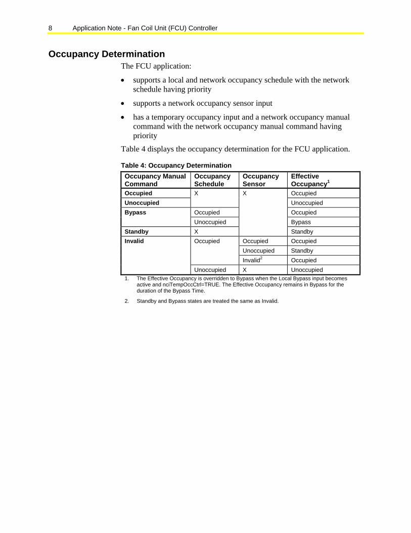
Occupancy Determination The FCU application:
• supports a local and network occupancy schedule with the network schedule having priority
• supports a network occupancy sensor input
• has a temporary occupancy input and a network occupancy manual command with the network occupancy manual command having priority
Table 4 displays the occupancy determination for the FCU application.
Table 4: Occupancy Determination Occupancy Manual Command
Occupancy Schedule
Occupancy Sensor
Effective Occupancy1
Occupied Occupied Unoccupied
X Unoccupied
Occupied Occupied Bypass Unoccupied Bypass
Standby X
X
Standby Occupied Occupied Unoccupied Standby
Occupied
Invalid2 Occupied
Invalid
Unoccupied X Unoccupied 1. The Effective Occupancy is overridden to Bypass when the Local Bypass input becomes
active and nciTempOccCtrl=TRUE. The Effective Occupancy remains in Bypass for the duration of the Bypass Time.
2. Standby and Bypass states are treated the same as Invalid.
Application Note - Fan Coil Unit (FCU) Controller 9
Zone Temperature Control The FCU sequences the controlled devices to control the zone air temperature to a constant setpoint.
Effective Zone Temperature Setpoint Determination The effective (actual) zone temperature setpoint, which the FCU application controls, depends on several inputs including:
• occupied and unoccupied heating and cooling setpoints (configured via cpSetpoints)
• network setpoint override (nviSetpoint)
• network warm/cool adjustment override (nviWarmCoolAdj)
• warm/cool or setpoint adjustment from the zone thermostat
• current effective occupancy state
• zone temperature (from the zone sensor or network zone temperature override nviSpaceTemp)
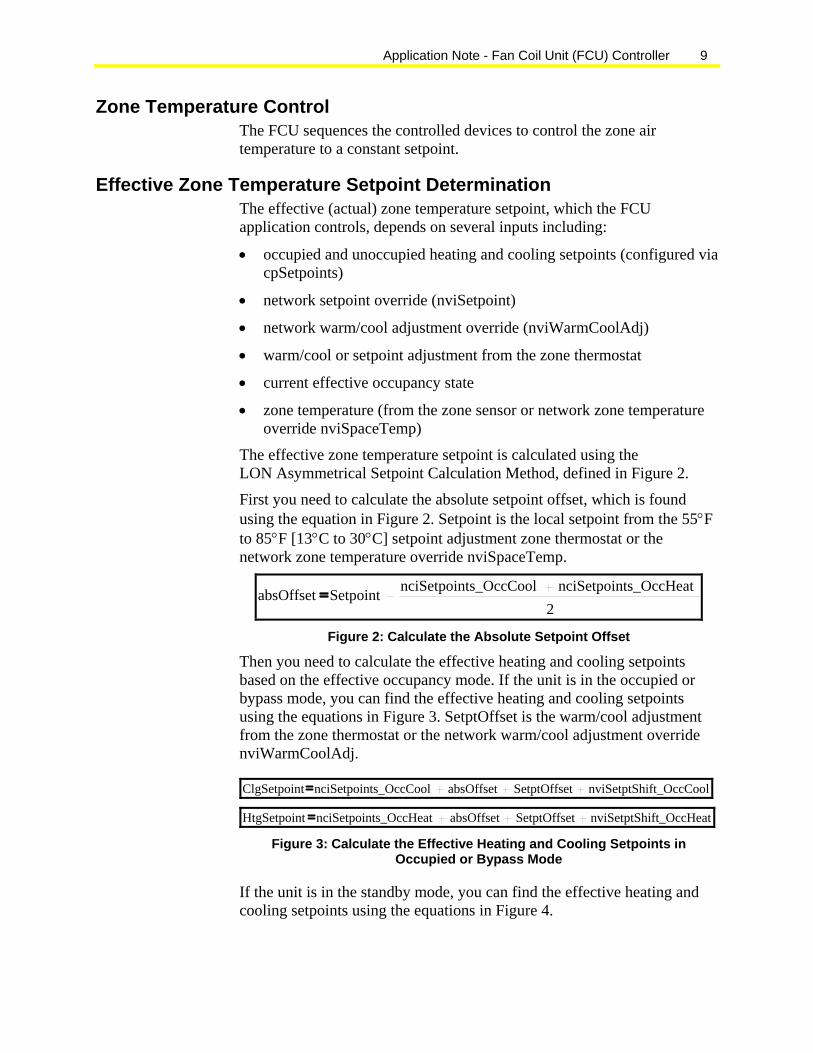
The effective zone temperature setpoint is calculated using the LON Asymmetrical Setpoint Calculation Method, defined in Figure 2.
First you need to calculate the absolute setpoint offset, which is found using the equation in Figure 2. Setpoint is the local setpoint from the 55°F to 85°F [13°C to 30°C] setpoint adjustment zone thermostat or the network zone temperature override nviSpaceTemp.
absOffset Setpoint nciSetpoints_OccCool nciSetpoints_OccHeat2
Figure 2: Calculate the Absolute Setpoint Offset
Then you need to calculate the effective heating and cooling setpoints based on the effective occupancy mode. If the unit is in the occupied or bypass mode, you can find the effective heating and cooling setpoints using the equations in Figure 3. SetptOffset is the warm/cool adjustment from the zone thermostat or the network warm/cool adjustment override nviWarmCoolAdj.
ClgSetpoint nciSetpoints_OccCool absOffset SetptOffset nviSetptShift_OccCool
HtgSetpoint nciSetpoints_OccHeat absOffset SetptOffset nviSetptShift_OccHeat Figure 3: Calculate the Effective Heating and Cooling Setpoints in
Occupied or Bypass Mode
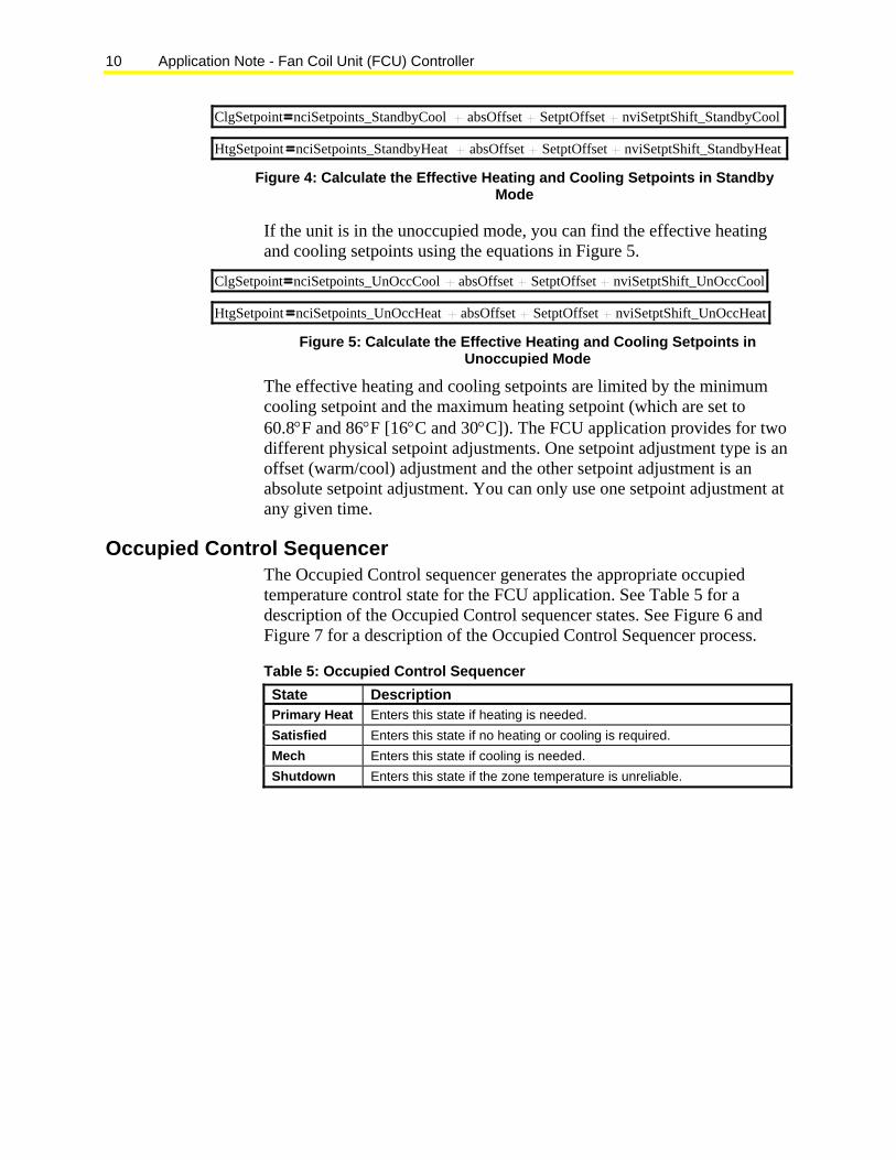
If the unit is in the standby mode, you can find the effective heating and cooling setpoints using the equations in Figure 4.
10 Application Note - Fan Coil Unit (FCU) Controller
ClgSetpoint nciSetpoints_StandbyCool absOffset SetptOffset nviSetptShift_StandbyCool
HtgSetpoint nciSetpoints_StandbyHeat absOffset SetptOffset nviSetptShift_StandbyHeat Figure 4: Calculate the Effective Heating and Cooling Setpoints in Standby
Mode
If the unit is in the unoccupied mode, you can find the effective heating and cooling setpoints using the equations in Figure 5.
ClgSetpoint nciSetpoints_UnOccCool absOffset SetptOffset nviSetptShift_UnOccCool
HtgSetpoint nciSetpoints_UnOccHeat absOffset SetptOffset nviSetptShift_UnOccHeat Figure 5: Calculate the Effective Heating and Cooling Setpoints in
Unoccupied Mode
The effective heating and cooling setpoints are limited by the minimum cooling setpoint and the maximum heating setpoint (which are set to 60.8°F and 86°F [16°C and 30°C]). The FCU application provides for two different physical setpoint adjustments. One setpoint adjustment type is an offset (warm/cool) adjustment and the other setpoint adjustment is an absolute setpoint adjustment. You can only use one setpoint adjustment at any given time.
Occupied Control Sequencer The Occupied Control sequencer generates the appropriate occupied temperature control state for the FCU application. See Table 5 for a description of the Occupied Control sequencer states. See Figure 6 and Figure 7 for a description of the Occupied Control Sequencer process.
Table 5: Occupied Control Sequencer State Description Primary Heat Enters this state if heating is needed. Satisfied Enters this state if no heating or cooling is required. Mech Enters this state if cooling is needed. Shutdown Enters this state if the zone temperature is unreliable.

Application Note - Fan Coil Unit (FCU) Controller 11
Start
Heating not required Heating required
Zone Temp unreliable
Shutdown
Zone Temp reliable
Primary Heat
Primary heat not responding heating not required
Heating not required and Heat PID saturated low
Satisfied
A large heating setpoint change was made and heating is not required
and fast sequence is enabled.
FIG
:zon
e_oc
c_ct
rl_se
q_he
at
Figure 6: Zone Occupied Control Sequencer – Heating
Start
Cooling not required Cooling required
Zone Temp unreliable
Shutdown
Zone Temp reliable
Mech
Mech Cooling not responding and Cooling not required
Cooling not required and Cooling PID
saturated low
Satisfied
A large cooling setpoint change was made and cooling is not required
and fast sequence is enabled.
FIG
:zon
e_oc
c_ct
rl_se
q_co
ol
Figure 7: Zone Occupied Control Sequencer – Cooling
12 Application Note - Fan Coil Unit (FCU) Controller
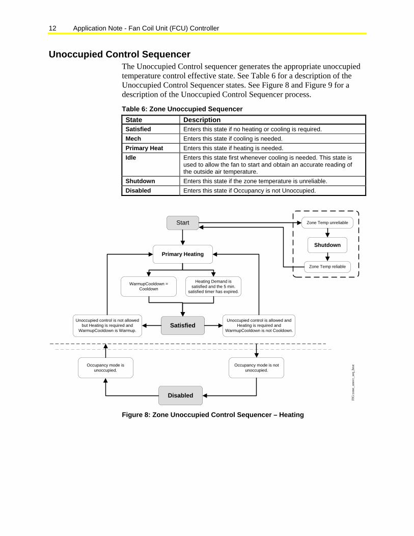
Unoccupied Control Sequencer The Unoccupied Control sequencer generates the appropriate unoccupied temperature control effective state. See Table 6 for a description of the Unoccupied Control Sequencer states. See Figure 8 and Figure 9 for a description of the Unoccupied Control Sequencer process.
Table 6: Zone Unoccupied Sequencer State Description Satisfied Enters this state if no heating or cooling is required. Mech Enters this state if cooling is needed. Primary Heat Enters this state if heating is needed. Idle Enters this state first whenever cooling is needed. This state is
used to allow the fan to start and obtain an accurate reading of the outside air temperature.
Shutdown Enters this state if the zone temperature is unreliable. Disabled Enters this state if Occupancy is not Unoccupied.
Start Zone Temp unreliable
Shutdown
Zone Temp reliable
Primary Heating
Heating Demand is satisfied and the 5 min.
satisfied timer has expired.
SatisfiedUnoccupied control is allowed and
Heating is required and WarmupCooldown is not Cooldown.
Unoccupied control is not allowed but Heating is required and
WarmupCooldown is Warmup.
Occupancy mode is unoccupied.
Occupancy mode is not unoccupied.
Disabled
WarmupCooldown = Cooldown
FIG
:zon
e_un
occ_
seq_
heat
Figure 8: Zone Unoccupied Control Sequencer – Heating
Application Note - Fan Coil Unit (FCU) Controller 13
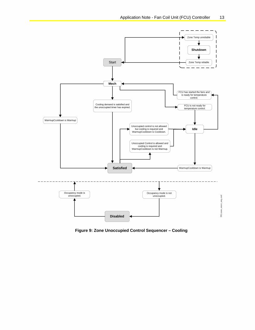
Start
Satisfied
Occupancy mode is unoccupied.
Occupancy mode is not unoccupied.
Disabled
Mech
FCU has started the fans and is ready for temperature
control.
Idle
FCU is not ready for temperature control.
WarmupCooldown is Warmup
Unoccupied control is not allowed but cooling is required and
WarmupCooldown is Cooldown.
Unoccupied Control is allowed and cooling is required and
WarmupCooldown is not Warmup.
WarmupCcoldown is Warmup
Cooling demand is satisfied and the unoccupied timer has expired.
Zone Temp unreliable
Shutdown
Zone Temp reliable
FI
G:z
one_
unoc
c_se
q_co
ol
Figure 9: Zone Unoccupied Control Sequencer – Cooling
14 Application Note - Fan Coil Unit (FCU) Controller
Sequencers Emergency Heat The application determines the Emergency Heat status (On or Off) based on a comparison of the zone temperature with the Emergency Heat Setpoint and Emergency Heat Differential. See Table 7.
Table 7: Emergency Heat State Description On Emergency Heat is required. Off Emergency Heat is not required.
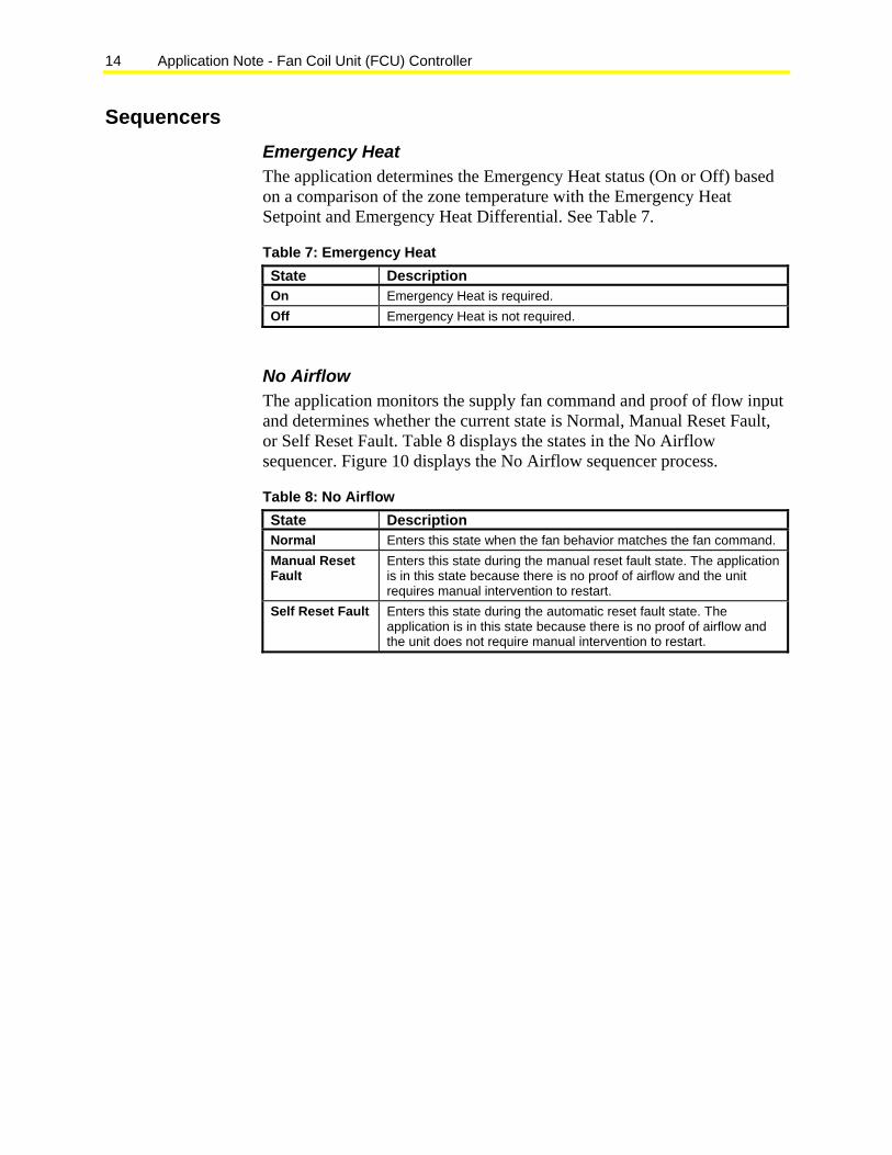
No Airflow The application monitors the supply fan command and proof of flow input and determines whether the current state is Normal, Manual Reset Fault, or Self Reset Fault. Table 8 displays the states in the No Airflow sequencer. Figure 10 displays the No Airflow sequencer process.
Table 8: No Airflow State Description Normal Enters this state when the fan behavior matches the fan command. Manual Reset Fault
Enters this state during the manual reset fault state. The application is in this state because there is no proof of airflow and the unit requires manual intervention to restart.
Self Reset Fault Enters this state during the automatic reset fault state. The application is in this state because there is no proof of airflow and the unit does not require manual intervention to restart.
Application Note - Fan Coil Unit (FCU) Controller 15
Normal
Fan status did not start before the startup delay expired.
Fan status was lost for more than the Flow Debounce time.
Fan status on for more than the flow debounce time.
Manual resetSupply fan commanded off
NOT (Manual Reset Required)
Manual Reset Fault
Manual Reset Required
Self Reset Fault
FIG
:no_
air_
flo_2
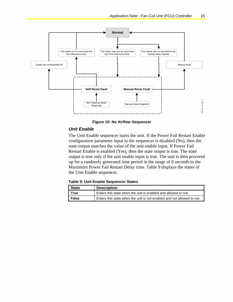
Figure 10: No Airflow Sequencer
Unit Enable The Unit Enable sequencer starts the unit. If the Power Fail Restart Enable configuration parameter input to the sequencer is disabled (No), then the state output matches the value of the unit enable input. If Power Fail Restart Enable is enabled (Yes), then the state output is true. The state output is true only if the unit enable input is true. The unit is then powered up for a randomly generated time period in the range of 0 seconds to the Maximum Power Fail Restart Delay time. Table 9 displays the states of the Unit Enable sequencer.
Table 9: Unit Enable Sequencer States State Description True Enters this state when the unit is enabled and allowed to run. False Enters this state when the unit is not enabled and not allowed to run.
16 Application Note - Fan Coil Unit (FCU) Controller
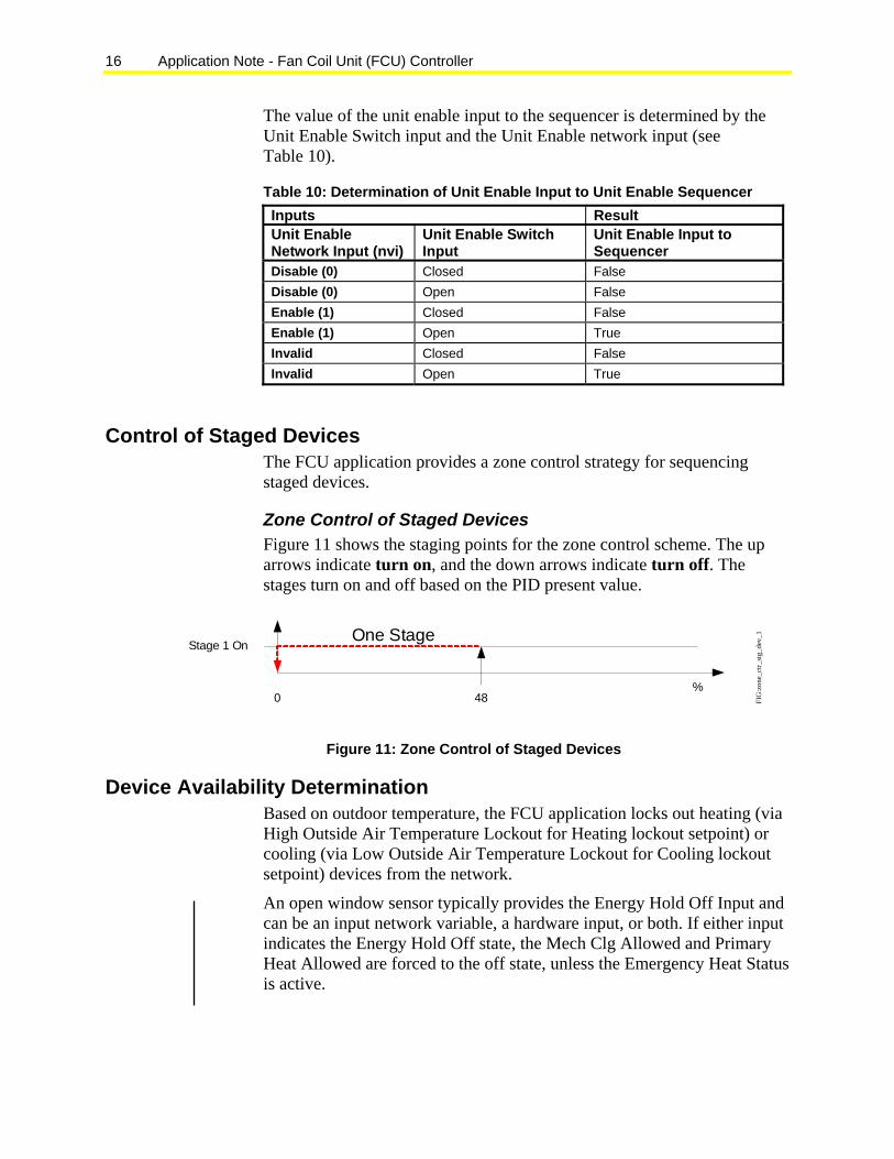
The value of the unit enable input to the sequencer is determined by the Unit Enable Switch input and the Unit Enable network input (see Table 10).
Table 10: Determination of Unit Enable Input to Unit Enable Sequencer Inputs Result Unit Enable Network Input (nvi)
Unit Enable Switch Input
Unit Enable Input to Sequencer
Disable (0) Closed False Disable (0) Open False Enable (1) Closed False Enable (1) Open True Invalid Closed False Invalid Open True
Control of Staged Devices The FCU application provides a zone control strategy for sequencing staged devices.
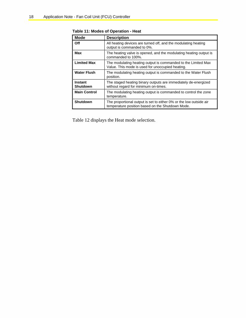
Zone Control of Staged Devices Figure 11 shows the staging points for the zone control scheme. The up arrows indicate turn on, and the down arrows indicate turn off. The stages turn on and off based on the PID present value.
Stage 1 On
480
One Stage
%
FIG
:zon
e_ct
r_st
g_de
v_1
Figure 11: Zone Control of Staged Devices
Device Availability Determination Based on outdoor temperature, the FCU application locks out heating (via High Outside Air Temperature Lockout for Heating lockout setpoint) or cooling (via Low Outside Air Temperature Lockout for Cooling lockout setpoint) devices from the network.
An open window sensor typically provides the Energy Hold Off Input and can be an input network variable, a hardware input, or both. If either input indicates the Energy Hold Off state, the Mech Clg Allowed and Primary Heat Allowed are forced to the off state, unless the Emergency Heat Status is active.

Application Note - Fan Coil Unit (FCU) Controller 17
The current state of the hardware input is available in the output network variable Energy Hold Off for monitoring purposes. This input also provides the status of a hardwired window contact to another controller in the same area.
You typically strap the condensation sensor to the chilled water pipe upstream of the control valve to a chilled ceiling. The sensor is used to minimize the effects of condensation in the ceiling area that would damage ceiling material and the equipment in the space below.
The Condensation Sensor Input can be an input network variable, hardware input connected to a condensation sensor, or both. When either input indicates the Condensation State, the Cooling Output is forced to the minimum output level (normally zero), and the status is indicated in the output network variable Condensation Sensor for monitoring purposes. The current state of the hardware input is available in the output network variable Condensation to provide the status of a hardwired condensation sensor to another controller in the same area.
Output Device Control Heating The FCU application supports the following heat control options:
• none
• staged heating (1 stage)
• Face and Bypass Damper (FBPD) with two-position valve
• proportional valve
• two-pipe Face and Bypass Damper with two-position valve
• two-pipe proportional valve
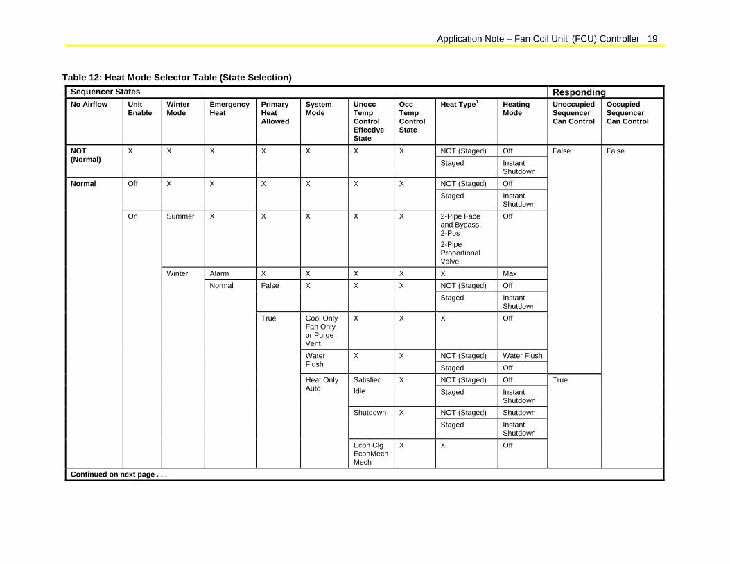
Modes of Operation Table 11 displays the modes of operation for the Heat module.
18 Application Note - Fan Coil Unit (FCU) Controller
Table 11: Modes of Operation - Heat Mode Description Off All heating devices are turned off, and the modulating heating
output is commanded to 0%. Max The heating valve is opened, and the modulating heating output is
commanded to 100%. Limited Max The modulating heating output is commanded to the Limited Max
Value. This mode is used for unoccupied heating. Water Flush The modulating heating output is commanded to the Water Flush
position. Instant Shutdown
The staged heating binary outputs are immediately de-energized without regard for minimum on-times.
Main Control The modulating heating output is commanded to control the zone temperature.
Shutdown The proportional output is set to either 0% or the low outside air temperature position based on the Shutdown Mode.
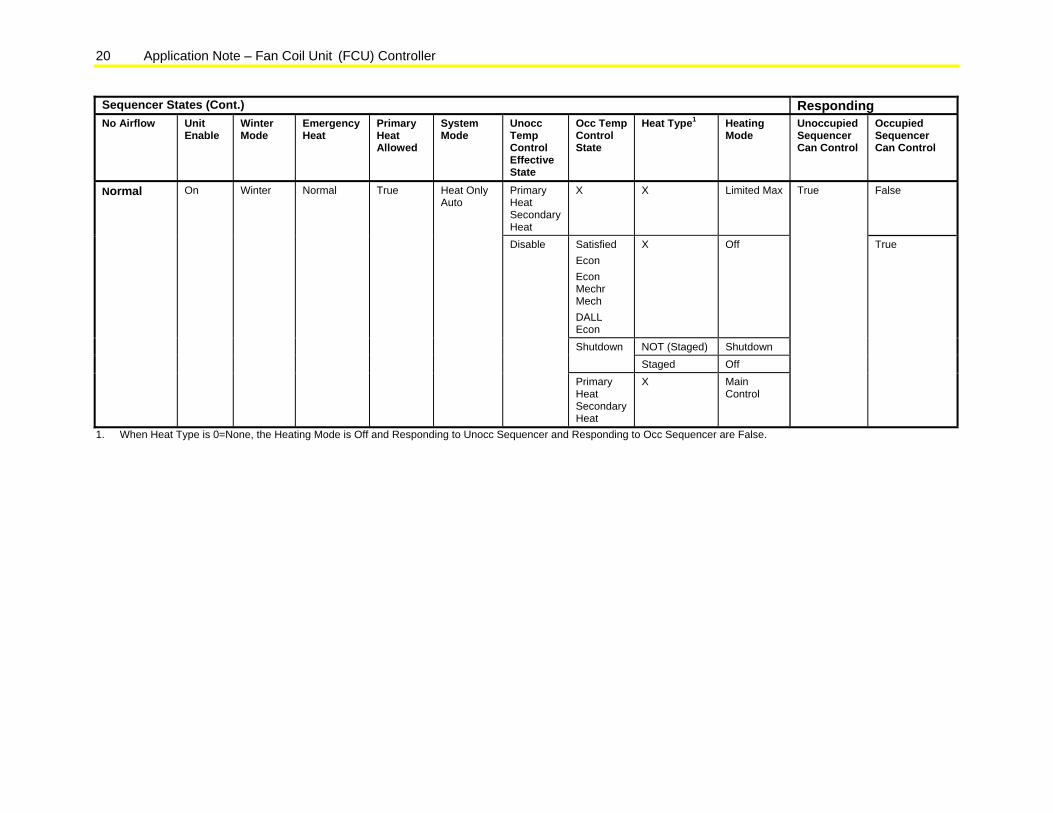
Table 12 displays the Heat mode selection.
Application Note – Fan Coil Unit (FCU) Controller 19
Table 12: Heat Mode Selector Table (State Selection) Sequencer States Responding No Airflow Unit
Enable Winter Mode
Emergency Heat
Primary Heat Allowed
System Mode
Unocc Temp Control Effective State
Occ Temp Control State
Heat Type1 Heating Mode
Unoccupied Sequencer Can Control
Occupied Sequencer Can Control
NOT (Staged) Off NOT (Normal)
X X X X X X X Staged Instant
Shutdown NOT (Staged) Off Off X X X X X X Staged Instant
Shutdown Summer X X X X X 2-Pipe Face
and Bypass, 2-Pos 2-Pipe Proportional Valve
Off
Alarm X X X X X Max NOT (Staged) Off False X X X Staged Instant
Shutdown Cool Only Fan Only or Purge Vent
X X X Off
NOT (Staged) Water Flush Water Flush
X X Staged Off
False
NOT (Staged) Off Satisfied Idle
X Staged Instant
Shutdown NOT (Staged) Shutdown Shutdown X Staged Instant
Shutdown
Normal
On
Winter Normal
True
Heat Only Auto
Econ Clg EconMech Mech
X X Off
True
False
Continued on next page . . .
20 Application Note – Fan Coil Unit (FCU) Controller
Sequencer States (Cont.) Responding No Airflow Unit
Enable Winter Mode
Emergency Heat
Primary Heat Allowed
System Mode
Unocc Temp Control Effective State
Occ Temp Control State
Heat Type1 Heating Mode
Unoccupied Sequencer Can Control
Occupied Sequencer Can Control
Primary Heat Secondary Heat
X X Limited Max False
Satisfied Econ Econ Mechr Mech DALL Econ
X Off
NOT (Staged) Shutdown Shutdown Staged Off
Normal On Winter Normal True Heat Only Auto
Disable
Primary Heat Secondary Heat
X Main Control
True
True
1. When Heat Type is 0=None, the Heating Mode is Off and Responding to Unocc Sequencer and Responding to Occ Sequencer are False.
Application Note – Fan Coil Unit (FCU) Controller 21
Cooling The FCU application supports the following cooling control options:
• none
• staged cooling (one stage)
• Face and Bypass Damper with two-position valve
• proportional valve
• two-pipe Face and Bypass Damper with two-position valve
• two-pipe proportional valve
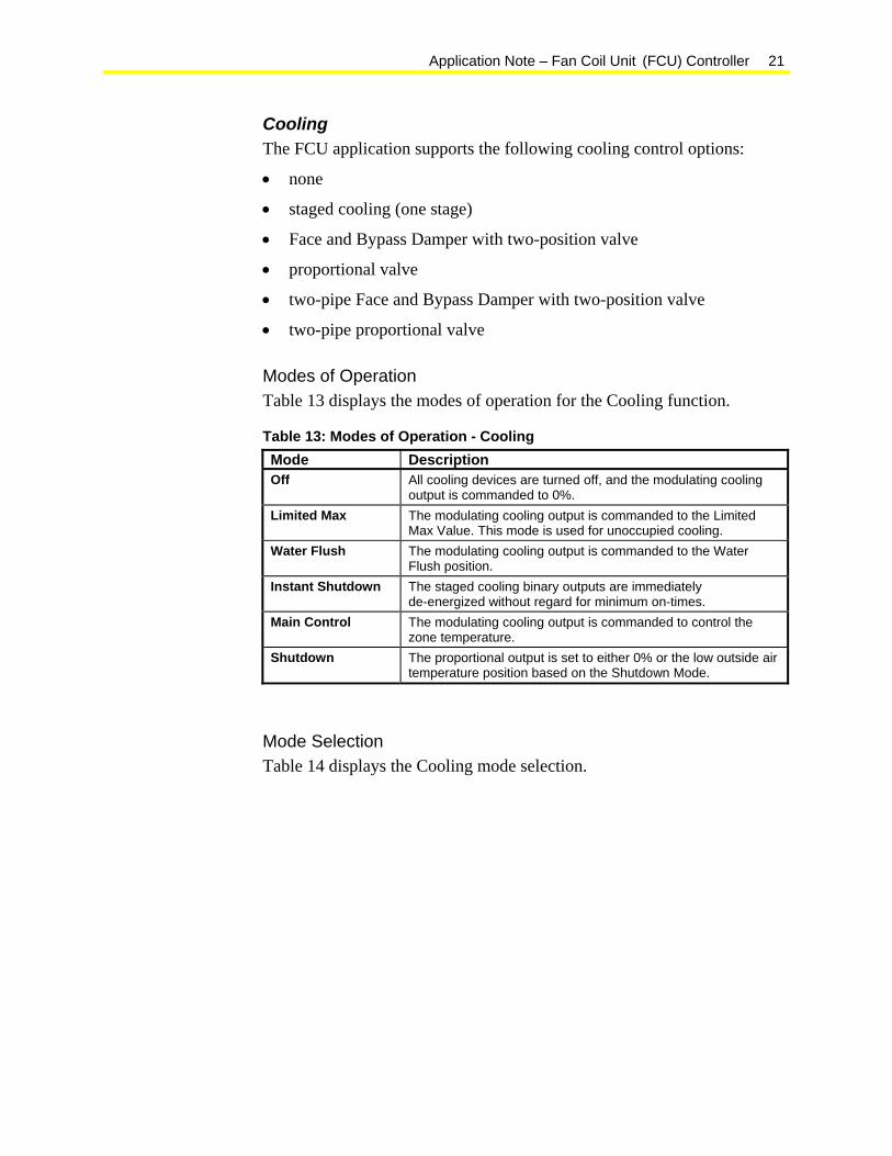
Modes of Operation Table 13 displays the modes of operation for the Cooling function.
Table 13: Modes of Operation - Cooling Mode Description Off All cooling devices are turned off, and the modulating cooling
output is commanded to 0%. Limited Max The modulating cooling output is commanded to the Limited
Max Value. This mode is used for unoccupied cooling. Water Flush The modulating cooling output is commanded to the Water
Flush position. Instant Shutdown The staged cooling binary outputs are immediately
de-energized without regard for minimum on-times. Main Control The modulating cooling output is commanded to control the
zone temperature. Shutdown The proportional output is set to either 0% or the low outside air
temperature position based on the Shutdown Mode.
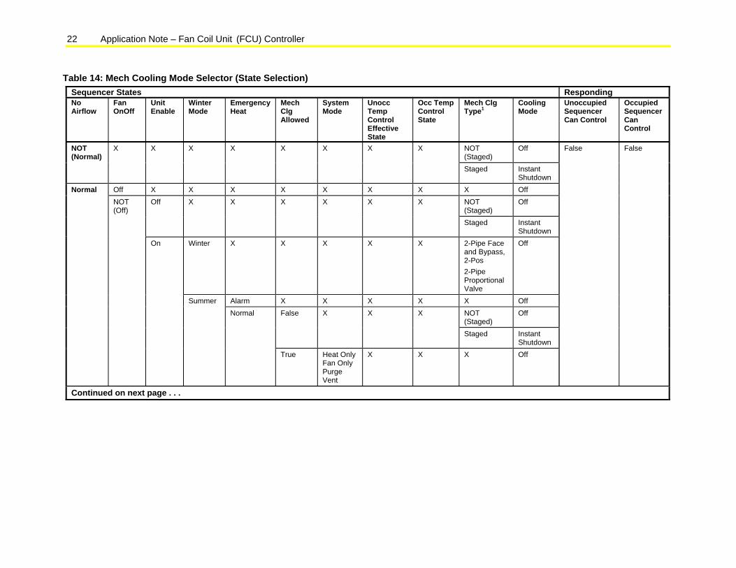
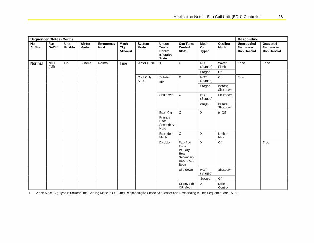
Mode Selection Table 14 displays the Cooling mode selection.
22 Application Note – Fan Coil Unit (FCU) Controller
Table 14: Mech Cooling Mode Selector (State Selection) Sequencer States Responding No Airflow
Fan OnOff
Unit Enable
Winter Mode
Emergency Heat
Mech Clg Allowed
System Mode
Unocc Temp Control Effective State
Occ Temp Control State
Mech Clg Type1
Cooling Mode
Unoccupied Sequencer Can Control
Occupied Sequencer Can Control
NOT (Staged)
Off NOT (Normal)
X X X X X X X X
Staged Instant Shutdown
Off X X X X X X X X Off NOT (Staged)
Off Off X X X X X X
Staged Instant Shutdown
Winter X X X X X 2-Pipe Face and Bypass, 2-Pos 2-Pipe Proportional Valve
Off
Alarm X X X X X Off NOT (Staged)
Off False X X X
Staged Instant Shutdown
Normal NOT (Off)
On
Summer Normal
True Heat Only Fan Only Purge Vent
X X X Off
False False
Continued on next page . . .
Application Note – Fan Coil Unit (FCU) Controller 23
Sequencer States (Cont.) Responding No Airflow
Fan OnOff
Unit Enable
Winter Mode
Emergency Heat
Mech Clg Allowed
System Mode
Unocc Temp Control Effective State
Occ Temp Control State
Mech Clg Type1
Cooling Mode
Unoccupied Sequencer Can Control
Occupied Sequencer Can Control
NOT (Staged)
Water Flush
Water Flush X X
Staged Off
False
NOT (Staged)
Off Satisfied Idle
X
Staged Instant Shutdown
NOT (Staged)
Shutdown Shutdown X
Staged Instant Shutdown
Econ Clg Primary Heat Secondary Heat
X X 0=Off
EconMechMech
X X Limited Max
False
Satisfied Econ Primary Heat Secondary Heat DALL Econ
X Off
NOT (Staged)
Shutdown Shutdown
Staged Off
Normal NOT (Off)
On Summer Normal True
Cool Only Auto
Disable
EconMech OR Mech
X Main Control
True
True
1. When Mech Clg Type is 0=None, the Cooling Mode is OFF and Responding to Unocc Sequencer and Responding to Occ Sequencer are FALSE.
24 Application Note – Fan Coil Unit (FCU) Controller
Two-Pipe Coil The FCU application supports a two-pipe cooling coil. The two-pipe coil supports proportional valve control and Face and Bypass Damper control with a two-position valve. See Heating and Cooling for modes of operation.
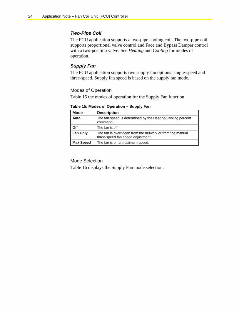
Supply Fan The FCU application supports two supply fan options: single-speed and three-speed. Supply fan speed is based on the supply fan mode.
Modes of Operation Table 15 the modes of operation for the Supply Fan function.
Table 15: Modes of Operation – Supply Fan Mode Description Auto The fan speed is determined by the Heating/Cooling percent
command. Off The fan is off. Fan Only The fan is overridden from the network or from the manual
three-speed fan speed adjustment. Max Speed The fan is on at maximum speed.
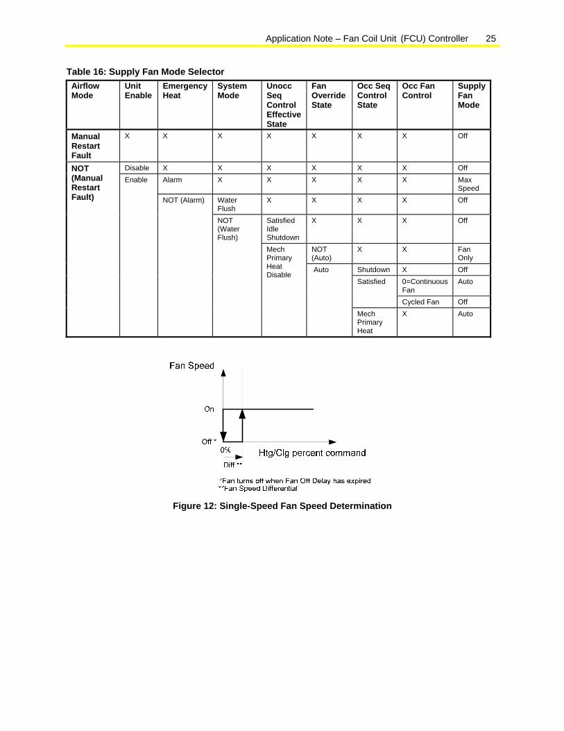
Mode Selection Table 16 displays the Supply Fan mode selection.
Application Note – Fan Coil Unit (FCU) Controller 25
Table 16: Supply Fan Mode Selector Airflow Mode
Unit Enable
Emergency Heat
System Mode
Unocc Seq Control Effective State
Fan Override State
Occ Seq Control State
Occ Fan Control
Supply Fan Mode
Manual Restart Fault
X X X X X X X Off
Disable X X X X X X Off Alarm X X X X X Max
Speed Water Flush
X X X X Off
Satisfied Idle Shutdown
X X X Off
NOT (Auto)
X X Fan Only
Shutdown X Off 0=Continuous Fan
Auto Satisfied
Cycled Fan Off
NOT (Manual Restart Fault)
Enable
NOT (Alarm)
NOT (Water Flush)
Mech Primary Heat Disable
Auto
Mech Primary Heat
X Auto
Figure 12: Single-Speed Fan Speed Determination
26 Application Note – Fan Coil Unit (FCU) Controller
Off *0%
Fan Speed
Htg/Clg percent command
30% 60% 90%
Low
Med
High
*Fan turns off when Fan Off Delay has expired
Diff **
**Fan Speed Differential
Diff **Diff **
FIG
:3_s
pd_f
an_s
pd
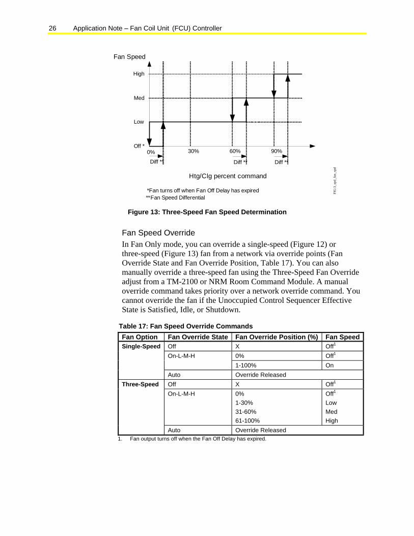
Figure 13: Three-Speed Fan Speed Determination
Fan Speed Override In Fan Only mode, you can override a single-speed (Figure 12) or three-speed (Figure 13) fan from a network via override points (Fan Override State and Fan Override Position, Table 17). You can also manually override a three-speed fan using the Three-Speed Fan Override adjust from a TM-2100 or NRM Room Command Module. A manual override command takes priority over a network override command. You cannot override the fan if the Unoccupied Control Sequencer Effective State is Satisfied, Idle, or Shutdown.
Table 17: Fan Speed Override Commands Fan Option Fan Override State Fan Override Position (%) Fan Speed
Off X Off1 0% Off1 On-L-M-H 1-100% On
Single-Speed
Auto Override Released Off X Off1 On-L-M-H 0%
1-30% 31-60% 61-100%
Off1 Low Med High
Three-Speed
Auto Override Released 1. Fan output turns off when the Fan Off Delay has expired.
Application Note – Fan Coil Unit (FCU) Controller 27
Occupied Fan Control You can configure the Supply Fan to either run continuously or to turn off when the unit is in an occupied mode and satisfied (no heating or cooling is required). When the configuration parameter Occupied Fan Control is set to Constant Fan, the fan continues to run at minimum speed when no heating or cooling is required. When the parameter is set to Cycle Fan, the fan turns off during satisfied periods.
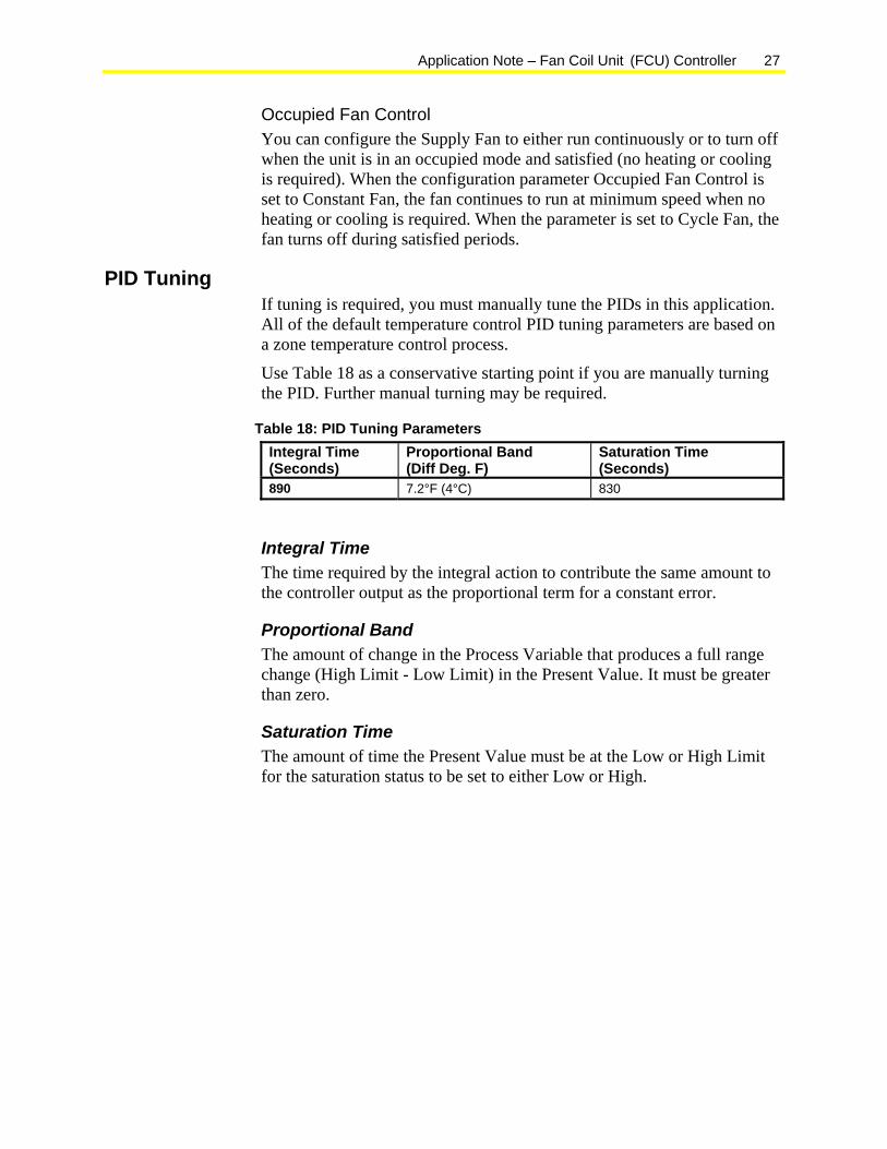
PID Tuning If tuning is required, you must manually tune the PIDs in this application. All of the default temperature control PID tuning parameters are based on a zone temperature control process.
Use Table 18 as a conservative starting point if you are manually turning the PID. Further manual turning may be required.
Table 18: PID Tuning Parameters Integral Time (Seconds)
Proportional Band (Diff Deg. F)
Saturation Time (Seconds)
890 7.2°F (4°C) 830
Integral Time The time required by the integral action to contribute the same amount to the controller output as the proportional term for a constant error.
Proportional Band The amount of change in the Process Variable that produces a full range change (High Limit - Low Limit) in the Present Value. It must be greater than zero.
Saturation Time The amount of time the Present Value must be at the Low or High Limit for the saturation status to be set to either Low or High.
28 Application Note – Fan Coil Unit (FCU) Controller
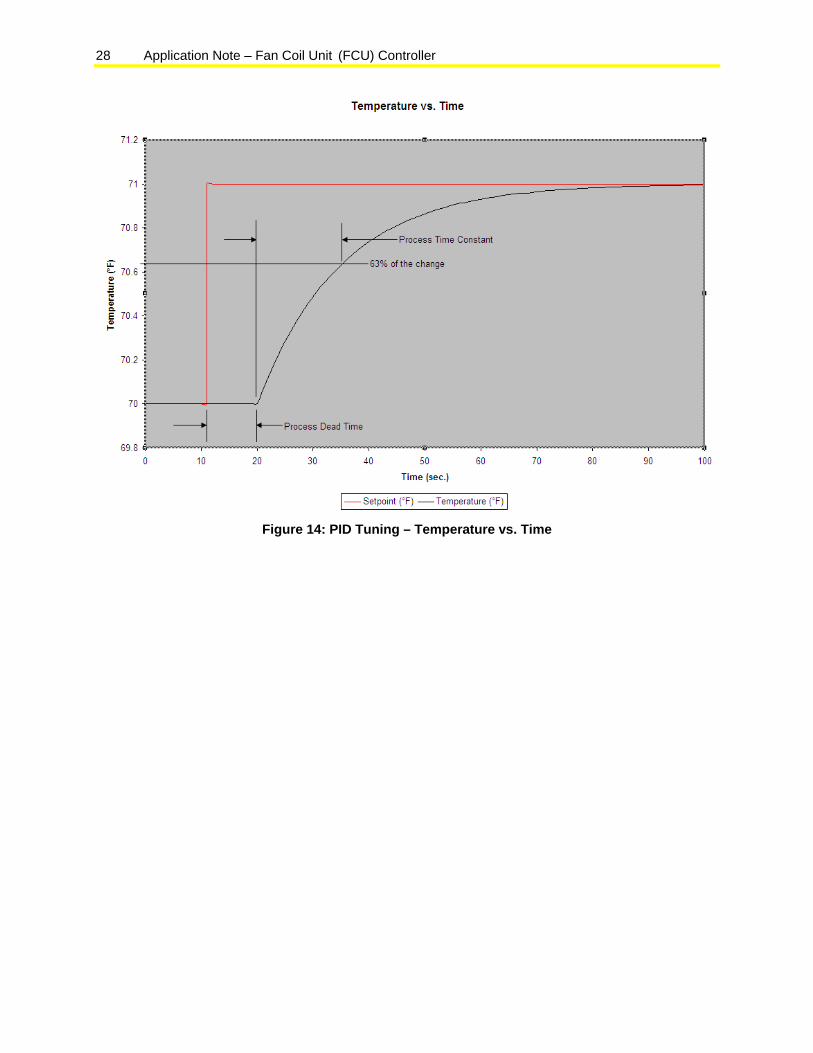
Figure 14: PID Tuning – Temperature vs. Time
Application Note – Fan Coil Unit (FCU) Controller 29
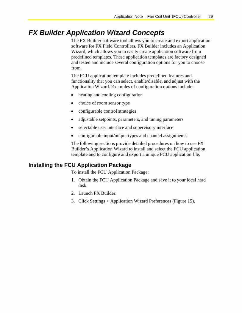
FX Builder Application Wizard Concepts The FX Builder software tool allows you to create and export application software for FX Field Controllers. FX Builder includes an Application Wizard, which allows you to easily create application software from predefined templates. These application templates are factory designed and tested and include several configuration options for you to choose from.
The FCU application template includes predefined features and functionality that you can select, enable/disable, and adjust with the Application Wizard. Examples of configuration options include:
• heating and cooling configuration
• choice of room sensor type
• configurable control strategies
• adjustable setpoints, parameters, and tuning parameters
• selectable user interface and supervisory interface
• configurable input/output types and channel assignments
The following sections provide detailed procedures on how to use FX Builder’s Application Wizard to install and select the FCU application template and to configure and export a unique FCU application file.
Installing the FCU Application Package To install the FCU Application Package:
1. Obtain the FCU Application Package and save it to your local hard disk.
2. Launch FX Builder.
3. Click Settings > Application Wizard Preferences (Figure 15).

30 Application Note – Fan Coil Unit (FCU) Controller
Figure 15: Settings > Application Wizard Preferences Menu
The Application Wizard Preferences dialog box appears (Figure 16).
Figure 16: Application Wizard Preferences Dialog Box without Packages
Installed
4. Under File Preferences, select the documents you want to generate. Documentation types which you can select include:
• Hardware I/O Documentation
• Protocol Documentation
• Network Protocol Files (N2 Print Files, LON Resource files)
Application Note – Fan Coil Unit (FCU) Controller 31
Note: The default is to generate all three types of documentation. We highly recommend you keep the preferences at these defaults, so that all documentation types are generated.
5. If desired, change the File Location to where the generated files are exported.
6. Click Install… and navigate to the location of the FCU Application Package as performed in Step 1.
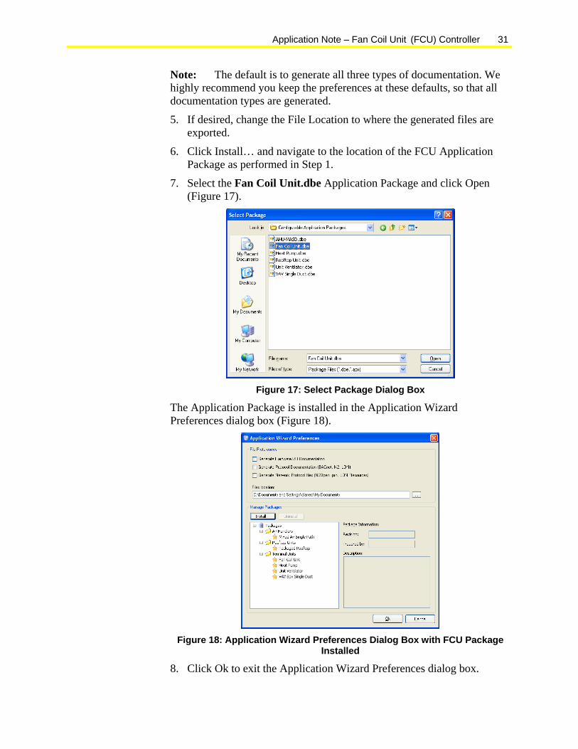
7. Select the Fan Coil Unit.dbe Application Package and click Open (Figure 17).
Figure 17: Select Package Dialog Box
The Application Package is installed in the Application Wizard Preferences dialog box (Figure 18).
Figure 18: Application Wizard Preferences Dialog Box with FCU Package
Installed
8. Click Ok to exit the Application Wizard Preferences dialog box.
32 Application Note – Fan Coil Unit (FCU) Controller
Selecting the FCU Application Template To select the FCU Application Template:
1. Open FX Builder.
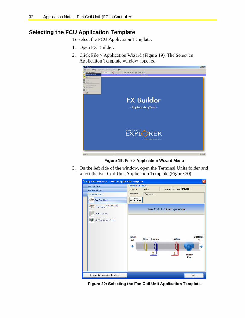
2. Click File > Application Wizard (Figure 19). The Select an Application Template window appears.
Figure 19: File > Application Wizard Menu
3. On the left side of the window, open the Terminal Units folder and select the Fan Coil Unit Application Template (Figure 20).
Figure 20: Selecting the Fan Coil Unit Application Template

Application Note – Fan Coil Unit (FCU) Controller 33
4. Click Next. A status bar appears while the selected application template and plug-ins are loaded into FX Builder (Figure 21).
Figure 21: Loading Application Status Bar
The Configure plug-in appears when the application is loaded (Figure 22).
Configuring the FCU Application The Configure dialog contains tabbed views of the control strategy configuration options, setpoints, and parameters that you can select and adjust in the FCU application.
Configuring the Control Strategy To configure the control strategy:
1. Click the Configuration tab. The FCU application’s control strategy configuration options and default values appear (Figure 22).
Figure 22: Fan Coil Unit Configuration Plug-in
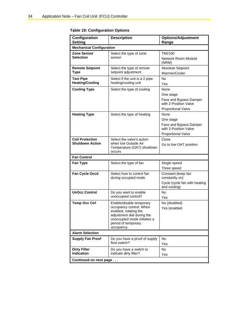
2. Modify the configuration settings as needed. Use Table 19 as a reference.
34 Application Note – Fan Coil Unit (FCU) Controller
Table 19: Configuration Options
Configuration Setting
Description Options/Adjustment Range
Mechanical Configuration Zone Sensor Selection
Select the type of zone sensor
TM2100 Network Room Module (NRM)
Remote Setpoint Type
Select the type of remote setpoint adjustment
Absolute Setpoint Warmer/Cooler
Two Pipe Heating/Cooling
Select if the unit is a 2-pipe heating/cooling unit
No Yes
Cooling Type Select the type of cooling None One stage Face and Bypass Damper with 2-Position Valve Proportional Valve
Heating Type Select the type of heating None One stage Face and Bypass Damper with 2-Position Valve Proportional Valve
Coil Protection Shutdown Action
Select the valve’s action when low Outside Air Temperature (OAT) shutdown occurs
Close Go to low OAT position
Fan Control Fan Type Select the type of fan Single speed
Three speed Fan Cycle Occd Select how to control fan
during occupied mode Constant (keep fan constantly on) Cycle (cycle fan with heating and cooling)
UnOcc Control Do you want to enable unoccupied control?
No Yes
Temp Occ Ctrl Enable/disable temporary occupancy control. When enabled, rotating the adjustment dial during the unoccupied mode initiates a period of temporary occupancy.
No (disabled) Yes (enabled
Alarm Selection Supply Fan Proof Do you have a proof of supply
flow switch? No Yes
Dirty Filter Indication
Do you have a switch to indicate dirty filter?
No Yes
Continued on next page . . .
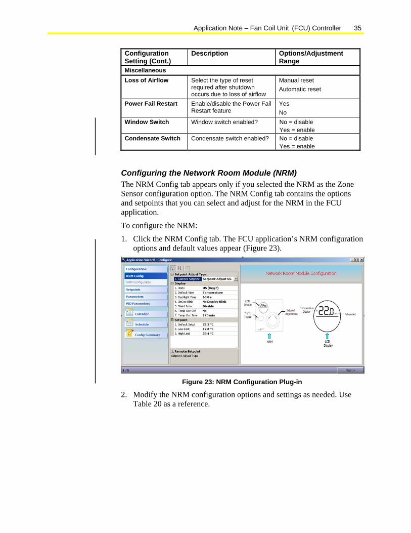
Application Note – Fan Coil Unit (FCU) Controller 35
Configuration Setting (Cont.)
Description Options/Adjustment Range
Miscellaneous Loss of Airflow Select the type of reset
required after shutdown occurs due to loss of airflow
Manual reset Automatic reset
Power Fail Restart Enable/disable the Power Fail Restart feature
Yes No
Window Switch Window switch enabled? No = disable Yes = enable
Condensate Switch Condensate switch enabled? No = disable Yes = enable
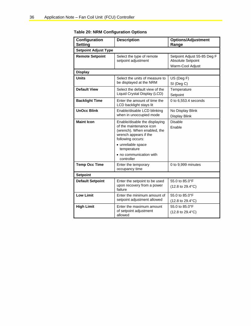
Configuring the Network Room Module (NRM) The NRM Config tab appears only if you selected the NRM as the Zone Sensor configuration option. The NRM Config tab contains the options and setpoints that you can select and adjust for the NRM in the FCU application.
To configure the NRM:
1. Click the NRM Config tab. The FCU application’s NRM configuration options and default values appear (Figure 23).
Figure 23: NRM Configuration Plug-in
2. Modify the NRM configuration options and settings as needed. Use Table 20 as a reference.
36 Application Note – Fan Coil Unit (FCU) Controller
Table 20: NRM Configuration Options
Configuration Setting
Description Options/Adjustment Range
Setpoint Adjust Type Remote Setpoint Select the type of remote
setpoint adjustment Setpoint Adjust 55-85 Deg F Absolute Setpoint Warm-Cool Adjust
Display Units Select the units of measure to
be displayed at the NRM US (Deg F) SI (Deg C)
Default View Select the default view of the Liquid Crystal Display (LCD)
Temperature Setpoint
Backlight Time Enter the amount of time the LCD backlight stays lit
0 to 6,553.4 seconds
UnOcc Blink Enable/disable LCD blinking when in unoccupied mode
No Display Blink Display Blink
Maint Icon Enable/disable the displaying of the maintenance icon (wrench). When enabled, the wrench appears if the following occurs: • unreliable space
temperature • no communication with
controller
Disable Enable
Temp Occ Time Enter the temporary occupancy time
0 to 9,999 minutes
Setpoint Default Setpoint Enter the setpoint to be used
upon recovery from a power failure
55.0 to 85.0°F (12.8 to 29.4°C)
Low Limit Enter the minimum amount of setpoint adjustment allowed
55.0 to 85.0°F (12.8 to 29.4°C)
High Limit Enter the maximum amount of setpoint adjustment allowed
55.0 to 85.0°F (12.8 to 29.4°C)
Application Note – Fan Coil Unit (FCU) Controller 37
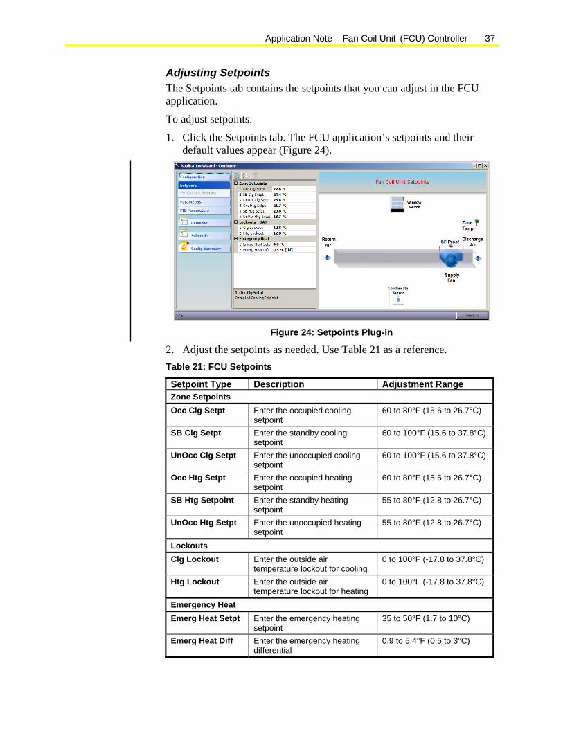
Adjusting Setpoints The Setpoints tab contains the setpoints that you can adjust in the FCU application.
To adjust setpoints:
1. Click the Setpoints tab. The FCU application’s setpoints and their default values appear (Figure 24).
Figure 24: Setpoints Plug-in
2. Adjust the setpoints as needed. Use Table 21 as a reference. Table 21: FCU Setpoints
Setpoint Type Description Adjustment Range Zone Setpoints Occ Clg Setpt Enter the occupied cooling
setpoint 60 to 80°F (15.6 to 26.7°C)
SB Clg Setpt Enter the standby cooling setpoint
60 to 100°F (15.6 to 37.8°C)
UnOcc Clg Setpt Enter the unoccupied cooling setpoint
60 to 100°F (15.6 to 37.8°C)
Occ Htg Setpt Enter the occupied heating setpoint
60 to 80°F (15.6 to 26.7°C)
SB Htg Setpoint Enter the standby heating setpoint
55 to 80°F (12.8 to 26.7°C)
UnOcc Htg Setpt Enter the unoccupied heating setpoint
55 to 80°F (12.8 to 26.7°C)
Lockouts Clg Lockout Enter the outside air
temperature lockout for cooling 0 to 100°F (-17.8 to 37.8°C)
Htg Lockout Enter the outside air temperature lockout for heating
0 to 100°F (-17.8 to 37.8°C)
Emergency Heat Emerg Heat Setpt Enter the emergency heating
setpoint 35 to 50°F (1.7 to 10°C)
Emerg Heat Diff Enter the emergency heating differential
0.9 to 5.4°F (0.5 to 3°C)
38 Application Note – Fan Coil Unit (FCU) Controller
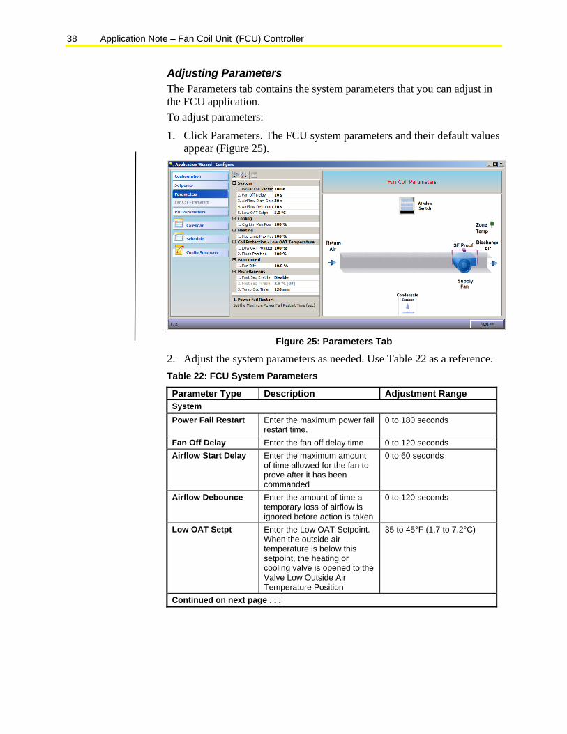
Adjusting Parameters The Parameters tab contains the system parameters that you can adjust in the FCU application. To adjust parameters:
1. Click Parameters. The FCU system parameters and their default values appear (Figure 25).
Figure 25: Parameters Tab
2. Adjust the system parameters as needed. Use Table 22 as a reference. Table 22: FCU System Parameters
Parameter Type Description Adjustment Range System Power Fail Restart Enter the maximum power fail
restart time. 0 to 180 seconds
Fan Off Delay Enter the fan off delay time 0 to 120 seconds Airflow Start Delay Enter the maximum amount
of time allowed for the fan to prove after it has been commanded
0 to 60 seconds
Airflow Debounce Enter the amount of time a temporary loss of airflow is ignored before action is taken
0 to 120 seconds
Low OAT Setpt Enter the Low OAT Setpoint. When the outside air temperature is below this setpoint, the heating or cooling valve is opened to the Valve Low Outside Air Temperature Position
35 to 45°F (1.7 to 7.2°C)
Continued on next page . . .
Application Note – Fan Coil Unit (FCU) Controller 39
Parameter Type (Cont.)
Description Adjustment Range
Cooling Clg Lim Max Pos Enter the cooling limited
maximum position 0 to 100% open
Htg Lim Max Pos Coil Protection-Low OAT
Low OAT Position Enter the valve’s position during Low OAT Shutdown (if enabled)
0 to 100% open
Flush Position Miscellaneous Fan Diff Enter the fan differential 5 to 30% Fast Seq Enable Fast Seq Threshold Enter the amount of
setpoint change needed to switch states during the Fast Sequence mode
0 to 10°F (0 to 5.6°C)
Temp Occ Time Enter the temporary occupancy time
0 to 9,999 seconds
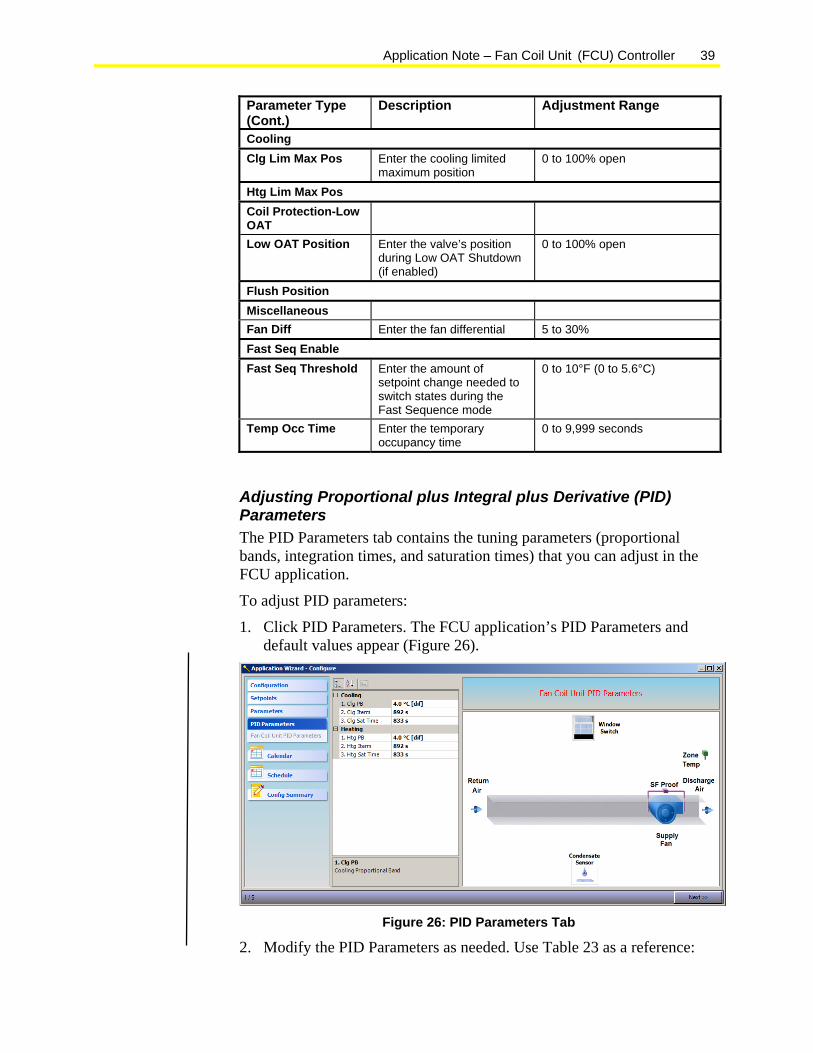
Adjusting Proportional plus Integral plus Derivative (PID) Parameters The PID Parameters tab contains the tuning parameters (proportional bands, integration times, and saturation times) that you can adjust in the FCU application.
To adjust PID parameters:
1. Click PID Parameters. The FCU application’s PID Parameters and default values appear (Figure 26).
Figure 26: PID Parameters Tab
2. Modify the PID Parameters as needed. Use Table 23 as a reference:
40 Application Note – Fan Coil Unit (FCU) Controller
Table 23: FCU PID Parameters
Parameter Type Description Adjustment Range Cooling Clg PB Enter the cooling proportional
band 0 to 100°F (0 to 55.6°C)
Clg Iterm Enter the cooling integration time
0 to 6,553 seconds
Clg Sat Time Enter the cooling saturation time
0 to 6,553 seconds
Heating Htg PB Enter the heating proportional
band 0 to 100°F (0 to 55.6°C)
Htg ITerm Enter the heating integration time
0 to 6,553 seconds
Htg Sat Time Enter the heating saturation time
0 to 6,553 secodns
Configuring the Internal Occupancy Schedule The Schedule and Calendar tabs allow you the ability to configure the internal occupancy schedule.
Note: Using the internal occupancy schedule is optional. You can use an external, network schedule and calendar as an alternative.
To configure the internal occupancy schedule:
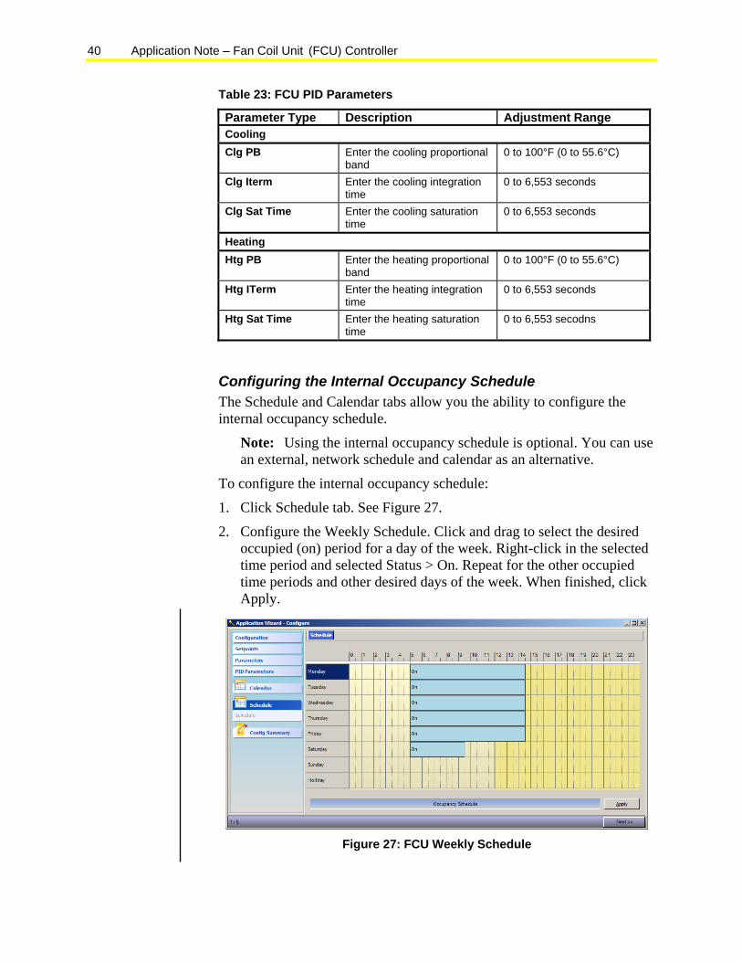
1. Click Schedule tab. See Figure 27.
2. Configure the Weekly Schedule. Click and drag to select the desired occupied (on) period for a day of the week. Right-click in the selected time period and selected Status > On. Repeat for the other occupied time periods and other desired days of the week. When finished, click Apply.
Figure 27: FCU Weekly Schedule
Application Note – Fan Coil Unit (FCU) Controller 41
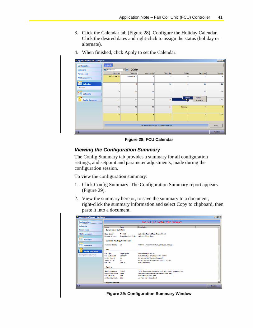
3. Click the Calendar tab (Figure 28). Configure the Holiday Calendar. Click the desired dates and right-click to assign the status (holiday or alternate).
4. When finished, click Apply to set the Calendar.
Figure 28: FCU Calendar
Viewing the Configuration Summary The Config Summary tab provides a summary for all configuration settings, and setpoint and parameter adjustments, made during the configuration session.
To view the configuration summary:
1. Click Config Summary. The Configuration Summary report appears (Figure 29).
2. View the summary here or, to save the summary to a document, right-click the summary information and select Copy to clipboard, then paste it into a document.
Figure 29: Configuration Summary Window
42 Application Note – Fan Coil Unit (FCU) Controller
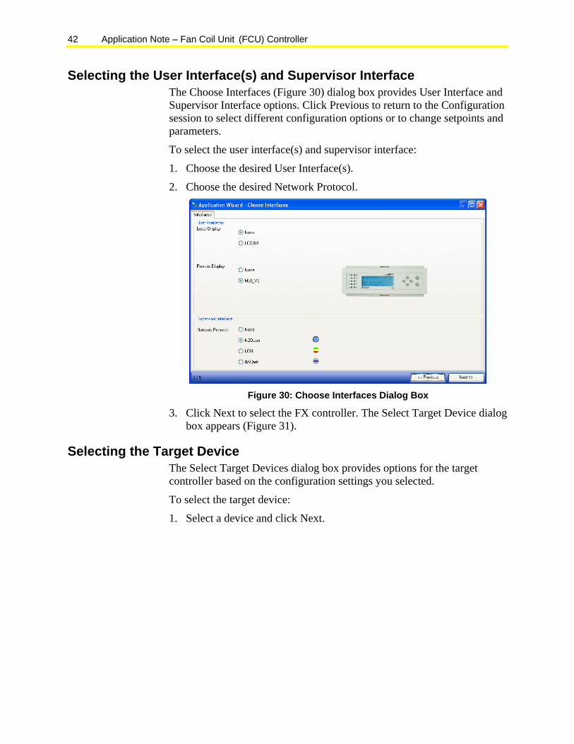
Selecting the User Interface(s) and Supervisor Interface The Choose Interfaces (Figure 30) dialog box provides User Interface and Supervisor Interface options. Click Previous to return to the Configuration session to select different configuration options or to change setpoints and parameters.
To select the user interface(s) and supervisor interface:
1. Choose the desired User Interface(s).
2. Choose the desired Network Protocol.
Figure 30: Choose Interfaces Dialog Box
3. Click Next to select the FX controller. The Select Target Device dialog box appears (Figure 31).
Selecting the Target Device The Select Target Devices dialog box provides options for the target controller based on the configuration settings you selected.
To select the target device:
1. Select a device and click Next.

Application Note – Fan Coil Unit (FCU) Controller 43
Figure 31: Select Target Device Dialog Box - Approved Devices Tab
The Configure Hardware I/O window appears (Figure 33).
Note: If the device you want to use does not appear in the list of approved devices, click the Rejected Devices tab and view the Reason for the rejection (Figure 32). You can also click the Exclusion Details button for more details.
Then, based on the rejection reasons, click Previous to return to the configuration plug-ins and edit the appropriate configuration(s) to configure the device so it is an approved device for the application.
Figure 32: Rejected Devices Tab
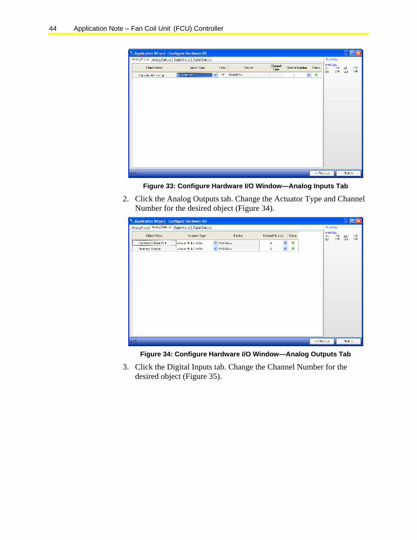
Configuring the Hardware I/Os The Configure Hardware I/O window is organized into tabs based on I/O type (Analog Inputs, Analog Outputs, and Digital Outputs).
To configure the hardware I/Os:
1. Click the Analog Inputs tab. Change the Sensor Type and Channel Number for the desired objects (Figure 33).
44 Application Note – Fan Coil Unit (FCU) Controller
Figure 33: Configure Hardware I/O Window—Analog Inputs Tab
2. Click the Analog Outputs tab. Change the Actuator Type and Channel Number for the desired object (Figure 34).
Figure 34: Configure Hardware I/O Window—Analog Outputs Tab
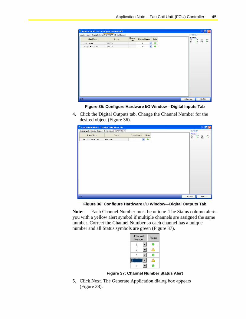
3. Click the Digital Inputs tab. Change the Channel Number for the desired object (Figure 35).
Application Note – Fan Coil Unit (FCU) Controller 45
Figure 35: Configure Hardware I/O Window—Digital Inputs Tab
4. Click the Digital Outputs tab. Change the Channel Number for the desired object (Figure 36).
Figure 36: Configure Hardware I/O Window—Digital Outputs Tab
Note: Each Channel Number must be unique. The Status column alerts you with a yellow alert symbol if multiple channels are assigned the same number. Correct the Channel Number so each channel has a unique number and all Status symbols are green (Figure 37).
Figure 37: Channel Number Status Alert
5. Click Next. The Generate Application dialog box appears (Figure 38).
46 Application Note – Fan Coil Unit (FCU) Controller
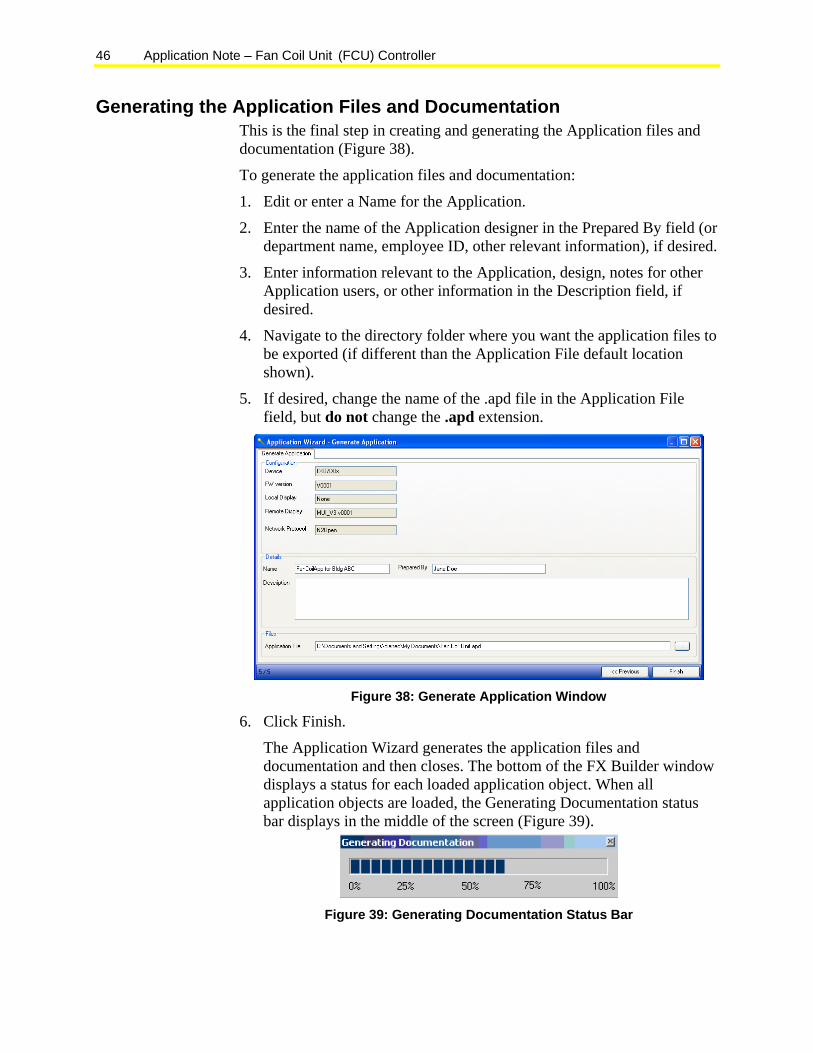
Generating the Application Files and Documentation This is the final step in creating and generating the Application files and documentation (Figure 38).
To generate the application files and documentation:
1. Edit or enter a Name for the Application.
2. Enter the name of the Application designer in the Prepared By field (or department name, employee ID, other relevant information), if desired.
3. Enter information relevant to the Application, design, notes for other Application users, or other information in the Description field, if desired.
4. Navigate to the directory folder where you want the application files to be exported (if different than the Application File default location shown).
5. If desired, change the name of the .apd file in the Application File field, but do not change the .apd extension.
Figure 38: Generate Application Window
6. Click Finish.
The Application Wizard generates the application files and documentation and then closes. The bottom of the FX Builder window displays a status for each loaded application object. When all application objects are loaded, the Generating Documentation status bar displays in the middle of the screen (Figure 39).
Figure 39: Generating Documentation Status Bar
Application Note – Fan Coil Unit (FCU) Controller 47
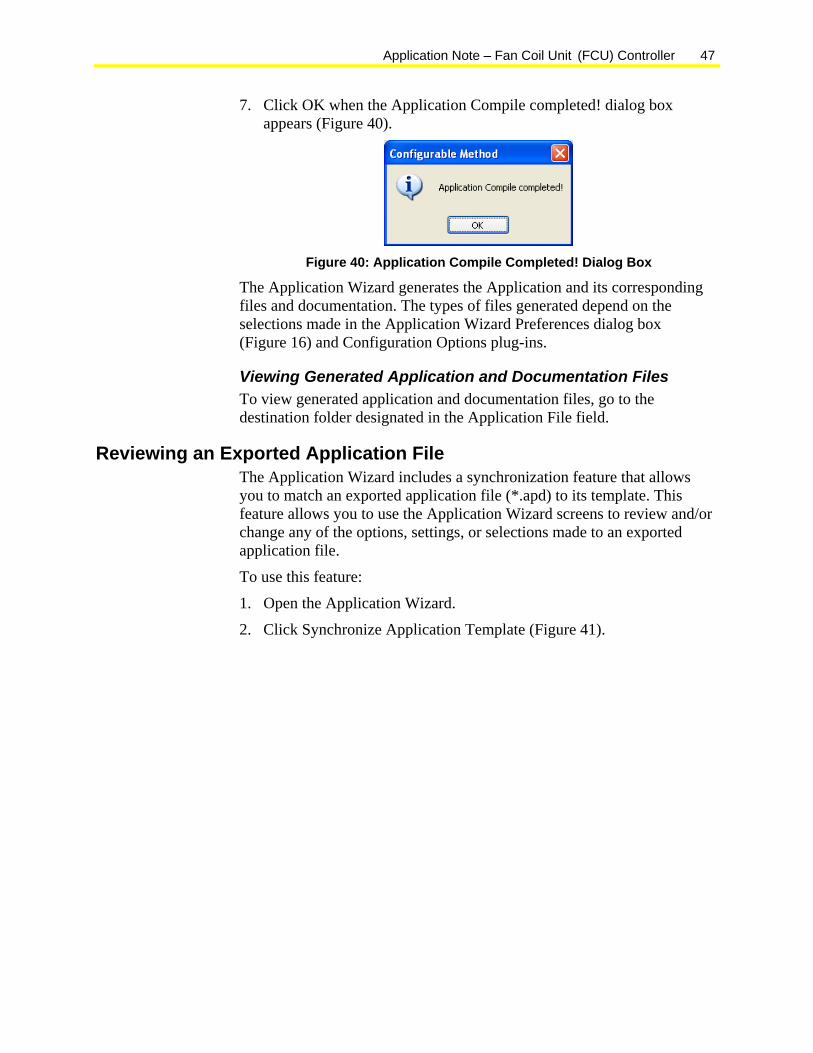
7. Click OK when the Application Compile completed! dialog box appears (Figure 40).
Figure 40: Application Compile Completed! Dialog Box
The Application Wizard generates the Application and its corresponding files and documentation. The types of files generated depend on the selections made in the Application Wizard Preferences dialog box (Figure 16) and Configuration Options plug-ins.
Viewing Generated Application and Documentation Files To view generated application and documentation files, go to the destination folder designated in the Application File field.
Reviewing an Exported Application File The Application Wizard includes a synchronization feature that allows you to match an exported application file (*.apd) to its template. This feature allows you to use the Application Wizard screens to review and/or change any of the options, settings, or selections made to an exported application file.
To use this feature:
1. Open the Application Wizard.
2. Click Synchronize Application Template (Figure 41).

48 Application Note – Fan Coil Unit (FCU) Controller
Figure 41: Synchronize Application Template
The Open Application dialog box appears (Figure 42).
Figure 42: Open Application Dialog Box
3. Navigate to the location of your exported *.apd file, select it and click Open. The Application Wizard reappears, showing if the selected application matches an installed template (Figure 43).

Application Note – Fan Coil Unit (FCU) Controller 49
Figure 43: Application Template Match
4. Click Next. The Application Wizard appears, showing the actual configuration settings, setpoints, adjustment parameters, user interface selection(s), protocol choice, target controller selection, and I/O configurations that were originally made before the application file was exported. You can now use the Application Wizard to view and/or change these settings as desired.
FX CommPro Concepts FX CommPro is a software tool that you use to perform the following functions:
• download the application file to the target controller(s)
• monitor data points
• issue overrides
• adjust unit setpoints and parameters
For detailed information on downloading and commissioning with FX CommPro, refer to the FX CommPro N2 User’s Guide (LIT-12011152) or FX CommPro BACnet User’s Guide (LIT-12011240).
User Interface Concepts The FCU application template supports a choice of two User Interfaces: the Medium User Interface (MUI) and the LCD2x4 User Interface.
50 Application Note – Fan Coil Unit (FCU) Controller
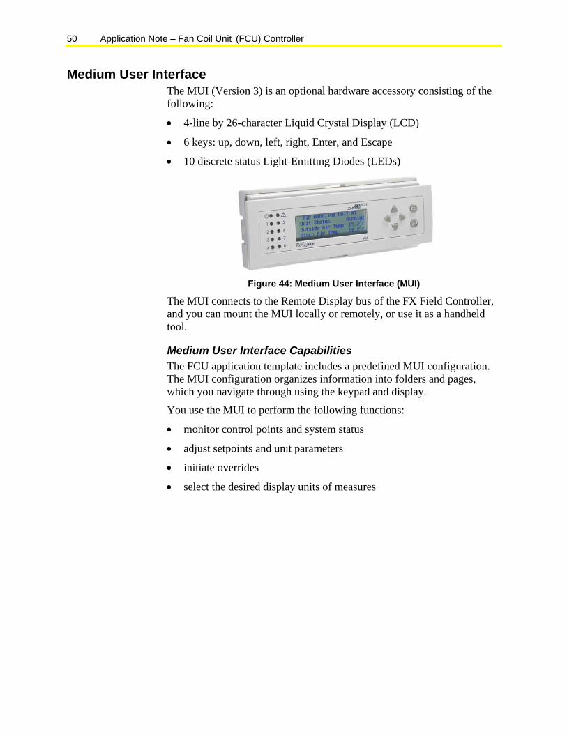
Medium User Interface The MUI (Version 3) is an optional hardware accessory consisting of the following:
• 4-line by 26-character Liquid Crystal Display (LCD)
• 6 keys: up, down, left, right, Enter, and Escape
• 10 discrete status Light-Emitting Diodes (LEDs)
Figure 44: Medium User Interface (MUI)
The MUI connects to the Remote Display bus of the FX Field Controller, and you can mount the MUI locally or remotely, or use it as a handheld tool.
Medium User Interface Capabilities The FCU application template includes a predefined MUI configuration. The MUI configuration organizes information into folders and pages, which you navigate through using the keypad and display.
You use the MUI to perform the following functions:
• monitor control points and system status
• adjust setpoints and unit parameters
• initiate overrides
• select the desired display units of measures
Application Note – Fan Coil Unit (FCU) Controller 51
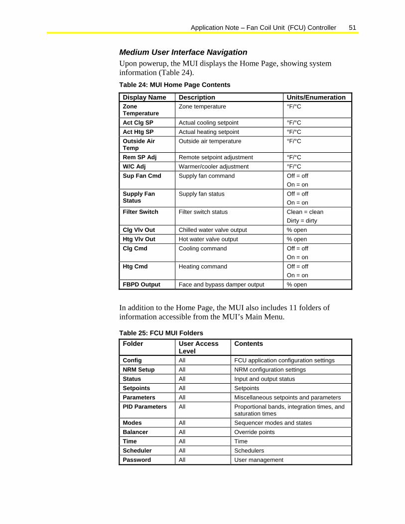
Medium User Interface Navigation Upon powerup, the MUI displays the Home Page, showing system information (Table 24). Table 24: MUI Home Page Contents
Display Name Description Units/Enumeration Zone Temperature
Zone temperature °F/°C
Act Clg SP Actual cooling setpoint °F/°C Act Htg SP Actual heating setpoint °F/°C Outside Air Temp
Outside air temperature °F/°C
Rem SP Adj Remote setpoint adjustment °F/°C W/C Adj Warmer/cooler adjustment °F/°C Sup Fan Cmd Supply fan command Off = off
On = on Supply Fan Status
Supply fan status Off = off On = on
Filter Switch Filter switch status Clean = clean Dirty = dirty
Clg Vlv Out Chilled water valve output % open Htg Vlv Out Hot water valve output % open Clg Cmd Cooling command Off = off
On = on Htg Cmd Heating command Off = off
On = on FBPD Output Face and bypass damper output % open
In addition to the Home Page, the MUI also includes 11 folders of information accessible from the MUI’s Main Menu.
Table 25: FCU MUI Folders Folder User Access
Level Contents
Config All FCU application configuration settings NRM Setup All NRM configuration settings Status All Input and output status Setpoints All Setpoints Parameters All Miscellaneous setpoints and parameters PID Parameters All Proportional bands, integration times, and
saturation times Modes All Sequencer modes and states Balancer All Override points Time All Time Scheduler All Schedulers Password All User management
52 Application Note – Fan Coil Unit (FCU) Controller
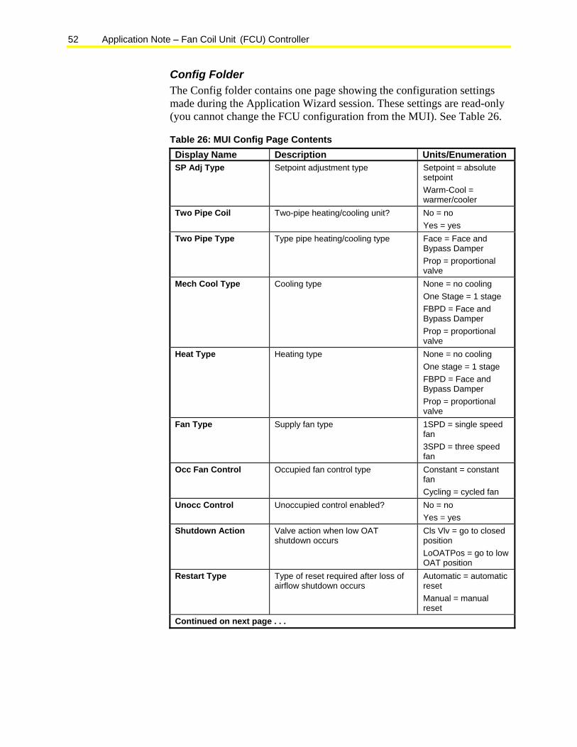
Config Folder The Config folder contains one page showing the configuration settings made during the Application Wizard session. These settings are read-only (you cannot change the FCU configuration from the MUI). See Table 26.
Table 26: MUI Config Page Contents Display Name Description Units/Enumeration SP Adj Type Setpoint adjustment type Setpoint = absolute
setpoint Warm-Cool = warmer/cooler
Two Pipe Coil Two-pipe heating/cooling unit? No = no Yes = yes
Two Pipe Type Type pipe heating/cooling type Face = Face and Bypass Damper Prop = proportional valve
Mech Cool Type Cooling type None = no cooling One Stage = 1 stage FBPD = Face and Bypass Damper Prop = proportional valve
Heat Type Heating type None = no cooling One stage = 1 stage FBPD = Face and Bypass Damper Prop = proportional valve
Fan Type Supply fan type 1SPD = single speed fan 3SPD = three speed fan
Occ Fan Control Occupied fan control type Constant = constant fan Cycling = cycled fan
Unocc Control Unoccupied control enabled? No = no Yes = yes
Shutdown Action Valve action when low OAT shutdown occurs
Cls Vlv = go to closed position LoOATPos = go to low OAT position
Restart Type Type of reset required after loss of airflow shutdown occurs
Automatic = automatic reset Manual = manual reset
Continued on next page . . .
Application Note – Fan Coil Unit (FCU) Controller 53
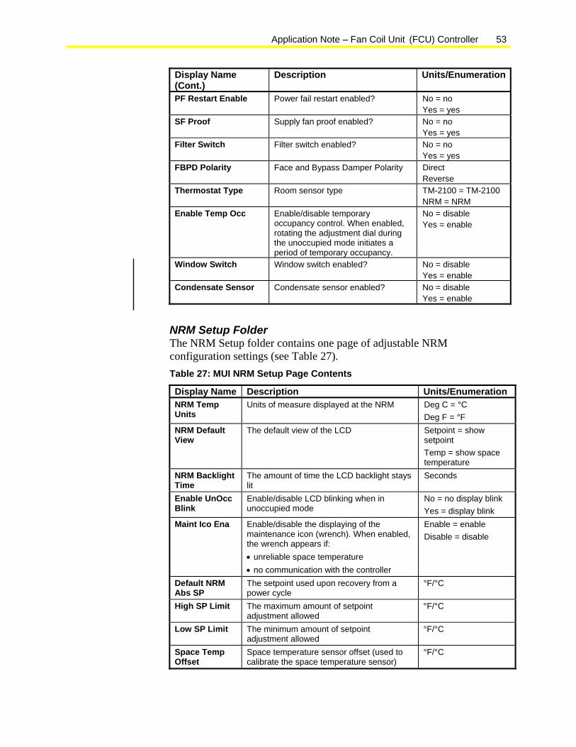
Display Name (Cont.)
Description Units/Enumeration
PF Restart Enable Power fail restart enabled? No = no Yes = yes
SF Proof Supply fan proof enabled? No = no Yes = yes
Filter Switch Filter switch enabled? No = no Yes = yes
FBPD Polarity Face and Bypass Damper Polarity Direct Reverse
Thermostat Type Room sensor type TM-2100 = TM-2100 NRM = NRM
Enable Temp Occ Enable/disable temporary occupancy control. When enabled, rotating the adjustment dial during the unoccupied mode initiates a period of temporary occupancy.
No = disable Yes = enable
Window Switch Window switch enabled? No = disable Yes = enable
Condensate Sensor Condensate sensor enabled? No = disable Yes = enable
NRM Setup Folder The NRM Setup folder contains one page of adjustable NRM configuration settings (see Table 27). Table 27: MUI NRM Setup Page Contents
Display Name Description Units/Enumeration NRM Temp Units
Units of measure displayed at the NRM Deg C = °C Deg F = °F
NRM Default View
The default view of the LCD Setpoint = show setpoint Temp = show space temperature
NRM Backlight Time
The amount of time the LCD backlight stays lit
Seconds
Enable UnOcc Blink
Enable/disable LCD blinking when in unoccupied mode
No = no display blink Yes = display blink
Maint Ico Ena Enable/disable the displaying of the maintenance icon (wrench). When enabled, the wrench appears if: • unreliable space temperature • no communication with the controller
Enable = enable Disable = disable
Default NRM Abs SP
The setpoint used upon recovery from a power cycle
°F/°C
High SP Limit The maximum amount of setpoint adjustment allowed
°F/°C
Low SP Limit The minimum amount of setpoint adjustment allowed
°F/°C
Space Temp Offset
Space temperature sensor offset (used to calibrate the space temperature sensor)
°F/°C
54 Application Note – Fan Coil Unit (FCU) Controller
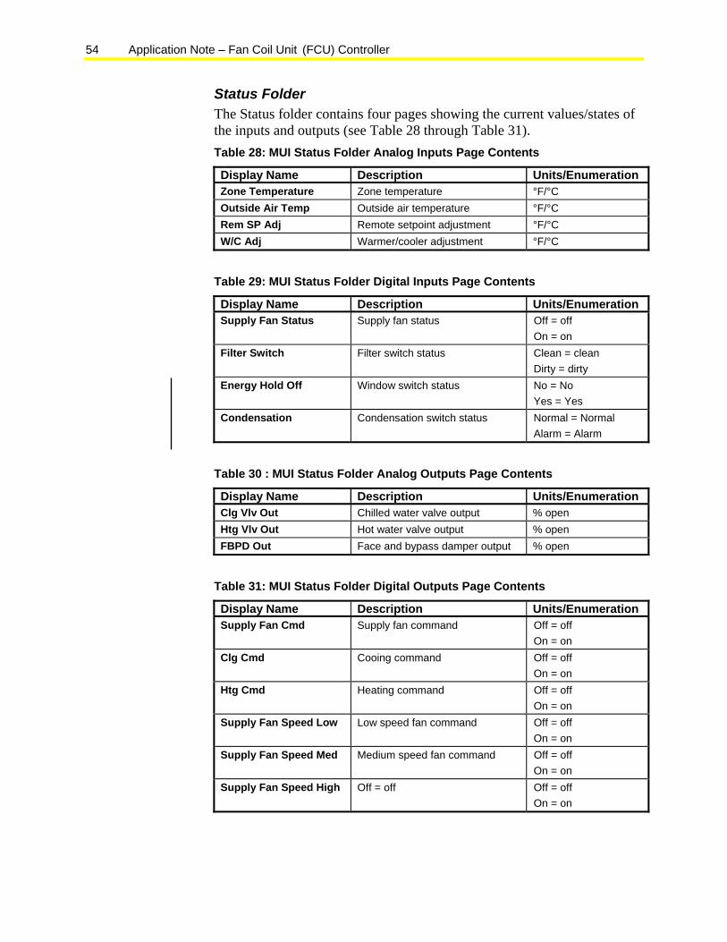
Status Folder The Status folder contains four pages showing the current values/states of the inputs and outputs (see Table 28 through Table 31). Table 28: MUI Status Folder Analog Inputs Page Contents
Display Name Description Units/Enumeration Zone Temperature Zone temperature °F/°C Outside Air Temp Outside air temperature °F/°C Rem SP Adj Remote setpoint adjustment °F/°C W/C Adj Warmer/cooler adjustment °F/°C
Table 29: MUI Status Folder Digital Inputs Page Contents
Display Name Description Units/Enumeration Supply Fan Status Supply fan status Off = off
On = on Filter Switch Filter switch status Clean = clean
Dirty = dirty Energy Hold Off Window switch status No = No
Yes = Yes Condensation Condensation switch status Normal = Normal
Alarm = Alarm
Table 30 : MUI Status Folder Analog Outputs Page Contents
Display Name Description Units/Enumeration Clg Vlv Out Chilled water valve output % open Htg Vlv Out Hot water valve output % open FBPD Out Face and bypass damper output % open
Table 31: MUI Status Folder Digital Outputs Page Contents
Display Name Description Units/Enumeration Supply Fan Cmd Supply fan command Off = off
On = on Clg Cmd Cooing command Off = off
On = on Htg Cmd Heating command Off = off
On = on Supply Fan Speed Low Low speed fan command Off = off
On = on Supply Fan Speed Med Medium speed fan command Off = off
On = on Supply Fan Speed High Off = off Off = off
On = on
Application Note – Fan Coil Unit (FCU) Controller 55
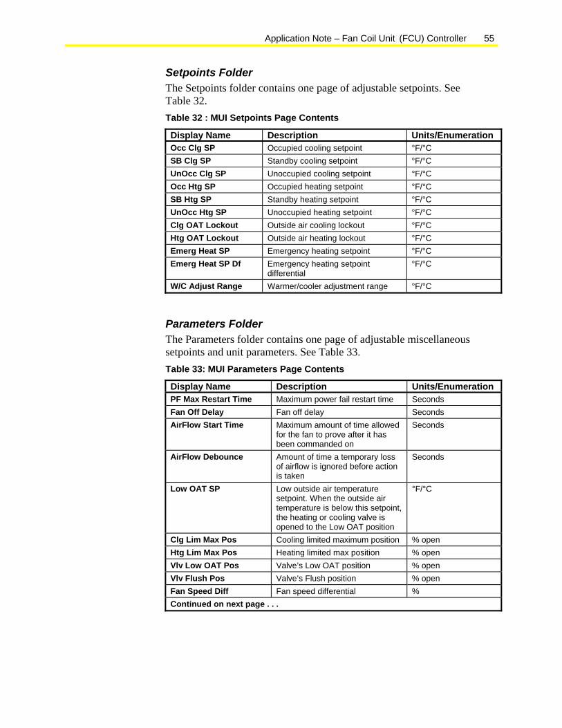
Setpoints Folder The Setpoints folder contains one page of adjustable setpoints. See Table 32. Table 32 : MUI Setpoints Page Contents
Display Name Description Units/Enumeration Occ Clg SP Occupied cooling setpoint °F/°C SB Clg SP Standby cooling setpoint °F/°C UnOcc Clg SP Unoccupied cooling setpoint °F/°C Occ Htg SP Occupied heating setpoint °F/°C SB Htg SP Standby heating setpoint °F/°C UnOcc Htg SP Unoccupied heating setpoint °F/°C Clg OAT Lockout Outside air cooling lockout °F/°C Htg OAT Lockout Outside air heating lockout °F/°C Emerg Heat SP Emergency heating setpoint °F/°C Emerg Heat SP Df Emergency heating setpoint
differential °F/°C
W/C Adjust Range Warmer/cooler adjustment range °F/°C
Parameters Folder The Parameters folder contains one page of adjustable miscellaneous setpoints and unit parameters. See Table 33. Table 33: MUI Parameters Page Contents
Display Name Description Units/Enumeration PF Max Restart Time Maximum power fail restart time Seconds Fan Off Delay Fan off delay Seconds AirFlow Start Time Maximum amount of time allowed
for the fan to prove after it has been commanded on
Seconds
AirFlow Debounce Amount of time a temporary loss of airflow is ignored before action is taken
Seconds
Low OAT SP Low outside air temperature setpoint. When the outside air temperature is below this setpoint, the heating or cooling valve is opened to the Low OAT position
°F/°C
Clg Lim Max Pos Cooling limited maximum position % open Htg Lim Max Pos Heating limited max position % open Vlv Low OAT Pos Valve’s Low OAT position % open Vlv Flush Pos Valve’s Flush position % open Fan Speed Diff Fan speed differential % Continued on next page . . .
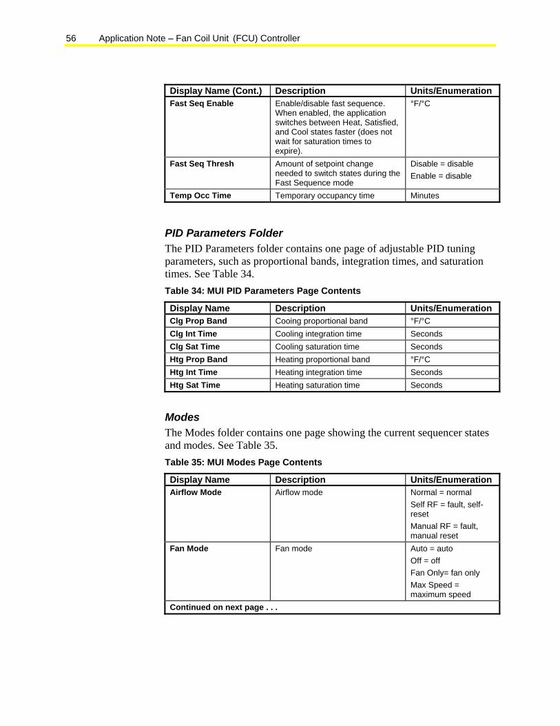
56 Application Note – Fan Coil Unit (FCU) Controller
Display Name (Cont.) Description Units/Enumeration Fast Seq Enable Enable/disable fast sequence.
When enabled, the application switches between Heat, Satisfied, and Cool states faster (does not wait for saturation times to expire).
°F/°C
Fast Seq Thresh Amount of setpoint change needed to switch states during the Fast Sequence mode
Disable = disable Enable = disable
Temp Occ Time Temporary occupancy time Minutes
PID Parameters Folder The PID Parameters folder contains one page of adjustable PID tuning parameters, such as proportional bands, integration times, and saturation times. See Table 34. Table 34: MUI PID Parameters Page Contents
Display Name Description Units/Enumeration Clg Prop Band Cooing proportional band °F/°C Clg Int Time Cooling integration time Seconds Clg Sat Time Cooling saturation time Seconds Htg Prop Band Heating proportional band °F/°C Htg Int Time Heating integration time Seconds Htg Sat Time Heating saturation time Seconds
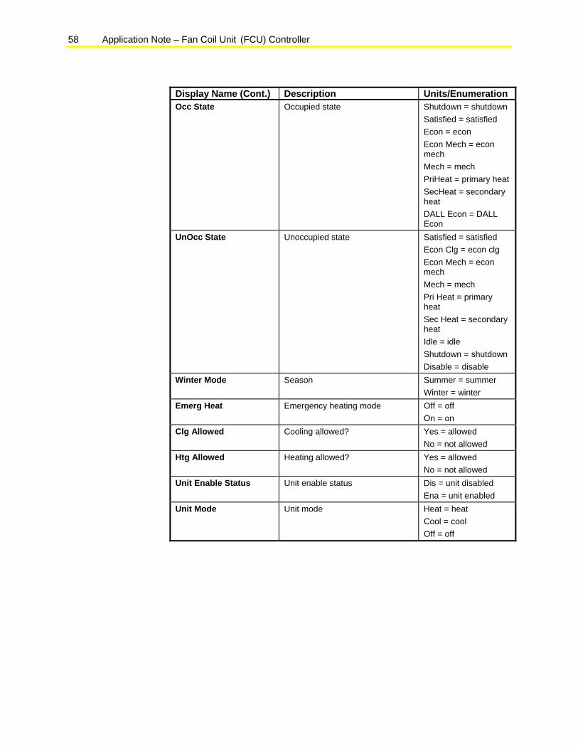
Modes The Modes folder contains one page showing the current sequencer states and modes. See Table 35. Table 35: MUI Modes Page Contents
Display Name Description Units/Enumeration Airflow Mode Airflow mode Normal = normal
Self RF = fault, self-reset Manual RF = fault, manual reset
Fan Mode Fan mode Auto = auto Off = off Fan Only= fan only Max Speed = maximum speed
Continued on next page . . .
Application Note – Fan Coil Unit (FCU) Controller 57
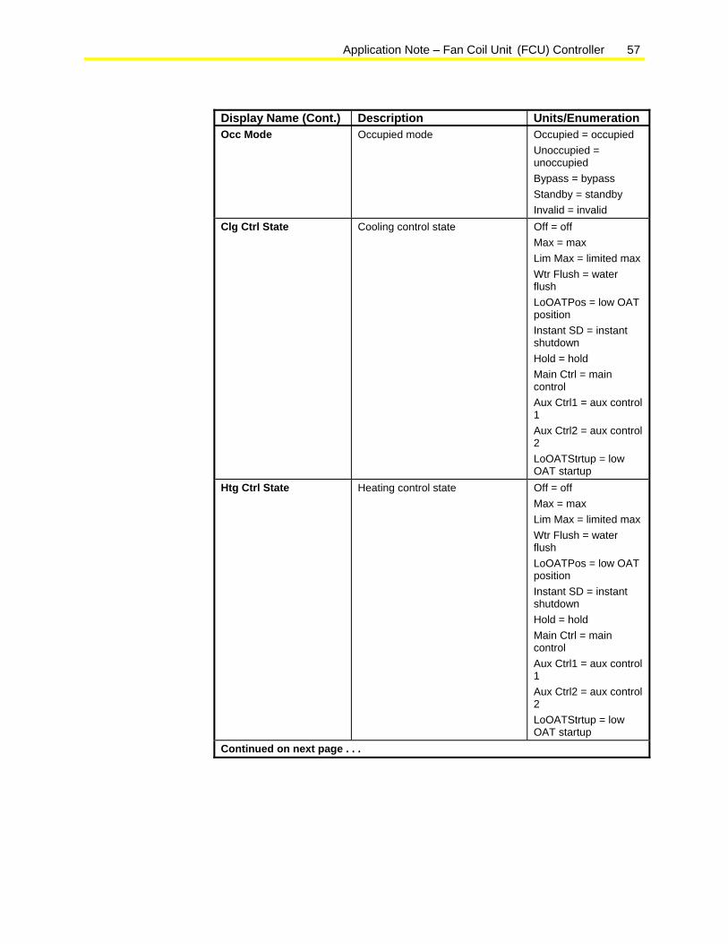
Display Name (Cont.) Description Units/Enumeration Occ Mode Occupied mode Occupied = occupied
Unoccupied = unoccupied Bypass = bypass Standby = standby Invalid = invalid
Clg Ctrl State Cooling control state Off = off Max = max Lim Max = limited max Wtr Flush = water flush LoOATPos = low OAT position Instant SD = instant shutdown Hold = hold Main Ctrl = main control Aux Ctrl1 = aux control 1 Aux Ctrl2 = aux control 2 LoOATStrtup = low OAT startup
Htg Ctrl State Heating control state Off = off Max = max Lim Max = limited max Wtr Flush = water flush LoOATPos = low OAT position Instant SD = instant shutdown Hold = hold Main Ctrl = main control Aux Ctrl1 = aux control 1 Aux Ctrl2 = aux control 2 LoOATStrtup = low OAT startup
Continued on next page . . .
58 Application Note – Fan Coil Unit (FCU) Controller
Display Name (Cont.) Description Units/Enumeration Occ State Occupied state Shutdown = shutdown
Satisfied = satisfied Econ = econ Econ Mech = econ mech Mech = mech PriHeat = primary heat SecHeat = secondary heat DALL Econ = DALL Econ
UnOcc State Unoccupied state Satisfied = satisfied Econ Clg = econ clg Econ Mech = econ mech Mech = mech Pri Heat = primary heat Sec Heat = secondary heat Idle = idle Shutdown = shutdown Disable = disable
Winter Mode Season Summer = summer Winter = winter
Emerg Heat Emergency heating mode Off = off On = on
Clg Allowed Cooling allowed? Yes = allowed No = not allowed
Htg Allowed Heating allowed? Yes = allowed No = not allowed
Unit Enable Status Unit enable status Dis = unit disabled Ena = unit enabled
Unit Mode Unit mode Heat = heat Cool = cool Off = off
Application Note – Fan Coil Unit (FCU) Controller 59
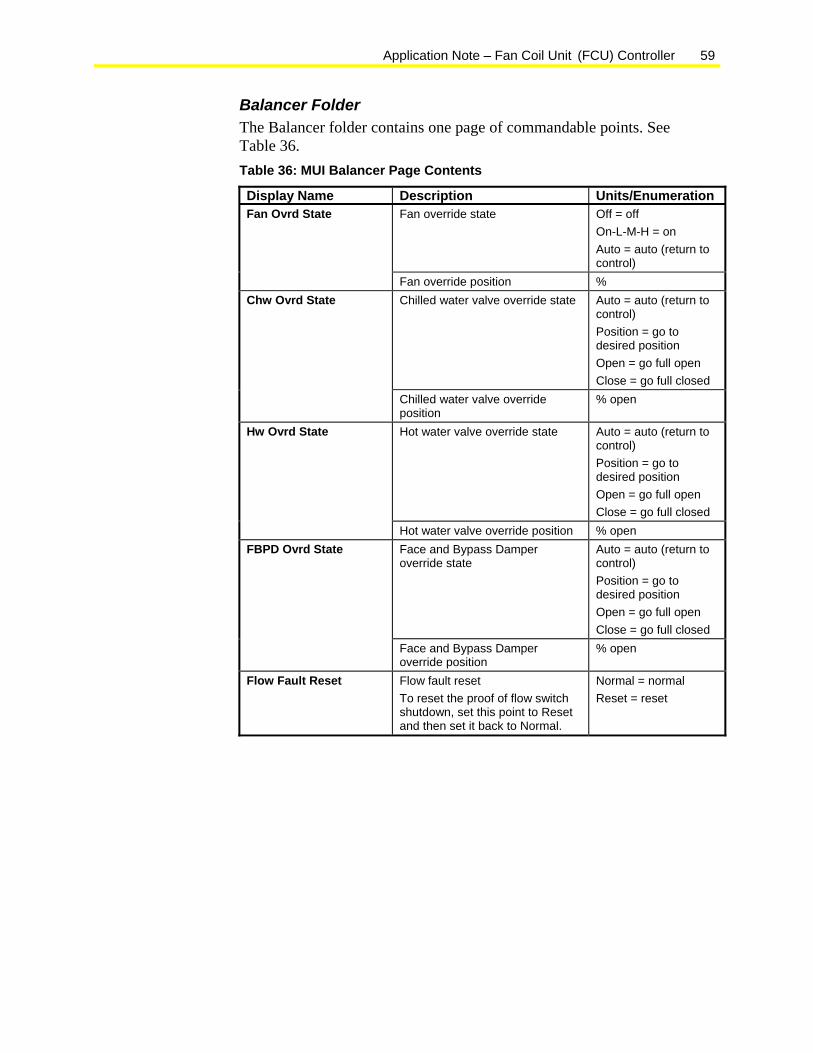
Balancer Folder The Balancer folder contains one page of commandable points. See Table 36. Table 36: MUI Balancer Page Contents
Display Name Description Units/Enumeration Fan override state Off = off
On-L-M-H = on Auto = auto (return to control)
Fan Ovrd State
Fan override position % Chilled water valve override state Auto = auto (return to
control) Position = go to desired position Open = go full open Close = go full closed
Chw Ovrd State
Chilled water valve override position
% open
Hot water valve override state Auto = auto (return to control) Position = go to desired position Open = go full open Close = go full closed
Hw Ovrd State
Hot water valve override position % open Face and Bypass Damper override state
Auto = auto (return to control) Position = go to desired position Open = go full open Close = go full closed
FBPD Ovrd State
Face and Bypass Damper override position
% open
Flow Fault Reset Flow fault reset To reset the proof of flow switch shutdown, set this point to Reset and then set it back to Normal.
Normal = normal Reset = reset
60 Application Note – Fan Coil Unit (FCU) Controller
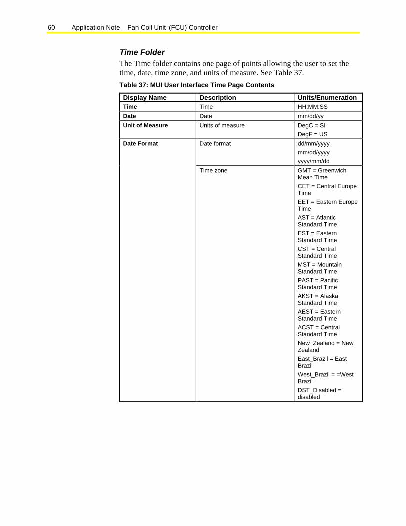
Time Folder The Time folder contains one page of points allowing the user to set the time, date, time zone, and units of measure. See Table 37. Table 37: MUI User Interface Time Page Contents
Display Name Description Units/Enumeration Time Time HH:MM:SS Date Date mm/dd/yy Unit of Measure Units of measure DegC = SI
DegF = US Date format dd/mm/yyyy
mm/dd/yyyy yyyy/mm/dd
Date Format
Time zone GMT = Greenwich Mean Time CET = Central Europe Time EET = Eastern Europe Time AST = Atlantic Standard Time EST = Eastern Standard Time CST = Central Standard Time MST = Mountain Standard Time PAST = Pacific Standard Time AKST = Alaska Standard Time AEST = Eastern Standard Time ACST = Central Standard Time New_Zealand = New Zealand East_Brazil = East Brazil West_Brazil = =West Brazil DST_Disabled = disabled

Application Note – Fan Coil Unit (FCU) Controller 61
Schedulers Folder The Schedulers folder consists of two pages, providing an interface for users to set the local occupancy schedule.
The On Off Schedulers page provides users the ability to assign the occupied (On) and unoccupied (Off) times for Normal and Holiday days.
The Calendar page provides users the ability to identify a specific date as either Normal or Holiday.
Password Folder The Password folder provides user access management for the MUI. Access to all MUI folders is available to all users; therefore, the Password folder feature is not applicable.
MUI Status LEDs None of the MUI’s LEDs are configured to light.
Accessing a Folder in the MUI To access a folder in the MUI:
1. On the Home Page, press the ESC key. The Main Menu appears with folder names.
Each folder contains one or more pages of information. None of the folders are password-protected.
2. Press the up or down arrow keys to select the desired folder.
3. Press the OK key to view the folder contents.
Note: Information displayed on the MUI can include read-only data points as well as writable configuration settings, setpoints, and parameters.
Changing a Configuration Setting, Setpoint, or Parameter in the MUI To change a configuration setting, setpoint, or parameter:
1. Navigate to the page containing the desired point.
2. Press the Enter key to enter the edit mode.
3. Press the up or down arrow to select the desired point.
4. Press the Enter key again.
5. Press the up or down arrow key to toggle the entry to the desired setting or value.
6. Press the Enter key to accept or the Clear key to reject.

62 Application Note – Fan Coil Unit (FCU) Controller
LCD2x4 User Interface The LCD2x4 user interface is an optional hardware accessory consisting of the following:
• 2-line by 4-character LCD
• graphical status icons
• four keys: up, down, clear (C), and OK
The LCD2x4 user interface is available only as an integrated part of the FX06, FX07, and FX14 packaging.
Figure 45: FX07 with Integral LCD2x4 User Interface
LCD2x4 User Interface Capabilities The FCU application template includes a predefined LCD2x4 user interface configuration. The LCD2x4 configuration organizes information into folders and pages which you navigate through using the keypad and display.
You use the LCD2x4 to perform the following functions:
• monitor control points and system status
• adjust setpoints and unit parameters
• initiate overrides
• select the desired display units of measures
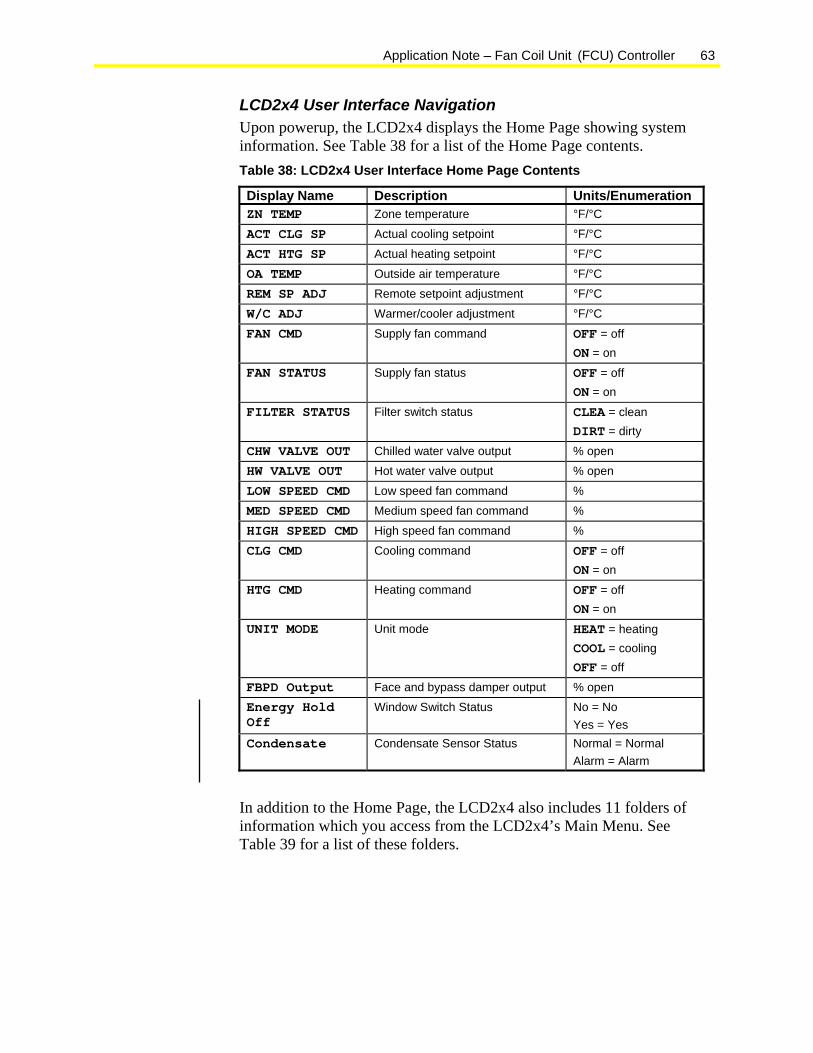
Application Note – Fan Coil Unit (FCU) Controller 63
LCD2x4 User Interface Navigation Upon powerup, the LCD2x4 displays the Home Page showing system information. See Table 38 for a list of the Home Page contents. Table 38: LCD2x4 User Interface Home Page Contents
Display Name Description Units/Enumeration ZN TEMP Zone temperature °F/°C
ACT CLG SP Actual cooling setpoint °F/°C
ACT HTG SP Actual heating setpoint °F/°C
OA TEMP Outside air temperature °F/°C REM SP ADJ Remote setpoint adjustment °F/°C
W/C ADJ Warmer/cooler adjustment °F/°C
FAN CMD Supply fan command OFF = off ON = on
FAN STATUS Supply fan status OFF = off ON = on
FILTER STATUS Filter switch status CLEA = clean DIRT = dirty
CHW VALVE OUT Chilled water valve output % open HW VALVE OUT Hot water valve output % open
LOW SPEED CMD Low speed fan command % MED SPEED CMD Medium speed fan command %
HIGH SPEED CMD High speed fan command %
CLG CMD Cooling command OFF = off ON = on
HTG CMD Heating command OFF = off ON = on
UNIT MODE Unit mode HEAT = heating COOL = cooling OFF = off
FBPD Output Face and bypass damper output % open Energy Hold Off
Window Switch Status No = No Yes = Yes
Condensate Condensate Sensor Status Normal = Normal Alarm = Alarm
In addition to the Home Page, the LCD2x4 also includes 11 folders of information which you access from the LCD2x4’s Main Menu. See Table 39 for a list of these folders.

64 Application Note – Fan Coil Unit (FCU) Controller
Table 39: FCU LCD2x4 Folders Folder User Access
Level Contents
Config Admin FCU application configuration settings NRM Setup All NRM configuration settings FX Setup All LCD2x4 configuration settings Setpoints Admin Setpoints Parameters Admin Miscellaneous setpoints and parameters PID Parameters Admin Proportional bands, integration times, and
saturation times Modes All Sequencer modes and states Balancer Admin Override points Time All Time Scheduler All Schedulers Password All User management
Config Page The Config page is only available to Admin users. The page contains configuration settings made during the Application Wizard session. These settings are read-only (you cannot change the FCU configuration from the LCD2x4). See Table 40. Table 40: LCD2x4 User Interface Config Page Contents
Display Name Description Units/Enumeration SP ADJ TYPE Setpoint adjustment type SETP = absolute setpoint
W/C = warmer/cooler
TWO PIPE COIL Two-pipe heating/cooling unit? NO = no YES = yes
2 PIPE TYPE Type pipe heating/cooling type FACE = face and bypass damper PROP = proportional valve
CLG TYPE Cooling type NONE = No cooling 1STG = 1 stage FBPD = Face and bypass damper PROP = Proportional valve
HTG TYPE Heating type NONE = no cooling 1STG = 1 stage FBPD = face and bypass damper PROP = proportional valve
FAN TYPE Supply fan type 1SPD = single-speed fan 3SPD = three-speed fan
OCC FAN CTRL Occupied fan control type CNST = constant fan CYCL = cycled fan
Continued on next page . . .
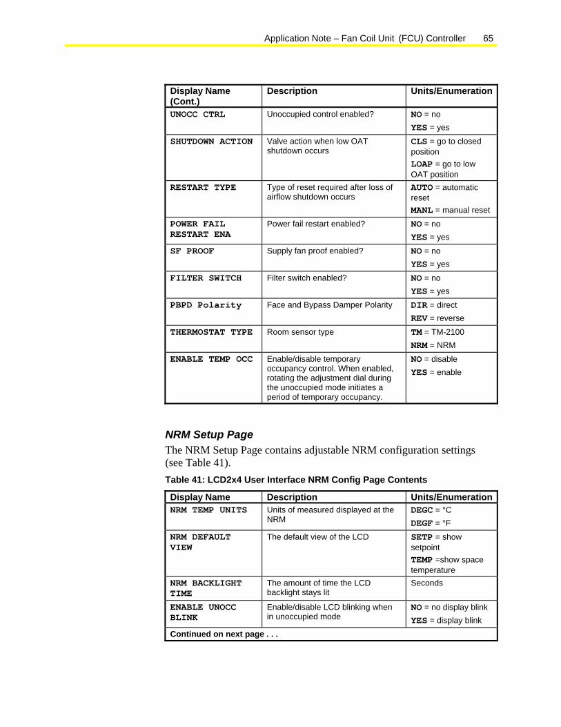
Application Note – Fan Coil Unit (FCU) Controller 65
Display Name (Cont.)
Description Units/Enumeration
UNOCC CTRL Unoccupied control enabled? NO = no YES = yes
SHUTDOWN ACTION Valve action when low OAT shutdown occurs
CLS = go to closed position LOAP = go to low OAT position
RESTART TYPE Type of reset required after loss of airflow shutdown occurs
AUTO = automatic reset MANL = manual reset
POWER FAIL RESTART ENA
Power fail restart enabled? NO = no YES = yes
SF PROOF Supply fan proof enabled? NO = no YES = yes
FILTER SWITCH Filter switch enabled? NO = no YES = yes
PBPD Polarity Face and Bypass Damper Polarity DIR = direct REV = reverse
THERMOSTAT TYPE Room sensor type TM = TM-2100 NRM = NRM
ENABLE TEMP OCC Enable/disable temporary occupancy control. When enabled, rotating the adjustment dial during the unoccupied mode initiates a period of temporary occupancy.
NO = disable YES = enable
NRM Setup Page The NRM Setup Page contains adjustable NRM configuration settings (see Table 41). Table 41: LCD2x4 User Interface NRM Config Page Contents
Display Name Description Units/EnumerationNRM TEMP UNITS Units of measured displayed at the
NRM DEGC = °C DEGF = °F
NRM DEFAULT VIEW
The default view of the LCD SETP = show setpoint TEMP =show space temperature
NRM BACKLIGHT TIME
The amount of time the LCD backlight stays lit
Seconds
ENABLE UNOCC BLINK
Enable/disable LCD blinking when in unoccupied mode
NO = no display blink YES = display blink
Continued on next page . . .
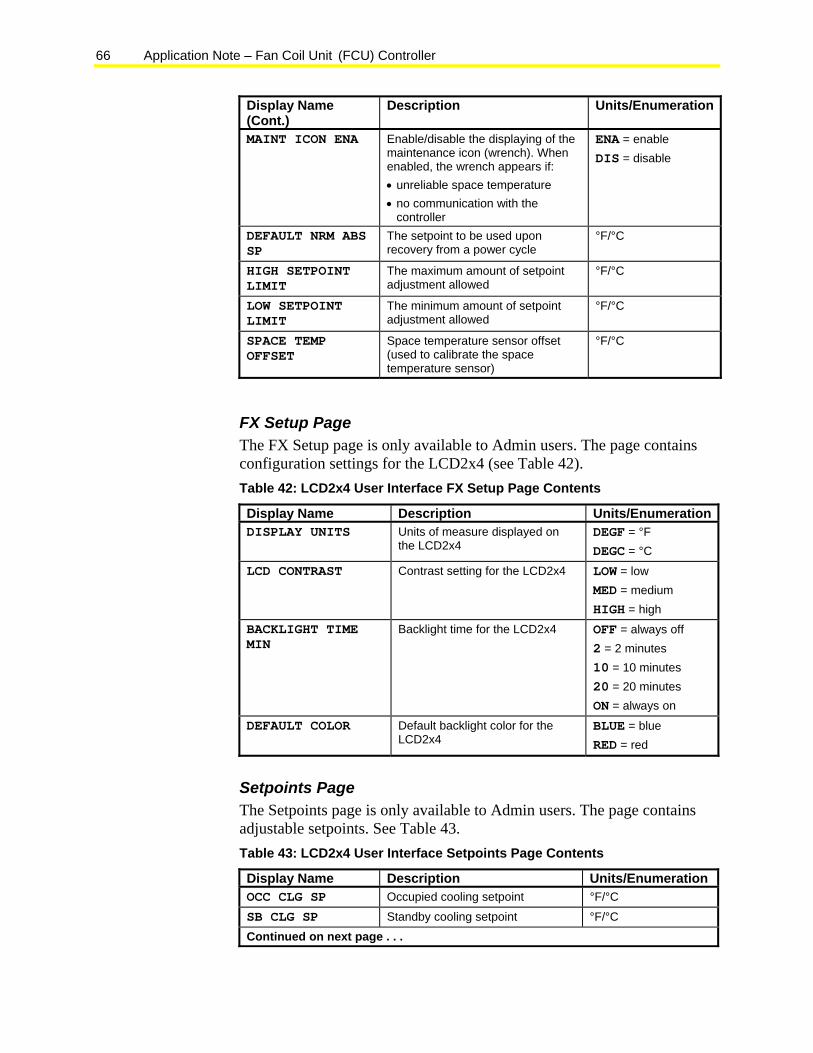
66 Application Note – Fan Coil Unit (FCU) Controller
Display Name (Cont.)
Description Units/Enumeration
MAINT ICON ENA Enable/disable the displaying of the maintenance icon (wrench). When enabled, the wrench appears if: • unreliable space temperature • no communication with the
controller
ENA = enable DIS = disable
DEFAULT NRM ABS SP
The setpoint to be used upon recovery from a power cycle
°F/°C
HIGH SETPOINT LIMIT
The maximum amount of setpoint adjustment allowed
°F/°C
LOW SETPOINT LIMIT
The minimum amount of setpoint adjustment allowed
°F/°C
SPACE TEMP OFFSET
Space temperature sensor offset (used to calibrate the space temperature sensor)
°F/°C
FX Setup Page The FX Setup page is only available to Admin users. The page contains configuration settings for the LCD2x4 (see Table 42). Table 42: LCD2x4 User Interface FX Setup Page Contents
Display Name Description Units/EnumerationDISPLAY UNITS Units of measure displayed on
the LCD2x4 DEGF = °F DEGC = °C
LCD CONTRAST Contrast setting for the LCD2x4 LOW = low MED = medium HIGH = high
BACKLIGHT TIME MIN
Backlight time for the LCD2x4 OFF = always off 2 = 2 minutes 10 = 10 minutes 20 = 20 minutes ON = always on
DEFAULT COLOR Default backlight color for the LCD2x4
BLUE = blue RED = red
Setpoints Page The Setpoints page is only available to Admin users. The page contains adjustable setpoints. See Table 43. Table 43: LCD2x4 User Interface Setpoints Page Contents
Display Name Description Units/Enumeration OCC CLG SP Occupied cooling setpoint °F/°C
SB CLG SP Standby cooling setpoint °F/°C Continued on next page . . .
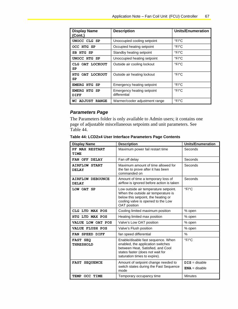
Application Note – Fan Coil Unit (FCU) Controller 67
Display Name (Cont.)
Description Units/Enumeration
UNOCC CLG SP Unoccupied cooling setpoint °F/°C
OCC HTG SP Occupied heating setpoint °F/°C
SB HTG SP Standby heating setpoint °F/°C
UNOCC HTG SP Unoccupied heating setpoint °F/°C CLG OAT LOCKOUT SP
Outside air cooling lockout °F/°C
HTG OAT LOCKOUT SP
Outside air heating lockout °F/°C
EMERG HTG SP Emergency heating setpoint °F/°C EMERG HTG SP DIFF
Emergency heating setpoint differential
°F/°C
WC ADJUST RANGE Warmer/cooler adjustment range °F/°C
Parameters Page The Parameters folder is only available to Admin users; it contains one page of adjustable miscellaneous setpoints and unit parameters. See Table 44. Table 44: LCD2x4 User Interface Parameters Page Contents
Display Name Description Units/Enumeration PF MAX RESTART TIME
Maximum power fail restart time Seconds
FAN OFF DELAY Fan off delay Seconds AIRFLOW START DELAY
Maximum amount of time allowed for the fan to prove after it has been commanded on
Seconds
AIRFLOW DEBOUNCE DELAY
Amount of time a temporary loss of airflow is ignored before action is taken
Seconds
LOW OAT SP Low outside air temperature setpoint. When the outside air temperature is below this setpoint, the heating or cooling valve is opened to the Low OAT position
°F/°C
CLG LTD MAX POS Cooling limited maximum position % open HTG LTD MAX POS Heating limited max position % open
VALUE LOW OAT POS Valve’s Low OAT position % open
VALUE FLUSH POS Valve’s Flush position % open FAN SPEED DIFF fan speed differential % FAST SEQ THRESHOLD
Enable/disable fast sequence. When enabled, the application switches between Heat, Satisfied, and Cool states faster (does not wait for saturation times to expire).
°F/°C
FAST SEQUENCE Amount of setpoint change needed to switch states during the Fast Sequence mode
DIS = disable ENA = disable
TEMP OCC TIME Temporary occupancy time Minutes
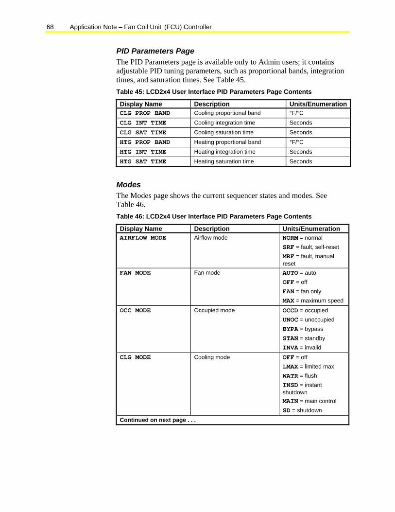
68 Application Note – Fan Coil Unit (FCU) Controller
PID Parameters Page The PID Parameters page is available only to Admin users; it contains adjustable PID tuning parameters, such as proportional bands, integration times, and saturation times. See Table 45. Table 45: LCD2x4 User Interface PID Parameters Page Contents
Display Name Description Units/EnumerationCLG PROP BAND Cooling proportional band °F/°C
CLG INT TIME Cooling integration time Seconds
CLG SAT TIME Cooling saturation time Seconds
HTG PROP BAND Heating proportional band °F/°C HTG INT TIME Heating integration time Seconds
HTG SAT TIME Heating saturation time Seconds
Modes The Modes page shows the current sequencer states and modes. See Table 46. Table 46: LCD2x4 User Interface PID Parameters Page Contents
Display Name Description Units/Enumeration AIRFLOW MODE Airflow mode NORM = normal
SRF = fault, self-reset MRF = fault, manual reset
FAN MODE Fan mode AUTO = auto OFF = off FAN = fan only MAX = maximum speed
OCC MODE Occupied mode OCCD = occupied UNOC = unoccupied BYPA = bypass STAN = standby INVA = invalid
CLG MODE Cooling mode OFF = off LMAX = limited max WATR = flush INSD = instant shutdown MAIN = main control SD = shutdown
Continued on next page . . .
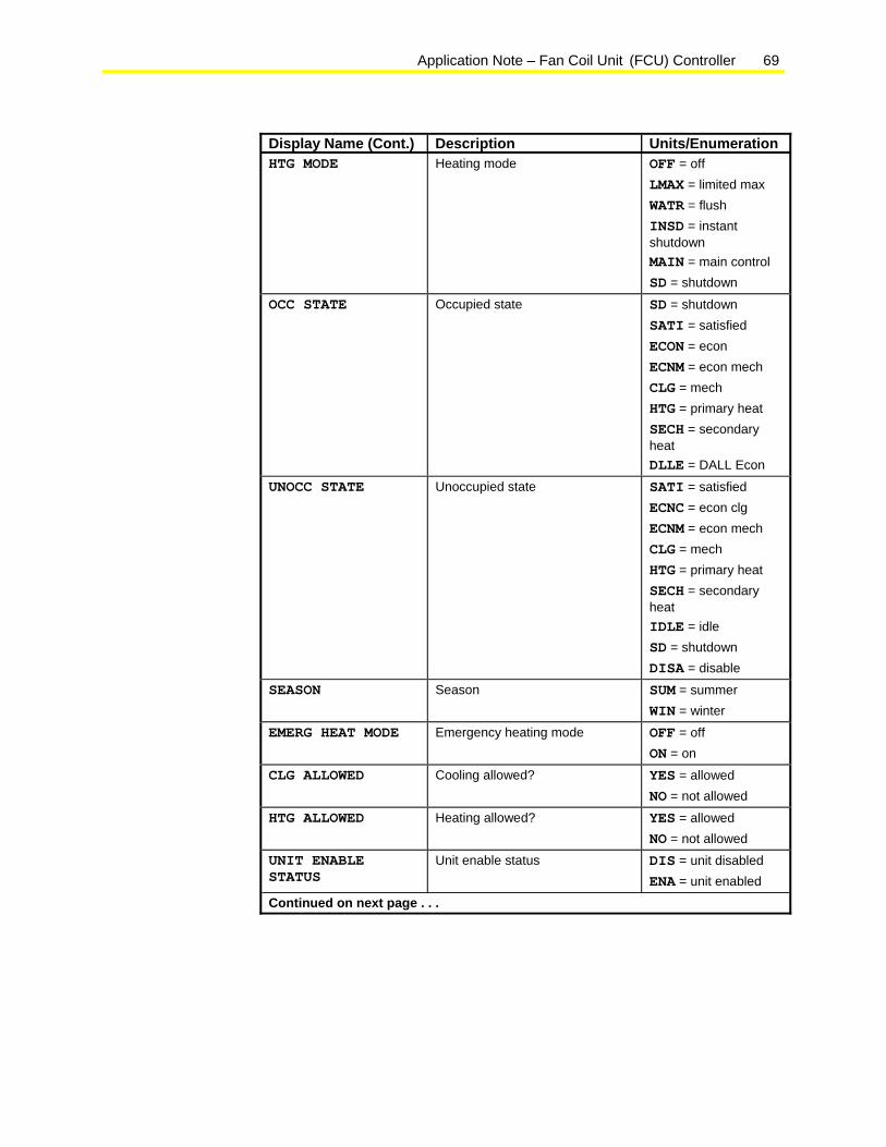
Application Note – Fan Coil Unit (FCU) Controller 69
Display Name (Cont.) Description Units/Enumeration HTG MODE Heating mode OFF = off
LMAX = limited max WATR = flush INSD = instant shutdown MAIN = main control SD = shutdown
OCC STATE Occupied state SD = shutdown SATI = satisfied ECON = econ ECNM = econ mech CLG = mech HTG = primary heat SECH = secondary heat DLLE = DALL Econ
UNOCC STATE Unoccupied state SATI = satisfied ECNC = econ clg ECNM = econ mech CLG = mech HTG = primary heat SECH = secondary heat IDLE = idle SD = shutdown DISA = disable
SEASON Season SUM = summer WIN = winter
EMERG HEAT MODE Emergency heating mode OFF = off ON = on
CLG ALLOWED Cooling allowed? YES = allowed NO = not allowed
HTG ALLOWED Heating allowed? YES = allowed NO = not allowed
UNIT ENABLE STATUS
Unit enable status DIS = unit disabled ENA = unit enabled
Continued on next page . . .
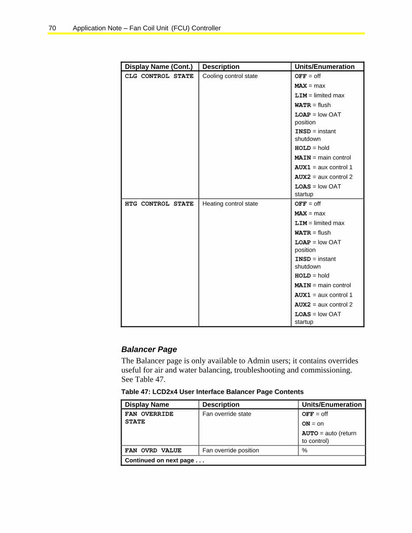
70 Application Note – Fan Coil Unit (FCU) Controller
Display Name (Cont.) Description Units/Enumeration CLG CONTROL STATE Cooling control state OFF = off
MAX = max LIM = limited max WATR = flush LOAP = low OAT position INSD = instant shutdown HOLD = hold MAIN = main control AUX1 = aux control 1 AUX2 = aux control 2 LOAS = low OAT startup
HTG CONTROL STATE Heating control state OFF = off MAX = max LIM = limited max WATR = flush LOAP = low OAT position INSD = instant shutdown HOLD = hold MAIN = main control AUX1 = aux control 1 AUX2 = aux control 2 LOAS = low OAT startup
Balancer Page The Balancer page is only available to Admin users; it contains overrides useful for air and water balancing, troubleshooting and commissioning. See Table 47. Table 47: LCD2x4 User Interface Balancer Page Contents
Display Name Description Units/EnumerationFAN OVERRIDE STATE
Fan override state OFF = off ON = on AUTO = auto (return to control)
FAN OVRD VALUE Fan override position % Continued on next page . . .
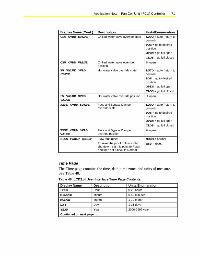
Application Note – Fan Coil Unit (FCU) Controller 71
Display Name (Cont.) Description Units/Enumeration CHW OVRD STATE Chilled water valve override state AUTO = auto (return to
control) POS = go to desired position OPEN = go full open CLOS = go full closed
CHW OVRD VALUE Chilled water valve override position
% open
HW VALUE OVRD STATE
Hot water valve override state AUTO = auto (return to control) POS = go to desired position OPEN = go full open CLOS = go full closed
HW VALUE OVRD VALUE
Hot water valve override position % open
FBPD OVRD STATE Face and Bypass Damper override state
AUTO = auto (return to control) POS = go to desired position OPEN = go full open CLOS = go full closed
FBPD OVRD OVRD VALUE
Face and Bypass Damper override position
% open
FLOW FAULT RESET Flow fault reset To reset the proof of flow switch shutdown, set this point to Reset and then set it back to Normal.
NORM = normal RST = reset
Time Page The Time page contains the time, date, time zone, and units of measure. See Table 48. Table 48: LCD2x4 User Interface Time Page Contents
Display Name Description Units/Enumeration HOUR Hour 0-23 hours
MINUTE Minute 0-59 minutes MONTH Month 1-12 month
DAY Day 1-31 days
YEAR Year 2000-2999 year Continued on next page . . .
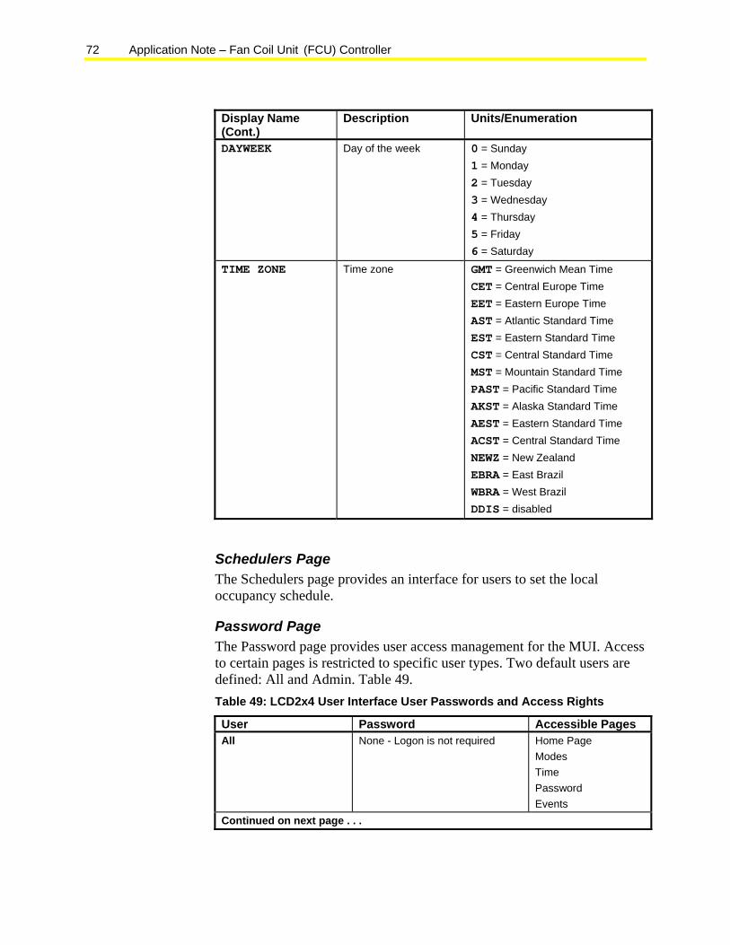
72 Application Note – Fan Coil Unit (FCU) Controller
Display Name (Cont.)
Description Units/Enumeration
DAYWEEK Day of the week 0 = Sunday 1 = Monday 2 = Tuesday 3 = Wednesday 4 = Thursday 5 = Friday 6 = Saturday
TIME ZONE Time zone GMT = Greenwich Mean Time CET = Central Europe Time EET = Eastern Europe Time AST = Atlantic Standard Time EST = Eastern Standard Time CST = Central Standard Time MST = Mountain Standard Time PAST = Pacific Standard Time AKST = Alaska Standard Time AEST = Eastern Standard Time ACST = Central Standard Time NEWZ = New Zealand EBRA = East Brazil WBRA = West Brazil DDIS = disabled
Schedulers Page The Schedulers page provides an interface for users to set the local occupancy schedule.
Password Page The Password page provides user access management for the MUI. Access to certain pages is restricted to specific user types. Two default users are defined: All and Admin. Table 49. Table 49: LCD2x4 User Interface User Passwords and Access Rights
User Password Accessible Pages All None - Logon is not required Home Page
Modes Time Password Events
Continued on next page . . .
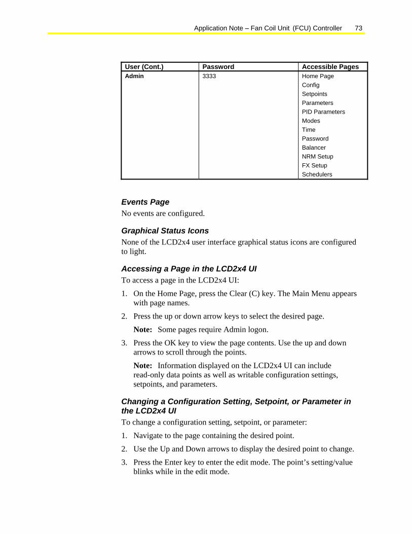
Application Note – Fan Coil Unit (FCU) Controller 73
User (Cont.) Password Accessible Pages Admin 3333 Home Page
Config Setpoints Parameters PID Parameters Modes Time Password Balancer NRM Setup FX Setup Schedulers
Events Page No events are configured.
Graphical Status Icons None of the LCD2x4 user interface graphical status icons are configured to light.
Accessing a Page in the LCD2x4 UI To access a page in the LCD2x4 UI:
1. On the Home Page, press the Clear (C) key. The Main Menu appears with page names.
2. Press the up or down arrow keys to select the desired page.
Note: Some pages require Admin logon.
3. Press the OK key to view the page contents. Use the up and down arrows to scroll through the points.
Note: Information displayed on the LCD2x4 UI can include read-only data points as well as writable configuration settings, setpoints, and parameters.
Changing a Configuration Setting, Setpoint, or Parameter in the LCD2x4 UI To change a configuration setting, setpoint, or parameter:
1. Navigate to the page containing the desired point.
2. Use the Up and Down arrows to display the desired point to change.
3. Press the Enter key to enter the edit mode. The point’s setting/value blinks while in the edit mode.
74 Application Note – Fan Coil Unit (FCU) Controller
4. Press the up or down arrow to toggle the entry to the desired setting or value.
5. Press the Enter key to accept the change or the Clear (C) key to reject the change.
Supervisor Interface The FCU application template contains predefined mappings between the application points and N2 points, LONWORKS® network variables, and BACnet® objects. After you select the protocol type in the Application Wizard, the corresponding network profile is added to the FCU application file.
The actual network profile depends on which configuration settings were selected in the Application Wizard. The Protocol Documentation and Network Resource Files generated by the Application Wizard provide you with details about the actual network profile. Make sure you select the appropriate options in the Application Wizard Preferences dialog box, or the desired files are not generated.
• If the Generate Protocol Documentation option was selected in the Application Wizard Preferences dialog, then the network documentation is generated at the end of the Application Wizard session.
• If the Generate Network Protocol Files option was selected, then the N2 Print files (*.prn) or LONWORKS network resource files (*.xif, *.typ, *.enu, *.ftp, *.typ) are generated at the end of the Application Wizard session.
Note: BACnet integration does not require resource files.
Building Efficiency
507 E. Michigan Street, Milwaukee, WI 53202
Johnson Controls® is a registered trademark of Johnson Controls, Inc. All other marks herein are the marks of their respective owners. © 2009 Johnson Controls, Inc.