Embed Size (px)
Citation preview

James B. Robinson1
Electrochemical Innovation Lab,
Department of Chemical Engineering,
UCL,
London WC1E7JE, UK
e-mail: [email protected]
Donal P. FineganElectrochemical Innovation Lab,
Department of Chemical Engineering,
UCL,
London WC1E 7JE, UK;
National Renewable Energy Laboratory,
15013 Denver West Parkway,
Golden, CO 80401
e-mail: [email protected]
Thomas M. M. HeenanElectrochemical Innovation Lab,
Department of Chemical Engineering,
UCL,
London WC1E7JE, UK
e-mail: [email protected]
Katherine SmithSharp Laboratories of Europe,
Oxford Science Park,
Edmund Halley Road,
Oxford OX4 4GB, Oxfordshire, UK
e-mail: [email protected]
Emma KendrickSharp Laboratories of Europe,
Oxford Science Park,
Edmund Halley Road,
Oxford OX4 4GB, Oxfordshire, UK;
Electrochemical Innovation Lab,
Department of Chemical Engineering,
UCL,
London WC1E 7JE, UK;
Warwick Manufacturing Group,
University Road, University of Warwick,
Coventry CV4 7AL, UK
e-mail: [email protected]
Daniel J. L. BrettElectrochemical Innovation Lab,
Department of Chemical Engineering,
UCL,
London WC1E7JE, UK
e-mail: [email protected]
Paul R. Shearing1
Electrochemical Innovation Lab,
Department of Chemical Engineering,
UCL,
London WC1E7JE, UK
e-mail: [email protected]
Microstructural Analysis of theEffects of Thermal Runaway onLi-Ion and Na-Ion BatteryElectrodesThermal runaway is a phenomenon that occurs due to self-sustaining reactions withinbatteries at elevated temperatures resulting in catastrophic failure. Here, the thermalrunaway process is studied for a Li-ion and Na-ion pouch cells of similar energy density(10.5 Wh, 12 Wh, respectively) using accelerating rate calorimetry (ARC). Both cellswere constructed with a z-fold configuration, with a standard shutdown separator in theLi-ion and a low-cost polypropylene (PP) separator in the Na-ion. Even with the shut-down separator, it is shown that the self-heating rate and rate of thermal runaway inNa-ion cells is significantly slower than that observed in Li-ion systems. The thermal run-away event initiates at a higher temperature in Na-ion cells. The effect of thermal run-away on the architecture of the cells is examined using X-ray microcomputedtomography, and scanning electron microscopy (SEM) is used to examine the failed elec-trodes of both cells. Finally, from examination of the respective electrodes, likely due tothe carbonate solvent containing electrolyte, it is suggested that thermal runaway in Na-ion batteries (NIBs) occurs via a similar mechanism to that reported for Li-ion cells.[DOI: 10.1115/1.4038518]
Introduction
Since their introduction in the early 1990 s, Li-ion batteries(LIB) have become ubiquitous in portable energy storage and
have been employed in increasingly compact and power-intensiveapplications, including automotive power trains [1–3]. While fail-ure rates of Li-ion batteries are estimated to be as low as one in40� 106, a number of high-profile incidents [4–7] have resultedin increased concern regarding LIB cell safety [8]. In addition toconcerns over the safety of Li-ion cells, the relatively high cost ofthe cells [9] and potential volatility in Li supply chains [10] haveled to increased interest in developing new battery chemistries.
1Corresponding author.Manuscript received July 20, 2017; final manuscript received October 4, 2017;
published online December 6, 2017. Assoc. Editor: Matthew Mench.
Journal of Electrochemical Energy Conversion and Storage FEBRUARY 2018, Vol. 15 / 011010-1Copyright VC 2018 by ASME; use license CC-BY 4.0
Downloaded From: http://electrochemical.asmedigitalcollection.asme.org/ on 01/04/2018 Terms of Use: http://www.asme.org/about-asme/terms-of-use

Despite the now widespread use of Li-ion cells, recent workhas seen an increased focus on developing and commercializingalternative battery types for a range of applications. Ni-basedcells, such as the NiCd and NiMH, have both been widely used;however, these cells suffer from a low cell potential (1.2 V) incomparison with Li-ion cells (typically around 3.8 V) [11] andalso have both a higher internal resistance and lower cycle lifethan comparable Li-ion systems [12]. Na-based cells have alsoseen commercialization through the so-called ZEBRA cell, ahigh-temperature molten salt battery which has a more favorableopen-circuit potential of 2.58 V than Ni cells. This battery hasbeen shown to be reliable through extensive in-field testing [13];however, the high-temperature operation restricts the applicationof such a cell to stationary or automotive applications. Solid Nametal-based cells, such as the Na-S cell, have also beenresearched and used in the field although these cells have beenfound to suffer from dendrite growth under room temperatureoperation, which has resulted in severe safety concerns [14]. Simi-lar issues have also been reported in Zn-air batteries [15] whichhave the advantage of higher specific energy densities than Li-ionsystems [16], in addition to favorable economic costs [17].
One of the most promising battery types in development is theNa-ion battery (NIB), which uses a Na-based positive electrodewhich has the benefits of low-cost and global abundance in compar-ison with the Li compounds used in Li-ion systems [18]. In additionto the economic benefits associated with the charge carrier, theoverall cost of the cell can also be reduced by removing the neces-sity for a copper current collector at the negative electrode as, incontrast to Li, Na does not alloy with aluminum [19]. This configu-ration also offers potential benefits in terms of safe storage andtransport of batteries; once discharges NIB can be stored at zerovolts in shorted state, as the aluminum does not dissolve into theelectrolyte at low voltages and reprecipitate upon charge [20]. Thisoffers the potential for shipping and storage of cells which containno energy. Na-ion research has, to date, largely focused on obtain-ing and optimizing electrode materials with a large number of can-didates for both positive and negative electrode materials beinginvestigated. Hard carbon materials which have a reversiblecapacity of ca. 300 mAh g�1 [21] have typically been used as thenegative electrode material due to the low cost of the precursorsand ease of production, while this capacity is similar to that of a Li-ion cell (theoretical capacity of 372 mAh g�1); hard carbon electro-des suffer from a poor first cycle Faradaic efficiency and capacityfades over multiple cycles [22]. Despite the widespread use of hardcarbon, a range of other materials including metal oxides such asSb2O4 have exhibited reversible capacities approaching 900 mAhg�1 [23] while the intermetallic compound SnSb/C was shown byXiao et al. to have a capacity of 435 mAh g�1 and Faradaic effi-ciency in excess of 98% after 50 cycles [24].
Positive electrode materials for Na-ion cells have typicallyfocused on structures capable of housing Naþ ions rather thanusing metallic Na (as negative electrodes within cells) as theselayered oxide materials can avoid dendritic growth at the elec-trode surface [25,26]. Recent developments in positive electrodematerials are summarized by Xiang et al. [27] with theoreticalcapacities ranging from ca. 100–250 mAh g�1 comparable toLIB. This results in a necessity to have a higher mass loading ofthe positive electrode in comparison with even a standard hardcarbon negative electrode. While Na-ion batteries currently lagbehind Li-ion systems in terms of volumetric energy and powerdensity in applications where this is not a large concern, forinstance grid scale power storage, this cell may offer a viablealternative in the near future for applications where cost andsafety are the key drivers. This can be seen by the recent integra-tion of a Na-ion cell into an e-bike and the significant increase inacademic interest in recent times as highlighted by Vignaroobanet al. [28]. In conjunction with the research being conducted onimproved materials, it is imperative to understand the failure proc-esses which occur in Na-ion cells in order to expedite commerci-alization opportunities.
Research into the thermal [8,29–31], electrochemical [32–34],and failure mechanisms [35–37] in Li-ion systems are widespread;however, at present similar studies of Na-ion cells are scarce, par-ticularly at the cell level. Recent work performed by Xia andDahn has examined the safety of positive electrode materials forNa-ion cells showing that NaCrO2 is a less reactive positive elec-trode material than LiFePO4 in similar nonaqueous electrolytes[38]. Here, a combination of accelerating rate calorimetry (ARC)and postmortem materials characterization is used to examine thethermal failure properties of a Na-ion cell compared with a com-mercially available Li-ion cell. This technique has previouslybeen used to study the failure mechanisms and characteristics of arange of Li-ion chemistries [39–41], examining the effect of tem-perature on electrolyte degradation and the thermal stability ofelectrode materials. ARC is a procedure that is used for the mea-surement of the heat expelled from a material during self-heating.The “heat-wait-search” protocol enables the identification of keythermal steps in the failure of cells, for instance, as described inthis work, the onset temperature of thermal runaway in cells. Theperformance of Na-ion cells is also benchmarked against a similarcommercially available LiCoO2 battery. Pre- and postmortemanalysis of the cells is also performed in order to highlight thechange in both cell and electrode architectures which in turn mayhave an influence on the safety of multicell packs.
Experimental
Accelerating rate calorimetry experiments were performed ontwo pouch cells of similar energy density and form factor. The Na-ion cell (NIB) used in this work is based on a layered oxide positiveelectrode material and hard carbon negative electrode materialdeveloped by Sharp Laboratories of Europe (90� 75� 7 mm, SLE,Oxford, UK), with a polypropylene separator, mixed carbonate sol-vent (EC:DEC), 1M NaPF6 salt [42] and a capacity of 12 Wh(3000 mAh). The LIB cell (85� 45� 8 mm, AA Portable PowerCorp., Richmond, CA) which had a capacity of 10.5 Wh (2500mAh) is based on a LiCoO2 (LCO) positive and graphite (negative)electrode material, with a tri-layer (shutdown) separator, and thecomposition of the electrolyte is EC:DMC with �1M LiPF6. Priorto conducting the ARC experiments, the NIB was fully charged to4 V (the maximum rated voltage) at 1C, via a constant-current,constant-voltage charging protocol. The LCO cell commercialpouch cell was charged using the same protocol to 4.2 V. The cellswere allowed to equilibrate, and the open circuit potential wasmeasured directly prior to the thermal runaway experiment toensure no capacity fade occurred.
Prior to the failure of each cell X-ray computed tomography(CT), images of both cells in their fresh, fully charged state were
Fig. 1 NIB cell suspended on wires in the calorimeter, alsoshown are the location of the thermocouples used for the ARCexperiment on the front and rear of the cell
011010-2 / Vol. 15, FEBRUARY 2018 Transactions of the ASME
Downloaded From: http://electrochemical.asmedigitalcollection.asme.org/ on 01/04/2018 Terms of Use: http://www.asme.org/about-asme/terms-of-use

captured using a Nikon XT 225 machine. The geometric configu-ration of the radiographic scans resulted in a pixel resolution ofbetween 59 and 65 lm. In all cases, an accelerating voltage of210 kV with a tungsten target was used to generate 3176 projec-tions of the cells. The radiographic dataset acquired was recon-structed using a filtered back projection algorithm built into thecommercially available CT PRO 3D software with subsequent visu-alization achieved using AVIZO FIRE 9.2 (FEI Company, Hillsboro,OR).
Accelerating rate calorimetry was performed inside a calorime-ter (Phitec Battery Test Calorimeter, HEL Group, Hertfordshire,UK) using the heat-wait-search method. This is a standard methodthat involves heating the sample to the start temperature, follow-ing which a period is observed for the environmental temperatureto stabilize followed by the measurement of any self-heating. Forboth cells, self-heating rates in excess of 0.02 �C min�1 weretracked until the heating stopped. Once the self-heating had fin-ished, the set temperature was raised by 5 �C and the processrepeated until thermal runaway occurred: in order to ensure safeoperation, a maximum temperature of 280 �C was set in bothinstances. Temperature change was monitored using two K-typethermocouple which were placed in similar locations on opposingsides of the cell, as shown in Fig. 1. The cell was then suspendedin the center of the calorimeter (see Fig. 1) to ensure radiativeeffects were accounted for. After thermal runaway, the calorime-ter was left to cool to ambient temperature before postmortem X-ray CT of the failed cells was performed using the Nikon XT 225instrument. In all cases, an accelerating voltage of 200 kV wasused with the power subsequently optimized to provide sufficientcounts of 60,000 on the detector.
Pre- and postmortem scanning electron microscope (SEM)images were obtained using a Zeiss EVO 10 SEM (Carl ZeissAG, Germany) with imaging being performed at 10 kV using thesecondary electron (SE1) signal to obtain images of the NIB celland at 15 kV using the same SE1 signal to obtain images of theLi-ion cells before and after failure. Magnifications of approxi-mately 10,000� were obtained resulting in a pixel size of 29 nmin all cases. The fresh samples were prepared in a glovebox beforelater being transferred, in a sealed container, to the SEM minimiz-ing air and moisture exposure.
Results and Discussion
Accelerating rate calorimetry was performed in order to inducethermal runaway in both NIB and LCO cells. The temperatureprofiles obtained for both types of cell are shown in Fig. 2. Theinitial plateaus observed for NIB and LCO cells before the initialexothermic event are thought to be the initial breakdown of thesolid electrolyte interphase (SEI). It is observed that the time
before the first exotherm is significantly longer in the LCO cellcompared to the NIB. In both cases, an initial exotherm is seen toinitiate between 30 and 50 �C; this initial temperature rise has pre-viously been suggested to be as a result of the breakdown and sub-sequent reformation of the SEI layer in Li-ion batteries [43]. Thehigher temperature exotherm for LCO cells compared to NIB andthe longer time taken to reach this first exothermic event are likelydue to the stability of the SEI layer; with the SEI in Li-ion bat-teries being more stable to higher temperatures. Sodium salts arein general more stable than lithium salts, and therefore it is notunreasonable to assume that the SEI in NIB is significantly moresoluble than LIB. The earlier onset temperature and shorter timeto reach this first exothermic event in NIB suggests that it isimportant to consider the SEI formation further. To our knowl-edge, formation studies have not yet been performed for NIB, norelectrolyte additives investigated, and this result highlights theneed for more detailed studies to stabilize and understand NIBSEI further. Once this initial exotherm has concluded, a secondexotherm is visible which indicates the onset of thermal runaway.This is seen in the profiles shown in Fig. 2 with thermal runawayapparent due to a sudden increase in the temperature of the cellwith the region highlighted. A difference between the cells is seenwith a second plateau region visible in the temperature trace ofthe LCO cell; this may be attributed to the presence of a so-called“shutdown separator” in the LCO cell which is not incorporated inthe NIB cell. These shutdown separators are composite structuresconsisting of a tri-layer of polypropylene (PP), polyethylene (PE),and polypropylene (PP|PE|PP) designed to delay or indeed preventthermal runaway in the case of electrical abuse [44,45]. It is alsopossible that within this temperature window, the LCO cell rup-tured, resulting in the Joule–Thompson effect occurring—aneffect which has previously been observed in 18,650 type Li-ioncells [36]. Despite the integration of safety devices such as theshutdown separator, thermal runaway will only be delayed duringARC due to the temperature increasing until failure.
To evaluate the respective thermal runaway process, the self-heating rate of both cells during the ARC experiment was calcu-lated; these results are outlined in Fig. 3 with a clear discontinuityin the LCO cell visible, once again most likely due to the ruptureof the LCO cell. It is shown in Fig. 3 that the self-heating rate forthe NIB cell is significantly lower at the initial stages of theexperiment (corresponding to the blue line). In this region, ther-mal runaway has not yet occurred in either cell. As the energydensity is similar between both cells, this suggests the initial deg-radation and decomposition of the components of LCO cells asso-ciated with elevated temperatures are mildly less exothermic thanthose observed in NIB systems; however, the thermal runawayevent is significantly more exothermic in the LCO cell than theNIB battery.
Fig. 2 SEM images of (a) pristine, and (b) failed, negative electrodes from the LCO cell, (c) pristine LiCoO2 posi-tive electrode, (d) LiCoO2 positive electrode after thermal runaway has occurred. All images are obtained usingthe SE1 signal at 15 kV accelerating voltage with magnifications of approximately 10,000 yielding a pixel size of29 nm in all cases.
Journal of Electrochemical Energy Conversion and Storage FEBRUARY 2018, Vol. 15 / 011010-3
Downloaded From: http://electrochemical.asmedigitalcollection.asme.org/ on 01/04/2018 Terms of Use: http://www.asme.org/about-asme/terms-of-use

The rate of change of temperature after the onset of thermalrunaway occurs within the cells also shows a stark difference. Thediscontinuity provided by the shutdown separator prior to thermalrunaway is once again visible for the LCO cell in Fig. 3(b) withthe self-heating rates occurring during the initial stages of thermalrunaway also highlighted with a red line. Due to the rapid natureof thermal runaway and the upper safety limit imposed on theARC experiment, it was not possible to capture the self-heatingrate to the conclusion of the cell failure. Despite this, it is evidentfrom Fig. 3 that the thermal runaway reaction is significantlyfaster over the temperature range in a LCO cell; with the larger
Fig. 3 SEM images of (a) pristine, and (b) failed, negative electrodes from the LCO cell, (c) pristine LiCoO2 posi-tive electrode, (d) LiCoO2 positive electrode after thermal runaway has occurred. All images are obtained usingthe SE1 signal at 15 kV accelerating voltage with magnifications of approximately 10,000 yielding a pixel size of29 nm in all cases.
Table 1 Rate of reactions of the isotherms observed in Fig. 3corresponding to the initial degradation of the cell (blue, asseen in Fig. 3) and thermal runaway (red, as seen in Fig. 3)
Reaction rate(min�1)
Initial degradation(blue)
Thermal runaway(red)
NIB 9.92� 10�3 5.68� 10�2
LCO 7.65� 10�3 2.13� 10�1
Fig. 4 Cell scale tomographic renderings of the charged ((a)–(c)) and failed ((d)–(f)) NIB celland the charged ((g)–(i)) and failed LCO ((j)–(l)) showing the extent of deformation associatedwith thermal runaway
011010-4 / Vol. 15, FEBRUARY 2018 Transactions of the ASME
Downloaded From: http://electrochemical.asmedigitalcollection.asme.org/ on 01/04/2018 Terms of Use: http://www.asme.org/about-asme/terms-of-use
gradient visible in the self-heating rate of the LCO cell indicativeof a higher reaction rate as shown in Table 1.
This increased reaction rate reduces the time frame for the heatto dissipate and consequently would result in a faster temperaturerise when incorporated into a pack or module. In turn, this sug-gests that NIB cells fail with less risk of cell-to-cell propagationof thermal runaway and therefore may be a safer option in situa-tions where concerns over thermal runaway exceed the require-ment for the comparably higher volumetric/gravimetric powerdensities provided by Li-ion cells. It must also be noted that theLCO cells used in these experiments are not considered the mostunstable [31] and cells with cathodic materials such as nickelmanganese cobalt or nickel cobalt aluminum oxide, which arewidely used in electric vehicles and will exhibit even greater ratesof heat generation during thermal runaway as a result of the moreexothermic decompositions of the respective positive electrodes.
X-ray CT was performed on the charged NIB and LCO cellsboth before and after ARC: this nondestructive technique enablesthe full visualization of the architectural changes that occur withinthe cells due to the thermal runaway event. Full three-dimensionalrenderings of the respective cells are shown both prior to and afterthe failure of batteries in Fig. 4. The current collecting tabs arelocated on different edges of the respective cells and the orthogo-nal planes are in view for comparison, i.e., the front view is the(x, y) plane, and the side view (x, z) and the underside view arethe (y, z) plane. These images show the significant alterations inboth the internal and external structures as a result of the thermalrunaway.
It is clear from Fig. 4 that thermal runaway has a catastrophiceffect on the external housing of both cells. Ruptures are visible atthe current collecting tabs for both batteries (Figs. 4(d) and 4(l))while an additional rupture is also seen to occur in the side of theNIB cell (Fig. 4(e)). These differences may be due to a variationof the quality of the seal achieved in each cell with the commer-cial LCO cell being subjected to a more rigorous quality controlprocedure than the NIB cell which was produced in a small batch.In order to quantify the extent of the deformation caused by ther-mal runaway, dimensional measurements were taken along themajor orthogonal axes of the individual cells before and after fail-ure as outlined in Table 2.
It is clear from Table 2 that the NIB cell suffers more severedistortion than the LCO cell during thermal runaway. This may bedue to a variation in the sealing strategy of the cells; however, inthis instance, it is important to stress that while a single cell whichexperiences such expansion changes may be acceptable, shouldmultiple cells be combined together in a pack this could lead toheightened stress on the module. In all cases, it is seen that somechanges to the cell structure occur; however, for both the LCOand NIB cells, the largest of these deviations occur due to gasespassing through the cell toward the seal along which the currentcollecting tabs protrude. While this is useful in order to removepotentially toxic gases from the module, it may be useful toemploy a small pressure relief component in the cells to mitigateagainst the large architectural distortions in cells and reduce themechanical stress on components within a battery pack, such as istypically observed in spiral wound cell geometries. It should be
noted that the NIB cells used in this work were produced in smallbatches; as such, further optimization of the electrolyte may resultin reduced gas generation further improving the safety of thecells.
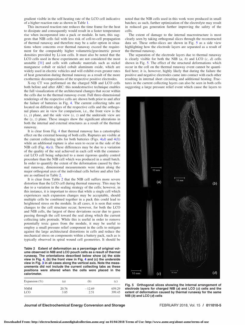
The extent of damage to the internal macrostructure is mostclearly seen by taking orthogonal slices through the reconstructeddata set. These ortho-slices are shown in Fig. 5 as a side viewhighlighting how the electrode layers are separated as a result ofthe thermal runaway.
The separation of the electrode layers due to thermal runawayis clearly visible for both the NIB (a, b) and LCO (c, d) cellsshown in Fig. 5. The effect of the structural deformations whichoccur in the cell on the thermal runaway event cannot be quanti-fied here; it is, however, highly likely that during the failure thepositive and negative electrodes came into contact with each otherresulting in internal short circuiting and additional heating. Frac-tures in the current collecting layers can also be seen in both cellssuggesting a large pressure relief event which cause the layers to
Table 2 Extent of deformation as a percentage of original vol-ume observed in NIB and LCO pouch cells as a result of thermalrunaway. The orientations described below show (a) the sideview in Fig. 4, (b) the front view in Fig. 4 and (c) the undersideview in Fig. 3 in all cases along the vertical axis. Note the meas-urements did not include the current collecting tabs as thesepositions were altered when the cells were placed in thecalorimeter.
Expansion (%) (a) (b) (c)
NMM 20.76 �12.69 659.29LCO 3.85 2.51 399.45
Fig. 5 Orthogonal slices showing the internal arrangement ofelectrode layers for charged NIB (a) and LCO (c) cells and theextent of deformation caused by thermal runaway for the sameNIB (b) and LCO (d) cells
Journal of Electrochemical Energy Conversion and Storage FEBRUARY 2018, Vol. 15 / 011010-5
Downloaded From: http://electrochemical.asmedigitalcollection.asme.org/ on 01/04/2018 Terms of Use: http://www.asme.org/about-asme/terms-of-use
fracture, similar to effects previously reported by Finegan et al.[35]. Additionally, the electrode stack is seen to rise from the baseof the pack in the NIB cell which contributes to the larger expan-sion in this plane, noted in Table 2.
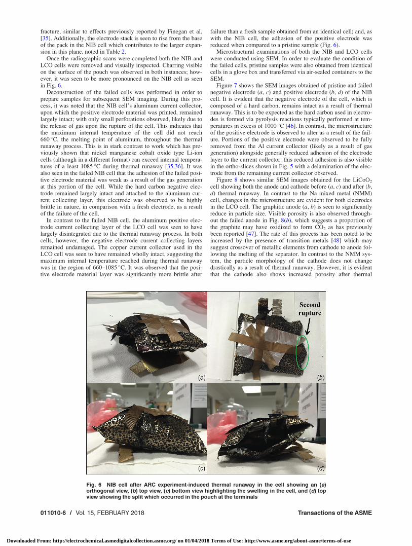
Once the radiographic scans were completed both the NIB andLCO cells were removed and visually inspected. Charring visibleon the surface of the pouch was observed in both instances; how-ever, it was seen to be more pronounced on the NIB cell as seenin Fig. 6.
Deconstruction of the failed cells was performed in order toprepare samples for subsequent SEM imaging. During this pro-cess, it was noted that the NIB cell’s aluminum current collector,upon which the positive electrode material was printed, remainedlargely intact; with only small perforations observed, likely due tothe release of gas upon the rupture of the cell. This indicates thatthe maximum internal temperature of the cell did not reach660 �C, the melting point of aluminum, throughout the thermalrunaway process. This is in stark contrast to work which has pre-viously shown that nickel manganese cobalt oxide type Li-ioncells (although in a different format) can exceed internal tempera-tures of a least 1085 �C during thermal runaway [35,36]. It wasalso seen in the failed NIB cell that the adhesion of the failed posi-tive electrode material was weak as a result of the gas generationat this portion of the cell. While the hard carbon negative elec-trode remained largely intact and attached to the aluminum cur-rent collecting layer, this electrode was observed to be highlybrittle in nature, in comparison with a fresh electrode, as a resultof the failure of the cell.
In contrast to the failed NIB cell, the aluminum positive elec-trode current collecting layer of the LCO cell was seen to havelargely disintegrated due to the thermal runaway process. In bothcells, however, the negative electrode current collecting layersremained undamaged. The copper current collector used in theLCO cell was seen to have remained wholly intact, suggesting themaximum internal temperature reached during thermal runawaywas in the region of 660–1085 �C. It was observed that the posi-tive electrode material layer was significantly more brittle after
failure than a fresh sample obtained from an identical cell; and, aswith the NIB cell, the adhesion of the positive electrode wasreduced when compared to a pristine sample (Fig. 6).
Microstructural examinations of both the NIB and LCO cellswere conducted using SEM. In order to evaluate the condition ofthe failed cells, pristine samples were also obtained from identicalcells in a glove box and transferred via air-sealed containers to theSEM.
Figure 7 shows the SEM images obtained of pristine and failednegative electrode (a, c) and positive electrode (b, d) of the NIBcell. It is evident that the negative electrode of the cell, which iscomposed of a hard carbon, remains intact as a result of thermalrunaway. This is to be expected as the hard carbon used in electro-des is formed via pyrolysis reactions typically performed at tem-peratures in excess of 1000 �C [46]. In contrast, the microstructureof the positive electrode is observed to alter as a result of the fail-ure. Portions of the positive electrode were observed to be fullyremoved from the Al current collector (likely as a result of gasgeneration) alongside generally reduced adhesion of the electrodelayer to the current collector: this reduced adhesion is also visiblein the ortho-slices shown in Fig. 5 with a delamination of the elec-trode from the remaining current collector observed.
Figure 8 shows similar SEM images obtained for the LiCoO2
cell showing both the anode and cathode before (a, c) and after (b,d) thermal runaway. In contrast to the Na mixed metal (NMM)cell, changes in the microstructure are evident for both electrodesin the LCO cell. The graphitic anode (a, b) is seen to significantlyreduce in particle size. Visible porosity is also observed through-out the failed anode in Fig. 8(b), which suggests a proportion ofthe graphite may have oxidized to form CO2 as has previouslybeen reported [47]. The rate of this process has been noted to beincreased by the presence of transition metals [48] which maysuggest crossover of metallic elements from cathode to anode fol-lowing the melting of the separator. In contrast to the NMM sys-tem, the particle morphology of the cathode does not changedrastically as a result of thermal runaway. However, it is evidentthat the cathode also shows increased porosity after thermal
Fig. 6 NIB cell after ARC experiment-induced thermal runaway in the cell showing an (a)orthogonal view, (b) top view, (c) bottom view highlighting the swelling in the cell, and (d) topview showing the split which occurred in the pouch at the terminals
011010-6 / Vol. 15, FEBRUARY 2018 Transactions of the ASME
Downloaded From: http://electrochemical.asmedigitalcollection.asme.org/ on 01/04/2018 Terms of Use: http://www.asme.org/about-asme/terms-of-use

runaway has occurred; once more, this is likely due to gas genera-tion at the cathode layer as a result of an interaction between thecathode and electrolyte. As with the NMM system, this gas gener-ation has resulted in portions of the cathode being removed fromthe current collector with large areas of bare current collector visi-ble in Fig. 8. The generation of gas due to thermal runaway haspreviously been reported by Golubkov et al. [31] who showed thatthe gases generated are typically a mix of alkanes, alkenes, andhydrogen, the ratios of which depend on the cathode chemistryemployed. The SEM images shown in Fig. 7 suggest that thermalrunaway reactions in NIB cells occur via a similar mechanism tothat reported in Li-ion systems. Maleki et al. [40] suggested thatthermal runaway in LCO/graphite systems (as used in this study)is initiated by the heat generated via the breakdown of the positiveelectrode and subsequent reaction with the electrolyte. The NIBcells in this study similarly show electrode degradation at the pos-itive electrode, suggesting that it is also this layer which plays thelargest part in the reactions which lead to thermal runaway.
Conclusions
Accelerating rate calorimetry experiments comparing NIB con-taining a layered oxide positive electrode and commercial LIBcontaining LiCoO2 positive electrode have shown highlightedsome important differences. NIB appears to have a shorter time tothe first exothermic event that also occurs at a slightly lower tem-perature than LIB, while the rate of thermal runaway exhibited byNa-ion cells is lower than that observed in (LCO) cells. A shut-down separator present in the LCO cells significantly delays the
time taken to reach the onset of thermal runaway; however, itdoes not prevent thermal runaway in this case, which is compara-ble to the conditions experienced during a fire. This indicates thatthe solubility of the SEI layer in NIB is likely to be much greaterthan LIB, occurring in shorter time frames and at lower tempera-tures. However, the initial repeated dissolving and reforming ofthis SEI (as indicated by self-heating rates) observed in the bat-tery, associated with elevated temperatures, is observed to belower in NIB cells, suggesting this is a more stable cell both attemperatures below thermal runaway and during the thermal run-away process itself. The reduced degradation rate provided by theslower reaction kinetics may provide an opportunity to design asystem to isolate or eject the cell in packs or modules.
Examination of the packs by X-ray CT shows significant distor-tions in the architecture of the cell packaging material in both instan-ces. These are more significant in the NIB case which is ascribed tothe sealing strategy of the cell. Such effects may be improved byoptimization of the electrolyte, potentially using less volatile sol-vents. The distortions observed here are likely to induce mechanicalstress within battery packs, which when coupled with the heatingcaused by a cell undergoing thermal runaway, may result in damageto and indeed the failure of neighboring cells, which must beaddressed through adequate safety devices and quality control.
The internal architectures are destroyed in both cells, with theNIB showing a greater disparity from the original orientation ofthe layers. Despite this, the Al current collectors were seen to belargely intact on both electrodes in the NIB cell during postmor-tem analysis, which indicates the temperature reached during ther-mal runaway could not have exceeded 660 �C. In contrast, only
Fig. 7 SEM images of (a) pristine, and (b) failed, negative electrodes from the LCO cell, (c) pristine LiCoO2 positive electrode,(d) LiCoO2 positive electrode after thermal runaway has occurred. All images are obtained using the SE1 signal at 15 kV accel-erating voltage with magnifications of approximately 10,000 yielding a pixel size of 29 nm in all cases.
Journal of Electrochemical Energy Conversion and Storage FEBRUARY 2018, Vol. 15 / 011010-7
Downloaded From: http://electrochemical.asmedigitalcollection.asme.org/ on 01/04/2018 Terms of Use: http://www.asme.org/about-asme/terms-of-use

the Cu current collector in the LCO cell remained intact; there-fore, the maximum temperature reached during thermal runawaymust be in the window 660 �C< Tmax< 1085 �C.
Scanning electron microscope shows significant changes in themicrostructure of both the positive and negative electrodes of theLCO cell after thermal runaway; however, the negative electrode ofthe NIB cell retains a similar microstructure to that observed in apristine cell anode. This suggests that the interaction between thepositive electrode and the decomposed electrolyte is the major causeof thermal runaway, implying thermal runaway occurs in NIB cellsvia similar mechanisms to those reported for Li-ion systems.
Acknowledgment
The authors would like to acknowledge the EPSRC funding forsupporting the work of Robinson through the UCL Doctoral Fel-lowship scheme (EP/M507970/1) and the EPSRC for supportingthe energy storage work in the Electrochemical Innovation Lab(EP/N032888/1; EP/N001583/1; EP/P009050/1; EP/M009394/1).The authors also acknowledge the STFC for supporting Shearingand Brett (ST/K00171X/1) and Royal Academy of Engineeringfor supporting Shearing, and Sharp Laboratories of Europe Ltd.,for the NIB prototype cells.
Funding Data
� Engineering and Physical Sciences Research Council (UCLDoctoral Prize).
References[1] Armand, M., and Tarascon, J.-M., 2008, “Building Better Batteries,” Nature,
451(7179), pp. 652–657.[2] Lu, L., Han, X., Li, J., Hua, J., and Ouyang, M., 2013, “A Review on the Key
Issues for Lithium-Ion Battery Management in Electric Vehicles,” J. PowerSources, 226, pp. 272–288.
[3] Scrosati, B., Hassoun, J., and Sun, Y.-K., 2011, “Lithium-Ion Batteries. A LookInto the Future,” Energy Environ. Sci., 4(9), pp. 3287–3295.
[4] Beauregard, G. P., 2008, “Report of Investigation: Hybrids Plus Plug in HybridElectric Vehicle,” U.S. Department of Energy, Idaho National Laboratory,Idaho Falls, ID, Report No. 5903.
[5] JTSB, 2014, “Aircraft Serious Incident Investigation Report,” All Nippon Air-ways Co., Ltd., Tokyo, Japan, Report No. JA804A.
[6] AAIB, 2015, “Report on the Serious Incident to Boeing B787-8, ET-AOP Lon-don Heathrow Airport on 12 July 2013,” Ethiopian Airlines, Addis Ababa,Ethiopia, Report No. EW/C2013/07/01.
[7] NTSB, 2014, “Aircraft Incident Report, Auxiliary Power Unit Battery Fire,Japan Airlines Boeing 787-8, JA829J,” National Transportation Safety Board,Washington, DC, Report No. NTSB/AIR-14/01.
[8] Robinson, J. B., Darr, J. A., Eastwood, D. S., Hinds, G., Lee, P. D., Shearing, P.R., Taiwo, O. O., and Brett, D. J. L., 2014, “Non-Uniform Temperature Distri-bution in Li-Ion Batteries During Discharge—A Combined Thermal Imaging,X-ray Micro-Tomography and Electrochemical Impedance Approach,” J.Power Sources, 252, pp. 51–57.
[9] Ellis, B. L., Makahnouk, W. R. M., Rowan-Weetaluktuk, W. N., Ryan, D. H.,and Nazar, L. F., 2010, “Crystal Structure and Electrochemical Properties ofA2MPO4F Fluorophosphates (A¼Na, Li; M¼ Fe, Mn, Co, Ni),” Chem. Mater.,22(3), pp. 1059–1070.
[10] U.S. Geological Survey, 2008, “Mineral Commodity Summaries 2008,” U.S.Geological Survey, Reston, VA.
[11] Yang, Y., Hu, X., Qing, D., and Chen, F., 2013, “Arrhenius Equation-BasedCell-Health Assessment: Application to Thermal Energy Management Designof a HEV NiMH Battery Pack,” Energies, 6(5), p. 2709.
[12] Khateeb, S. A., Farid, M. M., Selman, J. R., and Al-Hallaj, S., 2004, “Designand Simulation of a Lithium-Ion Battery With a Phase Change Material
Fig. 8 SEM images of (a) pristine, and (b) failed, negative electrodes from the LCO cell, (c) pristine LiCoO2 positive electrode,(d) LiCoO2 positive electrode after thermal runaway has occurred. All images are obtained using the SE1 signal at 15 kV accel-erating voltage with magnifications of approximately 10,000 yielding a pixel size of 29 nm in all cases.
011010-8 / Vol. 15, FEBRUARY 2018 Transactions of the ASME
Downloaded From: http://electrochemical.asmedigitalcollection.asme.org/ on 01/04/2018 Terms of Use: http://www.asme.org/about-asme/terms-of-use

Thermal Management System for an Electric Scooter,” J. Power Sources,128(2), pp. 292–307.
[13] Galloway, R. C., and Haslam, S., 1999, “The ZEBRA Electric Vehicle Battery:Power and Energy Improvements,” J. Power Sources, 80(1–2), pp. 164–170.
[14] Wang, J., Yang, J., Nuli, Y., and Holze, R., 2007, “Room Temperature Na/SBatteries With Sulfur Composite Cathode Materials,” Electrochem. Commun.,9(1), pp. 31–34.
[15] Arlt, T., Schroder, D., Krewer, U., and Manke, I., 2014, “In Operando Monitor-ing of the State of Charge and Species Distribution in Zinc Air Batteries UsingX-ray Tomography and Model-Based Simulations,” Phys. Chem. Chem. Phys.,16(40), pp. 22273–22280.
[16] Lee, J.-S., Tai Kim, S., Cao, R., Choi, N.-S., Liu, M., Lee, K. T., and Cho, J.,2011, “Metal–Air Batteries With High Energy Density: Li–Air Versus Zn–Air,”Adv. Energy Mater., 1(1), pp. 34–50.
[17] Li, Y., and Dai, H., 2014, “Recent Advances in Zinc-Air Batteries,” Chem. Soc.Rev., 43(15), pp. 5257–5275.
[18] Palomares, V., Serras, P., Villaluenga, I., Hueso, K. B., Carretero-Gonzalez, J.,and Rojo, T., 2012, “Na-Ion Batteries, Recent Advances and Present Challengesto Become Low Cost Energy Storage Systems,” Energy Environ. Sci., 5(3), pp.5884–5901.
[19] Slater, M. D., Kim, D., Lee, E., and Johnson, C. S., 2013, “Sodium-IonBatteries,” Adv. Funct. Mater., 23(8), pp. 947–958.
[20] Barker, J., and Wright, C. J., 2016, “Storage and/or Transportation of Sodium-Ion Cells,” U. S. Patent No. WO2016027082 A1.
[21] Stevens, D. A., and Dahn, J. R., 2000, “High Capacity Anode Materials forRechargeable Sodium-Ion Batteries,” J. Electrochem. Soc., 147(4),pp. 1271–1273.
[22] Kubota, K., and Komaba, S., 2015, “Review—Practical Issues and Future Per-spective for Na-Ion Batteries,” J. Electrochem. Soc., 162(14), pp.A2538–A2550.
[23] Sun, Q., Ren, Q.-Q., Li, H., and Fu, Z.-W., 2011, “High Capacity Sb2O4 ThinFilm Electrodes for Rechargeable Sodium Battery,” Electrochem. Commun.,13(12), pp. 1462–1464.
[24] Xiao, L., Cao, Y., Xiao, J., Wang, W., Kovarik, L., Nie, Z., and Liu, J., 2012,“High Capacity, Reversible Alloying Reactions in SnSb/C Nanocomposites forNa-Ion Battery Applications,” Chem. Commun., 48(27), pp. 3321–3323.
[25] J€ackle, M., and Groß, A., 2014, “Microscopic Properties of Lithium, Sodium,and Magnesium Battery Anode Materials Related to Possible DendriteGrowth,” J. Chem. Phys., 141(17), p. 174710.
[26] Ellis, B. L., and Nazar, L. F., 2012, “Sodium and Sodium-Ion Energy StorageBatteries,” Curr. Opin. Solid State Mater. Sci., 16(4), pp. 168–177.
[27] Xiang, X., Zhang, K., and Chen, J., 2015, “Recent Advances and Prospects ofCathode Materials for Sodium-Ion Batteries,” Adv. Mater., 27(36),pp. 5343–5364.
[28] Vignarooban, K., Kushagra, R., Elango, A., Badami, P., Mellander, B. E., Xu,X., Tucker, T. G., Nam, C., and Kannan, A. M., 2016, “Current Trends andFuture Challenges of Electrolytes for Sodium-Ion Batteries,” Int. J. HydrogenEnergy, 41(4), pp. 2829–2846.
[29] Robinson, J. B., Engebretsen, E., Finegan, D. P., Darr, J., Hinds, G., Shearing,P. R., and Brett, D. J. L., 2015, “Detection of Internal Defects in Lithium-IonBatteries Using Lock-In Thermography,” ECS Electrochem. Lett., 4(9),pp. A106–A109.
[30] Bandhauer, T. M., Garimella, S., and Fuller, T. F., 2011, “A Critical Review ofThermal Issues in Lithium-Ion Batteries,” J. Electrochem. Soc., 158(3),pp. R1–R25.
[31] Golubkov, A. W., Fuchs, D., Wagner, J., Wiltsche, H., Stangl, C., Fauler, G.,Voitic, G., Thaler, A., and Hacker, V., 2014, “Thermal-Runaway Experimentson Consumer Li-Ion Batteries With Metal-Oxide and Olivin-Type Cathodes,”RSC Adv., 4(7), pp. 3633–3642.
[32] Eastwood, D. S., Yufit, V., Gelb, J., Gu, A., Bradley, R. S., Harris, S. J., Brett,D. J. L., Brandon, N. P., Lee, P. D., Withers, P. J., and Shearing, P. R., 2014,“Lithiation-Induced Dilation Mapping in a Lithium-Ion Battery Electrode by3D X-Ray Microscopy and Digital Volume Correlation,” Adv. Energy Mater.,4(4), p. 1300506.
[33] Vetter, J., Nov�ak, P., Wagner, M. R., Veit, C., M€oller, K. C., Besenhard, J. O.,Winter, M., Wohlfahrt-Mehrens, M., Vogler, C., and Hammouche, A., 2005,“Ageing Mechanisms in Lithium-Ion Batteries,” J. Power Sources, 147(1–2),pp. 269–281.
[34] Broussely, M., Biensan, P., Bonhomme, F., Blanchard, P., Herreyre, S.,Nechev, K., and Staniewicz, R. J., 2005, “Main Aging Mechanisms in Li IonBatteries,” J. Power Sources, 146(1–2), pp. 90–96.
[35] Finegan, D. P., Scheel, M., Robinson, J. B., Tjaden, B., Di Michiel, M., Hinds,G., Brett, D. J. L., and Shearing, P. R., 2016, “Investigating Lithium-Ion BatteryMaterials During Overcharge-Induced Thermal Runaway: An Operando andMulti-Scale X-Ray CT Study,” Phys. Chem. Chem. Phys., 8(45), pp.30912–30919.
[36] Finegan, D. P., Scheel, M., Robinson, J. B., Tjaden, B., Hunt, I., Mason, T. J.,Millichamp, J., Di Michiel, M., Offer, G. J., Hinds, G., Brett, D. J. L., andShearing, P. R., 2015, “In-Operando High-Speed Tomography of Lithium-IonBatteries During Thermal Runaway,” Nat. Commun., 6, p. 6924.
[37] Finegan, D. P., Tudisco, E., Scheel, M., Robinson, J. B., Taiwo, O. O., East-wood, D. S., Lee, P. D., Di Michiel, M., Bay, B., Hall, S. A., Hinds, G., Brett,D. J. L., and Shearing, P. R., 2015, “Quantifying Bulk Electrode Strain andMaterial Displacement Within Lithium Batteries Via High-Speed OperandoTomography and Digital Volume Correlation,” Adv. Sci., 3(3), p. 1500332.
[38] Xia, X., and Dahn, J. R., 2012, “NaCrO2 is a Fundamentally Safe Positive Elec-trode Material for Sodium-Ion Batteries With Liquid Electrolytes,” Electro-chem. Solid-State Lett., 15(1), pp. A1–A4.
[39] von Sacken, U., Nodwell, E., Sundher, A., and Dahn, J. R., 1995, “ComparativeThermal Stability of Carbon Intercalation Anodes and Lithium Metal Anodesfor Rechargeable Lithium Batteries,” J. Power Sources, 54(2), pp. 240–245.
[40] Maleki, H., Deng, G., Anani, A., and Howard, J., 1999, “Thermal StabilityStudies of Li-Ion Cells and Components,” J. Electrochem. Soc., 146(9), pp.3224–3229.
[41] Richard, M. N., and Dahn, J. R., 1999, “Accelerating Rate Calorimetry Studyon the Thermal Stability of Lithium Intercalated Graphite in Electrolyte—II:Modeling the Results and Predicting Differential Scanning CalorimeterCurves,” J. Electrochem. Soc., 146(6), pp. 2078–2084.
[42] Smith, K., Treacher, J., Ledwoch, D., Adamson, P., and Kendrick, E., 2017,“Novel High Energy Density Sodium Layered Oxide Cathode Materials: FromMaterial to Cells,” ECS Trans., 75(22), pp. 13–24.
[43] Chen, Z., Qin, Y., Ren, Y., Lu, W., Orendorff, C., Roth, E. P., and Amine, K.,2011, “Multi-Scale Study of Thermal Stability of Lithiated Graphite,” EnergyEnviron. Sci., 4(10), pp. 4023–4030.
[44] Orendorff, C. J., 2012, “The Role of Separators in Lithium-Ion Cell Safety,”Electrochem. Soc. Interface, 21(2), pp. 61–65.
[45] Finegan, D. P., Cooper, S. J., Tjaden, B., Taiwo, O. O., Gelb, J., Hinds, G.,Brett, D. J. L., and Shearing, P. R., 2016, “Characterising the Structural Proper-ties of Polymer Separators for Lithium-Ion Batteries in 3D Using Phase Con-trast X-ray Microscopy,” J. Power Sources, 333, pp. 184–192.
[46] Irisarri, E., Ponrouch, A., and Palacin, M. R., 2015, “Review—Hard CarbonNegative Electrode Materials for Sodium-Ion Batteries,” J. Electrochem. Soc.,162(14), pp. A2476–A2482.
[47] Guo, W.-M., Xiao, H.-N., and Zhang, G.-J., 2008, “Kinetics and Mechanismsof Non-Isothermal Oxidation of Graphite in Air,” Corros. Sci., 50(7),pp. 2007–2011.
[48] McKee, D. W., 1970, “Metal Oxides as Catalysts for the Oxidation of Graph-ite,” Carbon, 8(5), pp. 623–635.
Journal of Electrochemical Energy Conversion and Storage FEBRUARY 2018, Vol. 15 / 011010-9
Downloaded From: http://electrochemical.asmedigitalcollection.asme.org/ on 01/04/2018 Terms of Use: http://www.asme.org/about-asme/terms-of-use


![no · PDF fileE. Kendrick Ma] 16-3 Round 4 Kendrick Gustilo E. Kendrick C. Lewis Kendrick Maj 16-4 ... Johnson South port puni Jayden Bowles Citrus Wrestlin Mason Wislon](https://img.pdfslide.us/doc/110x75/5a8ed0e57f8b9a4a268d68c8/no-kendrick-ma-16-3-round-4-kendrick-gustilo-e-kendrick-c-lewis-kendrick-maj.jpg)