Embed Size (px)
Citation preview

Microsoft SQL Server 2012 Reference Architecture
Rob \barkz\ Barker, Solutions Architect
Version 1.0
Version 1.0

© Pure Storage 2011 | 2
Table of Contents
3 Executive summary
3 Goals and objectives
3 Audience
3 Summary of findings
4 Pure Storage Introduction
6 Reference Architecture Design Principles
7 Configuration Overview
14 Host Management
17 Disk Management
27 Microsoft SQL Server Installation
38 Configuring TempDb
39 Backup & Recovery
43 Conclusion

© Pure Storage 2011 | 3
Executive Summary
This document provides a reference architecture for deploying Microsoft SQL Server 2012 on the Pure
Storage FlashArray. This document includes planning recommendations, configuration best practices
as well as performance findings. This reference architecture has been validated against:
Microsoft Windows Server 2012 R2, Data Center Edition (64-bit)
Microsoft SQL Server 2012 Enterprise (64-bit), Service Pack 1
Pure Storage FlashArray 420 (FA-420)
Purity Operating Environment 4.0.0
Although this reference architecture has been validated against Microsoft SQL Server 2012, previous
versions such as SQL Server 2008 and SQL Server 2008 R2 Service Pack 1 are supported.
Goals and Objectives
A key tenet with Pure Storage FlashArray is the simplicity of management and this document is
intended to demonstrate how easily Microsoft SQL Server 2012 can be deployed and managed on a
Pure Storage FlashArray. We will cover all the details from volume layout, storage provisioning, host
connectivity, Microsoft SQL Server deployment to backup and recovery using snapshots and Volume
Shadow Copy Service (VSS).
In addition to management simplicity we will show the gains in performance for database workloads,
data reduction savings and application protection using our core technologies of FlashProtect,
FlashReduce and FlashRecover respectively.
Audience
This document is intended for Database Administrators (DBAs), Storage Administrators, System
Administrators and anybody who wants to deploy a Microsoft SQL Server solution on a Pure Storage
FlashArray. This is a technical document that assumes a working knowledge of Windows Server,
Microsoft SQL Server setup and configuration, administration of Windows Server, basic knowledge of
Windows PowerShell and familiarity with storage provisioning and networking. These are not
prerequisites to reviewing this document.
Summary of Findings
This reference architecture can be treated as a building block on how to deploy a physical instance of
Microsoft SQL Server 2012. Even though this reference architecture focuses on an Online Transaction
Processing (OLTP) workload other database workloads can be considered to leverage the same
results. You can add additional server or infrastructure components to expand this architecture to
support additional physical SQL Server instances.
As part of the configuration for this paper a 2TB OLTP database was deployed and tested to

© Pure Storage 2011 | 4
simulate a real-world trading application running on a Pure Storage FA-420 FlashArray.
Throughout the testing the FlashArray delivered consistently >100,000 IOPs, latency of 0.60
ms and provided consistent bandwidth of 811 MB/s.
Data reduction for the test OLTP dataset was 5 to 1. This data reduction average was
calculated using three volumes; one system database volume (5.4 to 1), one temp database
volume (4.7 to 1) and the user database volume (4.8 to 1). These data reduction averages will
vary based on the dataset.
Taking snapshots is quick and easy through the Pure Storage Web Management GUI or via the
REST API and PowerShell to support Dev/Test scenarios or create copies of database for
nightly reporting processes.
Ensure application consistent protection using the Pure Storage Volume Shadow Copy Service
(VSS) Provider.
Pure Storage Introduction
Pure Storage is the leading all-flash enterprise array vendor, committed to enabling companies of all
sizes to transform their businesses with flash.
Built on 100% MLC flash, Pure Storage FlashArray delivers all-flash enterprise storage that is 10X faster,
more space and power efficient, more reliable, and infinitely simpler, and yet typically cost less than
traditional performance disk arrays.
Pure Storage FlashArray FA-400 Series is ideal for:
Accelerating Databases and Applications
Speed transactions by 10x with consistent low latency, enable online data analytics across wide
datasets, and mix production, analytics, dev/test, and backup workloads without fear.
Virtualizing and Consolidating Workloads
Easily accommodate the most IO-hungry Tier 1 workloads, increase consolidation rates (thereby
reducing servers), simplify VI administration, and accelerate common administrative tasks.
FA-405
FA-420FA-450

© Pure Storage 2011 | 5
Delivering the Ultimate Virtual Desktop Experience
Support demanding users with better performance than physical desktops, scale without disruption
from pilot to >1000’s of users, and experience all-flash performance for under $100/desktop.
Protecting and Recovering Vital Data Assets
Provide an always-on protection for business-critical data, maintain performance even under failure
conditions, and recover instantly with FlashRecover.
Pure Storage FlashArray sets the benchmark for all-flash enterprise storage arrays. It delivers:
Consistent Performance
FlashArray delivers consistent <1ms average latency. Performance is optimized for the real-world
applications workloads that are dominated by IO sizes of 32K or larger vs. 4K/8K hero performance
benchmarks. Full performance is maintained even under failures/updates.
Less Cost than Disk
Inline de-duplication and compression deliver 5 – 10x space savings across broad set of IO workloads
including Databases, Virtual Machines and Virtual Desktop Infrastructure.
Mission-critical Resiliency
FlashArray delivers >99.999% proven availability, as measured across the Pure Storage installed base
and does so with non-disruptive everything without performance impact.
Disaster Recovery Built-In
FlashArray offers native, fully integrated, data reduction-optimized backup and disaster recovery at no
additional cost. Setup disaster recovery with policy-based automation within minutes. And, recover
instantly from local, space-efficient snapshots or remote replicas.
Simplicity Built-In
FlashArray offers game-changing management simplicity that makes storage installation, configuration,
provisioning and migration a snap. No more managing performance, RAID, tiers or caching. Achieve
optimal application performance without any tuning at any layer. Manage the FlashArray the way you
like it: Web-based GUI, CLI, VMware vCenter, Rest API, or OpenStack.
Pure Storage FlashArray FA-400 Series includes FA-405, FA-420, and FA-450. A FlashArray is
available for any application and any budget!

© Pure Storage 2011 | 6
Table 1. Pure Storage FlashArray 400 Series Specifications.
Start Small and Grow Online
FlashArray scales from smaller workloads to data center-wide consolidation. And because upgrading
performance and capacity on the FlashArray is always non-disruptive, you can start small and grow
without impacting mission-critical applications. Coupled with Forever Flash, a new business model for
storage acquisition and lifecycles, FlashArray provides a simple and economical approach to
evolutionary storage that extends the useful life of an array and does away with the incumbent storage
vendor practices of forklift upgrades and maintenance extortion.
Reference Architecture Design Principles
One of the biggest issues when deploying Microsoft SQL Server 2012 on any SAN storage is the
complexities involved in setting up the fabric, provisioning the storage, connecting the newly
provisioned LUNs to the host(s) and then setting up or migrating databases. The emphasis of this
document is to illustrate the simplicity of using Pure Storage to host Microsoft SQL Server workloads.
With the above said, this reference architecture has the following goals:
Simplicity. The environment is built on standard components with a minimum of non-default settings
and configuration overhead.
Resilience. The environment can tolerate a fault in any component without any service disruption.
Performance. We are able to sustain throughput and transaction rates that meet the needs of your
most demanding workloads.
Low Cost. The environment is built with commodity hardware sized to the minimal requirements to
meet performance and availability goals. We also provision storage as efficiently as possible.
Manageability. Administrative tasks such as storage provisioning should be as simple as possible.

© Pure Storage 2011 | 7
Flexibility. Adjustments to the environment, such as adding or removing servers, are seamless.
Configuration Overview
The following section describes the different components and configurations for the test environment.
The diagram below illustrates the hardware configuration.
Figure 1. Component connectivity.
Pure Storage FlashArray FA-420 configuration
The FlashArray FA-420 configuration comprised of two active/active controllers and two shelves of
5.5TB of raw flash memory for a total of 11TB of raw storage. Four Fibre Channel ports per controller
were connected to one Cisco MDS 9148 8Gb SAN switches in a highly redundant configuration as
shown in Figure 1. Table A below describes the specifications of the FlashArray FA-420.

© Pure Storage 2011 | 8
Component Description
Controllers Two active/active controllers which provided highly redundant SAS connectivity
(24Gb) to two shelves and were interconnected for HA via two redundant InfiniBand
connections (56Gb)
Shelves Two flash memory shelves with 22 SSD drives, 22 X 256 GB or a total raw capacity of
11TB (10.3 TiB).
External
Connectivity
Four 8Gb Fibre Channel ports per controller, total of eight ports for two controllers. As
shown in Figure 1.
Management
Ports
Two redundant 1 Gb Ethernet management ports per controller. Three management IP
addresses are required to configure the array, one for each controller management
port and a third one for virtual port IP address for seamless management access.
Power Dual power supply rated at 450W per controller and 200W per storage shelf or
approximately 9 Amps of power
Space The entire FA-420 system was hosted on eight rack unit (8 RU) space (2 RU for each
controller and 2 RU for each shelf).
Table 2. Pure Storage FlashArray FA-420 specifications
There was no special configuration or tuning done on the FlashArray; we do not recommend any
special tunable variables as the system is designed to perform out of the box.
Server Configuration
Two Dell PowerEdge R720xd servers were deployed for hosting Microsoft Windows Server 2012 and
Microsoft SQL Server 2012. The server’s dual HBA ports were connected to two Cisco MDS 9148
switches for upstream connectivity to access the Pure Storage FlashArray LUNs. The server
configuration is described in the Table B below.
Component Description
Processor 2 Intel® Xeon® CPU E5-2697 v2 @ 2.70GHz, 2700 Mhz, 12 Core(s), 24
Logical

© Pure Storage 2011 | 9
Memory 256GB
HBA 2 QLogic (QLE2562) 8 Gbps Fibre Channel HBA’s (2 ports each)
NIC Intel(R) Gigabit 4P X520/I350 rNDC
BIOS Dell Inc. 2.1.3, 11/20/2013; SMBIOS 2.7
OS Microsoft Windows Server 2012 R2 Datacenter, Version 6.3.9600 Build
9600 (x64)
Table 3. Dell R720xd host configuration
Server Configuration Best Practice
The Dell PowerEdge R720xd should be setup for maximum performance using the System BIOS. To
check this setting enter the BIOS and select the System Profile Settings and ensure that the System
Profile is set to Performance (see Figure 2). Once the system profile has been enabled for
Performance the Dell Controlled Turbo can be enabled in the Processor Settings page (see Figure 3).
While you are in the System Setup of the Dell R720xd it is highly encouraged to configure the
Integrated Dell Remote Access Controller (iDRAC) for remote management.
For this paper Dell servers are used but regardless of the server platform you choose be sure to check
with the server manufacturer to ensure you are getting the best performance possible and the specific
BIOS settings that need to be modified.

© Pure Storage 2011 | 10
Figure 2. Dell R720xd BIOS System Profile.
Figure 3. Dell R720xd BIOS Processor Settings.

© Pure Storage 2011 | 11
Host OS Configuration
Microsoft Windows Server 2012 R2 Datacenter was deployed as the host Operating System. For this
reference architecture the Multipath I/O feature is required and updating the settings for the Host Bus
Adapter are recommended. The following sections provide quick steps using Windows PowerShell for
adding and configuring these components, for a more detailed walkthrough of configuring a Windows
Server host please download the Microsoft Windows Server Best Practice Guide for Pure Storage from
http://www.purestorage.com/resources/datasheets-whitepapers.html
Microsoft Multipath I/O (MPIO)
Pure Storage FlashArray works with MPIO device specific module (DSM) provided as part of the
Microsoft Windows Server 2012 R2 operating system. Using MPIO is only required in this case as the
implementation is on physical hardware, this section can be skipped if the deployment is virtualized.
Install MPIO
If MPIO is not already installed open up an elevated Windows PowerShell session with Run as an
Administrator and run the following command to install the Multipath I/O feature.
Add-WindowsFeature -Name "Multipath-IO"
Add MPIO Device Hardware
Ensure that the Windows host is configured on the switch for connectivity between the host and the
Pure Storage FlashArray. Next step is to add the Pure FlashArray to the MPIO.
1. Open up an elevated Windows PowerShell session with Run as an Administrator.
2. Run Get-MSDSMSupportedHW to list out the existing VendorId and ProductId details.
3. Run New-MSDSMSupportedHW -ProductId FlashArray -VendorId PURE to add the PURE
FlashArray to the list of MPIO Devices.
4. Run Restart-Computer to reboot the Windows host.
5. After Windows restarts open up an elevated Windows PowerShell session and run the
command from Step 2 above to ensure the PURE FlashArray is now listed.
Configure MPIO Settings
Configure the Pure Storage recommended settings using the below Windows PowerShell.
Get-MPIOSetting Set-MPIOSetting -NewPathRecoveryInterval 20 Set-MPIOSetting -CustomPathRecovery Enabled Set-MPIOSetting -NewPDORemovePeriod 30 Set-MPIOSetting -NewDiskTimeout 30

© Pure Storage 2011 | 12
Setting Notes Default Recommended
PathRecoveryInterval Provides a lower time period for
path recovery attempts.
60 seconds 20 seconds
UseCustomPathRecoveryInterval Enabled to allow for the use of
the PathRecoveryInterval setting.
0 = Disabled 1 = Enabled
PDORemovePeriod This setting controls the amount
of time (in seconds) that the
multipath pseudo-LUN will
continue to remain in system
memory, even after losing all
paths to the device. Increasing
this value allows adequate time
in case of controller issues.
20 seconds 30 seconds
TimeoutValue 60 seconds 30 seconds
Table 4. MPIO Settings.
Changing these setting will show a WARNING: Settings changed, reboot required. Run Restart-
Computer to reboot the Windows host.
Host Bus Adapter (HBA)
The Dell R720xd uses QLogic Corporation (QLE2562) Fibre Channel Adapters. The QLE2562 defaults
the queue depth to 32. The maximum queue depth value of the Microsoft Stor Miniport driver is 254.
This is one of the only settings in this reference architecture configuration that can we adjusted to see
differences in performance. For all of the tests performed in this paper a qd=254 was used.
Best Practice
“Don’t open the floodgates just because you can.” (Yes you can quote me on that) There really
is not a best practice around setting Queue Depth because there are many factors involved
based on your environment. I would recommend starting with 64 and evaluating performance
accordingly.
To check the QLogic adapter settings run the following Windows PowerShell:
$RegPath = "Registry::HKLM\SYSTEM\CurrentControlSet\Services\ql2300i\Parameters\Device"

© Pure Storage 2011 | 13
Get-ItemProperty -Path $RegPath
Figure 4. QLogic QLE2562 Device Parameters.
Notice that there is no “qd” value set, QLogic defaults to an internal value so in order to control this
setting the DriverParameter needs to be updated with a qd value. Using the same $RegPath as above
run the below Windows PowerShell to update with a qd=254. The same procedure can be used to
modify this parameter to other values to be tested.
Set-ItemProperty -Path $RegPath -Name DriverParameter -Value "qd=254"
Be aware that QLogic recommends that the Windows Server host be restarted after changing this value. If you want to check for any other HBA properties refer to Appendix V.
Host OS Best Practice
Hand-in-hand with the previous Server Best Practice, from a Host OS standpoint Windows Server 2012
R2 is set with a default power scheme of Balanced. This power scheme should be changed to High
Performance. To check the configuration perform the following actions:
Open an elevated Command Prompt.
Enter powercfg /LIST to see all of the Power Schemes. If this is a new Windows Server 2012 R2
deployment the return results will show (Balanced) * (see Figure 5). The asterisk notes the
active Power Scheme.
Figure 5. Windows Server 2012 R2 Power Schemes.

© Pure Storage 2011 | 14
To set the active Power Scheme to High Performance, copy (mark) the GUID for the High
Performance, then enter powercfg /SETACTIVE 8c5e7fda-e8bf-4a96-9a85-a6e23a8c635c (see
Figure 6). Re-query using powercfg /LIST to ensure High Performance is active.
Figure 6. Power Scheme set to High Performance.
Host Management
The server has been configured and can now be added to the Pure Storage Web Management GUI so
we can begin creating volumes and connecting them to the newly created server (host). Once the
server has been connected to the switch where the Pure Storage FlashArray is connected and zoned,
the Purity Operating Environment will detect the Fibre Channel ports and present them through the
Web Management GUI for configuration.

© Pure Storage 2011 | 15
Step 1. Create Host
Enter the name of the host to create, for this paper WOLVERINE is the name of the host that will be
used. Once entered click Create.
Figure 7. Create Host.
Step 2. Configure Host Connectivity
Click the gear icon on the right to access configuring Fibre Channel WWNs or ISCSI IQNs.

© Pure Storage 2011 | 16
Figure 8. Configure Fibre Channel WWNs.
Step 3. Select WWNs
The servers WWNs are auto discovered and can be easily added to the newly created host by clicking
the +. Once all of the WWNs have been selected click Confirm.
Figure 9. Select WWNs.

© Pure Storage 2011 | 17
After confirming all of the connected ports will show up in the Host Ports tab. In Figure 10 there are six
ports connected.
Figure 10. Connected Host Ports.
Now there is a new Host configured and connected to the Pure Storage FlashArray. Pretty easy! The
next section discusses disk management and steps through creating the volumes for Microsoft SQL
Server.
Disk Management
Before jumping into the procedures for creating volumes, connecting them to the Windows Server host
and setting up SQL Server, a very important change in the way of thinking needs to be understood
when deploying Microsoft SQL Server. Traditionally SQL Server has been deployed to mechanical
disks and many SQL Server DBAs know that per best practices from Microsoft and other experts it is
recommended to separate PRIMARY files from Log files to ensure that a maximum number of IOPS
and bandwidth can be achieved. This understanding and best practice no longer applies to Pure
Storage’s implementation of flash technology. As part of the design simplicity and overall performance
benefits of flash technology all database filegroups can be hosted on the same volume without the
performance penalties of the past and the overly complicated volume design and maintenance tasks
that needed to be performed.
One of the most important databases to SQL Server is TempDb which is used by the SQL Server
engine to process T-SQL tasks such as queries, triggers, DBCC CHECK, cursors, temporary tables,
index creation and more. There are many different best practices available for getting the most
performance using mechanical disks but with flash technology once again TempDb and all of its
filegroup elements can reside on a single volume on a Pure Storage FlashArray.

© Pure Storage 2011 | 18
As a general best practice it is good to separate databases onto their own volumes because of the
following reasons:
1. Easy analysis – Using the Pure Storage Web Management GUI analysis can be done using the
Analysis tab on a per volume basis. Having each user database encapsulated into one volume
provides the ability to view that individual database easily. When the word “database” is used
here that means the primary file (MDF), secondary files (NDF) and log file (LDF). The same
principle applies to TemdDb.
2. Replication – With Purity Operating Environment 4.0 we introduced replication and having each
individual database on its own volume allows for easier replication management.
3. Business continuity – No two databases are alike or have the same performance, backup and
recovery requirements. Having all databases on a single volume assumes that all those
databases are of each importance and when a restore from a snapshot operation is performed all
of those databases will be part of the volume snapshot when they may not be necessary.
4. General organization and management – Sometimes it is hard to break old habits and with how
database deployment have been done with mechanical disks over the years familiarity is a good
thing. Flash technology is turning application deployment and performance capabilities on their
heads but that does mean we need to make all the changes at once. If separating out databases
onto separate volumes helps with general organization for a teams or individuals DBAs then by
all means go ahead and do it. The Pure Storage FlashArray provides all the performance and
ease of management for you to make those decisions easily without having to redesign RAID,
aggregates and the like.
The next several sections describe the different volumes and the configuration details for those
volumes that were used in tests performed as part of this paper.
Best Practice
Create three separate volumes to host the different SQL Server data files for system databases,
TempDb and the user databases. Doing this logically groups the different databases and can
allow for individual volume analysis from the Pure Storage Web management GUI.
Table 5 details the configuration recommendations for hosting Microsoft SQL Server on Pure Storage
FlashArrays.
Volume Name Description
SQL-SYS Hosts Microsoft SQL Server 2012 system database files (MDFs and LDFs)
for master, model and msdb.
SQL-TEMP Hosts Microsoft SQL Server 2012 TempDb databases files (MDFs, NDFs
and LDFs) for TempDb.

© Pure Storage 2011 | 19
SQL-USER Hosts the SQL Server user database files (MDFs), log files (LDFs) and
secondary files (NDFs).
Table 5. SQL Server Volume Definition.
Volume: SQL-SYS
Setting the size and properties for the master, model and msdb databases depends on individual SQL
Server implementations. The default settings from SQL Server were used for these databases. When
deploying SQL Server in your environment be sure to plan accordingly and ensure that the individual
sizes for the database fit the needs of your workload.
Logical Name Filegroup Size Autogrowth Maxsize
master PRIMARY 5MB 10% Unlimited
mastlog Log 2MB 10% Unlimited
modeldev PRIMARY 5MB 1MB Unlimited
modellog Log 1MB 10% Unlimited
MSDBData PRIMARY 17MB 10% Unlimited
MSDBLog Log 20MB 10% Limit 2TB
Table 6. Volume: SQL-SYS
Volume: SQL-TEMP
Setting the size and properties for the TempDb depends heavily on your server configuration,
workload and storage capacity.
Best Practice
Create one data file per physical or virtual CPU core for TempDb up to 8 cores.
For the OLTP workload test performed a total of seven PRIMARY files were used.

© Pure Storage 2011 | 20
Logical Name Filegroup Size Autogrowth Maxsize
tempdev PRIMARY 1000MB 100MB Unlimited
tempdev1 PRIMARY 1000MB 100MB Unlimited
tempdev2 PRIMARY 1000MB 100MB Unlimited
tempdev3 PRIMARY 1000MB 100MB Unlimited
tempdev4 PRIMARY 1000MB 100MB Unlimited
tempdev5 PRIMARY 1000MB 100MB Unlimited
tempdev6 PRIMARY 1000MB 100MB Unlimited
templog Log 1000MB 100MB Unlimited
Table 7. Volume: SQL-TEMP
Volume: SQL-USER
The SQL-USER volume will be the volume with the highest level of variability based on the size
requirements of the user database(s). As an example below is the configuration of the user database
filegroups used as part of this paper testing, the below volume was 4TB.
Logical Name Filegroup Size Autogrowth Maxsize
MSSQL_tpce_root PRIMARY 8MB None None
Fixed_1 Fixed_fg 5MB 10MB Unlimited
Growing_1 Growing_fg 671GB 10MB Unlimited

© Pure Storage 2011 | 21
Growing_2 Growing_fg 671GB 10MB Unlimited
Growing_3 Growing_fg 671GB 10MB Unlimited
Scaling_1 Scaling_fg 20GB 10MB Unlimited
Scaling_2 Scaling_fg 20GB 10MB Unlimited
Scaling_3 Scaling_fg 20GB 10MB Unlimited
MSSQL_tpce_log Log 195GB 10MB 1024MB
Limited 391GB
Table 8: Volume: SQL-USER
Configuring Volumes
With the understanding of the different volumes recommended for Microsoft SQL Server we can now
create the following volumes to install SQL Server data files in the next section. Each of the below
volume sizes is not a hard and fast rule but rather being used here to illustrate the basic configuration
and installation.
SQL-SYS = 1GB
SQL-TEMP = 1TB
SQL-USER = 2TB
Using the Pure Storage Web Management GUI the volumes can be created and connected to the
hosts. One of the primary focuses of the Pure Storage FlashArray is simplicity as discussed before.
Creating volumes is very much like creating the host that we did in the previous section.

© Pure Storage 2011 | 22
Step 1: Create Volumes
Figure 11 illustrates the only step to create the individual SQL-SYS, SQL-TEMP and SQL-USER volumes.
Figure 11. Pure Storage Web Managment GUI creating SQL-SYS volume.
Once all of the volumes have been created you should see what is illustrated in Figure 12.
Figure 12. All SQL volumes created.

© Pure Storage 2011 | 23
Step 2: Connect Volumes
Final step is to connect these newly created volumes to the host; the host in this case is named
WOLVERINE. Select the host, WOLVERINE, to see the Connected Volumes (0) tab. Click the gear icon
on the right to show the action menu to Connect Volumes.
Figure 13. Connect Volumes
Step 3: Selected Volumes
Add the SQL-SYS, SQL-TEMP and SQL-USER volumes by using the +, once added click Confirm.
Figure 14. Selected Volumes.

© Pure Storage 2011 | 24
Once added Figure 15 illustrates that all three volumes are now connected to the WOLVERINE host.
Figure 15. Connected Volumes (3).
Configure Windows Server Host
These newly created and connected volumes need to be exposed to the Windows Server host.
Step 1: Disk Discovery
From a Command Prompt or Run dialog enter diskmgmt.msc to start the Windows Server Disk
Management tool then select Action > Rescan Disks or open up Windows PowerShell and type
"rescan" | diskpart. Both operations effectively perform the same task to rescan the bus for new
disks.
After the new disks have been discovered they will be displayed as illustrated in Figure 16. This can
also be done with Windows PowerShell using:

© Pure Storage 2011 | 25
Get-Disk | Where-Object FriendlyName -like "PURE*"
Figure 16. Disk Management.
The next step is to online the disks and prepare them for use so Microsoft SQL Server can be installed.
Step 2: Online Disks
Using either the Disk Management tool or Windows PowerShell online the disks. With the
management tool simply right-click the Disk # and choose Online. Using Windows PowerShell enter
the following:
Initialize-Disk -Number 1 -PartitionStyle GPT Initialize-Disk -Number 2 -PartitionStyle GPT Initialize-Disk -Number 3 -PartitionStyle GPT
As shown in Figure 16 each of the new disk numbers are 1, 2 and 3.

© Pure Storage 2011 | 26
Step 3: Create Partitions
After initializing the disks, create new partitions (volumes) using the New Simple Volume Wizard from
the Disk Management tool. Right-click the partition and select New Simple Volume… or using Windows
PowerShell enter the below commands. Note: the DiskNumbers may be different if you have any
additional volumes on your system already. Use the Get-Disk cmdlet to check the DiskNumber.
New-Partition -DiskNumber 1 –UseMaximumSize –AssignDriveLetter New-Partition -DiskNumber 2 –UseMaximumSize –AssignDriveLetter New-Partition -DiskNumber 3 –UseMaximumSize –AssignDriveLetter
The above cmdlets will auto create new Drive Letters from the available pool. If you want to use Mount
Points instead use Add-PartitionAccessPath to configure Mount Point locations. Mount Points can
also be configured using the New Simple Volume Wizard.
Step 4: Format Volumes
With the newly created partitions the final step is to format the volumes. Using the Disk Management
tool right-click the volume and select Format… and provide the proper details. To accomplish this task
using Windows PowerShell get the appropriate DriveLetters using Get-Volume then run:
Format-Volume -DriveLetter D -FileSystem NTFS -AllocationUnitSize 65536 Format-Volume -DriveLetter E -FileSystem NTFS -AllocationUnitSize 65536 Format-Volume -DriveLetter F -FileSystem NTFS -AllocationUnitSize 65536
If you want to check the blocksize of the newly formatted volumes use:
Get-WmiObject -Class Win32_Volume | Select BlockSize, Name | Format-Table -AutoSize
This will show the results as below:
BlockSize Name --------- ---- 4096 \\?\Volume{97f2adf5-135d-11e4-80b1-806e6f6e6963}\ 65536 F:\ 65536 D:\ 65536 E:\ 4096 C:\
Best Practice
When formatting new volume for use with Microsoft SQL Server it is recommended to use a
64KB (65536 bytes) Allocation Unit Size for data, logs and TempDb. When using 64KB
allocation unit size NTFS compression cannot be used.
Now all the new volumes are available for use from the Windows Server. Before continuing on to the
Microsoft SQL Server installation let us recap what we have accomplished so far:
Optimized the server for performance.
Installed and configure the Windows Server 2012 R2 with MPIO and HBA settings.

© Pure Storage 2011 | 27
Created hosts and volumes on the Pure Storage FlashArray and connected them together.
Initialized the newly created and connected volumes to the Windows Server host.
Microsoft SQL Server Installation
For this reference architecture Microsoft SQL Server 2012 Enterprise Edition with Service Pack 1 (x64)
was downloaded from the Microsoft Developer Network Subscription (MSDN) and installed. After
starting the SQL Server Installation Center, the Installation section was chosen and a New SQL Server
stand-alone installation or add features to an existing installation was selected, Figure X.
Figure 17. SQL Server Installation Center.
After selecting the New SQL Server stand-alone installation option the SQL Server 2012 Setup
program begins. Each of the following screenshots is a step-by-step flow of setting SQL Server up on
the Pure Storage FlashArray.

© Pure Storage 2011 | 28
Figure 18. Setup Support Rules.
Figure 19. Product Key.

© Pure Storage 2011 | 29
Figure 20. License Terms.
Figure 21. SQL Server Setup Support Rules.

© Pure Storage 2011 | 30
Figure 22. Setup Role.
Figure 23. Feature Selection.

© Pure Storage 2011 | 31
Figure 24. Installation Rules.
Figure 25. Installation Configuration.
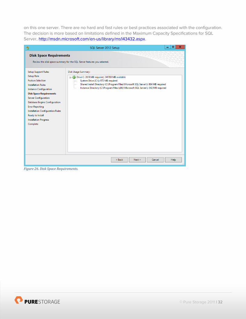
The Instance Configuration step is important as there needs to be a decision made to host a single
Default Instance of SQL Server or if you want to host multiple SQL Server instances, Named Instance,
© Pure Storage 2011 | 32
on this one server. There are no hard and fast rules or best practices associated with the configuration.
The decision is more based on limitations defined in the Maximum Capacity Specifications for SQL
Server, http://msdn.microsoft.com/en-us/library/ms143432.aspx.
Figure 26. Disk Space Requirements.

© Pure Storage 2011 | 33
Figure 27. Server Configuration.
Figure 28. Database Engine Configuration – Server Configuration.
© Pure Storage 2011 | 34
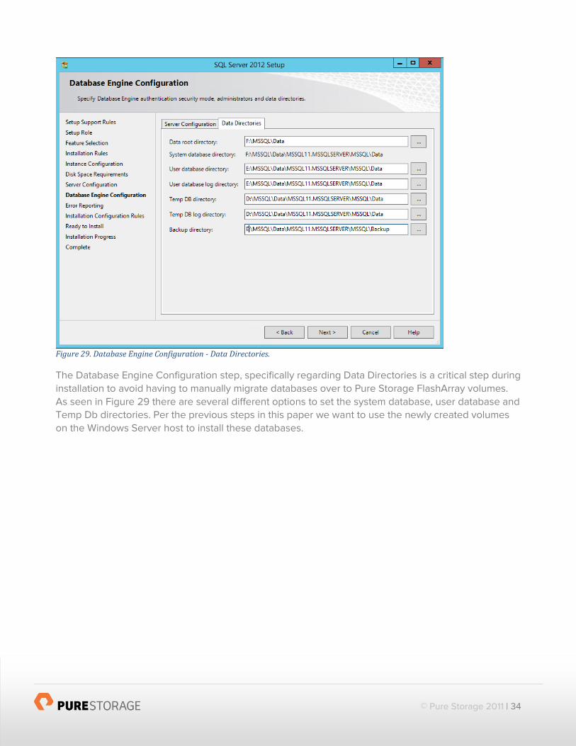
Figure 29. Database Engine Configuration - Data Directories.
The Database Engine Configuration step, specifically regarding Data Directories is a critical step during
installation to avoid having to manually migrate databases over to Pure Storage FlashArray volumes.
As seen in Figure 29 there are several different options to set the system database, user database and
Temp Db directories. Per the previous steps in this paper we want to use the newly created volumes
on the Windows Server host to install these databases.

© Pure Storage 2011 | 35
Figure 30. Error Reporting.
Don’t be alarmed with Figure 31 and the FAT32 File System as Passed. This is checking to make sure that the underlying file system is not FAT32.

© Pure Storage 2011 | 36
Figure 31. Installation Configuration Rules.
Figure 32. Ready to Install.
© Pure Storage 2011 | 37
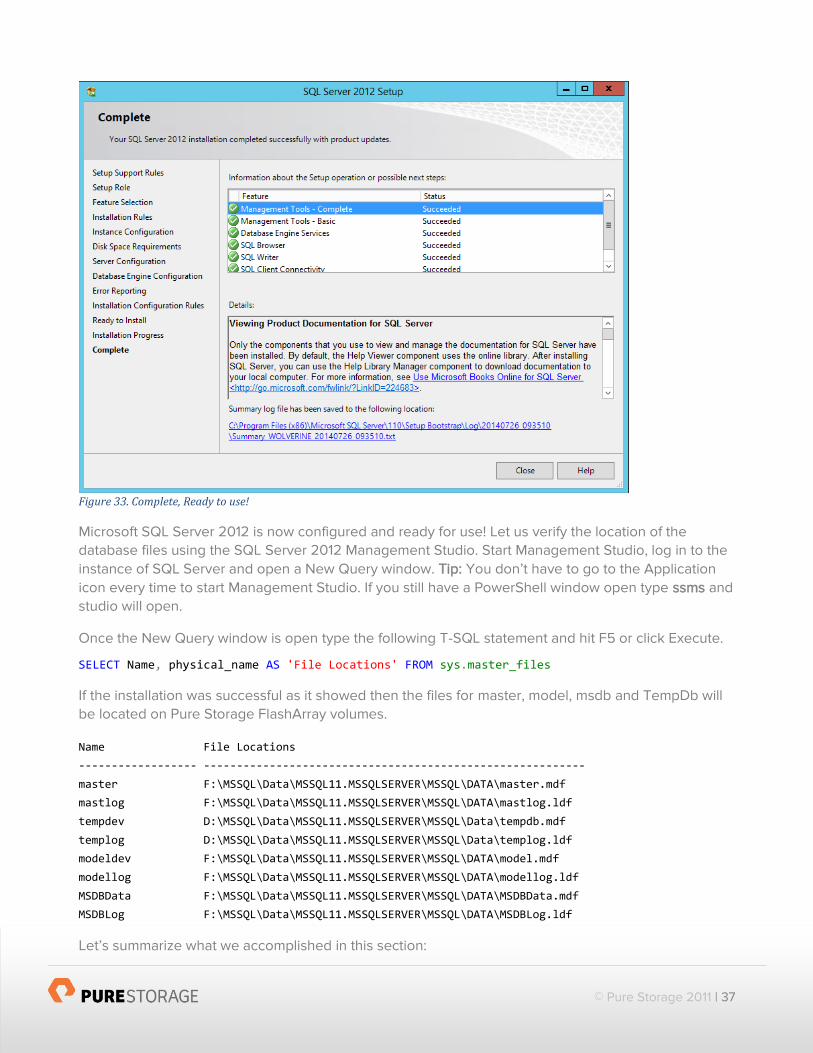
Figure 33. Complete, Ready to use!
Microsoft SQL Server 2012 is now configured and ready for use! Let us verify the location of the
database files using the SQL Server 2012 Management Studio. Start Management Studio, log in to the
instance of SQL Server and open a New Query window. Tip: You don’t have to go to the Application
icon every time to start Management Studio. If you still have a PowerShell window open type ssms and
studio will open.
Once the New Query window is open type the following T-SQL statement and hit F5 or click Execute.
SELECT Name, physical_name AS 'File Locations' FROM sys.master_files
If the installation was successful as it showed then the files for master, model, msdb and TempDb will
be located on Pure Storage FlashArray volumes.
Name File Locations
------------------ ----------------------------------------------------------
master F:\MSSQL\Data\MSSQL11.MSSQLSERVER\MSSQL\DATA\master.mdf
mastlog F:\MSSQL\Data\MSSQL11.MSSQLSERVER\MSSQL\DATA\mastlog.ldf
tempdev D:\MSSQL\Data\MSSQL11.MSSQLSERVER\MSSQL\Data\tempdb.mdf
templog D:\MSSQL\Data\MSSQL11.MSSQLSERVER\MSSQL\Data\templog.ldf
modeldev F:\MSSQL\Data\MSSQL11.MSSQLSERVER\MSSQL\DATA\model.mdf
modellog F:\MSSQL\Data\MSSQL11.MSSQLSERVER\MSSQL\DATA\modellog.ldf
MSDBData F:\MSSQL\Data\MSSQL11.MSSQLSERVER\MSSQL\DATA\MSDBData.mdf
MSDBLog F:\MSSQL\Data\MSSQL11.MSSQLSERVER\MSSQL\DATA\MSDBLog.ldf
Let’s summarize what we accomplished in this section:

© Pure Storage 2011 | 38
Installed Microsoft SQL Server 2012 as a stand-alone server
Set the Data Directories to install System, TempDb and User database on Pure Storage
FlashArray volumes.
Verified the location of the physical files.
Configuring TempDb
Now that SQL Server 2012 has successfully installed and is started, the final step is to add the
additional TempDb files for optimal performance before adding any user databases to the system. As
seen in the query results for the file locations the tempdev and templog files are located on
D:\MSSQL\Data\MSSQL11.MSSQLSERVER\MSSQL\Data\. This next operation will add six new tempdb
files.
Best Practices
When creating additional TempDb files ensure that all existing and new files are of the
same size for optimal performance.
Create one data file per physical or virtual CPU core for TempDb. In the example below 6
TempDb files are created since there are 12 cores in the server.
Preallocate space for all TempDb files by setting the file size to accommodate the
workload in the environment. This prevents TempDb from expanding too frequently,
which can affect performance.
Set TempDb to automatically grow. Preallocation should cover operational needs but
setting to auto grow is a safeguard for unplanned exceptions. In the below example each
TempDb file is set to grow by 100MB.
Monitor TempDb file sizes. In the below example the MAXSIZE of each TempDb file is set
to UNRESTRICTED which means keep growing until all volume capacity is used. Using
this setting requires that the SQL Server be monitored but any good DBA has alerts and
the like setup to warn of impending issues.
The T-SQL query to run using SQL Management Studio is as follows:
USE [master] GO ALTER DATABASE [tempdb] MODIFY FILE (NAME=N'tempdev', SIZE=1000MB, MAXSIZE=UNRESTRICTED, FILEGROWTH=100) GO ALTER DATABASE [tempdb] MODIFY FILE (NAME=N'templog', SIZE=1000MB, MAXSIZE=UNRESTRICTED, FILEGROWTH=100) GO

© Pure Storage 2011 | 39
ALTER DATABASE [tempdb] ADD FILE (NAME=N'tempdev1', FILENAME=N'D:\MSSQL\Data\MSSQL11.MSSQLSERVER\MSSQL\Data\tempdev1.ndf', SIZE=1000MB, MAXSIZE=UNRESTRICTED, FILEGROWTH=100) GO ALTER DATABASE [tempdb] ADD FILE (NAME=N'tempdev2', FILENAME=N'D:\MSSQL\Data\MSSQL11.MSSQLSERVER\MSSQL\Data\tempdev2.ndf', SIZE=1000MB, MAXSIZE=UNRESTRICTED, FILEGROWTH=100) GO ALTER DATABASE [tempdb] ADD FILE (NAME=N'tempdev3', FILENAME=N'D:\MSSQL\Data\MSSQL11.MSSQLSERVER\MSSQL\Data\tempdev3.ndf', SIZE=1000MB, MAXSIZE=UNRESTRICTED, FILEGROWTH=100) GO ALTER DATABASE [tempdb] ADD FILE (NAME=N'tempdev4', FILENAME=N'D:\MSSQL\Data\MSSQL11.MSSQLSERVER\MSSQL\Data\tempdev4.ndf', SIZE=1000MB, MAXSIZE=UNRESTRICTED, FILEGROWTH=100) GO ALTER DATABASE [tempdb] ADD FILE (NAME=N'tempdev5', FILENAME=N'D:\MSSQL\Data\MSSQL11.MSSQLSERVER\MSSQL\Data\tempdev5.ndf', SIZE=1000MB, MAXSIZE=UNRESTRICTED, FILEGROWTH=100) GO ALTER DATABASE [tempdb] ADD FILE (NAME=N'tempdev6', FILENAME=N'D:\MSSQL\Data\MSSQL11.MSSQLSERVER\MSSQL\Data\tempdev6.ndf', SIZE=1000MB, MAXSIZE=UNRESTRICTED, FILEGROWTH=100) GO
This query will create all the new files and result in Command(s) completed successfully.
That’s it! The system is fully configured to run a Microsoft SQL Server 2012 OLTP database.
Backup & Recovery
Backup and recoverability are paramount for any database application. With the release of the Purity
Operating Environment 4.0 we provide the Pure Storage Volume Shadow Copy Service Provider (Pure
VSS Provider). The Pure VSS Provider is a new plugin to download and install that takes application
consistent snapshots for Microsoft applications such as SQL Server.
It is important to set a foundation on the different types of backups before delving into the inner
workings of the Pure VSS Provider.
Inconsistent Backup
This is probably the oldest type of backup. The process is simple, backup software starts at the
beginning of a file structure and copies all of the data until it reaches the end, resulting in a backup.
What can make this backup inconsistent is that if any user added/modified after a backup but before it
completed that would result in an inconsistent backup; the files in the backup are not consistent. For
databases these types of backups do not provide adequate protection because they only capture
what is on disk. Example, with SQL Server there are a several different files, primary (MDF), log (LDF)
and secondary (NDF) files and there could be I/O (transactions) that are still in memory. The
inconsistent backup method only captures what is on disk and in the case of a database there may be
transactions still in memory.
Crash-Consistent Backup

© Pure Storage 2011 | 40
A crash-consistent backup is where all data is captured at the same point in time. For all things not
database related this method of backup should suffice for most recovery situations. A crash-consistent
backup, as with an inconsistent backup, does not capture any data that is in memory or any pending
I/O transactions. The term “crash” is used because if the data is recovered using this method it would
be equivalent to restoring to the exact moment that the server had crashed. Crash-consistent backups
can be used but it is important to perform the correct operational tasks to ensure you are restoring
properly. For example with SQL Server you may need to replay transaction logs to get the database
back to a consistent transactional state.
Any snapshot that is taken from the Pure Storage Web Management GUI, the Purity CLI or from
Windows PowerShell creates a crash-consistent snapshot. The Windows PowerShell and REST API
script has been included in Appendix I. Once a snapshot has been taken it can be created as a new
volume and connected to any host in the same method as illustrated previously in the Host
Management section.
Application-Consistent Backup
Application-consistent backups provide the highest level of protection and consistency, it captures
what is on disk and memory. For Microsoft Windows this is achieved using the Volume Shadow Copy
Service (VSS) which freezes I/O, flushes everything to disk and takes a block-level snapshot of the
volume. VSS is provided as a framework in the Windows operating system that performs these
operations by coordinating between Requester, Writer and Provider. When a VSS request is initiated a
VSS Writer (Eg. SqlServerWriter) will flush all I/O to ensure that the database is in a consistent state.
Then the VSS (Hardware) Provider will take a block-level snapshot of the volume. Once this is
completed the Provider notifies the Writer to resume operations.
Without the Pure Storage VSS Provider any snapshot that is taken is a crash consistent snapshot, with
the Pure VSS Provider we can now provide Application-Consistent Backups. When a Pure Storage VSS
snapshot is created it is marked with a .VSS# in order to distinguish between the two different types of
snapshots that can be taken. See Figure 34 for an example.

© Pure Storage 2011 | 41
Figure 34. VSS snapshot notation.
The Pure VSS Provider uses Diskshadow.exe as our out-of-box VSS Requester. Other requesters can
be used as long as they adhere to the implementation guidelines of the Volume Shadow Copy Service
Software Development kit (VSS SDK).
The process by which the Volume Shadow Copy Service works is illustrated below:
Steps in a VSS workflow are as follows:
1. The requester asks the Volume Shadow Copy Service to enumerate the writers, gather the writer
metadata, and prepare for shadow copy creation.
2. Each writer creates an XML description of the components and data stores that need to be
backed up and provides it to the Volume Shadow Copy Service. The writer also defines a restore
method, which is used for all components. The Volume Shadow Copy Service provides the
writer’s description to the requester, which selects the components that will be backed up.
3. The Volume Shadow Copy Service notifies all the writers to prepare their data for making a
shadow copy.
4. Each writer prepares the data as appropriate, such as completing all open transactions, rolling
transaction logs, and flushing caches. When the data is ready to be shadow-copied, the writer
notifies the Volume Shadow Copy Service.
5. The Volume Shadow Copy Service tells the writers to temporarily freeze application write I/O
requests (read I/O requests are still possible) for the few seconds that are required to create the
shadow copy of the volume or volumes. The application freeze is not allowed to take longer than
60 seconds. The Volume Shadow Copy Service flushes the file system buffers and then freezes
the file system, which ensures that the file system metadata is recorded correctly and the data to
be shadow-copied is written in a consistent order.
6. The Volume Shadow Copy Service tells the provider to create the shadow copy. The shadow
copy creation period lasts no more than 10 seconds, during which all write I/O requests to the file
system remain frozen.

© Pure Storage 2011 | 42
7. The Volume Shadow Copy Service releases file system write I/O requests.
8. VSS tells the writers to thaw application write I/O requests. At this point applications are free to
resume writing data to the disk that is being shadow-copied.
9. The requester can retry the process (go back to step 1) or notify the administrator to retry at a
later time.
10. If the shadow copy is successfully created, the Volume Shadow Copy Service returns the
location information for the shadow copy to the requester.
The new Pure VSS Provider can be installed from the Web Management GUI > System > Plugins > VSS.
Simply download the 1.0.0 package and install on the individual Microsoft Window Server hosts. It is
also possible to use other software deployment tools to install on a large volume of systems.
Figure 35. Pure Storage Web Management GUI Plugins.
Once the Pure VSS Provider has been installed use Diskshadow.exe from an elevated Administrator
prompt to ensure the provider is visible.

© Pure Storage 2011 | 43
DISKSHADOW > list providers
Figure 36. DISKSHADOW> list providers
All of the commands can be run directly from Diskshadow or via Windows PowerShell. All of the scripts
to perform Volume Shadow Copy Service snapshots are provided in Appendix IV and V.
Conclusion
This paper demonstrates the ease of configuring a Pure Storage FlashArray with Microsoft SQL Server
2012 for high availability and performance. A number of best practices were provided as guidelines
when deploying SQL Server in your environment. This paper explained:
Configuring server and hosts for optimal performance.
Configuring a host with Multipath I/O and a Host Bus Adapter.
Creating and connecting hosts via the Pure Storage Web Management GUI.
Creating specific volumes via the Pure Storage Web Management GUI for Microsoft SQL
Server.
Installing Microsoft SQL Server 2012 as a stand-alone server.
Modifying the configuration of SQL Server’s TempDb for optimal performance.

© Pure Storage 2011 | 44
With the Pure Storage FlashArray you can experience consistent sub-millisecond latency, I/O and
bandwidth for the most demanding SQL Server workloads. The OLTP tests that were performed as
part of this papers research would have required over 570 15,000 RPM SAS mechanical disks along
with the configuration and management of RAID setup, aggregate design, volume design and
management. A Microsoft SQL Server solution running on a Pure Storage FlashArray provides the
ability to deploy databases without the need to worry about sizing for performance again. Our overall
ease of array management, host connectivity and volume management gives productivity back to
storage administrators and DBAs where they need to spend the time; working with their customers.

© Pure Storage 2011 | 45
Appendix I: Snapshot Test Script
The following Windows PowerShell and Purity 3.4.3/REST API 1.1 was used to test taking snapshots of
the volume which contained the 2TB SQL Server database file. Each new snapshot gets assigned a
suffix with a Global Unique Identifier (GUID).
Note: Please update the script for $FlashArrayName, password and username with the appropriate
information.
cls [System.Net.ServicePointManager]::ServerCertificateValidationCallback = { $true } $FlashArrayName = “<NAME or IP Address>” $AuthAction = @{ password = "<USERNAME>" username = "<PASSWORD>" } Write-Host $AuthAction.Values $ApiToken = Invoke-RestMethod -Method Post -Uri "https://${FlashArrayName}/api/1.1/auth/apitoken" -Body $AuthAction $SessionAction = @{ api_token = $ApiToken.api_token } Invoke-RestMethod -Method Post -Uri "https://${FlashArrayName}/api/1.1/auth/session" -Body $SessionAction -SessionVariable Session "Start: {0::mm:ss}" -f (Get-Date) $SnapCount = 0 Do { $Snapshot = $null $Suffix = "REST-" + [Guid]::NewGuid() $Snapshot = [ordered]@{ snap = "true" source = [Object[]]"MEMPHIS-TPCE" suffix = $Suffix } | ConvertTo-Json Invoke-RestMethod -Method Post -Uri "https://${FlashArrayName}/api/1.1/volume" -Body $Snapshot -WebSession $Session -ContentType "application/json" $SnapCount++ } While ($SnapCount -le 1) "End: {0::mm:ss}" -f (Get-Date)
Appendix II: FlashArray Management Scripts
The following Windows PowerShell and Purity 3.4.3 REST/API 1.1 script can be customized to create the
basic volumes for deploying Microsoft SQL Server 2012. This script will create 3 new volumes, SQL-
SYSDBS (1GB), SQL-USERDBS (2TB), SQL-TEMPDB (1TB).
Note: Please update the script for $FlashArrayName, password and username with the appropriate
information.
cls [System.Net.ServicePointManager]::ServerCertificateValidationCallback = { $true } $FlashArrayName = “<NAME or IP Address>” $AuthAction = @{ password = "<USERNAME>" username = "<PASSWORD>" } Write-Host $AuthAction.Values

© Pure Storage 2011 | 46
$ApiToken = Invoke-RestMethod -Method Post -Uri "https://${FlashArrayName}/api/1.1/auth/apitoken" -Body $AuthAction $SessionAction = @{ api_token = $ApiToken.api_token } Invoke-RestMethod -Method Post -Uri "https://${FlashArrayName}/api/1.1/auth/session" -Body $SessionAction -SessionVariable Session Invoke-RestMethod -Method Get -Uri "https://${FlashArrayName}/api/1.1/array" -WebSession $Session | Format-Table -AutoSize $Size = $null $SQLsys = "SQL-SYSDBS" $SQLuser = "SQL-USERDBS" $SQLtemp = "SQL-TEMPDB" $SizeSQLsys = [ordered]@{ size = "1G" } | ConvertTo-Json $SizeSQLuser = [ordered]@{ size = "2T" } | ConvertTo-Json $SizeSQLtemp = [ordered]@{ size = "1T" } | ConvertTo-Json Invoke-RestMethod -Method Post -Uri "https://${FlashArrayName}/api/1.1/volume/$SQLsys" -Body $SizeSQLsys -WebSession $Session -ContentType "application/json" Invoke-RestMethod -Method Post -Uri "https://${FlashArrayName}/api/1.1/volume/$SQLuser" -Body $SizeSQLuser -WebSession $Session -ContentType "application/json" Invoke-RestMethod -Method Post -Uri "https://${FlashArrayName}/api/1.1/volume/$SQLtemp" -Body $SizeSQLtemp -WebSession $Session -ContentType "application/json" Invoke-RestMethod -Method Delete -Uri "https://${FlashArrayName}/api/1.1/auth/session" -WebSession $Session
Appendix III: Get Host Bus Adapter (HBA) Details
The following Windows PowerShell will retrieve all details about HBAs connected to a server. By
changing the –ComputerName parameter any server can be queried.
Function Get-HBAInfo { [CmdletBinding()] Param ( [Parameter(Mandatory=$false, ValueFromPipeline=$true, Position=0)] $ComputerName ) Begin { $Namespace = "root\WMI" } Process { $port = Get-WmiObject -Class MSFC_FibrePortHBAAttributes -Namespace $Namespace @PSBoundParameters $hbas = Get-WmiObject -Class MSFC_FCAdapterHBAAttributes -Namespace $Namespace @PSBoundParameters $hbaProp = $hbas | Get-Member -MemberType Property, AliasProperty | Select -ExpandProperty name | ? {$_ -notlike "__*"} $hbas = $hbas | Select $hbaProp $hbas | %{ $_.NodeWWN = ((($_.NodeWWN) | % {"{0:x2}" -f $_}) -join ":").ToUpper() } ForEach($hba in $hbas) {

© Pure Storage 2011 | 47
Add-Member -MemberType NoteProperty -InputObject $hba -Name FabricName -Value ( ($port |? { $_.instancename -eq $hba.instancename}).attributes | ` Select ` @{Name='Fabric Name';Expression={(($_.fabricname | % {"{0:x2}" -f $_}) -join ":").ToUpper()}}, ` @{Name='Port WWN';Expression={(($_.PortWWN | % {"{0:x2}" -f $_}) -join ":").ToUpper()}} ) -passThru } } } Get-HBAInfo -ComputerName $env:COMPUTERNAME
Appendix IV: New-PfaVolShadowCopy.ps1
[CmdletBinding()] Param( [Parameter(Mandatory=$True)][string]$Volume, [Parameter(Mandatory=$True)][string]$ScriptName, [Parameter(Mandatory=$True)][string]$MetadataFile, [Parameter(Mandatory=$True)][string]$ShadowCopyAlias, [Parameter(Mandatory=$True)][string]$VerboseMode = "ON" ) $dsh = "./$ScriptName.dsh" "RESET", "SET CONTEXT PERSISTENT", "SET OPTION TRANSPORTABLE", "SET METADATA $MetadataFile", "SET VERBOSE $VerboseMode", "BEGIN BACKUP", "ADD VOLUME $Volume ALIAS $ShadowCopyAlias PROVIDER {781c006a-5829-4a25-81e3-d5e43bd005ab}", "CREATE", "END BACKUP" | Set-Content $dsh DISKSHADOW /s $dsh Remove-Item $dsh
Appendix V: Get-PfaVolShadowCopy.ps1
[CmdletBinding()] Param( [Parameter(Mandatory=$True)][string]$MetadataFile, [Parameter(Mandatory=$True)][string]$ShadowCopyAlias, [Parameter(Mandatory=$True)][string]$ExposeAs ) $dsh = "./$ScriptName.dsh" "RESET", "LOAD METADATA $MetadataFile", "IMPORT", "EXPOSE %$ShadowCopyAlias% $ExposeAs", "EXIT" | Set-Content $dsh DISKSHADOW /s $dsh Remove-Item $dsh

© Pure Storage 2011 | 48
References
The following references where used as part of the development of this document.
1. SQLIO Disk Subsystem Benchmark Tool, http://www.microsoft.com/en-
us/download/details.aspx?id=20163.
2. Microsoft Windows Server Best Practice Guide for Pure Storage,
http://info.purestorage.com/WP-MicrosoftWindowsServerBestPracticeGuide_Request.html.
3. Multipath I/O Overview, http://technet.microsoft.com/en-us/library/cc725907.aspx.
4. Understanding MPIO Features and Components, http://technet.microsoft.com/en-
us/library/ee619734(v=WS.10).aspx.
5. Microsoft Multipath I/O (MPIO) Users Guide for Windows Server 2012,
http://www.microsoft.com/en-us/download/details.aspx?id=30450.
6. Volume Shadow Copy Service, http://msdn.microsoft.com/en-
us/library/ee923636(v=WS.10).aspx.
7. Diskshadow, http://technet.microsoft.com/en-us/library/cc772172.aspx.
8. Windows Performance Monitor Disk Counters Explained,
http://blogs.technet.com/b/askcore/archive/2012/03/16/windows-performance-monitor-disk-
counters-explained.aspx
9. sp_configure (Transact-SQL), http://msdn.microsoft.com/en-us/library/ms188787(v=sql.110).aspx.
10. RECONFIGURE, http://msdn.microsoft.com/en-us/library/ms176069(v=sql.110).aspx.
11. QLogic Fibre Channel Adapter Stor Miniport Driver,
http://filedownloads.qlogic.com/files/driver/42560/Readme_FC_StorPort_9-1-2-16.htm
12. Application Consistency with Pure Storage VSS Provider,
http://www.themicrosoftdude.com/?p=2131
13. Pure Storage PowerShell Toolkit 1.0, http://www.purestorage.com/blog/pure-storage-
powershell-toolkit-1-0/.

© Pure Storage 2011 | 49
Pure Storage, Inc. Twitter: @purestorage
650 Castro Street, Suite #400
Mountain View, CA 94041
T: 650-290-6088 F: 650-625-9667
Sales: [email protected]
Support: [email protected] Media: [email protected]
General: [email protected]