Embed Size (px)
Citation preview
MICROtrac
MICROPROCESSOR – BASED WATER TREATMENT CONTROLLER
Installation and Operation Manual
72-910-02
REV. N
2
MICROtrac Warranty
Pulsafeeder, Inc. warrants MICROtrac control systems (including the conductivity sensor) of its
manufacture to be free of defects in material or workmanship. Liability under this policy extends for 24
months from date of shipment. The manufacturer's liability is limited to repair or replacement of any
failed equipment or part, which is proven defective in material or workmanship upon completion of the
manufacturer's examination. This warranty does not include removal or installation costs and in no event
shall the manufacturer's liability exceed the selling price of such equipment or part.
The manufacturer disclaims all liability for damage to its products through improper installation,
maintenance, use, or attempts to operate such products beyond their functional capacity, intentionally or
otherwise, or any unauthorized repair. The manufacturer is not responsible for consequential or other
damages, injuries, or expense incurred through the use of its products.
The above warranty is in lieu of any other warranty, whether expressed or implied. The manufacturer
makes no warranty of fitness or merchantability. No agent of ours is authorized to provide any warranty
other than the above.
72-910-02
REV. N
3
Table of Contents
1. INTRODUCTION ....................................................................................... 4
2. INSTALLATION ........................................................................................ 4
2.1 Controller Location ........................................................................ 4
2.2 Sensor Installation ......................................................................... 4
3. ELECTRICAL WIRING ............................................................................... 6
3.1 Electrical Connections ................................................................... 7
4. SYSTEM OPERATION ............................................................................... 9
4.1 Front Panel .................................................................................... 9
4.2 System Functions .......................................................................... 10
4.3 Controller Programming ................................................................ 11
4.3.1 Control Modes .......................................................................... 11
4.3.2 Conductivity Set Point .............................................................. 13
4.4 Alarm Conditions ........................................................................... 13
5. SENSOR CALIBRATION ............................................................................ 14
6. FACTORY DEFAULT VALUES .................................................................... 14
7. SPECIFICATIONS ..................................................................................... 15
8. TROUBLE SHOOTING GUIDE .................................................................... 17
9. CONTROLLER MOUNTING DIMENSIONS ..................................................... 18
10. ADDENDUM: MICROTRAC PC BOARD REPLACEMENT ..................... 19
11. MICROTRAC FACTORY SERVICE POLICY ...................................... 20
72-910-02
REV. N
4
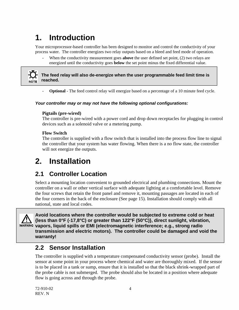
1. Introduction Your microprocessor-based controller has been designed to monitor and control the conductivity of your
process water. The controller energizes two relay outputs based on a bleed and feed mode of operation.
- When the conductivity measurement goes above the user defined set point, (2) two relays are
energized until the conductivity goes below the set point minus the fixed differential value.
The feed relay will also de-energize when the user programmable feed limit time is reached.
- Optional - The feed control relay will energize based on a percentage of a 10 minute feed cycle.
Your controller may or may not have the following optional configurations:
Pigtails (pre-wired)
The controller is pre-wired with a power cord and drop down receptacles for plugging in control
devices such as a solenoid valve or a metering pump.
Flow Switch
The controller is supplied with a flow switch that is installed into the process flow line to signal
the controller that your system has water flowing. When there is a no flow state, the controller
will not energize the outputs.
2. Installation
2.1 Controller Location
Select a mounting location convenient to grounded electrical and plumbing connections. Mount the
controller on a wall or other vertical surface with adequate lighting at a comfortable level. Remove
the four screws that retain the front panel and remove it, mounting passages are located in each of
the four corners in the back of the enclosure (See page 15). Installation should comply with all
national, state and local codes.
Avoid locations where the controller would be subjected to extreme cold or heat {less than 0°F (-17,8°C) or greater than 122°F (50°C)}, direct sunlight, vibration, vapors, liquid spills or EMI (electromagnetic interference; e.g., strong radio transmission and electric motors). The controller could be damaged and void the warranty!
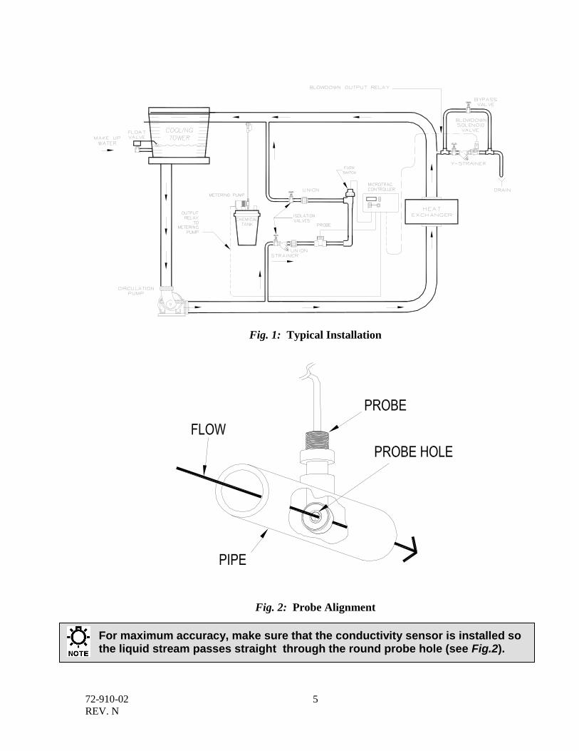
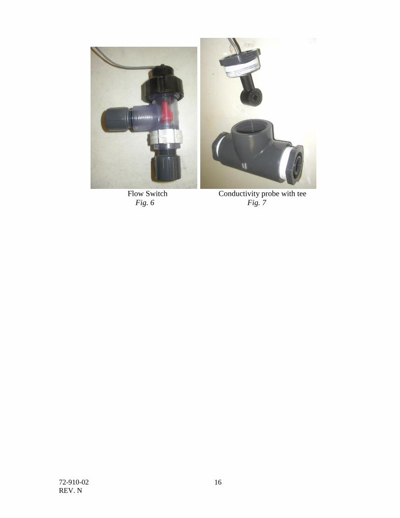
2.2 Sensor Installation
The controller is supplied with a temperature compensated conductivity sensor (probe). Install the
sensor at some point in your process where chemical and water are thoroughly mixed. If the sensor
is to be placed in a tank or sump, ensure that it is installed so that the black shrink-wrapped part of
the probe cable is not submerged. The probe should also be located in a position where adequate
flow is going across and through the probe.
72-910-02
REV. N
5
Fig. 1: Typical Installation
Fig. 2: Probe Alignment
For maximum accuracy, make sure that the conductivity sensor is installed so the liquid stream passes straight through the round probe hole (see Fig.2).
72-910-02
REV. N
6
Flow Sensor If your controller is provided with a flow switch, install the flow switch so that flow enters into the
bottom of the provided flow switch tee, and out of the side of the tee. The flow switch must always
be installed in a vertical position so that the sensor wire is coming out of the top, and the internal
(red) flow shuttle is able to rise when there is flow and drop when there is not flow. The flow switch
is activated when 1 GPM (3.8 LPM) is going through it, and is deactivated when the flow drops
below 1 GPM (3.8 LPM).
3. Electrical Wiring1
The controller electronic circuitry is fuse protected. Use of a surge protector and Ground Fault
Circuit Interrupter (GFCI) are strongly recommended!
Controller must be wired in accordance with all applicable electrical codes.
Input power must be 120 or 220VAC Single Phase.
Trained service personnel are required for all electrical connections. This product
does not contain operator serviceable parts.
Devices attached to any Relay connection must be Single Phase and rated for the
same voltage as the input voltage to the product. (e. g. 120VAC MicroTrac controllers support 120VAC relay attached devices exclusively and 220VAC MicroTrac controller support 220VAC relay attached devices exclusively.) Do not apply power until this condition is verified.
Input power cord must be disconnected from power source prior to opening the
product’s enclosure and making any electrical connections.
The controller should be connected to a dedicated power branch (i.e., its own wiring, circuit breaker, etc.). For best results, the ground should be independent (true earth) not shared.
A switch or circuit-breaker, marked as the unit’s disconnecting device should be included in the installation. It should be in close proximity to the unit and easily reached by the user.
1 Trained service personnel are required for all electrical connections. This product does not contain operator serviceable
parts.
72-910-02
REV. N
7
Pre-wired controllers are supplied with 6 ft (1,8 m), 18 AWG (1,2 mm2) 3-wire grounded power
cords and clearly marked 18 AWG (1,2 mm2) 3-wire grounded receptacle cords for all controlled
line voltage outputs.
Controllers that are to use electrical conduit are factory pre-drilled with easily accessible connections
for hard wiring of input and output power connections. Use only 16 AWG (1,5 mm2) or 18 AWG
(1,2 mm2) wire for conduit power and load connections.
3.1 Electrical Connections2
If your controller was not ordered as a pre-wired controller, hard wiring will be required. With the
main power disconnected from the controller, loosen the four screws that retain the front panel of the
controller and remove the front panel. There are five terminal block connectors inside the controller
that will need to be wired.
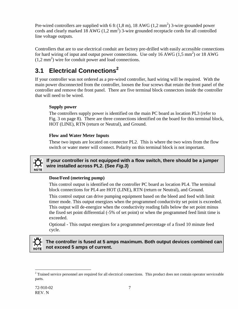
Supply power
The controllers supply power is identified on the main PC board as location PL3 (refer to
Fig. 3 on page 8). There are three connections identified on the board for this terminal block,
HOT (LINE), RTN (return or Neutral), and Ground.
Flow and Water Meter Inputs
These two inputs are located on connector PL2. This is where the two wires from the flow
switch or water meter will connect. Polarity on this terminal block is not important.
If your controller is not equipped with a flow switch, there should be a jumper wire installed across PL2. (See Fig.3)
Dose/Feed (metering pump)
This control output is identified on the controller PC board as location PL4. The terminal
block connections for PL4 are HOT (LINE), RTN (return or Neutral), and Ground.
This control output can drive pumping equipment based on the bleed and feed with limit
timer mode. This output energizes when the programmed conductivity set point is exceeded.
This output will de-energize when the conductivity reading falls below the set point minus
the fixed set point differential (-5% of set point) or when the programmed feed limit time is
exceeded.
Optional - This output energizes for a programmed percentage of a fixed 10 minute feed
cycle.
The controller is fused at 5 amps maximum. Both output devices combined can not exceed 5 amps of current.
2 Trained service personnel are required for all electrical connections. This product does not contain operator serviceable
parts.
72-910-02
REV. N
8
Bleed (solenoid valve)
This control output is identified on the controller PC board as location PL5. The terminal
block connections for PL5 are HOT (LINE), RTN (return or Neutral), and Ground.
This control output will energize when the programmed conductivity set point is exceeded.
This output will de-energize when the conductivity reading falls below the set point minus
the fixed set point differential (-5% of set point).
Conductivity Probe
The controller is supplied with one temperature compensated conductivity sensor. The
sensor connects to PL1 of the controller PC board. Match the wire color from the probe with
the text next to connector PL1.
DOSE PL4
RET HOTno
HO
T
F1 5A
SUPPLY PL3
RET HOT
RET
nc H
OT
PL5
BLEED
F2 5A
CO
M
FLO
W
CO
M
WA
TE
R
ME
TE
R
BLACK
BROWN
ORANGE
RED
CONDUCTIVITY
SENSOR
1 2 3 4
ON DIP
SW1
PL2
FLOW
SWITCH
CONTACT
METER
TOROIDAL
PROBE
HO
TR
ET
HO
TR
ET
MOTORIZED BALL VALVE
(RETURN / NEUTRAL)
(EARTH / CHASSIS GROUND)
(NORMALLY / OPEN)
(NORMALLY / CLOSED)
FUSES
SUPPLY
POWER
DIP
SWITCH
PUMP
(3-WIRE)
PL1
(NORMALLY OPEN)
(EARTH / CHASSIS GROUND)
(RETURN/NEUTRAL)
(4-WIRE)
Fig. 3: Wire Connections
3
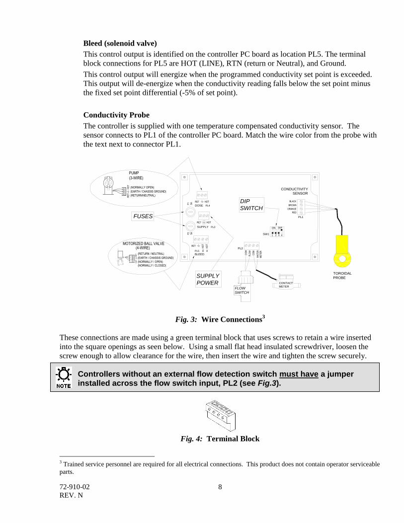
These connections are made using a green terminal block that uses screws to retain a wire inserted
into the square openings as seen below. Using a small flat head insulated screwdriver, loosen the
screw enough to allow clearance for the wire, then insert the wire and tighten the screw securely. Controllers without an external flow detection switch must have a jumper installed across the flow switch input, PL2 (see Fig.3).
Fig. 4: Terminal Block
3 Trained service personnel are required for all electrical connections. This product does not contain operator serviceable
parts.
72-910-02
REV. N
9
4. System Operation BEFORE APPLYING POWER, INSURE THAT DEVICES BEING CONTROLLED BY THIS
CONTROLLER ARE NOT IN A POSITION TO CAUSE HARM OR DAMAGE IF ENERGIZED UPON
INITIAL START-UP.
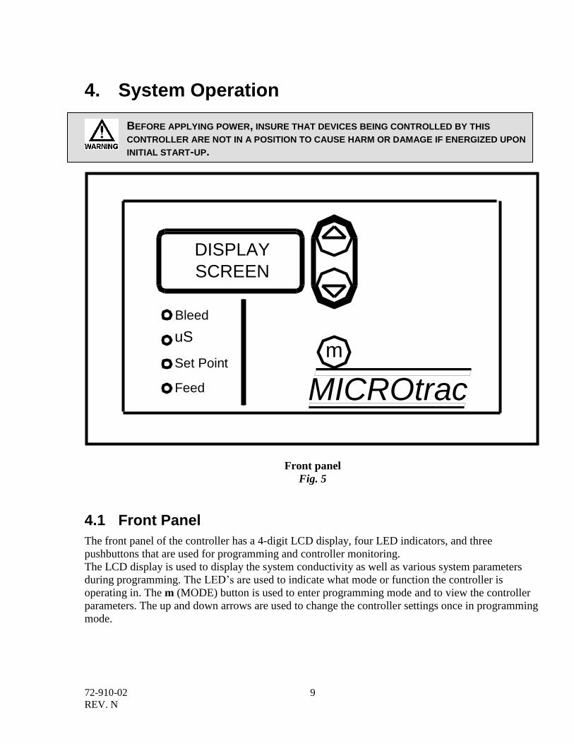
Front panel
Fig. 5
4.1 Front Panel
The front panel of the controller has a 4-digit LCD display, four LED indicators, and three
pushbuttons that are used for programming and controller monitoring.
The LCD display is used to display the system conductivity as well as various system parameters
during programming. The LED’s are used to indicate what mode or function the controller is
operating in. The m (MODE) button is used to enter programming mode and to view the controller
parameters. The up and down arrows are used to change the controller settings once in programming
mode.
DISPLAY
SCREEN
m
MICROtrac
Bleed
uS
Set Point
Feed
72-910-02
REV. N
10
4.2 System Functions
Bleed The bleed LED will light when the bleed relay is energized in normal
operation or when the controller is displaying the bleed limit time setting.
When in programming mode this LED will flash indicating it is okay to
change the bleed limit time setting.
uS The uS LED will light when the controller is displaying the system
conductivity reading. The controller displays this during normal operation or
when there has been no button activity for 30 seconds. When calibrating the
probe this LED will flash indicating it is okay to change the probe
conductivity value.
Set Point The set point LED will light when the controller is displaying the
conductivity set point. The set point is the conductivity value that will
energize the Bleed and Dose relays. When in programming mode this LED
will flash indicating it is okay to change the set point setting.
Feed This LED will light when the “Dose” or feed relay is energized. When in
programming mode this LED will flash indicating it is okay to change the
feed limit time setting.
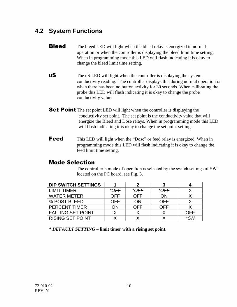
Mode Selection
The controller’s mode of operation is selected by the switch settings of SW1
located on the PC board, see Fig. 3.
DIP SWITCH SETTINGS 1 2 3 4
LIMIT TIMER *OFF *OFF *OFF X
WATER METER OFF OFF ON X
% POST BLEED OFF ON OFF X
PERCENT TIMER ON OFF OFF X
FALLING SET POINT X X X OFF
RISING SET POINT X X X *ON
* DEFAULT SETTING – limit timer with a rising set point.
72-910-02
REV. N
11
4.3 Controller Programming
Press the Mode button to advance to the setting to be changed indicated by the function’s LED. To
enter programming mode press and hold the Mode [m] button for five seconds. The function’s LED
will begin to flash when the programming mode has been activated. Use the [Up]/[Down] buttons to
modify the programmable parameters.
During programming normal controller operation is suspended. If no keys are pressed for 30 seconds the controller will exit programming mode and return to normal operation.
4.3.1 Control Modes
Listed below are the different control modes of the MicroTrac controller. Each control mode uses
simple parameters for user modifications.
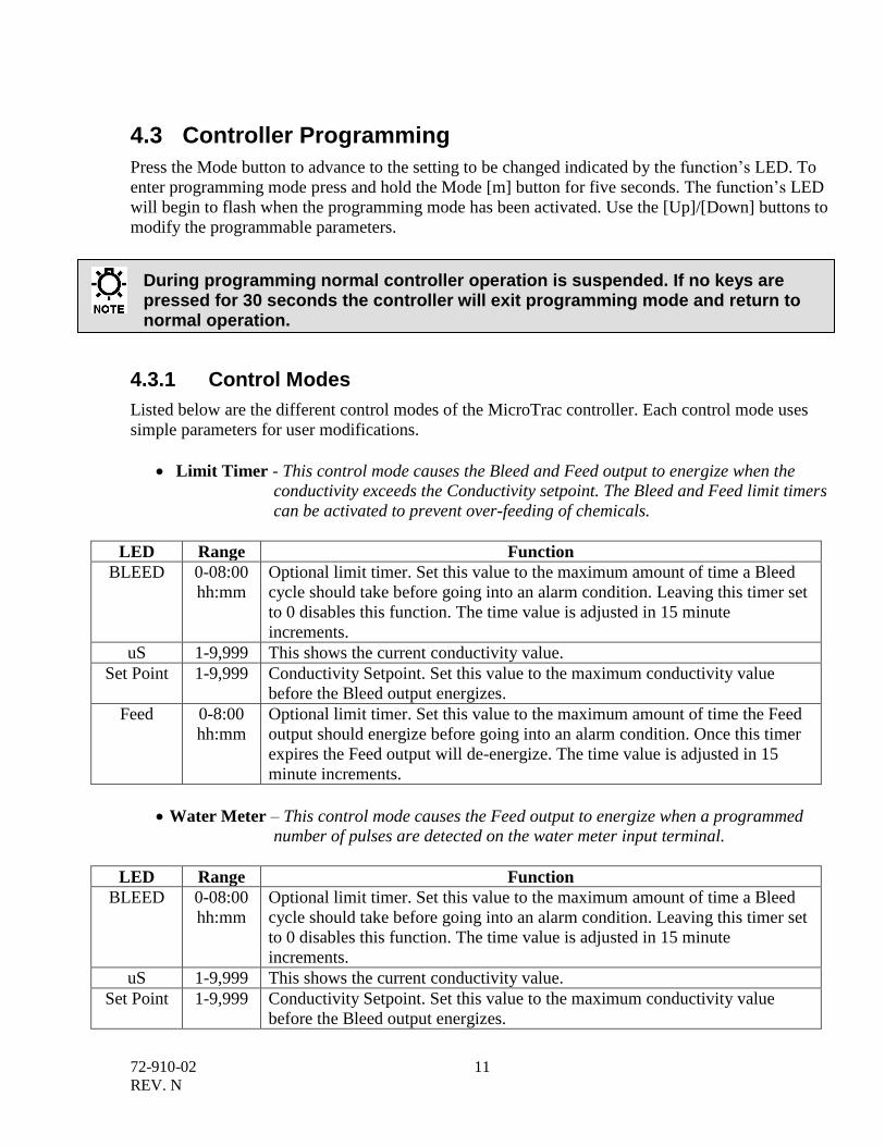
Limit Timer - This control mode causes the Bleed and Feed output to energize when the
conductivity exceeds the Conductivity setpoint. The Bleed and Feed limit timers
can be activated to prevent over-feeding of chemicals.
LED Range Function
BLEED 0-08:00
hh:mm
Optional limit timer. Set this value to the maximum amount of time a Bleed
cycle should take before going into an alarm condition. Leaving this timer set
to 0 disables this function. The time value is adjusted in 15 minute
increments.
uS 1-9,999 This shows the current conductivity value.
Set Point 1-9,999 Conductivity Setpoint. Set this value to the maximum conductivity value
before the Bleed output energizes.
Feed 0-8:00
hh:mm
Optional limit timer. Set this value to the maximum amount of time the Feed
output should energize before going into an alarm condition. Once this timer
expires the Feed output will de-energize. The time value is adjusted in 15
minute increments.
Water Meter – This control mode causes the Feed output to energize when a programmed
number of pulses are detected on the water meter input terminal.
LED Range Function
BLEED 0-08:00
hh:mm
Optional limit timer. Set this value to the maximum amount of time a Bleed
cycle should take before going into an alarm condition. Leaving this timer set
to 0 disables this function. The time value is adjusted in 15 minute
increments.
uS 1-9,999 This shows the current conductivity value.
Set Point 1-9,999 Conductivity Setpoint. Set this value to the maximum conductivity value
before the Bleed output energizes.
72-910-02
REV. N
12
Feed Counts
+ Time
Counts – Set this value to the number of water meter input pulses needed
before the Feed cycle begins. Range = 1-9,999.
Time – Set this value to the amount of time the Feed output should energize
when the programmed number of water meter input pulses have been
detected. Range = 0-59:55, MM:SS. The time value is adjusted in 5 second
increments.
% Post Bleed – This control mode causes the Feed output to energize following a Bleed
cycle. The amount of time the Feed output stays energized is based on the
programmed percentage of the prior Bleed cycle.
LED Range Function
BLEED 0-08:00
hh:mm
Optional limit timer. Set this value to the maximum amount of time a Bleed
cycle should take before going into an alarm condition. Leaving this timer set
to 0 disables this function. The time value is adjusted in 15 minute
increments.
uS 1-9,999 This shows the current conductivity value.
Set Point 1-9,999 Conductivity Setpoint. Set this value to the maximum conductivity value
before the Bleed output energizes.
Feed Percent
+ Time
Percentage – Set this value to a percentage of the prior Bleed cycle the Feed
output should energize. Example: Percent=25, Bleed cycle took 14 minutes,
the Feed output would energize for 25% of 14 minutes, or 3.5 minutes. Range
= 0-100.
Time – Optional limit timer. Set this value to the maximum amount of time
the Feed output should energize before going into an alarm condition. Once
this timer expires the Feed output will de-energize. Range = 0-08:00, hh:mm.
The time value is adjusted in 15 minute increments.
Percent Timer – This control mode causes the Feed output to energize based on a
percentage of a fixed time cycle. The cycle time is base on a fixed 10-minute
cycle. Once the 10-minute cycle completes the cycle will be restarted again.
LED Range Function
BLEED 0-08:00
hh:mm
Optional limit timer. Set this value to the maximum amount of time a Bleed
cycle should take before going into an alarm condition. Leaving this timer set
to 0 disables this function.
uS 1-9,999 This shows the current conductivity value.
Set Point 1-9,999 Conductivity Setpoint. Set this value to the maximum conductivity value
before the Bleed output energizes.
Feed Percent Percentage – Set this value to a percentage of the 10-minute cycle time.
Example: Percent=20, cycle time of 10 minutes, the Feed output would
energize for 20% of 10 minutes, or 2 minutes. Range = 0-100.
72-910-02
REV. N
13
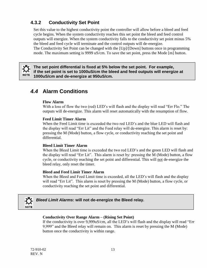
4.3.2 Conductivity Set Point
Set this value to the highest conductivity point the controller will allow before a bleed and feed
cycle begins. When the system conductivity reaches this set point the bleed and feed control
outputs will energize. When the system conductivity falls to the conductivity set point minus 5%
the bleed and feed cycle will terminate and the control outputs will de-energize.
The Conductivity Set Point can be changed with the [Up]/[Down] buttons once in programming
mode. The maximum setting is 9999 uS/cm. To save the set point, press the Mode [m] button.
The set point differential is fixed at 5% below the set point. For example, if the set point is set to 1000uS/cm the bleed and feed outputs will energize at 1000uS/cm and de-energize at 950uS/cm.
4.4 Alarm Conditions
Flow Alarm
With a loss of flow the two (red) LED’s will flash and the display will read “Err Flo.” The
outputs will de-energize. This alarm will reset automatically with the resumption of flow.
Feed Limit Timer Alarm
When the Feed Limit time is exceeded the two red LED’s and the blue LED will flash and
the display will read “Err Lit” and the Feed relay will de-energize. This alarm is reset by:
pressing the M (Mode) button, a flow cycle, or conductivity reaching the set point and
differential.
Bleed Limit Timer Alarm
When the Bleed Limit time is exceeded the two red LED’s and the green LED will flash and
the display will read “Err Lit”. This alarm is reset by: pressing the M (Mode) button, a flow
cycle, or conductivity reaching the set point and differential. This will not de-energize the
bleed relay, only reset the timer.
Bleed and Feed Limit Timer Alarm
When the Bleed and Feed Limit time is exceeded, all the LED’s will flash and the display
will read “Err Lit”. This alarm is reset by pressing the M (Mode) button, a flow cycle, or
conductivity reaching the set point and differential.
Bleed Limit Alarms: will not de-energize the Bleed relay.
Conductivity Over Range Alarm – (Rising Set Point)
If the conductivity is over 9,999uS/cm, all the LED’s will flash and the display will read “Err
9,999” and the Bleed relay will remain on. This alarm is reset by pressing the M (Mode)
button once the conductivity is within range.
72-910-02
REV. N
14
Both Limit Timers will reset if the conductivity reading changes to above or below the set point and differential.
5. Sensor Calibration The controller is factory calibrated and requires no user adjustments. Some deviation in the reading
may be expected when compared to a hand-held tester. However, if you wish to perform a
calibration, follow this procedure:
1. Place the probe in the process that it will normally be installed in and allow flow across the
probe for approximately 15 minutes. This will allow the probe temperature to equalize.
2. While the “uS” LED is steady press and hold the “m” mode button for five seconds until the
controller flashes “Cal”. Release the “m” button.
1. The controller will now display the actual conductivity reading from the probe. Use the up
and down buttons to change the reading until it matches your hand-held’s reading. If you
press and hold the up or down buttons, the displayed value will change very quickly.
4. When finished press the “m” button once.
IMPORTANT! For optimum performance, make sure that the system conductivity is near
the set point that you intend to operate the system.
The calibration process is now complete.
6. Factory Default Values Set point: 1500µS/cm
Bleed Limit timer: 00:00, HH:MM
Feed Limit timer: 00:00, HH:MM
72-910-02
REV. N
15
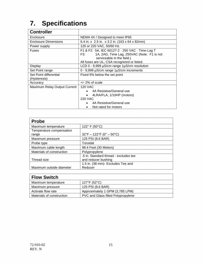
7. Specifications
Controller
Enclosure NEMA 4X / Designed to meet IP65
Enclosure Dimensions 6.4 in. x 2.5 in. x 3.2 in. (163 x 64 x 82mm)
Power supply 120 or 220 VAC, 50/60 Hz.
Fuses F1 & F2: 5A, IEC 60127-2 · 250 VAC · Time-Lag T F3: 1A, 2AG, Time Lag, 250VAC (Note: F1 is not serviceable in the field.) All fuses are UL, CSA recognized or listed.
Display LCD 0 - 9,999 µS/cm range 1µS/cm resolution
Set Point range 0 - 9,999 µS/cm range 1µS/cm increments
Set Point differential (Hysteresis)
Fixed 5% below the set point
Accuracy +/- 2% of scale
Maximum Relay Output Current 120 VAC
4A Resistive/General use
4LRA/FLA, 1/10HP (motors) 220 VAC
4A Resistive/General use
Not rated for motors
Probe
Maximum temperature 122° F (50°C)
Temperature compensation range 32°F – 122°F (0° – 50°C)
Maximum pressure 125 PSI (8.6 BAR)
Probe type Toroidal
Maximum cable length 98.4 Feet (30 Meters)
Materials of construction Polypropylene
Thread size .5 in. Standard thread - excludes tee and reducer bushing
Maximum outside diameter 1.5 in. (38 mm)- Excludes Tee and Reducer
Flow Switch
Maximum temperature 127°F (52°C)
Maximum pressure 125 PSI (8,6 BAR)
Activate flow rate Approximately 1 GPM (3,785 LPM)
Materials of construction PVC and Glass filled Polypropylene
72-910-02
REV. N
16
Flow Switch Conductivity probe with tee
Fig. 6 Fig. 7
72-910-02
REV. N
17
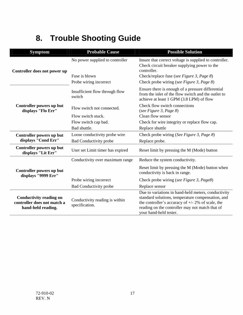
8. Trouble Shooting Guide
Symptom Probable Cause Possible Solution
Controller does not power up
No power supplied to controller Insure that correct voltage is supplied to controller.
Check circuit breaker supplying power to the
controller.
Fuse is blown Check/replace fuse (see Figure 3, Page 8)
Probe wiring incorrect Check probe wiring (see Figure 3, Page 8)
Controller powers up but
displays "Flo Err"
Insufficient flow through flow
switch
Ensure there is enough of a pressure differential
from the inlet of the flow switch and the outlet to
achieve at least 1 GPM (3.8 LPM) of flow
Flow switch not connected. Check flow switch connections
(see Figure 3, Page 8)
Flow switch stuck. Clean flow sensor
Flow switch cap bad. Check for wire integrity or replace flow cap.
Bad shuttle. Replace shuttle
Controller powers up but
displays "Cond Err"
Loose conductivity probe wire Check probe wiring (See Figure 3, Page 8)
Bad Conductivity probe Replace probe.
Controller powers up but
displays "Lit Err" User set Limit timer has expired Reset limit by pressing the M (Mode) button
Controller powers up but
displays "9999 Err"
Conductivity over maximum range Reduce the system conductivity.
Reset limit by pressing the M (Mode) button when
conductivity is back in range.
Probe wiring incorrect Check probe wiring (see Figure 3, Page8)
Bad Conductivity probe Replace sensor
Conductivity reading on
controller does not match a
hand-held reading.
Conductivity reading is within
specification.
Due to variations in hand-held meters, conductivity
standard solutions, temperature compensation, and
the controller’s accuracy of +/- 2% of scale, the
reading on the controller may not match that of
your hand-held tester.
72-910-02
REV. N
18
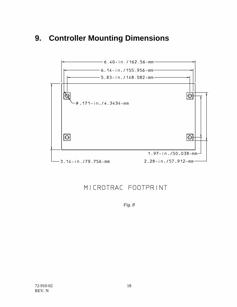
9. Controller Mounting Dimensions
Fig. 8
72-910-02
REV. N
19
10. Addendum: MicroTrac PC Board Replacement4
Disconnect input power cord from AC Mains Receptacle prior to opening the MicroTrac controller. With the input power disconnected, the MicroTrac LCD and LEDs will be off.
1. Remove the four screws that retain the front panel and remove it.
2. Unplug Bleed, Supply and Dose Terminal Blocks.
3. Using and insulated screw driver, remove 4 PCB mounting screws located at each corner of
the PCB assembly.
4. Remove the MicroTrac PCBA to be replaced from the enclosure. Note: the flow, water
meter and probe cables are still attached.
5. Install the new MicroTrac PCBA into the top enclosure. Ensure that the LCD, buttons and
LEDs are correctly aligned in the top enclosure.
6. Secure the new board with the 4 mounting screws located at each corner of the MicroTrac
PCB Assembly (PCBA).
7. Transfer the flow, water meter and probe cables from the MicroTrac PCBA being replaced to
the new PCBA. Ensure that connections match the silkscreen on the new MicroTrac PCBA.
8. Plug the Bleed, Supply and Dose Terminal Blocks into the new MicroTrac PCBA. Ensure
that connections match the silkscreen on the new PCBA.
9. With an ohm meter, check that the center conductor of the Supply Terminal Block is
connected to the ground terminal of the disconnected input power cord.
10. Set SW1 on the new MicroTrac PCBA to the same settings as the MicroTrac PCBA being
replaced.
11. Visually inspect all connections.
12. Use an ohm meter on the disconnected plug of the input power cord and check for low
resistances (less than 1 ohm) between Line to Line and line to ground.
13. Disconnect the meter, remove all tools and power the MicroTrac on. The display will the
splash screen and start menu will be shown.
4 Trained service personnel are required for all electrical connections. This product does not contain operator serviceable
parts.
72-910-02
REV. N
20
11. MICROtrac Factory Service Policy
Your MICROtrac controller is a state of the art microprocessor based controller. If you are experiencing a
problem with your Microtrac controller, first consult the troubleshooting guide in this manual. If the
problem cannot be resolved contact Technical Services for assistance.
PULSAFEEDER INC. (SPO)
27101 AIRPORT ROAD
PUNTA GORDA, FL 33982
941-575-3800
Trained technicians are available to help diagnose your controller or process problems.
All returns require a Return Authorization number to be issued by Pulsafeeder. Parts purchased to correct
a warranty issue may be credited after an examination of original parts by Pulsafeeder. Warranty parts
returned as defective which test good will be sent back freight collect. No credit will be issued on any
replacement electronic parts.
Any modifications or out-of-warranty repairs will be subject to associate parts and labor costs.
72-910-02
REV. N
21
EC Declaration of Conformity We, Pulsafeeder Inc., declare under sole responsibility that Microtrac equipment to which this declaration
relates is in sole conformity with relevant sections of the applicable EC standards and other normative
documents listed on this document. If changes are made to the product which is covered by this declaration
of conformity, the declaration of conformity is no longer valid.
- Radiated emissions EN 61326 - Harmonic current emissions (EN 61000-3-2-1995+A14:1998) - Voltage fluctuations and flicker (EN 61000-3-3: 1995) - Electrostatic Discharge Immunity Test (EN 61000-4-2:95) - Radiated immunity test (EN 61000-4-3:96) - Electrical Fast Transient/Burst Immunity Test (EN 61000-4-4:95) - Surge Immunity Test (EN 61000-4-5:95) - Immunity to conducted disturbances (EN 61000-4-6:96) - Power Frequency Magnetic Field Immunity Test (EN 61000-4-8:93) - Voltage Dips, Short Interruptions and Voltage Variations Immunity Tests (EN61000-4-11:1994) - 2002/96/EG (WEEE) compliant - RoHS compliant

72-910-02
REV. N
22
USA Pulsafeeder, Inc. 27101 Airport Road Punta Gorda, FL 33982 USA (941) 575-3800 www.pulsa.com
European Union (EU) PULSAFEEDER-Europe Via Kennedy, 12-20090 Segrate—Milano– Italy


![Huawei Enterprise Business [HD Edited] - · PDF fileHuawei Enterprise Business Portfolio ... OSN 38/1800OSN 6800OSN 8800 OSN 500 Metro 1000/500/100 OSN 2500/3500/7500/9500 RTN 910](https://img.pdfslide.us/doc/110x75/5a718a0a7f8b9ab1538ce6f5/huawei-enterprise-business-hd-edited-servnetwwwservnetinfbrhuaweienterprisebusinesspdfpdf.jpg)