Embed Size (px)
Citation preview

• Plug and Play Configurable
• No fan for better reliability
• Compact size
• Wide input voltage range :
9-45Vdc transient 60Vdc/100ms
16-80Vdc transient 100Vdc/100ms
• Reverse polarity protected
• Up to 4 independent outputs
• Serial/Parallel outputs
• EMI compliant with MIL-STD-461
• No load to full load operation
• Up to 88% efficiency
GPack Configurable Power Supply
For locations, phone, fax, E-Mail see back cover
2
GPack-800 Series
Gaia Converter FC15-062.06/15 Revision B©
4
Hi-RelGrade
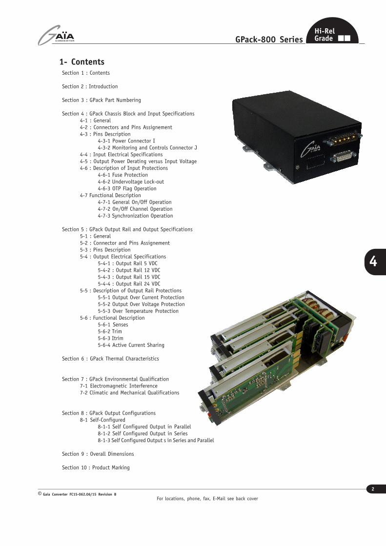
1- ContentsSection 1 : Contents
Section 2 : Introduction
Section 3 : GPack Part Numbering
Section 4 : GPack Chassis Block and Input Specifications4-1 : General4-2 : Connectors and Pins Assignement4-3 : Pins Description
4-3-1 Power Connector I4-3-2 Monitoring and Controls Connector J
4-4 : Input Electrical Specifications4-5 : Output Power Derating versus Input Voltage4-6 : Description of Input Protections
4-6-1 Fuse Protection4-6-2 Undervoltage Lock-out4-6-3 OTP Flag Operation
4-7 Functional Description4-7-1 General On/Off Operation4-7-2 On/Off Channel Operation4-7-3 Synchronization Operation
Section 5 : GPack Output Rail and Output Specifications5-1 : General5-2 : Connector and Pins Assignement5-3 : Pins Description5-4 : Output Electrical Specifications
5-4-1 : Output Rail 5 VDC5-4-2 : Output Rail 12 VDC5-4-3 : Output Rail 15 VDC5-4-4 : Output Rail 24 VDC
5-5 : Description of Output Rail Protections5-5-1 Output Over Current Protection5-5-2 Output Over Voltage Protection5-5-3 Over Temperature Protection
5-6 : Functional Description5-6-1 Senses5-6-2 Trim5-6-3 Itrim5-6-4 Active Current Sharing
Section 6 : GPack Thermal Characteristics
Section 7 : GPack Environmental Qualification7-1 Electromagnetic Interference7-2 Climatic and Mechanical Qualifications
Section 8 : GPack Output Configurations8-1 Self-Configured
8-1-1 Self Configured Output in Parallel8-1-2 Self Configured Output in Series8-1-3 Self Configured Output s in Series and Parallel
Section 9 : Overall Dimensions
Section 10 : Product Marking
For locations, phone, fax, E-Mail see back cover
3
GPack-800 Series
Gaia Converter FC15-062.06/15 Revision B©
4
Hi-RelGrade
2- Introduction
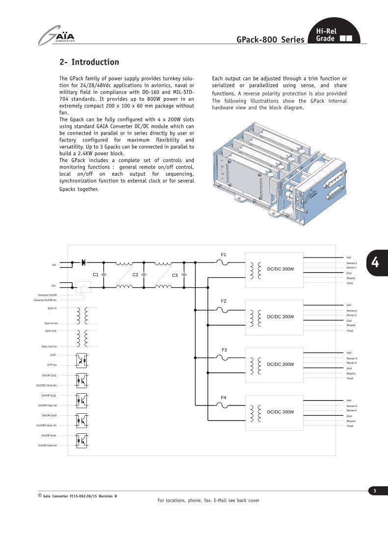
The GPack family of power supply provides turnkey solu-tion for 24/28/48Vdc applications in avionics, naval ormilitary field in compliance with DO-160 and MIL-STD-704 standards. It provides up to 800W power in anextremely compact 200 x 100 x 60 mm package withoutfan.The Gpack can be fully configured with 4 x 200W slotsusing standard GAIA Converter DC/DC module which canbe connected in parallel or in series directly by user orfactory configured for maximum flexibility andversatility. Up to 3 Gpacks can be connected in parallel tobuild a 2.4KW power block.The GPack includes a complete set of controls andmonitoring functions : general remote on/off control,local on/off on each output for sequencing,synchronization function to external clock or for several
Gpacks together.
Each output can be adjusted through a trim function orserialized or parallellized using sense, and share
functions. A reverse polarity protection is also providedThe following illustrations show the GPack internalhardware view and the block diagram.
C1 C2 C3
F1
DC/DC 200W
F2
F3
F4
Vo1
VinSense+1
On/Off Out1
On/Off1 Out1-rtn
On/Off Out2
On/Off Out2-rtn
Gin
OTP
OTP-rtn
General On/Off
General On/Off-rtn
Sync In
Sync In-rtn
Sync Out
Sync Out-rtn
On/Off Out3
On/Off3 Out1-rtn
On/Off Out4
On/Off Out4-rtn
Go1
Sense-1
Share1
Trim1
DC/DC 200W
Vo2
Sense+2
Go2
Sense-2
Share2
Trim2
DC/DC 200W
Vo3
Sense+3
Go3
Sense-3
Share3
Trim3
DC/DC 200W
Vo4
Sense+4
Go4
Sense-4
Share4
Trim4
For locations, phone, fax, E-Mail see back cover
4
GPack-800 Series
Gaia Converter FC15-062.06/15 Revision B©
4
Hi-RelGrade
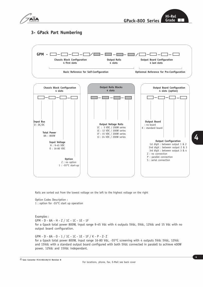
3- GPack Part Numbering
Chassis Block Configuration4 slots
Input BusD : DC/DC
GPM -
Chassis Block Configuration4 first slots
Output Rails4 slots
Output Board Configuration4 last slots
Output Rails Blocks4 slots
Total Power8A : 800W
Input VoltageH : 9-45 VDCO : 16-80 VDC
OptionZ : no option
1 : -55°C start-up
Output Board Configuration4 slots (option)
Output Board : no boardK : standard board
Output Configuration1st digit : between output 1 & 22nd digit : between output 2 & 33rd digit : between output 3 & 4
Z : no connectionP : parallel connectionS : serial connection
Output Voltage Rails1C : 5 VDC / 200W series1E : 12 VDC / 200W series1F : 15 VDC / 200W series1I : 24 VDC / 200W series
Rails are sorted out from the lowest voltage on the left to the highest voltage on the right
Option Codes Description :1 : option for -55°C start up operation
Examples :GPM - D - 8A - H - Z / 1C - 1C - 1E - 1Ffor a Gpack total power 800W, input range 9-45 Vdc with 4 outputs 5Vdc, 5Vdc, 12Vdc and 15 Vdc with nooutput board configuration.
GPM - D - 8A - O - 1 / 1C - 1C - 1E - 1F / K - P - Z- Zfor a Gpack total power 800W, input range 16-80 Vdc, -55°C screening with 4 outputs 5Vdc 5Vdc, 12Vdcand 15Vdc with a standard output board configured with both 5Vdc connected in paralell to achieve 400Wpower, 12Vdc and 15Vdc independant.
Basic Reference for Self-Configuration Optionnal Reference for Pre-Configuration
For locations, phone, fax, E-Mail see back cover
5
GPack-800 Series
Gaia Converter FC15-062.06/15 Revision B©
4
Hi-RelGrade
4- GPack Chassis Block and Input Specifications
4-1 General
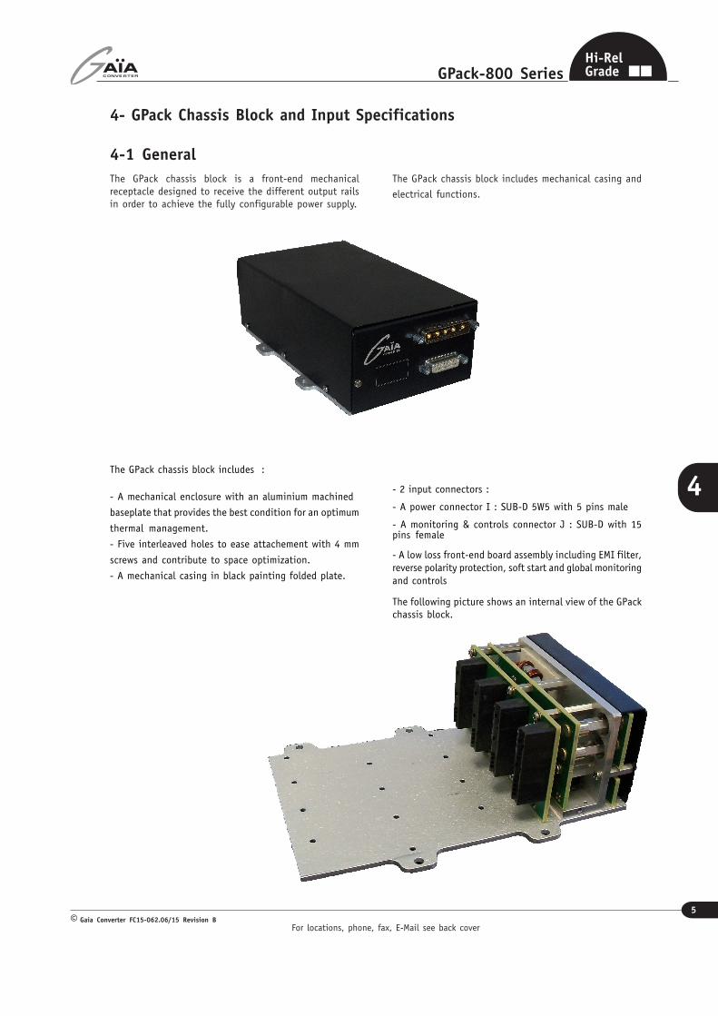
The GPack chassis block is a front-end mechanicalreceptacle designed to receive the different output railsin order to achieve the fully configurable power supply.
The GPack chassis block includes mechanical casing and
electrical functions.
The GPack chassis block includes :
- A mechanical enclosure with an aluminium machined
baseplate that provides the best condition for an optimum
thermal management.
- Five interleaved holes to ease attachement with 4 mm
screws and contribute to space optimization.
- A mechanical casing in black painting folded plate.
- 2 input connectors :
- A power connector I : SUB-D 5W5 with 5 pins male
- A monitoring & controls connector J : SUB-D with 15pins female
- A low loss front-end board assembly including EMI filter,reverse polarity protection, soft start and global monitoringand controls
The following picture shows an internal view of the GPackchassis block.
For locations, phone, fax, E-Mail see back cover
6
GPack-800 Series
Gaia Converter FC15-062.06/15 Revision B©
4
Hi-RelGrade
4- Chassis Block and Input Specifications (continued)
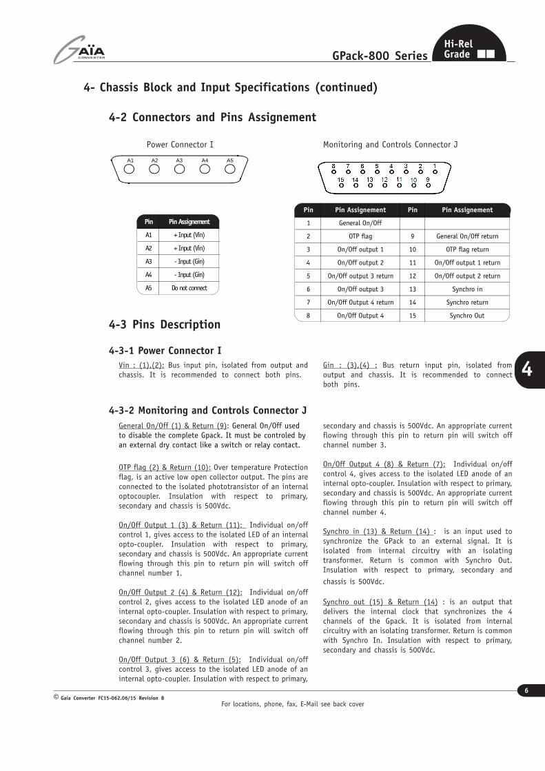
4-2 Connectors and Pins Assignement
Pin Pin Assignement Pin Pin Assignement
1 General On/Off
2 OTP flag 9 General On/Off return
3 On/Off output 1 10 OTP flag return
4 On/Off output 2 11 On/Off output 1 return
5 On/Off output 3 return 12 On/Off output 2 return
6 On/Off output 3 13 Synchro in
7 On/Off Output 4 return 14 Synchro return
8 On/Off Output 4 15 Synchro Out
Pin Pin Assignement
A1 + Input (Vin)
A2 + Input (Vin)
A3 - Input (Gin)
A4 - Input (Gin)
A5 Do not connect
4-3 Pins Description
4-3-1 Power Connector I
4-3-2 Monitoring and Controls Connector J
Power Connector I Monitoring and Controls Connector J
A5A4A3A2A1
Gin : (3),(4) : Bus return input pin, isolated fromoutput and chassis. It is recommended to connectboth pins.
Vin : (1),(2): Bus input pin, isolated from output andchassis. It is recommended to connect both pins.
General On/Off (1) & Return (9): General On/Off usedto disable the complete Gpack. It must be controled byan external dry contact like a switch or relay contact.
OTP flag (2) & Return (10): Over temperature Protectionflag, is an active low open collector output. The pins areconnected to the isolated phototransistor of an internaloptocoupler. Insulation with respect to primary,secondary and chassis is 500Vdc.
On/Off Output 1 (3) & Return (11): Individual on/offcontrol 1, gives access to the isolated LED of an internalopto-coupler. Insulation with respect to primary,secondary and chassis is 500Vdc. An appropriate currentflowing through this pin to return pin will switch offchannel number 1.
On/Off Output 2 (4) & Return (12): Individual on/offcontrol 2, gives access to the isolated LED anode of aninternal opto-coupler. Insulation with respect to primary,secondary and chassis is 500Vdc. An appropriate currentflowing through this pin to return pin will switch offchannel number 2.
On/Off Output 3 (6) & Return (5): Individual on/offcontrol 3, gives access to the isolated LED anode of aninternal opto-coupler. Insulation with respect to primary,
secondary and chassis is 500Vdc. An appropriate currentflowing through this pin to return pin will switch offchannel number 3.
On/Off Output 4 (8) & Return (7): Individual on/offcontrol 4, gives access to the isolated LED anode of aninternal opto-coupler. Insulation with respect to primary,secondary and chassis is 500Vdc. An appropriate currentflowing through this pin to return pin will switch offchannel number 4.
Synchro in (13) & Return (14) : is an input used tosynchronize the GPack to an external signal. It isisolated from internal circuitry with an isolatingtransformer. Return is common with Synchro Out.Insulation with respect to primary, secondary and
chassis is 500Vdc.
Synchro out (15) & Return (14) : is an output thatdelivers the internal clock that synchronizes the 4channels of the Gpack. It is isolated from internalcircuitry with an isolating transformer. Return is commonwith Synchro In. Insulation with respect to primary,secondary and chassis is 500Vdc.
For locations, phone, fax, E-Mail see back cover
7
GPack-800 Series
Gaia Converter FC15-062.06/15 Revision B©
4
Hi-RelGrade
4- Chassis Block and Input Specifications (Continued)
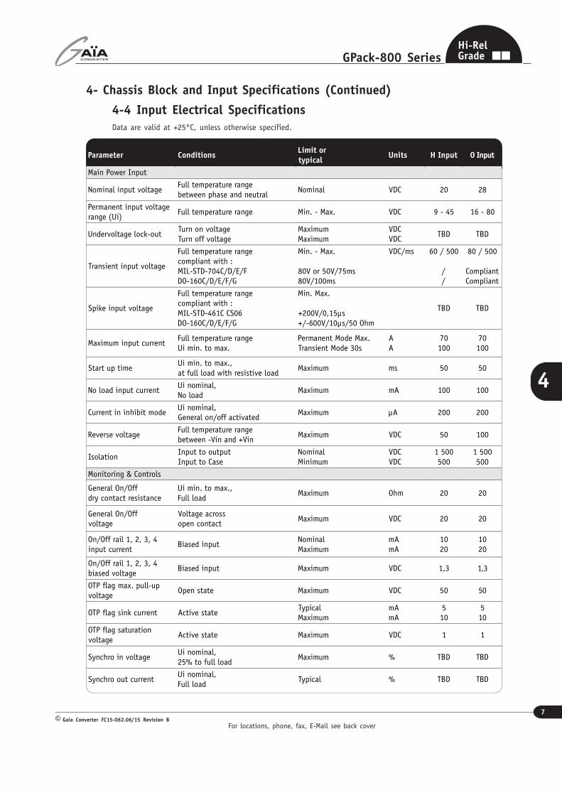
4-4 Input Electrical SpecificationsData are valid at +25°C, unless otherwise specified.
Parameter ConditionsLimit ortypical
Units H Input O Input
Main Power Input
Nominal input voltageFull temperature rangebetween phase and neutral
Nominal VDC 20 28
Permanent input voltagerange (Ui)
Full temperature range Min. - Max. VDC 9 - 45 16 - 80
Undervoltage lock-outTurn on voltageTurn off voltage
MaximumMaximum
VDCVDC
TBD TBD
Transient input voltage
Full temperature rangecompliant with :MIL-STD-704C/D/E/FDO-160C/D/E/F/G
Min. - Max.
80V or 50V/75ms80V/100ms
VDC/ms 60 / 500
//
80 / 500
CompliantCompliant
Spike input voltage
Full temperature rangecompliant with :MIL-STD-461C CS06DO-160C/D/E/F/G
Min. Max.
+200V/0,15µs+/-600V/10µs/50 Ohm
TBD TBD
Maximum input currentFull temperature rangeUi min. to max.
Permanent Mode Max.Transient Mode 30s
AA
70100
70100
Start up timeUi min. to max.,at full load with resistive load
Maximum ms 50 50
No load input currentUi nominal,No load
Maximum mA 100 100
Current in inhibit modeUi nominal,General on/off activated
Maximum µA 200 200
Reverse voltageFull temperature rangebetween -Vin and +Vin
Maximum VDC 50 100
IsolationInput to outputInput to Case
NominalMinimum
VDCVDC
1 500500
1 500500
Monitoring & Controls
General On/Offdry contact resistance
Ui min. to max.,Full load
Maximum Ohm 20 20
General On/Offvoltage
Voltage acrossopen contact
Maximum VDC 20 20
On/Off rail 1, 2, 3, 4input current
Biased inputNominalMaximum
mAmA
1020
1020
On/Off rail 1, 2, 3, 4biased voltage
Biased input Maximum VDC 1,3 1,3
OTP flag max. pull-upvoltage
Open state Maximum VDC 50 50
OTP flag sink current Active stateTypicalMaximum
mAmA
510
510
OTP flag saturationvoltage
Active state Maximum VDC 1 1
Synchro in voltageUi nominal,25% to full load
Maximum % TBD TBD
Synchro out currentUi nominal,Full load
Typical % TBD TBD
For locations, phone, fax, E-Mail see back cover
8
GPack-800 Series
Gaia Converter FC15-062.06/15 Revision B©
4
Hi-RelGrade
4- Chassis Block and Input Specifications (Continued)
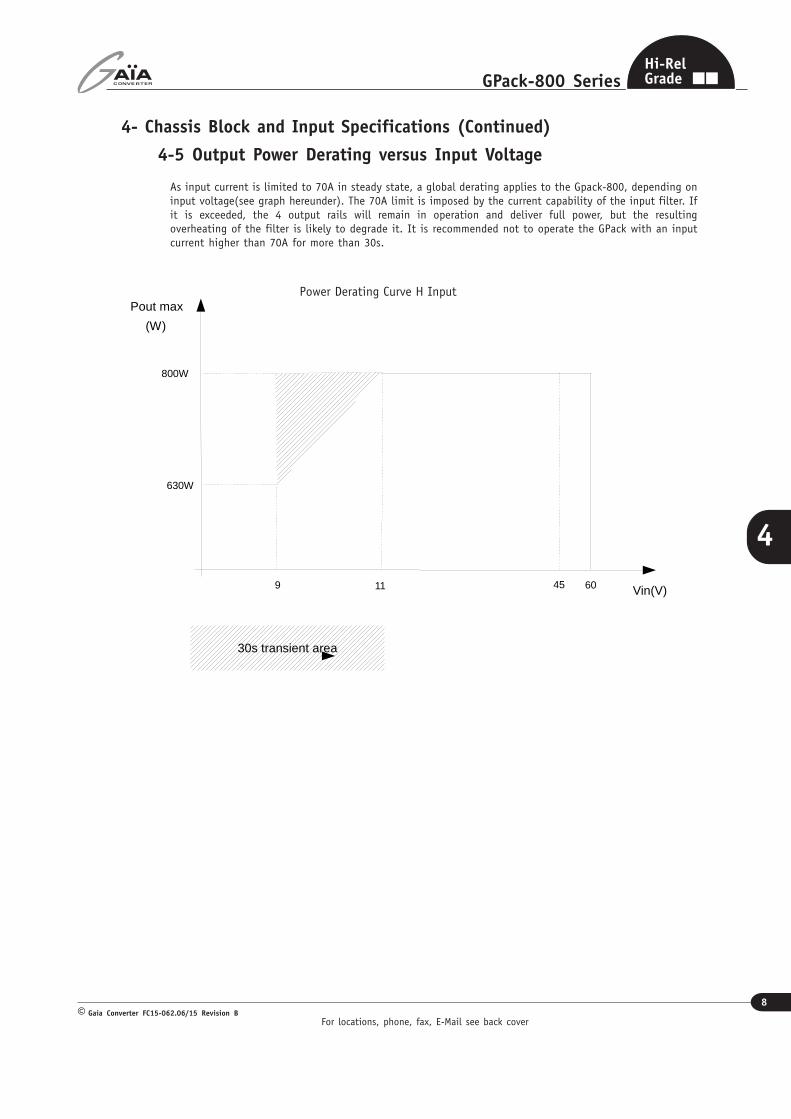
4-5 Output Power Derating versus Input Voltage
As input current is limited to 70A in steady state, a global derating applies to the Gpack-800, depending oninput voltage(see graph hereunder). The 70A limit is imposed by the current capability of the input filter. Ifit is exceeded, the 4 output rails will remain in operation and deliver full power, but the resultingoverheating of the filter is likely to degrade it. It is recommended not to operate the GPack with an inputcurrent higher than 70A for more than 30s.
Vin(V)
Pout max
(W)
9 11
800W
630W
45 60
30s transient area
Power Derating Curve H Input
For locations, phone, fax, E-Mail see back cover
9
GPack-800 Series
Gaia Converter FC15-062.06/15 Revision B©
4
Hi-RelGrade
4- Input Specifications (Continued)
4-6 Description of Input Protections
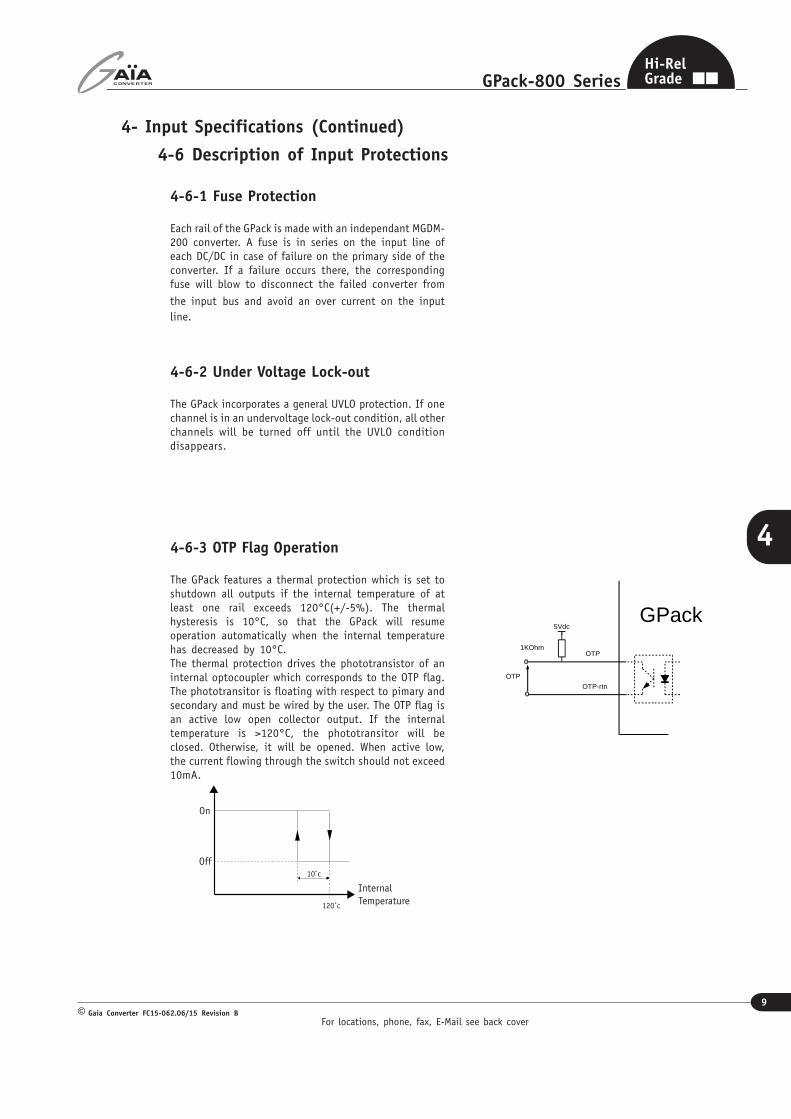
4-6-3 OTP Flag Operation
The GPack features a thermal protection which is set toshutdown all outputs if the internal temperature of atleast one rail exceeds 120°C(+/-5%). The thermalhysteresis is 10°C, so that the GPack will resumeoperation automatically when the internal temperaturehas decreased by 10°C.The thermal protection drives the phototransistor of aninternal optocoupler which corresponds to the OTP flag.The phototransitor is floating with respect to pimary andsecondary and must be wired by the user. The OTP flag isan active low open collector output. If the internaltemperature is >120°C, the phototransitor will beclosed. Otherwise, it will be opened. When active low,the current flowing through the switch should not exceed10mA.
OTP
5Vdc
1KOhm
GPack
OTP-rtn
OTP
4-6-2 Under Voltage Lock-out
The GPack incorporates a general UVLO protection. If onechannel is in an undervoltage lock-out condition, all otherchannels will be turned off until the UVLO conditiondisappears.
Internal Temperature
On
120˚c
Off10˚c
4-6-1 Fuse Protection
Each rail of the GPack is made with an independant MGDM-200 converter. A fuse is in series on the input line ofeach DC/DC in case of failure on the primary side of theconverter. If a failure occurs there, the correspondingfuse will blow to disconnect the failed converter from
the input bus and avoid an over current on the inputline.
For locations, phone, fax, E-Mail see back cover
10
GPack-800 Series
Gaia Converter FC15-062.06/15 Revision B©
4
Hi-RelGrade
4- Chassis Block and Input Specifications (Continued)
4-7 Functional Description
Switch 1On/Off control
GPackGeneral On/Off
General On/Off-rtn
Sw 1On/Off control
5Vdc
390 Ohm
GPack
On/Off x
On/Off x-Rtn
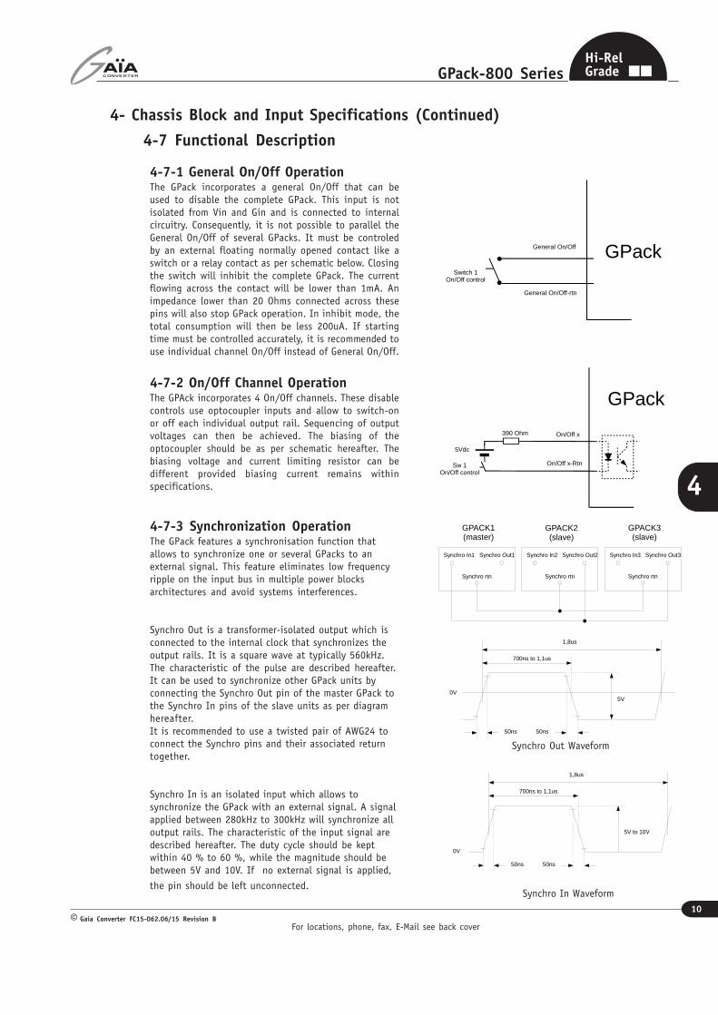
4-7-1 General On/Off OperationThe GPack incorporates a general On/Off that can beused to disable the complete GPack. This input is notisolated from Vin and Gin and is connected to internalcircuitry. Consequently, it is not possible to parallel theGeneral On/Off of several GPacks. It must be controledby an external floating normally opened contact like aswitch or a relay contact as per schematic below. Closingthe switch will inhibit the complete GPack. The currentflowing across the contact will be lower than 1mA. Animpedance lower than 20 Ohms connected across thesepins will also stop GPack operation. In inhibit mode, thetotal consumption will then be less 200uA. If startingtime must be controlled accurately, it is recommended touse individual channel On/Off instead of General On/Off.
4-7-2 On/Off Channel OperationThe GPAck incorporates 4 On/Off channels. These disablecontrols use optocoupler inputs and allow to switch-onor off each individual output rail. Sequencing of outputvoltages can then be achieved. The biasing of theoptocoupler should be as per schematic hereafter. Thebiasing voltage and current limiting resistor can bedifferent provided biasing current remains withinspecifications.
4-7-3 Synchronization OperationThe GPack features a synchronisation function thatallows to synchronize one or several GPacks to anexternal signal. This feature eliminates low frequencyripple on the input bus in multiple power blocksarchitectures and avoid systems interferences.
Synchro Out is a transformer-isolated output which isconnected to the internal clock that synchronizes theoutput rails. It is a square wave at typically 560kHz.The characteristic of the pulse are described hereafter.It can be used to synchronize other GPack units byconnecting the Synchro Out pin of the master GPack tothe Synchro In pins of the slave units as per diagramhereafter.It is recommended to use a twisted pair of AWG24 toconnect the Synchro pins and their associated returntogether.
Synchro In is an isolated input which allows tosynchronize the GPack with an external signal. A signalapplied between 280kHz to 300kHz will synchronize alloutput rails. The characteristic of the input signal aredescribed hereafter. The duty cycle should be keptwithin 40 % to 60 %, while the magnitude should bebetween 5V and 10V. If no external signal is applied,
the pin should be left unconnected.
50ns 50ns
0V
700ns to 1,1us
1,8us
5V
Synchro In Waveform
Synchro Out Waveform
Synchro In1
Synchro rtn
GPACK1(master)
Synchro Out1 Synchro In2
Synchro rtn
Synchro Out2 Synchro In3
Synchro rtn
Synchro Out3
GPACK2(slave)
GPACK3(slave)
50ns 50ns
0V
700ns to 1,1us
1,8us
5V to 10V
For locations, phone, fax, E-Mail see back cover
11
GPack-800 Series
Gaia Converter FC15-062.06/15 Revision B©
4
Hi-RelGrade
5- GPack Output Rail and Output Specifications
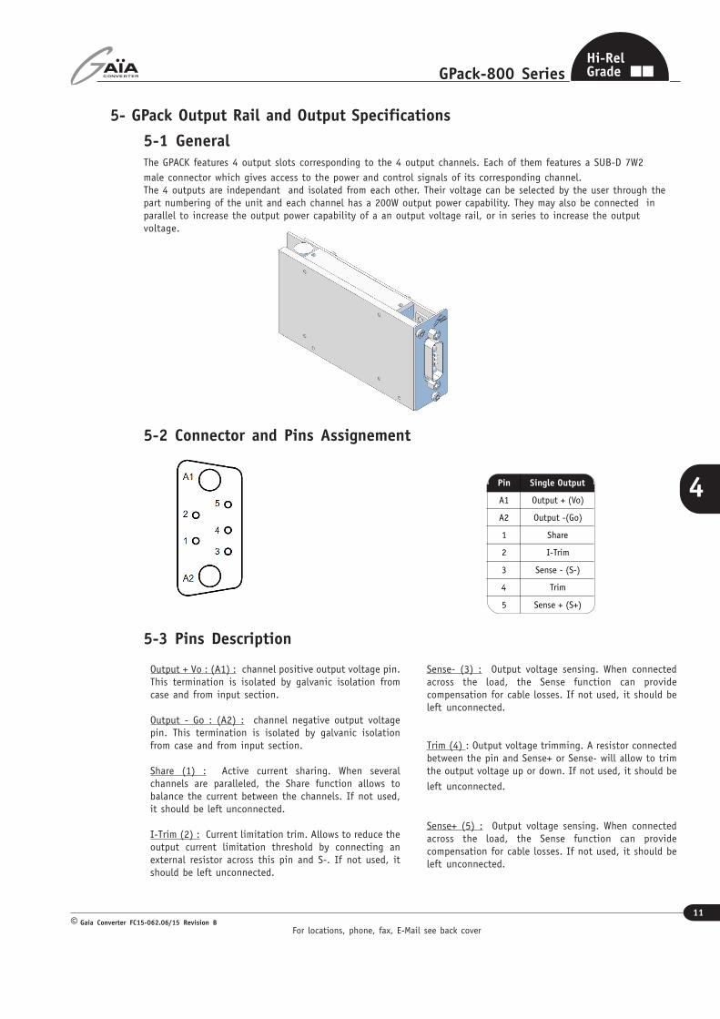
5-1 GeneralThe GPACK features 4 output slots corresponding to the 4 output channels. Each of them features a SUB-D 7W2
male connector which gives access to the power and control signals of its corresponding channel.The 4 outputs are independant and isolated from each other. Their voltage can be selected by the user through thepart numbering of the unit and each channel has a 200W output power capability. They may also be connected inparallel to increase the output power capability of a an output voltage rail, or in series to increase the outputvoltage.
Pin Single Output
A1 Output + (Vo)
A2 Output -(Go)
1 Share
2 I-Trim
3 Sense - (S-)
4 Trim
5 Sense + (S+)
5-2 Connector and Pins Assignement
5-3 Pins Description
Output + Vo : (A1) : channel positive output voltage pin.This termination is isolated by galvanic isolation fromcase and from input section.
Output - Go : (A2) : channel negative output voltagepin. This termination is isolated by galvanic isolationfrom case and from input section.
Share (1) : Active current sharing. When severalchannels are paralleled, the Share function allows tobalance the current between the channels. If not used,it should be left unconnected.
I-Trim (2) : Current limitation trim. Allows to reduce theoutput current limitation threshold by connecting anexternal resistor across this pin and S-. If not used, itshould be left unconnected.
Sense- (3) : Output voltage sensing. When connectedacross the load, the Sense function can providecompensation for cable losses. If not used, it should beleft unconnected.
Trim (4) : Output voltage trimming. A resistor connectedbetween the pin and Sense+ or Sense- will allow to trimthe output voltage up or down. If not used, it should be
left unconnected.
Sense+ (5) : Output voltage sensing. When connectedacross the load, the Sense function can providecompensation for cable losses. If not used, it should beleft unconnected.

For locations, phone, fax, E-Mail see back cover
12
GPack-800 Series
Gaia Converter FC15-062.06/15 Revision B©
4
Hi-RelGrade
5- GPack Output Rail and Output Specifications (Continued)
5-4 Electrical Specifications
5-4-1 Output Rail 5 VDC
Data are valid at +25°C, unless otherwise specified.
Parameter ConditionsLimit ortypical
Units H Input O Input
Output
Output voltage
Full temperature range
Ui min. to max.,Full load
Nominal VDC 5 5
Set point accuracyUi nominal
75% load
Temperature 25°CUi nominal,75% load
% +/-2 +/-2
Output powerFull temperature rangeUi min. to max.
Maximum W 175 175
Output currentFull temperature rangeUi min. to max.
Maximum A 35 35
Ripple output voltageUi nominal,Full loadBW=20MHz
Maximum mVpp 100 100
Line + Load regulationUi min. to max.,0% to full load
Maximum % +/-1 +/-1
Output voltage trimrange
As function ofoutput voltage
MinimumMaximum
%%
10110
10110
Switching frequencyUi min. to max.0% load to full load
Nominal, fixed KHz 270 270
Isolation Input to output Nominal VDC 1 500 1 500
Maximum admissiblecapacitive load
Ui nominal, 400HzFull load
Maximum per output µF TBD TBD

For locations, phone, fax, E-Mail see back cover
13
GPack-800 Series
Gaia Converter FC15-062.06/15 Revision B©
4
Hi-RelGrade
5- GPack Output Rail and Output Specifications (Continued)
5-4 Electrical Specifications
5-4-2 Output Rail 12 VDC
Data are valid at +25°C, unless otherwise specified.
Parameter ConditionsLimit ortypical
Units H Input O Input
Output
Output voltageFull temperature rangeUi min. to max.,
Full load
Nominal VDC 12 12
Set point accuracyUi nominal
75% load
Temperature 25°CUi nominal,75% load
% +/-2 +/-2
Output powerFull temperature rangeUi min. to max.
Maximum W 200 200
Output currentFull temperature rangeUi min. to max.
Maximum A 16,5 16,5
Ripple output voltageUi nominal,Full loadBW=20MHz
Maximum mVpp 250 250
Line + Load regulationUi min. to max.,0% to full load
Maximum % +/-1 +/-1
Output voltage trimrange
As function ofoutput voltage
MinimumMaximum
%%
10110
10110
Switching frequencyUi min. to max.0% load to full load
Nominal, fixed KHz 270 270
Isolation Input to output Nominal VDC 1 500 1 500
Maximum admissiblecapacitive load
Ui nominal, 400HzFull load
Maximum per output µF TBD TBD
For locations, phone, fax, E-Mail see back cover
14
GPack-800 Series
Gaia Converter FC15-062.06/15 Revision B©
4
Hi-RelGrade
5- GPack Output Rail and Output Specifications (Continued)
5-4 Electrical Specifications
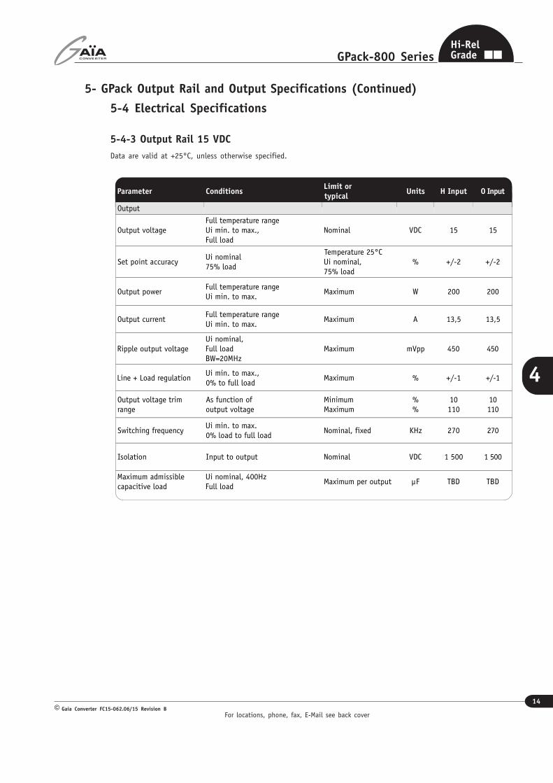
5-4-3 Output Rail 15 VDC
Data are valid at +25°C, unless otherwise specified.
Parameter ConditionsLimit ortypical
Units H Input O Input
Output
Output voltageFull temperature rangeUi min. to max.,
Full load
Nominal VDC 15 15
Set point accuracyUi nominal
75% load
Temperature 25°CUi nominal,75% load
% +/-2 +/-2
Output powerFull temperature rangeUi min. to max.
Maximum W 200 200
Output currentFull temperature rangeUi min. to max.
Maximum A 13,5 13,5
Ripple output voltageUi nominal,Full loadBW=20MHz
Maximum mVpp 450 450
Line + Load regulationUi min. to max.,0% to full load
Maximum % +/-1 +/-1
Output voltage trimrange
As function ofoutput voltage
MinimumMaximum
%%
10110
10110
Switching frequencyUi min. to max.0% load to full load
Nominal, fixed KHz 270 270
Isolation Input to output Nominal VDC 1 500 1 500
Maximum admissiblecapacitive load
Ui nominal, 400HzFull load
Maximum per output µF TBD TBD

For locations, phone, fax, E-Mail see back cover
15
GPack-800 Series
Gaia Converter FC15-062.06/15 Revision B©
4
Hi-RelGrade
5- GPack Output Rail and Output Specifications (Continued)
5-4 Electrical Specifications
5-4-4 Output Rail 24 VDC
Data are valid at +25°C, unless otherwise specified.
Parameter ConditionsLimit ortypical
Units H Input O Input
Output
Output voltageFull temperature rangeUi min. to max.,
Full load
Nominal VDC 24 24
Set point accuracyUi nominal
75% load
Temperature 25°CUi nominal,75% load
% +/-2 +/-2
Output powerFull temperature rangeUi min. to max.
Maximum W 200 200
Output currentFull temperature rangeUi min. to max.
Maximum A 8,5 8,5
Ripple output voltageUi nominal,Full loadBW=20MHz
Maximum mVpp 500 500
Line + Load regulationUi min. to max.,0% to full load
Maximum % +/-1 +/-1
Output voltage trimrange
As function ofoutput voltage
MinimumMaximum
%%
10110
10110
Switching frequencyUi min. to max.0% load to full load
Nominal, fixed KHz 270 270
Isolation Input to output Nominal VDC 1 500 1 500
Maximum admissiblecapacitive load
Ui nominal, 400HzFull load
Maximum per output µF TBD TBD
For locations, phone, fax, E-Mail see back cover
16
GPack-800 Series
Gaia Converter FC15-062.06/15 Revision B©
4
Hi-RelGrade
5- GPack Output Rail and Output Specifications (continued)
5-5 Description of Output Rail Protections
5-5-2 Output Overvoltage Protection (OVP)Each rail has an internal overvoltage protection circuit thatmonitors the voltage across the output power terminals.It will clamp the output voltage at 130 % of its nominalvalue in case of failure in the regulation loop.
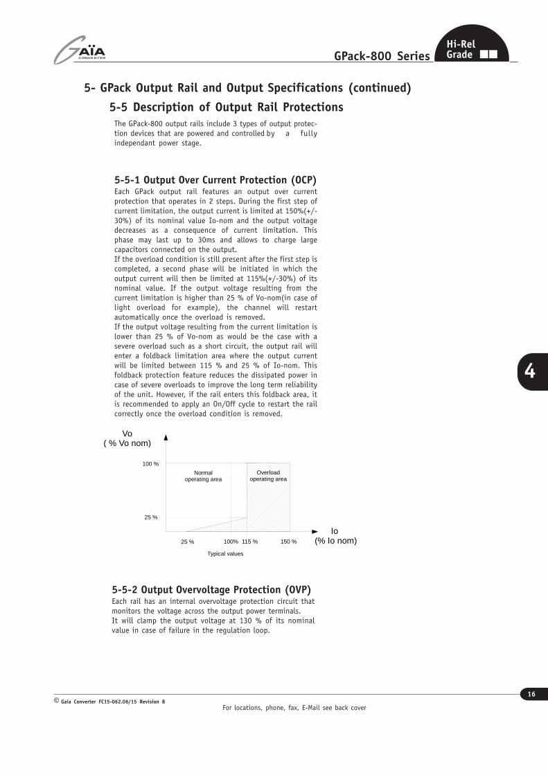
The GPack-800 output rails include 3 types of output protec-tion devices that are powered and controlled by a fullyindependant power stage.
5-5-1 Output Over Current Protection (OCP)Each GPack output rail features an output over currentprotection that operates in 2 steps. During the first step ofcurrent limitation, the output current is limited at 150%(+/-30%) of its nominal value Io-nom and the output voltagedecreases as a consequence of current limitation. Thisphase may last up to 30ms and allows to charge largecapacitors connected on the output.If the overload condition is still present after the first step iscompleted, a second phase will be initiated in which theoutput current will then be limited at 115%(+/-30%) of itsnominal value. If the output voltage resulting from thecurrent limitation is higher than 25 % of Vo-nom(in case oflight overload for example), the channel will restartautomatically once the overload is removed.If the output voltage resulting from the current limitation islower than 25 % of Vo-nom as would be the case with asevere overload such as a short circuit, the output rail willenter a foldback limitation area where the output currentwill be limited between 115 % and 25 % of Io-nom. Thisfoldback protection feature reduces the dissipated power incase of severe overloads to improve the long term reliabilityof the unit. However, if the rail enters this foldback area, itis recommended to apply an On/Off cycle to restart the railcorrectly once the overload condition is removed.
Io (% Io nom)
Vo( % Vo nom)
115 %
150 %100%25 %
100 %
25 %
Typical values
Normal operating area
Overload operating area
For locations, phone, fax, E-Mail see back cover
17
GPack-800 Series
Gaia Converter FC15-062.06/15 Revision B©
4
Hi-RelGrade
5- GPack Output Rail and Output Specifications (continued)
5-6 Functional Description
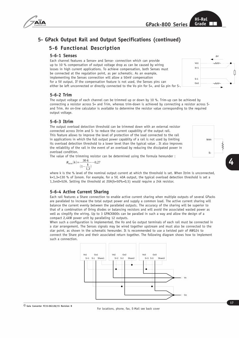
5-6-1 SensesEach channel features a Sense+ and Sense- connection which can provideup to 10 % compensation of output voltage drop as can be caused by wiringlosses in high current applications. To achieve compensation, both Senses mustbe connected at the regulation point, as per schematic. As an example,implementing the Senses connection will allow a 50mV compensationfor a 5V output. If the compensation feature is not used, the Senses pins caneither be left unconnected or directly connected to the Vo pin for S+, and Go pin for S-.
5-6-2 TrimThe output voltage of each channel can be trimmed up or down by 10 %. Trim-up can be achieved byconnecting a resistor across S+ and Trim, whereas trim-down is achieved by connecting a resistor across S-and Trim. An on-line calculator is available to determine the resistor value corresponding to the requiredoutput voltage.
5-6-3 ItrimThe output overload detection threshold can be trimmed down with an external resistorconnected across Itrim and S- to reduce the current capability of the output rail.This feature allows to improve the level of protection of the load connected to the railin applications in which the full output power capablity of a rail is not used by limitingits overload detection threshold to a lower level than the typical value . It also improvesthe reliability of the rail in the event of an overload by reducing the dissipated power inoverload condition.The value of the trimming resistor can be determined using the formula hereunder :
where k is the % level of the nominal output current at which the threshold is set. When Itrim is unconnected,k=1,3=130 % of Ionom. For example, for a 5V, 40A output, the typical overload detection threshold is set a1,3x40=52A. Setting the threshold at 20A(k=50%=0,5) would require a 24k resistor.
5-6-4 Active Current SharingEach rail features a Share connection to enable active current sharing when multiple outputs of several GPacksare paralleled to increase the total output power and supply a common load. The active current sharing willbalance the current evenly between the paralleled outputs. The accuracy of the sharing will be superior tothat of a combination of Oring diodes or balancing resistors and will avoid the associated wasted power aswell as simplify the wiring. Up to 3 GPACK800s can be paralled in such a way and allow the design of acompact 2,4kW power unit by paralleling 12 outputs.When such a configuration is implemented, the Vo and Go output terminals of each rail must be connected ina star arrangement. The Senses signals may be wired together upstream and must also be connected to thestar point, as shown in the schematic hereunder. It is recommended to use a twisted pair of AWG24 toconnect the Share pins and their associated return together. The following diagram shows how to implementsuch a connection.
RItrim
(k )=30⋅k
(1�k
1,3)�0,27
Vo1
Go1
S+1
S-1
∆V
Itrim
S-
Vo2 Go2
S+2 S-2 Share2
Vo
Go
Vo1 Go1
S+1 S-1 Share1
Vo3 Go3
S+3 S-3 Share3
For locations, phone, fax, E-Mail see back cover
18
GPack-800 Series
Gaia Converter FC15-062.06/15 Revision B©
4
Hi-RelGrade
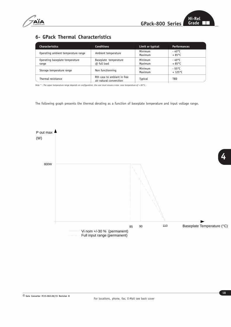
6- GPack Thermal Characteristics
Note * : The upper temperature range depends on configuration, the user must assure a max. case temperature of + 85°C.
The following graph presents the thermal derating as a function of baseplate temperature and input voltage range.
Characteristics Conditions Limit or typical Performances
Operating ambient temperature range Ambient temperatureMinimum
Maximum
- 40°C+ 85°C
Operating baseplate temperaturerange
Baseplate temperature@ full load
MinimumMaximum
- 40°C+ 85°C
Storage temperature range Non functionningMinimumMaximum
- 55°C+ 125°C
Thermal resistanceRth case to ambiant in freeair natural converction
Typical TBD
Baseplate Temperature (°C)
P out max
(W)
800W
90 11085
Vi nom +/-30 % (permanent)Full input range (permanent)
For locations, phone, fax, E-Mail see back cover
19
GPack-800 Series
Gaia Converter FC15-062.06/15 Revision B©
4
Hi-RelGrade
7- GPack Environmental Qualification
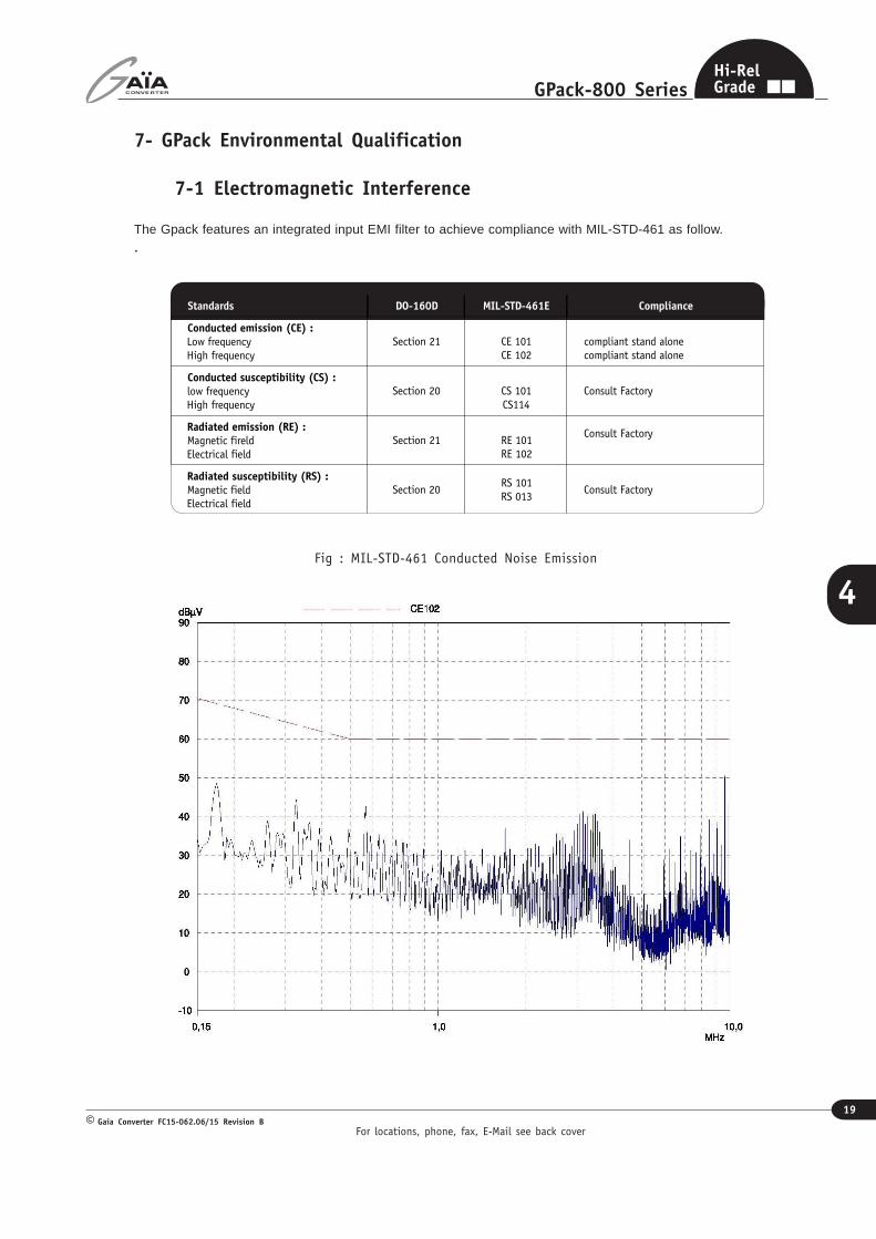
7-1 Electromagnetic Interference
The Gpack features an integrated input EMI filter to achieve compliance with MIL-STD-461 as follow..
Standards DO-160D MIL-STD-461E Compliance
Conducted emission (CE) :Low frequency
High frequency
Section 21 CE 101
CE 102
compliant stand alone
compliant stand alone
Conducted susceptibility (CS) :low frequency
High frequency
Section 20 CS 101
CS114
Consult Factory
Radiated emission (RE) :Magnetic fireld
Electrical field
Section 21 RE 101
RE 102
Consult Factory
Radiated susceptibility (RS) :Magnetic field
Electrical field
Section 20RS 101
RS 013Consult Factory
Fig : MIL-STD-461 Conducted Noise Emission
For locations, phone, fax, E-Mail see back cover
20
GPack-800 Series
Gaia Converter FC15-062.06/15 Revision B©
4
Hi-RelGrade
7- GPack Environmental Qualification (continued)
7-2 Climatic and Mechanical QualificationsThe GPack has been subjected to the following environmental qualifications.
Characteristics Conditions Severity Test procedure
Climatic Qualifications
Life at high
temperature
Duration
Temperature / status of unit TBDMIL-STD-202G
Method 108A
Altitude
Altitude level C
Duration
Climb up
Stabilization
Status of unit
TBDMIL-STD-810E
Method 500.3
Humidity cyclic
Number of cycle
Cycle duration
Relative humidity variation
Temperature variation
Status of unit
TBDMIL-STD-810E
Method 507.3
Humidity steady
Damp heat
Temperature
Duration
Status of unit
TBDMIL-STD-202G
Method 103B
Salt atmosphere
Temperature
Concentration NaCl
Duration
Status of unit
TBDMIL-STD-810E
Method 509.3
Temperature
cycling
Number of cycles
Temperature change
Transfert time
Steady state time
Status of unit
TBDMIL-STD-202A
Method 102A
Temperature
shock
Number of shocks
Temperature change
Transfert time
Steady state time
Status of unit
TBDMIL-STD-202G
Method 107G
Mechanical Qualifications
Vibration
(Sinusoidal)
Number of cycles
Frequency / amplitude
Frequency / acceleration
Duration
Status of unit
TBDMIL-STD-810D
Method 514.3
Shock
(Half sinus)
Number of shocks
Peak acceleration
Duration
Shock form
Status of unit
TBDMIL-STD-810D
Method 516.3
Bump
(Half sinus)
Number of bumps
Peak acceleration
Duration
Status of unit
TBDMIL-STD-810D
Method 516.3
For locations, phone, fax, E-Mail see back cover
21
GPack-800 Series
Gaia Converter FC15-062.06/15 Revision B©
4
Hi-RelGrade
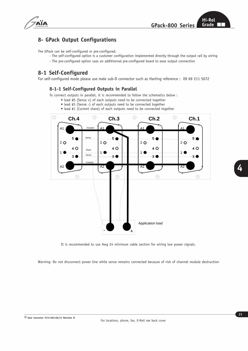
8- GPack Output Configurations
The GPack can be self-configured or pre-configured.- The self-configured option is a customer configuration implemented directly through the output rail by wiring
- The pre-configured option uses an additionnal pre-configured board to ease output connection
8-1 Self-ConfiguredFor self-configured mode please use male sub-D connector such as Harting reference : 09 69 211 5072
8-1-1 Self-Configured Outputs in ParallelTo connect outputs in parallel, it is recommended to follow the schematics below :
• lead #5 (Sense +) of each outputs need to be connected together• lead #3 (Sense -) of each outputs need to be connected together• lead #1 (Current share) of each outputs need to be connected together
It is recommended to use Awg 24 minimum cable section for wiring low power signals.
Warning: Do not disconnect power line while sense remains connected because of risk of channel module destruction
+-Application load
3
4
5
A1
2
1
A2
3
4
5
3
4
5
A1
2
1
A2
3
4
5
3
4
5
A1
2
1
A2
3
4
5
3
4
5
A1
2
1
A2
3
4
5
Ch.4 Ch.3 Ch.2 Ch.1
POWER
POWER
Sense
Sense
Share
For locations, phone, fax, E-Mail see back cover
22
GPack-800 Series
Gaia Converter FC15-062.06/15 Revision B©
4
Hi-RelGrade
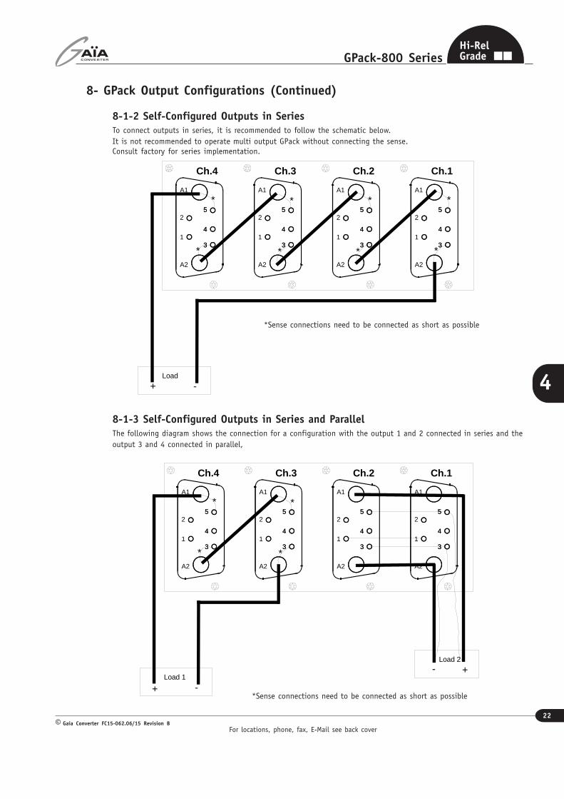
8- GPack Output Configurations (Continued)
8-1-2 Self-Configured Outputs in SeriesTo connect outputs in series, it is recommended to follow the schematic below.It is not recommended to operate multi output GPack without connecting the sense.Consult factory for series implementation.
3
4
5
A1
2
1
A2
3
4
5
3
4
5
A1
2
1
A2
3
4
5
3
4
5
A1
2
1
A2
3
4
5
3
4
5
A1
2
1
A2
3
4
5
Ch.4 Ch.3 Ch.2 Ch.1
+ -Load
*
* *
*
*
*
*
*
*Sense connections need to be connected as short as possible
8-1-3 Self-Configured Outputs in Series and ParallelThe following diagram shows the connection for a configuration with the output 1 and 2 connected in series and theoutput 3 and 4 connected in parallel,
3
4
5
A1
2
1
A2
3
4
5
3
4
5
A1
2
1
A2
3
4
5
3
4
5
A1
2
1
A2
3
4
5
3
4
5
A1
2
1
A2
3
4
5
Ch.4 Ch.3 Ch.2 Ch.1
+ -Load 1
*
* *
*
Load 2
+-
*Sense connections need to be connected as short as possible
For locations, phone, fax, E-Mail see back cover
23
GPack-800 Series
Gaia Converter FC15-062.06/15 Revision B©
4
Hi-RelGrade
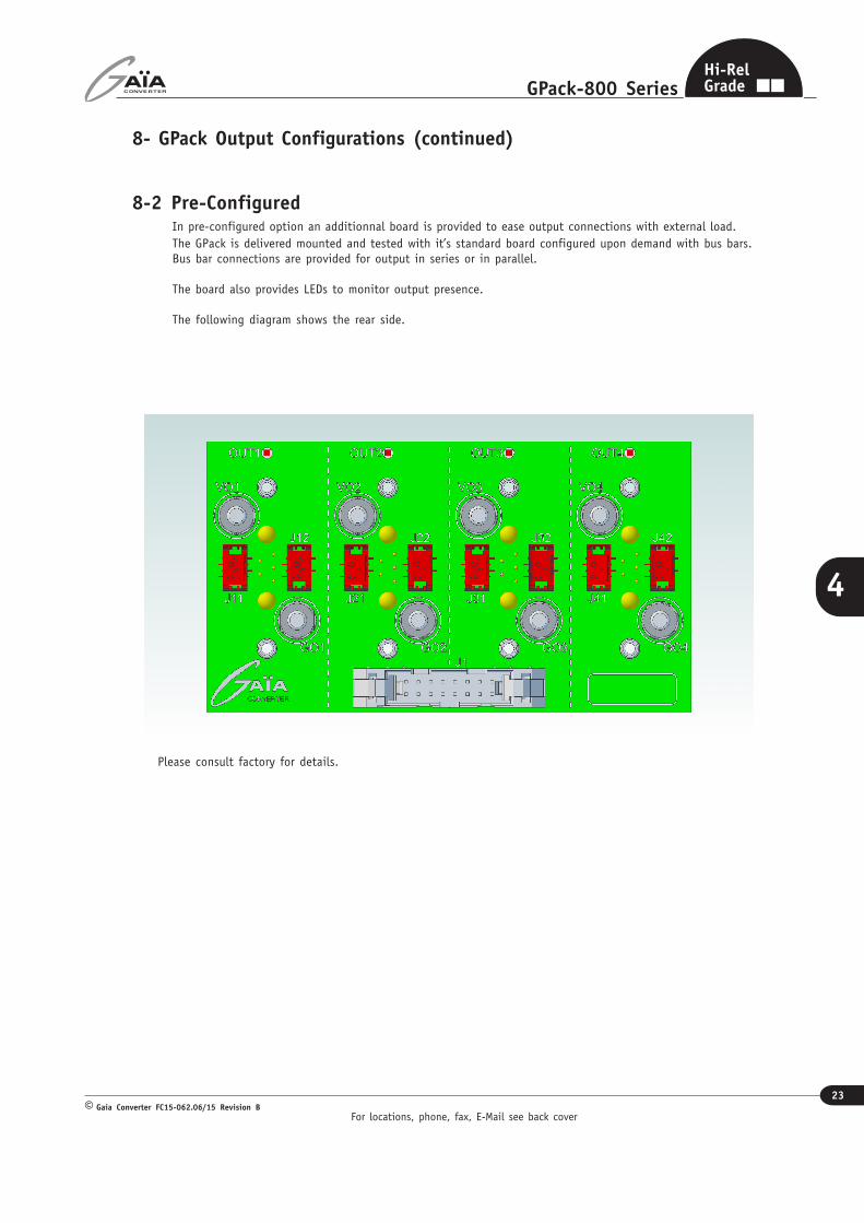
8- GPack Output Configurations (continued)
8-2 Pre-ConfiguredIn pre-configured option an additionnal board is provided to ease output connections with external load.The GPack is delivered mounted and tested with it’s standard board configured upon demand with bus bars.Bus bar connections are provided for output in series or in parallel.
The board also provides LEDs to monitor output presence.
The following diagram shows the rear side.
Please consult factory for details.
For locations, phone, fax, E-Mail see back cover
24
GPack-800 Series
Gaia Converter FC15-062.06/15 Revision B©
4
Hi-RelGrade
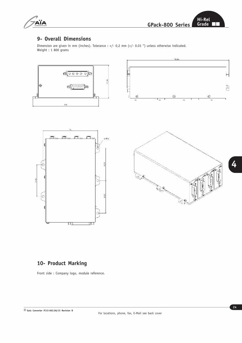
9- Overall Dimensions
10- Product Marking
Front side : Company logo, module reference.
Dimension are given in mm (inches). Tolerance : +/- 0,2 mm (+/- 0.01 “) unless otherwise indicated.Weight : 1 800 grams

Information given in this datasheet is believed to be accurate and reliable. However, no responsibility is assumed for the consequence of its use nor for any infringement of patents or other rights of third parties which may result from its use.These products are sold only according to GAIA Converter general conditions of sale, unless otherwise confirmed by writing. Specifications subject to change without notice.
Pri
nte
d i
n F
rance
by
GA
IA C
onve
rter
Gai
a Co
nve
rter
FC1
5-0
62.0
5/0
9 R
evis
ion B
. G
raphis
me
: Phil
ippe
Clic
q
Represented by :
For more detailed specifications and applications information, contact :
International HeadquartersGAÏA Converter - France
ZI de la Morandière33185 LE HAILLAN - FRANCETel. : + (33)-5-57-92-12-80Fax : + (33)-5-57-92-12-89
North American HeadquartersGAÏA Converter Canada, Inc4038 Le Corbusier BlvdLAVAL, QUEBEC - CANADA H7L 5R2Tel. : (514)-333-3169Fax : (514)-333-4519


![Untitled-1 [clubrunner.blob.core.windows.net]clubrunner.blob.core.windows.net/00000060079/en-ca/files/homepage/r… · Hats off to Rtn K T Shetty Dist Gov. Rtn Manjunath Shetty has](https://img.pdfslide.us/doc/110x75/606134c012d928261a544a5c/untitled-1-hats-off-to-rtn-k-t-shetty-dist-gov-rtn-manjunath-shetty-has-nominated.jpg)