Embed Size (px)
Citation preview
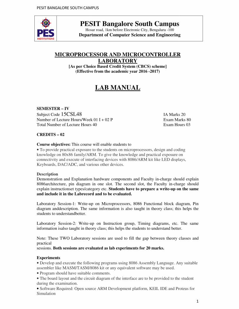
PESIT BANGALORE SOUTH CAMPUS
PESIT Bangalore South CampusHosur road, 1km before Electronic City, Bengaluru
Department of
MICROPROCESSOR AND MICROCONTROLLER
[As per Choice Based Credit System (CBCS) scheme]
(Effective from the academic year 2016
SEMESTER – IV
Subject Code 15CSL48 Number of Lecture Hours/Week 01 I + 02 P Total Number of Lecture Hours 40
CREDITS – 02
Course objectives: This course will enable students to
• To provide practical exposure to the students on microprocessors, design and codingknowledge on 80x86 family/ARM. To give the knowledge and practical exposure onconnectivity and execute of interfacing devices with 8086/ARM kit like LED displays,Keyboards, DAC/ADC, and various other devices.
Description
Demonstration and Explanation hardware components and Faculty in8086architecture, pin diagram inexplain instructionset types/category etc. and include it in the Labrecord and to be evaluated. Laboratory Session-1: Write-up on Microprocessors, 808diagram anddescription. The same information is also taught in theory class; this helps the students to understandbetter. Laboratory Session-2: Write-information isalso taught in theory class; this helps the students to understand better. Note: These TWO Laboratory sessions are used to fill the gap between theory classes and practical sessions. Both sessions are evaluated as lab experiments for 20 marks.
Experiments
• Develop and execute the following programs using 8086 Assembly Language. Any suitableassembler like MASM/TASM/8086 kit or any equivalent software may be used.
• Program should have suitable comments.
• The board layout and the circuit diagram of the interduring the examination.
• Software Required: Open source ARM Development platform, KEIL IDE and Proteus forSimulation
PESIT BANGALORE SOUTH CAMPUS
PESIT Bangalore South CampusHosur road, 1km before Electronic City, Bengaluru -100
Department of Computer Science and Engineering
MICROPROCESSOR AND MICROCONTROLLER
LABORATORY Choice Based Credit System (CBCS) scheme]
(Effective from the academic year 2016 -2017)
LAB MANUAL
IA Marks 20
ure Hours/Week 01 I + 02 P Exam Marks 80umber of Lecture Hours 40 Exam Hours 03
This course will enable students to
To provide practical exposure to the students on microprocessors, design and codingknowledge on 80x86 family/ARM. To give the knowledge and practical exposure on
ivity and execute of interfacing devices with 8086/ARM kit like LED displays,Keyboards, DAC/ADC, and various other devices.
Demonstration and Explanation hardware components and Faculty in-charge should explain 8086architecture, pin diagram in one slot. The second slot, the Faculty in-charge should explain instructionset types/category etc. Students have to prepare a write-up on the same
and include it in the Labrecord and to be evaluated.
up on Microprocessors, 8086 Functional block diagram, Pin diagram anddescription. The same information is also taught in theory class; this helps the
-up on Instruction group, Timing diagrams, etc. The same o taught in theory class; this helps the students to understand better.
Note: These TWO Laboratory sessions are used to fill the gap between theory classes and
Both sessions are evaluated as lab experiments for 20 marks.
Develop and execute the following programs using 8086 Assembly Language. Any suitableassembler like MASM/TASM/8086 kit or any equivalent software may be used.
Program should have suitable comments.
The board layout and the circuit diagram of the interface are to be provided to the student
Software Required: Open source ARM Development platform, KEIL IDE and Proteus for
1
PESIT Bangalore South Campus
Computer Science and Engineering
MICROPROCESSOR AND MICROCONTROLLER
IA Marks 20
Exam Marks 80 Exam Hours 03
To provide practical exposure to the students on microprocessors, design and coding knowledge on 80x86 family/ARM. To give the knowledge and practical exposure on
ivity and execute of interfacing devices with 8086/ARM kit like LED displays,
charge should explain charge should
up on the same
6 Functional block diagram, Pin diagram anddescription. The same information is also taught in theory class; this helps the
up on Instruction group, Timing diagrams, etc. The same o taught in theory class; this helps the students to understand better.
Note: These TWO Laboratory sessions are used to fill the gap between theory classes and
Develop and execute the following programs using 8086 Assembly Language. Any suitable
face are to be provided to the student
Software Required: Open source ARM Development platform, KEIL IDE and Proteus for
PESIT BANGALORE SOUTH CAMPUS
2
SOFTWARE PROGRAMS: PART A
1. Design and develop an assembly language program to search a key element “X” in a list of ‘n’16-bit numbers. Adopt Binary search algorithm in your program for searching. 2. Design and develop an assembly program to sort a given set of ‘n’ 16-bit numbers in ascending order. Adopt Bubble Sort algorithm to sort given elements. 3. Develop an assembly language program to reverse a given string and verify whether it is a palindrome or not. Display the appropriate message. 4. Develop an assembly language program to compute nCr using recursive procedure. Assumethat ‘n’ and ‘r’ are non-negative integers. 5. Design and develop an assembly language program to read the current time and Date from thesystem and display it in the standard format on the screen. 6. To write and simulate ARM assembly language programs for data transfer, arithmetic and logical operations (Demonstrate with the help of a suitable program). 7. To write and simulate C Programs for ARM microprocessor using KEIL (Demonstrate withthe help of a suitable program) Note : To use KEIL one may refer the book: Insider’s Guide to the ARM7 based
microcontrollers, Hitex Ltd.,1st edition, 2005
HARDWARE PROGRAMS: PART B
8. a. Design and develop an assembly program to demonstrate BCD Up-Down Counter (00-99)on the Logic Controller Interface. b. Design and develop an assembly program to read the status of two 8-bit inputs (X & Y) from the Logic Controller Interface and display X*Y. 9. Design and develop an assembly program to display messages “FIRE” and “HELP” alternately with flickering effects on a 7-segment display interface for a suitable period of time. Ensure a flashing rate that makes it easy to read both the messages (Examiner does not specify these delay values nor is it necessary for the student to compute these values). 10. Design and develop an assembly program to drive a Stepper Motor interface and rotate themotor in specified direction (clockwise or counter-clockwise) by N steps (Direction and N are specified by the examiner). Introduce suitable delay between successive steps. (Any arbitrary value for the delay may be assumed by the student). 11. Design and develop an assembly language program to a. Generate the Sine Wave using DAC interface (The output of the DAC is to be displayed on the CRO). b. Generate a Half Rectified Sine waveform using the DAC interface. (The output of the DAC is to be displayed on the CRO). 12. To interface LCD with ARM processor-- ARM7TDMI/LPC2148. Write and execute programs in C language for displaying text messages and numbers on LCD
PESIT BANGALORE SOUTH CAMPUS
3
13. To interface Stepper motor with ARM processor-- ARM7TDMI/LPC2148. Write a programto rotate stepper motor
Study Experiments: 1. Interfacing of temperature sensor with ARM freedom board (or any other ARM microprocessor board) and display temperature on LCD 2. To design ARM cortex based automatic number plate recognition system 3. To design ARM based power saving system Course Outcomes: After studying this course, students will be able to
• Learn 80x86 instruction sets and gins the knowledge of how assembly language works.
• Design and implement programs written in 80x86 assembly language
• Know functioning of hardware devices and interfacing them to x86 family
• Choose processors for various kinds of applications. Graduate Attributes
• Engineering Knowledge
• Problem Analysis
• Modern Tool Usage
• Conduct Investigations of Complex Problems
• Design/Development of Solutions
Conduction of Practical Examination:
• All laboratory experiments (all 7 + 6 nos) are to be included for practical examination.
• Students are allowed to pick one experiment from each of the lot.
• Strictly follow the instructions as printed on the cover page of answer script for breakup of marks
• PART –A: Procedure + Conduction + Viva: 10 + 25 +05 (40)
• PART –B: Procedure + Conduction + Viva: 10 + 25 +05 (40)
• Change of experiment is allowed only once and marks allotted to the procedure part to be made zero.
PESIT BANGALORE SOUTH CAMPUS
4
CONTENTS
SOFTWARE PROGRAMS
1. BINARY SEARCH
2. BUBBLE SORT
3. PALINDROME.
4. NCR
5. SET TIME AND DATE
6. ARM ASSEMBLY LANGUAGE PROGRAMS
7. ARM PROGRAMMING USING C.
HARDWARE PROGRAMS
1. BCD UP COUNTER
2. DISPLAY X * Y
3. DISPLAY FIRE AND HELP
4. STEPPER MOTOR INTERFACE TO MICROPROCESSOR
5. USING DAC GENERATE I) SINE WAVE
II) HALF RECTIFIED WAVE.
6. INTERFACING LCD TO ARM PROCESSOR
7. INTERFACING STEPPER MOTOR TO ARM PROCESSOR
PESIT BANGALORE SOUTH CAMPUS
5
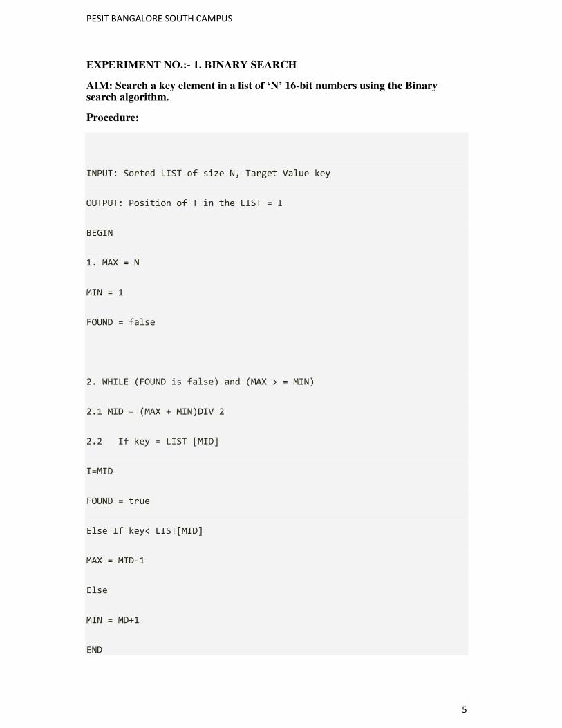
EXPERIMENT NO.:- 1. BINARY SEARCH
AIM: Search a key element in a list of ‘N’ 16-bit numbers using the Binary search algorithm.
Procedure:
INPUT: Sorted LIST of size N, Target Value key
OUTPUT: Position of T in the LIST = I
BEGIN
1. MAX = N
MIN = 1
FOUND = false
2. WHILE (FOUND is false) and (MAX > = MIN)
2.1 MID = (MAX + MIN)DIV 2
2.2 If key = LIST [MID]
I=MID
FOUND = true
Else If key< LIST[MID]
MAX = MID-1
Else
MIN = MD+1
END
PESIT BANGALORE SOUTH CAMPUS
6
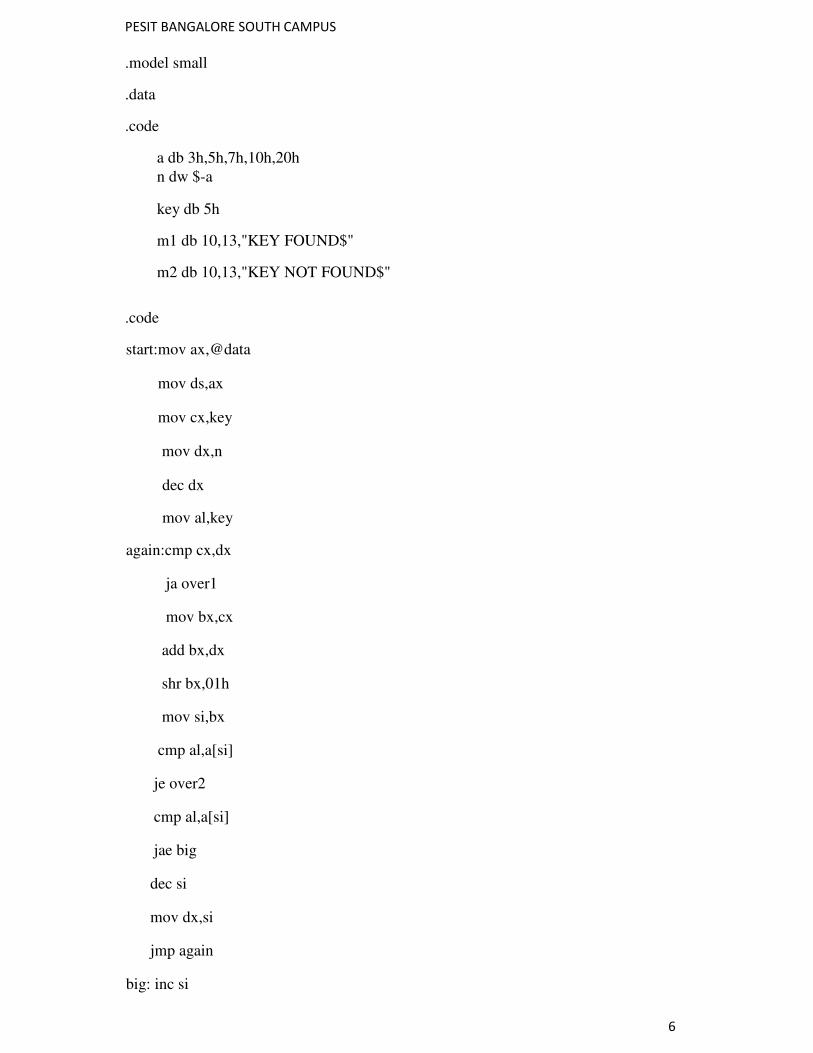
.model small
.data
.code
a db 3h,5h,7h,10h,20h
n dw $-a
key db 5h
m1 db 10,13,"KEY FOUND$"
m2 db 10,13,"KEY NOT FOUND$"
.code
start:mov ax,@data
mov ds,ax
mov cx,key
mov dx,n
dec dx
mov al,key
again:cmp cx,dx
ja over1
mov bx,cx
add bx,dx
shr bx,01h
mov si,bx
cmp al,a[si]
je over2
cmp al,a[si]
jae big
dec si
mov dx,si
jmp again
big: inc si
PESIT BANGALORE SOUTH CAMPUS
7
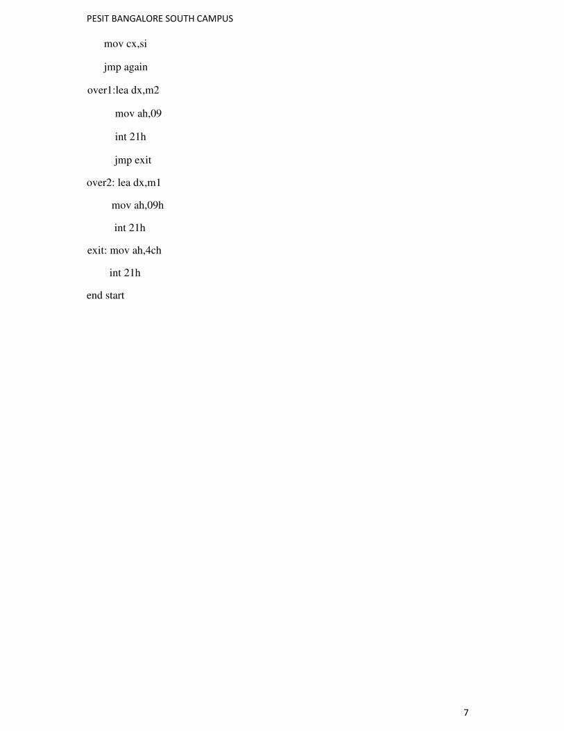
mov cx,si
jmp again
over1:lea dx,m2
mov ah,09
int 21h
jmp exit
over2: lea dx,m1
mov ah,09h
int 21h
exit: mov ah,4ch
int 21h
end start
PESIT BANGALORE SOUTH CAMPUS
8
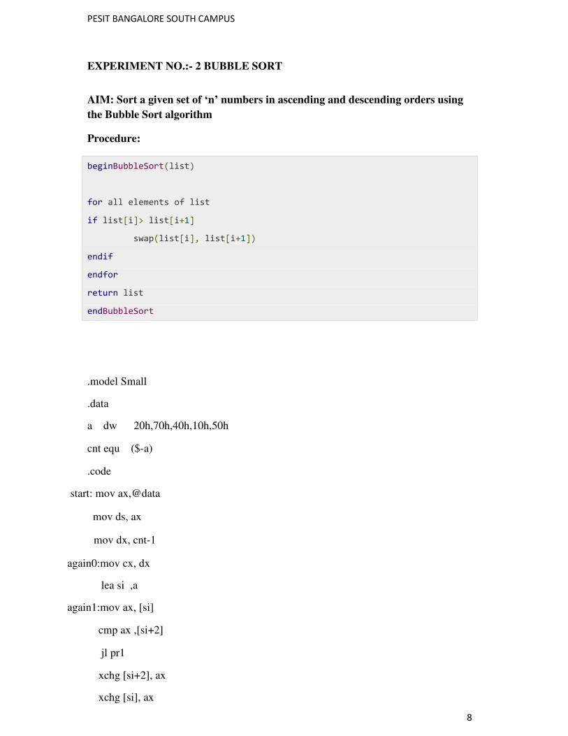
EXPERIMENT NO.:- 2 BUBBLE SORT
AIM: Sort a given set of ‘n’ numbers in ascending and descending orders using
the Bubble Sort algorithm
Procedure:
beginBubbleSort(list)
for all elements of list
if list[i]> list[i+1]
swap(list[i], list[i+1])
endif
endfor
return list
endBubbleSort
.model Small
.data
a dw 20h,70h,40h,10h,50h
cnt equ ($-a)
.code
start: mov ax,@data
mov ds, ax
mov dx, cnt-1
again0:mov cx, dx
lea si ,a
again1:mov ax, [si]
cmp ax ,[si+2]
jl pr1
xchg [si+2], ax
xchg [si], ax

PESIT BANGALORE SOUTH CAMPUS
9
pr1: add si,02
loop again1
dec dx
jnz again0
mov ah,4ch
int 21h
end start
PESIT BANGALORE SOUTH CAMPUS
10
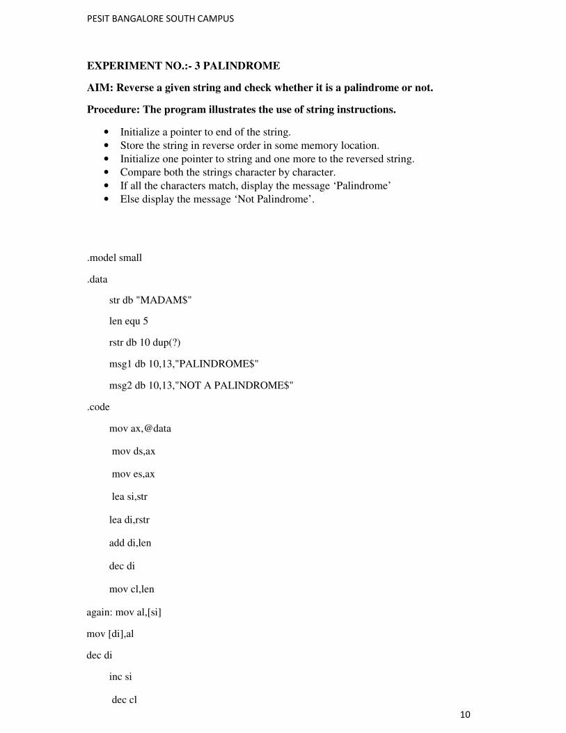
EXPERIMENT NO.:- 3 PALINDROME
AIM: Reverse a given string and check whether it is a palindrome or not.
Procedure: The program illustrates the use of string instructions.
• Initialize a pointer to end of the string.
• Store the string in reverse order in some memory location.
• Initialize one pointer to string and one more to the reversed string.
• Compare both the strings character by character.
• If all the characters match, display the message ‘Palindrome’
• Else display the message ‘Not Palindrome’.
.model small
.data
str db "MADAM$"
len equ 5
rstr db 10 dup(?)
msg1 db 10,13,"PALINDROME$"
msg2 db 10,13,"NOT A PALINDROME$"
.code
mov ax,@data
mov ds,ax
mov es,ax
lea si,str
lea di,rstr
add di,len
dec di
mov cl,len
again: mov al,[si]
mov [di],al
dec di
inc si
dec cl
PESIT BANGALORE SOUTH CAMPUS
11
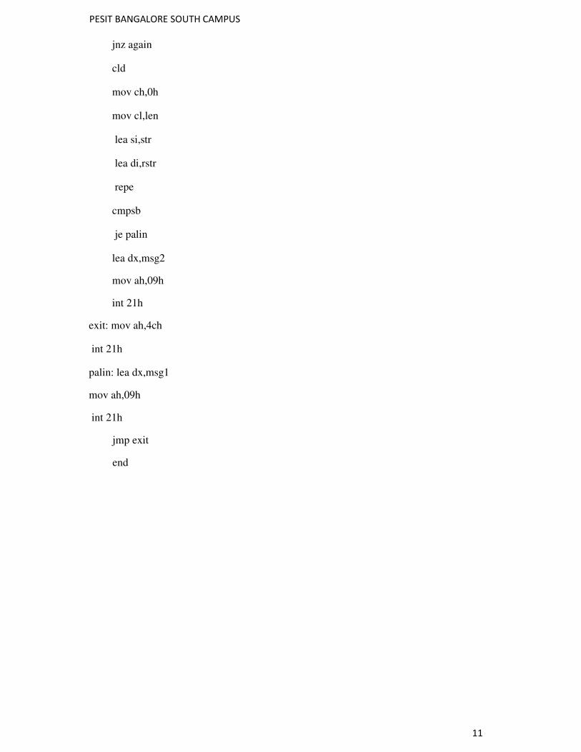
jnz again
cld
mov ch,0h
mov cl,len
lea si,str
lea di,rstr
repe
cmpsb
je palin
lea dx,msg2
mov ah,09h
int 21h
exit: mov ah,4ch
int 21h
palin: lea dx,msg1
mov ah,09h
int 21h
jmp exit
end
PESIT BANGALORE SOUTH CAMPUS
12
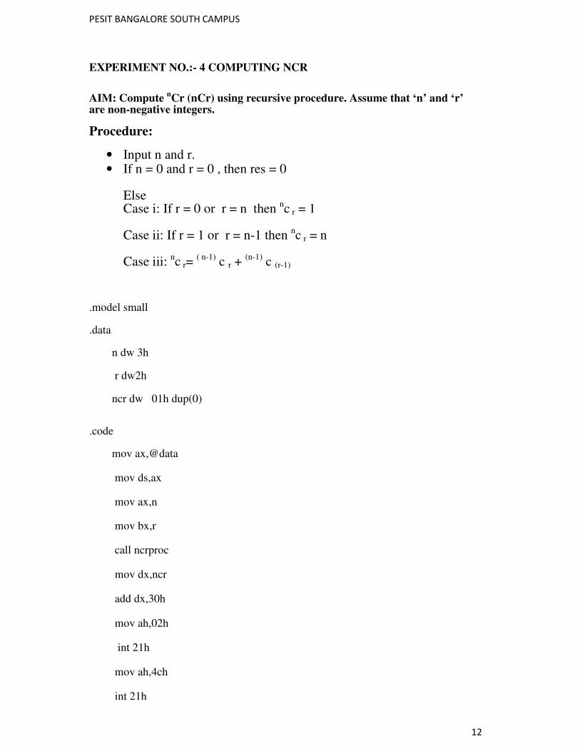
EXPERIMENT NO.:- 4 COMPUTING NCR
AIM: Compute nCr (nCr) using recursive procedure. Assume that ‘n’ and ‘r’
are non-negative integers.
Procedure:
• Input n and r. • If n = 0 and r = 0 , then res = 0
Else Case i: If r = 0 or r = n then nc r = 1 Case ii: If r = 1 or r = n-1 then nc r = n Case iii: nc r= ( n-1) c r + (n-1) c (r-1)
.model small
.data
n dw 3h
r dw2h
ncr dw 01h dup(0)
.code
mov ax,@data
mov ds,ax
mov ax,n
mov bx,r
call ncrproc
mov dx,ncr
add dx,30h
mov ah,02h
int 21h
mov ah,4ch
int 21h
PESIT BANGALORE SOUTH CAMPUS
13
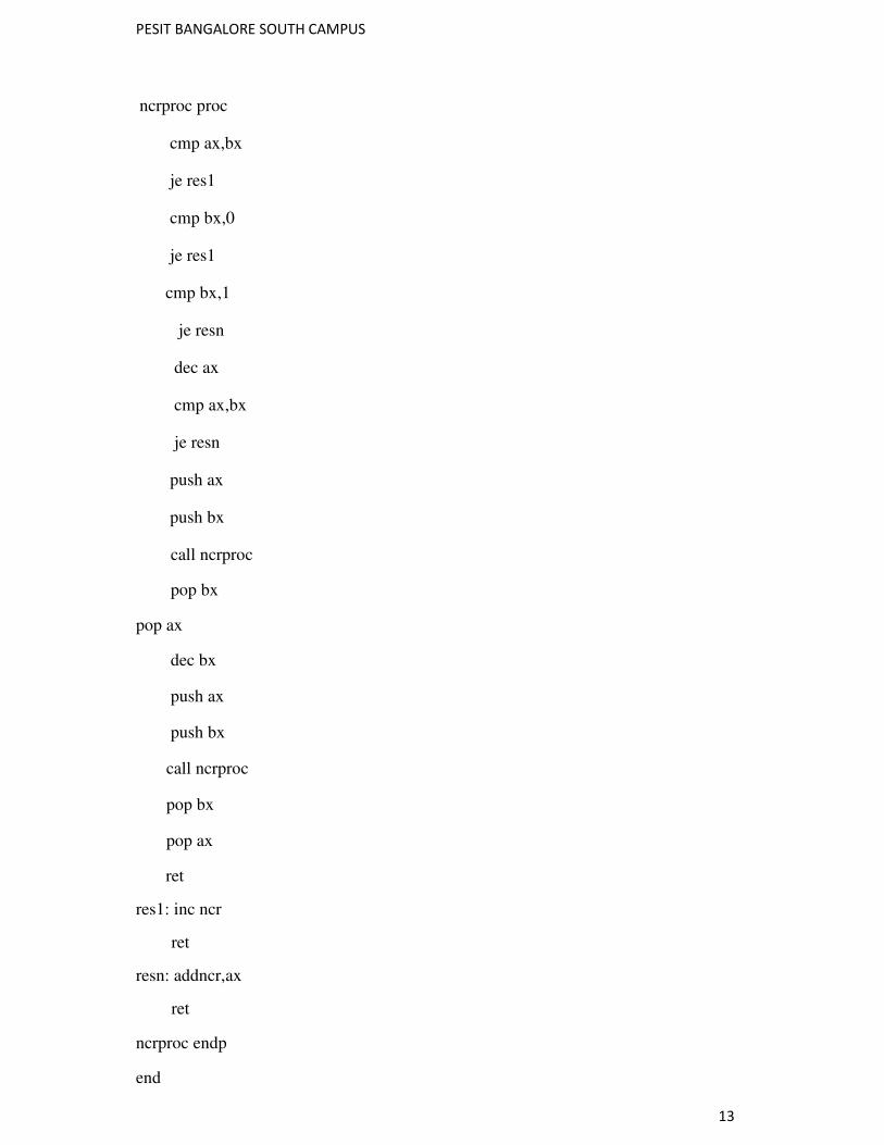
ncrproc proc
cmp ax,bx
je res1
cmp bx,0
je res1
cmp bx,1
je resn
dec ax
cmp ax,bx
je resn
push ax
push bx
call ncrproc
pop bx
pop ax
dec bx
push ax
push bx
call ncrproc
pop bx
pop ax
ret
res1: inc ncr
ret
resn: addncr,ax
ret
ncrproc endp
end
PESIT BANGALORE SOUTH CAMPUS
14
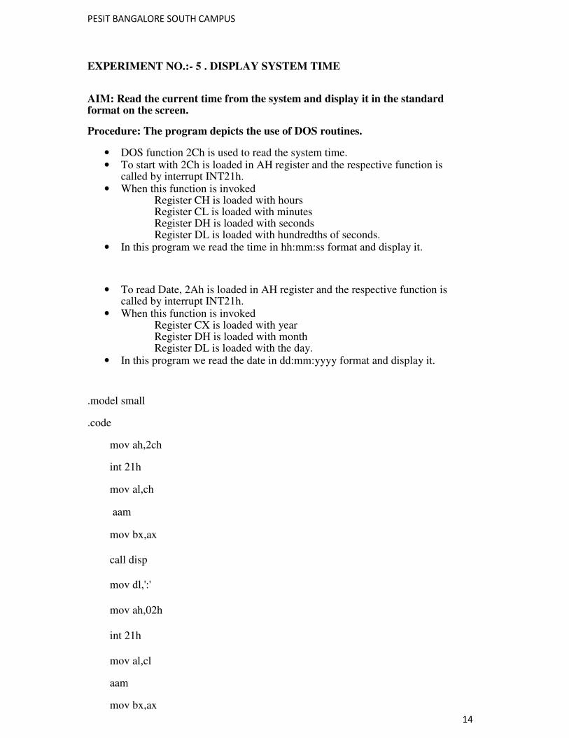
EXPERIMENT NO.:- 5 . DISPLAY SYSTEM TIME
AIM: Read the current time from the system and display it in the standard format on the screen.
Procedure: The program depicts the use of DOS routines.
• DOS function 2Ch is used to read the system time. • To start with 2Ch is loaded in AH register and the respective function is
called by interrupt INT21h. • When this function is invoked
Register CH is loaded with hours Register CL is loaded with minutes Register DH is loaded with seconds Register DL is loaded with hundredths of seconds.
• In this program we read the time in hh:mm:ss format and display it.
• To read Date, 2Ah is loaded in AH register and the respective function is called by interrupt INT21h.
• When this function is invoked Register CX is loaded with year Register DH is loaded with month Register DL is loaded with the day.
• In this program we read the date in dd:mm:yyyy format and display it.
.model small
.code
mov ah,2ch
int 21h
mov al,ch
aam
mov bx,ax
call disp
mov dl,':'
mov ah,02h
int 21h
mov al,cl
aam
mov bx,ax
PESIT BANGALORE SOUTH CAMPUS
15
call disp
mov al,dh
aam
mov bx,ax
call disp
mov dl,':'
mov ah,02h
int 21h
mov ah,4ch
int 21h
disp proc
mov dl,bh
add dl,30h
mov ah,02h
int 21h
mov dl,bl
add dl,30h
mov ah,02h
int 21h
ret
disp endp
end
PESIT BANGALORE SOUTH CAMPUS
16
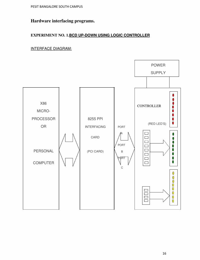
Hardware interfacing programs.
EXPERIMENT NO. 1.BCD UP-DOWN USING LOGIC CONTROLLER
INTERFACE DIAGRAM:
POWER
SUPPLY
CONTROLLER
(RED LED’S)
X86
MICRO-
PROCESSOR 8255 PPI
OR INTERFACING PORT
CARD
A
PORT
PERSONAL (PCI CARD) B
COMPUTER
PORT
C
PESIT BANGALORE SOUTH CAMPUS
17
.model small
.data
msg db 'press any key for returning to dos',13,10,'$' porta dw 9800h
portb dw 9801h
portc dw 9802h
ctlw dw 9803h
.code
mov ax,@data
mov ds,ax
mov dx,offset
msg mov ah,09h
int 21h
mov al,82h
mov dx,ctlw
out dx,al
mov dx,portb
in al,dx
cmp al,0ffh
je up4
up : mov al,00
up3 : push ax
mov ax,00h
mov ah,06h
mov dl,0ffh
int 21h
jnz quit
mov dx,porta
pop ax
out dx,al
call delayp
PESIT BANGALORE SOUTH CAMPUS
18
inc al
cmp al,0ah
je up
jmp up3
up4 : moval,09h
up5 : push ax
mov ax,00h
mov ah,06h
mov dl,0ffh
int 21h
jnz quit
mov dx,porta
pop ax
out dx,al
call delayp
dec al
cmp al,0ffh
je up4
jmp up5
quit : mov ah,4ch
int 21h
delay proc
push cx
push bx
mov cx,05fffh
up2 : mov bx,0ffffh
up1 : dec bx
jnz up1
loop up2
pop bx
PESIT BANGALORE SOUTH CAMPUS
19
pop cx
ret
delay endp
end
PESIT BANGALORE SOUTH CAMPUS
20
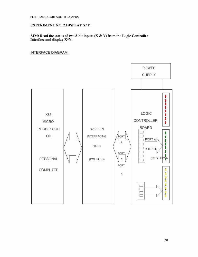
EXPERIMENT NO. 2.DISPLAY X*Y
AIM: Read the status of two 8-bit inputs (X & Y) from the Logic Controller Interface and display X*Y.
INTERFACE DIAGRAM:
POWER
SUPPLY
LOGIC
CONTROLLER
BOARD
PORT A
OUTPUT
(RED LED’S)
X86
MICRO-
PROCESSOR 8255 PPI
OR INTERFACING PORT
CARD
A
PORT
PERSONAL (PCI CARD) B
COMPUTER
PORT
C
PESIT BANGALORE SOUTH CAMPUS
21
.model small
.code
mov dx,9803h
mov al,82h
out dx,al
mov dx,9801h
in al,dx
movbl,al
in al,dx
mul bl
mov dx,9800h
out dx,al
mov al,ah
out dx,al
mov ah,4ch
int 21h
end
PESIT BANGALORE SOUTH CAMPUS
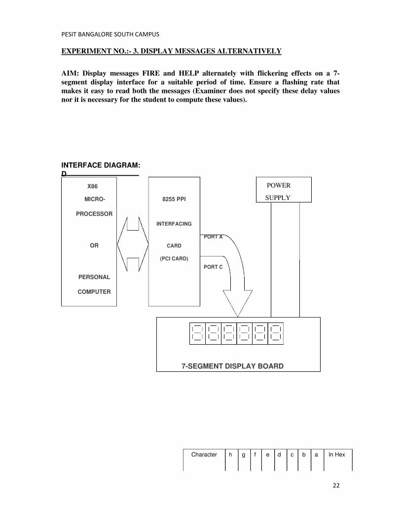
EXPERIMENT NO.:- 3. DISPLAY MESSAGES ALTERNATIVELY
AIM: Display messages FIRE and HELP
segment display interface for a suitable period of time. Ensure a flashing rate that
makes it easy to read both the messages (Examiner does not specify these delay values
nor it is necessary for the student to com
INTERFACE DIAGRAM:
D
X86
MICRO-
PROCESSOR
INTERFACING
OR
PERSONAL
COMPUTER
PESIT BANGALORE SOUTH CAMPUS
DISPLAY MESSAGES ALTERNATIVELY
AIM: Display messages FIRE and HELP alternately with flickering effects on a 7
segment display interface for a suitable period of time. Ensure a flashing rate that
makes it easy to read both the messages (Examiner does not specify these delay values
nor it is necessary for the student to compute these values).
POWER
SUPPLY
7-SEGMENT DISPLAY BOARD
8255 PPI
INTERFACING
PORT A
CARD
(PCI CARD)
PORT C
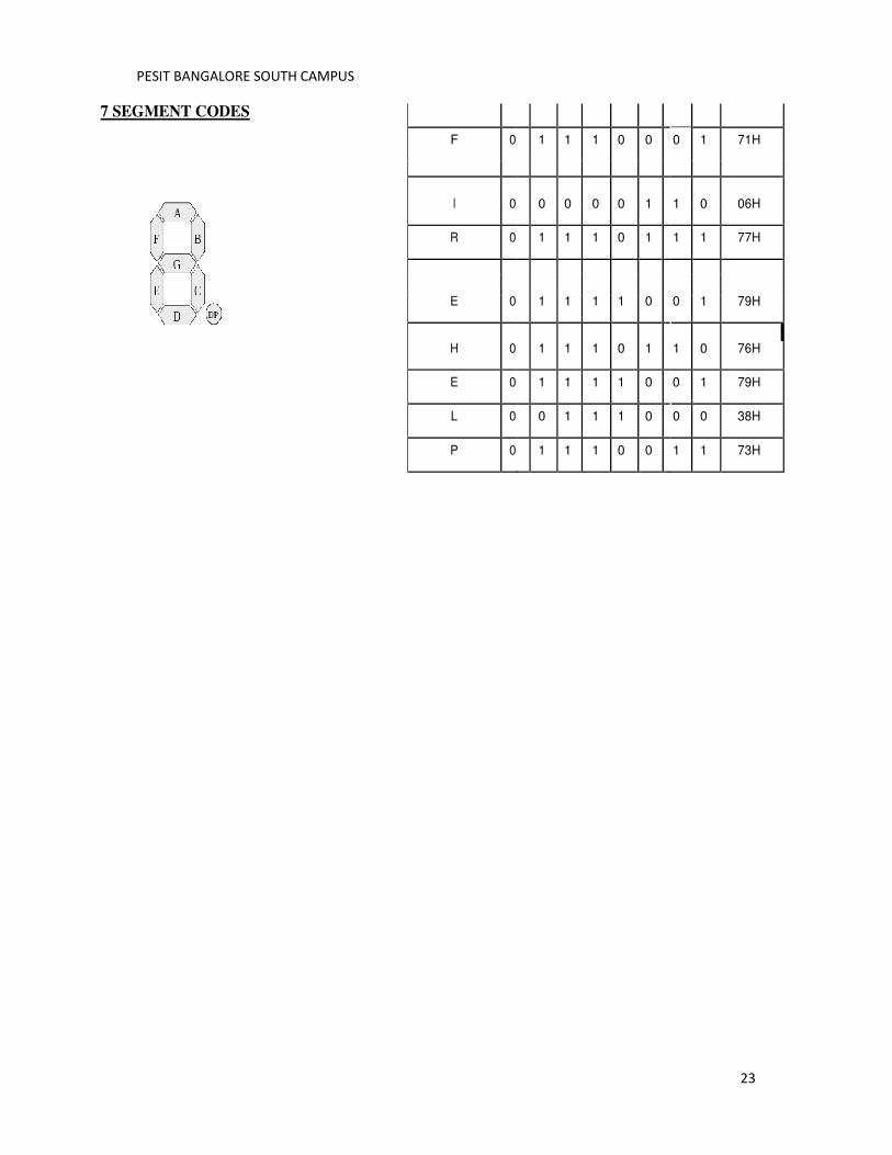
Character h g f e d c
22
alternately with flickering effects on a 7-
segment display interface for a suitable period of time. Ensure a flashing rate that
makes it easy to read both the messages (Examiner does not specify these delay values
b a In Hex
PESIT BANGALORE SOUTH CAMPUS
7 SEGMENT CODES
PESIT BANGALORE SOUTH CAMPUS
F 0 1 1 1 0 0
I 0
0 0 0 0 1
R 0 1 1 1 0 1
E 0
1 1 1 1 0
H 0 1 1 1 0 1
E 0 1 1 1 1 0
L 0 0 1 1 1 0
P 0 1 1 1 0 0
23
0 1 71H
1 0 06H
1 1 77H
0 1 79H
1 0 76H
0 1 79H
0 0 38H
1 1 73H
PESIT BANGALORE SOUTH CAMPUS
24
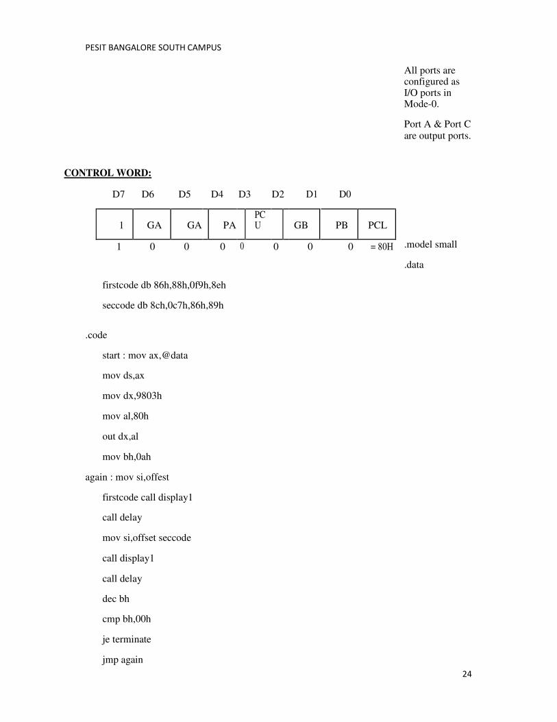
All ports are configured as I/O ports in Mode-0.
Port A & Port C are output ports.
.model small
.data
firstcode db 86h,88h,0f9h,8eh
seccode db 8ch,0c7h,86h,89h
.code
start : mov ax,@data
mov ds,ax
mov dx,9803h
mov al,80h
out dx,al
mov bh,0ah
again : mov si,offest
firstcode call display1
call delay
mov si,offset seccode
call display1
call delay
dec bh
cmp bh,00h
je terminate
jmp again
CONTROL WORD:
D7 D6 D5 D4 D3 D2 D1 D0
1 GA GA PA PCU GB PB PCL
1 0 0 0 0 0 0 0 = 80H
PESIT BANGALORE SOUTH CAMPUS
25
display1 proc
mov cx,04h
loop2 : mov
bl,08h mov al,[si]
next : ror al,01h
mov dx,9801h
out dx,al
push ax
mov al,0ffh
inc dx
out dx,al
mov al,00h
out dx,al
dec bl
pop ax
jz next1
jmp next
next1 : inc si
loop
loop2 ret
display1 endp
delay proc
push ax
push cx
mov cx,0ffffh
loop1 : mov ax,0fffh
loop3 : dec ax
jnz loop3
loop loop1
PESIT BANGALORE SOUTH CAMPUS
26
pop cx
pop ax
ret
delay endp
terminate : mov ah,4ch
int 21h
end start
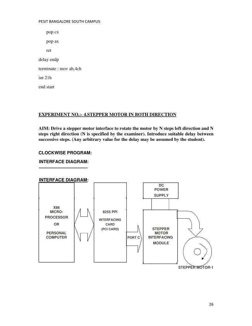
EXPERIMENT NO.:- 4.STEPPER MOTOR IN BOTH DIRECTION
AIM: Drive a stepper motor interface to rotate the motor by N steps left direction and N
steps right direction (N is specified by the examiner). Introduce suitable delay between
successive steps. (Any arbitrary value for the delay may be assumed by the student).
CLOCKWISE PROGRAM:
INTERFACE DIAGRAM:
INTERFACE DIAGRAM: DC POWER
SUPPLY
X86
MICRO- 8255 PPI
PROCESSOR INTERFACING
OR CARD
(PCI CARD) STEPPER PERSONAL MOTOR
COMPUTER PORT C INTERFACING
MODULE
STEPPER MOTOR-1
PESIT BANGALORE SOUTH CAMPUS
27
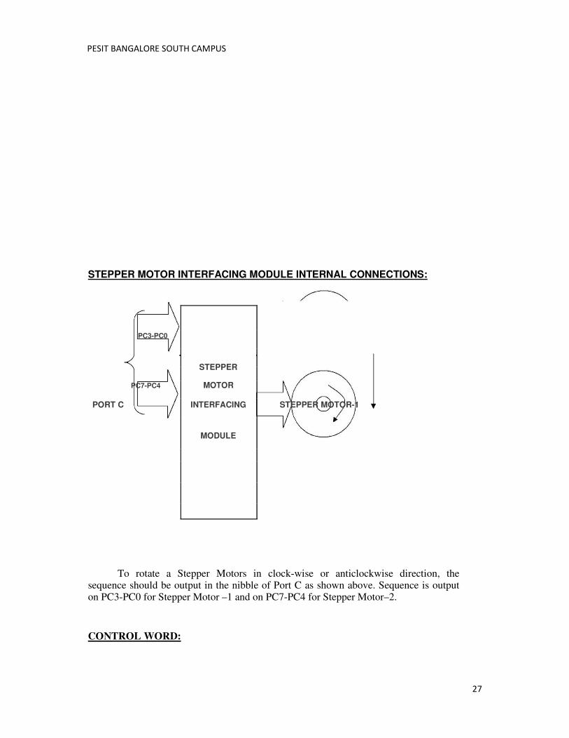
STEPPER MOTOR INTERFACING MODULE INTERNAL CONNECTIONS:
PC3-PC0
STEPPER
PC7-PC4 MOTOR
PORT C INTERFACING STEPPER MOTOR-1
MODULE
To rotate a Stepper Motors in clock-wise or anticlockwise direction, the sequence should be output in the nibble of Port C as shown above. Sequence is output on PC3-PC0 for Stepper Motor –1 and on PC7-PC4 for Stepper Motor–2.
CONTROL WORD:
PESIT BANGALORE SOUTH CAMPUS
28
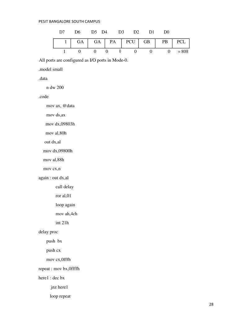
D7 D6 D5 D4 D3 D2 D1 D0
1 GA GA PA PCU GB PB PCL
1 0 0 0 0 0 0 0 = 80H
All ports are configured as I/O ports in Mode-0.
.model small
.data
n dw 200
.code
mov ax, @data
mov ds,ax
mov dx,09803h
mov al,80h
out dx,al
mov dx,09800h
mov al,88h
mov cx,n
again : out dx,al
call delay
ror al,01
loop again
mov ah,4ch
int 21h
delay proc
push bx
push cx
mov cx,0fffh
repeat : mov bx,0ffffh
here1 : dec bx
jnz here1
loop repeat
PESIT BANGALORE SOUTH CAMPUS
29
pop cx
pop bx
ret
delay
endp end
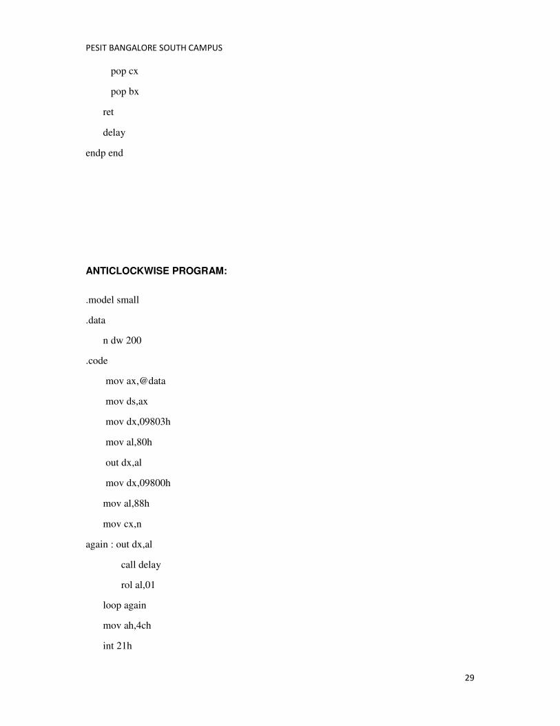
ANTICLOCKWISE PROGRAM:
.model small
.data
n dw 200
.code
mov ax,@data
mov ds,ax
mov dx,09803h
mov al,80h
out dx,al
mov dx,09800h
mov al,88h
mov cx,n
again : out dx,al
call delay
rol al,01
loop again
mov ah,4ch
int 21h
PESIT BANGALORE SOUTH CAMPUS
30
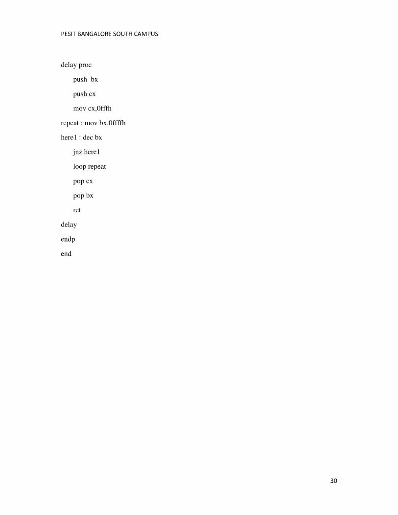
delay proc
push bx
push cx
mov cx,0fffh
repeat : mov bx,0ffffh
here1 : dec bx
jnz here1
loop repeat
pop cx
pop bx
ret
delay
endp
end
PESIT BANGALORE SOUTH CAMPUS
31
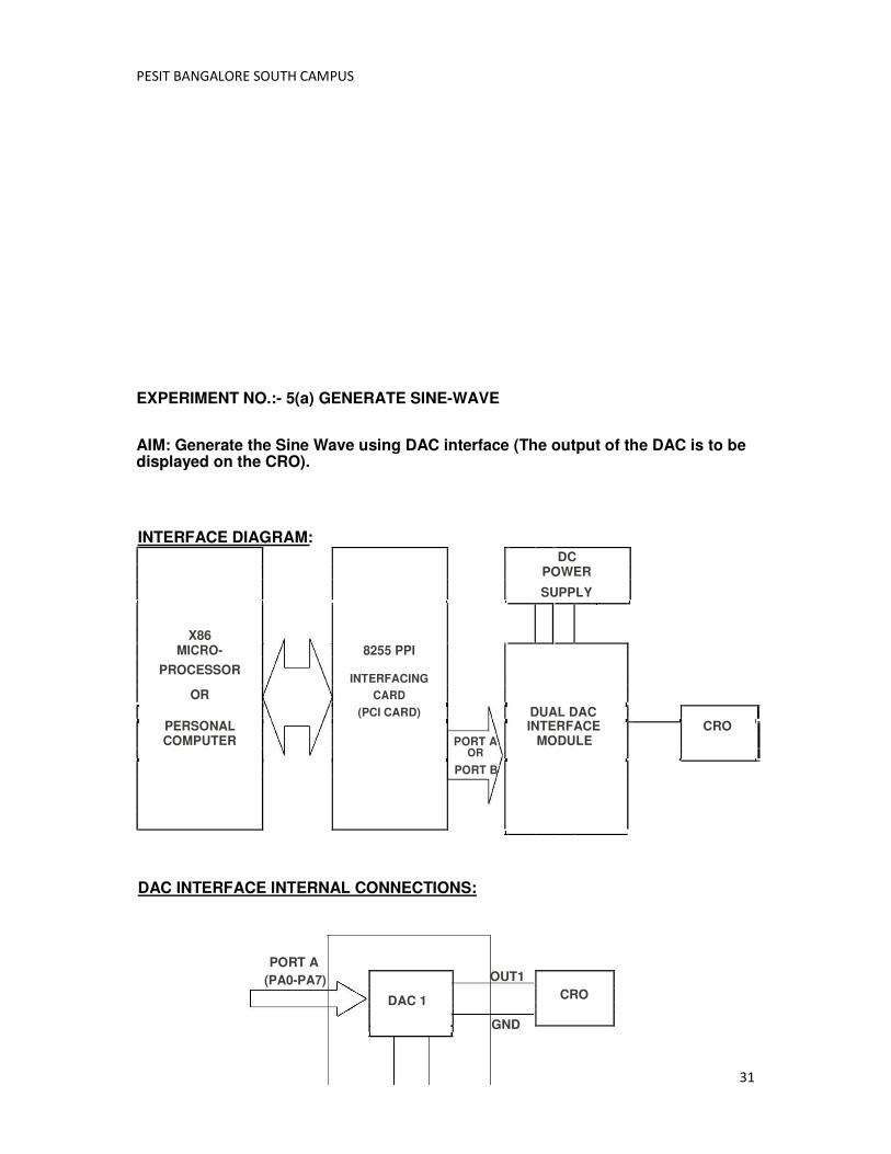
EXPERIMENT NO.:- 5(a) GENERATE SINE-WAVE
AIM: Generate the Sine Wave using DAC interface (The output of the DAC is to be displayed on the CRO).
INTERFACE DIAGRAM: DC POWER
SUPPLY
X86
MICRO- 8255 PPI
PROCESSOR INTERFACING
OR CARD
(PCI CARD) DUAL DAC
PERSONAL
INTERFACE
CRO
COMPUTER PORT A MODULE OR
PORT B
DAC INTERFACE INTERNAL CONNECTIONS:
PORT A
(PA0-PA7)
DAC 1
OUT1
CRO
GND
PESIT BANGALORE SOUTH CAMPUS
32
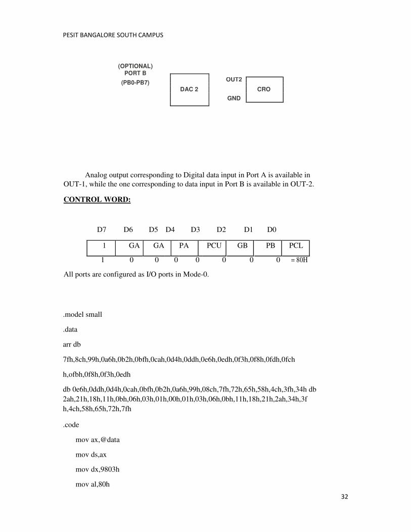
(OPTIONAL) PORT B
(PB0-PB7) OUT2
DAC 2 CRO
GND
Analog output corresponding to Digital data input in Port A is available in
OUT-1, while the one corresponding to data input in Port B is available in OUT-2.
CONTROL WORD:
D7 D6 D5 D4 D3 D2 D1 D0
1 GA GA PA PCU GB PB PCL
1 0 0 0 0 0 0 0 = 80H
All ports are configured as I/O ports in Mode-0.
.model small
.data
arr db
7fh,8ch,99h,0a6h,0b2h,0bfh,0cah,0d4h,0ddh,0e6h,0edh,0f3h,0f8h,0fdh,0fch
h,ofbh,0f8h,0f3h,0edh
db 0e6h,0ddh,0d4h,0cah,0bfh,0b2h,0a6h,99h,08ch,7fh,72h,65h,58h,4ch,3fh,34h db
2ah,21h,18h,11h,0bh,06h,03h,01h,00h,01h,03h,06h,0bh,11h,18h,21h,2ah,34h,3f
h,4ch,58h,65h,72h,7fh
.code
mov ax,@data
mov ds,ax
mov dx,9803h
mov al,80h
PESIT BANGALORE SOUTH CAMPUS
33
out dx,al
up1:lea si,arr
mov cx,60
up:mov al,[si]
mov dx,9800h
out dx,al
mov dx,9801h
out dx,al
call delay
inc si
loop up
jmp up1
mov ah,4ch
int 21h
delay proc
push bx
push cx
mov cx,0fh
repeat : mov bx,0ffh
here1 : dec bx
jnz here1
loop repeat
pop cx
pop bx
ret
delay endp end
EXPERIMENT NO.:- 5(b) HALF RECTIFIED SINE WAVE
PESIT BANGALORE SOUTH CAMPUS
34
AIM: Generate a Half Rectified Sine wave form using the DAC interface. (The output of the DAC is to be displayed on the CRO).
.model small
.data
arr db
7fh,8ch,99h,0a6h,0b2h,0bfh,0cah,0d4h,0ddh,0e6h,0edh,0f3h,0f8h,0fdh,0fc
h,ofbh,0f8h,0f3h,0edh
db 0e6h,0ddh,0d4h,0cah,0bfh,0b2h,0a6h,99h,08ch,7fh,72h,65h,58h,4ch,3fh,34h db
00h,00h,00h,00h,00h,00h,00h,00h,00h,00h,00h,00h,00h,00h,00h,00h,00h,00h,00h,
00h,00h,00h,00h,00h
.code
mov ax,@data
mov ds,ax
mov dx,9803h
mov al,80h
out dx,al
up1:lea si,arr
mov cx,60
up:mov al,[si]
mov dx,9800h
out dx,al
mov dx,9801h
out dx,al
call delay
inc si
loop up
jmp up1
mov ah,4ch
int 21h
delay proc
PESIT BANGALORE SOUTH CAMPUS
35
push bx
push cx
mov cx,0fh
repeat : mov bx,0ffh
here1 : dec bx
jnz here1
loop repeat
pop cx
pop bx
ret
delayendp
end