Embed Size (px)
DESCRIPTION
Manual for the MicroMite
Citation preview
Micromite MkII User Manual
MMBasic Ver 4.6b
For updates to this manual and more details on MMBasic go to http://geoffg.net/micromite.html
or http://mmbasic.com
Copyright 2011 - 2015 Geoff Graham This manual is licensed under a
Creative Commons Attribution-NonCommercial-ShareAlike 3.0 Australia (CC BY-NC-SA 3.0)
Micromite MkII User Manual Page 2
Contents Introduction............................................................................................................................. 3 Suitable Microcontrollers ........................................................................................................ 4
28-pin Micromite Connections ................................................................................................ 6 44-pin Micromite Connections ................................................................................................ 7
Quick Start Tutorial................................................................................................................. 8 Using MMBasic..................................................................................................................... 11
Micromite Special Features .................................................................................................. 13 Special Hardware Devices ................................................................................................... 16
Full Screen Editor ................................................................................................................. 24 Defining and Using Variables ............................................................................................... 26
Using the I/O pins................................................................................................................. 29 Timing................................................................................................................................... 32
Defined Subroutines and Functions...................................................................................... 33 Electrical Characteristics ...................................................................................................... 37
MMBasic Characteristics ...................................................................................................... 38 Predefined Read Only Variables .......................................................................................... 40 Commands ........................................................................................................................... 41
Functions.............................................................................................................................. 60 Obsolete Commands and Functions .................................................................................... 66
Appendix A – Serial Communications .................................................................................. 67 Appendix B – I2C Communications...................................................................................... 71
Appendix C – 1-Wire Communications................................................................................. 77 Appendix D – SPI Communications...................................................................................... 78
Micromite MkII User Manual Page 3
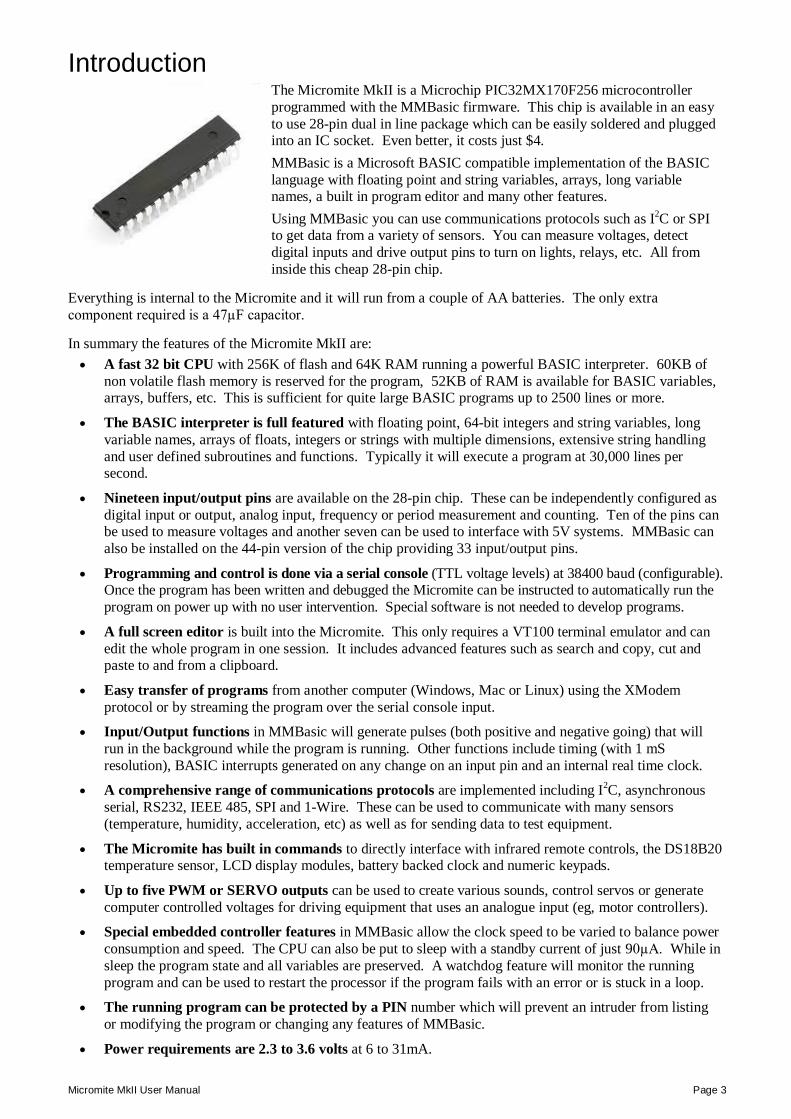
Introduction The Micromite MkII is a Microchip PIC32MX170F256 microcontroller programmed with the MMBasic firmware. This chip is available in an easy to use 28-pin dual in line package which can be easily soldered and plugged into an IC socket. Even better, it costs just $4. MMBasic is a Microsoft BASIC compatible implementation of the BASIC language with floating point and string variables, arrays, long variable names, a built in program editor and many other features. Using MMBasic you can use communications protocols such as I2C or SPI to get data from a variety of sensors. You can measure voltages, detect digital inputs and drive output pins to turn on lights, relays, etc. All from inside this cheap 28-pin chip.
Everything is internal to the Micromite and it will run from a couple of AA batteries. The only extra component required is a 47µF capacitor.
In summary the features of the Micromite MkII are: A fast 32 bit CPU with 256K of flash and 64K RAM running a powerful BASIC interpreter. 60KB of
non volatile flash memory is reserved for the program, 52KB of RAM is available for BASIC variables, arrays, buffers, etc. This is sufficient for quite large BASIC programs up to 2500 lines or more.
The BASIC interpreter is full featured with floating point, 64-bit integers and string variables, long variable names, arrays of floats, integers or strings with multiple dimensions, extensive string handling and user defined subroutines and functions. Typically it will execute a program at 30,000 lines per second.
Nineteen input/output pins are available on the 28-pin chip. These can be independently configured as digital input or output, analog input, frequency or period measurement and counting. Ten of the pins can be used to measure voltages and another seven can be used to interface with 5V systems. MMBasic can also be installed on the 44-pin version of the chip providing 33 input/output pins.
Programming and control is done via a serial console (TTL voltage levels) at 38400 baud (configurable). Once the program has been written and debugged the Micromite can be instructed to automatically run the program on power up with no user intervention. Special software is not needed to develop programs.
A full screen editor is built into the Micromite. This only requires a VT100 terminal emulator and can edit the whole program in one session. It includes advanced features such as search and copy, cut and paste to and from a clipboard.
Easy transfer of programs from another computer (Windows, Mac or Linux) using the XModem protocol or by streaming the program over the serial console input.
Input/Output functions in MMBasic will generate pulses (both positive and negative going) that will run in the background while the program is running. Other functions include timing (with 1 mS resolution), BASIC interrupts generated on any change on an input pin and an internal real time clock.
A comprehensive range of communications protocols are implemented including I2C, asynchronous serial, RS232, IEEE 485, SPI and 1-Wire. These can be used to communicate with many sensors (temperature, humidity, acceleration, etc) as well as for sending data to test equipment.
The Micromite has built in commands to directly interface with infrared remote controls, the DS18B20 temperature sensor, LCD display modules, battery backed clock and numeric keypads.
Up to five PWM or SERVO outputs can be used to create various sounds, control servos or generate computer controlled voltages for driving equipment that uses an analogue input (eg, motor controllers).
Special embedded controller features in MMBasic allow the clock speed to be varied to balance power consumption and speed. The CPU can also be put to sleep with a standby current of just 90µA. While in sleep the program state and all variables are preserved. A watchdog feature will monitor the running program and can be used to restart the processor if the program fails with an error or is stuck in a loop.
The running program can be protected by a PIN number which will prevent an intruder from listing or modifying the program or changing any features of MMBasic.
Power requirements are 2.3 to 3.6 volts at 6 to 31mA.
Micromite MkII User Manual Page 4
Suitable Microcontrollers The Micromite MkII firmware will run on all variants of the PIC32MX170F256 microcontroller, in both 28-pin and 44-pin packages. These are available from Microchip (http://www.microchipdirect.com) or their distributors – use Octopart (http://octopart.com) to search for suppliers.
28-pin Chips The best chip to use is the PIC32MX170F256B-50I/SP which is guaranteed to run up to 48MHz (the maximum Micromite speed) and is in a 28-pin DIL package. It costs about $4 direct from Microchip. There is a 40MHz variant (the PIC32MX170F256B-I/SP) which is a little cheaper. All of the 40MHz chips tested have run fine at 48MHz so this chip is also a good option.
The following is a summary of the recommended chips for the Micromite MkII in a 28-pin package:
PIC32MX170F256B-50I/SP Guaranteed to run at 48MHz. 28-pin DIL package.
PIC32MX170F256B-50I/SO As above but is in a surface mount SOIC package
PIC32MX170F256B-I/SP Should run at 48MHz despite its 40MHz spec. 28-pin DIL package.
PIC32MX170F256B-I/SO As above but is in a surface mount SOIC package
The firmware will also run on the PIC32MX270F256 series of chips. These have built in USB (which is not supported in the Micromite) and therefore you lose access to two I/O pins (pins 15 and 23) which are used in the chip for dedicated USB functions. In addition pins 21 and 22 are not 5V tolerant.
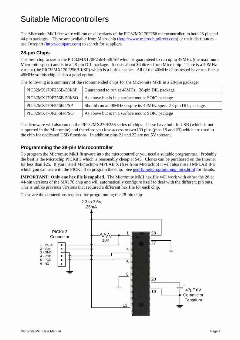
Programming the 28-pin Microcontroller To program the Micromite MkII firmware into the microcontroller you need a suitable programmer. Probably the best is the Microchip PICKit 3 which is reasonably cheap at $45. Clones can be purchased on the Internet for less than $25. If you install Microchip's MPLAB X (free from Microchip) it will also install MPLAB IPE which you can use with the PICKit 3 to program the chip. See geoffg.net/programming_pics.html for details.
IMPORTANT: Only one hex file is supplied. The Micromite MkII hex file will work with either the 28 or 44-pin versions of the MX170 chip and will automatically configure itself to deal with the different pin outs. This is unlike previous versions that required a different hex file for each chip.
These are the connections required for programming the 28-pin chip:
10K
+47µF 6V
Ceramic or Tantalum
2.3 to 3.6V 26mA
1
13
19
20
27
28
1 - MCLR2 - Vcc3 - GND4 - PGD5 - PGC6 - NC
PICKit 3Connector
4
5
8
Micromite MkII User Manual Page 5
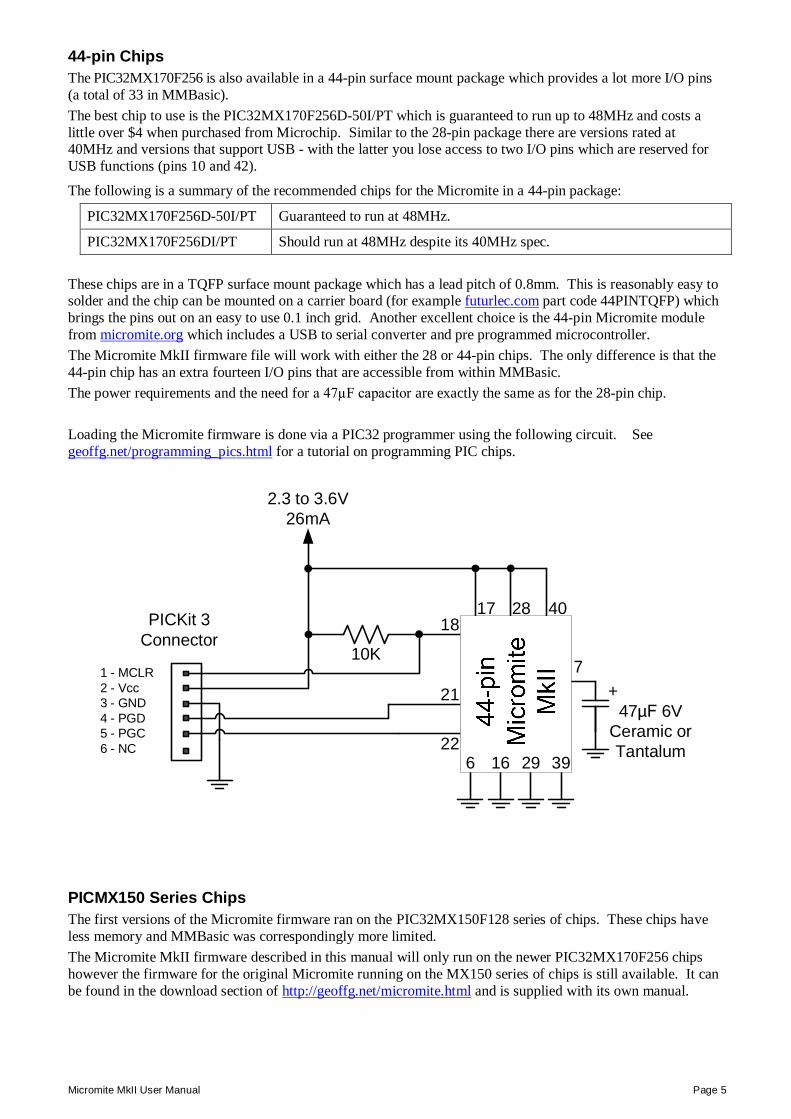
44-pin Chips The PIC32MX170F256 is also available in a 44-pin surface mount package which provides a lot more I/O pins (a total of 33 in MMBasic). The best chip to use is the PIC32MX170F256D-50I/PT which is guaranteed to run up to 48MHz and costs a little over $4 when purchased from Microchip. Similar to the 28-pin package there are versions rated at 40MHz and versions that support USB - with the latter you lose access to two I/O pins which are reserved for USB functions (pins 10 and 42).
The following is a summary of the recommended chips for the Micromite in a 44-pin package:
PIC32MX170F256D-50I/PT Guaranteed to run at 48MHz.
PIC32MX170F256DI/PT Should run at 48MHz despite its 40MHz spec. These chips are in a TQFP surface mount package which has a lead pitch of 0.8mm. This is reasonably easy to solder and the chip can be mounted on a carrier board (for example futurlec.com part code 44PINTQFP) which brings the pins out on an easy to use 0.1 inch grid. Another excellent choice is the 44-pin Micromite module from micromite.org which includes a USB to serial converter and pre programmed microcontroller. The Micromite MkII firmware file will work with either the 28 or 44-pin chips. The only difference is that the 44-pin chip has an extra fourteen I/O pins that are accessible from within MMBasic. The power requirements and the need for a 47µF capacitor are exactly the same as for the 28-pin chip. Loading the Micromite firmware is done via a PIC32 programmer using the following circuit. See geoffg.net/programming_pics.html for a tutorial on programming PIC chips.
10K
+47µF 6V
Ceramic or Tantalum
2.3 to 3.6V 26mA
18
71 - MCLR2 - Vcc3 - GND4 - PGD5 - PGC6 - NC
PICKit 3Connector
21
22
17 4028
6 16 29 39
PICMX150 Series Chips The first versions of the Micromite firmware ran on the PIC32MX150F128 series of chips. These chips have less memory and MMBasic was correspondingly more limited. The Micromite MkII firmware described in this manual will only run on the newer PIC32MX170F256 chips however the firmware for the original Micromite running on the MX150 series of chips is still available. It can be found in the download section of http://geoffg.net/micromite.html and is supplied with its own manual.
Micromite MkII User Manual Page 6
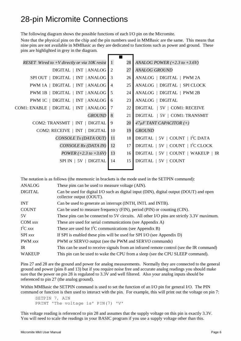
28-pin Micromite Connections The following diagram shows the possible functions of each I/O pin on the Micromite. Note that the physical pins on the chip and the pin numbers used in MMBasic are the same. This means that nine pins are not available in MMBasic as they are dedicated to functions such as power and ground. These pins are highlighted in grey in the diagram.
RESET Wired to +V directly or via 10K resist 1 28 ANALOG POWER (+2.3 to +3.6V)
DIGITAL | INT | ANALOG 2 27 ANALOG GROUND
SPI OUT | DIGITAL | INT | ANALOG 3 26 ANALOG | DIGITAL | PWM 2A
PWM 1A | DIGITAL | INT | ANALOG 4 25 ANALOG | DIGITAL | SPI CLOCK
PWM 1B | DIGITAL | INT | ANALOG 5 24 ANALOG | DIGITAL | PWM 2B
PWM 1C | DIGITAL | INT | ANALOG 6 23 ANALOG | DIGITAL
COM1: ENABLE | DIGITAL | INT | ANALOG 7 22 DIGITAL | 5V | COM1: RECEIVE
GROUND 8 21 DIGITAL | 5V | COM1: TRANSMIT
COM2: TRANSMIT | INT | DIGITAL 9 20 47µF TANT CAPACITOR (+)
COM2: RECEIVE | INT | DIGITAL 10 19 GROUND
CONSOLE Tx (DATA OUT) 11 18 DIGITAL | 5V | COUNT | I2C DATA
CONSOLE Rx (DATA IN) 12 17 DIGITAL | 5V | COUNT | I2C CLOCK
POWER (+2.3 to +3.6V) 13 16 DIGITAL | 5V | COUNT | WAKEUP | IR
SPI IN | 5V | DIGITAL 14 15 DIGITAL | 5V | COUNT
The notation is as follows (the mnemonic in brackets is the mode used in the SETPIN command): ANALOG These pins can be used to measure voltage (AIN). DIGITAL Can be used for digital I/O such as digital input (DIN), digital output (DOUT) and open
collector output (OOUT). INT Can be used to generate an interrupt (INTH, INTL and INTB). COUNT Can be used to measure frequency (FIN), period (PIN) or counting (CIN). 5V These pins can be connected to 5V circuits. All other I/O pins are strictly 3.3V maximum. COM xxx These are used for serial communications (see Appendix A) I2C xxx These are used for I2C communications (see Appendix B) SPI xxx If SPI is enabled these pins will be used for SPI I/O (see Appendix D) PWM xxx PWM or SERVO output (see the PWM and SERVO commands) IR This can be used to receive signals from an infrared remote control (see the IR command) WAKEUP This pin can be used to wake the CPU from a sleep (see the CPU SLEEP command).
Pins 27 and 28 are the ground and power for analog measurements. Normally they are connected to the general ground and power (pins 8 and 13) but if you require noise free and accurate analog readings you should make sure that the power on pin 28 is regulated to 3.3V and well filtered. Also your analog inputs should be referenced to pin 27 (the analog ground).
Within MMBasic the SETPIN command is used to set the function of an I/O pin for general I/O. The PIN command or function is then used to interact with the pin. For example, this will print out the voltage on pin 7:
SETPIN 7, AIN PRINT "The voltage is" PIN(7) "V"
This voltage reading is referenced to pin 28 and assumes that the supply voltage on this pin is exactly 3.3V. You will need to scale the readings in your BASIC program if you use a supply voltage other than this.
Micromite MkII User Manual Page 7
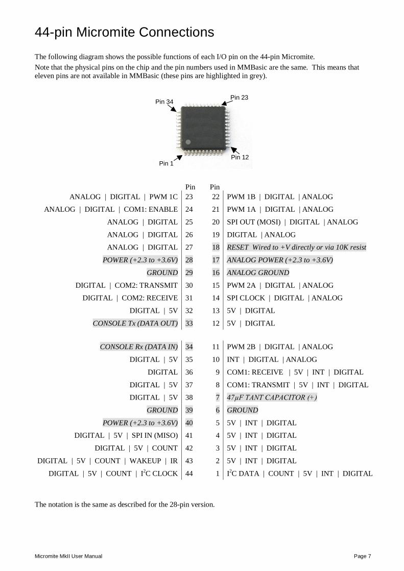
44-pin Micromite Connections The following diagram shows the possible functions of each I/O pin on the 44-pin Micromite. Note that the physical pins on the chip and the pin numbers used in MMBasic are the same. This means that eleven pins are not available in MMBasic (these pins are highlighted in grey).
Pin 1Pin 12
Pin 23Pin 34
Pin Pin ANALOG | DIGITAL | PWM 1C 23 22 PWM 1B | DIGITAL | ANALOG
ANALOG | DIGITAL | COM1: ENABLE 24 21 PWM 1A | DIGITAL | ANALOG
ANALOG | DIGITAL 25 20 SPI OUT (MOSI) | DIGITAL | ANALOG
ANALOG | DIGITAL 26 19 DIGITAL | ANALOG
ANALOG | DIGITAL 27 18 RESET Wired to +V directly or via 10K resist
POWER (+2.3 to +3.6V) 28 17 ANALOG POWER (+2.3 to +3.6V)
GROUND 29 16 ANALOG GROUND
DIGITAL | COM2: TRANSMIT 30 15 PWM 2A | DIGITAL | ANALOG
DIGITAL | COM2: RECEIVE 31 14 SPI CLOCK | DIGITAL | ANALOG
DIGITAL | 5V 32 13 5V | DIGITAL
CONSOLE Tx (DATA OUT) 33 12 5V | DIGITAL
CONSOLE Rx (DATA IN) 34 11 PWM 2B | DIGITAL | ANALOG
DIGITAL | 5V 35 10 INT | DIGITAL | ANALOG
DIGITAL 36 9 COM1: RECEIVE | 5V | INT | DIGITAL
DIGITAL | 5V 37 8 COM1: TRANSMIT | 5V | INT | DIGITAL
DIGITAL | 5V 38 7 47µF TANT CAPACITOR (+)
GROUND 39 6 GROUND
POWER (+2.3 to +3.6V) 40 5 5V | INT | DIGITAL
DIGITAL | 5V | SPI IN (MISO) 41 4 5V | INT | DIGITAL
DIGITAL | 5V | COUNT 42 3 5V | INT | DIGITAL
DIGITAL | 5V | COUNT | WAKEUP | IR 43 2 5V | INT | DIGITAL
DIGITAL | 5V | COUNT | I2C CLOCK 44 1 I2C DATA | COUNT | 5V | INT | DIGITAL
The notation is the same as described for the 28-pin version.
Micromite MkII User Manual Page 8
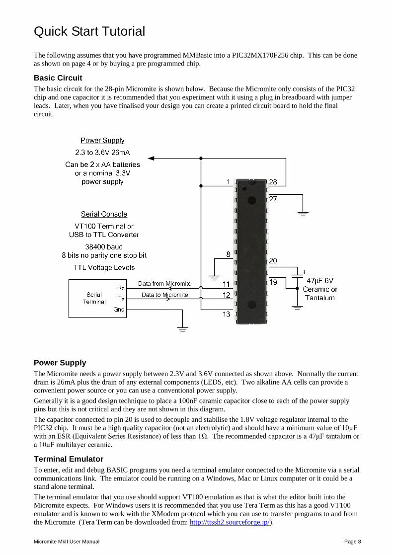
Quick Start Tutorial The following assumes that you have programmed MMBasic into a PIC32MX170F256 chip. This can be done as shown on page 4 or by buying a pre programmed chip.
Basic Circuit The basic circuit for the 28-pin Micromite is shown below. Because the Micromite only consists of the PIC32 chip and one capacitor it is recommended that you experiment with it using a plug in breadboard with jumper leads. Later, when you have finalised your design you can create a printed circuit board to hold the final circuit.
Power Supply The Micromite needs a power supply between 2.3V and 3.6V connected as shown above. Normally the current drain is 26mA plus the drain of any external components (LEDS, etc). Two alkaline AA cells can provide a convenient power source or you can use a conventional power supply. Generally it is a good design technique to place a 100nF ceramic capacitor close to each of the power supply pins but this is not critical and they are not shown in this diagram. The capacitor connected to pin 20 is used to decouple and stabilise the 1.8V voltage regulator internal to the PIC32 chip. It must be a high quality capacitor (not an electrolytic) and should have a minimum value of 10µF with an ESR (Equivalent Series Resistance) of less than 1Ω. The recommended capacitor is a 47µF tantalum or a 10µF multilayer ceramic.
Terminal Emulator To enter, edit and debug BASIC programs you need a terminal emulator connected to the Micromite via a serial communications link. The emulator could be running on a Windows, Mac or Linux computer or it could be a stand alone terminal. The terminal emulator that you use should support VT100 emulation as that is what the editor built into the Micromite expects. For Windows users it is recommended that you use Tera Term as this has a good VT100 emulator and is known to work with the XModem protocol which you can use to transfer programs to and from the Micromite (Tera Term can be downloaded from: http://ttssh2.sourceforge.jp/).
Micromite MkII User Manual Page 9
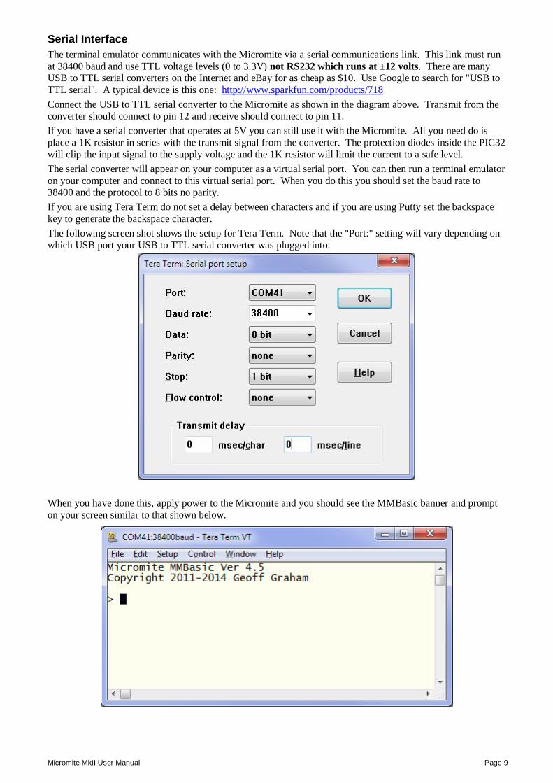
Serial Interface The terminal emulator communicates with the Micromite via a serial communications link. This link must run at 38400 baud and use TTL voltage levels (0 to 3.3V) not RS232 which runs at ±12 volts. There are many USB to TTL serial converters on the Internet and eBay for as cheap as $10. Use Google to search for "USB to TTL serial". A typical device is this one: http://www.sparkfun.com/products/718 Connect the USB to TTL serial converter to the Micromite as shown in the diagram above. Transmit from the converter should connect to pin 12 and receive should connect to pin 11. If you have a serial converter that operates at 5V you can still use it with the Micromite. All you need do is place a 1K resistor in series with the transmit signal from the converter. The protection diodes inside the PIC32 will clip the input signal to the supply voltage and the 1K resistor will limit the current to a safe level. The serial converter will appear on your computer as a virtual serial port. You can then run a terminal emulator on your computer and connect to this virtual serial port. When you do this you should set the baud rate to 38400 and the protocol to 8 bits no parity. If you are using Tera Term do not set a delay between characters and if you are using Putty set the backspace key to generate the backspace character. The following screen shot shows the setup for Tera Term. Note that the "Port:" setting will vary depending on which USB port your USB to TTL serial converter was plugged into.
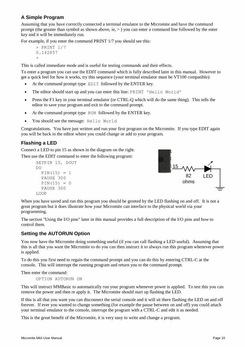
When you have done this, apply power to the Micromite and you should see the MMBasic banner and prompt on your screen similar to that shown below.
Micromite MkII User Manual Page 10
A Simple Program Assuming that you have correctly connected a terminal emulator to the Micromite and have the command prompt (the greater than symbol as shown above, ie, > ) you can enter a command line followed by the enter key and it will be immediately run. For example, if you enter the command PRINT 1/7 you should see this:
> PRINT 1/7 0.142857 >
This is called immediate mode and is useful for testing commands and their effects. To enter a program you can use the EDIT command which is fully described later in this manual. However to get a quick feel for how it works, try this sequence (your terminal emulator must be VT100 compatible): At the command prompt type EDIT followed by the ENTER key.
The editor should start up and you can enter this line: PRINT "Hello World"
Press the F1 key in your terminal emulator (or CTRL-Q which will do the same thing). This tells the editor to save your program and exit to the command prompt.
At the command prompt type RUN followed by the ENTER key.
You should see the message: Hello World
Congratulations. You have just written and run your first program on the Micromite. If you type EDIT again you will be back in the editor where you could change or add to your program.
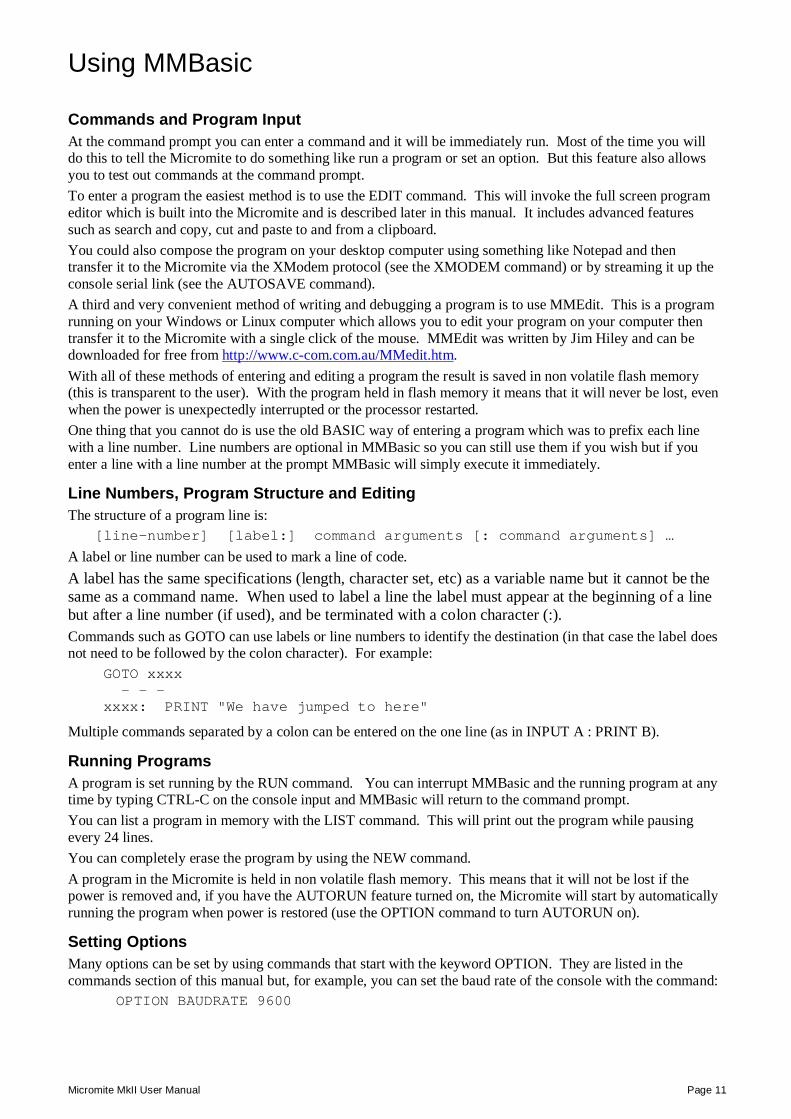
Flashing a LED Connect a LED to pin 15 as shown in the diagram on the right. Then use the EDIT command to enter the following program:
SETPIN 15, DOUT DO PIN(15) = 1 PAUSE 300 PIN(15) = 0 PAUSE 300 LOOP
When you have saved and run this program you should be greeted by the LED flashing on and off. It is not a great program but it does illustrate how your Micromite can interface to the physical world via your programming.
The section "Using the I/O pins" later in this manual provides a full description of the I/O pins and how to control them.
Setting the AUTORUN Option You now have the Micromite doing something useful (if you can call flashing a LED useful). Assuming that this is all that you want the Micromite to do you can then instruct it to always run this program whenever power is applied.
To do this you first need to regain the command prompt and you can do this by entering CTRL-C at the console. This will interrupt the running program and return you to the command prompt.
Then enter the command: OPTION AUTORUN ON
This will instruct MMBasic to automatically run your program whenever power is applied. To test this you can remove the power and then re apply it. The Micromite should start up flashing the LED.
If this is all that you want you can disconnect the serial console and it will sit there flashing the LED on and off forever. If ever you wanted to change something (for example the pause between on and off) you could attach your terminal emulator to the console, interrupt the program with a CTRL-C and edit it as needed.
This is the great benefit of the Micromite, it is very easy to write and change a program.
82 ohms
15
LED
Micromite MkII User Manual Page 11
Using MMBasic
Commands and Program Input At the command prompt you can enter a command and it will be immediately run. Most of the time you will do this to tell the Micromite to do something like run a program or set an option. But this feature also allows you to test out commands at the command prompt. To enter a program the easiest method is to use the EDIT command. This will invoke the full screen program editor which is built into the Micromite and is described later in this manual. It includes advanced features such as search and copy, cut and paste to and from a clipboard. You could also compose the program on your desktop computer using something like Notepad and then transfer it to the Micromite via the XModem protocol (see the XMODEM command) or by streaming it up the console serial link (see the AUTOSAVE command). A third and very convenient method of writing and debugging a program is to use MMEdit. This is a program running on your Windows or Linux computer which allows you to edit your program on your computer then transfer it to the Micromite with a single click of the mouse. MMEdit was written by Jim Hiley and can be downloaded for free from http://www.c-com.com.au/MMedit.htm. With all of these methods of entering and editing a program the result is saved in non volatile flash memory (this is transparent to the user). With the program held in flash memory it means that it will never be lost, even when the power is unexpectedly interrupted or the processor restarted. One thing that you cannot do is use the old BASIC way of entering a program which was to prefix each line with a line number. Line numbers are optional in MMBasic so you can still use them if you wish but if you enter a line with a line number at the prompt MMBasic will simply execute it immediately.
Line Numbers, Program Structure and Editing The structure of a program line is: [line-number] [label:] command arguments [: command arguments] …
A label or line number can be used to mark a line of code. A label has the same specifications (length, character set, etc) as a variable name but it cannot be the same as a command name. When used to label a line the label must appear at the beginning of a line but after a line number (if used), and be terminated with a colon character (:). Commands such as GOTO can use labels or line numbers to identify the destination (in that case the label does not need to be followed by the colon character). For example: GOTO xxxx - - - xxxx: PRINT "We have jumped to here"
Multiple commands separated by a colon can be entered on the one line (as in INPUT A : PRINT B).
Running Programs A program is set running by the RUN command. You can interrupt MMBasic and the running program at any time by typing CTRL-C on the console input and MMBasic will return to the command prompt. You can list a program in memory with the LIST command. This will print out the program while pausing every 24 lines. You can completely erase the program by using the NEW command. A program in the Micromite is held in non volatile flash memory. This means that it will not be lost if the power is removed and, if you have the AUTORUN feature turned on, the Micromite will start by automatically running the program when power is restored (use the OPTION command to turn AUTORUN on).
Setting Options Many options can be set by using commands that start with the keyword OPTION. They are listed in the commands section of this manual but, for example, you can set the baud rate of the console with the command:
OPTION BAUDRATE 9600
Micromite MkII User Manual Page 12
Shortcut Keys When you are using a VT100 compatible terminal emulator on the console you can use the function keys to insert a command at the command prompt. These shortcut keys are:
F2 RUN F3 LIST F4 EDIT F10 AUTOSAVE F11 XMODEM RECEIVE F12 XMODEM SEND
Pressing the key will insert the text at the command prompt, just as if it had been typed on the keyboard.
Differences from Previous Versions of MMBasic Readers who have used previous versions of MMBasic will find that there are a few differences from the Maximite versions of MMBasic. None of the changes are substantial and most have been made to accommodate the Micromite hardware and squeeze MMBasic in a smaller memory space. In summary, the changes are: Functions related to video output, keyboard input, USB, audio, the SD card or the internal drive A: are
not included.
The Micromite's program is stored in the internal flash memory and is not lost when the power is cycled.
The ability to enter a program at the command prompt by preceding each line with a line number is not available on the Micromite. Similarly the DELETE command is not available. To enter and modify programs on the Micromite use the full screen editor.
The SETPIN command now accepts mnemonic identifiers for the mode of the pin and these are much easier to remember. For example you can now specify SETPIN 14, DIN instead of SETPIN 14, 2. The old numbers are still accepted.
A new interrupt type has been added - you can now interrupt on any input change (hi to low or low to hi).
Some of the maximum numbers have been reduced. For example the maximum number of nested GOSUBs is now 30 (reduced from 100). This is to save on memory.
The AUTO command has been partially replaced with the AUTOSAVE command.
The LIST command has an option (LIST ALL) to list the program without stopping so that it can be captured by the terminal emulator connected to the console (an alternative method of transferring a program).
The OPTION and CONFIG commands have been merged to OPTION. New options have been added for the console baud rate, the AUTORUN feature and setting a security PIN.
The FORMAT$() function, and the WRITE command are not implemented. The STR$() function has been extended to replace some of the formatting functions previously provided by FORMAT$().
The CPU command has been added to change the processor speed or put it to sleep.
COM1: can now run at speeds up to 230400 and supports the enable signal and 9 bit data for IEEE 485. The new invert option allows direct interfacing to RS232 circuits. On both COM1: and COM2: the send buffer is fixed at 256 bytes (the receive buffer is still configurable).
The I2C commands have been renamed but have the same functionality. A string can now be used when receiving data. Master interrupts, the NUM2BYTE command and BYTE2NUM () function are not implemented (the PEEK function and POKE commands can be used to replace them).
The 1-Wire commands have been renamed but have the same functionality. You cannot use an array or string variable for 'data' and the reset command does not accept a 'presence' variable (use the MM.ONEWIRE variable instead). The OWCRC8() and OWCRC16() functions are not implemented.
The SPI command can now run with a clock speed up to 10MHz. The SPI function first needs to be opened and then closed when the function is no longer required. There is one SPI channel and it is fixed to a certain set of I/O pins.
There are five PWM channels in two groups and the frequency of each group can be set independently.
Micromite MkII User Manual Page 13
Micromite Special Features
Saved Variables Because the Micromite does not have a normal storage system (such as an SD card) it needs to have a facility to save some data that can be recovered when power is restored. This can be done with the VAR SAVE command which will take an unlimited number of variables on its command line and will save their values in non volatile flash memory. The space reserved for saved variables is 2KB. These variables can be restored with the VAR RESTORE command which will add all the saved variables to the variable table of the running program. Normally this command is placed near the start of a program so that the variables are ready for use by the program. This facility is intended for saving data such as calibration data, user selected options and other items which changed infrequently. It should not be used for high speed saves as you may wear out the flash memory. The flash in the PIC32MX170F256 series of chips has a very high endurance of over 20,000 writes and erases. With normal use this will never be reached but it can be exceeded by a program that repeatedly saves variables. For example, a program that saved a set of variables once a second would wear out the flash in six hours while a program that saved the same data once a day would run for over 50 years and still not wear out the flash. If you do want to save data often it would be worth adding a real time clock chip to the Micromite design. The RTC SETREG and RTC GETREG commands can then be used to store and retrieve data from the RTC's battery backed memory. See the RTC command for more details.
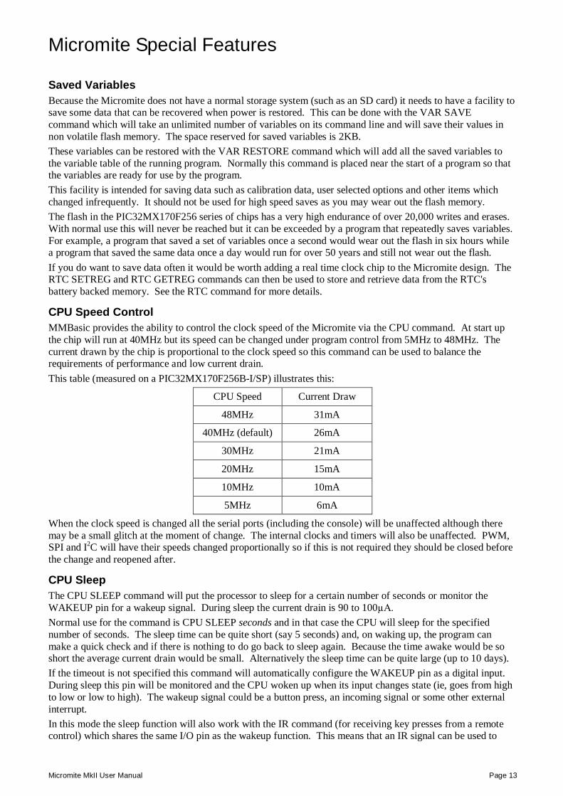
CPU Speed Control MMBasic provides the ability to control the clock speed of the Micromite via the CPU command. At start up the chip will run at 40MHz but its speed can be changed under program control from 5MHz to 48MHz. The current drawn by the chip is proportional to the clock speed so this command can be used to balance the requirements of performance and low current drain. This table (measured on a PIC32MX170F256B-I/SP) illustrates this:
CPU Speed Current Draw
48MHz 31mA
40MHz (default) 26mA
30MHz 21mA
20MHz 15mA
10MHz 10mA
5MHz 6mA
When the clock speed is changed all the serial ports (including the console) will be unaffected although there may be a small glitch at the moment of change. The internal clocks and timers will also be unaffected. PWM, SPI and I2C will have their speeds changed proportionally so if this is not required they should be closed before the change and reopened after.
CPU Sleep The CPU SLEEP command will put the processor to sleep for a certain number of seconds or monitor the WAKEUP pin for a wakeup signal. During sleep the current drain is 90 to 100µA. Normal use for the command is CPU SLEEP seconds and in that case the CPU will sleep for the specified number of seconds. The sleep time can be quite short (say 5 seconds) and, on waking up, the program can make a quick check and if there is nothing to do go back to sleep again. Because the time awake would be so short the average current drain would be small. Alternatively the sleep time can be quite large (up to 10 days). If the timeout is not specified this command will automatically configure the WAKEUP pin as a digital input. During sleep this pin will be monitored and the CPU woken up when its input changes state (ie, goes from high to low or low to high). The wakeup signal could be a button press, an incoming signal or some other external interrupt. In this mode the sleep function will also work with the IR command (for receiving key presses from a remote control) which shares the same I/O pin as the wakeup function. This means that an IR signal can be used to
Micromite MkII User Manual Page 14
wakeup the Micromite which will then immediately decode the signal. The program can then do whatever it needs to do in response to the remote control key press then go back to sleep and wait for the next command.
Watchdog Timer The main use for the Micromite is as an embedded controller. It can be programmed in MMBasic and when the program is debugged and ready for "prime time" the AUTORUN configuration setting can be turned on. The chip will then automatically run its program when power is applied and act as a custom integrated circuit performing some special task. The user need not know anything about what is running inside the chip. However there is the possibility that a fault in the program could cause MMBasic to generate an error and return to the command prompt. This would be of little use in an embedded situation as the Micromite would not have anything connected to the console. Another possibility is that the BASIC program could get itself stuck in an endless loop for some reason. In both cases the visible effect would be the same… the program would stop running until the power was cycled. To guard against this the watchdog timer should be used. This is a timer that counts down to zero and when it reaches zero the processor will be automatically restarted (the same as when power was first applied), even if MMBasic was sitting at the command prompt. The automatic variable MM.WATCHDOG will also be set to true to indicate that the restart was caused by a watchdog timeout. The WATCHDOG command should be placed in strategic locations in the program to keep resetting the timer and therefore preventing it from counting down to zero. Then, if a fault occurs, the timer will not be reset, it will reach zero and the program will be restarted (assuming the AUTORUN option is set).
PIN Security Sometimes it is important to keep the data and program in an embedded controller confidential. In the Micromite this can be done by using the OPTION PIN command. This command will set a pin number (which is stored in flash) and whenever the Micromite returns to the command prompt (for whatever reason) the user at the console will be prompted to enter the PIN number. Without the correct PIN the user cannot get to the command prompt and their only option is to enter the correct PIN or reboot the Micromite. When it is rebooted the user will still need the correct PIN to access the command prompt. Because an intruder cannot reach the command prompt they cannot list or copy a program, they cannot change the program or change any aspect of MMBasic or the Micromite. Once set the PIN can only be removed by providing the correct PIN as set in the first place. If the number is lost the only method of recovery is to reset MMBasic as described below (which will erase the program). There are other time consuming ways of accessing the data (such as using a PIC32 programmer to examine the flash memory) so this should not be regarded as the ultimate security but it does act as a significant deterrent.
The Serial Console Using the OPTION BAUDRATE command the baud rate of the console can be changed to any speed up to 230400 bps. Changing the console baud rate to a higher speed makes the full screen editor much faster in redrawing the screen. If you have a reliable connection to the Micromite it is worth changing the speed to at least 115200. When running as an embedded controller the serial console may no longer be required for programming. It can then be used as a third serial port and OPTION BAUDRATE used to set the required speed. If you do this it might be worth using the OPTION BREAK command to disable the break key to prevent an unintended CTRL-C in the console receive data from halting the running program. Other useful options are OPTION CONSOLE NOECHO which will stop MMBasic from automatically echoing characters received on the console and OPTION CONSOLE INVERT which will invert the data on the transmit and receive lines so that it can be used with RS232 devices. Once changed the console baud rate will be permanently remembered unless another OPTION BAUDRATE command is used to change it. Using this command it is possible to accidently set the baud rate to an invalid speed and in that case the only recovery is to reset MMBasic as described below.
Resetting MMBasic MMBasic can be reset to its original configuration using either one of two methods: The chip can be reprogrammed with the Micromite firmware using a PIC32 programmer.
It can be reset by joining the console Tx and Rx pins together and then applying power. Following this, wait a couple of seconds then remove the power followed by the link joining the two pins.
Micromite MkII User Manual Page 15
Either method will result in the program memory and saved variables being completely erased and all options (security PIN, console baud rate, etc) will be reset to their initial defaults.
64-bit Integers MMBasic on the Micromite MkII supports 64-bit integers in addition to floating point. These can be used to store and manipulate very large numbers up to 19 digits (± 9223372036854775807 to be precise) without loss of accuracy (as against floating point which has a limit of about 7 significant digits). Integers are also slightly faster (about 25%) than floating point. Integers can be specified by adding the suffix "%" to a variable's name (eg, count%, j%, etc) and by using constants without a decimal point. When working with integers it is best to keep all variables and numbers involved in the calculations defined as integers however you can mix the two if needed (with possible loss of precision). See the section "Defining and Using Variables" which provides more detail on this subject. MMBasic with 64-bit integers is fully backwards compatible with programs written for earlier versions so they can run unchanged. For normal use 64-bit integers can be ignored however some applications, especially programs involved in communicating with other chips, will benefit from this level of precision while manipulating large numbers.
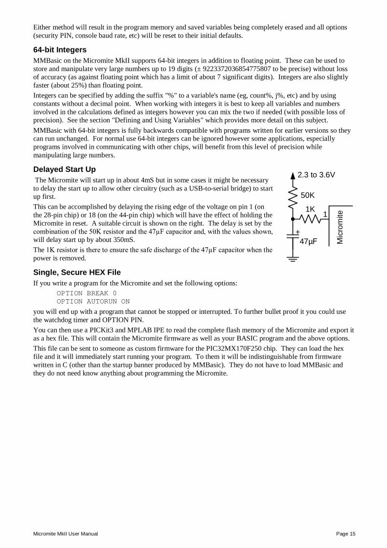
Delayed Start Up The Micromite will start up in about 4mS but in some cases it might be necessary to delay the start up to allow other circuitry (such as a USB-to-serial bridge) to start up first. This can be accomplished by delaying the rising edge of the voltage on pin 1 (on the 28-pin chip) or 18 (on the 44-pin chip) which will have the effect of holding the Micromite in reset. A suitable circuit is shown on the right. The delay is set by the combination of the 50K resistor and the 47µF capacitor and, with the values shown, will delay start up by about 350mS. The 1K resistor is there to ensure the safe discharge of the 47µF capacitor when the power is removed.
Single, Secure HEX File If you write a program for the Micromite and set the following options:
OPTION BREAK 0 OPTION AUTORUN ON
you will end up with a program that cannot be stopped or interrupted. To further bullet proof it you could use the watchdog timer and OPTION PIN. You can then use a PICKit3 and MPLAB IPE to read the complete flash memory of the Micromite and export it as a hex file. This will contain the Micromite firmware as well as your BASIC program and the above options. This file can be sent to someone as custom firmware for the PIC32MX170F250 chip. They can load the hex file and it will immediately start running your program. To them it will be indistinguishable from firmware written in C (other than the startup banner produced by MMBasic). They do not have to load MMBasic and they do not need know anything about programming the Micromite.
50K
2.3 to 3.6V
1
Mic
rom
ite
+ 47µF
1K
Micromite MkII User Manual Page 16
Special Hardware Devices
To make it easier for a program to interact with the external world the Micromite includes drivers for a number of common peripheral devices.
These are:
Infrared remote control receiver and transmitter The DS18B20 temperature sensor and DHT22 temperature/humidity sensor LCD display modules Numeric keypads Battery backed clock Servos Ultrasonic distance sensor
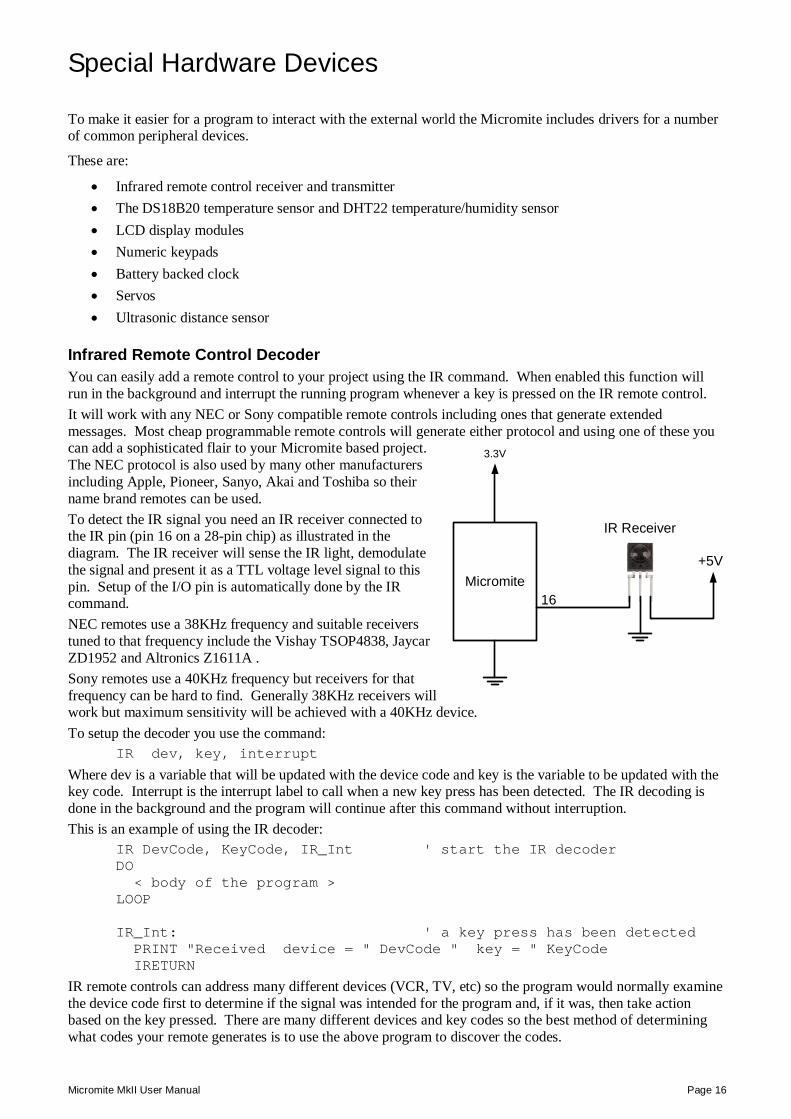
Infrared Remote Control Decoder You can easily add a remote control to your project using the IR command. When enabled this function will run in the background and interrupt the running program whenever a key is pressed on the IR remote control. It will work with any NEC or Sony compatible remote controls including ones that generate extended messages. Most cheap programmable remote controls will generate either protocol and using one of these you can add a sophisticated flair to your Micromite based project. The NEC protocol is also used by many other manufacturers including Apple, Pioneer, Sanyo, Akai and Toshiba so their name brand remotes can be used. To detect the IR signal you need an IR receiver connected to the IR pin (pin 16 on a 28-pin chip) as illustrated in the diagram. The IR receiver will sense the IR light, demodulate the signal and present it as a TTL voltage level signal to this pin. Setup of the I/O pin is automatically done by the IR command. NEC remotes use a 38KHz frequency and suitable receivers tuned to that frequency include the Vishay TSOP4838, Jaycar ZD1952 and Altronics Z1611A . Sony remotes use a 40KHz frequency but receivers for that frequency can be hard to find. Generally 38KHz receivers will work but maximum sensitivity will be achieved with a 40KHz device. To setup the decoder you use the command:
IR dev, key, interrupt
Where dev is a variable that will be updated with the device code and key is the variable to be updated with the key code. Interrupt is the interrupt label to call when a new key press has been detected. The IR decoding is done in the background and the program will continue after this command without interruption. This is an example of using the IR decoder:
IR DevCode, KeyCode, IR_Int ' start the IR decoder DO < body of the program > LOOP IR_Int: ' a key press has been detected PRINT "Received device = " DevCode " key = " KeyCode IRETURN
IR remote controls can address many different devices (VCR, TV, etc) so the program would normally examine the device code first to determine if the signal was intended for the program and, if it was, then take action based on the key pressed. There are many different devices and key codes so the best method of determining what codes your remote generates is to use the above program to discover the codes.
+5VMicromite
3.3V
16
IR Receiver
Micromite MkII User Manual Page 17
The IR function uses the same I/O pin as the wakeup signal for the CPU SLEEP command and it is possible to combine them so that an incoming IR signal will wake the Micromite which will then decode the IR signal. In this way you can have a Micromite running on battery power that will wake up on an IR signal, do something based on the signal, then go back to sleep. The following is an example:
IR DevCode, KeyCode, IR_Int ' start the IR decoder DO CPU SLEEP ' now sleep until a signal LOOP IR_Int: ' a key press has been detected < do some work based on the key press > IRETURN ' return to sleep again
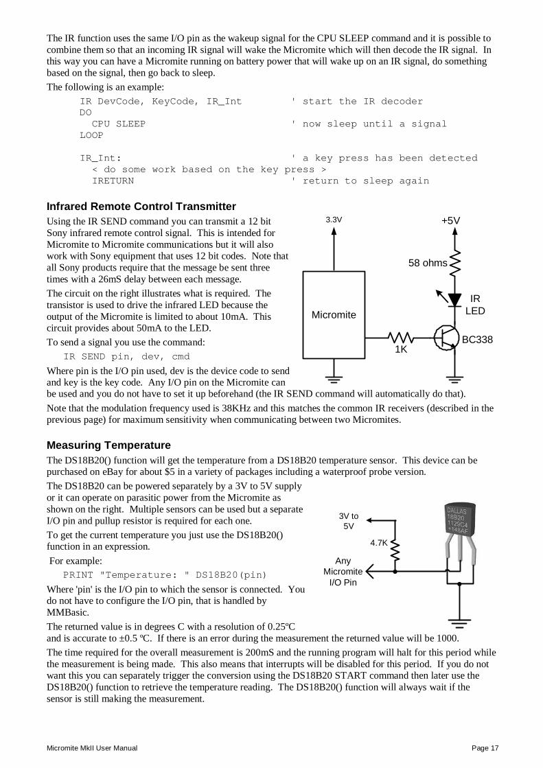
Infrared Remote Control Transmitter Using the IR SEND command you can transmit a 12 bit Sony infrared remote control signal. This is intended for Micromite to Micromite communications but it will also work with Sony equipment that uses 12 bit codes. Note that all Sony products require that the message be sent three times with a 26mS delay between each message. The circuit on the right illustrates what is required. The transistor is used to drive the infrared LED because the output of the Micromite is limited to about 10mA. This circuit provides about 50mA to the LED. To send a signal you use the command:
IR SEND pin, dev, cmd
Where pin is the I/O pin used, dev is the device code to send and key is the key code. Any I/O pin on the Micromite can be used and you do not have to set it up beforehand (the IR SEND command will automatically do that). Note that the modulation frequency used is 38KHz and this matches the common IR receivers (described in the previous page) for maximum sensitivity when communicating between two Micromites.
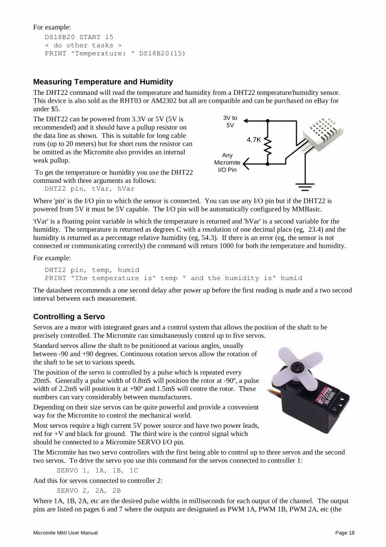
Measuring Temperature The DS18B20() function will get the temperature from a DS18B20 temperature sensor. This device can be purchased on eBay for about $5 in a variety of packages including a waterproof probe version. The DS18B20 can be powered separately by a 3V to 5V supply or it can operate on parasitic power from the Micromite as shown on the right. Multiple sensors can be used but a separate I/O pin and pullup resistor is required for each one. To get the current temperature you just use the DS18B20() function in an expression. For example:
PRINT "Temperature: " DS18B20(pin)
Where 'pin' is the I/O pin to which the sensor is connected. You do not have to configure the I/O pin, that is handled by MMBasic. The returned value is in degrees C with a resolution of 0.25ºC and is accurate to ±0.5 ºC. If there is an error during the measurement the returned value will be 1000. The time required for the overall measurement is 200mS and the running program will halt for this period while the measurement is being made. This also means that interrupts will be disabled for this period. If you do not want this you can separately trigger the conversion using the DS18B20 START command then later use the DS18B20() function to retrieve the temperature reading. The DS18B20() function will always wait if the sensor is still making the measurement.
AnyMicromite
I/O Pin
4.7K
3V to 5V
3.3V
1K
58 ohms
+5V
BC338
IR LEDMicromite
Micromite MkII User Manual Page 18
For example: DS18B20 START 15 < do other tasks > PRINT "Temperature: " DS18B20(15)
Measuring Temperature and Humidity The DHT22 command will read the temperature and humidity from a DHT22 temperature/humidity sensor. This device is also sold as the RHT03 or AM2302 but all are compatible and can be purchased on eBay for under $5. The DHT22 can be powered from 3.3V or 5V (5V is recommended) and it should have a pullup resistor on the data line as shown. This is suitable for long cable runs (up to 20 meters) but for short runs the resistor can be omitted as the Micromite also provides an internal weak pullup.
To get the temperature or humidity you use the DHT22 command with three arguments as follows:
DHT22 pin, tVar, hVar
Where 'pin' is the I/O pin to which the sensor is connected. You can use any I/O pin but if the DHT22 is powered from 5V it must be 5V capable. The I/O pin will be automatically configured by MMBasic.
'tVar' is a floating point variable in which the temperature is returned and 'hVar' is a second variable for the humidity. The temperature is returned as degrees C with a resolution of one decimal place (eg, 23.4) and the humidity is returned as a percentage relative humidity (eg, 54.3). If there is an error (eg, the sensor is not connected or communicating correctly) the command will return 1000 for both the temperature and humidity.
For example: DHT22 pin, temp, humid PRINT "The temperature is" temp " and the humidity is" humid
The datasheet recommends a one second delay after power up before the first reading is made and a two second interval between each measurement.
Controlling a Servo Servos are a motor with integrated gears and a control system that allows the position of the shaft to be precisely controlled. The Micromite can simultaneously control up to five servos. Standard servos allow the shaft to be positioned at various angles, usually between -90 and +90 degrees. Continuous rotation servos allow the rotation of the shaft to be set to various speeds. The position of the servo is controlled by a pulse which is repeated every 20mS. Generally a pulse width of 0.8mS will position the rotor at -90º, a pulse width of 2.2mS will position it at +90º and 1.5mS will centre the rotor. These numbers can vary considerably between manufacturers. Depending on their size servos can be quite powerful and provide a convenient way for the Micromite to control the mechanical world. Most servos require a high current 5V power source and have two power leads, red for +V and black for ground. The third wire is the control signal which should be connected to a Micromite SERVO I/O pin. The Micromite has two servo controllers with the first being able to control up to three servos and the second two servos. To drive the servo you use this command for the servos connected to controller 1:
SERVO 1, 1A, 1B, 1C
And this for servos connected to controller 2: SERVO 2, 2A, 2B
Where 1A, 1B, 2A, etc are the desired pulse widths in milliseconds for each output of the channel. The output pins are listed on pages 6 and 7 where the outputs are designated as PWM 1A, PWM 1B, PWM 2A, etc (the
AnyMicromite
I/O Pin
4.7K
3V to 5V
Micromite MkII User Manual Page 19
PWM and SERVO commands are closely related and use the same I/O pins). If you want to control less than this number of servos you can leave the unused output off the list and use that pin as a general purpose I/O. The pulse width can be specified with a high resolution (about 0.005 mS). For example, the following will position the rotor of the servo connected to channel 1A to near its centre:
SERVO 1, 1.525
Following the SERVO command the Micromite will generate a continuous stream of pulses in the background until another servo command is given or the STOP option is used (which will terminate the output). As another example, the following will swing two servos back and forth alternatively every 5 seconds: These servos should be connected to the outputs PWM 1A and PWM 1B.
DO SERVO 1, 0.8, 2.2 PAUSE 5000 SERVO 1, 2.2, 0.8 PAUSE 5000 LOOP
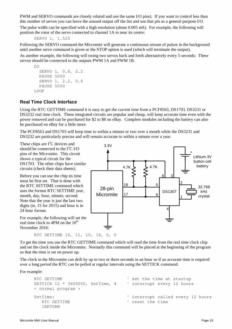
Real Time Clock Interface Using the RTC GETTIME command it is easy to get the current time from a PCF8563, DS1703, DS3231 or DS3232 real time clock. These integrated circuits are popular and cheap, will keep accurate time even with the power removed and can be purchased for $2 to $8 on eBay. Complete modules including the battery can also be purchased on eBay for a little more.
The PCF8563 and DS1703 will keep time to within a minute or two over a month while the DS3231 and DS3232 are particularly precise and will remain accurate to within a minute over a year.
These chips are I2C devices and should be connected to the I2C I/O pins of the Micromite. This circuit shows a typical circuit for the DS1703. The other chips have similar circuits (check their data sheets).
Before you can use the chip its time must be first set. That is done with the RTC SETTIME command which uses the format RTC SETTIME year, month, day, hour, minute, second. Note that the year is just the last two digits (ie, 15 for 2015) and hour is in 24 hour format.
For example, the following will set the real time clock to 4PM on the 10th November 2016:
RTC SETTIME 16, 11, 10, 16, 0, 0
To get the time you use the RTC GETTIME command which will read the time from the real time clock chip and set the clock inside the Micromite. Normally this command will be placed at the beginning of the program so that the time is set on power up.
The clock in the Micromite can drift by up to two or three seconds in an hour so if an accurate time is required over a long period the RTC can be polled at regular intervals using the SETTICK command.
For example: RTC GETTIME ' set the time at startup SETTICK 12 * 3600000, SetTime, 4 ' interrupt every 12 hours < normal program > SetTime: ' interrupt called every 12 hours RTC GETTIME ' reset the time IRETURN
28-pinMicromite
DS1307
4.7K 4.7K
18
17
32.768kHz
crystal
+Lithium 3V button cell
battery
5
6
4
3
2
1
3.3V
8
Micromite MkII User Manual Page 20
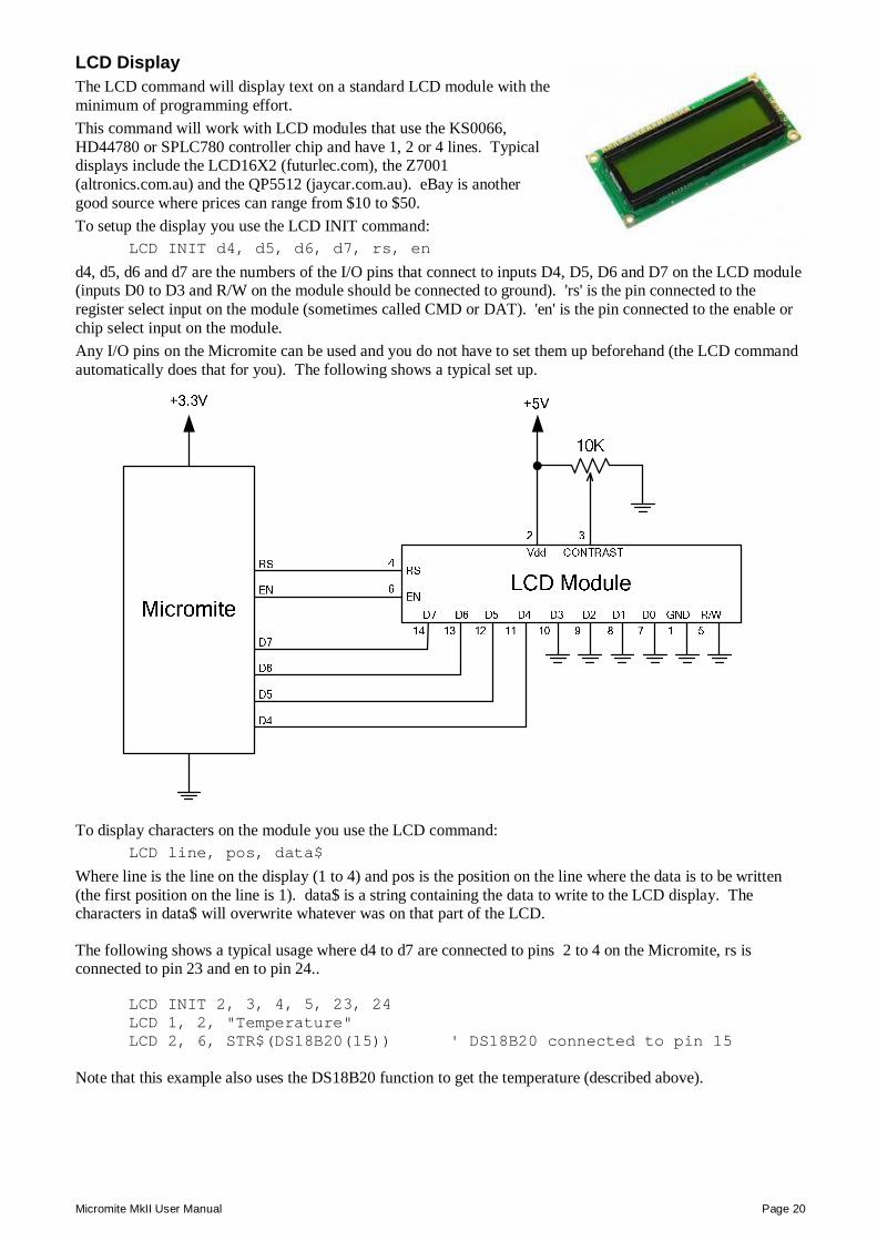
LCD Display The LCD command will display text on a standard LCD module with the minimum of programming effort. This command will work with LCD modules that use the KS0066, HD44780 or SPLC780 controller chip and have 1, 2 or 4 lines. Typical displays include the LCD16X2 (futurlec.com), the Z7001 (altronics.com.au) and the QP5512 (jaycar.com.au). eBay is another good source where prices can range from $10 to $50. To setup the display you use the LCD INIT command:
LCD INIT d4, d5, d6, d7, rs, en
d4, d5, d6 and d7 are the numbers of the I/O pins that connect to inputs D4, D5, D6 and D7 on the LCD module (inputs D0 to D3 and R/W on the module should be connected to ground). 'rs' is the pin connected to the register select input on the module (sometimes called CMD or DAT). 'en' is the pin connected to the enable or chip select input on the module. Any I/O pins on the Micromite can be used and you do not have to set them up beforehand (the LCD command automatically does that for you). The following shows a typical set up.
To display characters on the module you use the LCD command: LCD line, pos, data$
Where line is the line on the display (1 to 4) and pos is the position on the line where the data is to be written (the first position on the line is 1). data$ is a string containing the data to write to the LCD display. The characters in data$ will overwrite whatever was on that part of the LCD.
The following shows a typical usage where d4 to d7 are connected to pins 2 to 4 on the Micromite, rs is connected to pin 23 and en to pin 24..
LCD INIT 2, 3, 4, 5, 23, 24 LCD 1, 2, "Temperature" LCD 2, 6, STR$(DS18B20(15)) ' DS18B20 connected to pin 15
Note that this example also uses the DS18B20 function to get the temperature (described above).
Micromite MkII User Manual Page 21
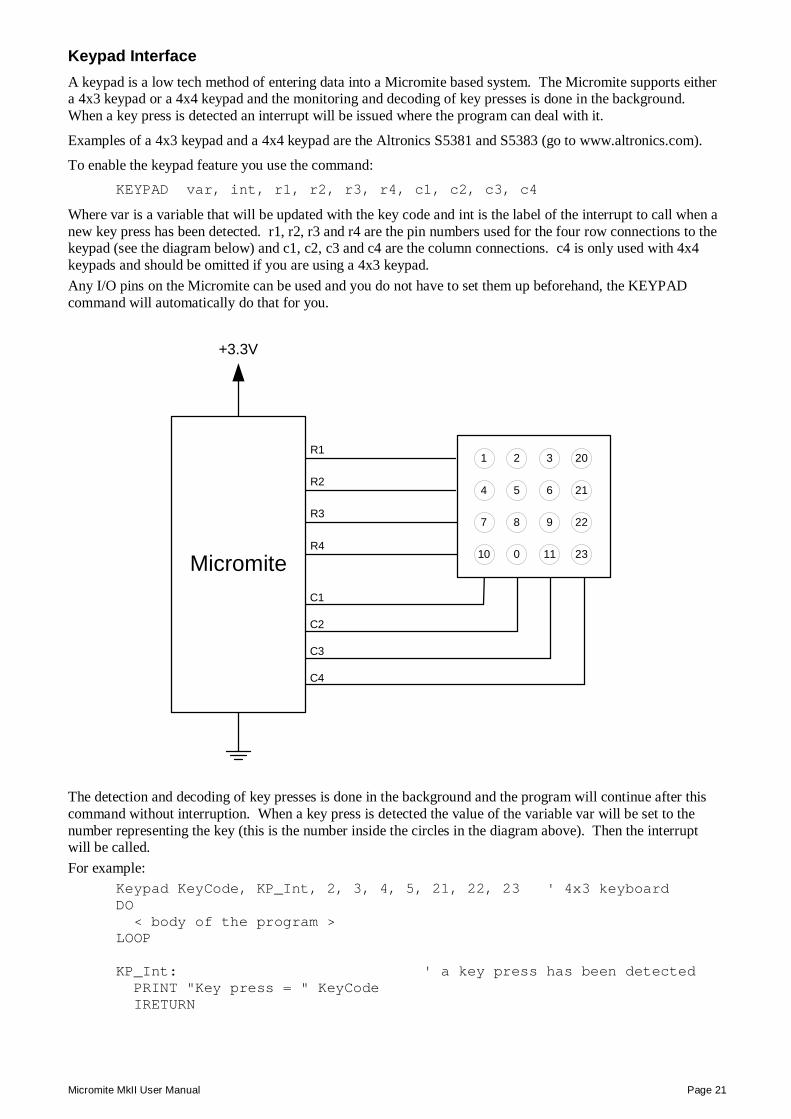
Keypad Interface A keypad is a low tech method of entering data into a Micromite based system. The Micromite supports either a 4x3 keypad or a 4x4 keypad and the monitoring and decoding of key presses is done in the background. When a key press is detected an interrupt will be issued where the program can deal with it.
Examples of a 4x3 keypad and a 4x4 keypad are the Altronics S5381 and S5383 (go to www.altronics.com).
To enable the keypad feature you use the command: KEYPAD var, int, r1, r2, r3, r4, c1, c2, c3, c4
Where var is a variable that will be updated with the key code and int is the label of the interrupt to call when a new key press has been detected. r1, r2, r3 and r4 are the pin numbers used for the four row connections to the keypad (see the diagram below) and c1, c2, c3 and c4 are the column connections. c4 is only used with 4x4 keypads and should be omitted if you are using a 4x3 keypad. Any I/O pins on the Micromite can be used and you do not have to set them up beforehand, the KEYPAD command will automatically do that for you.
C1
C2
C3
C4
+3.3V
10 0 11 23
7 8 9 22
4 5 6 21
1 2 3 20
Micromite
R1
R2
R3
R4
The detection and decoding of key presses is done in the background and the program will continue after this command without interruption. When a key press is detected the value of the variable var will be set to the number representing the key (this is the number inside the circles in the diagram above). Then the interrupt will be called. For example:
Keypad KeyCode, KP_Int, 2, 3, 4, 5, 21, 22, 23 ' 4x3 keyboard DO < body of the program > LOOP KP_Int: ' a key press has been detected PRINT "Key press = " KeyCode IRETURN
Micromite MkII User Manual Page 22
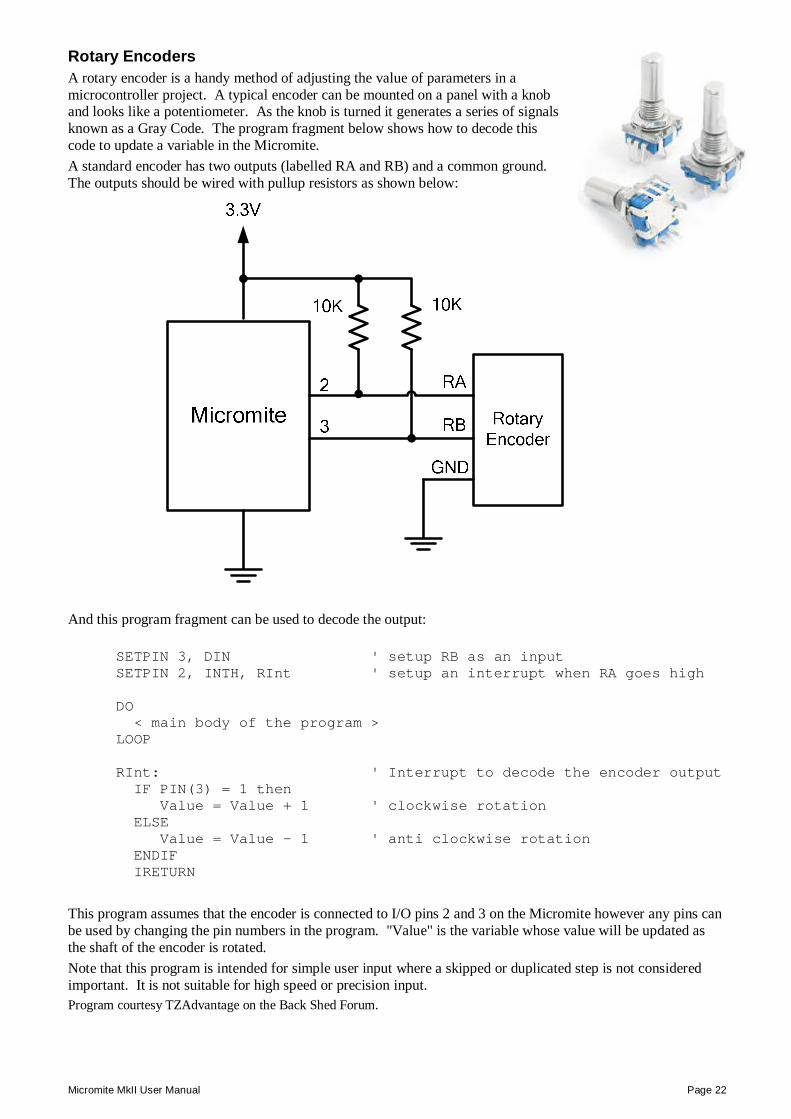
Rotary Encoders A rotary encoder is a handy method of adjusting the value of parameters in a microcontroller project. A typical encoder can be mounted on a panel with a knob and looks like a potentiometer. As the knob is turned it generates a series of signals known as a Gray Code. The program fragment below shows how to decode this code to update a variable in the Micromite. A standard encoder has two outputs (labelled RA and RB) and a common ground. The outputs should be wired with pullup resistors as shown below:
And this program fragment can be used to decode the output:
SETPIN 3, DIN ' setup RB as an input SETPIN 2, INTH, RInt ' setup an interrupt when RA goes high DO < main body of the program > LOOP RInt: ' Interrupt to decode the encoder output IF PIN(3) = 1 then Value = Value + 1 ' clockwise rotation ELSE Value = Value - 1 ' anti clockwise rotation ENDIF IRETURN
This program assumes that the encoder is connected to I/O pins 2 and 3 on the Micromite however any pins can be used by changing the pin numbers in the program. "Value" is the variable whose value will be updated as the shaft of the encoder is rotated. Note that this program is intended for simple user input where a skipped or duplicated step is not considered important. It is not suitable for high speed or precision input. Program courtesy TZAdvantage on the Back Shed Forum.
Micromite MkII User Manual Page 23
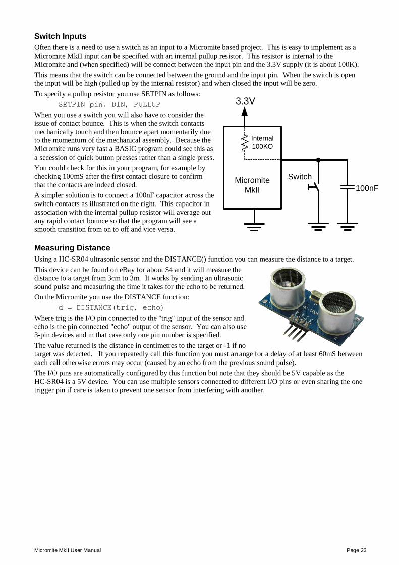
Switch Inputs Often there is a need to use a switch as an input to a Micromite based project. This is easy to implement as a Micromite MkII input can be specified with an internal pullup resistor. This resistor is internal to the Micromite and (when specified) will be connect between the input pin and the 3.3V supply (it is about 100K). This means that the switch can be connected between the ground and the input pin. When the switch is open the input will be high (pulled up by the internal resistor) and when closed the input will be zero. To specify a pullup resistor you use SETPIN as follows:
SETPIN pin, DIN, PULLUP
When you use a switch you will also have to consider the issue of contact bounce. This is when the switch contacts mechanically touch and then bounce apart momentarily due to the momentum of the mechanical assembly. Because the Micromite runs very fast a BASIC program could see this as a secession of quick button presses rather than a single press. You could check for this in your program, for example by checking 100mS after the first contact closure to confirm that the contacts are indeed closed. A simpler solution is to connect a 100nF capacitor across the switch contacts as illustrated on the right. This capacitor in association with the internal pullup resistor will average out any rapid contact bounce so that the program will see a smooth transition from on to off and vice versa.
Measuring Distance Using a HC-SR04 ultrasonic sensor and the DISTANCE() function you can measure the distance to a target. This device can be found on eBay for about $4 and it will measure the distance to a target from 3cm to 3m. It works by sending an ultrasonic sound pulse and measuring the time it takes for the echo to be returned. On the Micromite you use the DISTANCE function:
d = DISTANCE(trig, echo)
Where trig is the I/O pin connected to the "trig" input of the sensor and echo is the pin connected "echo" output of the sensor. You can also use 3-pin devices and in that case only one pin number is specified. The value returned is the distance in centimetres to the target or -1 if no target was detected. If you repeatedly call this function you must arrange for a delay of at least 60mS between each call otherwise errors may occur (caused by an echo from the previous sound pulse). The I/O pins are automatically configured by this function but note that they should be 5V capable as the HC-SR04 is a 5V device. You can use multiple sensors connected to different I/O pins or even sharing the one trigger pin if care is taken to prevent one sensor from interfering with another.
3.3V
Micromite MkII
Switch100nF
Internal100KO
Micromite MkII User Manual Page 24
Full Screen Editor
An important productivity feature of the Micromite is the full screen editor. This will work with any VT100 compatible terminal emulator (Tera Term is recommended).
The full screen program editor is invoked with the EDIT command. The cursor will be automatically positioned at the last place that you were editing at or, if your program had just been stopped by an error, the cursor will be positioned at the line that caused the error.
If you are used to an editor like Notepad you will find that the operation of this editor is familiar. The arrow keys will move your cursor around in the text, home and end will take you to the beginning or end of the line. Page up and page down will do what their titles suggest. The delete key will delete the character at the cursor and backspace will delete the character before the cursor. The insert key will toggle between insert and overtype modes.
About the only unusual key combination is that two home key presses will take you to the start of the program and two end key presses will take you to the end.
At the bottom of the screen the status line will list the various function keys used by the editor and their action. In more details these are:
ESC This will cause the editor to abandon all changes and return to the command prompt with the program memory unchanged. If you have changed the text you will be asked if you really what want to abandon your changes.
F1: SAVE This will save the program to program memory and return to the command prompt.
F2: RUN This will save the program to program memory and immediately run it.
F3: FIND This will prompt for the text that you want to search for. When you press enter the cursor will be placed at the start of the first entry found.
SHIFT-F3 Once you have used the search function you can repeatedly search for the same text by pressing SHIFT-F3.
F4: MARK This is described in detail below.
F5: PASTE This will insert (at the current cursor position) the text that had been previously cut or copied (see below).
Micromite MkII User Manual Page 25
If you pressed the mark key (F4) the editor will change to the mark mode. In this mode you can use the arrow keys to mark a section of text which will be highlighted in reverse video. You can then delete, cut or copy the marked text. In this mode the status line will change to show the functions of the function keys in the mark mode. These keys are:
ESC Will exit mark mode without changing anything.
F4: CUT Will copy the marked text to the clipboard and remove it from the program.
F5: COPY Will just copy the marked text to the clipboard.
DELETE Will delete the marked text leaving the clipboard unchanged.
You can also use control keys instead of the functions keys listed above. These control keystrokes are:
LEFT Ctrl-S RIGHT Ctrl-D UP Ctrl-E DOWN Ctrl-X HOME Ctrl-U END Ctrl-K PageUp Ctrl-P PageDn Ctrl-L DEL Ctrl-] INSERT Ctrl-N F1 Ctrl-Q F2 Ctrl-W F3 Ctrl-R ShiftF3 Ctrl-G F4 Ctrl-T F5 Ctrl-Y
The best way to learn the full screen editor is to simply fire it up and experiment.
The editor is a very productive method of writing a program. With the command EDIT you can write your program on the Micromite. Then, by pressing the F2 key, you can save and run the program. If your program stops with an error you can press the function key F4 which will run the command EDIT and place you back in the editor with the cursor positioned at the line that caused the error. This edit/run/edit cycle is very fast.
Using the OPTION BAUDRATE command the baud rate of the console can be changed to any speed up to 230400 bps. Changing the console baud rate to a higher speed makes the full screen editor much faster in redrawing the screen. If you have a reliable connection to the Micromite it is worth changing the speed to at least 115200. The editor expects that the terminal emulator is set to 24 lines per screen with each line 80 characters wide. Both of these assumptions can be changed with the OPTION DISPLAY command to suit non standard displays.
Note that a terminal emulator can lose its position in the text with multiple fast keystrokes (like the up and down arrows). If this happens you can press the HOME key twice which will force the editor to jump to the start of the program and redraw the display.
Micromite MkII User Manual Page 26
Defining and Using Variables Variables are a way for a program to store numbers or text, MMBasic on the Micromite MkII supports three different types of variables:
1. Floating point. These can store a number with a decimal point and fraction (eg, 45.386) and also very large numbers. However, they will loose accuracy when more than seven significant digits are stored or manipulated. Floating point variables are specified by adding the suffix '!' to a variable's name (eg, i!, nbr!, etc). They are also the default when a variable is created without a suffix (eg, i, nbr, etc).
2. 64-bit signed integer. These can store positive or negative numbers with up to 19 decimal digits without loosing accuracy but they cannot store fractions (ie, the part following the decimal point). These are specified by adding the suffix '%' to a variable's name. For example, i%, nbr%, etc. Note that during arithmetic operations (particularly addition and multiplication) no check is made for an overflow which may result in the final value requiring more than the number of digits supported. In that case the result will be nonsense.
3. Strings. These will store a string of characters (eg, "Tom"). String variable names are terminated with a '$' symbol (eg, name$, s$, etc). Strings can be up to 255 characters long.
Note that in previous versions of MMBasic it was legal to use the same variable name with different types and they would be different. For example, the following was accepted (and also led to obscure bugs):
Nbr = 123 Nbr$ = "abcd"
In version 4.6 and later of MMBasic this is illegal. If you try to use Nbr$ an error would be raised stating that the variable has already been defined with a different type (ie, floating point). Most programs use floating point variables as these can deal with the numbers used in typical situations and are more intuitive when dealing with division and fractions. So, if you are not bothered with the details, always use floating point. When a constant number is used it will be assumed that it is an integer if a decimal point or exponent is not used. For example, 1234 will be interpreted as an integer and 1234.0 will be interpreted as a floating point number. String constants are always surrounded by double quote marks (eg, "text string").
OPTION DEFAULT A variable can be used without a suffix (ie, !, % or $) and in that case MMBasic will use the default type of floating point. For example, the following will create a floating point variable:
Nbr = 1234
However the default can be changed with the OPTION DEFAULT command. For example, OPTION DEFAULT INTEGER will specify that all variables without a specific type will be integer. So, the following will create an integer variable:
OPTION DEFAULT INTEGER Nbr = 1234
The default can be set to FLOAT (which is the default when a program is run), INTEGER, STRING or NONE. In the latter case all variables must be specifically typed otherwise an error will occur. The OPTION DEFAULT command can be placed anywhere in the program and changed at any time but good practice dictates that if it is used it should be placed at the start of the program and left unchanged.
OPTION EXPLICIT By default MMBasic will automatically create a variable when it is first referenced. So, Nbr = 1234 will create the variable and set it to the number 1234 at the same time. This is convenient for short and quick programs but it can lead to subtle and difficult to find bugs in large programs. For example, in the third line of this fragment the variable Nbr has been misspelt as Nr. As a consequence the variable Nr would be created with a value of zero and the value of Total would be wrong.
Nbr = 1234 Incr = 2 Total = Nr + Incr
Micromite MkII User Manual Page 27
The OPTION EXPLICIT command tells MMBasic to disallow the automatic creation of variables. Instead they must be explicitly defined beforehand using the DIM or LOCAL commands (see below). If the OPTION EXPLICIT command was used as shown below the error would become obvious when the program was run:
> LIST OPTION EXPLICIT DIM Nbr, Incr, Total Nbr = 1234 Incr = 2 Total = Nr + Incr > > RUN [5] Total = Nr + Incr Error: Variable not declared >
The use of OPTION EXPLICIT is recommended to support good programming practice. If it is used it should be placed at the start of the program before any variables are used.
DIM and LOCAL The DIM and LOCAL commands can be used to define a variable and set its type and are mandatory when the OPTION EXPLICIT command is used. The DIM command will create a global variable that can be seen and used throughout the program including inside subroutines and functions. However, if you require that the definition will be visible only within the subroutine or function, you should use the LOCAL command. LOCAL has exactly the same syntax as DIM. If LOCAL is used to specify a variable with the same name as a global variable then the global variable will be hidden to the subroutine or function and any references to the variable will only refer to the variable defined by the LOCAL command. At its simplest level DIM and LOCAL can be used to define one or more variables based on their type suffix or the OPTION DEFAULT in force at the time. For example:
DIM nbr%, str$
But it can also be used to define one or more variables with a specific type when the type suffix is not used: DIM INTEGER nbr, nbr2, nbr3, etc
In this case nbr, nbr2, nbr3, etc are all created as integers. When you use the variable within a program you do not need to specify the type suffix. For example, the following works as expected:
nbr2 = 12345678
The DIM and LOCAL commands will also accept the Microsoft practice of specifying the variable's type after the variable with the keyword "AS". For example:
DIM nbr AS INTEGER, str AS STRING
In this case the type of each variable is set individually (not as a group as when the type is placed before the list of variables).
The commands can also be used to initialise a variable while it is being defined. For example: DIM INTEGER a = 5, b = 4, c = 3 DIM s$ = "World", i% = &FHHHHHHH DIM str AS STRING = "Hello" + " " + s$
Note that the value used to initialise the variable can be an expression including user defined functions. The DIM or LOCAL commands are also used to define an array and all the rules listed above apply when defining an array. For example, you can use:
DIM INTEGER nbr(10), nbr2, nbr3(5,8), etc
When initialising an array the values are listed as comma separated values with the whole list surrounded by brackets. For example:
DIM INTEGER nbr(5) = (12, 13, 14, 15, 16)
or DIM days(7) AS STRING = ("","Sun""Mon","Tue","Wed","Thu","Fri","Sat")
Micromite MkII User Manual Page 28
CONST Often it is useful to define an identifier that represents a value without risking the danger of the value being accidently changed - which can happen if variables were used for this purpose (this practice encourages another class of difficult to find bugs). Using the CONST command you can create an identifier that acts like a variable but is set to a value that cannot be changed. For example:
CONST InputVoltagePin = 26 CONST MaxValue = 2.4
The identifiers can then be used in a program where they make more sense to the casual reader than simple numbers. For example:
IF PIN(InputVoltagePin) > MaxValue THEN SoundAlarm
A number of constants can be created on the one line: CONST InputVoltagePin = 26, MaxValue = 2.4, MinValue = 1.5
The value used to initialise the constant is evaluated when the constant is created and can be an expression including user defined functions.
The type of the constant is derived from the value assigned to it; so for example, MaxValue above will be a floating point constant because 2.4 is a floating point value. The type of a constant can also be explicitly set by using a type suffix (ie, !, % or $).
Mixing Floating Point and Integers MMBasic automatically handles conversion of numbers between floating point and integers. If an operation mixes both floating point and integers (eg, PRINT A% + B!) the integer will be converted to a floating point number first, then the operation performed and a floating point number returned. If both sides of the operator are integers then an integer operation will be performed and an integer returned. The one exception is the normal division ("/") which will always convert both sides of the expression to a floating point number and then return a floating point number. For integer division you should use the integer division operator "\". Functions will return a float or integer depending on their characteristics. For example, PIN() will return an integer when the pin is configured as a digital input but a float when configured as an analog input. If necessary you can convert a float to an integer with the INT() function. It is not necessary to specifically convert an integer to a float but if it was needed the integer value could be assigned to a floating point variable and it will be automatically converted in the assignment.
64-bit Unsigned Integers The Micromite MkII supports 64-bit signed integers. This means that there are 63 bits for holding the number and one bit (the most significant bit) which is used to indicate the sign (positive or negative). However it is possible to use full 64-bit unsigned numbers as long as you do not do any arithmetic on the numbers.
64-bit unsigned numbers can be created using the &H, &O or &B prefixes to a number and these numbers can be stored in an integer variable. You then have a limited range of operations that you can perform on these numbers. They are << (shift left), >> (shift right), AND (bitwise and), OR (bitwise or), XOR (bitwise exclusive or), = (equal to) and <> (not equal to). Arithmetic operators such as +, -, etc will be confused by a 64-bit unsigned number and will return nonsense results.
To display 64-bit unsigned numbers you should use the HEX$(), OCT$() or BIN$() functions.
For example, the following 64-bit unsigned operation will return the expected results: X% = &HFFFF0000FFFF0044 Y% = &H800FFFFFFFFFFFFF X% = X% AND Y% PRINT HEX$(X%, 16)
Will display "800F0000FFFF0044"
Micromite MkII User Manual Page 29
Using the I/O pins
Digital Inputs A digital input is the simplest type of input configuration. If the input voltage is higher than 2.5V the logic level will be true (numeric value of 1) and anything below 0.65V will be false (numeric value of 0). The inputs use a Schmitt trigger input so anything in between these levels will retain the previous logic level. Pins marked as 5V are 5V tolerant and can be directly connected to a circuit that generates up to 5V without the need for voltage dropping resistors.
In your BASIC program you would set the input as a digital input and use the PIN() function to get its level. For example:
SETPIN 23, DIN IF PIN(23) = 1 THEN PRINT "High"
The SETPIN command configures pin 23 as a digital input and the PIN() function will return the value of that pin (the number 1 if the pin is high). The IF command will then execute the command after the THEN statement if the input was high. If the input pin was low the program would just continue with the next line in the program.
The SETPIN command also recognises a couple of options that will connect an internal resistor from the input to either the supply or ground. This is called a "pullup" or "pulldown" resistor and is handy when connecting to a switch as it saves having to install an external resistor to place a voltage across the contacts.
Analog Inputs Pins marked as ANALOG can be configured to measure the voltage on the pin. The input range is from zero to 3.3V and the PIN() function will return the voltage. For example:
> SETPIN 23, AIN > PRINT PIN(23) 2.345 >
You will need a voltage divider if you want to measure voltages greater than 3.3V. For small voltages you may need an amplifier to bring the input voltage into a reasonable range for measurement.
The measurement uses the analog power pin (pin 28 on the 28-pin chip and 17 on the 44-pin chip) as the reference voltage and MMBasic scales the reading by assuming that the voltage on this pin is exactly 3.3V. Normally the Micromite is powered from a voltage regulator so this assumption is correct. However, when battery power is used, the supply voltage can vary which will cause inaccurate readings. In that case the program should scale the reading accordingly. For example:
A = (PIN(x) / 3.3) * PowerV
where "PowerV" is the voltage on the analog power pin.
The Micromite contains an internal voltage reference of 1.2V (±5%) which will remain constant regardless of the power supply voltage. MMBasic allows you to measure this reference by using pin zero. ie, A = PIN(0). Using this facility the voltage on the analog power pin can be inferred (ie, as the power varies from 3.3V the measurement of the reference voltage will vary accordingly). The following demonstrates how this can be done.
PowerV = 3.3 / (PIN(0) / 1.2)
It is then possible to combine and simplify the two formulae to get a reasonably accurate reading when running on a battery supply.
A = PIN(x) / (PIN(0) / 1.2)
The measurement of voltage is very sensitive to noise on the Analog Power and Ground pins. For accurate and repeatable voltage measurements care should be taken with the PCB design to isolate the analog circuit from the digital circuits and ensure that the Analog Power supply is as noise free as possible.
Micromite MkII User Manual Page 30
Counting Inputs The pins marked as COUNT can be configured as counting inputs to measure frequency, period or just count pulses on the input.
For example, the following will print the frequency of the signal on pin 15: > SETPIN 15, FIN > PRINT PIN(15) 110374 >
In this case the frequency is 110.374 KHz.
By default the gate time is one second which is the length of time that MMBasic will use to count the number of cycles on the input and this means that the reading is updated once a second with a resolution of 1 Hz. By specifying a third argument to the SETPIN command it is possible to specify an alternative gate time between 10mS and 100000mS. Shorter times will result in the readings being updated more frequently but the value returned will have a lower resolution. The PIN() function will always return the frequency in Hz regardless of the gate time used.
For example, the following will set the gate time to 10mS with a corresponding loss of resolution: > SETPIN 15, FIN, 10 > PRINT PIN(15) 110300 >
For accurate measurement of signals less than 10Hz it is generally better to measure the period of the signal. When set to this mode the Micromite will measure the number of milliseconds between sequential rising edges of the input signal. The value is updated on the low to high transition so if your signal has a period of (say) 100 seconds you should be prepared to wait that amount of time before the PIN() function will return an updated value.
The COUNTING pins can also count the number of pulses on their input. When a pin is configured as a counter (for example, SETPIN 15,CIN) the counter will be reset to zero and Micromite will then count every transition from a low to high voltage. The counter can be reset to zero again by executing the SETPIN command a second time (even though the input was already configured as a counter).
The response to input pulses is very fast and the Micromite can count pulses as narrow as 10nS . The frequency response depends on the load on the processor (ie, the number of counting inputs and if serial or I2C communications is used). It can be as high as 800KHz with no other activity but is normally about 300KHz.
Digital Outputs All I/O pins can be configured as a standard digital output. This means that when an output pin is set to logic low it will pull its output to zero and when set high it will pull its output to 3.3V. In MMBasic this is done with the PIN command. For example PIN(15) = 0 will set pin 15 to low while PIN(15) = 1 will set it high. When operating in this mode, a pin is capable of sourcing 10mA which is sufficient to drive a LED or other logic circuits running at 3.3V.
The "OC" option on the SETPIN command makes the output pin open collector. This means that the output driver will pull the output low (to zero volts) when the output is set to a logic low but will go to a high impedance state when set to logic high. If you then connect a pull-up resistor to 5V (on pins that are 5V tolerant) the logic high level will be 5V (instead of 3.3V using the standard output mode). The maximum pull-up voltage in this mode is 5.5V.
Pulse Width Modulation The PWM (Pulse Width Modulation) command allows the Micromite to generate square waves with a program controlled duty cycle. By varying the duty cycle you can generate a program controlled voltage output for use in controlling external devices that require an analog input (power supplies, motor controllers, etc). The PWM outputs are also useful for driving servos and for generating a sound output via a small transducer. There are two PWM controllers; the first has three outputs and the second two to give a total of five PWM outputs. The frequency of each controller can be independently set from 20Hz to 500KHz and the duty cycle for each output (ie, five outputs) can also be independently set from between 0% and 100% with a 0.1% resolution when the frequency is below 25KHz (above 25KHz the resolution is 1% or better up to 250KHz).
Micromite MkII User Manual Page 31
When the Micromite is powered up or the PWM OFF command is used the PWM outputs will be set to high impedance (they are neither off nor on). So, if you want the PWM output to be low by default (zero power in most applications) you should use a resistor to pull the output to ground when it is set to high impedance. Similarly, if you want the default to be high (full power) you should connect the resistor to 3.3V.
Interrupts Interrupts are a handy way of dealing with an event that can occur at an unpredictable time. An example is when the user presses a button. In your program you could insert code after each statement to check to see if the button has been pressed but an interrupt makes for a cleaner and more readable program.
When an interrupt occurs MMBasic will execute a special section of code and when finished return to the main program. The main program is completely unaware of the interrupt and will carry on as normal.
I/O pins marked as INT can be configured to generate an interrupt using the SETPIN command with many interrupts (including the tick interrupt) active at any one time. Interrupts can be set up to occur on a rising or falling digital input signal (or both) and will cause an immediate branch to a specified line number, label or a user defined subroutine. The target can be the same or different for each interrupt. Return from an interrupt is via the IRETURN statement except where a user defined subroutine is used (in that case END SUB or EXIT SUB is used). Within the interrupt routine GOTO, GOSUB and calls to other subroutines can be used. If two or more interrupts occur at the same time they will be processed in order of pin numbers (ie, an interrupt on pin 2 will have the highest priority). During the processing of an interrupt all other interrupts are disabled until the interrupt routine returns. During an interrupt (and at all times) the value of the interrupt pin can be accessed using the PIN() function. Interrupts can occur at any time but they are disabled during INPUT statements. Also interrupts are not recognised during some long hardware related operations (eg, the DS18B20() function) although they will be recognised if they are still present when the operation has finished.. When using interrupts the main program is completely unaffected by the interrupt activity unless a variable used by the main program is changed during the interrupt. For most programs MMBasic will respond to an interrupt in under 30µS. To prevent slowing the main program by too much an interrupt should be short and exit as soon as possible. Also remember to disable an interrupt when you have finished needing it – background interrupts can cause strange and non-intuitive bugs.
Micromite MkII User Manual Page 32
Timing
MMBasic has a number of features that make it easy to time events and control external circuitry that needs timing.
MMBasic maintains an internal clock. You can get the current date and time using the DATE$ and TIME$ functions and you can set them by assigning the new date and time to them. The calendar will start from zero when the Micromite is first powered up but by using the I2C feature you can easily get the time from a real time clock chip like the PCF8563.
The PAUSE command will freeze the execution of the program for a specified number of milliseconds. So, to create a 12mS wide pulse you could use the following:
SETPIN 4, DOUT PIN(4) = 1 PAUSE 12 PIN(4) = 0
You can also create a pulse using the PULSE command. This will generate very narrow pulses (eg, 20µS) or long pulses up to several days. Long pulses are run in the background and the program will continue uninterrupted.
Another useful feature is the TIMER function which acts like a stopwatch. You can set it to any value (usually zero) and it will count upwards every millisecond.
A timing function is also provided by the SETTICK command. This command will generate an interrupt at regular intervals (specified in milliseconds). Think of it as the regular "tick" of a watch. For example, the following code fragment will print the current time and the voltage on pin 2 every second. This process will run independently of the main program which could be doing something completely unrelated.
SETPIN 2, AIN SETTICK 1000, DOINT DO ‘ main processing loop LOOP DOINT: ‘ tick interrupt PRINT TIME$, PIN(2) IRETURN
The second line sets up the "tick" interrupt, the first parameter of SETTICK is the period of the interrupt (1000 mS) and the second is the starting label of the interrupt code. Every second (ie, 1000 mS) the main processing loop will be interrupted and the program starting at the label DOINT will be executed.
Up to four "tick" interrupts can be setup. These interrupts have the lowest priority. The accuracy of the Micromite's internal clock can vary by a little due to manufacturing tolerances and temperature. To compensate for this the OPTION CLOCKTRIM command can be used to trim the clock to a more accurate value.
Micromite MkII User Manual Page 33
Defined Subroutines and Functions Defined subroutines and functions are useful features to help in organising programs so that they are easy to modify and read. A defined subroutine or function is simply a block of programming code that is contained within a module and can be called from anywhere within your program. It is the same as if you have added your own command or function to the language. For example, assume that you would like to have the command FLASH added to MMBasic, its job would be to flash a LED on pin 2. You could define a subroutine like this:
SUB FLASH SETPIN 2, DOUT PIN(2) = 1 PAUSE 100 PIN(2) = 0 END SUB
Then, in your program you just use the command FLASH to flash the LED. For example: IF A <= B THEN FLASH
If the FLASH subroutine was in program memory you could even try it out at the command prompt, just like any command in MMBasic. The definition of the FLASH subroutine can be anywhere in the program but typically it is at the start or end. If MMBasic runs into the definition while running your program it will simply skip over it.
Subroutine Arguments Defined subroutines can have arguments (sometimes called parameter lists). In the definition of the subroutine they look like this:
SUB MYSUB (arg1, arg2$, arg3) <statements> <statements> END SUB
And when you call the subroutine you can assign values to the arguments. For example: MYSUB 23, "Cat", 55
Inside the subroutine arg1 will have the value 23, arg2$ the value of "Cat", and so on. The arguments act like ordinary variables but they exist only within the subroutine and will vanish when the subroutine ends. You can have variables with the same name in the main program and they will be different from arguments defined for the subroutine (at the risk of making debugging harder).
When calling a subroutine you can supply less than the required number of values. For example: MYSUB 23
In that case the missing values will be assumed to be either zero or an empty string. For example, in the above case arg2$ will be set to "" and arg3 will be set to zero. This allows you to have optional values and, if the value is not supplied by the caller, you can take some special action.
You can also leave out a value in the middle of the list and the same will happen. For example: MYSUB 23, , 55
Will result in arg2$ being set to "".
Rather than using the type suffix (eg, the $ in arg2$) you can use the suffix AS <type> in the definition of the subroutine argument and then the argument will be known as the specified type, even when the suffix is not used. For example:
SUB MYSUB (arg1, arg2 AS STRING, arg3) IF arg2 = "Cat" THEN … END SUB
Local Variables Inside a subroutine you will need to use variables for various tasks. In portable code you do not want the name you chose for such a variable to clash with a variable of the same name in the main program. To this end you can define a variable using LOCAL within the subroutine.
Micromite MkII User Manual Page 34
For example, this is our FLASH subroutine but this time we have extended it to take an argument (nbr) that specifies how many times to flash the LED.
SUB FLASH ( nbr ) LOCAL INTEGER count SETPIN 2, DOUT FOR count = 1 TO nbr PIN(2) = 1 PAUSE 100 PIN(2) = 0 PAUSE 150 NEXT count END SUB
The counting variable (count) is declared within the subroutine which means that (like the argument list) it only exists within the subroutine and will vanish when the subroutine exits. You can have a variable called count in your main program and it will be different from the variable count in your subroutine.
If you do not declare the variable within the subroutine and OPTION EXPLICIT is not in force it will be created within your program and be visible in your main program and subroutines, just like a normal variable. You can also use local variables in the target for GOSUBs. For example:
GOSUB MySub ... MySub: LOCAL X, Y FOR X = 1 TO ... FOR Y = 5 TO ... <statements> RETURN
The variables X and Y will only be valid until the RETURN statement is reached and will be different from variables with the same name in the main body of the program.
Defined Functions Defined functions are similar to defined subroutines with the main difference being that the function is used to return a value in an expression. For example, if you wanted a function to select the maximum of two values you could define:
FUNCTION Max(a, b) IF a > b Max = a ELSE Max = b ENDIF END FUNCTION
Then you could use it in an expression: SETPIN 1, AIN : SETPIN 2, AIN PRINT "The highest voltage is" Max(PIN(1), PIN(2))
The rules for the argument list in a function are similar to subroutines. The only difference is that brackets are required around the argument list when you are calling a function (they are optional when calling a subroutine). To return a value from the function you assign a value to the function's name within the function. If the function's name is terminated with a $, a % or a ! the function will return that type, otherwise it will return whatever the OPTION DEFAULT is set to. You can also specify the type of the function by adding AS <type> to the end of the function definition. For example:
FUNCTION Max(a, b) AS INTEGER
This is the same as saying: FUNCTION Max%(a, b)
Within the function the function's name acts like a standard variable (an integer in this case).
Micromite MkII User Manual Page 35
As another example, let us say that you need a function to format time in the AM/PM format: FUNCTION MyTime$(hours, minutes) LOCAL h h = hours IF hours > 12 THEN h = h - 12 MyTime$ = STR$(h) + ":" + STR$(minutes) IF hours <= 12 THEN MyTime$ = MyTime$ + "AM" ELSE MyTime$ = MyTime$ + "PM" ENDIF END FUNCTION
As you can see, the function name is used as an ordinary local variable inside the subroutine. It is only when the function returns that the value assigned to MyTime$ is made available to the expression that called it. This example also illustrates that you can use local variables within functions just like subroutines.
Passing Arguments by Reference If you use an ordinary variable (ie, not an expression) as the value when calling a subroutine or a function, the argument within the subroutine/function will point back to the variable used in the call and any changes to the argument will also be made to the supplied variable. This is called passing arguments by reference. For example, you might define a subroutine to swap two values, as follows:
SUB Swap a, b LOCAL t t = a a = b b = t END SUB
In your calling program you would use variables for both arguments: Swap nbr1, nbr2
And the result will be that the values of nbr1 and nbr2 will be swapped. Unless you need to return a value via the argument you should not use an argument as a general purpose variable inside a subroutine or function. This is because another user of your routine may unwittingly use a variable in their call and that variable will be "magically" changed by your routine. It is much safer to assign the argument to a local variable and manipulate that instead.
Passing Arrays Single elements of an array can be passed to a subroutine or function and they will be treated the same as a normal variable. For example, this is a valid way of calling the Swap subroutine (discussed above):
Swap dat(i), dat(i + 1)
This type of construct is often used in sorting arrays. You can also pass one or more complete array to a subroutine or function by specifying the array with empty brackets instead of the normal dimensions. For example, a(). In the subroutine or function definition the associated parameter must also be specified with empty brackets. The type (ie, float, integer or string) of the argument supplied and the parameter in the definition must be the same. In the subroutine or function the array will inherit the dimensions of the array passed and these must be respected when indexing into the array. If required the dimensions of the array could be passed as additional arguments to the subroutine or function so it could correctly manipulate the array. The array is passed by reference which means that any changes made to the array within the subroutine or function will also apply to the supplied array.
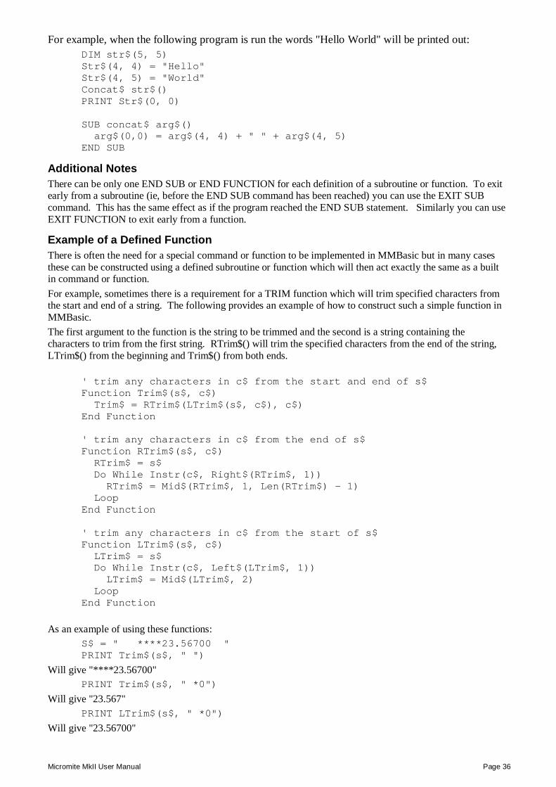
Micromite MkII User Manual Page 36
For example, when the following program is run the words "Hello World" will be printed out: DIM str$(5, 5) Str$(4, 4) = "Hello" Str$(4, 5) = "World" Concat$ str$() PRINT Str$(0, 0) SUB concat$ arg$() arg$(0,0) = arg$(4, 4) + " " + arg$(4, 5) END SUB
Additional Notes There can be only one END SUB or END FUNCTION for each definition of a subroutine or function. To exit early from a subroutine (ie, before the END SUB command has been reached) you can use the EXIT SUB command. This has the same effect as if the program reached the END SUB statement. Similarly you can use EXIT FUNCTION to exit early from a function.
Example of a Defined Function There is often the need for a special command or function to be implemented in MMBasic but in many cases these can be constructed using a defined subroutine or function which will then act exactly the same as a built in command or function. For example, sometimes there is a requirement for a TRIM function which will trim specified characters from the start and end of a string. The following provides an example of how to construct such a simple function in MMBasic. The first argument to the function is the string to be trimmed and the second is a string containing the characters to trim from the first string. RTrim$() will trim the specified characters from the end of the string, LTrim$() from the beginning and Trim$() from both ends.
' trim any characters in c$ from the start and end of s$ Function Trim$(s$, c$) Trim$ = RTrim$(LTrim$(s$, c$), c$) End Function ' trim any characters in c$ from the end of s$ Function RTrim$(s$, c$) RTrim$ = s$ Do While Instr(c$, Right$(RTrim$, 1)) RTrim$ = Mid$(RTrim$, 1, Len(RTrim$) - 1) Loop End Function ' trim any characters in c$ from the start of s$ Function LTrim$(s$, c$) LTrim$ = s$ Do While Instr(c$, Left$(LTrim$, 1)) LTrim$ = Mid$(LTrim$, 2) Loop End Function
As an example of using these functions: S$ = " ****23.56700 " PRINT Trim$(s$, " ")
Will give "****23.56700" PRINT Trim$(s$, " *0")
Will give "23.567" PRINT LTrim$(s$, " *0")
Will give "23.56700"
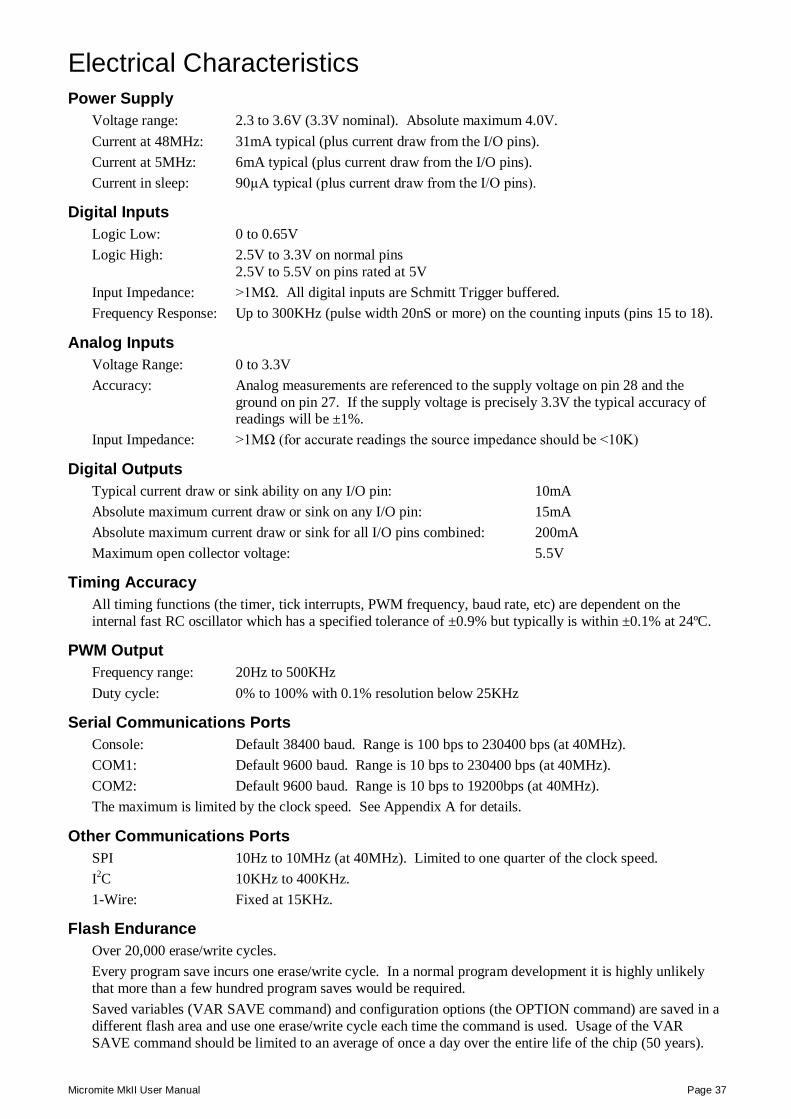
Micromite MkII User Manual Page 37
Electrical Characteristics Power Supply
Voltage range: 2.3 to 3.6V (3.3V nominal). Absolute maximum 4.0V. Current at 48MHz: 31mA typical (plus current draw from the I/O pins). Current at 5MHz: 6mA typical (plus current draw from the I/O pins). Current in sleep: 90µA typical (plus current draw from the I/O pins).
Digital Inputs Logic Low: 0 to 0.65V Logic High: 2.5V to 3.3V on normal pins
2.5V to 5.5V on pins rated at 5V Input Impedance: >1MΩ. All digital inputs are Schmitt Trigger buffered. Frequency Response: Up to 300KHz (pulse width 20nS or more) on the counting inputs (pins 15 to 18).
Analog Inputs Voltage Range: 0 to 3.3V Accuracy: Analog measurements are referenced to the supply voltage on pin 28 and the
ground on pin 27. If the supply voltage is precisely 3.3V the typical accuracy of readings will be ±1%.
Input Impedance: >1MΩ (for accurate readings the source impedance should be <10K)
Digital Outputs Typical current draw or sink ability on any I/O pin: 10mA Absolute maximum current draw or sink on any I/O pin: 15mA Absolute maximum current draw or sink for all I/O pins combined: 200mA Maximum open collector voltage: 5.5V
Timing Accuracy All timing functions (the timer, tick interrupts, PWM frequency, baud rate, etc) are dependent on the internal fast RC oscillator which has a specified tolerance of ±0.9% but typically is within ±0.1% at 24ºC.
PWM Output Frequency range: 20Hz to 500KHz Duty cycle: 0% to 100% with 0.1% resolution below 25KHz
Serial Communications Ports Console: Default 38400 baud. Range is 100 bps to 230400 bps (at 40MHz). COM1: Default 9600 baud. Range is 10 bps to 230400 bps (at 40MHz). COM2: Default 9600 baud. Range is 10 bps to 19200bps (at 40MHz). The maximum is limited by the clock speed. See Appendix A for details.
Other Communications Ports SPI 10Hz to 10MHz (at 40MHz). Limited to one quarter of the clock speed. I2C 10KHz to 400KHz. 1-Wire: Fixed at 15KHz.
Flash Endurance Over 20,000 erase/write cycles. Every program save incurs one erase/write cycle. In a normal program development it is highly unlikely that more than a few hundred program saves would be required. Saved variables (VAR SAVE command) and configuration options (the OPTION command) are saved in a different flash area and use one erase/write cycle each time the command is used. Usage of the VAR SAVE command should be limited to an average of once a day over the entire life of the chip (50 years).
Micromite MkII User Manual Page 38
MMBasic Characteristics Naming Conventions Command names, function names, labels, variable names, file names, etc are not case sensitive, so that "Run" and "RUN" are equivalent and "dOO" and "Doo" refer to the same variable. There are three types of variables:
4. Floating point. These can store a number with a decimal point and fraction (eg, 45.386) and also very large numbers. However, they will loose accuracy when more than seven significant digits are stored or manipulated. These are specified by adding the suffix '!' to a variable's name and are the default when a variable is created without a suffix (eg, i, nbr, etc).
5. 64-bit integer. These can store numbers with up to 19 decimal digits without loosing accuracy but they cannot store fractions (ie, the part following the decimal point). These are specified by adding the suffix '%' to a variable's name. For example, i%, nbr%, etc.
6. Strings. These will store a string of characters (eg, "Tom"). String variable names are terminated with a '$' symbol (eg, name$, s$, etc). Strings can be up to 255 characters long.
Variable names and labels can start with an alphabetic character or underscore and can contain any alphabetic or numeric character, the period (.) and the underscore (_). They may be up to 32 characters long. A variable name or a label must not be the same as a command or a function or one of the following keywords: THEN, ELSE, TO, STEP, FOR, WHILE, UNTIL, MOD, NOT, AND, OR, XOR, AS. Eg, step = 5 is illegal.
Constants Numeric constants may begin with a numeric digit (0-9) for a decimal constant, &H for a hexadecimal constant, &O for an octal constant or &B for a binary constant. For example &B1000 is the same as the decimal constant 8. Constants that start with &H, &O or &B are always treated as 64-bit integer constants. Decimal constants may be preceded with a minus (-) or plus (+) and may be terminated with 'E' followed by an exponent number to denote exponential notation. For example 1.6E+4 is the same as 16000. If the decimal constant contains a decimal point or an exponent, it will be treated as a floating point constant; otherwise it will be treated as a 64-bit integer constant. String constants are surrounded by double quote marks ("). Eg, "Hello World".
Operators and Precedence The following operators, in order of precedence, are recognised. Operators that are on the same level (for example + and -) are processed with a left to right precedence as they occur on the program line.
Arithmetic operators:
^ Exponentiation
* / \ MOD Multiplication, division, integer division and modulus (remainder)
+ - Addition and subtraction
Shift operators:
x << y x >> y These operate in a special way. << means that the value returned will be the value of x shifted by y bits to the left while >> means the same only right shifted. They are integer functions and any bits shifted off are discarded and any bits introduced are set to zero.
Logical operators:
NOT logical inverse of the value on the right
<> < > <= =< >= =>
Inequality, less than, greater than, less than or equal to, less than or equal to (alternative version), greater than or equal to, greater than or equal to (alternative version)
= equality
AND OR XOR Conjunction, disjunction, exclusive or
Micromite MkII User Manual Page 39
The operators AND, OR and XOR are integer bitwise operators. For example PRINT 3 AND 6 will output 2. The other logical operations result in the integer 0 (zero) for false and 1 for true. For example the statement PRINT 4 >= 5 will print the number zero on the output and the expression A = 3 > 2 will store +1 in A. The NOT operator is highest in precedence so it will bind tightly to the next value. For normal use the expression to be negated should be placed in brackets. For example, IF NOT (A = 3 OR A = 8) THEN …
String operators:
+ Join two strings
<> < > <= =< >= =>
Inequality, less than, greater than, less than or equal to, less than or equal to (alternative version), greater than or equal to, greater than or equal to (alternative version)
= Equality
Implementation Characteristics Maximum program size (as plain text) is 53K. Note that MMBasic tokenises the program when it is stored in flash so the final size in flash might vary from the plain text size. Maximum length of a command line is 255 characters. Maximum length of a variable name or a label is 32 characters. Maximum number of dimensions to an array is 8. Maximum number of arguments to commands that accept a variable number of arguments is 50. Maximum number of nested FOR…NEXT loops is 10. Maximum number of nested DO…LOOP commands is 10. Maximum number of nested GOSUBs, subroutines and functions (combined) is 50. Maximum number of nested multiline IF…ELSE…ENDIF commands is 10. Maximum number of user defined subroutines and functions (combined): 100 Numbers are stored and manipulated as single precision floating point numbers or 64-bit signed integers. The maximum floating point number allowable is 3.40282347e+38 and the minimum is 1.17549435e-38. The range of 64-bit integers (whole numbers) that can be manipulated is ± 9223372036854775807. Maximum string length is 255 characters. Maximum line number is 65000. Maximum number of background pulses launched by the PULSE command is 5.
Compatibility MMBasic implements a large subset of Microsoft’s GW-BASIC. There are numerous small differences due to physical and practical considerations but most MMBasic commands and functions are essentially the same. An online manual for GW-BASIC is available at http://www.antonis.de/qbebooks/gwbasman/index.html and this provides a more detailed description of the commands and functions. MMBasic also implements a number of modern programming structures documented in the ANSI Standard for Full BASIC (X3.113-1987) or ISO/IEC 10279:1991. These include SUB/END SUB, the DO WHILE … LOOP, the SELECT…CASE statements and structured IF .. THEN … ELSE … ENDIF statements.
License MMBasic is Copyright 2011-2015 by Geoff Graham - http://mmbasic.com. The compiled object code (the .hex file) is free software: you can use or redistribute it as you please. This program is distributed in the hope that it will be useful, but WITHOUT ANY WARRANTY; without even the implied warranty of MERCHANTABILITY or FITNESS FOR A PARTICULAR PURPOSE. The source code is available via subscription (free of charge) to individuals for personal use or under a negotiated license for commercial use. In both cases go to http://mmbasic.com for details. This manual is distributed under a Creative Commons Attribution-NonCommercial-ShareAlike 3.0 Australia license (CC BY-NC-SA 3.0)
Micromite MkII User Manual Page 40
Predefined Read Only Variables Detailed Listing These variables are set by MMBasic and cannot be changed by the running program.
MM.VER The version number of the firmware in the form aa.bbcc where aa is the major version number, bb is the minor version number and cc is the revision number (normally zero but A = 01, B = 02, etc).
MM.DEVICE$ A string representing the device or platform that MMBasic is running on. Currently this variable will contain one of the following:
"Maximite" on the standard Maximite and compatibles. "Colour Maximite" on the Colour Maximite and UBW32. "DuinoMite" when running on one of the DuinoMite family. "DOS" when running on Windows in a DOS box. "Generic PIC32" for the generic version of MMBasic on a PIC32. "Micromite" on the PIC32MX150/250 "Micromite MkII" on the PIC32MX170/270
MM.WATCHDOG True if MMBasic was restarted as the result of a Watchdog timeout (see the WATCHDOG command). False if MMBasic started up normally.
MM.I2C Following an I2C write or read command this variable will be set to indicate the result of the operation as follows:
0 = The command completed without error. 1 = Received a NACK response 2 = Command timed out
MM.ONEWIRE Following a 1-Wire reset function this variable will be set to indicate the result of the operation as follows:
0 = Device not found. 1 = Device found
Micromite MkII User Manual Page 41
Commands Detailed Listing Note that the commands related to the I2C, 1-Wire, and SPI communications functions are not listed here but are described in the appendices at the end of this document. Square brackets indicate that the parameter or characters are optional.
‘ (single quotation mark) Starts a comment and any text following it will be ignored. Comments can be placed anywhere on a line.
? (question mark) Shortcut for the PRINT command.
AUTOSAVE Enter automatic program entry mode. This command will take lines of text from the console serial input and save them to memory. This mode is terminated by entering Control-Z which will then cause the received data to be saved into program memory overwriting the previous program. At any time this command can be aborted by Control-C which will leave program memory untouched. This is one way of transferring a BASIC program into the Micromite. The program to be transferred can be pasted into a terminal emulator and this command will capture the text stream and store it into program memory. It can also be used for entering a small program directly at the console input.
CFUNCTION name hex [[ hex[…] hex [[ hex[…] END CFUNCTION
Defines the binary code for a program module (a "C Function") written in C or MIPS assembler. The module will appear in MMBasic as the function 'name' and can be used in the same manner as a built-in function. This command specifies the hex codes for the module. These are automatically programmed into MMBasic when the program is saved. Each 'hex' must be exactly eight hex digits representing the bits in a 32-bit word.
Each 'hex' word must be separated by one or more spaces and multiple lines of 'hex' words can be used. The command must be terminated by a matching END CFUNCTION.
The first 'hex' word must be the offset (in 32-bit words) to the entry point of the CFunction (usually the function main()).
Multiple CFUNCTION commands can be used with each defining a different module with a different 'name'.
During execution MMBasic will skip over any CFUNCTION commands so they can be placed anywhere in the program.
Any errors in the data format will be reported when the program is saved. The function 'name' created by the CFUNCTION command can be used as a normal function within MMBasic with a few caveats:
The function will always return an integer. Up to ten values can be specified as parameters ('arg1', 'arg2', etc) and
they will be passed to the C function as pointers to the memory space allocated to each value (ie, the result of the expression).
If a variable or array is specified as an argument the C function will receive a pointer to the memory allocated to the variable or array and the C function can change this memory to return a value to the caller.
In the case of arrays, they should be passed with empty brackets. eg, arg(). In the C function the argument will be supplied as a pointer to the first element of the array.
For more details and a tutorial on using this feature refer to: http://geoffg.net/Downloads/Micromite/cfunctions.pdf WARNING: No validation is made and faulty code in the module can cause a CPU exception which will force the Micromite to restart without warning.
Micromite MkII User Manual Page 42
CLEAR Delete all variables and recover the memory used by them. See ERASE for deleting specific array variables.
CLOSE [#]nbr [,[#]nbr] … Close the serial communications port(s) previously opened with the file number ‘nbr’. The # is optional. Also see the OPEN command.
CONST id = expression [, id = expression] … etc
Create a constant identifier which cannot be changed once created. 'id' is the identifier which follows the same rules as for variables. The identifier can have a type suffix (!, %, or $) but it is not required. If it is specified it must match the type of 'expression'. 'expression' is the value of the identifier and it can be a normal expression (including user defined functions) which will be evaluated when the constant is created. A constant defined outside a sub or function is global and can be seen throughout the program. A constant defined inside a sub or function is local to that routine and will hide a global constant with the same name.
CONTINUE Resume running a program that has been stopped by an END statement, an error, or CTRL-C. The program will restart with the next statement following the previous stopping point.
CPU speed Set the clock speed of the processor. 'speed' is set in MHz and can be either 48, 40, 30, 20, 10, or 5. Current drawn by the chip is proportional to the clock speed, so by halving the clock speed the current drain is roughly halved. The default speed of the CPU when power is applied is 40MHz. When the speed is changed all timing functions in MMBasic will be automatically corrected to keep the correct time and the console baud rate will be unchanged. The serial communications ports COM1 and COM2 can remain open during the speed change and their speed will be adjusted accordingly. Note that there may be a glitch while changing speed and some characters may be lost or corrupted. The speed of any SPI, I2C and PWM functions open at the time will change with the clock speed. For this reason they should be closed before this command is used and reopened after.
CPU SLEEP seconds or CPU SLEEP
Put the CPU to sleep. In this mode the running program will be halted and the current drain reduced considerably. In the first form (CPU SLEEP seconds) the command will put the CPU to sleep for the specified number of 'seconds' (maximum of 10 days). The current drain in this mode is about 90µA. This command will update the TIMER function when it comes out of sleep but note that the sleep time is not very accurate, it can vary by up to ±20%. In the second form the WAKEUP pin (pin16 on 28-pin devices and pin 43 on 44-pin devices) will be automatically configured as a digital input and any change in its state (ie, from high to low or low to high) will wakeup the CPU. The current drain in this mode is about 80µA. The IR command shares the WAKEUP pin and if it is running the CPU will be awakened by the remote key press and MMBasic will immediately decode the signal and execute the IR interrupt. Notes: The CPU will go to sleep in the middle of the SLEEP command and
when awakened continue with normal program execution. All communications (serial, SPI, I2C and 1-Wire) and PWM will be
frozen during sleep. When the CPU comes out of sleep they will resume normal processing. It is recommended that they be closed before entering sleep as they will add to the current drawn by the chip in sleep.
The time required to "wake up" ranges from 0.4mS at a CPU speed of
Micromite MkII User Manual Page 43
40MHz to 1mS at 5MHz. The I/O pins will remain active and any that are set as outputs will
continue to source or draw current depending on their state and attached components. This should be considered when trying to reduce the current drain during sleep.
All timing functions will freeze during the sleep, this includes the real time clock and background pulse commands.
CTRL-C on the console will not bring the chip out of sleep.
CPU RESTART Will force a restart of the processor. This will clear all variables and reset everything (eg, timers, COM ports, I2C, etc) similar to a power up situation but without the power up banner. If OPTION AUTORUN has been set the program in memory will restart.
DATA constant[,constant]... Stores numerical and string constants to be accessed by READ. In general string constants should be surrounded by double quotes ("). An exception is when the string consists of just alphanumeric characters that do not represent MMBasic keywords (such as THEN, WHILE, etc). In that case quotes are not needed. Numerical constants can also be expressions such as 5 * 60.
DATE$ = "DD-MM-YY" or DATE$ = "DD/MM/YY"
Set the date of the internal clock/calendar. DD, MM and YY are numbers, for example: DATE$ = "28-7-2014" The date is set to "1-1-2000" on power up.
DHT22 pin, tvar, hvar
Returns the temperature and humidity using the DHT22 sensor. Alternative versions of the DHT22 are the AM2303 or the RHT03 (all are compatible). 'pin' is the I/O pin connected to the sensor. Any I/O pin may be used. 'tvar' is the variable that will hold the measured temperature and 'hvar' is the same for humidity. Both must be present and both must be floating point variables. For example: DHT22 2, TEMP!, HUMIDITY! Temperature is measured in ºC and the humidity is percent relative humidity. Both will be measured with a resolution of 0.1. If an error occurs (sensor not connected or corrupt signal) both values will be 1000.0. The CPU speed must be 10MHz or higher and the measurement will take 6mS to complete. Normally the signal pin of the DHT22 should be pulled up by a 1K to 10K resistor (4.7K recommended) to the supply voltage. The Micromite will also enable an internal high value pullup resistor so when the cable length is short (under 30cm) the external pullup resistor may be omitted.
DIM [type] decl [,decl]... where 'decl' is: var [length] [type] [init] 'var' is a variable name with optional dimensions 'length' is used to set the maximum size of the string to 'n' as in LENGTH n 'type' is one of AS FLOAT or AS INTEGER or AS STRING 'init' is the value to initialise the variable and consists of: = <expression> For a simple variable one expression is used, for an array a list of comma separated
Declares one or more variables (ie, makes the variable name and its characteristics known to the interpreter). When OPTION EXPLICIT is used (as recommended) the DIM or LOCAL commands are the only way that a variable can be created. If this option is not used then using the DIM command is optional and if not used the variable will be created automatically when first referenced. The type of the variable (ie, string, float or integer) can be specified in one of three ways: By using a type suffix (ie, !, % or $ for float, integer or string). For example:
DIM nbr%, amount!, name$
By using one of the keywords FLOAT, INTEGER or STRING immediately after the command DIM and before the variable(s) are listed. The specified type then applies to all variables listed (ie, it does not have to be repeated). For example:
DIM AS STRING first_name, last_name, city
Micromite MkII User Manual Page 44
expressions surrounded by brackets is used. Examples: DIM nbr(50) DIM INTEGER nbr(50) DIM name AS STRING DIM a, b$, nbr(100), str$(20) DIM a(5,5,5), b(1000) DIM str$(200) LENGTH 20 DIM STRING str(200) LENGTH 20 DIM a = 1234, b = 345 DIM STRING str = "text" DIM x%(3) = (11, 22, 33, 44)
By using the Microsoft convention of using the keyword "AS" and the type keyword (ie, FLOAT, INTEGER or STRING) after each variable. If you use this method the type must be specified for each variable and can be changed from variable to variable. For example:
DIM amount AS FLOAT, name AS STRING
Floating point or integer variables will be set to zero when created and strings will be set to an empty string (ie, ""). You can initialise the value of the variable with something different by using an equals symbol (=) and an expression following the variable definition. For example:
DIM AS STRING city = "Perth", house = "Brick"
The initialising value can be an expression (including other variables) and will be evaluated when the DIM command is executed. See the section "Defining and Using Variables" for more examples of the syntax. As well as declaring simple variables the DIM command will also declare arrayed variables (ie, an indexed variable with a number of dimensions). Following the variable's name the dimensions are specified by a list of numbers separated by commas and enclosed in brackets. For example:
DIM array(10, 20)
Each number specifies the number of elements in each dimension. Normally the numbering of each dimension starts at 0 but the OPTION BASE command can be used to change this to 1. The above example specifies a two dimensional array with 11 elements (0 to 10) in the first dimension and 21 (0 to 20) in the second dimension. The total number of elements is 231 and because each floating point number requires 4 bytes a total of 924 bytes of memory will be allocated (integers are different and require 8 bytes per element). Strings will default to allocating 255 bytes (eg, characters) of memory for each element and this can quickly use up memory. In that case the LENGTH keyword can be used to specify the amount of memory to be allocated to each element and therefore the maximum length of the string that can be stored. This allocation ('n') can be from 1 to 255 characters. For example: DIM str$(5, 10) will declare a string array with 66 elements consuming 16,896 bytes of memory while:
DIM AS STRING str (5, 10) LENGTH 20
Will only consume 1,386 bytes of memory. Note that the amount of memory allocated for each element is n + 1 as the extra byte is used to track the actual length of the string stored in each element. If a string longer than 'n' is assigned to an element of the array an error will be produced. Other than this string arrays created with the LENGTH keyword act exactly the same as other string arrays. Note that the LENGTH keyword can also be used when defining non array string variables. In the above example you can also use the Microsoft syntax of specifying the type after the length specifier. For example:
DIM str (5, 10) LENGTH 20 AS STRING
Arrays can also be initialised when they are declared by adding an equals symbol (=) followed by a bracketed list of values at the end of the declaration. For example:
DIM INTEGER nbr(4) = (22, 44, 55, 66, 88)
or DIM str$(3) = ("foo", "boo", "doo", "zoo")
Note that the number of initialising values must match the number of elements in the array including the base value set by OPTION BASE. If a multi dimensioned array is initialised then the first dimension will be
Micromite MkII User Manual Page 45
initialised first followed by the second, etc.
DO <statements> LOOP
This structure will loop forever; the EXIT command can be used to terminate the loop or control must be explicitly transferred outside of the loop by commands like GOTO or RETURN (if in a subroutine).
DO WHILE expression <statements> LOOP
Loops while "expression" is true (this is equivalent to the older WHILE-WEND loop, also implemented in MMBasic). If, at the start, the expression is false the statements in the loop will not be executed, even once.
DO <statements> LOOP UNTIL expression
Loops until the expression following UNTIL is true. Because the test is made at the end of the loop the statements inside the loop will be executed at least once, even if the expression is false.
DS18B20 START pin [, precision]
This command can be used to start a conversion running on a DS18B20 temperature sensor connected to 'pin'. Note that only a single space is allowed between DS18B20 and START. Normally the DS18B20() function alone is sufficient to make a temperature measurement so usage of this command is optional and can be ignored. This command will start the measurement on the temperature sensor. The program can then attend to other duties while the measurement is running and later use the DS18B20() function to get the reading. If the DS18B20() function is used before the conversion time has completed the function will wait for the remaining conversion time before returning the value. 'precision' is the resolution of the measurement and is optional. It is a number between 0 and 3 meaning:
0 = 0.5ºC resolution, 100mS conversion time. 1 = 0.25ºC resolution, 200mS conversion time (this is the default). 2 = 0.125ºC resolution, 400mS conversion time. 3 = 0.0625ºC resolution, 800mS conversion time.
EDIT Invoke the full screen editor. All the editing keys work with a VT100 terminal emulator so editing can also be accomplished over the console serial link. The editor has been tested with Tera Term and PuTTY running on a Windows PC. On entry the cursor will be automatically positioned at the last line edited or, if there was an error when running the program, the line that caused the error. The editing keys are:
Left/Right arrows Moves the cursor within the line. Up/Down arrows Moves the cursor up or down a line. Page Up/Down Move up or down a page of the program. Home/End Moves the cursor to the start or end of the line. A
second Home/End will move to the start or end of the program.
Delete Delete the character over the cursor. This can be the line separator character and thus join two lines.
Backspace Delete the character before the cursor. Insert Will switch between insert and overtype mode. Escape Key Will close the editor without saving (confirms first). F1 Save the edited text and exit. F2 Save, exit and run the program. F3 Invoke the search function. SHIFT F3 Repeat the search using the text entered with F3. F4 Mark text for cut or copy (see below). F5 Paste text previously cut or copied.
When in the mark text mode (entered with F4) the editor will allow you to
Micromite MkII User Manual Page 46
use the arrow keys to highlight text which can be deleted, cut to the clipboard or simply copied to the clipboard. The status line will change to indicate the new functions of the function keys. The editor will work with lines wider than the screen but characters beyond the screen edge will not be visible. You can split such a line by inserting a new line character and the two lines can be later rejoined by deleting the inserted new line character. Note that the program is edited in RAM which limits its size to 53K.
ELSE Introduces a default condition in a multiline IF statement. See the multiline IF statement for more details.
ELSEIF expression THEN or ELSE IF expression THEN
Introduces a secondary condition in a multiline IF statement. See the multiline IF statement for more details.
ENDIF or END IF
Terminates a multiline IF statement. See the multiline IF statement for more details.
END End the running program and return to the command prompt.
END FUNCTION Marks the end of a user defined function. See the FUNCTION command. Each function must have one and only one matching END FUNCTION statement. Use EXIT FUNCTION if you need to return from a function from within its body.
END SUB Marks the end of a user defined subroutine. See the SUB command. Each sub must have one and only one matching END SUB statement. Use EXIT SUB if you need to return from a subroutine from within its body.
ERASE variable [,variable]... Deletes arrayed variables and frees up the memory. Use CLEAR to delete all variables including all arrayed variables.
ERROR [error_msg$] Forces an error and terminates the program. This is normally used in debugging or to trap events that should not occur.
EXIT DO EXIT FOR EXIT FUNCTION EXIT SUB
EXIT DO provides an early exit from a DO...LOOP EXIT FOR provides an early exit from a FOR...NEXT loop. EXIT FUNCTION provides an early exit from a defined function. EXIT SUB provides an early exit from a defined subroutine. The old standard of EXIT on its own (exit a do loop) is also supported.
FOR counter = start TO finish [STEP increment]
Initiates a FOR-NEXT loop with the 'counter' initially set to 'start' and incrementing in 'increment' steps (default is 1) until 'counter' equals 'finish'. The ‘increment’ must be an integer, but may be negative in which case the loop will count downwards. See also the NEXT command.
FUNCTION xxx (arg1 [,arg2, …]) [AS <type> <statements> <statements> xxx = <return value> END FUNCTION
Defines a callable function. This is the same as adding a new function to MMBasic while it is running your program. 'xxx' is the function name and it must meet the specifications for naming a variable. The type of the function can be specified by using a type suffix (ie, xxx$) or by specifying the type using AS <type> at the end of the functions definition. For example:
FUNCTION xxx (arg1, arg2) AS STRING
'arg1', 'arg2', etc are the arguments or parameters to the function. An array is specified by using empty brackets. ie, arg3(). The type of the argument can be specified by using a type suffix (ie, arg1$) or by specifying the type using AS <type> (ie, arg1 AS STRING).
Micromite MkII User Manual Page 47
The argument can also be another defined function or the same function if recursion is to be used (the recursion stack is limited to 50 nested calls). To set the return value of the function you assign the value to the function's name. For example:
FUNCTION SQUARE(a) SQUARE = a * a END FUNCTION
Every definition must have one END FUNCTION statement. When this is reached the function will return its value to the expression from which it was called. The command EXIT FUNCTION can be used for an early exit. You use the function by using its name and arguments in a program just as you would a normal MMBasic function. For example:
PRINT SQUARE(56.8)
When the function is called each argument in the caller is matched to the argument in the function definition. These arguments are available only inside the function. Functions can be called with a variable number of arguments. Any omitted arguments in the function's list will be set to zero or a null string. Arguments in the caller's list that are a variable (ie, not an expression or constant) will be passed by reference to the function. This means that any changes to the corresponding argument in the function will also be copied to the caller's variable. Arrays are passed by specifying the array name with empty brackets (eg, arg()) and are always passed by reference. You must not jump into or out of a function using commands like GOTO, GOSUB, etc. Doing so will have undefined side effects including the possibility of ruining your day.
GOSUB target Initiates a subroutine call to the target, which can be a line number or a label. The subroutine must end with RETURN.
GOTO target Branches program execution to the target, which can be a line number or a label.
IF expr THEN statement or IF expr THEN stmt ELSE stmt
Evaluates the expression ‘expr' and performs the THEN statement if it is true or skips to the next line if false. The optional ELSE statement is the reverse of the THEN test. This type of IF statement is all on one line. The ‘THEN statement’ construct can be also replaced with: GOTO linenumber | label’.
IF expression THEN <statements> [ELSE <statements>] [ELSEIF expression THEN <statements>] ENDIF
Multiline IF statement with optional ELSE and ELSEIF cases and ending with ENDIF. Each component is on a separate line. Evaluates 'expression' and performs the statement(s) following THEN if the expression is true or optionally the statement(s) following the ELSE statement if false. The ELSEIF statement (if present) is executed if the previous condition is false and it starts a new IF chain with further ELSE and/or ELSEIF statements as required. One ENDIF is used to terminate the multiline IF.
Micromite MkII User Manual Page 48
INPUT ["prompt string$";] list of variables
Allows input from the console to a list of variables. The input command will prompt with a question mark (?). The input must contain commas to separate each data item if there is more than one variable. For example, if the command is: INPUT a, b, c And the following is typed on the keyboard: 23, 87, 66 Then a = 23 and b = 87 and c = 66 If the "prompt string$" is specified it will be printed before the question mark. If the prompt string is terminated with a comma (,) rather than the semicolon (;) the question mark will be suppressed.
INPUT #nbr, list of variables
Same as above except that the input is read from a serial port previously opened for INPUT as ‘nbr’. See the OPEN command.
IR dev, key , interrupt or IR CLOSE
Decodes NEC or Sony infrared remote control signals. An IR Receiver Module is used to sense the IR light and demodulate the signal. It should be connected to pin 16 (28-pin devices) or pin 43 (44-pin devices). This command will automatically set that pin to an input. The IR signal decode is done in the background and the program will continue after this command without interruption. 'dev' and 'key' should be numeric variables and their values will be updated whenever a new signal is received ('dev' is the device code transmitted by the remote and 'key' is the key pressed). 'interrupt' is the line number or label of the interrupt routine that will be called when a new key press is received or when the existing key is held down for auto repeat. In the interrupt routine the program can examine the variables 'dev' and 'key' and take appropriate action. The IRETURN command is used to return from the interrupt. A subroutine can also be specified for the interrupt target and in that case return is via EXIT SUB or END SUB. The IR CLOSE command will terminate the IR decoder and return the I/O pin to a not configured state. See the section "Special Hardware Devices" for more details.
IR SEND pin, dev, key Generate a 12-bit Sony Remote Control protocol infrared signal. 'pin' is the I/O pin to use. This can be any I/O pin which will be automati-cally configured as an output and should be connected to an infrared LED. Idle is low with high levels indicating when the LED should be turned on. 'dev' is the device being controlled and is a number from 0 to 31, 'key' is the simulated key press and is a number from 0 to 127. The IR signal is modulated at about 38KHz and sending the signal takes about 25mS. The CPU speed must be 10MHz or above.
IRETURN Returns from an interrupt that used a line number or label. The next statement to be executed will be the one that was about to be executed when the interrupt was detected. Note that IRETURN must not be used where the interrupt routine is a user defined subroutine. In that case END SUB or EXIT SUB should be used.
KEYPAD var, int, r1, r2, r3, r4, c1, c2, c3 [, c4] or KEYPAD CLOSE
Monitor and decode key presses on a 4x3 or 4x4 keypad. Monitoring of the keypad is done in the background and the program will continue after this command without interruption. 'var' should be a numeric variable and its value will be updated whenever a key press is detected. 'int' is the line number or label of the interrupt routine that will be called when a new key press is received. In the interrupt routine the program can examine the variable 'var' and take appropriate action. The IRETURN command is used to return from the interrupt. A subroutine can also be specified for the interrupt target and in that case return is via EXIT SUB or END SUB.
Micromite MkII User Manual Page 49
r1, r2, r3 and r4 are pin numbers used for the four row connections to the keypad and c1, c2, c3 and c4 are the column connections. c4 is optional and is only used with 4x4 keypads. This command will automatically configure these pins as required. On a key press the value assigned to 'var' is the number of a numeric key (eg, '6' will return 6) or 10 for the * key and 11 for the # key. On 4x4 keypads the number 20 will be returned for A, 21 for B, 22 for C and 23 for D. The KEYPAD CLOSE command will terminate the keypad function and return the I/O pin to a not configured state. See the section "Special Hardware Devices" for more details.
LET variable = expression Assigns the value of 'expression' to the variable. LET is automatically assumed if a statement does not start with a command.
LCD INIT d4, d5, d6, d7, rs, en or LCD line, pos, text$ or LCD CLEAR or LCD CLOSE
Display text on an LCD character display module. This command will work with most 1-line, 2-line or 4-line LCD modules that use the KS0066, HD44780 or SPLC780 controller (however this is not guaranteed). The LCD INIT command is used to initialise the LCD module for use. 'd4' to 'd7' are the I/O pins that connect to inputs D4 to D7 on the LCD module (inputs D0 to D3 should be connected to ground). 'rs' is the pin connected to the register select input on the module (sometimes called CMD). 'en' is the pin connected to the enable or chip select input on the module. The R/W input on the module should always be grounded. The above I/O pins are automatically set to outputs by this command. When the module has been initialised data can be written to it using the LCD command. 'line' is the line on the display (1 to 4) and 'pos' is the character location on the line (the first location is 1). 'text$' is a string containing the text to write to the LCD display. 'pos' can also be C8, C16, C20 or C40 in which case the line will be cleared and the text centred on a 8 or 16, 20 or 40 line display. For example: LCD 1, C16, "Hello"
LCD CLEAR will erase all data displayed on the LCD and LCD CLOSE will terminate the LCD function and return all I/O pins to the not configured state. See the section "Special Hardware Devices" for more details.
LCD CMD d1 [, d2 [, etc]] or LCD DATA d1 [, d2 [, etc]]
These commands will send one or more bytes to an LCD display as either a command (LCD CMD) or as data (LCD DATA). Each byte is a number between 0 and 255 and must be separated by commas. The LCD must have been previously initialised using the LCD INIT command (see above). These commands can be used to drive a non standard LCD in "raw mode" or they can be used to enable specialised features such as scrolling, cursors and custom character sets. You will need to refer to the data sheet for your LCD to find the necessary command and data values.
LINE INPUT [prompt$,] string-variable$
Reads entire line from the serial console input into ‘string-variable$’. If specified the ‘prompt$’ will be printed first. Unlike INPUT, LINE INPUT will read a whole line, not stopping for comma delimited data items. A question mark is not printed unless it is part of ‘prompt$’.
LINE INPUT #nbr, string-variable$
Same as above except that the input is read from a serial communications port previously opened for INPUT as ‘nbr’. See the OPEN command.
LIST or LIST ALL
List a program on the serial console. LIST on its own will list the program with a pause at every screen full. LIST ALL will list the program without pauses. This is useful if you wish to transfer the program in the Micromite to a terminal emulator on a PC that has the ability to capture its input stream to a file.
Micromite MkII User Manual Page 50
LOCAL variable [, variables] See DIM for the full syntax.
Defines a list of variable names as local to the subroutine or function. This command works exactly the same as DIM except that the variables will only be visible within the subroutine or function. Note: LOCAL can only be used in a subroutine or function. It uses exactly the same syntax as DIM.
LOOP [UNTIL expression] Terminates a program loop: see DO.
MEMORY List the amount of memory currently in use. For example: Flash: 21K (35%) Program (805 lines) 1K ( 1%) 2 CFunctions 1K ( 1%) 4 Saved Variables 37K (63%) Free
RAM: 9K (16%) 5 Variables 18K (32%) General 26K (52%) Free
Notes: General memory is used by serial I/O buffers, etc. Program memory is cleared by the NEW command. Variables and the general memory spaces are cleared by many
commands (eg, NEW, RUN, etc) as well as the specific commands CLEAR and ERASE.
Memory usage is rounded to the nearest 1K byte. When a program is loaded it is first buffered in RAM which limits the
maximum program size to 53K. MMBasic tokenises the program when it is stored in flash so the final size in flash might vary from this.
NEW Deletes the program in flash and clears all variables.
NEXT [counter-variable] [, counter-variable], etc
NEXT comes at the end of a FOR-NEXT loop; see FOR. The ‘counter-variable’ specifies exactly which loop is being operated on. If no ‘counter-variable’ is specified the NEXT will default to the innermost loop. It is also possible to specify multiple counter-variables as in: NEXT x, y, z
ON nbr GOTO | GOSUB target[,target, target,...]
ON either branches (GOTO) or calls a subroutine (GOSUB) based on the rounded value of 'nbr'; if it is 1, the first target is called, if 2, the second target is called, etc. Target can be a line number or a label.
ON KEY target Setup an interrupt which will call 'target' line number, label or user defined subroutine whenever there is one or more characters waiting in the serial console input buffer. Return from an interrupt is via the IRETURN statement except where a user defined subroutine is used (in that case END SUB or EXIT SUB is used). Note that subroutine parameters cannot be used. Note that all characters waiting in the input buffer should be read in the interrupt routine otherwise another interrupt will be automatically generated as soon as the program returns from the interrupt. To disable this interrupt, use numeric zero for the target, ie: ON KEY 0
OPEN comspec$ AS [#]fnbr Will open a serial communications port for reading and writing. Two ports are available (COM1: and COM2:) and both can be open simultaneously. For a full description with examples see Appendix A. Using ‘fnbr’ the port can be written to and read from using any command or function that uses a file number.
Micromite MkII User Manual Page 51
OPTION AUTORUN OFF | ON
Instruct MMBasic to automatically run the program stored in flash when it starts up or is restarted by the WATCHDOG command. This is turned off by the NEW command but other commands that might change program memory (EDIT, etc) do not change this setting.
OPTION BASE 0 | 1
Set the lowest value for array subscripts to either 0 or 1. This must be used before any arrays are declared and is reset to the default of 0 on power up.
OPTION BAUDRATE nbr
Set the baud rate for the console to 'nbr'. This change is made immediately and will be remembered even when the power is cycled. The baud rate should be limited to the speeds listed in Appendix A for COM1. Using this command it is possible to set the console to an unworkable baud rate and in this case MMBasic should be reset as described in the section "Resetting MMBasic". This will reset the baud rate to the default of 38400.
OPTION BREAK nn Set the value of the break key to the ASCII value 'nn'. This key is used to interrupt a running program. The value of the break key is set to CTRL-C key at power up but it can be changed to any keyboard key using this command (for example, OPTION BREAK 4 will set the break key to the CTRL-D key). Setting this option to zero will disable the break function entirely.
OPTION CASE UPPER | LOWER | TITLE
Change the case used for listing command and function names when using the LIST command. The default is TITLE but the old standard of MMBasic can be restored using OPTION CASE UPPER. This option will be remembered even when the power is removed.
OPTION CLOCKTRIM ±n Trim the frequency of the internal oscillator which is used as the basis for all timing (eg, date, time, pause, PWM frequency, serial baudrate, etc). 'n' is the trim value which can range from -31 to +31 (this equates to an adjustment range of about -12.5% to +12.5%). On power up the trim value is zero. Note that this will also affect the console baudrate and an excessive trim value could make it impossible to communicate with the Micromite.
OPTION CONSOLE ECHO or OPTION CONSOLE NOECHO or OPTION CONSOLE INVERT or OPTION CONSOLE NOINVERT or OPTION CONSOLE AUTO
Used to set options for the console serial port. NOECHO will turn off the echoing of characters received at the console. ECHO will re enable the echo. The default is ECHO at bootup and the option is reset to ECHO whenever the program returns to the command prompt. This option is useful when the console is used as a third general purpose serial port. INVERT will invert the data polarity on both the console transmit and receive lines. This allows the console to be used with RS232 signals without a converter (see the section "Low Cost RS-232 Interface" in Appendix A). It also allows the use of a PICAXE style programming cable. NOINVERT will restore the console to its normal operation and is the default. AUTO will automatically invert the data polarity on the console depending on the signal level at power up (a low input means that the console will be inverted). This will automatically switch between TTL serial and RS232 serial input. Note that there is a 200mS startup delay when AUTO is used. This option will be remembered even when the power is removed.
OPTION DEFAULT FLOAT | INTEGER | STRING | NONE
Used to set the default type for a variable which is not explicitly defined. If OPTION DEFAULT NONE is used then all variables must have their type explicitly defined. When a program is run the default is set to FLOAT for compatibility with previous versions of MMBasic.
Micromite MkII User Manual Page 52
OPTION DISPLAY lines [,chars] Set the characteristics of the display terminal used for the console. Both the LIST and EDIT commands need to know this information to correctly format the text for display. 'lines' is the number of lines on the display and 'chars' is the width of the display in characters. The default is 24 lines x 80 chars and when changed this option will be remembered even when the power is removed. Note that the documentation for the VT100 ASCII Video Terminal initially listed incorrect specifications for the composite video. If you are using this project with the Micromite check the website http://geoffg.net/terminal.html for the correct specifications.
OPTION EXPLICIT Placing this command at the start of a program will require that every variable be explicitly declared using the DIM command before it can be used in the program. This option is disabled by default when a program is run. If it is used it must be specified before any variables are used.
OPTION PIN nbr
Set 'nbr' as the PIN (Personal Identification Number) for access to the console prompt. 'nbr' can be any non zero number of up to eight digits. Whenever a running program tries to exit to the command prompt for whatever reason MMBasic will request this number before the prompt is presented. This is a security feature as without access to the command prompt an intruder cannot list or change the program in memory or modify the operation of MMBasic in any way. To disable this feature enter zero for the PIN number (ie, OPTION PIN 0). A permanent lock can be applied by using 99999999 for the PIN number. If a permanent lock is applied or the PIN number is lost the only way to recover is to reset MMBasic as described in the section "Resetting MMBasic" (this will also erase the program memory).
OPTION TAB 2 | 4 | 8 Set the spacing for the tab key. Default is 2. This option will be remembered even when the power is removed.
PAUSE delay Halt execution of the running program for ‘delay’ mS. This can be a fraction. For example, 0.2 is equal to 200 µS. The maximum delay is 2147483647 mS (about 24 days). Note that interrupts will be recognised and processed while the pause is operating.
PIN( pin ) = value For a ‘pin’ configured as digital output this will set the output to low (‘value’ is zero) or high (‘value’ non-zero). You can set an output high or low before it is configured as an output and that setting will be the default output when the SETPIN command takes effect. See the function PIN() for reading from a pin and the command SETPIN for configuring it. Refer to the section "Using the I/O pins" for a general description of the Micromite's input/output capabilities.
POKE BYTE addr%, byte or POKE WORD addr%, word% or POKE VAR var, offset, byte or POKE VARTBL, offset, byte
Will set a byte or a word within the PIC32 virtual memory space. POKE BYTE will set the byte (ie, 8 bits) at the memory location 'addr%' to 'byte'. 'addr%' should be an integer. POKE WORD will set the word (ie, 32 bits) at the memory location 'addr%' to 'word%'. 'addr%' and 'word%' should be integers. POKE VAR will set a byte in the memory address of 'var'. 'offset' is the ±offset from the address of the variable. An array is specified as var(). POKE VARTBL will set a byte in MMBasic's variable table. 'offset' is the ±offset from the start of the variable table. Note that a comma is required after the keyword VARTBL. For backwards compatibility the old form of POKE hiword, loword, val is still accepted. In this case the address is specified by ‘hiword’ which is the
Micromite MkII User Manual Page 53
top 16 bits of the address while ‘loword’ is the bottom 16 bits. This command is for expert users only. The PIC32 maps all control registers, flash (program) memory and volatile (RAM) memory into a single address space so there is no need for INP or OUT commands. The PIC32MX170 Family Data Sheet lists the details of this address space (RAM starts at 0xA0000000).
PORT(start, nbr [,start, nbr]…) = value
Set a number of I/O pins simultaneously (ie, with one command). 'start' is an I/O pin number and the lowest bit in 'value' (bit 0) will be used to set that pin. Bit 1 will be used to set the pin 'start' plus 1, bit 2 will set pin 'start'+2 and so on for 'nbr' number of bits. I/O pins used must be numbered consecutively and any I/O pin that is invalid or not configured as an output will cause an error. The start/nbr pair can be repeated if an additional group of output pins needed to be added. For example; PORT(15, 4, 23, 4) = &B10000011 Will set eight I/O pins. Pins 15 and 16 will be set high while 17, 18, 23, 24 and 25 will be set to a low and finally 26 will be set high. This command can be used to conveniently communicate with parallel devices like LCD displays. Any number of I/O pins (and therefore bits) can be used from 1 to 23 pins. See the PORT function to simultaneously read from a number of pins.
PRINT expression [[,; ]expression] … etc
Outputs text to the serial console. Multiple expressions can be used and must be separated by either a:
Comma (,) which will output the tab character Semicolon (;) which will not output anything (it is just used to separate
expressions). Nothing or a space which will act the same as a semicolon.
A semicolon (;) at the end of the expression list will suppress the automatic output of a carriage return/ newline at the end of a print statement. When printed, a number is preceded with a space if positive or a minus (-) if negative but is not followed by a space. Integers (whole numbers) are printed without a decimal point while fractions are printed with the decimal point and the significant decimal digits. Large floating point numbers (greater than six digits) are printed in scientific number format. The function TAB() can be used to space to a certain column and the string functions can be used to justify or otherwise format strings.
PRINT #nbr, expression [[,; ]expression] … etc
Same as above except that the output is directed to a serial communications port previously opened as ‘nbr’. See the OPEN command.
PULSE pin, width Will generate a pulse on 'pin' with duration of 'width' mS. 'width' can be a fraction. For example, 0.01 is equal to 10µS and this enables the generation of very narrow pulses. The minimum is 5µS at 40MHz to 40µS at 5MHz. The generated pulse is of the opposite polarity to the state of the I/O pin when the command is executed. For example, if the output is set high the PULSE command will generate a negative going pulse. Notes: 'pin' must be configured as an output. For a pulse of less than 3 mS the accuracy is ± 1 µS. For a pulse of 3 mS or more the accuracy is ± 0.5 mS. A pulse of 3 mS or more will run in the background. Up to five different
and concurrent pulses can be running in the background and each can have its time changed by issuing a new PULSE command or it can be terminated by issuing a PULSE command with zero for 'width'.
PWM 1, freq, 1A or
Generate a pulse width modulated (PWM) output for driving analogue circuits, sound output, etc. There are a total of five outputs designated as PWM in the diagrams on
Micromite MkII User Manual Page 54
PWM 1, freq, 1A, 1B or PWM 1, freq, 1A, 1B, 1C or PWM 2, freq, 2A or PWM 2, freq, 2A, 2B or PWM channel, STOP
pages 6 and 7 (they are also used for the SERVO command). Controller 1 can have one, two or three outputs while controller 2 can have one or two outputs. Both controllers are independent and can be turned on and off and have different frequencies. '1' or '2' is the controller number and ‘freq’ is the output frequency (between 20 Hz and 500KHz) . 1A, 1B and 1C are the duty cycle for each of the controller 1 outputs while 2A and 2B are the duty cycle for the controller 2 outputs. The specified I/O pins will be automatically configured as outputs while any others will be unaffected and can be used for other duties. The duty cycle for each output is independent of the others and is specified as a percentage. If it is close to zero the output will be a narrow positive pulse, if 50 a square wave will be generated and if close to 100 it will be a very wide positive pulse. For frequencies below 25 KHz the duty cycle will be accurate to 0.1%. The output will run continuously in the background while the program is running and can be stopped using the STOP command. The frequency and duty cycle can be changed at any time (without stoping the output) by issuing a new PWM command. The PWM function will take control of any specified outputs and when stopped the pins will be returned to a high impedance "not configured" state.
RANDOMIZE nbr Seed the random number generator with ‘nbr’. On power up the random number generator is seeded with zero and will generate the same sequence of random numbers each time. To generate a different random sequence each time you must use a different value for ‘nbr’ (the TIMER function is handy for that).
READ variable[, variable]... Reads values from DATA statements and assigns these values to the named variables. Variable types in a READ statement must match the data types in DATA statements as they are read. See also DATA and RESTORE.
REM string REM allows remarks to be included in a program. Note the Microsoft style use of the single quotation mark to denote remarks is also supported and is preferred.
RESTORE Resets the line and position counters for DATA and READ statements to the top of the program file.
RETURN RETURN concludes a subroutine called by GOSUB and returns to the statement after the GOSUB.
RTC GETTIME or RTC SETTIME year, month, day, hour, minute, second or RTC SETREG reg, value or RTC GETREG reg, var
RTC GETTIME will get the current date/time from a PCF8563, DS1703, DS3231 or DS3232 real time clock and set the internal MMBasic clock accordingly. The date/time can then be retrieved with the DATE$ and TIME$ functions. RTC SETTIME will set the time in the clock chip. The year must be the last two digits of the year (ie, 14 for 2014) and hour is 0 to 23 hours (ie, 24 hour notation). The RTC SETREG and GETREG commands can be used to set or read the contents of registers within the chip. 'reg' is the register's number, 'value' is the number to store in the register and 'var' is a variable that will receive the number read from the register. These commands are not necessary for normal operation but they can be used to manipulate special features of the chip (alarms, output signals, etc). They are also useful for storing temporary information in the chip's battery backed RAM. These chips are I2C devices and must be connected to the two I2C pins with appropriate pullup resistors. If the I2C bus is already open the RTC command will use the current settings, otherwise it will temporarily open the connection with a speed of 100KHz. See the section "Special Hardware Devices" for more details.
Micromite MkII User Manual Page 55
RUN Run the program held in flash memory. SELECT CASE value CASE testexp [[, testexp] …] <statements> <statements> CASE ELSE <statements> <statements> END SELECT
Executes one of several groups of statements, depending on the value of an expression. 'value' is the expression to be tested. It can be a number or string variable or a complex expression. 'testexp' is the value that 'exp' is to be compared against. It can be: A single expression (ie, 34, "string" or PIN(4)*5) to which it may equal A range of values in the form of two single expressions separated by the
keyword "TO" (ie, 5 TO 9 or "aa" TO "cc") A comparison starting with the keyword "IS" (which is optional). For
example: IS > 5, IS <= 10. If 'value' cannot be matched with a 'testexp' it will be automatically matched to the CASE ELSE. If CASE ELSE is not present the program will not execute any <statements> and continue with the code following the END SELECT. When a match is made the <statements> following the CASE statement will be executed until END SELECT or another CASE is encountered when the program will then continue with the code following the END SELECT. An unlimited number of CASE statements can be used but there must be only one CASE ELSE and that should be the last before the END SELECT. Each SELECT CASE must have one and one only matching END SELECT statement. Any number of SELECT…CASE statements can be nested inside the CASE statements of other SELECT…CASE statements. Example:
SELECT CASE nbr% CASE 4, 9, 22, 33 TO 88 statements CASE IS < 4, IS > 88, 5 TO 8 statements CASE ELSE statements END SELECT
Micromite MkII User Manual Page 56
SERVO 1 [, freq], 1A or SERVO 1 [, freq], 1A, 1B or SERVO 1 [, freq], 1A, 1B, 1C or SERVO 2 [, freq], 2A or SERVO 2 [, freq], 2A, 2B or SERVO channel, STOP
Generate a constant stream of positive going pulses for driving a servo. The Micromite has two servo controllers with the first being able to control up to three servos and the second two servos. Both controllers are independent and can be turned on and off and have different frequencies. This command uses the I/O pins that are designated as PWM in the diagrams on pages 6 and 7 (the two commands are very similar). '1' or '2' is the controller number. ‘freq’ is the output frequency (between 20 Hz and 1000Hz) and is optional. If not specified it will default to 50Hz 1A, 1B and 1C are the pulse widths for each of the controller 1 outputs while 2A and 2B are the pulse widths for the controller 2 outputs. The specified I/O pins will be automatically configured as outputs while any others will be unaffected and can be used for other duties. The pulse width for each output is independent of the others and is specified in milliseconds, which can be a fractional number (ie, 1.536). For accurate positioning the output resolution is about 0.005 mS. The minimum value is 0.001mS while the maximum is 18.9mS. Most servos will accept a range of 0.8mS to 2.2mS. The output will run continuously in the background while the program is running and can be stopped using the STOP command. The pulse widths of the outputs can be changed at any time (without stoping the output) by issuing a new SERVO command. The SERVO function will take control of any specified outputs and when stopped the pins will be returned to a high impedance "not configured" state. See the section "Special Hardware Devices" for more details.
SETPIN pin, cfg [, option] Will configure an external I/O pin. Refer to the section "Using the I/O pins" for a general description of the Micromite's input/output capabilities. 'pin' is the I/O pin to configure, ‘cfg’ is the mode that the pin is to be set to and 'option' is an optional parameter. 'cfg' is a keyword and can be any one of the following:
OFF Not configured or inactive AIN Analog input (ie, measure the voltage on the input) DIN Digital input
If 'option' is omitted the input will be high impedance If 'option' is the keyword "PULLUP" an internal resistor will be used to pull up the input pin to 3.3V If the keyword "PULLDOWN" is used the pin will be pulled down to zero volts. The value of the pull up or down is the equivalent of about 100K.
FIN Frequency input 'option' can be used to specify the gate time (the length of time used to count the input cycles). It can be any number between 10mS and 100000mS. Note that the PIN() function will always return the frequency correctly scaled in Hz regardless of the gate time used. If 'option' is omitted the gate time will be 1 second.
PIN Period input 'option' can be used to specify the number of input cycles to average the period measurement over. It can be any number between 1 and 10000. Note that the PIN() function will always return the average period of one cycle correctly scaled in mS regardless of the number of cycles used for the average. If 'option' is omitted the period of just one cycle will be used.
CIN Counting input DOUT Digital output
'option' can be "OC" in which case the output will be open
Micromite MkII User Manual Page 57
collector (or more correctly open drain). The function PIN() can also be used to return the value on the output pin .
Previous versions of MMBasic used numbers for 'cfg' and the mode OOUT. For backwards compatibility they will still be recognised. See the function PIN() for reading inputs and the statement PIN()= for setting an output. See the command below if an interrupt is configured.
SETPIN pin, cfg, target [, option]
Will configure ‘pin’ to generate an interrupt according to ‘cfg’. Eight pins on the Micromite can be used to generate an interrupt. 'cfg' is a keyword and can be any one of the following:
OFF Not configured or inactive INTH Interrupt on low to high input INTL Interrupt on high to low input INTB Interrupt on both (ie, any change to the input)
‘target' is the interrupt routine which can be a line number, label or user defined subroutine. Return from an interrupt is via the IRETURN statement except where a user defined subroutine is used (in that case END SUB or EXIT SUB is used). Note that subroutine parameters cannot be used. If 'option' is the keyword "PULLUP" an internal resistor will be used to pull up the input pin to 3.3V If the keyword "PULLDOWN" is used the pin will be pulled down to zero volts. The pull up or down is about 100K. If 'option' is omitted the input will be high impedance. This mode also configures the pin as a digital input so the value of the pin can always be retrieved using the function PIN(). Previous versions of MMBasic used numbers for 'cfg' and for backwards compatibility they will still be recognised. Refer to the section "Using the I/O pins" for a general description of the Micromite's input/output capabilities.
SETTICK period, target [, nbr] This will setup a periodic interrupt (or "tick"). Four tick timers are available ('nbr' = 1, 2, 3 or 4). 'nbr' is optional and if not specified timer number 1 will be used. The time between interrupts is ‘period’ milliseconds and ‘target' is the line number or label of the interrupt routine. See also IRETURN to return from the interrupt. A subroutine can also be specified for the interrupt target and in that case return is via EXIT SUB or END SUB. The period can range from 1 to 2147483647 mSec (about 24 days). These interrupts can be disabled by setting ‘period’ to zero (ie, SETTICK 0, 0, 3 will disable tick timer number 3).
SUB xxx (arg1 [,arg2, …]) <statements> <statements> END SUB
Defines a callable subroutine. This is the same as adding a new command to MMBasic while it is running your program. 'xxx' is the subroutine name and it must meet the specifications for naming a variable. 'arg1', 'arg2', etc are the arguments or parameters to the subroutine. An array is specified by using empty brackets. ie, arg3(). The type of the argument can be specified by using a type suffix (ie, arg1$) or by specifying the type using AS <type> (ie, arg1 AS STRING). Every definition must have one END SUB statement. When this is reached the program will return to the next statement after the call to the subroutine. The command EXIT SUB can be used for an early exit. You use the subroutine by using its name and arguments in a program just as you would a normal command. For example: MySub a1, a2 When the subroutine is called each argument in the caller is matched to the argument in the subroutine definition. These arguments are available only inside the subroutine. Subroutines can be called with a variable number of arguments. Any omitted arguments in the subroutine's list will be set to zero
Micromite MkII User Manual Page 58
or a null string. Arguments in the caller's list that are a variable (ie, not an expression or constant) will be passed by reference to the subroutine. This means that any changes to the corresponding argument in the subroutine will also be copied to the caller's variable and therefore may be accessed after the subroutine has ended. Arrays are passed by specifying the array name with empty brackets (eg, arg()) and are always passed by reference. Brackets around the argument list in both the caller and the definition are optional.
TIME$ = "HH:MM:SS" or TIME$ = "HH:MM" or TIME$ = "HH"
Sets the time of the internal clock. MM and SS are optional and will default to zero if not specified. For example TIME$ = "14:30" will set the clock to 14:30 with zero seconds. The time is set to "00:00:00" on power up.
TIMER = msec Resets the timer to a number of milliseconds. Normally this is just used to reset the timer to zero but you can set it to any positive integer. See the TIMER function for more details.
TROFF Turns the trace facility off; see TRON.
TRON Turns on the trace facility. This facility will print the number of each line (counting from the beginning of the program) in square brackets as the program is executed. This is useful in debugging programs.
VAR SAVE var [, var]… or VAR RESTORE
VAR SAVE will save one or more variables to non volatile flash memory where they can be restored later (normally after a power interruption). 'var' can be any number of numeric or a string variables. When this command is run any previously saved variables are automatically erased first. Therefore all the variables that need to be saved must be listed on the one command line. VAR RESTORE will retrieve the previously saved variables and insert them (and their values) into the variable table. This command is normally used to save calibration data, options, and other data which does not change often but needs to be retained across a power interruption. Normally the VAR RESTORE command is placed at the start of the program so that previously saved variables are restored and immediately available to the program when it starts. Notes: Arrays cannot be saved with this command. The storage space available to this command is 2KB. If, when using RESTORE, a variable with the same name already exists
its value will be overwritten. Using VAR RESTORE without a previous save will have no effect and
will not generate an error. The saved data can be erased by using VAR SAVE without any
arguments, or by the NEW command or by following the procedure described in the section "Resetting MMBasic".
WATCHDOG timeout or WATCHDOG OFF
Starts the watchdog timer which will automatically restart the processor when it has timed out. This can be used to recover from some event that disabled the running program (such as an endless loop or a programming or other error that halts a running program). This can be important in an unattended control situation. 'timeout' is the time in milliseconds (mS) before a restart is forced. This command should be placed in strategic locations in the running BASIC program to constantly reset the timer and therefore prevent it from counting down to zero.
Micromite MkII User Manual Page 59
If the timer count does reach zero (perhaps because the BASIC program has stopped running) the PIC32 processor will be automatically restarted and the automatic variable MM.WATCHDOG will be set to true (ie, 1) indicating that an error occurred. On a normal startup MM.WATCHDOG will be set to false (ie, 0). At any time WATCHDOG OFF can be used to disable the watchdog timer (this is the default on a reset or power up). The timer is also turned off when the break character (normally CTRL-C) is used on the console to interrupt a running program.
XMODEM SEND or XMODEM RECEIVE
Transfers a BASIC program to or from a remote computer using the XModem protocol. The transfer is done over the serial console connection. XMODEM SEND will send the current program held in the Micromite's program memory to the remote device. XMODEM RECEIVE will accept a program sent by the remote device and save it into the Micromite's program memory overwriting the program currently held there. Note that the data is buffered in RAM which limits the maximum program size to 53K. SEND and RECEIVE can be abbreviated to S and R. The XModem protocol requires a cooperating software program running on the remote computer and connected to its serial port. It has been tested on Tera Term running on Windows and it is recommended that this be used. After running the XMODEM command in MMBasic select: File -> Transfer -> XMODEM -> Receive/Send from the Tera Term menu to start the transfer. The transfer can take up to 15 seconds to start and if the XMODEM command fails to establish communications it will return to the MMBasic prompt after 60 seconds and leave the program memory untouched. Download Tera Term from http://ttssh2.sourceforge.jp/

Micromite MkII User Manual Page 60
Functions Detailed Listing Note that the functions related to communications functions (I2C, 1-Wire, and SPI) are not listed here but are described in the appendices at the end of this document. Square brackets indicate that the parameter or characters are optional.
ABS( number ) Returns the absolute value of the argument 'number' (ie, any negative sign is removed and the positive number is returned).
ASC( string$ ) Returns the ASCII code for the first letter in the argument ‘string$’.
ATN( number ) Returns the arctangent value of the argument 'number' in radians.
BIN$( number [, chars]) Returns a string giving the binary (base 2) value for the 'number'. 'chars' is optional and specifies the number of characters in the string with zero as the leading padding character(s).
CHR$( number ) Returns a one-character string consisting of the character corresponding to the ASCII code indicated by argument 'number'.
CINT( number ) Round numbers with fractional portions up or down to the next whole number or integer. For example, 45.47 will round to 45 45.57 will round to 46 -34.45 will round to -34 -34.55 will round to -35 See also INT() and FIX().
COS( number ) Returns the cosine of the argument 'number' in radians.
DATE$ Returns the current date based on MMBasic’s internal clock as a string in the form "DD-MM-YYYY". For example, "28-07-2012". The internal clock/calendar will keep track of the time and date including leap years. To set the date use the command DATE$ =.
DEG( radians ) Converts 'radians' to degrees.
DISTANCE( trigger, echo ) or DISTANCE( trig-echo )
Measure the distance to a target using the HC-SR04 ultrasonic distance sensor. Four pin sensors have separate trigger and echo connections. 'trigger' is the I/O pin connected to the "trig" input of the sensor and 'echo' is the pin connected to the "echo" output of the sensor. Three pin sensors have a combined trigger and echo connection and in that case you only need to specify one I/O pin to interface to the sensor. Note that any I/O pins used with the HC-SR04 should be 5V capable as the HC-SR04 is a 5V device. The I/O pins are automatically configured by this function and multiple sensors can be used on different I/O pins. The value returned is the distance in centimetres to the target or -1 if no target was detected or -2 if there was an error (ie, sensor not connected). The CPU speed must be 10MHz or higher and the measurement can take up to 32mS to complete.
Micromite MkII User Manual Page 61
DS18B20( pin ) Return the temperature measured by a DS18B20 temperature sensor connected to 'pin' (which does not have to be configured). The CPU speed must be 10MHz or above. The returned value is degrees C with a default resolution of 0.25ºC. If there is an error during the measurement the returned value will be 1000. The time required for the overall measurement is 200mS and interrupts will be ignored during this period. Alternatively the DS18B20 START command can be used to start the measurement and your program can do other things while the conversion is progressing. When this function is called the value will then be returned instantly assuming the conversion period has expired. If it has not, this function will wait out the remainder of the conversion time before returning the value. The DS18B20 can be powered separately by a 3V to 5V supply or it can operate on parasitic power from the Micromite. See the section "Special Hardware Devices" for more details.
EOF( [#]nbr ) For a serial communications port this function will return true if there are no characters waiting in the receive buffer. The # is optional. Also see the OPEN, INPUT and LINE INPUT commands and the INPUT$ function.
EXP( number ) Returns the exponential value of 'number'.
FIX( number ) Truncate a number to a whole number by eliminating the decimal point and all characters to the right of the decimal point. For example 9.89 will return 9 and -2.11 will return -2. The major difference between FIX and INT is that FIX provides a true integer function (ie, does not return the next lower number for negative numbers as INT() does). This behaviour is for Microsoft compatibility. See also CINT() .
HEX$( number [, chars]) Returns a string giving the hexadecimal (base 16) value for the 'number'. 'chars' is optional and specifies the number of characters in the string with zero as the leading padding character(s).
INKEY$ Checks the console input buffers and, if there is one or more characters waiting in the queue, will remove the first character and return it as a single character in a string. If the input buffer is empty this function will immediately return with an empty string (ie, "").
INPUT$(nbr, [#]fnbr) Will return a string composed of ‘nbr’ characters read from a serial communications port opened as 'fnbr'. This function will return as many characters as are waiting in the receive buffer up to ‘nbr’. If there are no characters waiting it will immediately return with an empty string. The # is optional. Also see the OPEN command.
INSTR( [start-position,] string-searched$, string-pattern$ )
Returns the position at which 'string-pattern$' occurs in 'string-searched$', beginning at 'start-position'.
Micromite MkII User Manual Page 62
INT( number ) Truncate an expression to the next whole number less than or equal to the argument. For example 9.89 will return 9 and -2.11 will return -3. This behaviour is for Microsoft compatibility, the FIX() function provides a true integer function. See also CINT() .
LEFT$( string$, nbr ) Returns a substring of ‘string$’ with ‘nbr' of characters from the left (beginning) of the string.
LEN( string$ ) Returns the number of characters in 'string$'.
LOC( [#]fnbr ) For a serial communications port opened as 'fnbr' this function will return the number of bytes received and waiting in the receive buffer to be read. The # is optional.
LOF( [#]fnbr ) For a serial communications port opened as 'fnbr' this function will return the space (in characters) remaining in the transmit buffer. Note that when the buffer is full MMBasic will pause when adding a new character and wait for some space to become available. The # is optional.
LOG( number ) Returns the natural logarithm of the argument 'number'.
LCASE$( string$ ) Returns ‘string$’ converted to lowercase characters.
MID$( string$, start ) or MID$( string$, start, nbr )
Returns a substring of ‘string$’ beginning at ‘start’ and continuing for ‘nbr’ characters. The first character in the string is number 1. If ‘nbr’ is omitted the returned string will extend to the end of ‘string$’
OCT$( number [, chars]) Returns a string giving the octal (base 8) representation of 'number'. 'chars' is optional and specifies the number of characters in the string with zero as the leading padding character(s).
PEEK(BYTE addr%) or PEEK(WORD addr%) or PEEK(VARADDR var) or PEEK(CFUNADDR cfun) or PEEK(VAR var, ±offset) or PEEK( VARTBL, ±offset) or PEEK( PROGMEM, ±offset)
Will return a byte or a word within the PIC32 virtual memory space. BYTE will return the byte (8-bits) located at 'addr%' WORD will return the word (32-bits) located at 'addr%' VARADDR will return the address (32-bits) of the variable 'var' in memory. An array is specified as var(). CFUNADDR will return the address (32-bits) of the CFunction 'cfun' in memory. This address can be passed to another CFunction which can then call it to perform some common process. VAR, will return a byte in the memory allocated to 'var'. An array is specified as var(). VARTBL, will return a byte in the memory allocated to the variable table maintained by MMBasic. Note that there is a comma after the keyword VARTBL. PROGMEM, will return a byte in the memory allocated to the program. Note that there is a comma after the keyword PROGMEM. Note that 'addr%' should be an integer. For backwards compatibility PEEK( hiword, loword ) is still accepted. In this case the address is specifies by ‘hiword’ which is the top 16 bits of the
Micromite MkII User Manual Page 63
address while ‘loword’ is the bottom 16 bits. This command is for expert users only. The PIC32 maps all control registers, flash (program) memory and volatile (RAM) memory into a single address space so there is no need for INP or OUT commands. The PIC32MX170 Family Data Sheet lists the details of this address space (RAM starts at 0xA0000000, Program Flash starts at 0x9D000000 and Boot Flash starts at 0x9FC00000).
PI Returns the value of pi.
PIN( pin ) Returns the value on the external I/O ‘pin’. Zero means digital low, 1 means digital high and for analogue inputs it will return the measured voltage as a floating point number. Frequency inputs will return the frequency in Hz. A period input will return the period in milliseconds while a count input will return the count since reset (counting is done on the positive rising edge). The count input can be reset to zero by resetting the pin to counting input (even if it is already so configured). Pin zero is a special case. Using a pin number of zero will return the measured voltage of the internal 1.2V reference inside the Micromite. Also see the SETPIN and PIN() = commands. Refer to the section "Using the I/O pins" for a general description of the Micromite's input/output capabilities.
PORT(start, nbr [,start, nbr]…) Returns the value of a number of I/O pins in one operation. 'start' is an I/O pin number and its value will be returned as bit 0. 'start'+1 will be returned as bit 1, 'start'+2 will be returned as bit 2, and so on for 'nbr' number of bits. I/O pins used must be numbered consecutively and any I/O pin that is invalid or not configured as an input will cause an error. The start/nbr pair can be repeated if an additional group of input pins need to be added. This command can be used to conveniently communicate with parallel devices like memory chips. Any number of I/O pins (and therefore bits) can be used from 1 to 23 pins. See the PORT command to simultaneously output to a number of pins.
POS Returns the current cursor position in the line in characters.
PULSIN( pin, polarity ) or PULSIN( pin, polarity, t1 ) or PULSIN( pin, polarity, t1, t2 )
Measures the width of an input pulse from 1µS to 1 second with 0.1µS resolution. 'pin' is the I/O pin to use for the measurement, it must be previously configured as a digital input. 'polarity' is the type of pulse to measure, if zero the function will return the width of the next negative pulse, if non zero it will measure the next positive pulse. 't1' is the timeout applied while waiting for the pulse to arrive, 't2' is the timeout used while measuring the pulse. Both are in microseconds (µS) and are optional. If 't2' is omitted the value of 't1' will be used for both timeouts. If both 't1' and 't2' are omitted then the timeouts will be set at 100000 (ie, 100mS). This function returns the width of the pulse in microseconds (µS) or -1 if a timeout has occurred. With a CPU speed of 40MHz the measurement is accurate to ±0.5% and ±0.5µS. At other speeds the measurement is slightly less accurate. Note that this function will cause the running program to pause while the measurement is made and interrupts will be ignored during this period.
Micromite MkII User Manual Page 64
RAD( degrees ) Converts 'degrees' to radians.
RIGHT$( string$, number-of-chars )
Returns a substring of ‘string$’ with ‘number-of-chars’ from the right (end) of the string.
RND( number ) Returns a pseudo-random number in the range of 0 to 0.999999. The 'number' value is ignored if supplied. The RANDOMIZE command reseeds the random number generator.
SGN( number ) Returns the sign of the argument 'number', +1 for positive numbers, 0 for 0, and -1 for negative numbers.
SIN( number ) Returns the sine of the argument 'number' in radians.
SPACE$( number ) Returns a string of blank spaces 'number' bytes long.
SQR( number ) Returns the square root of the argument 'number'.
STR$( number ) or STR$( number, m ) or STR$( number, m, n ) or STR$( number, m, n, c$ )
Returns a string in the decimal (base 10) representation of 'number'. If 'm' is specified sufficient spaces will be added to the start of the number to ensure that the number of characters before the decimal point (including the negative sign) will be at least 'm' characters. If 'm' is zero or the number has more than 'm' significant digits no padding spaces will be added. If 'm' is negative the plus symbol will be added to the start of positive numbers and then padded with leading spaces if required. 'n' is the number of digits required to follow the decimal place. The maximum value is seven and if 'n' is zero the string will be returned without the decimal point. If 'n' is not specified then the number of decimal places will vary according to the number. 'c$' is a string and if specified the first character of this string will be used as the padding character instead of a space (see the 'm' argument). Examples: STR$(123.456) will return "123.456" STR$(123.456, 6) will return " 123.456" STR$(-123.456, 6) will return " -123.456" STR$(-123.456, 6, 5) will return " -123.45600" STR$(53, 6) will return " 53" STR$(53, 6, 2) will return " 53.00" STR$(53, 6, 2, "*") will return "****53.00"
STRING$( nbr, ascii ) or STRING$( nbr, string$ )
Returns a string 'nbr' bytes long consisting of either the first character of string$ or the character representing the ASCII value 'ascii' which is a decimal number in the range of 32 to 126.
TAB( number ) Outputs spaces until the column indicated by 'number' has been reached.
TAN( number ) Returns the tangent of the argument 'number' in radians.
TIME$ Returns the current time based on MMBasic's internal clock as a string in the form "HH:MM:SS" in 24 hour notation. For example, "14:30:00". To set the current time use the command TIME$ = .

Micromite MkII User Manual Page 65
TIMER Returns the elapsed time in milliseconds (eg, 1/1000 of a second) since reset. The timer is reset to zero on power up or a CPU restart and you can also reset by using TIMER as a command. If not specifically reset it will continue to count up forever.
UCASE$( string$ ) Returns ‘string$’ converted to uppercase characters.
VAL( string$ ) Returns the numerical value of the ‘string$’. If 'string$' is an invalid number the function will return zero. This function will recognise the &H prefix for a hexadecimal number, &O for octal and &B for binary.
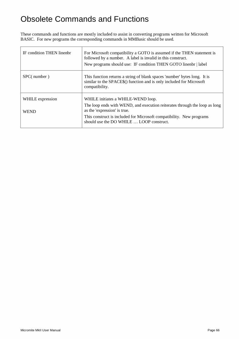
Micromite MkII User Manual Page 66
Obsolete Commands and Functions Detailed Listing These commands and functions are mostly included to assist in converting programs written for Microsoft BASIC. For new programs the corresponding commands in MMBasic should be used.
IF condition THEN linenbr For Microsoft compatibility a GOTO is assumed if the THEN statement is followed by a number. A label is invalid in this construct. New programs should use: IF condition THEN GOTO linenbr | label
SPC( number ) This function returns a string of blank spaces 'number' bytes long. It is similar to the SPACE$() function and is only included for Microsoft compatibility.
WHILE expression WEND
WHILE initiates a WHILE-WEND loop. The loop ends with WEND, and execution reiterates through the loop as long as the 'expression' is true. This construct is included for Microsoft compatibility. New programs should use the DO WHILE … LOOP construct.
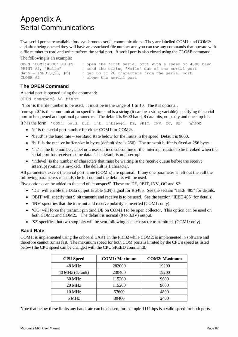
Micromite MkII User Manual Page 67
Appendix A – Serial Communications Serial Communications Two serial ports are available for asynchronous serial communications. They are labelled COM1: and COM2: and after being opened they will have an associated file number and you can use any commands that operate with a file number to read and write to/from the serial port. A serial port is also closed using the CLOSE command. The following is an example: OPEN "COM1:4800" AS #5 ‘ open the first serial port with a speed of 4800 baud PRINT #5, "Hello" ‘ send the string "Hello" out of the serial port dat$ = INPUT$(20, #5) ‘ get up to 20 characters from the serial port CLOSE #5 ‘ close the serial port
The OPEN Command A serial port is opened using the command: OPEN comspec$ AS #fnbr
‘fnbr’ is the file number to be used. It must be in the range of 1 to 10. The # is optional. ‘comspec$’ is the communication specification and is a string (it can be a string variable) specifying the serial port to be opened and optional parameters. The default is 9600 baud, 8 data bits, no parity and one stop bit. It has the form "COMn: baud, buf, int, intlevel, DE, 9BIT, INV, OC, S2" where:
‘n’ is the serial port number for either COM1: or COM2:. ‘baud’ is the baud rate – see Baud Rate below for the limits in the speed Default is 9600. ‘buf’ is the receive buffer size in bytes (default size is 256). The transmit buffer is fixed at 256 bytes. ‘int’ is the line number, label or a user defined subroutine of the interrupt routine to be invoked when the
serial port has received some data. The default is no interrupt. ‘intlevel’ is the number of characters that must be waiting in the receive queue before the receive
interrupt routine is invoked. The default is 1 character. All parameters except the serial port name (COMn:) are optional. If any one parameter is left out then all the following parameters must also be left out and the defaults will be used. Five options can be added to the end of 'comspec$' These are DE, 9BIT, INV, OC and S2:
‘DE’ will enable the Data output Enable (EN) signal for RS485. See the section "IEEE 485" for details. '9BIT' will specify that 9 bit transmit and receive is to be used. See the section "IEEE 485" for details. 'INV' specifies that the transmit and receive polarity is inverted (COM1: only). ‘OC’ will force the transmit pin (and DE on COM1:) to be open collector. This option can be used on
both COM1: and COM2:. The default is normal (0 to 3.3V) output. 'S2' specifies that two stop bits will be sent following each character transmitted. (COM1: only)
Baud Rate COM1: is implemented using the onboard UART in the PIC32 while COM2: is implemented in software and therefore cannot run as fast. The maximum speed for both COM ports is limited by the CPU's speed as listed below (the CPU speed can be changed with the CPU SPEED command):
CPU Speed COM1: Maximum COM2: Maximum 48 MHz 282000 19200
40 MHz (default) 230400 19200 30 MHz 115200 9600 20 MHz 115200 9600 10 MHz 57600 4800 5 MHz 38400 2400
Note that below these limits any baud rate can be chosen, for example 1111 bps is a valid speed for both ports.
Micromite MkII User Manual Page 68
Input/Output Pin Allocation On the 28-pin chip COM1: uses pin 22 for receive data (data in) and pin 21 for transmit data (data out). If data enable (ENABLE) is specified pin 7 will be used for this signal (the pin will be turned into an output). COM2: uses pin 10 for receive data (data in) and pin 9 for transmit data (data out). On the 48 pin chip COM1: uses pin 9 for receive data (data in) and pin 8 for transmit data (data out). If data enable (ENABLE) is specified pin 24 will be used for this signal (the pin will be turned into an output). COM2: uses pin 31 for receive data (data in) and pin 30 for transmit data (data out). When a serial port is opened the pins used by the port will be automatically set to input or output as required and the SETPIN and PIN commands will be disabled for the pins. When the port is closed (using the CLOSE command) all pins used by the serial port will be set to a not-configured state and the SETPIN command can then be used to reconfigure them. The signal polarity is standard for devices running at TTL voltages (for RS232 voltages see below). Idle is voltage high, the start bit is voltage low, data uses a high voltage for logic 1 and the stop bit is voltage high. These signal levels allow you to directly connect to devices like GPS modules (which generally use TTL voltage levels).
Examples Opening a serial port using all the defaults: OPEN "COM2:" AS #2 Opening a serial port specifying only the baud rate (4800 bits per second): OPEN "COM2:4800" AS #1
Opening a serial port specifying the baud rate (9600 bits per second) and receive buffer size (1KB): OPEN "COM1:9600, 1024" AS #8
The same as above but with two stop bits enabled: OPEN "COM1:9600, 1024, S2" AS #8
An example specifying everything including an interrupt, an interrupt level, inverted and two stop bits: OPEN "COM1:19200, 1024, ComIntLabel, 256, INV, S2" AS #5
Reading and Writing Once a serial port has been opened you can use any command or function that uses a file number to write and read from the port. Generally the PRINT command is the best method for transmitting data and the INPUT$() function is the most convenient way of getting data that has been received. When using the INPUT$() function the number of characters specified will be the maximum number of characters returned but it could be less if there are less characters in the receive buffer. In fact the INPUT$() function will immediately return an empty string if there are no characters available in the receive buffer. The LOC() function is also handy; it will return the number of characters waiting in the receive buffer (ie, the number characters that can be retrieved by the INPUT$() function). The EOF() function will return true if there are no characters waiting. The LOF() function will return the space (in characters) remaining in the transmit buffer. When outputting to a serial port (ie, using PRINT #n, dat) the command will pause if the output buffer is full and wait until there is sufficient space to place the new data in the buffer before returning. If the receive buffer overflows with incoming data the serial port will automatically discard the oldest data to make room for the new data. Serial ports can be closed with the CLOSE command. This will discard any characters waiting in the buffers, free the memory used by the buffers, cancel the interrupt (if set) and set all pins used by the port to the not configured state. A serial port is also automatically closed when commands such as RUN and NEW are issued.
Interrupts The interrupt routine (if specified) will operate the same as a general interrupt on an external I/O pin (see page 7 for a description). Return from the interrupt is via the IRETURN statement except where a user defined subroutine is used (in that case END SUB or EXIT SUB is used). Note that subroutine parameters cannot be used. When using interrupts you need to be aware that it will take some time for MMBasic to respond to the interrupt and more characters could have arrived in the meantime, especially at high baud rates. So, for example, if you have specified the interrupt level as 200 characters and a buffer of 256 characters then quite easily the buffer will have overflowed by the time the interrupt routine can read the data. In this case the buffer should be increased to 512 characters or more.
Micromite MkII User Manual Page 69
IEEE 485 The 'DE' option in the OPEN comspec$ for COM1: specifies that the Data output Enable (ENABLE) signal for the IEEE 485 protocol will be generated. This signal will appear on pin 7 on the 28-pin chip and is normally high. Just before a byte is transmitted this output will go low and when the byte has finished transmission the output will go high again. Note that this polarity is the opposite of that used in the Maximite family and an inverter is normally required to drive the DE input of an IEEE 485 transceiver. Many IEEE 485 systems also use 9 bits of data for transmit and receive. The 9th bit is used to indicate that an address is being sent or received. To accommodate this the '9BIT' option in the OPEN comspec$ for COM1: can be used. With this option all data sent must be sent in pairs of bytes – the first byte is the 9th bit and the second is the data (the other 8 bits). The first byte should be either the ASCII character '1' to indicate that the 9th bit should be set or '0' for not set. This 9th bit is then applied to the second byte in the pair and together they represent the 9 bits of data to send. For example, the following fragment of code will send three 9 bit data items. The first is an address (bit 9 is high) and the second two are the data (bit 9 is low):
OPEN "COM1: 4800, 9BIT" as #1 PRINT "1" + CHR$(211); PRINT "0" + CHR$(23); PRINT "0" + CHR$(0);
Note that in the PRINT commands the automatic CR/LF is suppressed by the use of the semicolon. Received data is similar. The 9bit data is translated into two characters – the first is the ASCII character '1' or '0' indicating the state of the 9th bit in the data received and the second character is the other 8 bits. This means that a BASIC program must read the data as pairs and apply logic to determine the value of the 9th bit (the first character) and then take the appropriate action with the second character. For example:
IF LOC(#1) >= 2 THEN ' check that we have at least two bytes A$ = INPUT$(1, #1) : B$ = INPUT$(1, #1) IF A$ = "1" THEN ' B$ contains an address ELSE ' B$ contains some data ENDIF ENDIF
MMBasic does not check that data is printed or read to/from the COM port in pairs. If your program inadvertently sends or reads a single character it will disrupt all subsequent communications. Note also that in 9 bit mode the size of the transmit and receive buffers are effectively halved because each 9 bit data item is stored as two bytes.
Low Cost RS-232 Interface The RS-232 signalling system is used by modems, hardwired serial ports on a PC, test equipment, etc. It is the same as the serial TTL system used on the Micromite with two exceptions:
The voltage levels of RS-232 are +12V and -12V where TTL serial uses +3.3V and zero volts. The signalling is inverted (the idle voltage is -12V, the start bit is +12V, etc).
It is possible to purchase cheap RS-232 to TTL converters on the Internet but it would be handy if the Micromite could directly interface to RS-232. The first issue is that the signalling polarity is inverted with respect to TTL. On the Micromite COM1: can be specified to invert the transmit and receive signal (the 'INV' option) so that is an easy fix. For the receive data (that is the ±12V signal from the remote RS-232 device) it is easy to limit the voltage using a series resistor of (say) 22KΩ and a diode that will clamp the positive voltage to the 3.3V rail. The input impedance of the Micromite is very high so the resistor will not cause a voltage drop but it does mean that when the signal swings to the maximum +12V it will be safely clipped by the diode and when it swings to -12V it will be clipped by the protection diode internal to the Micromite. For the transmit signal (from the Micromite to the RS-232 device) you can connect this directly to the input of the remote device. The Micromite will only swing the signal from zero to 3.3V but most RS-232 inputs have a threshold of about +1V so the Micromite's signal will still be interpreted as a valid signal.
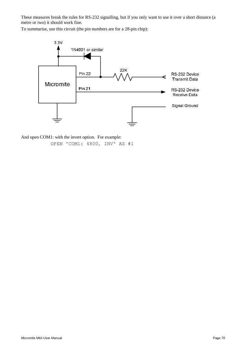
Micromite MkII User Manual Page 70
These measures break the rules for RS-232 signalling, but if you only want to use it over a short distance (a metre or two) it should work fine. To summarise, use this circuit (the pin numbers are for a 28-pin chip):
And open COM1: with the invert option. For example:
OPEN "COM1: 4800, INV" AS #1
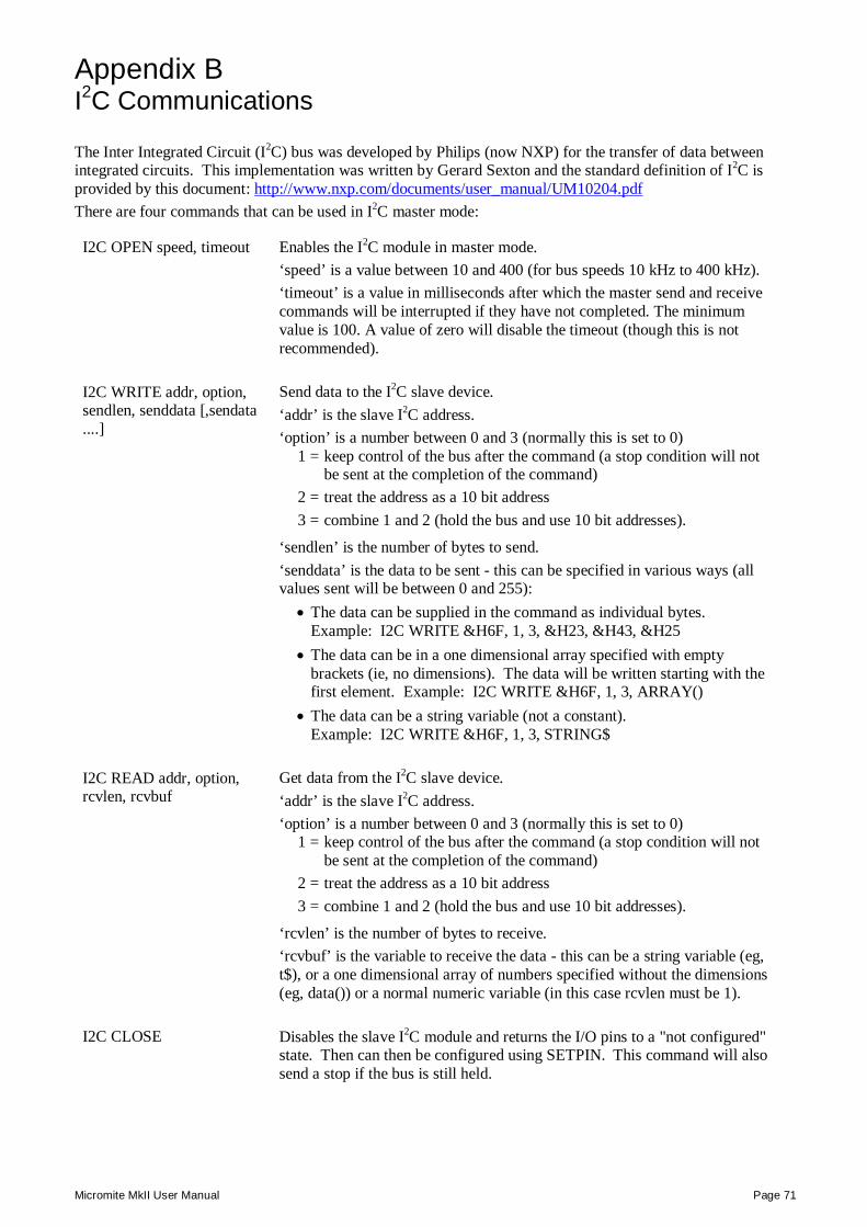
Micromite MkII User Manual Page 71
Appendix B – I2C Communications I2C Communications The Inter Integrated Circuit (I2C) bus was developed by Philips (now NXP) for the transfer of data between integrated circuits. This implementation was written by Gerard Sexton and the standard definition of I2C is provided by this document: http://www.nxp.com/documents/user_manual/UM10204.pdf There are four commands that can be used in I2C master mode:
I2C OPEN speed, timeout Enables the I2C module in master mode. ‘speed’ is a value between 10 and 400 (for bus speeds 10 kHz to 400 kHz). ‘timeout’ is a value in milliseconds after which the master send and receive commands will be interrupted if they have not completed. The minimum value is 100. A value of zero will disable the timeout (though this is not recommended).
I2C WRITE addr, option, sendlen, senddata [,sendata ....]
Send data to the I2C slave device. ‘addr’ is the slave I2C address. ‘option’ is a number between 0 and 3 (normally this is set to 0)
1 = keep control of the bus after the command (a stop condition will not be sent at the completion of the command)
2 = treat the address as a 10 bit address 3 = combine 1 and 2 (hold the bus and use 10 bit addresses).
‘sendlen’ is the number of bytes to send. ‘senddata’ is the data to be sent - this can be specified in various ways (all values sent will be between 0 and 255):
The data can be supplied in the command as individual bytes. Example: I2C WRITE &H6F, 1, 3, &H23, &H43, &H25
The data can be in a one dimensional array specified with empty brackets (ie, no dimensions). The data will be written starting with the first element. Example: I2C WRITE &H6F, 1, 3, ARRAY()
The data can be a string variable (not a constant). Example: I2C WRITE &H6F, 1, 3, STRING$
I2C READ addr, option, rcvlen, rcvbuf
Get data from the I2C slave device. ‘addr’ is the slave I2C address. ‘option’ is a number between 0 and 3 (normally this is set to 0)
1 = keep control of the bus after the command (a stop condition will not be sent at the completion of the command)
2 = treat the address as a 10 bit address 3 = combine 1 and 2 (hold the bus and use 10 bit addresses).
‘rcvlen’ is the number of bytes to receive. ‘rcvbuf’ is the variable to receive the data - this can be a string variable (eg, t$), or a one dimensional array of numbers specified without the dimensions (eg, data()) or a normal numeric variable (in this case rcvlen must be 1).
I2C CLOSE Disables the slave I2C module and returns the I/O pins to a "not configured" state. Then can then be configured using SETPIN. This command will also send a stop if the bus is still held.
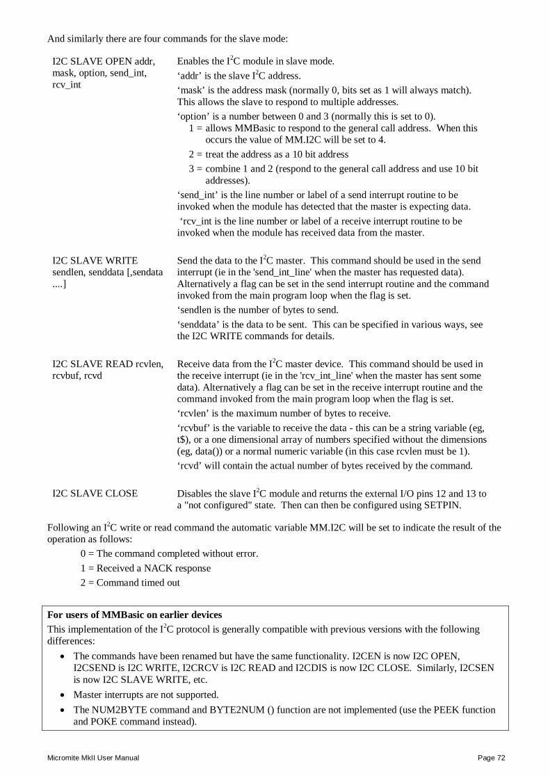
Micromite MkII User Manual Page 72
And similarly there are four commands for the slave mode:
I2C SLAVE OPEN addr, mask, option, send_int, rcv_int
Enables the I2C module in slave mode. ‘addr’ is the slave I2C address. ‘mask’ is the address mask (normally 0, bits set as 1 will always match). This allows the slave to respond to multiple addresses. ‘option’ is a number between 0 and 3 (normally this is set to 0).
1 = allows MMBasic to respond to the general call address. When this occurs the value of MM.I2C will be set to 4.
2 = treat the address as a 10 bit address 3 = combine 1 and 2 (respond to the general call address and use 10 bit
addresses). ‘send_int’ is the line number or label of a send interrupt routine to be invoked when the module has detected that the master is expecting data. ‘rcv_int is the line number or label of a receive interrupt routine to be invoked when the module has received data from the master.
I2C SLAVE WRITE sendlen, senddata [,sendata ....]
Send the data to the I2C master. This command should be used in the send interrupt (ie in the 'send_int_line' when the master has requested data). Alternatively a flag can be set in the send interrupt routine and the command invoked from the main program loop when the flag is set. ‘sendlen is the number of bytes to send. ‘senddata’ is the data to be sent. This can be specified in various ways, see the I2C WRITE commands for details.
I2C SLAVE READ rcvlen, rcvbuf, rcvd
Receive data from the I2C master device. This command should be used in the receive interrupt (ie in the 'rcv_int_line' when the master has sent some data). Alternatively a flag can be set in the receive interrupt routine and the command invoked from the main program loop when the flag is set. ‘rcvlen’ is the maximum number of bytes to receive. ‘rcvbuf’ is the variable to receive the data - this can be a string variable (eg, t$), or a one dimensional array of numbers specified without the dimensions (eg, data()) or a normal numeric variable (in this case rcvlen must be 1). ‘rcvd’ will contain the actual number of bytes received by the command.
I2C SLAVE CLOSE Disables the slave I2C module and returns the external I/O pins 12 and 13 to a "not configured" state. Then can then be configured using SETPIN.
Following an I2C write or read command the automatic variable MM.I2C will be set to indicate the result of the operation as follows:
0 = The command completed without error. 1 = Received a NACK response 2 = Command timed out
For users of MMBasic on earlier devices This implementation of the I2C protocol is generally compatible with previous versions with the following differences:
The commands have been renamed but have the same functionality. I2CEN is now I2C OPEN, I2CSEND is I2C WRITE, I2CRCV is I2C READ and I2CDIS is now I2C CLOSE. Similarly, I2CSEN is now I2C SLAVE WRITE, etc.
Master interrupts are not supported. The NUM2BYTE command and BYTE2NUM () function are not implemented (use the PEEK function
and POKE command instead).
Micromite MkII User Manual Page 73
7 and 8 Bit Addressing The standard addresses used in these commands are 7-bit addresses (without the read/write bit). MMBasic will add the read/write bit and manipulate it accordingly during transfers. Some vendors provide 8-bit addresses which include the read/write bit. You can determine if this is the case because they will provide one address for writing to the slave device and another for reading from the slave. In these situations you should only use the top seven bits of the address. For example: If the read address is 9B (hex) and the write address is 9A (hex) then using only the top seven bits will give you an address of 4D (hex). A simple way of finding the address is to take the 8 bit write address and divide it by 2. Another indicator that a vendor is using 8-bit addresses instead of 7-bit addresses is to check the address range. All 7-bit addresses should be in the range of 08 to 77 (hex). If your slave address is greater than this range then probably your vendor has specified an 8-bit address.
10 Bit Addressing 10-bit addressing was designed to be compatible with 7-bit addresses, allowing developers to mix the two types of devices on a single bus. Devices that use 10-bit addresses will be clearly identified as such in their data sheets. In 10-bit addressing the slave address is sent in two bytes with the first byte beginning with a special bit pattern to indicate that a 10 bit address is being used. This process is automatically managed by MMBasic when the 'option' argument is set for 10-bit addressing. 10-bit addresses can be in the range of 0 to 3FF (hex).
Master/Slave Modes The master and slave modes can be enabled simultaneously; however, once a master command is in progress, the slave function will be "idle" until the master releases the bus. Similarly, if a slave command is in progress, the master commands will be unavailable until the slave transaction completes. In master mode, the I2C send and receive commands will not return until the command completes or a timeout occurs (if the timeout option has been specified). The slave mode uses an MMBasic interrupt to signal a change in status and in this routine the Micromite should write/read the data as specified by the I2C master. This operates the same as a general interrupt on an external I/O pin. Return from the interrupt is via the IRETURN statement except where a user defined subroutine is used (in that case END SUB or EXIT SUB is used).
I/O Pins On a 28-pin chip pin 18 becomes the I2C data line (SDA) and pin 17 the clock (SCL). On a 44-pin chip pin 1 becomes the I2C data line (SDA) and pin 44 the clock (SCL). Both of these pins should have external pullup resistors installed (typical values are 10KΩ for 100KHz or 2KΩ for 400 kHz). When the I2C CLOSE command is used the I/O pins are reset to a "not configured" state. Then can then be configured as per normal using SETPIN. When running the I2C bus at above 150 kHz the cabling between the devices becomes important. Ideally the cables should be as short as possible (to reduce capacitance) and also the data and clock lines should not run next to each other but have a ground wire between them (to reduce crosstalk). If the data line is not stable when the clock is high, or the clock line is jittery, the I2C peripherals can get "confused" and end up locking the bus (normally by holding the clock line low). If you do not need the higher speeds then operating at 100 kHz is the safest choice.
Example I2C is ideally suited for communications between integrated circuits. As an example, there might be an occasion when a single Micromite or Maximite does not have enough serial ports, I/O pins, or whatever for a particular application. In that case a Micromite could be used as a slave to provide the extra facilities. This example converts a Micromite into a general purpose I/O expansion chip with 17 I/O pins that can be dynamically configured (by the master) as analog inputs or digital input/outputs. The routines on the master are simple to use (SSETPIN to configure the slave I/O and SPIN() to control it) and the program running on the master need not know that the physical I/O pins reside on another chip. All communications are done via I2C.
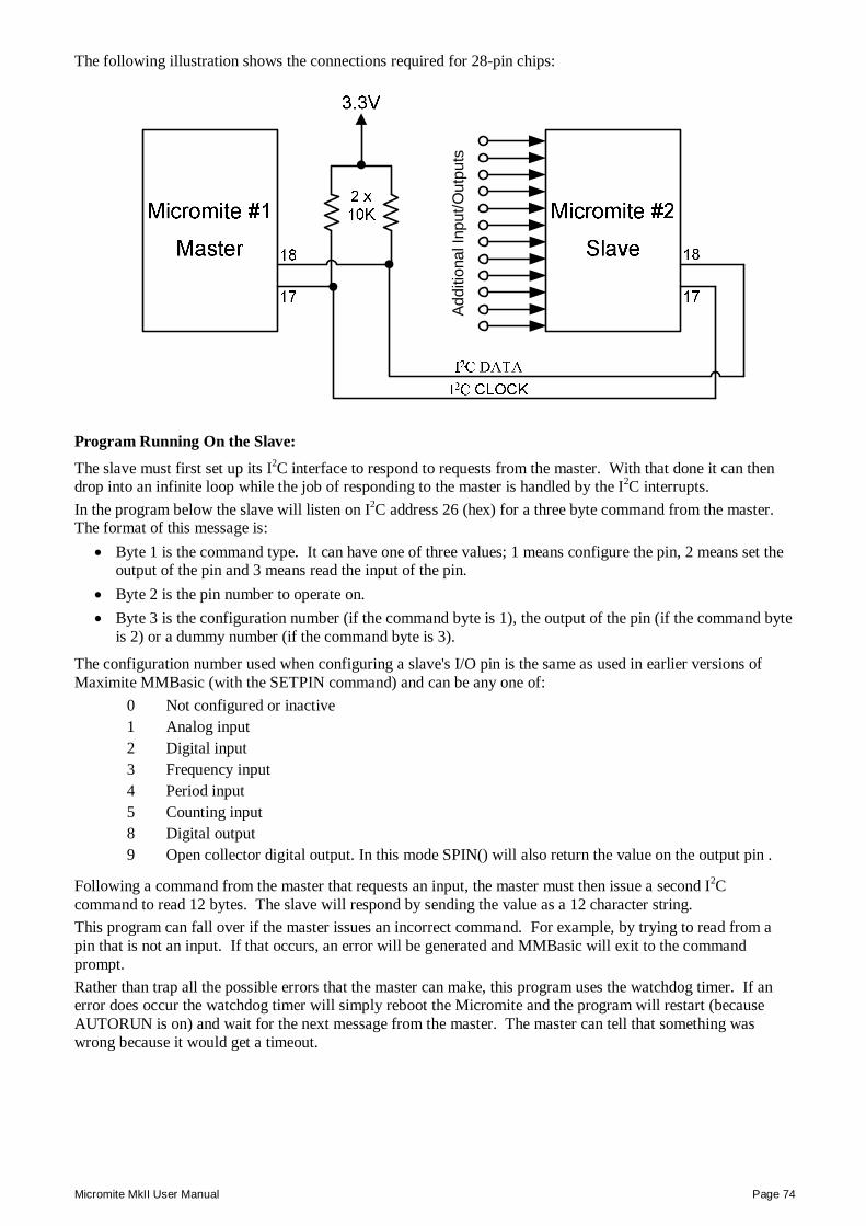
Micromite MkII User Manual Page 74
The following illustration shows the connections required for 28-pin chips:
Addi
tiona
l Inp
ut/O
utpu
ts
Program Running On the Slave:
The slave must first set up its I2C interface to respond to requests from the master. With that done it can then drop into an infinite loop while the job of responding to the master is handled by the I2C interrupts. In the program below the slave will listen on I2C address 26 (hex) for a three byte command from the master. The format of this message is:
Byte 1 is the command type. It can have one of three values; 1 means configure the pin, 2 means set the output of the pin and 3 means read the input of the pin.
Byte 2 is the pin number to operate on. Byte 3 is the configuration number (if the command byte is 1), the output of the pin (if the command byte
is 2) or a dummy number (if the command byte is 3).
The configuration number used when configuring a slave's I/O pin is the same as used in earlier versions of Maximite MMBasic (with the SETPIN command) and can be any one of:
0 Not configured or inactive 1 Analog input 2 Digital input 3 Frequency input 4 Period input 5 Counting input 8 Digital output 9 Open collector digital output. In this mode SPIN() will also return the value on the output pin .
Following a command from the master that requests an input, the master must then issue a second I2C command to read 12 bytes. The slave will respond by sending the value as a 12 character string. This program can fall over if the master issues an incorrect command. For example, by trying to read from a pin that is not an input. If that occurs, an error will be generated and MMBasic will exit to the command prompt. Rather than trap all the possible errors that the master can make, this program uses the watchdog timer. If an error does occur the watchdog timer will simply reboot the Micromite and the program will restart (because AUTORUN is on) and wait for the next message from the master. The master can tell that something was wrong because it would get a timeout.
Micromite MkII User Manual Page 75
This is the complete program running on the slave:
OPTION AUTORUN ON DIM msg(2) ' array used to hold the message I2C SLAVE OPEN &H26, 0, 0, WriteD, ReadD ' slave's address is 26 (hex) DO ' the program loops forever WATCHDOG 1000 ' this will recover from errors LOOP ReadD: ' received a message I2C SLAVE READ 3, msg(), recvd ' get the message into the array IF msg(0) = 1 THEN ' command = 1 SETPIN msg(1), msg(2) ' configure the I/O pin ELSEIF msg(0) = 2 THEN ' command = 2 PIN(msg(1)) = msg(2) ' set the I/O pin's output ELSE ' the command must be 3 s$ = str$(pin(msg(1))) + Space$(12) ' get the input on the I/O pin ENDIF IRETURN ' return from the interrupt WriteD: ' request from the master I2C SLAVE WRITE 12, s$ ' send the last measurement IRETURN ' return from the interrupt
Interface Routines On the Master:
These routines can be run on another Micromite or a Maximite or some other computer with an I2C interface. They assume that the slave Micromite is listening on I2C address 26 (hex). If necessary these can be modified to access multiple Micromites (with different addresses), all acting as expansion chips and providing an almost unlimited expansion capability. There are two subroutines and one function that together are used to control the slave:
SSETPIN pin, cfg This subroutine will setup an I/O pin on the slave. It operates the same as the MMBasic SETPIN command and the possible values for 'cfg' are listed above.
SPIN pin, output This subroutine will set the output of the slave's pin to 'output' (ie, high or low).
nn = SPIN(pin) This function will return the value of the input on the slave's I/O pin.
For example, to display the voltage on pin 3 of the slave you would use: SSETPIN 3, 1 PRINT SPIN(3)
As another example, to flash a LED connected to pin 15 of the slave you would use: SSETPIN 15, 8 SPIN 15, 1 PAUSE 300 SPIN 15, 0
These are the three routines:
' configure an I/O pin on the slave SUB SSETPIN pinnbr, cfg I2C OPEN 100, 1000 I2C WRITE &H26, 0, 3, 1, pinnbr, cfg IF MM.I2C THEN ERROR "Slave did not respond" I2C CLOSE END SUB
Micromite MkII User Manual Page 76
' set the output of an I/O pin on the slave SUB SPIN pinnbr, dat I2C OPEN 100, 1000 I2C WRITE &H26, 0, 3, 2, pinnbr, dat IF MM.I2C THEN ERROR "Slave did not respond" I2C CLOSE END SUB ' get the input of an I/O pin on the slave FUNCTION SPIN(pinnbr) LOCAL t$ I2C OPEN 100, 1000 I2C WRITE &H26, 0, 3, 3, pinnbr, 0 I2C READ &H26, 0, 12, t$ IF MM.I2C THEN ERROR "Slave did not respond" I2C CLOSE SPin = VAL(t$) END FUNCTION
These use the new names for the I2C functions so, on the Maximite, version 4.5 or later of MMBasic will be required. Earlier versions of MMBasic on the Maximite will also work but the I2C command names will have to be changed to the old standard. Also, the method of getting the string from the slave in SPIN(pinnbr) will have to be changed (earlier versions did not support receiving data into a string variable).
Micromite MkII User Manual Page 77
Appendix C – 1-Wire Communications 1-Wire Communications The 1-Wire protocol was developed by Dallas Semiconductor to communicate with chips using a single signalling line. This implementation was written for MMBasic by Gerard Sexton.
There are three commands that you can use: ONEWIRE RESET pin Reset the 1-Wire bus ONEWIRE WRITE pin, flag, length, data [, data…] Send a number of bytes ONEWIRE READ pin, flag, length, data [, data…] Get a number of bytes
Where: pin - The Micromite I/O pin to use. It can be any pin capable of digital I/O. flag - A combination of the following options:
1 - Send reset before command 2 - Send reset after command 4 - Only send/recv a bit instead of a byte of data 8 - Invoke a strong pullup after the command (the pin will be set high and open drain disabled)
length - Length of data to send or receive data - Data to send or variable to receive. The number of data items must agree with the length parameter.
And the automatic variable
MM.ONEWIRE Returns true if a device was found Note: The CPU speed must be 10MHz or above. After the command is executed, the I/O pin will be set to the not configured state unless flag option 8 is used. When a reset is requested the automatic variable MM.ONEWIRE will return true if a device was found. This will occur with the ONEWIRE RESET command and the ONEWIRE READ and ONEWIRE WRITE commands if a reset was requested (flag = 1 or 2).
For users of MMBasic on earlier devices This implementation of the 1-Wire protocol is generally compatible with previous versions with the following differences:
The commands are now two words where previously they were one word. For example, OWWRITE is now ONEWIRE WRITE.
You cannot use an array or string variable for 'data'. One or more numeric variables are required. The reset command (ONEWIRE RESET) does not accept a 'presence' variable (use the MM.ONEWIRE
variable instead). The OWSEARCH command and the OWCRC8() and OWCRC16() functions are not implemented.
The 1-Wire protocol is often used in communicating with the DS18B20 temperature measuring sensor and to help in that regard MMBasic includes the DS18B20() function which provides convenient method of directly reading the temperature of a DS18B20 without using these functions.
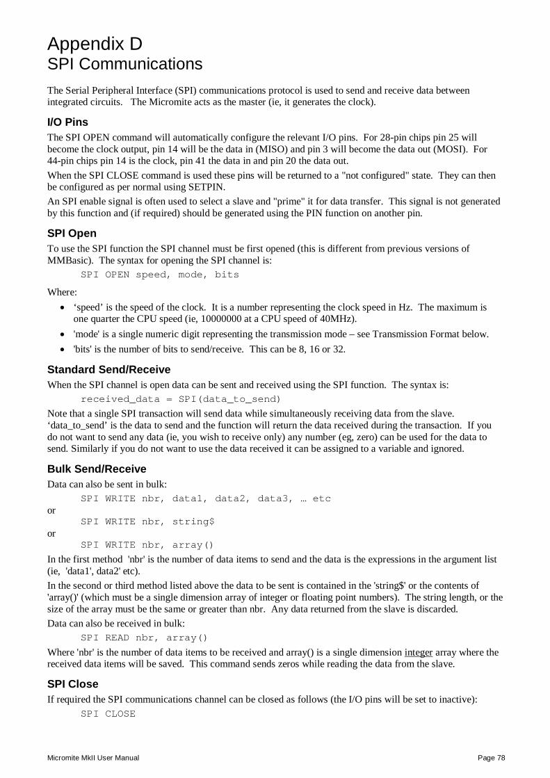
Micromite MkII User Manual Page 78
Appendix D – SPI Communications SPI Communications The Serial Peripheral Interface (SPI) communications protocol is used to send and receive data between integrated circuits. The Micromite acts as the master (ie, it generates the clock).
I/O Pins The SPI OPEN command will automatically configure the relevant I/O pins. For 28-pin chips pin 25 will become the clock output, pin 14 will be the data in (MISO) and pin 3 will become the data out (MOSI). For 44-pin chips pin 14 is the clock, pin 41 the data in and pin 20 the data out. When the SPI CLOSE command is used these pins will be returned to a "not configured" state. They can then be configured as per normal using SETPIN. An SPI enable signal is often used to select a slave and "prime" it for data transfer. This signal is not generated by this function and (if required) should be generated using the PIN function on another pin.
SPI Open To use the SPI function the SPI channel must be first opened (this is different from previous versions of MMBasic). The syntax for opening the SPI channel is:
SPI OPEN speed, mode, bits
Where: ‘speed’ is the speed of the clock. It is a number representing the clock speed in Hz. The maximum is
one quarter the CPU speed (ie, 10000000 at a CPU speed of 40MHz). 'mode' is a single numeric digit representing the transmission mode – see Transmission Format below. 'bits' is the number of bits to send/receive. This can be 8, 16 or 32.
Standard Send/Receive When the SPI channel is open data can be sent and received using the SPI function. The syntax is:
received_data = SPI(data_to_send) Note that a single SPI transaction will send data while simultaneously receiving data from the slave. ‘data_to_send’ is the data to send and the function will return the data received during the transaction. If you do not want to send any data (ie, you wish to receive only) any number (eg, zero) can be used for the data to send. Similarly if you do not want to use the data received it can be assigned to a variable and ignored.
Bulk Send/Receive Data can also be sent in bulk:
SPI WRITE nbr, data1, data2, data3, … etc or
SPI WRITE nbr, string$ or
SPI WRITE nbr, array()
In the first method 'nbr' is the number of data items to send and the data is the expressions in the argument list (ie, 'data1', data2' etc). In the second or third method listed above the data to be sent is contained in the 'string$' or the contents of 'array()' (which must be a single dimension array of integer or floating point numbers). The string length, or the size of the array must be the same or greater than nbr. Any data returned from the slave is discarded. Data can also be received in bulk:
SPI READ nbr, array()
Where 'nbr' is the number of data items to be received and array() is a single dimension integer array where the received data items will be saved. This command sends zeros while reading the data from the slave.
SPI Close If required the SPI communications channel can be closed as follows (the I/O pins will be set to inactive):
SPI CLOSE
Micromite MkII User Manual Page 79
Transmission Format The most significant bit is sent and received first. The format of the transmission can be specified by the 'mode' as shown below. Mode 3 is the most common format.
Mode Description CPOL CPHA
0 Clock is active high, data is captured on the rising edge and output on the falling edge 0 0
1 Clock is active high, data is captured on the falling edge and output on the rising edge 0 1
2 Clock is active low, data is captured on the falling edge and output on the rising edge 1 0
3 Clock is active low, data is captured on the rising edge and output on the falling edge 1 1
For a more complete explanation see: http://en.wikipedia.org/wiki/Serial_Peripheral_Interface_Bus
Examples The following example will send the command 80 (hex) and receive two bytes from the slave SPI device using the standard send/receive function: PIN(10) = 1 : SETPIN 10, DOUT ‘ pin 10 will be used as the enable signal SPI OPEN 5000000, 3, 8 ' speed is 5MHz and the data size is 8 bits PIN(10) = 0 ‘ assert the enable line (active low) junk = SPI(&H80) ‘ send the command and ignore the return byte1 = SPI(0) ‘ get the first byte from the slave byte2 = SPI(0) ‘ get the second byte from the slave PIN(10) = 1 ‘ deselect the slave SPI CLOSE ' and close the channel
The following is similar to the example given above but this time the transfer is made using the bulk send/receive commands: OPTION BASE 1 ' our array will start with the index 1 DIM data%(2) ' define the array for receiving the data PIN(10) = 1 : SETPIN 10, DOUT ‘ pin 10 will be used as the enable signal SPI OPEN 5000000, 3, 8 ' speed is 5MHz and the data size is 8 bits PIN(10) = 0 ‘ assert the enable line (active low) SPI WRITE 1, &H80 ‘ send the command SPI READ 2, data%() ‘ get two bytes from the slave PIN(10) = 1 ‘ deselect the slave SPI CLOSE ' and close the channel