Embed Size (px)
Citation preview

Micromite eXtreme
Manual
MMBasic Ver 5.3b10v4
For updates to this manual and more details on MMBasic go to http://geoffg.net/micromite.html
or http://mmbasic.com
This manual is distributed under a Creative Commons Attribution-NonCommercial-ShareAlike 3.0 Australia license (CC BY-NC-SA 3.0)

Micromite eXtreme Manual Page 2
The Micromite eXtreme is a new addition to the Micromite family using the 100 and 144-pin PIC32 MZ microcontrollers. The Micromite eXtreme firmware implements all the features of the standard Micromite and the Micromite Plus as described in the Micromite User Manual and the Micromite Plus Manual. It also has a number of additional features and they are described in this document.
The focus of this manual is to describe just the features that are unique to the Micromite eXtreme. For general Micromite programming you should refer to the Micromite User Manual and the Micromite Plus Manual in addition to this manual.
Contents
Introduction ............................................................................................................................. 3
Micromite Family Summary .................................................................................................... 4
Suitable Microcontrollers ........................................................................................................ 5
Typical Circuit ......................................................................................................................... 6
Programming the Firmware .................................................................................................... 7
100-pin Micromite eXtreme Pinouts ........................................................................................ 8
144-pin Micromite eXtreme Pinouts ...................................................................................... 11
VGA Driver ........................................................................................................................... 15
Mouse Support ..................................................................................................................... 16
Unique Micromite eXtreme Features .................................................................................... 16
Commands (Micromite eXtreme Only) ................................................................................. 19
Functions (Micromite eXtreme Only) .................................................................................... 22

Micromite eXtreme Manual Page 3
Introduction This section provides an introduction for users who are familiar with the Micromite and the Micromite Plus and need a summary of the extra features in the Micromite eXtreme.
The Micromite eXtreme is an extension of the standard Micromite and the Micromite Plus; all features of these two versions are also in the Micromite eXtreme. This includes features of the BASIC language, input/output, communications, etc. Some commands have changed slightly (for example the CPU command) but for the main part Micromite programs will run unchanged on the Micromite eXtreme.
The following summarises the new features in the Micromite eXtreme as compared to the standard Micromite and the Micromite Plus:
PIC32 MZ Processor
The Micromite eXtreme is based on the Microchip PIC32MZ 32 bit microcontroller. This chip is available in 100 and 144-pin surface mount packages and is up to five times faster and has up to ten times the program space of the MX series used in the standard Micromite.
High Speed Double Precision Floating Point
The Micromite eXtreme uses the built in hardware floating point capability of the PIC32MZ which is much faster than floating point on the standard Micromite and uses double precision floating point.
I/O Pins
The 100-pin Micromite eXtreme has up to 71 free I/O pins with 40 analog capable and the 144-pin chip has up to 115 free I/O pins with 50 analogue capable. All analogue pins use a 12-bit analogue to digital conversion rather than 10-bit on the standard Micromite.
The Micromite eXtreme has two I2C ports, three SPI ports, six PWM channels and up to four serial COM ports. All serial COM ports are high speed (over 1,000,000 baud).
High Speed LCD Panels
Like the Micromite Plus the Micromite eXtreme supports ten different sized LCD display panels from 1.44" to 8". In addition it can drive displays using the SSD1963 controller in 16-bit parallel mode to achieve an even greater display update speed.
VGA Output
The Micromite eXtreme can drive a VGA display in 640 x 480 pixels or 640 x 400 (widescreen) with eight colours. All the graphics commands and GUI controls available in the Micromite Plus will also work on the VGA output.
Mouse Input
The Micromite eXtreme can support a PS2 mouse which can be used to activate on screen GUI controls. This feature will work with touch sensitive LCD displays (it works in parallel with the touch sensitivity) but it is especially useful with VGA monitors that do not normally incorporate a touch sensitive surface.
Transparency and BLIT function
On certain LCD display panels or the VGA output the Micromite eXtreme supports transparent text and the BLIT command. These allow text to be written over a background image or graphic items to be moved over the background without erasing or damaging the background.
Sound Output
Using the Micromite Plus you can play stereo WAV files stored on the SD card. You can also generate precise sine waves with selectable frequencies from 1Hz to 20KHz.
Micromite eXtreme Manual Page 4
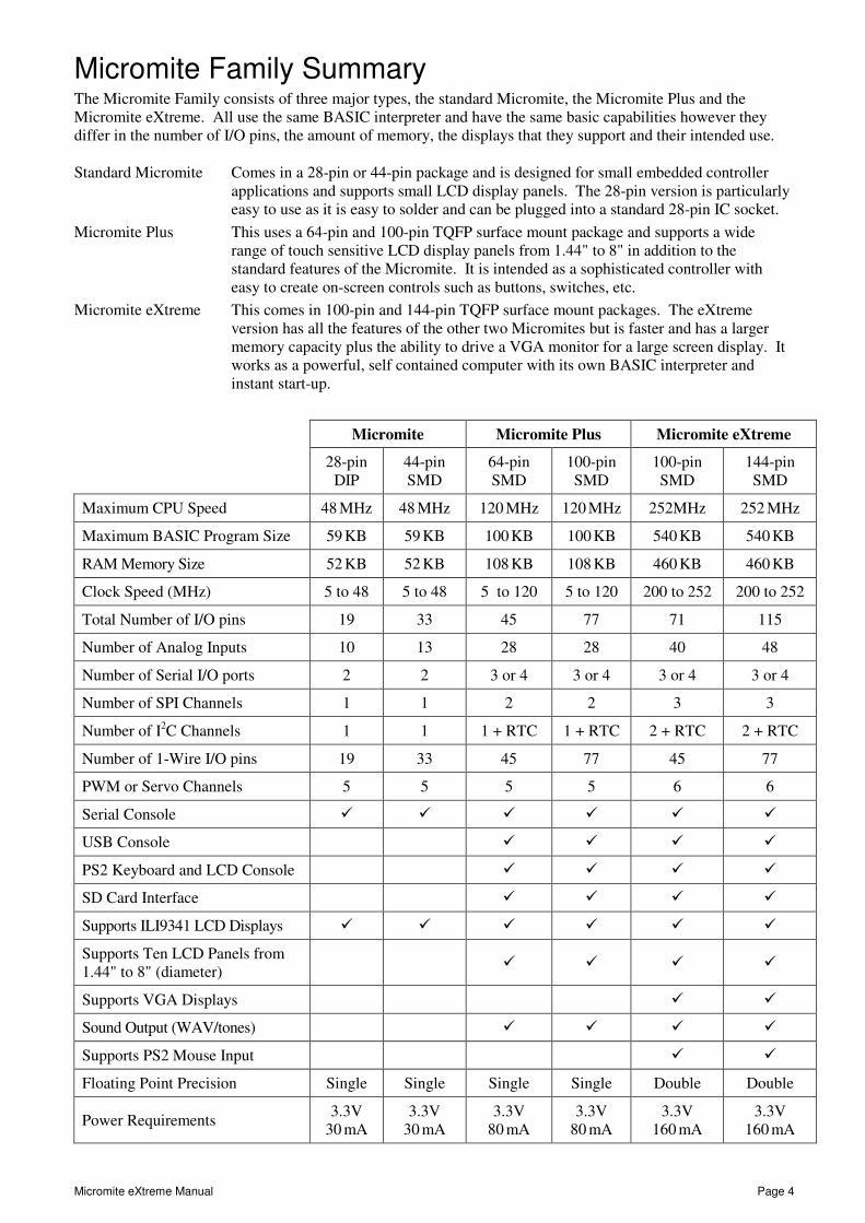
Micromite Family Summary The Micromite Family consists of three major types, the standard Micromite, the Micromite Plus and the Micromite eXtreme. All use the same BASIC interpreter and have the same basic capabilities however they differ in the number of I/O pins, the amount of memory, the displays that they support and their intended use.
Standard Micromite Comes in a 28-pin or 44-pin package and is designed for small embedded controller applications and supports small LCD display panels. The 28-pin version is particularly easy to use as it is easy to solder and can be plugged into a standard 28-pin IC socket.
Micromite Plus This uses a 64-pin and 100-pin TQFP surface mount package and supports a wide range of touch sensitive LCD display panels from 1.44" to 8" in addition to the standard features of the Micromite. It is intended as a sophisticated controller with easy to create on-screen controls such as buttons, switches, etc.
Micromite eXtreme This comes in 100-pin and 144-pin TQFP surface mount packages. The eXtreme version has all the features of the other two Micromites but is faster and has a larger memory capacity plus the ability to drive a VGA monitor for a large screen display. It works as a powerful, self contained computer with its own BASIC interpreter and instant start-up.
Micromite Micromite Plus Micromite eXtreme
28-pin
DIP 44-pin SMD
64-pin SMD
100-pin SMD
100-pin SMD
144-pin SMD
Maximum CPU Speed 48 MHz 48 MHz 120 MHz 120 MHz 252MHz 252 MHz
Maximum BASIC Program Size 59 KB 59 KB 100 KB 100 KB 540 KB 540 KB
RAM Memory Size 52 KB 52 KB 108 KB 108 KB 460 KB 460 KB
Clock Speed (MHz) 5 to 48 5 to 48 5 to 120 5 to 120 200 to 252 200 to 252
Total Number of I/O pins 19 33 45 77 71 115
Number of Analog Inputs 10 13 28 28 40 48
Number of Serial I/O ports 2 2 3 or 4 3 or 4 3 or 4 3 or 4
Number of SPI Channels 1 1 2 2 3 3
Number of I2C Channels 1 1 1 + RTC 1 + RTC 2 + RTC 2 + RTC
Number of 1-Wire I/O pins 19 33 45 77 45 77
PWM or Servo Channels 5 5 5 5 6 6
Serial Console � � � � � �
USB Console � � � �
PS2 Keyboard and LCD Console � � � �
SD Card Interface � � � �
Supports ILI9341 LCD Displays � � � � � �
Supports Ten LCD Panels from 1.44" to 8" (diameter)
� � � �
Supports VGA Displays � �
Sound Output (WAV/tones) � � � �
Supports PS2 Mouse Input � �
Floating Point Precision Single Single Single Single Double Double
Power Requirements 3.3V
30 mA 3.3V
30 mA 3.3V
80 mA 3.3V
80 mA 3.3V
160 mA 3.3V
160 mA

Micromite eXtreme Manual Page 5
Suitable Microcontrollers
The microcontroller used in the Micromite eXtreme is the PIC32MZ EF series manufactured by Microchip. There are two chip sizes (100-pin and 144-pin) with two frequency specifications (200 MHz and 252 MHz).
The default clock speed of the Micromite eXtreme is 200 MHz however this can be changed with a configura-tion option to 252 MHz if required. The firmware will automatically adjust for either the 100 or 144 pin version.
The recommended chips are:
PIC32MZ2048EFG100-I/PL 100-pin LQFP package (0.5 mm pin pitch) – maximum speed 200 MHz
PIC32MZ2048EFG144-I/PH 144-pin TQFP package (0.4 mm pin pitch) – maximum speed 200 MHz
PIC32MZ2048EFH100-250I/PL 100-pin LQFP package (0.5 mm pin pitch) – maximum speed 252 MHz
PIC32MZ2048EFH144-250I/PH 144-pin TQFP package (0.4 mm pin pitch) – maximum speed 252 MHz
The chips PIC32MZ2048EFM100-I/PF and PIC32MZ2048EFM144-I/PH can also be used at 200 MHz.
See http://microchip.com for the data sheets.
100-pin Test and Development Board
The best development board for the 100-pin 200 MHz chip is the SnadPIC MZ, PIC32MZ EF MCU Starter Kit. This can be ordered with either the PIC32MZ2048EFG100-I/PF or PIC32MZ2048EFH100-I/PF processor (both are similar, the latter has a CAN facility but that is not supported by MMBasic).
If you are developing your own board it would be worth using the SnadPIC board for guidance.
SnadPIC boards can be purchased from:
http://www.microcontroller-board.com/snadpic-board-32-bit/24-snadpic-mz-pic32mz-ef-mcu-starter-kit-pic32mz2048efg100.html
or
http://www.ebay.com.au/itm/PIC32MZ-USB-OTG-Microchip-Development-Board-Starter-kit-SD-Card-SnadPIC-MZ-/181805050475
or search ebay.com for "SnadPIC MZ"
144-pin Test and Development Board
The website micromite.org is planning to produce a suitable board for the 144-pin chip. This board will mount on the back of a 7" LCD display panel and include connectors for VGA, PS2 keyboard, PS2 mouse and USB.
Check http://micromite.org/ for details.

Micromite eXtreme Manual Page 6
Typical Circuit
An example of the required circuit for a Micromite eXtreme is given below:
Notes:
1. If the USB module is not used, this pin may be connected to VSS.
2. As an option, instead of a hard-wired connection, an inductor (L1) can be substituted between VDD and AVDD to improve ADC noise rejection. The inductor impedance should be less than 1ohm and the inductor capacity greater than 10 mA. Alternatively a 10ohm resistor could be substituted for L1. Typical values for R, R1, and C would be 10Kohm, 1Kohm, and 0.1uF
3. A 24MHz crystal oscillator must be connected to the OSC1 pin. e.g. Epson SG8002DCPHB24MHZ. See the pinout below for the pin number

Micromite eXtreme Manual Page 7
Programming the Firmware Programming the 100 and 144-pin Micromite eXtreme is similar to programming the 28-pin standard Micromite described in the Micromite User Manual.
Refer to the following table for the pin connections to a PICkit 3 programmer:
PICkit 3
Pins Description
100-pin Micromite eXtreme pin
numbers
144-pin Micromite eXtreme pin
numbers
1 - MCLR Master Reset (active low) 15 20
2 - Vcc Power Supply (3.3V) 14, 37, 46, 62, 74, 83, 93, 30 (AVDD), 52 (VUSB3V3)
18, 33, 55, 64, 88, 107, 122, 137, 41 (AVDD), 74 (VUSB3V3)
3 - GND Ground 13, 36, 45, 53, 63, 75, 84, 92, 31 (AVSS)
17, 32, 54, 63, 75, 89, 108, 123, 136, 42(AVSS)
4 - PGD Programming Data 25 or 27 36 or 38
5 - PGC Programming Clock 24 or 26 35 or 37
6 - NC Not used
Notes:
• PDD/PGC must be used in matched pairs as aligned vertically in the table
• A pullup resistor of 10K is required between MCLR and Vcc.
• An oscillator is not required to program these chips and will be ignored if present
• The microcontroller being programmed can be powered by the PICkit 3 but it is recommended that a separate power supply be used. When the PICkit 3 supplies the power pin 2 (Vcc) on the PICkit 3 will become an output supplying power to the chip being programmed

Micromite eXtreme Manual Page 8
100-pin Micromite eXtreme Pinouts
Pin Features
1 ANALOG_IN DIGITAL_IN DIGITAL_OUT
2 ANALOG_IN DIGITAL_IN DIGITAL_OUT
3 ANALOG_IN DIGITAL_IN DIGITAL_OUT PWM-2C SOUND-LEFT
4 ANALOG_IN DIGITAL_IN DIGITAL_OUT
5 ANALOG_IN DIGITAL_IN DIGITAL_OUT
6 ANALOG_IN DIGITAL_IN DIGITAL_OUT COUNT PWM-2A
7 ANALOG_IN DIGITAL_IN DIGITAL_OUT COUNT
8 ANALOG_IN DIGITAL_IN DIGITAL_OUT COUNT
9 ANALOG_IN DIGITAL_IN DIGITAL_OUT COUNT IR
10 ANALOG_IN DIGITAL_IN DIGITAL_OUT SPI2-CLK
11 ANALOG_IN DIGITAL_IN DIGITAL_OUT I2C-SDA
12 ANALOG_IN DIGITAL_IN DIGITAL_OUT I2C-CLK
13 VSS
14 VDD
15 MCLR
16 ANALOG_IN DIGITAL_IN DIGITAL_OUT PWM-1C
17 ANALOG_IN DIGITAL_IN DIGITAL_OUT
18 ANALOG_IN DIGITAL_IN DIGITAL_OUT SOUND-RIGHT
19 ANALOG_IN DIGITAL_IN DIGITAL_OUT VGA-BLU-SS
20 ANALOG_IN DIGITAL_IN DIGITAL_OUT SSD1963-D5
21 ANALOG_IN DIGITAL_IN DIGITAL_OUT SSD1963-D4 VGA-VSYNC
22 ANALOG_IN DIGITAL_IN DIGITAL_OUT SSD1963-D3
23 ANALOG_IN DIGITAL_IN DIGITAL_OUT SSD1963-D2
24 ANALOG_IN DIGITAL_IN DIGITAL_OUT SSD1963-D1
25 ANALOG_IN DIGITAL_IN DIGITAL_OUT SSD1963-D0
26 ANALOG_IN DIGITAL_IN DIGITAL_OUT SSD1963-D6
27 ANALOG_IN DIGITAL_IN DIGITAL_OUT SSD1963-D7
28 ANALOG_IN DIGITAL_IN DIGITAL_OUT
29 ANALOG_IN DIGITAL_IN DIGITAL_OUT
30 AVDD
31 AVSS
32 ANALOG_IN DIGITAL_IN DIGITAL_OUT SSD1963-D8 VGA-GRN-OUT
33 ANALOG_IN DIGITAL_IN DIGITAL_OUT SSD1963-D9 VGA-BLU-OUT
34 ANALOG_IN DIGITAL_IN DIGITAL_OUT SSD1963-D10 VGA-RED-OUT
35 ANALOG_IN DIGITAL_IN DIGITAL_OUT SSD1963-D11
36 VSS
37 VDD

Micromite eXtreme Manual Page 9
38 ANALOG_IN DIGITAL_IN DIGITAL_OUT
39 ANALOG_IN DIGITAL_IN DIGITAL_OUT COM1-EN VGA-BLU-CLK
40 ANALOG_IN DIGITAL_IN DIGITAL_OUT PWM-2B
41 ANALOG_IN DIGITAL_IN DIGITAL_OUT SSD1963-D12
42 ANALOG_IN DIGITAL_IN DIGITAL_OUT SSD1963-D13
43 ANALOG_IN DIGITAL_IN DIGITAL_OUT SSD1963-D14 VGA-RED-CLK
44 ANALOG_IN DIGITAL_IN DIGITAL_OUT SSD1963-D15 VGA-RED-SS
45 VSS
46 VDD
47 ANALOG_IN DIGITAL_IN DIGITAL_OUT COM1-RX
48 ANALOG_IN DIGITAL_IN DIGITAL_OUT VGA-GRN-CLK
49 OSC1
50 OSC2 - unused
51 VBUS
52 VDD
53 VSS
54 D-
55 D+
56 USBID
57 DIGITAL_IN DIGITAL_OUT COM3-TX
58 DIGITAL_IN DIGITAL_OUT COM3-RX
59 DIGITAL_IN DIGITAL_OUT Snadpic-SD-CD I2C2-CLK
60 DIGITAL_IN DIGITAL_OUT I2C2-SDA
61 DIGITAL_IN DIGITAL_OUT
62 VDD
63 VSS
64 DIGITAL_IN DIGITAL_OUT VGA-GRN-SS
65 DIGITAL_IN DIGITAL_OUT COM1-TX
66 DIGITAL_IN DIGITAL_OUT SPI2-OUT
67 DIGITAL_IN DIGITAL_OUT SPI3-OUT
68 DIGITAL_IN DIGITAL_OUT
69 DIGITAL_IN DIGITAL_OUT SPI3-CLK
70 DIGITAL_IN DIGITAL_OUT SPI3-IN
71 DIGITAL_IN DIGITAL_OUT PWM-1B
72 DIGITAL_IN DIGITAL_OUT SPI2-IN
73 DIGITAL_IN DIGITAL_OUT PWM-1A
74 VDD
75 VSS
76 DIGITAL_IN DIGITAL_OUT SPI-CLK
77 DIGITAL_IN DIGITAL_OUT SPI-IN

Micromite eXtreme Manual Page 10
78 DIGITAL_IN DIGITAL_OUT SPI-OUT
79 DIGITAL_IN DIGITAL_OUT VGA-HSYNC
80 DIGITAL_IN DIGITAL_OUT
81 DIGITAL_IN DIGITAL_OUT Snadpic-SD-CS
82 DIGITAL_IN DIGITAL_OUT
83 VDD
84 VSS
85 DIGITAL_IN DIGITAL_OUT COM4-TX CONSOLE-TX
86 DIGITAL_IN DIGITAL_OUT COM4-RX CONSOLE-RX
87 DIGITAL_IN DIGITAL_OUT COM2-TX
88 DIGITAL_IN DIGITAL_OUT COM2-RX
89 DIGITAL_IN DIGITAL_OUT KBD-CLK
90 DIGITAL_IN DIGITAL_OUT KBD-DAT
91 DIGITAL_IN DIGITAL_OUT MOUSE-CLK
92 VSS
93 VDD
94 DIGITAL_IN DIGITAL_OUT MOUSE-DAT
95 DIGITAL_IN DIGITAL_OUT SSD1963-RESET
96 DIGITAL_IN DIGITAL_OUT SSD1963-RS
97 DIGITAL_IN DIGITAL_OUT SSD1963-WR
98 DIGITAL_IN DIGITAL_OUT
99 DIGITAL_IN DIGITAL_OUT HEARTBEAT
100 ANALOG_IN DIGITAL_IN DIGITAL_OUT

Micromite eXtreme Manual Page 11
144-pin Micromite eXtreme Pinouts
Pin Features
1 ANALOG_IN DIGITAL_IN DIGITAL_OUT
2 ANALOG_IN DIGITAL_IN DIGITAL_OUT
3 ANALOG_IN DIGITAL_IN DIGITAL_OUT PWM-2C
4 ANALOG_IN DIGITAL_IN DIGITAL_OUT
5 ANALOG_IN DIGITAL_IN DIGITAL_OUT
6 ANALOG_IN DIGITAL_IN DIGITAL_OUT COUNT3
7 ANALOG_IN DIGITAL_IN DIGITAL_OUT SSD1963-DB8
8 ANALOG_IN DIGITAL_IN DIGITAL_OUT SSD1963-DB9
9 DIGITAL_IN DIGITAL_OUT SSD1963-DB12
10 DIGITAL_IN DIGITAL_OUT SSD1963-DB10
11 ANALOG_IN DIGITAL_IN DIGITAL_OUT COUNT1
12 ANALOG_IN DIGITAL_IN DIGITAL_OUT COUNT2
13 ANALOG_IN DIGITAL_IN DIGITAL_OUT COUNT4-IR
14 ANALOG_IN DIGITAL_IN DIGITAL_OUT SPI2 CLK
15 ANALOG_IN DIGITAL_IN DIGITAL_OUT I2C-SDA
16 ANALOG_IN DIGITAL_IN DIGITAL_OUT I2C-CLK
17 GND
18 VCC
19 DIGITAL_IN DIGITAL_OUT HEARTBEAT
20 RESET
21 ANALOG_IN DIGITAL_IN DIGITAL_OUT
22 ANALOG_IN DIGITAL_IN DIGITAL_OUT
23 ANALOG_IN DIGITAL_IN DIGITAL_OUT COM1-EN
24 ANALOG_IN DIGITAL_IN DIGITAL_OUT VGA-HSYNC
25 ANALOG_IN DIGITAL_IN DIGITAL_OUT
26 ANALOG_IN DIGITAL_IN DIGITAL_OUT VGA-VSYNC
27 ANALOG_IN DIGITAL_IN DIGITAL_OUT SSD1963-DB11
28 DIGITAL_IN DIGITAL_OUT SSD1963-DB13
29 DIGITAL_IN DIGITAL_OUT SSD1963-DB14
30 DIGITAL_IN DIGITAL_OUT SSD1963-DB15
31 ANALOG_IN DIGITAL_IN DIGITAL_OUT
32 GND
33 VCC
34 ANALOG_IN DIGITAL_IN DIGITAL_OUT SOUND-LEFT
35 ANALOG_IN DIGITAL_IN DIGITAL_OUT SOUND-RIGHT
36 ANALOG_IN DIGITAL_IN DIGITAL_OUT
37 ANALOG_IN DIGITAL_IN DIGITAL_OUT

Micromite eXtreme Manual Page 12
38 ANALOG_IN DIGITAL_IN DIGITAL_OUT
39 ANALOG_IN DIGITAL_IN DIGITAL_OUT
40 ANALOG_IN DIGITAL_IN DIGITAL_OUT
41 AVDD
42 AVSS
43 ANALOG_IN DIGITAL_IN DIGITAL_OUT
44 ANALOG_IN DIGITAL_IN DIGITAL_OUT
45 DIGITAL_IN DIGITAL_OUT
46 DIGITAL_IN DIGITAL_OUT
47 ANALOG_IN DIGITAL_IN DIGITAL_OUT VGA-GRN-OUT
48 ANALOG_IN DIGITAL_IN DIGITAL_OUT VGA-BLU-OUT
49 ANALOG_IN DIGITAL_IN DIGITAL_OUT VGA-RED-OUT
50 ANALOG_IN DIGITAL_IN DIGITAL_OUT
51 DIGITAL_IN DIGITAL_OUT
52 DIGITAL_IN DIGITAL_OUT
53 DIGITAL_IN DIGITAL_OUT
54 GND
55 VCC
56 ANALOG_IN DIGITAL_IN DIGITAL_OUT
57 ANALOG_IN DIGITAL_IN DIGITAL_OUT VGA-CLK
58 ANALOG_IN DIGITAL_IN DIGITAL_OUT PWM-2B
59 ANALOG_IN DIGITAL_IN DIGITAL_OUT
60 ANALOG_IN DIGITAL_IN DIGITAL_OUT
61 ANALOG_IN DIGITAL_IN DIGITAL_OUT VGA-CLK
62 ANALOG_IN DIGITAL_IN DIGITAL_OUT VGA-HSYNC
63 GND
64 VCC
65 ANALOG_IN DIGITAL_IN DIGITAL_OUT
66 ANALOG_IN DIGITAL_IN DIGITAL_OUT
67 ANALOG_IN DIGITAL_IN DIGITAL_OUT
68 DIGITAL_IN DIGITAL_OUT
69 ANALOG_IN DIGITAL_IN DIGITAL_OUT COM1-RX
70 ANALOG_IN DIGITAL_IN DIGITAL_OUT VGA-CLK
71 OSC1
72 OSC2 - unused
73 VBUS
74 VCC
75 GND
76 USBD-
77 USBD+

Micromite eXtreme Manual Page 13
78 USBID
79 DIGITAL_IN DIGITAL_OUT COM3-TX
80 DIGITAL_IN DIGITAL_OUT COM3-RX
81 DIGITAL_IN DIGITAL_OUT
82 DIGITAL_IN DIGITAL_OUT
83 DIGITAL_IN DIGITAL_OUT
84 DIGITAL_IN DIGITAL_OUT
85 DIGITAL_IN DIGITAL_OUT I2C2-SCK
86 DIGITAL_IN DIGITAL_OUT I2C2-SDA
87 DIGITAL_IN DIGITAL_OUT
88 VCC
89 GND
90 DIGITAL_IN DIGITAL_OUT VGA-HSYNC
91 DIGITAL_IN DIGITAL_OUT COM1-TX
92 DIGITAL_IN DIGITAL_OUT
93 DIGITAL_IN DIGITAL_OUT
94 DIGITAL_IN DIGITAL_OUT
95 DIGITAL_IN DIGITAL_OUT SPI2-OUT
96 DIGITAL_IN DIGITAL_OUT SPI3-OUT
97 DIGITAL_IN DIGITAL_OUT
98 DIGITAL_IN DIGITAL_OUT SPI3-CLK
99 DIGITAL_IN DIGITAL_OUT SPI3-IN
100 DIGITAL_IN DIGITAL_OUT
101 DIGITAL_IN DIGITAL_OUT
102 DIGITAL_IN DIGITAL_OUT
103 DIGITAL_IN DIGITAL_OUT
104 DIGITAL_IN DIGITAL_OUT PWM-1B
105 DIGITAL_IN DIGITAL_OUT SPI2-IN
106 DIGITAL_IN DIGITAL_OUT PWM-1A
107 VCC
108 GND
109 DIGITAL_IN DIGITAL_OUT SPI-CLK
110 DIGITAL_IN DIGITAL_OUT SPI-IN
111 DIGITAL_IN DIGITAL_OUT SPI-OUT
112 DIGITAL_IN DIGITAL_OUT VGA-HSYNC
113 DIGITAL_IN DIGITAL_OUT
114 DIGITAL_IN DIGITAL_OUT SSD1963-DB0
115 DIGITAL_IN DIGITAL_OUT SSD1963-DB1
116 DIGITAL_IN DIGITAL_OUT SSD1963-DB2
117 DIGITAL_IN DIGITAL_OUT SSD1963-DB3

Micromite eXtreme Manual Page 14
118 DIGITAL_IN DIGITAL_OUT
119 DIGITAL_IN DIGITAL_OUT PWM-1C
120 DIGITAL_IN DIGITAL_OUT PWM-2A
121 DIGITAL_IN DIGITAL_OUT
122 VCC
123 GND
124 DIGITAL_IN DIGITAL_OUT Console-TX COM4-TX
125 DIGITAL_IN DIGITAL_OUT Console-RX COM4-RX
126 DIGITAL_IN DIGITAL_OUT
127 DIGITAL_IN DIGITAL_OUT COM2-TX
128 DIGITAL_IN DIGITAL_OUT COM2-RX
129 DIGITAL_IN DIGITAL_OUT KB-CLK
130 DIGITAL_IN DIGITAL_OUT KB-DAT
131 DIGITAL_IN DIGITAL_OUT SSD1963-DB4
132 DIGITAL_IN DIGITAL_OUT SSD1963-DB5
133 DIGITAL_IN DIGITAL_OUT SSD1963-DB6
134 DIGITAL_IN DIGITAL_OUT SSD1963-DB7
135 DIGITAL_IN DIGITAL_OUT MOUSE-CLK
136 GND
137 VCC
138 DIGITAL_IN DIGITAL_OUT MOUSE-DAT
139 DIGITAL_IN DIGITAL_OUT
140 DIGITAL_IN DIGITAL_OUT
141 DIGITAL_IN DIGITAL_OUT
142 DIGITAL_IN DIGITAL_OUT
143 DIGITAL_IN DIGITAL_OUT
144 ANALOG_IN DIGITAL_IN DIGITAL_OUT

Micromite eXtreme Manual Page 15
VGA Driver The Micromite eXtreme can drive a standard VGA monitor by internally generating the necessary VGA signals (red, green, sync, etc). When a VGA monitor is connected and configured the VGA output works exactly the same as a connected LCD display panel – this means that all graphics commands, GUI objects, etc can be used as described in the Micromite and Micromite Plus manuals.
The features of the VGA driver are:
• 640 x 480 pixel output
• Optional 640 x 400 widescreen output
• Eight colours (red, blue, green, yellow, cyan, magenta, black, white)
• Works with all graphics and GUI commands.
• Supports any command/features that use transparency (transparent text and the BLIT command).
• Works as the console with 80 characters x 36 lines and will work with the EDIT command
VGA Connections
The connections for the VGA monitor are shown below:
The I/O pins VGA-RED-CLK, VGA-GRN-CLK, VGA-BLU-CLK must be left unconnected.
For the actual pin numbers refer to the pinout tables earlier in this manual.
Note that the diodes must be high speed signal types like the 1N4148 (not general purpose power diodes).
Configuring VGA Output
The command to enable the standard VGA 640 x 480 pixel output is:
OPTION LCDPANEL VGA
and to enable the widescreen format (640 x 400 pixels) the command is:
OPTION LCDPANEL VGA, 16
These commands only need to be run once as the parameters are stored in non volatile memory. Every time the Micromite is restarted MMBasic will automatically initialise the display ready for use. If the VGA output is no longer required the command OPTION LCDPANEL DISABLE can be used which will disable the VGA feature and return the I/O pins for general use.
If the VGA monitor is also to be used as the console the normal command can be used to enable this:
OPTION LCDPANEL CONSOLE
Micromite eXtreme Manual Page 16
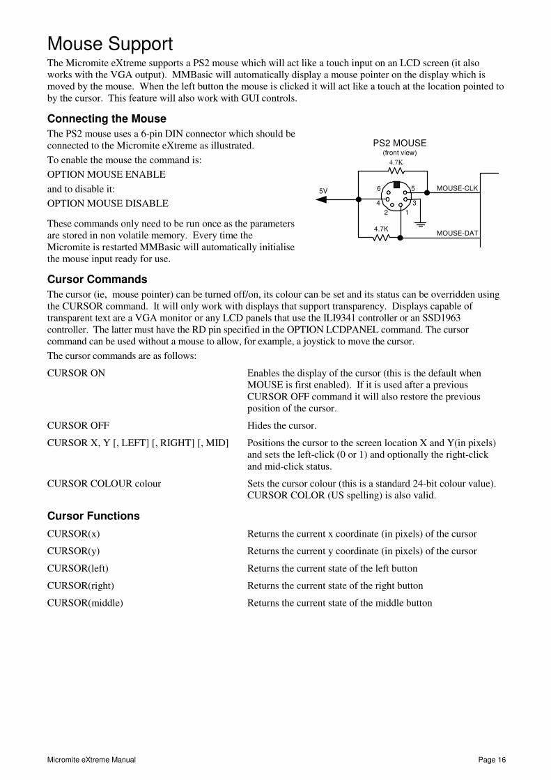
Mouse Support The Micromite eXtreme supports a PS2 mouse which will act like a touch input on an LCD screen (it also works with the VGA output). MMBasic will automatically display a mouse pointer on the display which is moved by the mouse. When the left button the mouse is clicked it will act like a touch at the location pointed to by the cursor. This feature will also work with GUI controls.
Connecting the Mouse
The PS2 mouse uses a 6-pin DIN connector which should be connected to the Micromite eXtreme as illustrated.
To enable the mouse the command is:
OPTION MOUSE ENABLE
and to disable it:
OPTION MOUSE DISABLE
These commands only need to be run once as the parameters are stored in non volatile memory. Every time the Micromite is restarted MMBasic will automatically initialise the mouse input ready for use.
Cursor Commands
The cursor (ie, mouse pointer) can be turned off/on, its colour can be set and its status can be overridden using the CURSOR command. It will only work with displays that support transparency. Displays capable of transparent text are a VGA monitor or any LCD panels that use the ILI9341 controller or an SSD1963 controller. The latter must have the RD pin specified in the OPTION LCDPANEL command. The cursor command can be used without a mouse to allow, for example, a joystick to move the cursor.
The cursor commands are as follows:
CURSOR ON Enables the display of the cursor (this is the default when MOUSE is first enabled). If it is used after a previous CURSOR OFF command it will also restore the previous position of the cursor.
CURSOR OFF Hides the cursor.
CURSOR X, Y [, LEFT] [, RIGHT] [, MID] Positions the cursor to the screen location X and Y(in pixels) and sets the left-click (0 or 1) and optionally the right-click and mid-click status.
CURSOR COLOUR colour Sets the cursor colour (this is a standard 24-bit colour value). CURSOR COLOR (US spelling) is also valid.
Cursor Functions
CURSOR(x) Returns the current x coordinate (in pixels) of the cursor
CURSOR(y) Returns the current y coordinate (in pixels) of the cursor
CURSOR(left) Returns the current state of the left button
CURSOR(right) Returns the current state of the right button
CURSOR(middle) Returns the current state of the middle button
PS2 MOUSE(front view)
2 1
4 3
6 5
MOUSE-DAT
MOUSE-CLK
4.7K
4.7K
5V

Micromite eXtreme Manual Page 17
Unique Micromite eXtreme Features
Double Precision Floating Point
The Micromite eXtreme uses the hardware floating point capability of the MZ series of chips and can therefore process floating point calculations faster than the Micromite and Micromite Plus. All floating point uses double precision calculations.
Nothing is required to enable this feature, it is automatically available.
Clock Speed Control
MMBasic can work with chips rated for 200 MHz or 252 MHz operation. By default the firmware will start running at 200 MHz however the 252 MHz clock speed can be selected with the command:
OPTION CPU 252
or the speed can be returned to 200 MHz with the command:
OPTION CPU 200
These commands change how MMBasic starts up and will cause a restart of the processor. The clock speed is saved in flash memory so the command only needs to be used once and will be automatically applied on startup.
Note: OPTION CPU 252 must only be used on chips specifically rated for 250Mhz operation. Use of this command on a 200MHz rated chip will cause MMBasic to stop running. The chip will then need to be re-programmed with the Micromite eXtreme firmware.
Apart from the increased processing speed the only difference with a chip running at 252 MHz is the ability to use WAV files recorded at 24 KHz and 48 KHz.
16-bit Interface to SSD1963 Based LCD Displays
The Micromite eXtreme can drive a SSD1963 display using a 16-bit parallel bus for extra speed. The extra I/O pins for this are listed as SSD1963-DB8 to SSD1963-DB15 on the pinout tables in this manual and they must be connected to the pins labelled DB8 to DB15 on the I/O connector on the SSD1963 display.
Note that in this mode the SSD1963 controller runs with a reduce colour range (65 thousand colours) compared to 16 million colours with the normal 8-bit interface.
To select the 16-bit bus the following controller names must be used with the OPTION LCDPANEL command when configuring the display:
• SSD1963_4_16 For a 4.3 inch display
• SSD1963_5_16 For a 5 inch display
• SSD1963_5A_16 For an alternative version of the 5 inch display if SSD1963_5 does not work
• SSD1963_7_16 For a 7 inch display
• SSD1963_7A_16 For an alternative version of the 7 inch display if SSD1963_7 does not work.
• SSD1963_8_16 For an 8 inch display.
GETSCANLINE Function
The GETSCANLINE() function can be used with displays using the SSD1963 controller to determine the line that the controller is writing to at that instant. Using this feature it is possible to update the display without causing a flicker by waiting until the controller is updating another area of the display before changing the graphics on a particular part of the display. It can be used like this:
If GETSCANLINE() > YCoord + MM.FontHeight THEN TEXT 0, YCoord, …
Two I2C Channels
The Micromite eXtreme supports two I2C channels. The second channel operates the same as the first, the only difference is that the commands use the notation I2C2 (for example I2C2 OPEN, etc).
Three SPI Channels
The Micromite eXtreme supports three SPI channels. The second and third channels operate the same as the first, the only difference is that the commands use the notation SPI2 and SPI3 (for example SPI3 WRITE, etc).
Note that by default, if the Micromite eXtreme is configured for a SPI based LCD panel, touch or an SD card then SPI2 will be unavailable to BASIC programs as these functions will use that channel.

Micromite eXtreme Manual Page 18
Alternate SPI Channel for the SD Card
The SPI channel used for the SD Card (if configured) defaults to the second channel (SPI2) however this can be changed by appending the SPI channel number to the end of the OPTION SDCARD command this:
OPTION SDCARD CSPIN [,CDPIN] [,WPPIN] [,SPIno]
'SPIno' is the SPI controller to use and can be 1, 2 or 2.
This is particularly useful with the SnadPIC MZ, PIC32MZ EF MCU Starter Kit is as it has the SD Card hardwired to controller 3. In that case the MMBasic command to configure the SD Card would be:
OPTION SDCARD 81, 59, , 3
Six PWM Channels
The second PWM controller (ie, PWM 2) supports three channels (the other versions of the Micromite only support two). The command to use all three channels is:
PWM 2, freq, 2A, 2B, 2C
Similarly the SERVO command can also control six channels with the extra channel available on controller 2:
SERVO 2 [, freq], 2A, 2B, 2C
Heartbeat
The heartbeat is an I/O pin which is pulsed off and on at a 1Hz rate. It is normally used to drive a LED to show that MMBasic is alive and running on the Micromite eXtreme.
The default is for it to be enabled however it can be disabled with:
OPTION HEARTBEAT DISABLE
If necessary it can be re enabled with:
OPTION HEARTBEAT ENABLE
These commands only needs to be run once as the parameters are stored in non volatile memory. Every time the Micromite is restarted MMBasic will automatically initialise the heartbeat feature.
Extended WAV File Playback
The Micromite eXtreme can play WAV files (like the Micromite Plus) however, if the eXtreme is configured to run at 252 Mhz it is also capable of playing WAV files recorded with sampling rates of 24 KHz and 48 KHz.
Random Number Generation
The Micromite eXtreme uses the hardware random number generator in the MZ series of chips to deliver true random numbers. This means that the RANDOMIZE command is no longer needed and is not supported.
MM.DEVICE$
On the Micromite eXtreme the read only variable MM.DEVICE$ will return "Micromite eXtreme".
OPTION VCC command
The Micromite eXtreme supports the OPTION VCC command. This allows the user to precisely set the supply voltage to the chip and is used in the calculation of voltages when using analog inputs e.g. OPTION VCC 3.15. The parameter is not saved and should be initialised either on the command line or in a program.
CPU command
The Micromite eXtreme does not support dynamically changing the CPU speed or the sleep function.
Accordingly the commands CPU speed and CPU SLEEP are not available. However the eXtreme does support “CPU SLEEP time” where time is specified in seconds.
The CPU speed of the Micromite eXtreme can be permanently set to 200 MHz or 252 MHz using the OPTION CPU command.
OPTION CONTROLS command
The Micromite eXtreme does not support the OPTION CONTROLS command instead the maximum number of GUI controls is set to 250.

Micromite eXtreme Manual Page 19
Commands (Micromite eXtreme Only) Detailed Listing
CLOSE [#]nbr [,[#]nbr] The text “GPS” can be substituted for [#]nbr to close a communications port used for a GPS receiver
CURSOR ON
CURSOR OFF
.
CURSOR X, Y [, LEFT] [, RIGHT] [, MID]
CURSOR COLOUR colour
Enables the display of the cursor (this is the default when MOUSE is first enabled). If it is used after a previous CURSOR OFF command it will also restore the previous position of the cursor.
Disables the display
Positions the cursor to the screen location X and Y(in pixels) and optionally sets the left-click (0 or 1), the right-click and mid-click status.
Sets the cursor colour (this is a standard 24-bit colour value). CURSOR COLOR (US spelling) is also valid.
I2C2 OPEN speed, timeout
[, PU
I2C2 WRITE addr, option, sendlen, senddata [,sendata
....]
I2C2 READ addr, option,
rcvlen, rcvbuf
I2C2 CLOSE
I2C2 SLAVE OPEN addr, mask, option, send_int,
rcv_int
I2C2 SLAVE WRITE sendlen, senddata [,sendata
....]
I2C2 SLAVE READ rcvlen,
rcvbuf, rcvd
I2C2 SLAVE CLOSE
See Appendix B of the Micromite User Manual
OPEN comspec$ AS GPS [,timezone_offset]
Will open a serial communications port for reading from a GPS receiver. See the GPS function for details. The timezone_offset parameter is used to convert UTC as received from the GPS to the local timezone. If omitted the timezone will default to UTC. The timezone_offset can be a any number between -12 and 14 allowing the time to be set correctly even for the Chatham Islands in New Zealand (UTC +12:45)

Micromite eXtreme Manual Page 20
OPTION CPU speed MMBasic can work with chips rated for 200 MHz or 252 MHz operation. By default the firmware will start running at 200 MHz however the 252
MHz clock speed can be selected with the command:
OPTION CPU 252
or the speed can be returned to 200 MHz with the command:
OPTION CPU 200
These commands change how MMBasic starts up and will cause a restart of the processor. The clock speed is saved in flash memory so the command only needs to be used once and will be automatically applied on startup.
Note: OPTION CPU 252 must only be used on chips specifically rated
for 250Mhz operation. Use of this command on a 200MHz rated chip will cause MMBasic to stop running. The chip will then need to be re-programmed with the Micromite eXtreme firmware.
Apart from the increased processing speed the only difference with a chip running at 252 MHz is the ability to use WAV files recorded at 24 KHz and 48 KHz.
OPTION HEARTBEAT ENABLE
OPTION HEARTBEAT DISABLE
Enables a heartbeat on an I/O pin which is pulsed onand off at a 1Hz rate. It is normally used to drive a LED to show that MMBasic is alive and running on the Micromite eXtreme.
Disables the heartbeat
OPTION LCDPANEL VGA [,16]
Enables output to a VGA display in 640 x 480 pixels or 640 x 400 (widescreen) with eight colours. All the graphics commands and GUI controls available in the Micromite Plus will also work on the VGA output. This command only needs to be run once as the parameters are stored in non volatile memory. When the Micromite is restarted the display will be automatically initialise ready for use. If the display is no longer required the command OPTION LCDPANEL DISABLE can be used to disable the VGA output and return the I/O pins for general use.
.
OPTION LCDPANEL SSD1963_n_16
Selects 16-bit bus operation of the various SSD1963 displays
OPTION MOUSE ENABLE
OPTION MOUSE DISABLE
Enables mouse control of the cursor.
Disables mouse control of the cursor and disables the cursor
These commands only needs to be run once as the parameters are stored in non volatile memory. Every time the Micromite is restarted MMBasic will automatically initialise the mouse input ready for use.
OPTION SDCARD CSPIN [,CDPIN] [,WPPIN] [,SPIno]
The SPI channel used for the SD Card (if configured) defaults to the second channel (SPI2) however this can be changed by appending the SPI channel number to the end of the OPTION SDCARD
OPTION VCC voltage
This allows the user to precisely set the supply voltage to the chip and is used in the calculation of voltages when using analog inputs. The parameter is not saved and should be initialised either on the command line or in a program.
PWM 2, freq, 2A, 2B, 2C See description of the PWM command in the Micromite User Manual. This command allows the specification of a frequency for a third PWM channel

Micromite eXtreme Manual Page 21
SERVO 2 [, freq], 2A, 2B, 2C See description of the SERVO command in the Micromite User Manual. This command allows the specification of a frequency for a third SERVO channel
SPI3 OPEN speed, mode, bits
SPI READ nbr, array()
SPI WRITE nbr, data1, data2, data3, … etc or SPI WRITE nbr, string$ or
SPI WRITE nbr, array()
SPI CLOSE
See Appendix D of the Micromite User Manual
Micromite eXtreme Manual Page 22
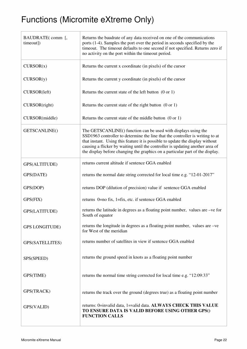
Functions (Micromite eXtreme Only) Detailed Listing
BAUDRATE( comm [, timeout])
Returns the baudrate of any data received on one of the communications ports (1-4). Samples the port over the period in seconds specified by the timeout. The timeout defaults to one second if not specified. Returns zero if no activity on the port within the timeout period.
CURSOR(x)
CURSOR(y)
CURSOR(left)
CURSOR(right)
CURSOR(middle)
Returns the current x coordinate (in pixels) of the cursor
Returns the current y coordinate (in pixels) of the cursor
Returns the current state of the left button (0 or 1)
Returns the current state of the right button (0 or 1)
Returns the current state of the middle button (0 or 1)
GETSCANLINE() The GETSCANLINE() function can be used with displays using the SSD1963 controller to determine the line that the controller is writing to at that instant. Using this feature it is possible to update the display without causing a flicker by waiting until the controller is updating another area of the display before changing the graphics on a particular part of the display.
GPS(ALTITUDE) GPS(DATE)
GPS(DOP)
GPS(FIX)
GPS(LATITUDE) GPS LONGITUDE) GPS(SATELLITES) SPS(SPEED)
GPS(TIME) GPS(TRACK) GPS(VALID)
returns current altitude if sentence GGA enabled
returns the normal date string corrected for local time e.g. “12-01-2017”
returns DOP (dilution of precision) value if sentence GGA enabled
returns 0=no fix, 1=fix, etc. if sentence GGA enabled returns the latitude in degrees as a floating point number, values are –ve for South of equator returns the longitude in degrees as a floating point number, values are –ve for West of the meridian returns number of satellites in view if sentence GGA enabled returns the ground speed in knots as a floating point number
returns the normal time string corrected for local time e.g. “12:09:33”
returns the track over the ground (degrees true) as a floating point number
returns: 0=invalid data, 1=valid data. ALWAYS CHECK THIS VALUE
TO ENSURE DATA IS VALID BEFORE USING OTHER GPS()
FUNCTION CALLS

Micromite eXtreme Manual Page 23
MM.DEVICE$ Returns “Micromite eXtreme”
SPI3(n) See Appendix D of the Micromite User Manual

![EXTREME PROGRAMMINGfse.studenttheses.ub.rug.nl/8856/1/Infor_Ma_2001_TdeJong.CV.pdf · EXTREME PROGRAMMING 3.1. WHAT IS EXTREME PROGRAMMING? According to vd)sitc [3], Extreme Programming](https://img.pdfslide.us/doc/110x75/6008914c858cab1a066c00ad/extreme-extreme-programming-31-what-is-extreme-programming-according-to-vdsitc.jpg)