Embed Size (px)
Citation preview
Microelectronic Circuits SJTU Yang Hua
Chapter 7 Frequency Response
Introduction7.1 s-Domain analysis: poles,zeros and bode plots7.2 the amplifier transfer function 7.3 Low-frequency response of the common-source and common-emitter amplifier7.4 High-frequency response of the CS and CE amplifiers7.5 The CB, CG and cascode configurations
SJTU Yang HuaMicroelectronic Circuits
Introduction Why shall we study the frequency response? Actual transistors exhibit charge storage
phenomena that limit the speed and frequency of their operation.
ƵÂÊʧÕæ.exe
Aims: the emphasis in this chapter is on analysis. focusing attention on the mechanisms that limit frequency response and on methods for extending amplifier bandwidth.
SJTU Yang HuaMicroelectronic Circuits
Three parts:
s-Domain analysis and the amplifier transfer function (April 13,2008)
High frequency model of BJT and MOS; Low-frequency and High-frequency response of the common-source and common-emitter amplifier (April 15,2008)
Frequency response of cascode, Emitter and source followers and differential amplifier (April 22,2008)
SJTU Yang HuaMicroelectronic Circuits
Part I:
s-Domain analysisZeros and poles Bode plotsThe amplifier transfer function
SJTU Yang HuaMicroelectronic Circuits
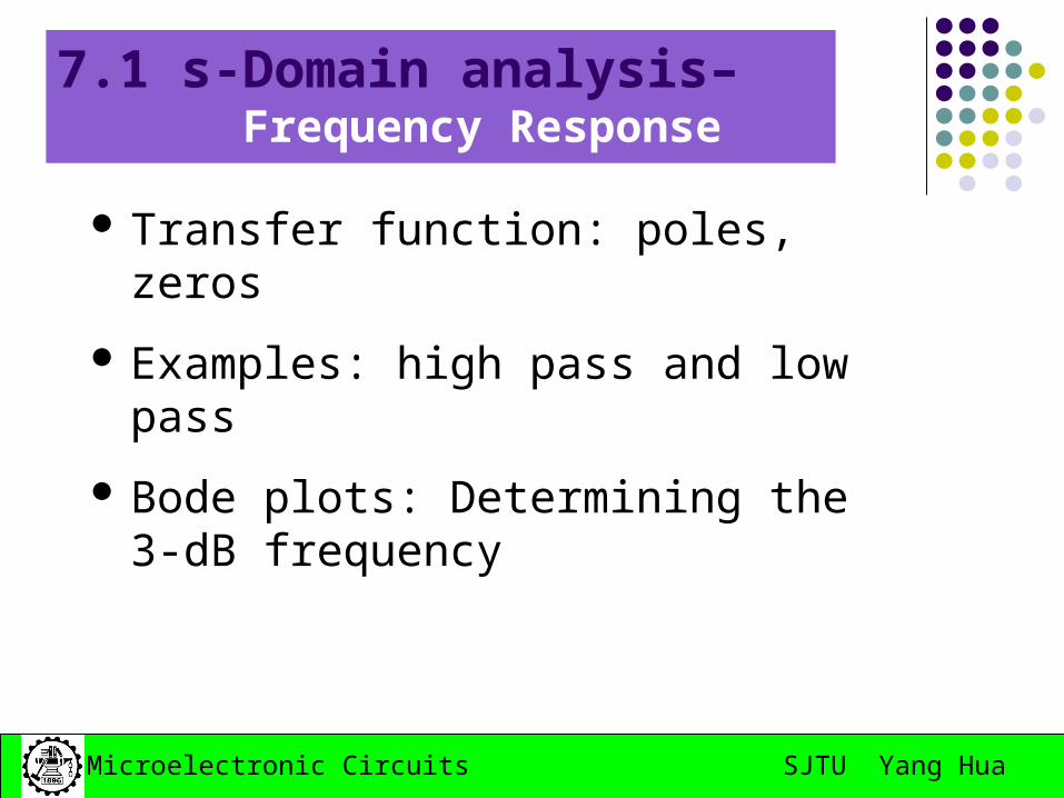
7.1 s-Domain analysis– Frequency Response
Transfer function: poles, zeros
Examples: high pass and low pass
Bode plots: Determining the 3-dB frequency
SJTU Yang HuaMicroelectronic Circuits
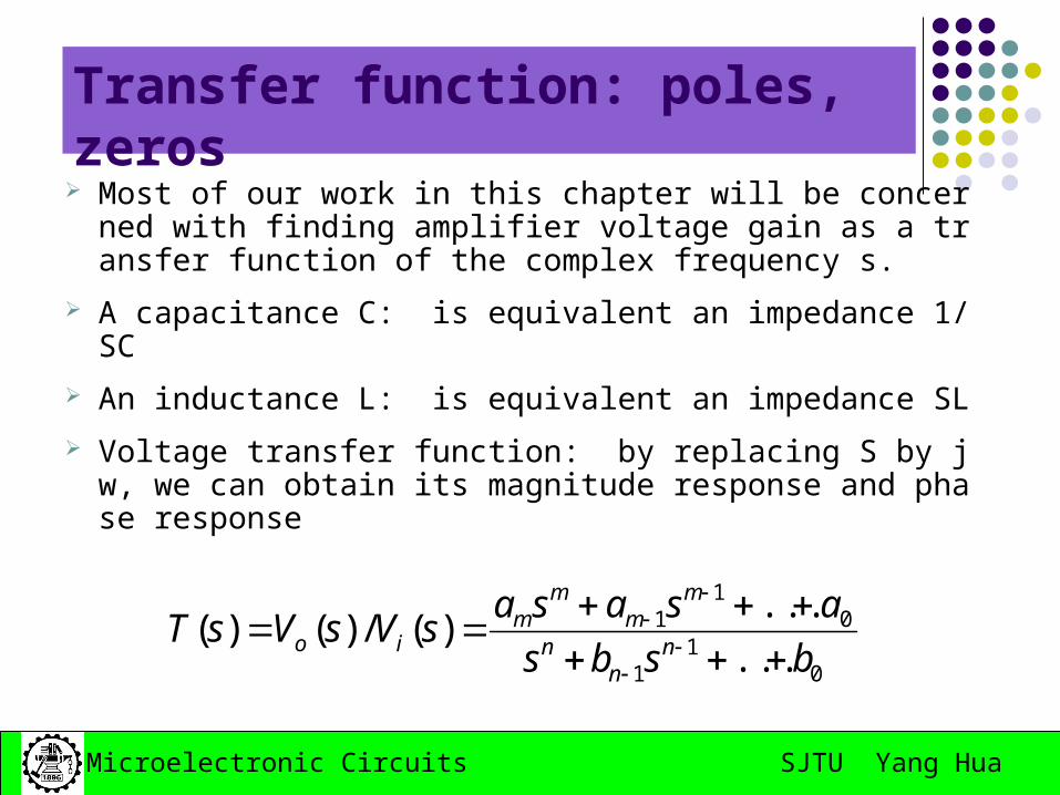
Transfer function: poles, zeros
Most of our work in this chapter will be concerned with finding amplifier voltage gain as a transfer function of the complex frequency s.
A capacitance C: is equivalent an impedance 1/SC
An inductance L: is equivalent an impedance SL
Voltage transfer function: by replacing S by jw, we can obtain its magnitude response and phase response
01
1
01
1
...
...)(/)()(
bsbs
asasasVsVsT
nn
n
mm
mm
io
SJTU Yang HuaMicroelectronic Circuits
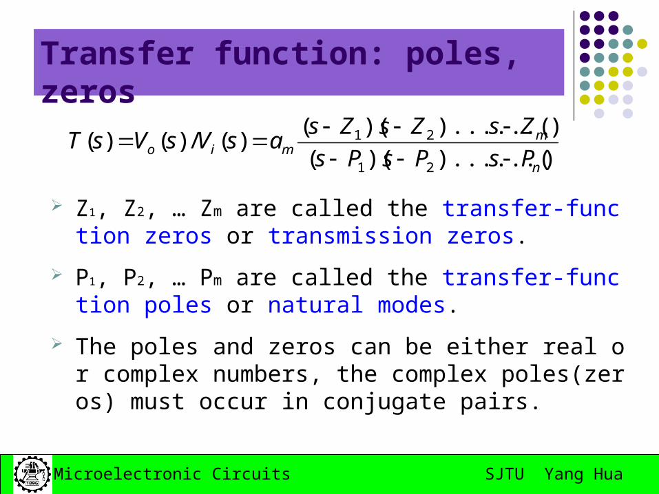
Transfer function: poles, zeros
Z1, Z2, … Zm are called the transfer-function zeros or transmission zeros.
P1, P2, … Pm are called the transfer-function poles or natural modes.
The poles and zeros can be either real or complex numbers, the complex poles(zeros) must occur in conjugate pairs.
))......()((
))......()(()(/)()(
21
21
n
mmio PsPsPs
ZsZsZsasVsVsT
SJTU Yang HuaMicroelectronic Circuits
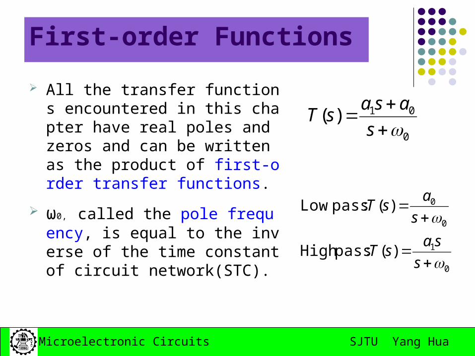
First-order Functions
All the transfer functions encountered in this chapter have real poles and zeros and can be written as the product of first-order transfer functions.
ω0, called the pole frequency, is equal to the inverse of the time constant of circuit network(STC).
0
01)(
s
asasT
0
1
0
0
)( :passHigh
)( :pass Low
s
sasT
s
asT
SJTU Yang HuaMicroelectronic Circuits
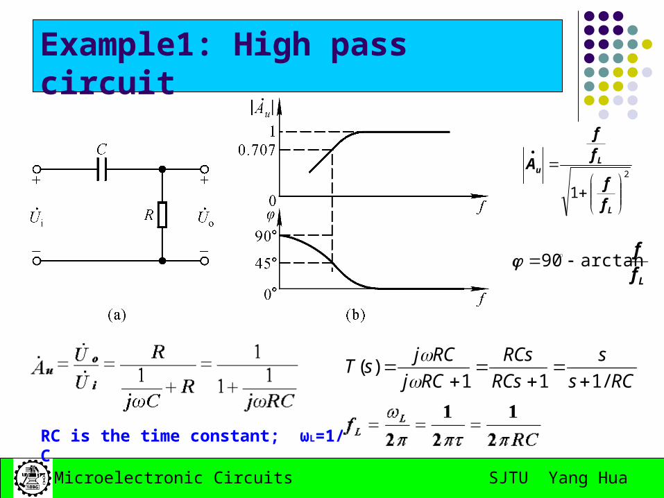
Example1: High pass circuit
2
1
L
Lu
f
f
f
f
A
RCs
s
RCs
RCs
RCj
RCjsT
/111)(
Lf
farctan90
RC is the time constant; ωL=1/RC
SJTU Yang HuaMicroelectronic Circuits
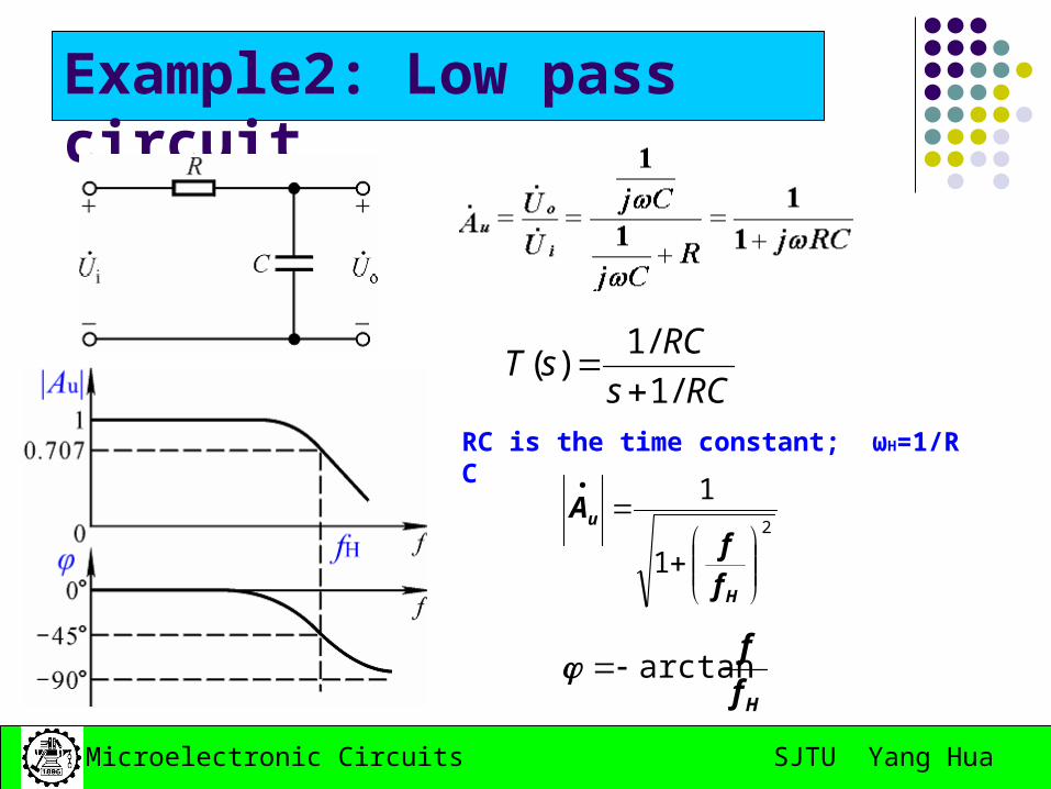
Example2: Low pass circuit
RCs
RCsT
/1
/1)(
Hf
farctan
RC is the time constant; ωH=1/RC
2
1
1
H
u
ff
A
SJTU Yang HuaMicroelectronic Circuits
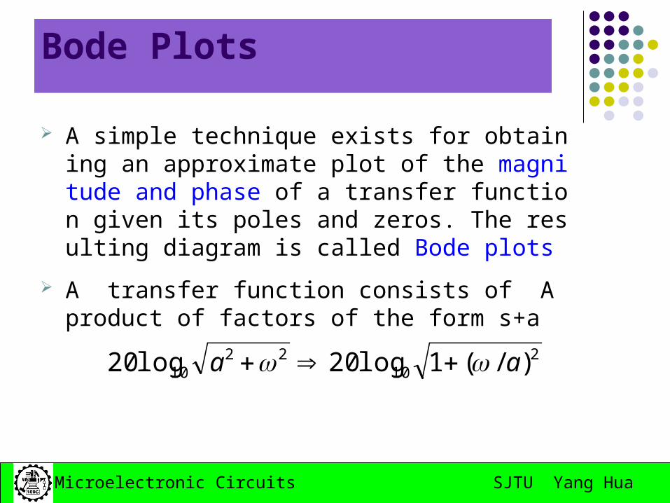
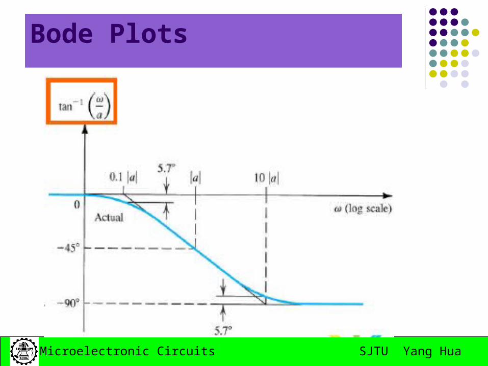
Bode Plots
A simple technique exists for obtaining an approximate plot of the magnitude and phase of a transfer function given its poles and zeros. The resulting diagram is called Bode plots
A transfer function consists of A product of factors of the form s+a
210
2210 )/(1log20log20 aa
SJTU Yang HuaMicroelectronic Circuits
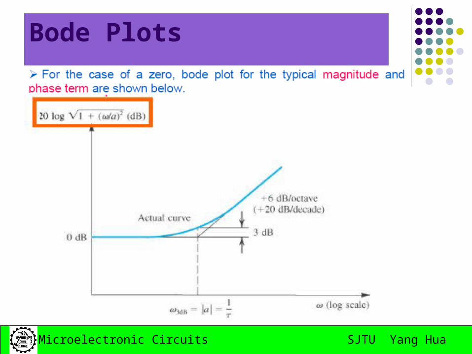
Bode Plots
SJTU Yang HuaMicroelectronic Circuits
Bode Plots
SJTU Yang HuaMicroelectronic Circuits
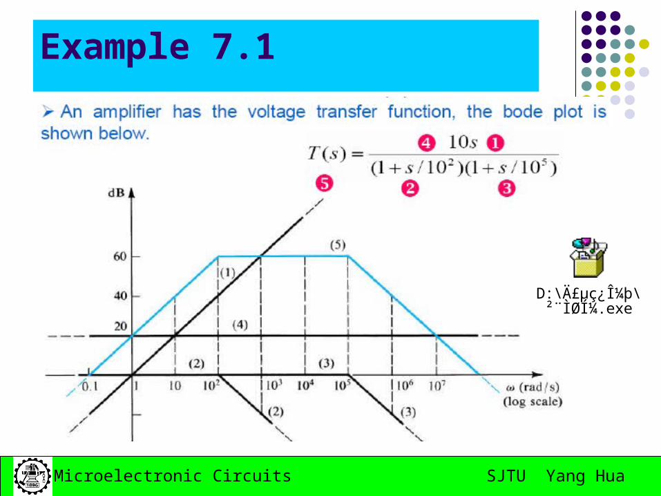
Example 7.1
D:\Ä£µç¿Î¼þ\²¨ÌØͼ.exe
SJTU Yang HuaMicroelectronic Circuits
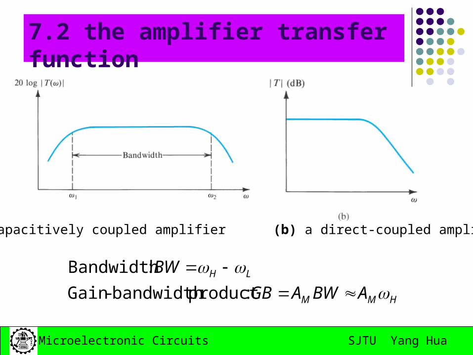
7.2 the amplifier transfer function
(a) a capacitively coupled amplifier (b) a direct-coupled amplifier
HMM
LH
ABWAGB
BW
:productbandwidth -Gain
:Bandwidth
SJTU Yang HuaMicroelectronic Circuits
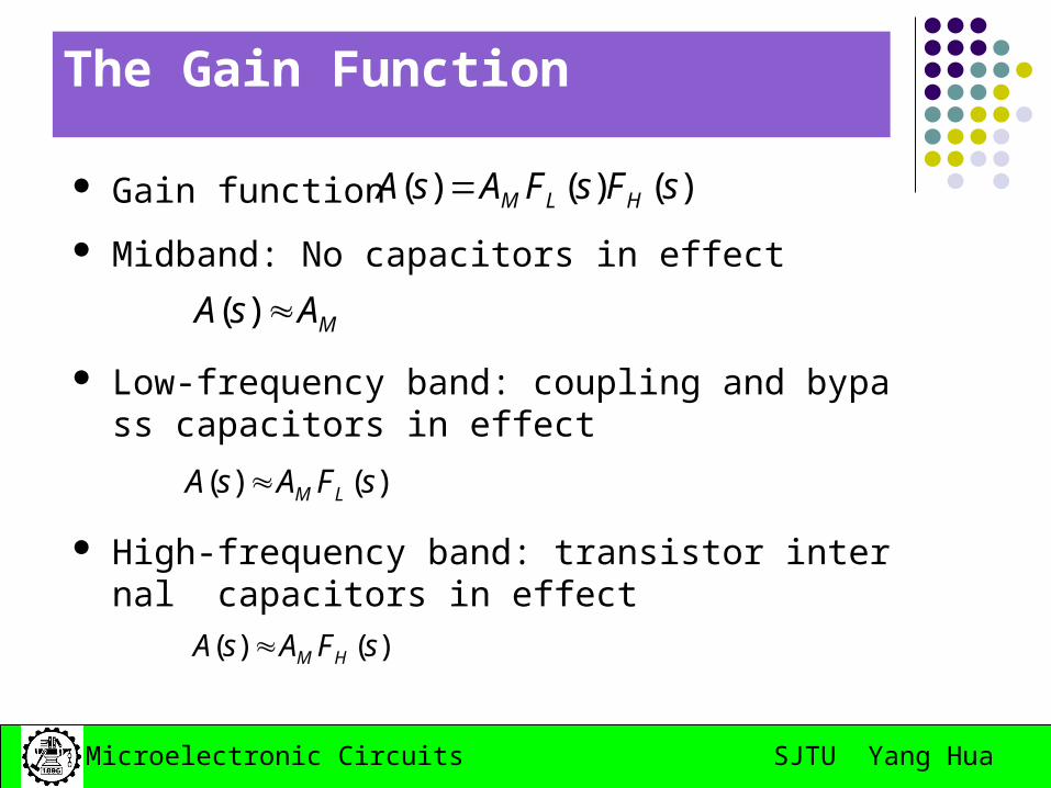
The Gain Function
Gain function
Midband: No capacitors in effect
Low-frequency band: coupling and bypass capacitors in effect
High-frequency band: transistor internal capacitors in effect
)()( sFAsA HM
)()()( sFsFAsA HLM
)()( sFAsA LM
MAsA )(
SJTU Yang HuaMicroelectronic Circuits
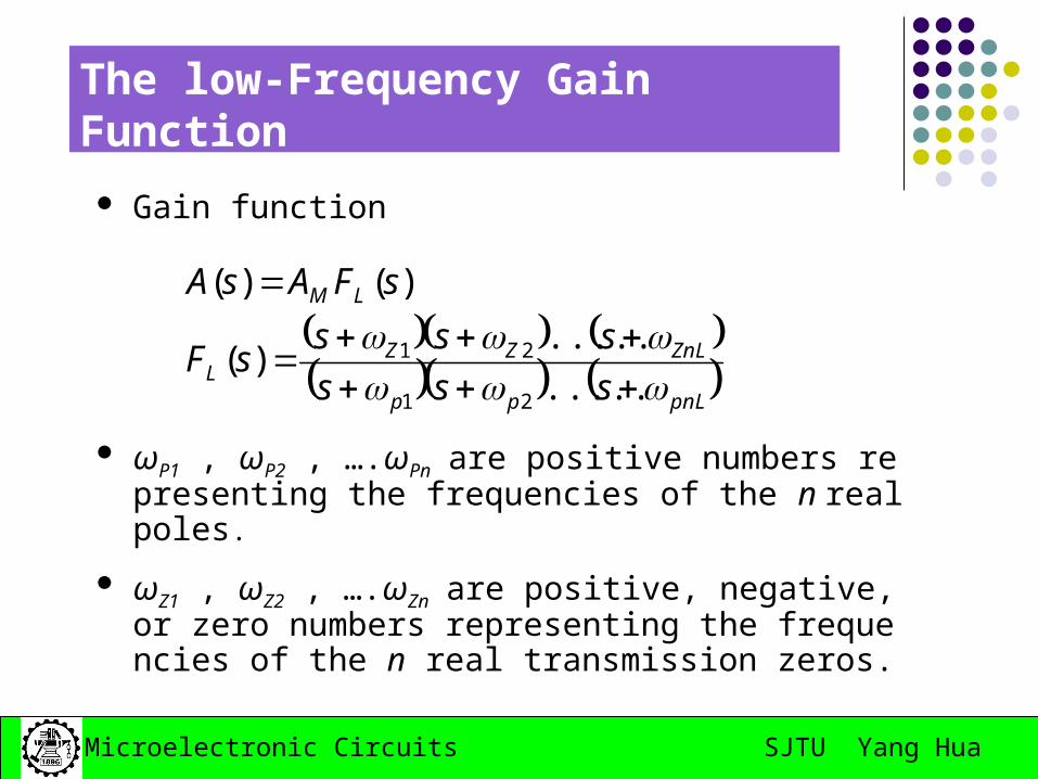
The low-Frequency Gain Function
Gain function
ωP1 , ωP2 , ….ωPn are positive numbers representing the frequencies of the n real poles.
ωZ1 , ωZ2 , ….ωZn are positive, negative, or zero numbers representing the frequencies of the n real transmission zeros.
pnLpp
ZnLZZL
LM
sss
ssssF
sFAsA
.....
.....)(
)()(
21
21
SJTU Yang HuaMicroelectronic Circuits
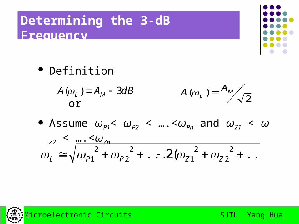
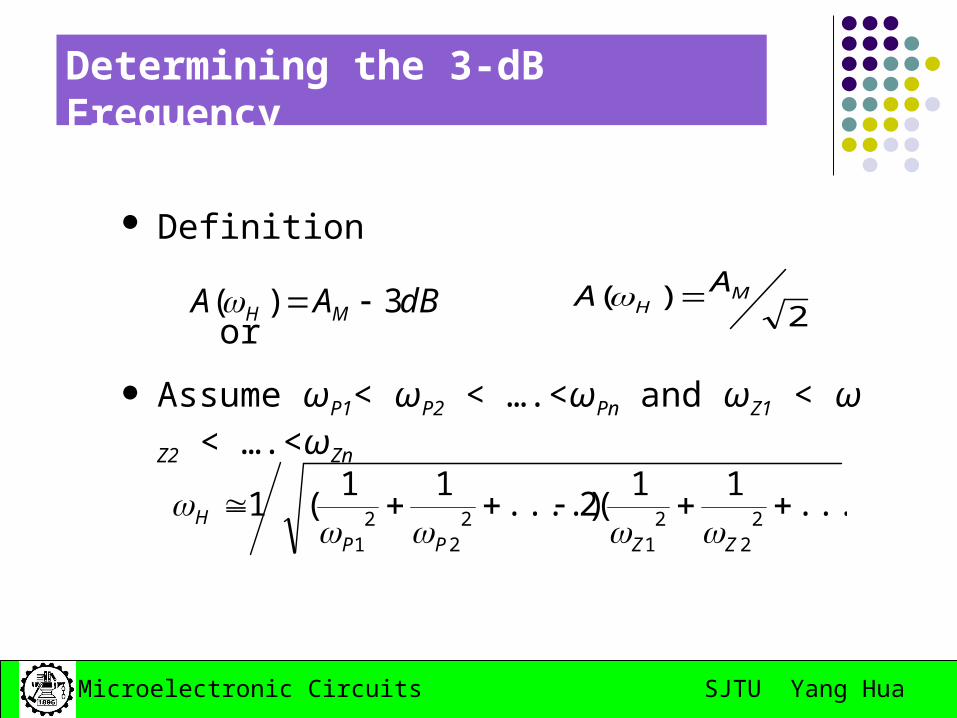
Determining the 3-dB Frequency
Definition
or
Assume ωP1< ωP2 < ….<ωPn and ωZ1 < ωZ2 < ….<ωZn
2)( M
LAA dBAA ML 3)(
...)(2... 22
21
22
21 ZZPPL
SJTU Yang HuaMicroelectronic Circuits
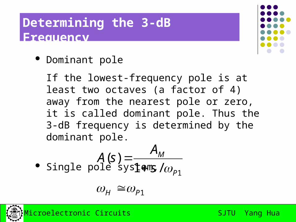
Determining the 3-dB Frequency
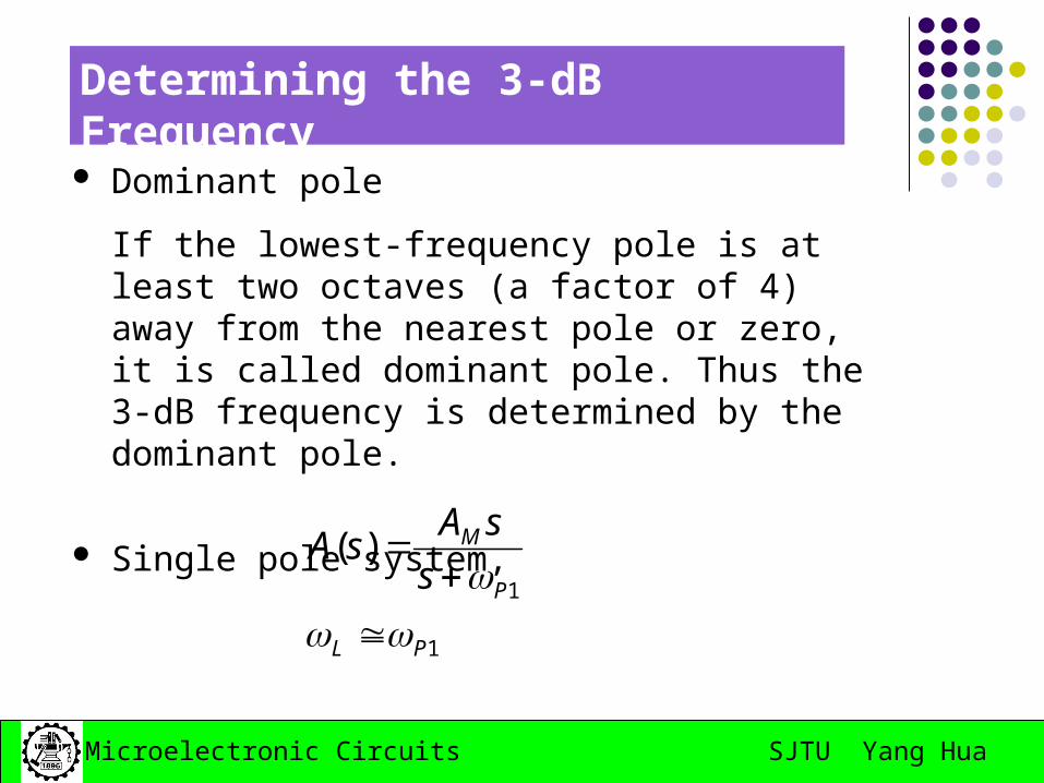
Dominant pole
If the lowest-frequency pole is at least two octaves (a factor of 4) away from the nearest pole or zero, it is called dominant pole. Thus the 3-dB frequency is determined by the dominant pole.
Single pole system,
1
1
)(
PL
P
M
s
sAsA
SJTU Yang HuaMicroelectronic Circuits
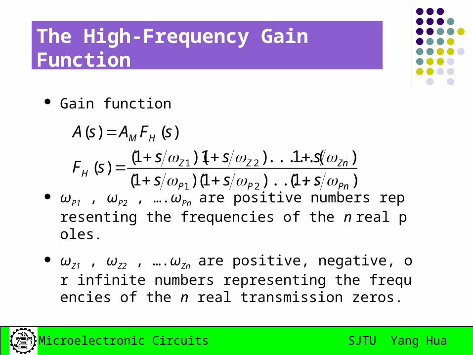
The High-Frequency Gain Function
Gain function
ωP1 , ωP2 , ….ωPn are positive numbers representing the frequencies of the n real poles.
ωZ1 , ωZ2 , ….ωZn are positive, negative, or infinite numbers representing the frequencies of the n real transmission zeros.
)1().....1()1(
)1.....()1)(1()(
)()(
21
21
PnPP
ZnZZH
HM
sss
ssssF
sFAsA
SJTU Yang HuaMicroelectronic Circuits
Determining the 3-dB Frequency
Definition
or
Assume ωP1< ωP2 < ….<ωPn and ωZ1 < ωZ2 < ….<ωZn
2)( M
HAA dBAA MH 3)(
....)11
(2....)11
(1 22
21
22
21
ZZPP
H
SJTU Yang HuaMicroelectronic Circuits
Determining the 3-dB Frequency
Dominant pole
If the lowest-frequency pole is at least two octaves (a factor of 4) away from the nearest pole or zero, it is called dominant pole. Thus the 3-dB frequency is determined by the dominant pole.
Single pole system,
1
1/1)(
PH
P
M
s
AsA
SJTU Yang HuaMicroelectronic Circuits
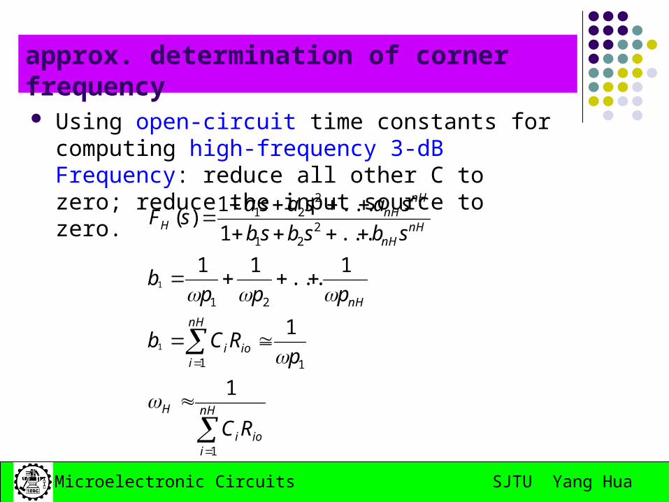
approx. determination of corner frequency
Using open-circuit time constants for computing high-frequency 3-dB Frequency: reduce all other C to zero; reduce the input source to zero.
nH
iioi
H
nH
iioi
nH
nHnH
nHnH
H
RC
pRCb
pppb
sbsbsb
sasasasF
1
11
21
221
221
1
1
1...
11
...1
...1)(
1
1
SJTU Yang HuaMicroelectronic Circuits
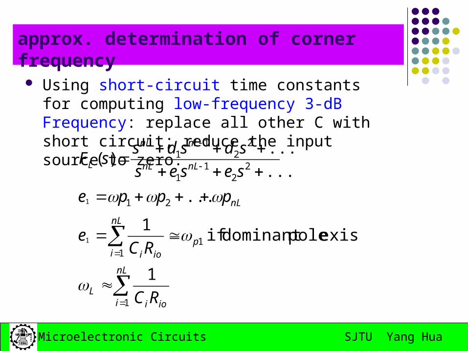
approx. determination of corner frequency
Using short-circuit time constants for computing low-frequency 3-dB Frequency: replace all other C with short circuit; reduce the input source to zero.
nL
i ioiL
p
nL
i ioi
nL
nLnL
nLnL
L
RC
RCe
pppe
seses
sdsdssF
1
11
21
22
11
22
11
1
exists poledominant if 1
...
...
...)(
1
1
SJTU Yang HuaMicroelectronic Circuits
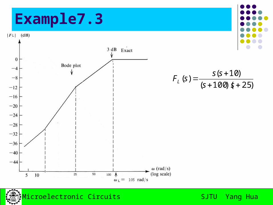
Example7.3
)25)(100(
)10()(
ss
sssFL
SJTU Yang HuaMicroelectronic Circuits
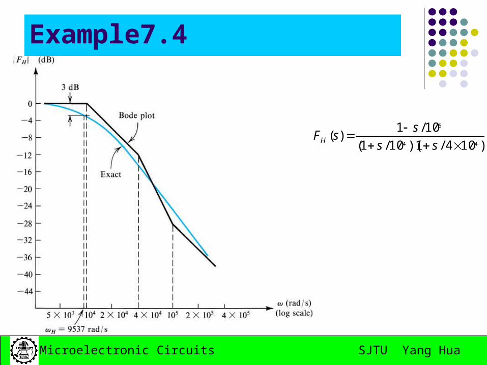
Example7.4
)104/1)(10/1(
10/1)(
44
5
ss
ssFH
SJTU Yang HuaMicroelectronic Circuits
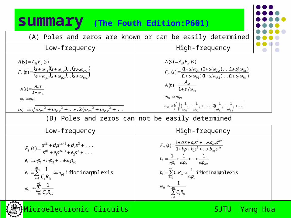
summary (The Fouth Edition:P601)
(A) Poles and zeros are known or can be easily determined
Low-frequency High-frequency
(B) Poles and zeros can not be easily determined
Low-frequency High-frequency
...)(2... 22
21
22
21 ZZPPL
1
1
)(
PL
P
M
s
sAsA
nH
iioi
H
nH
iioi
nH
nHnH
nHnH
H
RC
pRCb
pppb
sbsbsb
sasasasF
1
11
21
221
221
1
exists poledominant if 1
1...
11
...1
...1)(
1
1
nL
i ioiL
p
nL
i ioi
nL
nLnL
nLnL
L
RC
RCe
pppe
seses
sdsdssF
1
11
21
22
11
22
11
1
exists poledominant if 1
...
...
...)(
1
1
pnLpp
ZnLZZL
LM
sss
ssssF
sFAsA
.....
.....)(
)()(
21
21
)1().....1()1(
)1.....()1)(1()(
)()(
21
21
PnPP
ZnZZH
HM
sss
ssssF
sFAsA
1
1/1)(
PH
P
M
s
AsA
....)11
(2....)11
(1 22
21
22
21
ZZPP
H
SJTU Yang HuaMicroelectronic Circuits
Homework
April 17th, 2008
7.1; 7.2; 7.7; 7.10
SJTU Yang HuaMicroelectronic Circuits
Part II: Internal Capacitances of the BJT BJT High Frequency Model Internal Capacitances of the MOS MOS High Frequency Model Low-frequency of CS and CS amplifiers
SJTU Yang HuaMicroelectronic Circuits
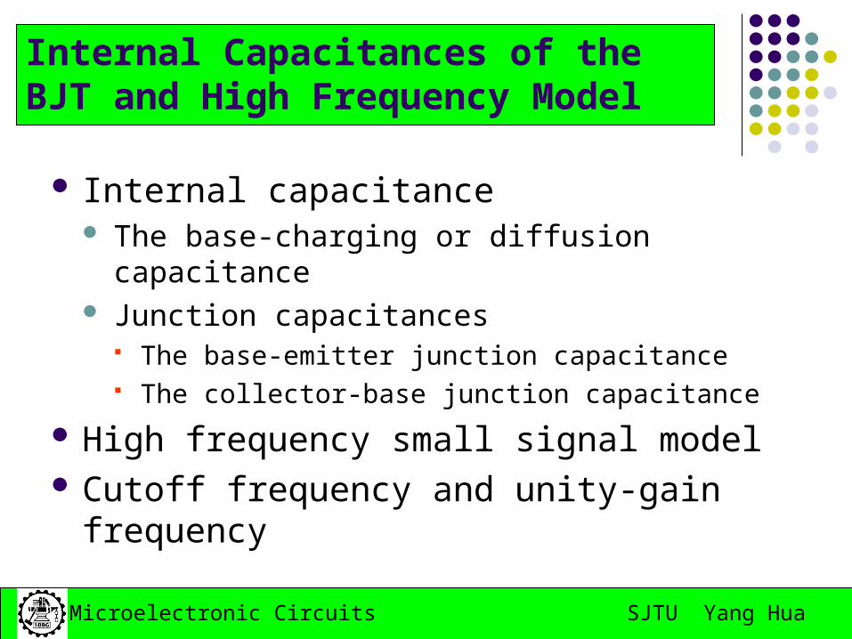
Internal capacitance The base-charging or diffusion capacitance Junction capacitances
The base-emitter junction capacitance The collector-base junction capacitance
High frequency small signal model Cutoff frequency and unity-gain frequency
Internal Capacitances of the BJT and High Frequency Model
SJTU Yang HuaMicroelectronic Circuits
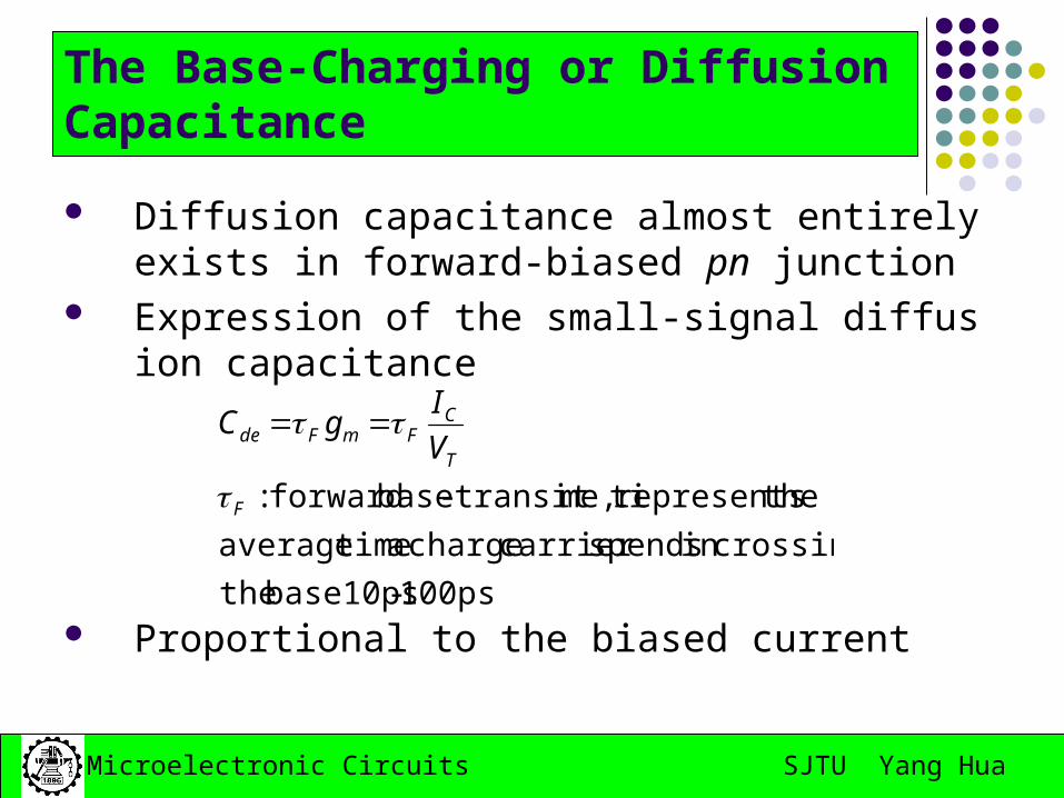
Diffusion capacitance almost entirely exists in forward-biased pn junction
Expression of the small-signal diffusion capacitance
Proportional to the biased current100ps-base10ps the
crossingin spendscarrier charge a timeaverage
therepresents me,transit ti-base forward:F
T
CFmFde V
IgC
The Base-Charging or Diffusion Capacitance
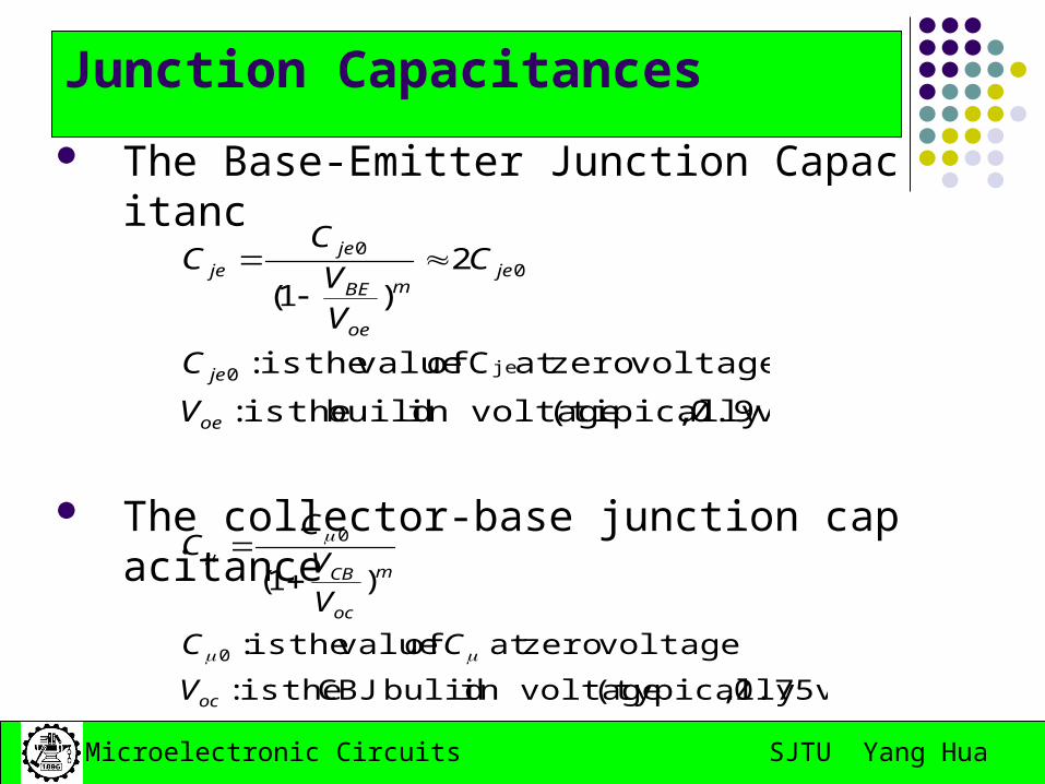
SJTU Yang HuaMicroelectronic Circuits
The Base-Emitter Junction Capacitanc
The collector-base junction capacitance
0.9v) ,(tipicallyin voltage build theis :
voltagezeroat C of value theis :
2)1(
je0
00
oe
je
jem
oe
BE
jeje
V
C
C
VV
CC
0.75v) ,(typicallyin voltage bulid CBJ theis :
voltagezeroat of value theis:
)1(
0
0
oc
m
oc
CB
V
CC
VV
CC
Junction Capacitances
SJTU Yang HuaMicroelectronic Circuits
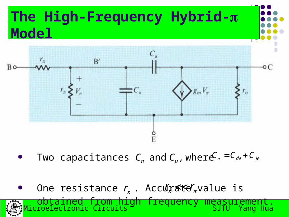
Two capacitances Cπ and Cμ , where
One resistance rx . Accurate value is obtained from high frequency measurement.
jede CCC
The High-Frequency Hybrid- Model
rrx
SJTU Yang HuaMicroelectronic Circuits
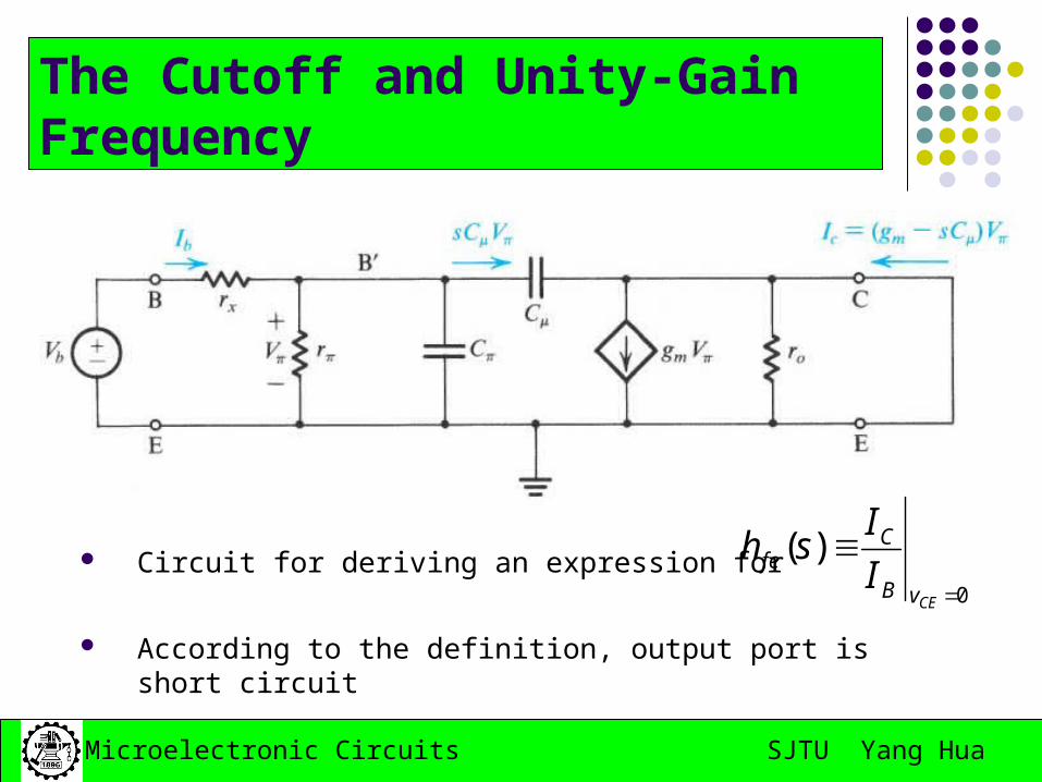
Circuit for deriving an expression for
According to the definition, output port is short circuit0
)(
CEvB
Cfe I
Ish
The Cutoff and Unity-Gain Frequency
SJTU Yang HuaMicroelectronic Circuits
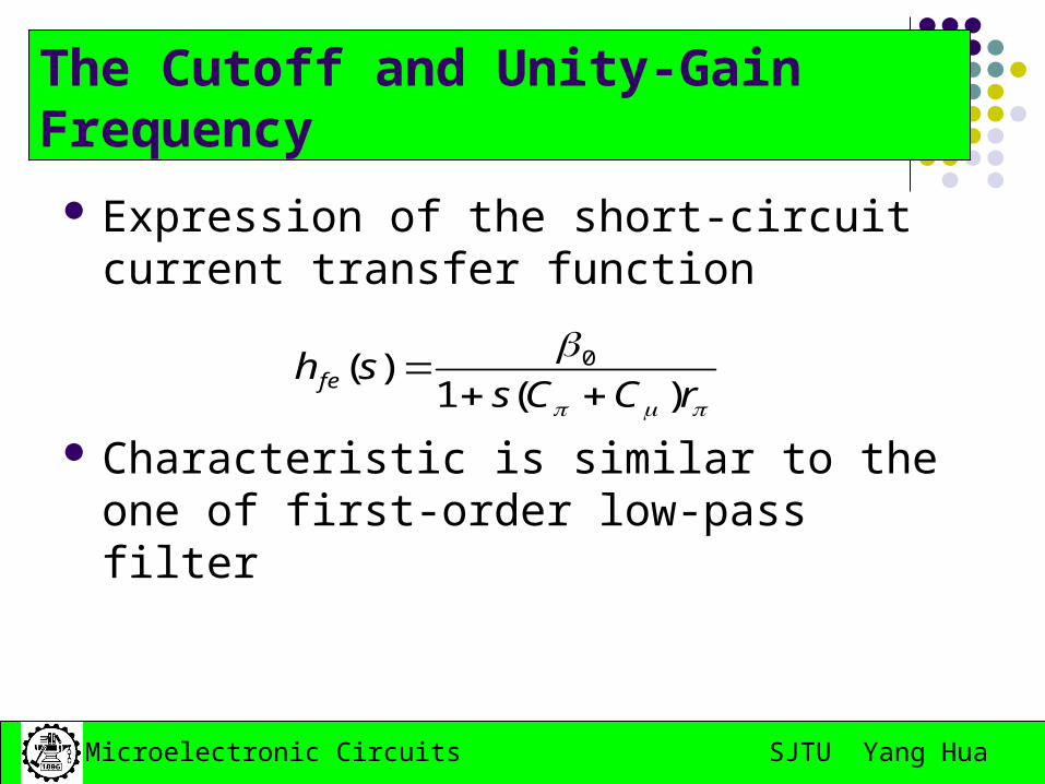
Expression of the short-circuit current transfer function
Characteristic is similar to the one of first-order low-pass filter
rCCs
sh fe )(1)( 0
The Cutoff and Unity-Gain Frequency
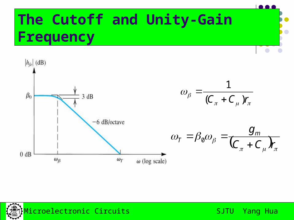
SJTU Yang HuaMicroelectronic Circuits
rCC )(
1
rCC
gmT
0
The Cutoff and Unity-Gain Frequency
SJTU Yang HuaMicroelectronic Circuits
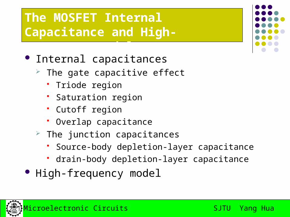
The MOSFET Internal Capacitance and High-Frequency Model
Internal capacitances The gate capacitive effect
Triode region Saturation region Cutoff region Overlap capacitance
The junction capacitances Source-body depletion-layer capacitance drain-body depletion-layer capacitance
High-frequency model
SJTU Yang HuaMicroelectronic Circuits
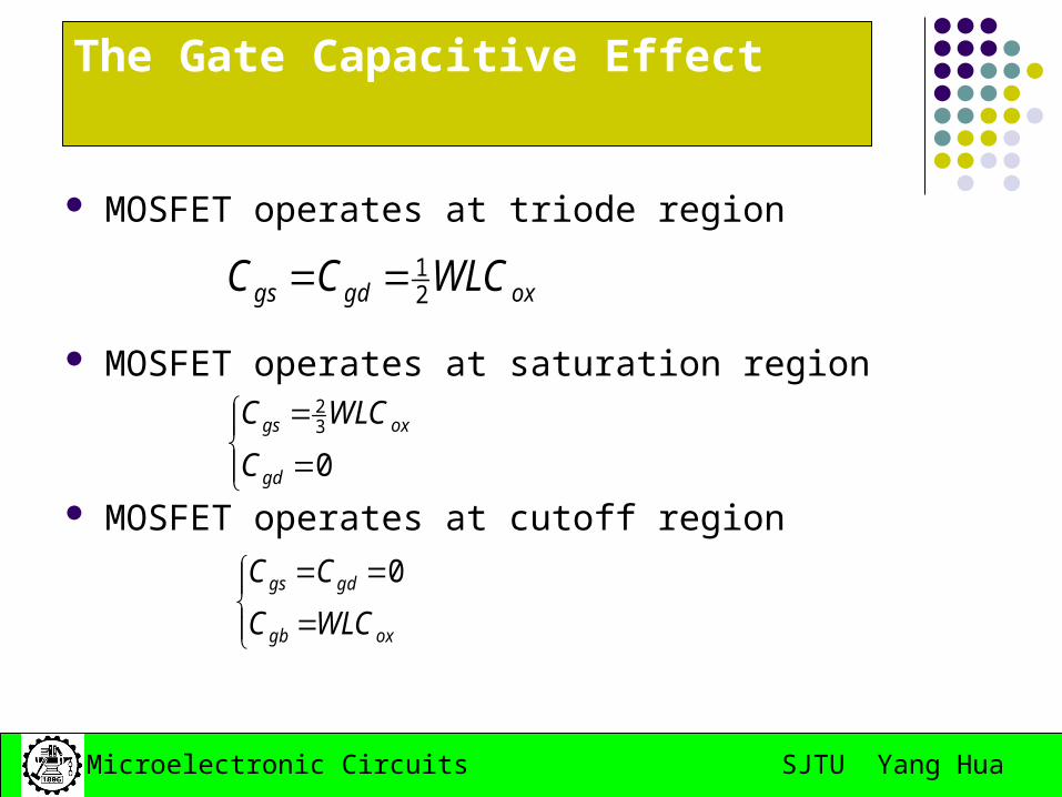
The Gate Capacitive Effect
MOSFET operates at triode region
MOSFET operates at saturation region
MOSFET operates at cutoff region
oxgdgs WLCCC 21
032
gd
oxgs
C
WLCC
oxgb
gdgs
WLCC
CC 0
SJTU Yang HuaMicroelectronic Circuits
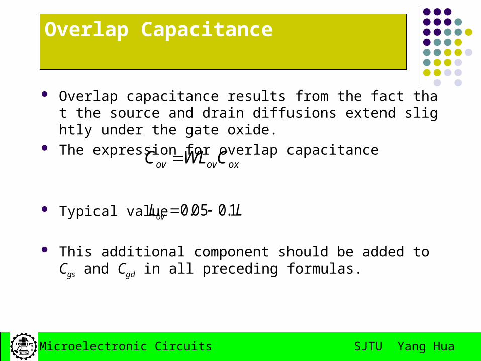
Overlap Capacitance
Overlap capacitance results from the fact that the source and drain diffusions extend slightly under the gate oxide.
The expression for overlap capacitance
Typical value
This additional component should be added to Cgs and Cgd in all preceding formulas.
oxovov CWLC
LLov 1.005.0
SJTU Yang HuaMicroelectronic Circuits
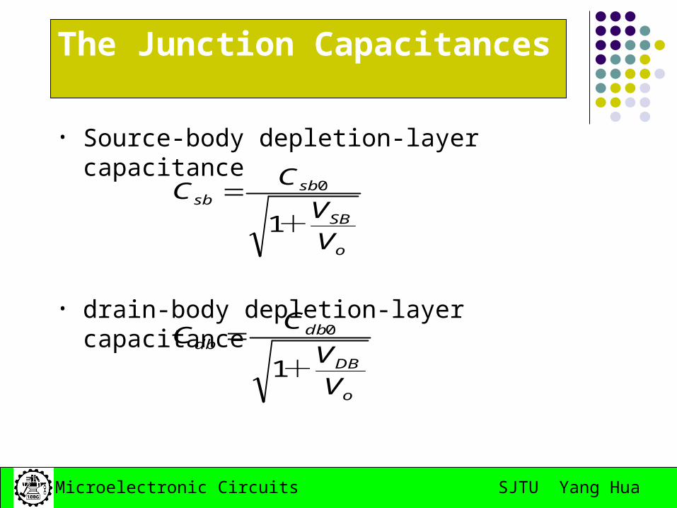
The Junction Capacitances
• Source-body depletion-layer capacitance
• drain-body depletion-layer capacitanceo
SB
sbsb
V
V
CC
+1
0
o
DB
dbdb
VV
CC
+1
0
SJTU Yang HuaMicroelectronic Circuits
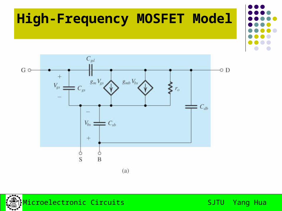
High-Frequency MOSFET Model
SJTU Yang HuaMicroelectronic Circuits
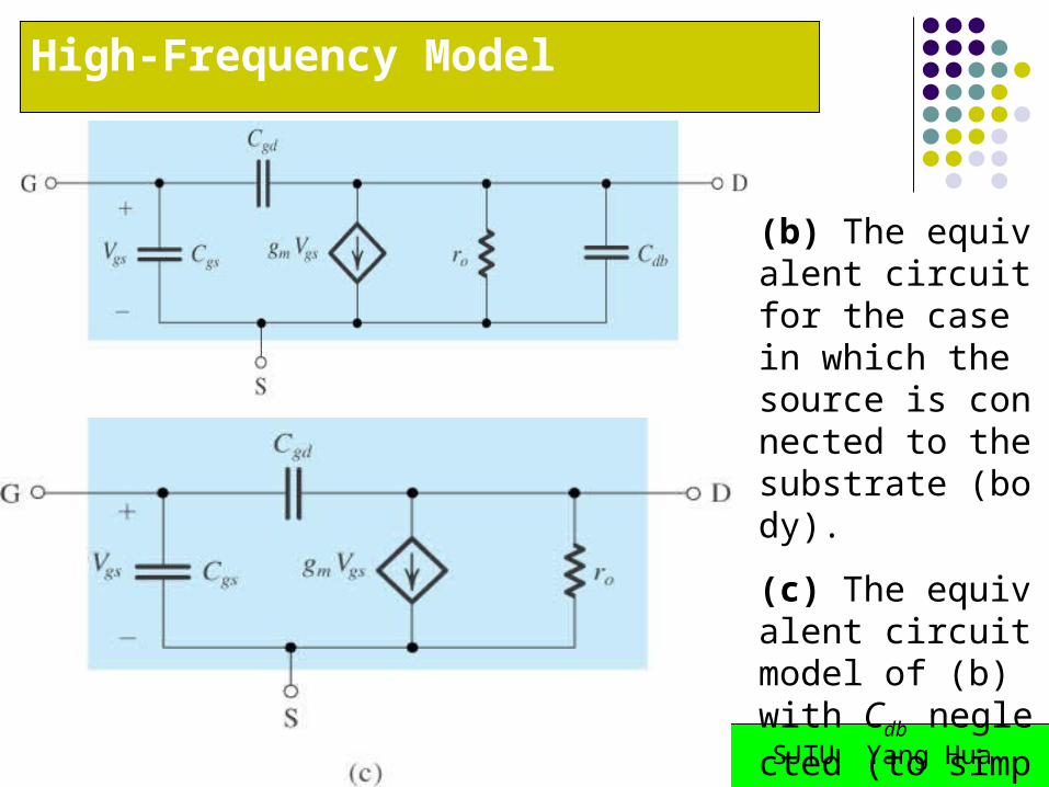
High-Frequency Model
(b) The equivalent circuit for the case in which the source is connected to the substrate (body).
(c) The equivalent circuit model of (b) with Cdb neglected (to simplify analysis).
SJTU Yang HuaMicroelectronic Circuits
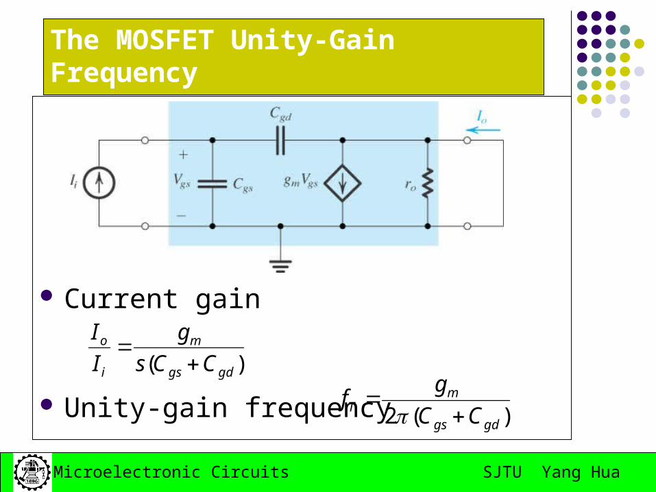
The MOSFET Unity-Gain Frequency
Current gain
Unity-gain frequency
)( gdgs
m
i
o
CCs
g
I
I
)(2 gdgs
mT CC
gf
SJTU Yang HuaMicroelectronic Circuits
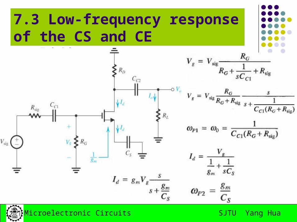
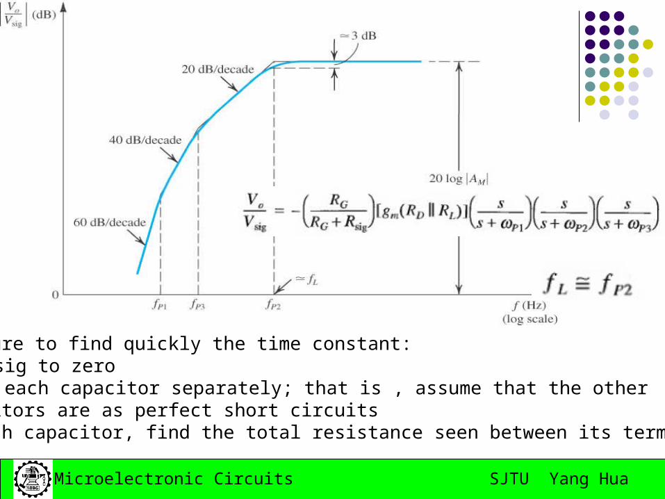
7.3 Low-frequency response of the CS and CE amplifiers
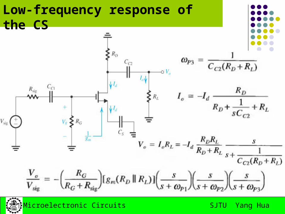
SJTU Yang HuaMicroelectronic Circuits
Low-frequency response of the CS
SJTU Yang HuaMicroelectronic Circuits
The procedure to find quickly the time constant:1. Reduce Vsig to zero2. Consider each capacitor separately; that is , assume that the other Capacitors are as perfect short circuits3. For each capacitor, find the total resistance seen between its terminals
SJTU Yang HuaMicroelectronic Circuits
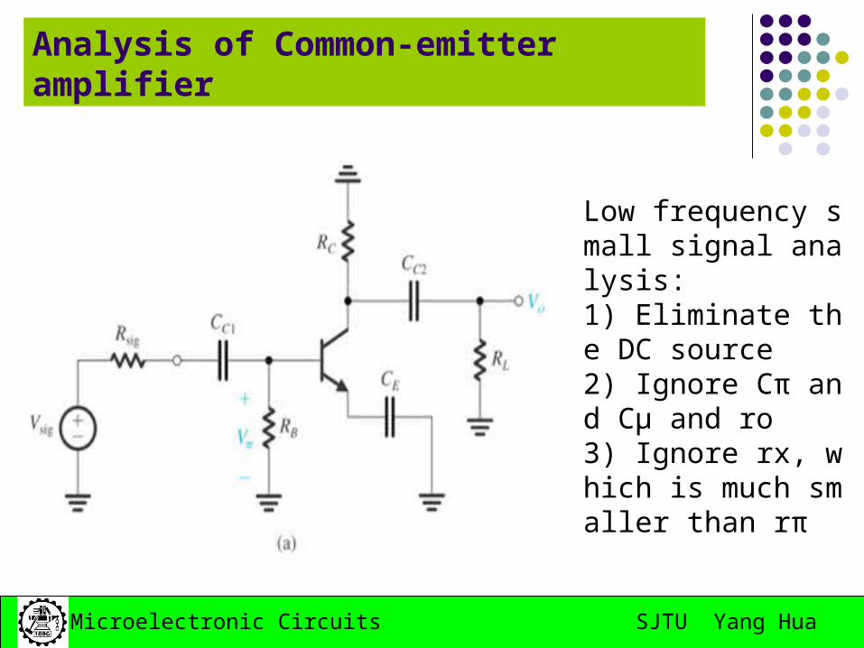
Analysis of Common-emitter amplifier
Low frequency small signal analysis:1) Eliminate the DC source2) Ignore Cπ and Cμ and ro3) Ignore rx, which is much smaller than rπ
SJTU Yang HuaMicroelectronic Circuits
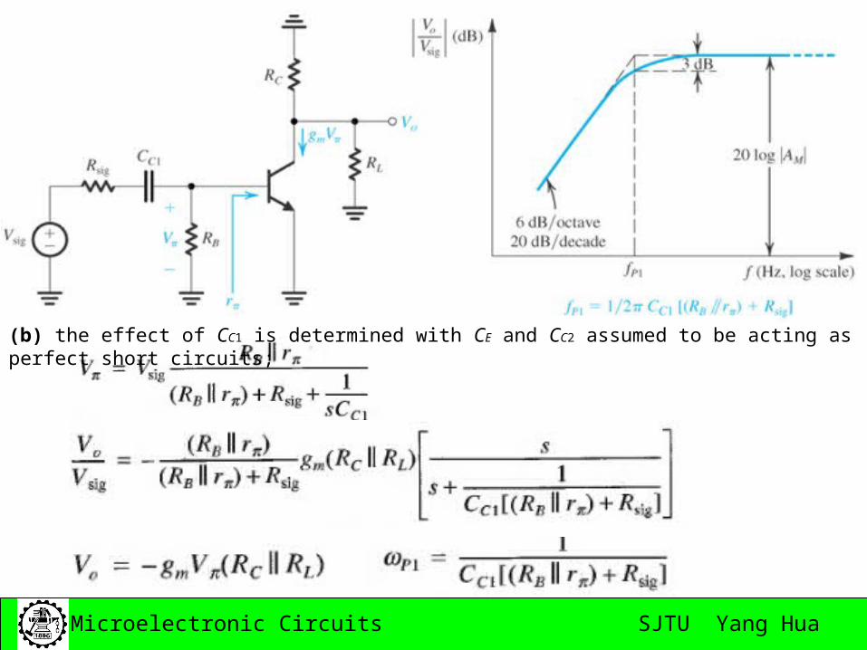
(b) the effect of CC1 is determined with CE and CC2 assumed to be acting as perfect short circuits;
SJTU Yang HuaMicroelectronic Circuits
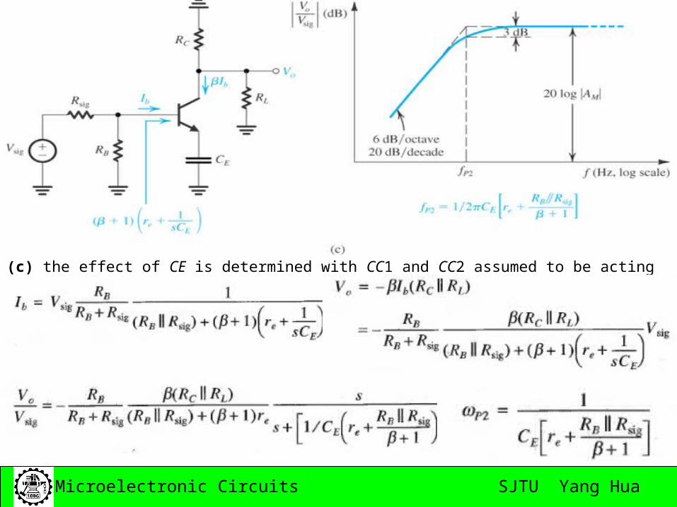
(c) the effect of CE is determined with CC1 and CC2 assumed to be acting as perfect short circuits
SJTU Yang HuaMicroelectronic Circuits
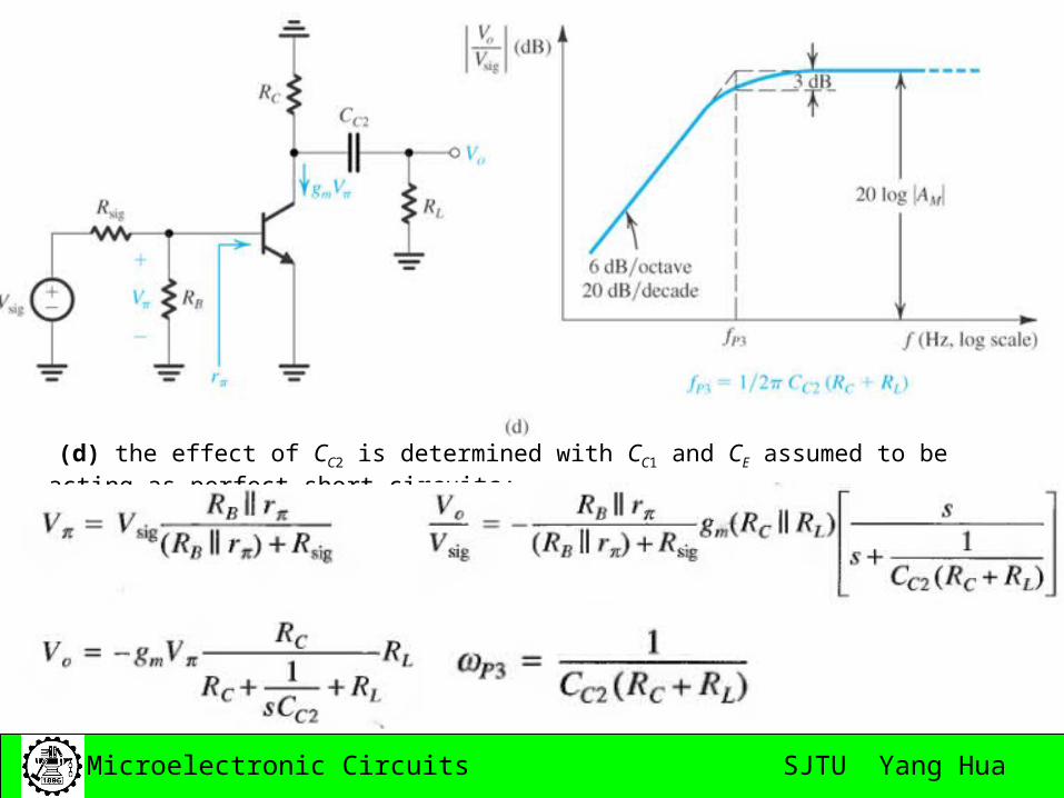
(d) the effect of CC2 is determined with CC1 and CE assumed to be acting as perfect short circuits;
SJTU Yang HuaMicroelectronic Circuits
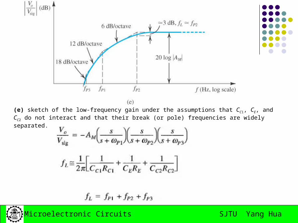
(e) sketch of the low-frequency gain under the assumptions that CC1, CE, and CC2 do not interact and that their break (or pole) frequencies are widely separated.
SJTU Yang HuaMicroelectronic Circuits
Homework:
April 15th, 2008
7.29; 7.35; 7.39
SJTU Yang HuaMicroelectronic Circuits
7.4 High-frequency response of the CS and CE amplifiers
• Miller’s theorem.
• Analysis of the high frequency response.
Using Miller’s theorem.
Using open-circuit time constants.
SJTU Yang HuaMicroelectronic Circuits
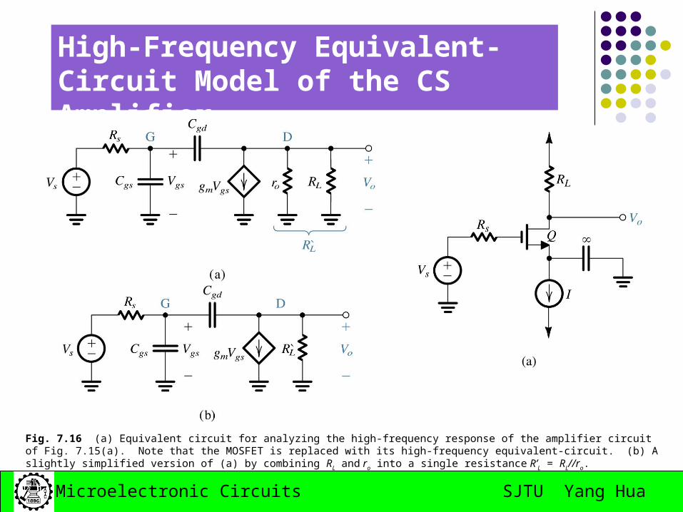
High-Frequency Equivalent-Circuit Model of the CS Amplifier
Fig. 7.16 (a) Equivalent circuit for analyzing the high-frequency response of the amplifier circuit of Fig. 7.15(a). Note that the MOSFET is replaced with its high-frequency equivalent-circuit. (b) A slightly simplified version of (a) by combining RL and ro into a single resistance R’L = RL//ro.
SJTU Yang HuaMicroelectronic Circuits
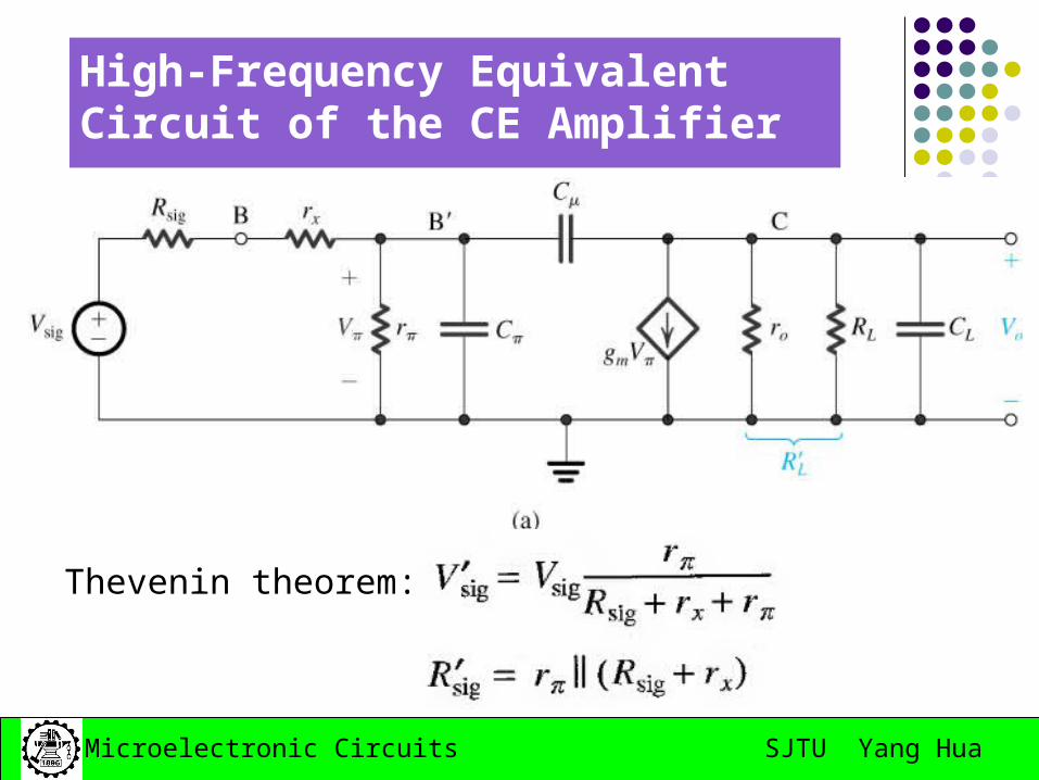
High-Frequency Equivalent-Circuit Model of the CE Amplifier
Fig. . 7.17 (a) Equivalent circuit for the analysis of the high-frequency response of the common-emitter amplifier of Fig. 7.15(b). Note that the BJT is replaced with its hybrid- high-frequency equivalent circuit. (b) An equivalent but simpler version of the circuit in (a),
oLL
xss
ssss
rRR
rrRR
rrR
rVV
//
// '
'
'
SJTU Yang HuaMicroelectronic Circuits
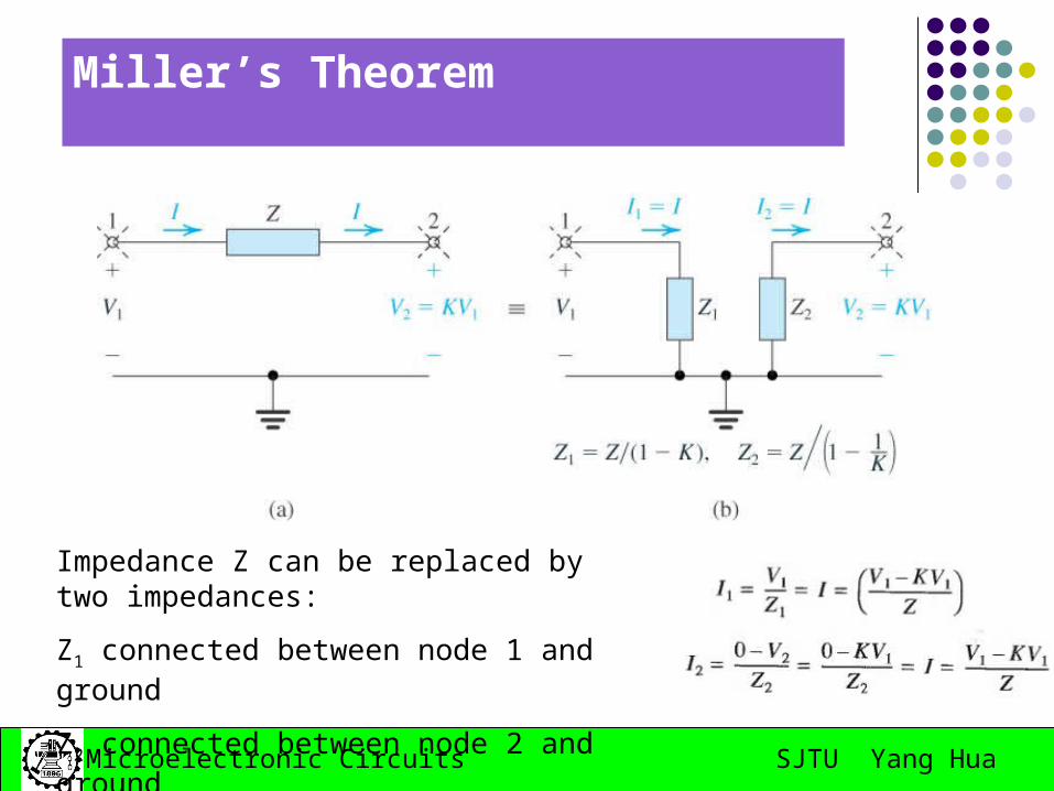
Miller’s Theorem
Impedance Z can be replaced by two impedances:
Z1 connected between node 1 and ground
Z2 connected between node 2 and ground
SJTU Yang HuaMicroelectronic Circuits
Miller’s Theorem
The miller equivalent circuit is valid as long as the conditions that existed in the network when K was determined are not changed.
Miller theorem can be used to determining the input impedance and the gain of an amplifier; it cannot be applied to determine the output impedance.
SJTU Yang HuaMicroelectronic Circuits
Analysis Using Miller’s Theorem
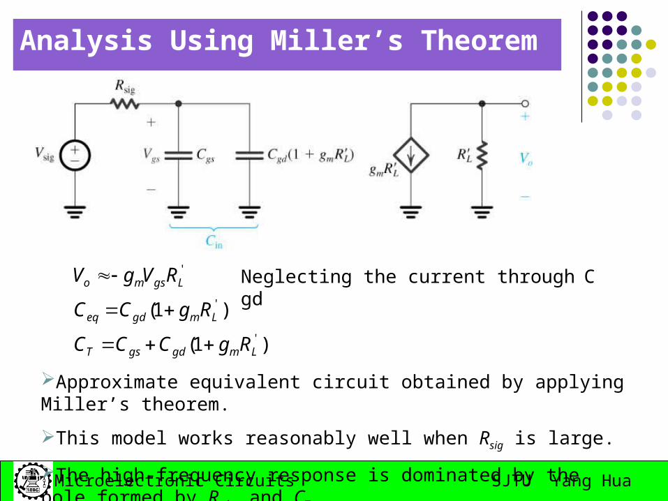
Approximate equivalent circuit obtained by applying Miller’s theorem.
This model works reasonably well when Rsig is large.
The high-frequency response is dominated by the pole formed by Rsig and CT.
)1(
)1('
'
'
LmgdgsT
Lmgdeq
Lgsmo
RgCCC
RgCC
RVgV
Neglecting the current through Cgd
SJTU Yang HuaMicroelectronic Circuits
Analysis Using Miller’s Theorem
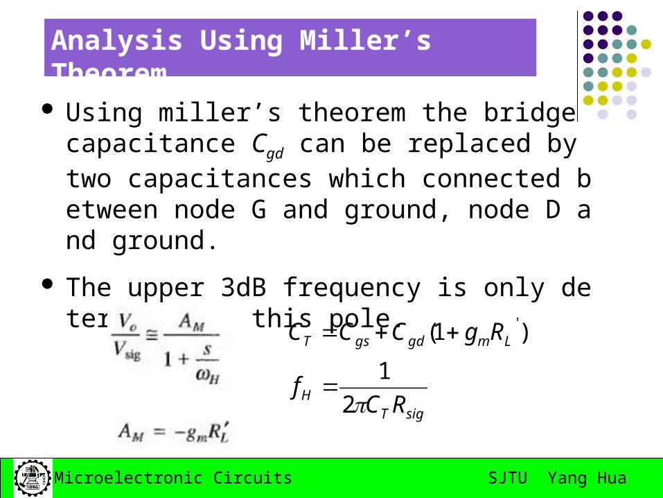
Using miller’s theorem the bridge capacitance Cgd can be replaced by two capacitances which connected between node G and ground, node D and ground.
The upper 3dB frequency is only determined by this pole.
sigTH
LmgdgsT
RCf
RgCCC
2
1
)1( '
SJTU Yang HuaMicroelectronic Circuits
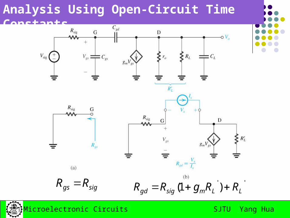
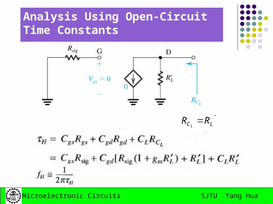
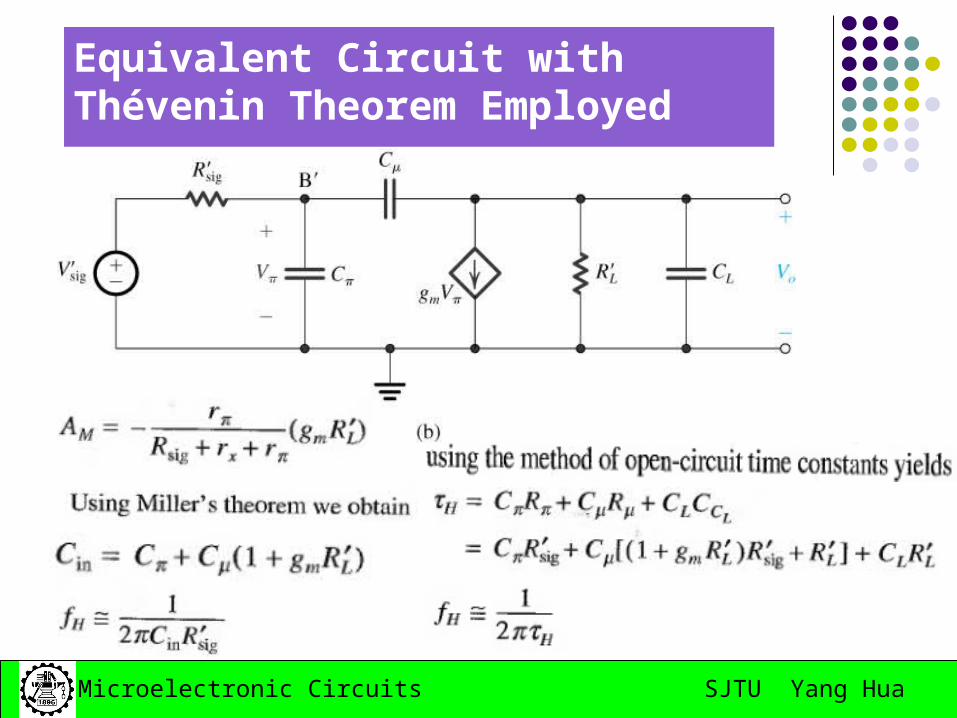
Analysis Using Open-Circuit Time Constants
siggs RR '')1( LLmsiggd RRgRR
SJTU Yang HuaMicroelectronic Circuits
Analysis Using Open-Circuit Time Constants
'LC RR
L
SJTU Yang HuaMicroelectronic Circuits
High-Frequency Equivalent Circuit of the CE Amplifier
Thevenin theorem:
SJTU Yang HuaMicroelectronic Circuits
Equivalent Circuit with Thévenin Theorem Employed
SJTU Yang HuaMicroelectronic Circuits
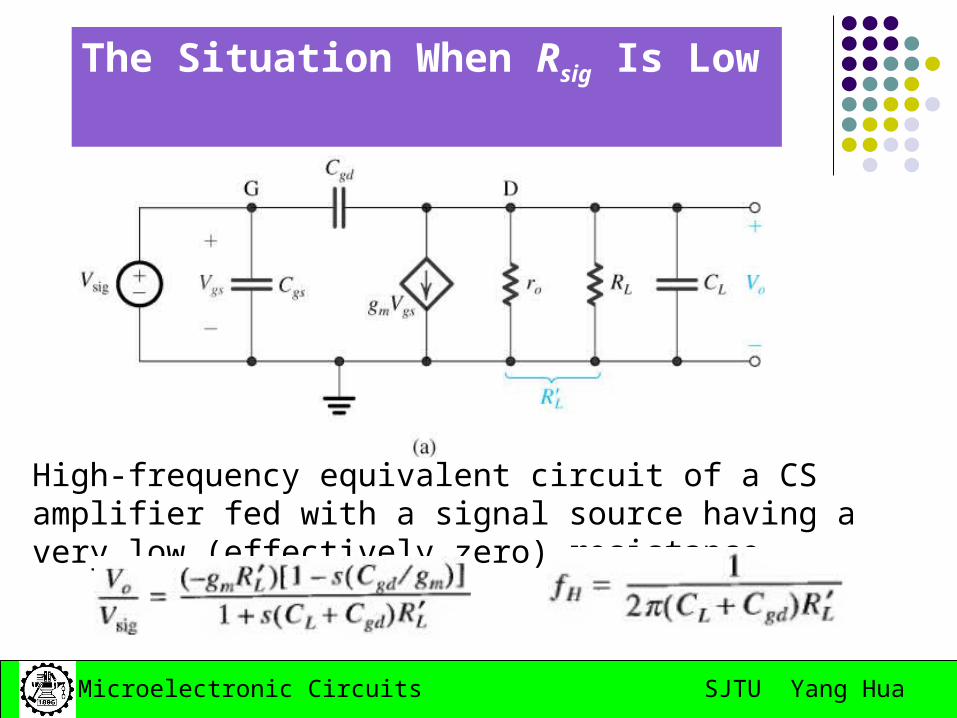
The Situation When Rsig Is Low
High-frequency equivalent circuit of a CS amplifier fed with a signal source having a very low (effectively zero) resistance.
SJTU Yang HuaMicroelectronic Circuits
The Situation When Rsig Is Low
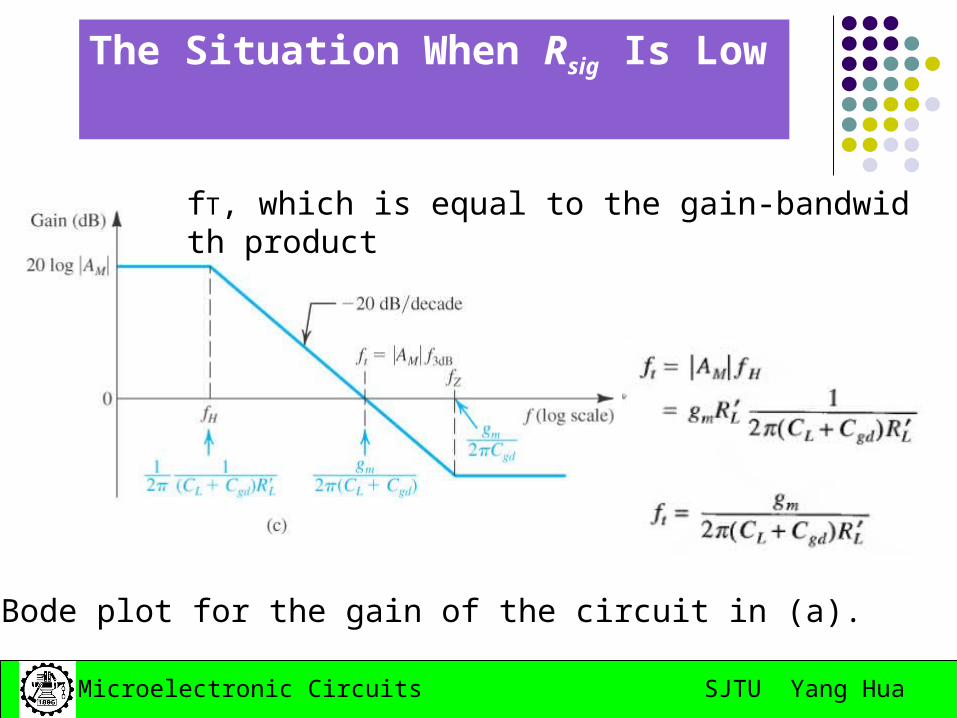
Bode plot for the gain of the circuit in (a).
fT, which is equal to the gain-bandwidth product
SJTU Yang HuaMicroelectronic Circuits
The Situation When Rsig Is Low
The high frequency gain will no longer be limited by the interaction of the source resistance and the input capacitance.
The high frequency limitation happens at the amplifier output.
To improve the 3-dB frequency, we shall reduce the equivalent resistance seen through G(B) and D(C) terminals.
SJTU Yang HuaMicroelectronic Circuits
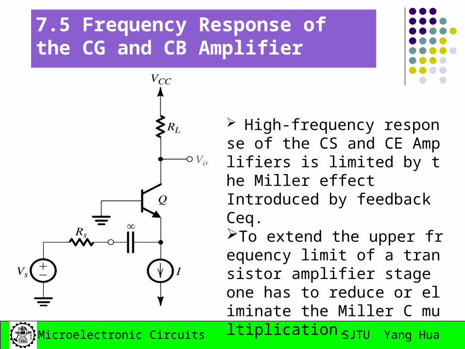
7.5 Frequency Response of the CG and CB Amplifier
High-frequency response of the CS and CE Amplifiers is limited by the Miller effect Introduced by feedback Ceq.To extend the upper frequency limit of a transistor amplifier stage one has to reduce or eliminate the Miller C multiplication.
SJTU Yang HuaMicroelectronic Circuits
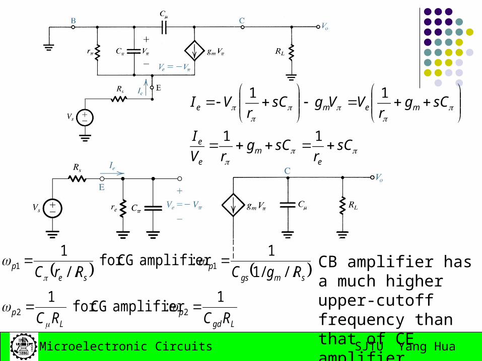
sCr
sCgrV
I
sCgr
VVgsCr
VI
em
e
e
meme
11
11
Lgdp
Lp
smgsp
sep
RCRC
RgCRrC
1:amplifierCG for
1
///1
1 :amplifierCG for
//
1
22
11
CB amplifier has a much higher upper-cutoff frequency than that of CE amplifier
SJTU Yang HuaMicroelectronic Circuits
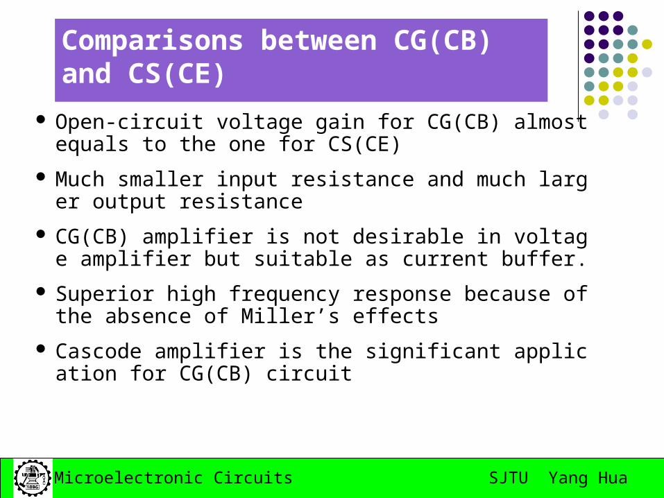
Comparisons between CG(CB) and CS(CE)
Open-circuit voltage gain for CG(CB) almost equals to the one for CS(CE)
Much smaller input resistance and much larger output resistance
CG(CB) amplifier is not desirable in voltage amplifier but suitable as current buffer.
Superior high frequency response because of the absence of Miller’s effects
Cascode amplifier is the significant application for CG(CB) circuit
SJTU Yang HuaMicroelectronic Circuits
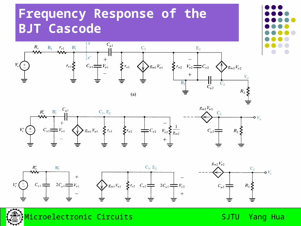
Frequency Response of the BJT Cascode
SJTU Yang HuaMicroelectronic Circuits
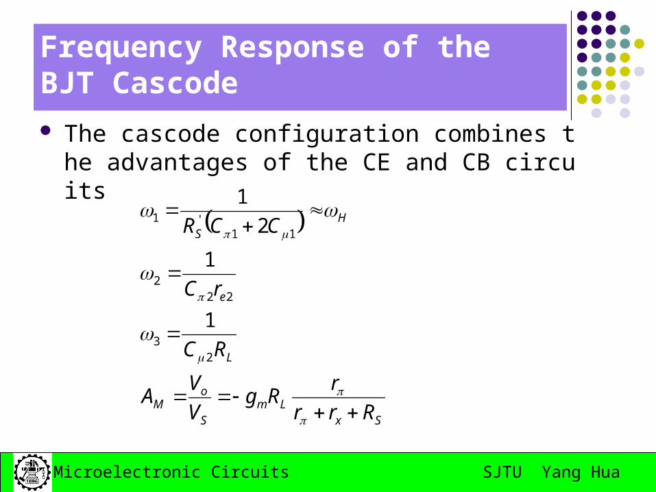
Frequency Response of the BJT Cascode
The cascode configuration combines the advantages of the CE and CB circuits
SxLm
S
oM
L
e
HS
Rrr
rRg
V
VA
RC
rC
CCR
23
222
11'1
1
1
2
1
SJTU Yang HuaMicroelectronic Circuits
The Source (Emitter) Follower
• Self-study• Read the textbook from pp626-629
SJTU Yang HuaMicroelectronic Circuits
Homework:
May 6th,2008
7.44; 7.45; 7.46; 7.57
SJTU Yang HuaMicroelectronic Circuits
Test: ( 1 ) the reason for gain decreasing of high-frequency respons
e , the reason for gain decreasing of low-frequency response 。
A. coupling capacitors and bypass capacitors B. diffusion capacitors and junction capacitors C. linear characteristics of semiconductors D. the quiescent point is not proper ( 2 ) when signal frequency is equal to fL or fH , the gain of of
amplifier decreases compare to that of midband frequency 。 A.0.5times B.0.7times C.0.9times that is decreasing 。 A.3dB B.4dB C.5dB ( 3 ) The CE amplifier circuit , when f = fL , the phase is 。 A. + 45˚ B. - 90˚ C. - 135˚ when f = fH , the phase is 。 A. - 45˚ B. - 135˚ C. - 225˚