Embed Size (px)
Citation preview
MicroCorean Open-Source, Scalable,
Dual-Stack, Harvard Processor
Synthesisable VHDL for FPGAs
Introduction
Using an FPGA based simple and extensible processor core as the foundation of a system eventuallyfrees the programmer from the limitations of any static processor architecture, be it CISC, RISC,WISC, FRISC or otherwise. No more programming around known hardware bugs. A choice can bemade as to whether a needed functionality should be implemented in hardware or software. Simply,the least complex, most energy efficient solution can be realised while working on a specificapplication. Of course, using FPGAs is a hefty blow for MIPS ratings. But, building on an FPGA,time critical and perhaps complex functions can be realised in hardware in exactly the way neededby the application, offloading the processor from sub-optimal inner software loops.
The FPGA approach also makes the user independent from product discontinuity problems thathaunt the hi-rel industry since the dawn of the silicon age. Finally: putting the core into FPGAs putsan end to one of the high-level programming language paradigms, namely the aspect of hoped-forportability. Once I can realise my own instruction set, I am no longer confronted with the need toport the application to any different architecture and henceforth, the only reason to adhere to aconventional programming style is the need to find maintenance programmers. Remains the needfor a vendor independent hardware description language to be portable w.r.t. any specific FPGAvendor and family. To date, MicroCore has been realised in VHDL, using the MTI simulator andthe Synplify and Leonardo synthesisers targeting Xilinx and Altera FPGAs. For clarity, VHDLdeclarations are appended to this paper to define the basics of the MicroCore architecture. For moreand up-to-date information, please refer to "www.microcore.org".
MicroCore is not confined to executing Forth programs but it is rooted in the Forth virtual machine.MicroCore has been designed to support Forth as its "Assembler". Support for local variables(relative return-stack addressing) is cheap and seems to be all that is needed to soup up MicroCorefor C. Its fitness for Java needs to be explored.

Table of Content
1 Hardware Architecture ......................................................42 Instruction Architecture.....................................................62.1 Lit/Op Bit .........................................................................72.2 Type field .........................................................................72.3 Stack field ........................................................................82.4 Group field .......................................................................83 Instruction Semantics .........................................................83.1 BRA instructions..............................................................93.2 ALU instructions..............................................................93.3 MEM instructions ............................................................94 Basic Forth Operations ....................................................105 Core Registers ...................................................................115.1 STATUS ........................................................................115.2 TOR................................................................................115.3 RSTACK........................................................................115.4 LOCAL ..........................................................................115.5 DSP ................................................................................115.6 RSP ................................................................................125.7 FLAGS (read) / IE (write) ..............................................125.8 TASK .............................................................................126 Unary operations ..............................................................137 Booting ...............................................................................138 Interrupts...........................................................................138.1 The Interrupt Mechanism...............................................138.2 Handling Multiple Interrupt Sources .............................149 Multitasking ......................................................................149.1 TRAP signal...................................................................1410 Data Memory Access ........................................................1511 Software Development......................................................1611.1 Forth Cross-Compiler ....................................................1611.2 C Cross-Compiler ..........................................................1612 Project Status ....................................................................1713 Legal Issues........................................................................1714 Acknowledgements ...........................................................1815 MicroCore Basics in VHDL.............................................1816 MicroCore - philosophical background (from 1997).....2017 Bibliography......................................................................2117.1 Revision History ............................................................21
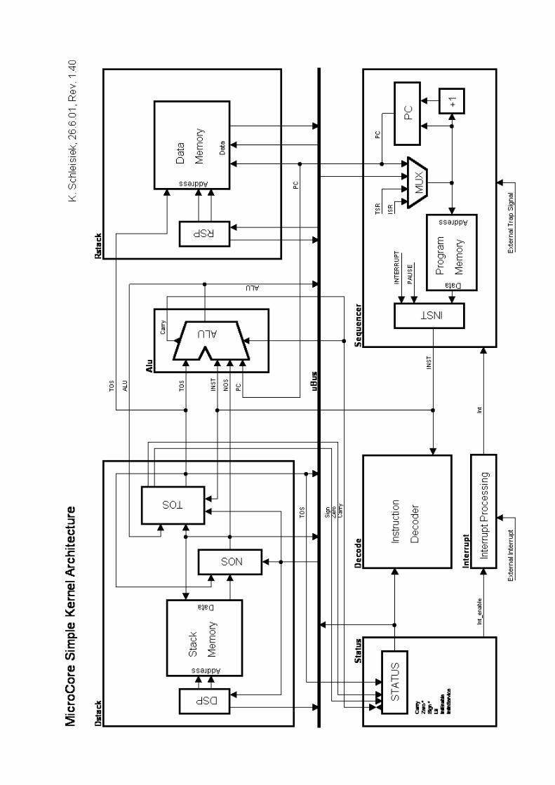
1 Hardware Architecture
MicroCore is a dual-stack, Harvard architecture with three memory areas which can be accessed inparallel: Data-stack (RAM), Data-memory and return-stack (RAM), and Program-memory (ROM).
The architecture diagrams depict all busses which are needed, not showing the control signals whichare generated in the Instruction Decoder from instruction register INST and status register STATUSas inputs.
All instructions without exception are 8-bits wide, and they are stored in the program-memoryROM. Due to the way literal values of any magnitude can be composed from sequences of literalinstructions, all data-paths and memories are scaleable to any word width without any change in theinstruction set.
The data-paths are made up of the data-stack Dstack, the ALU, and of the data-memory and return-stack Rstack, as well as of uBus, and of the registers NOS (Next-Of-Stack), and TOS (Top-Of-Stack), which are in between the data-stack and the ALU.
The data-stack is realised by the Stack Memory RAM under control of the Data-Stack-Pointer DSP,and the topmost stack items are held in registers NOS and TOS. Very often, the size of the StackMemory needed will be small enough to fit inside the FPGA implementing MicroCore.
The ALU's inputs come from TOS on one side and from NOS, INST or PC on the other side.Therefore, TOS+PC will be available for relative branching, and TOS+INST for post-incrementingmemory addresses.
The upper end of the Data Memory is utilised as the return-stack under control of the Return-Stack-Pointer RSP. The address range which is physically used by the return-stack doubles as memorymapped I/O (not shown in the diagrams).
The Sequencer generates the Program Memory address for the next instruction which can have anumber of sources:
• The Program Counter PC for a sequential instruction,
• the ALU for a relative branch or call,
• the TOS register for an absolute branch or call,
• the return-stack inside the Data Memory for a return instruction,
• the fixed Interrupt Service Routine address ISR as part of an interrupt acknowledge cycle, or
• the fixed Trap Service Routine address TSR for an external trap signal or the PAUSEinstruction.
The STATUS register has been singled out as a separate entity because it is composed of status bitsgenerated from several sources.
The Interrupt Processing unit takes care of synchronising and masking an application specificnumber of external interrupt sources.
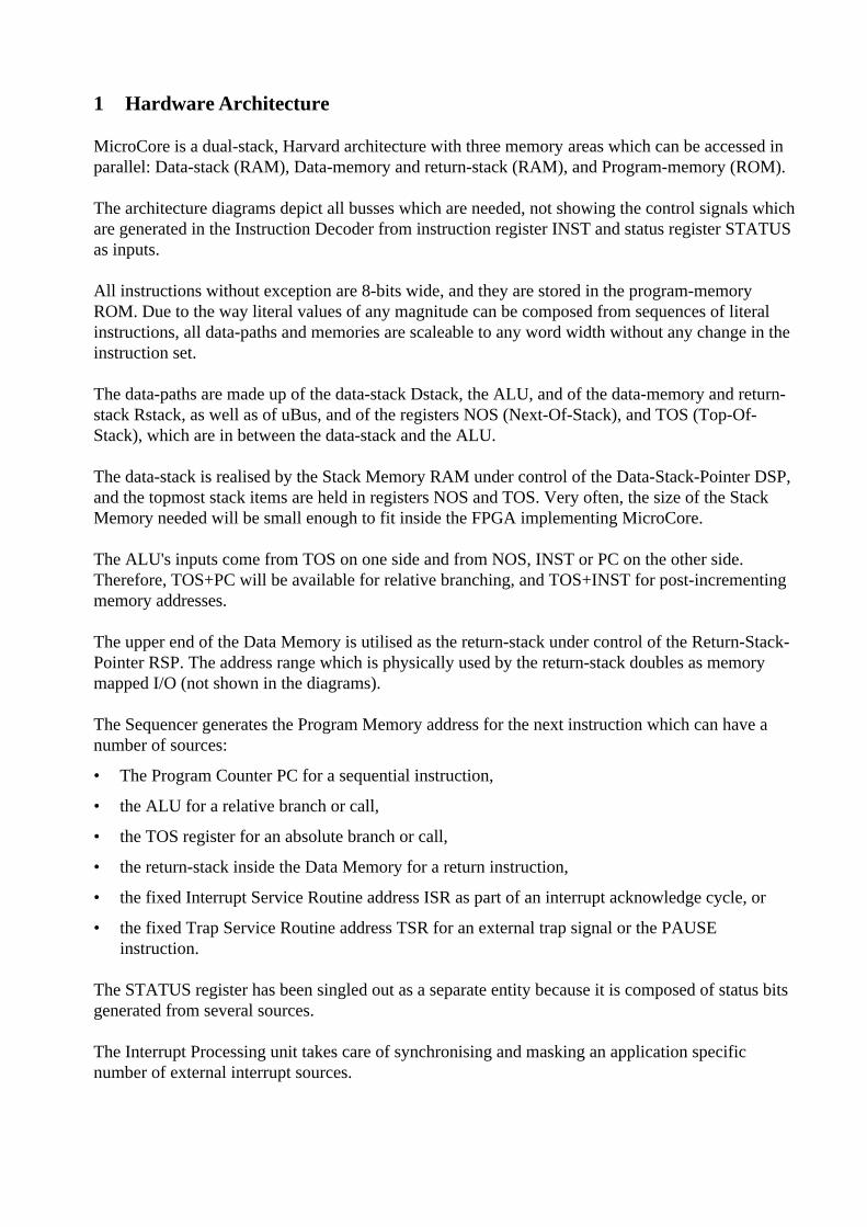
The extended architecture adds "nice to have" capabilities:
1. Feeding the return-stack address from RSP into the ALU allows to compute TOS+RSP forreturn-stack relative indexed addressing. This is all that is needed to support local variables in C.
2. Adding a TASK register that also feeds into the ALU allows to compute TOS+TASK for base-indexed addressing of e.g. the task-descriptor-block of the active task in a multitaskingenvironment.
3. Adding a Top-Of-Return-stack (TOR) register and a decrementer allows to realise very fast FOR... NEXT loops.
All these extension add capabilities to the simple architecture and they may be selectivelyimplemented according to the needs of the application. Please note that all capabilities of theextended architecture are supported in the standard instruction set.
2 Instruction Architecture
Each instruction is always 8 bits wide. Scalability is achieved on the source-code level becauseliteral values may be compiled into different object code depending on the data-word width. Referto [3 instruction structures] for a discussion of the literal representation used, which is characterisedby its "prefix" nature dubbed "Vertical instruction set with literal prefixes" in the paper. To myknowledge, this type of code has been invented by Michael D. May and used in the Transputer forthe first time.
It has two advantages and one drawback compared to other instruction set structures:
Every instruction is "self contained" and therefore, this type of code can be interrupted between anytwo instructions, simplifying interrupt hardware and minimising interrupt latency to the max.
Long literals can be composed of a sequence of literal instructions which are concatenated in theTOS register. Therefore, this type of code is independent of the data-word width.
Prefix code has the highest instruction fetch rate compared to the two other instruction typesdiscussed in the paper. Therefore, it is not really the technology of choice for demanding real-time applications. A way out would be to fetch several instructions per memory access but thatintroduces unpleasant complexity for branch destinations.
Keeping in mind that MicroCore is about putting a very simple and small processor core intoFPGAs for simple, embedded control, the latter drawback is tolerable because the instruction fetchdelay even when using an external ROM will hardly dominate total processor delay because allFPGA based processor logic will be substantially slower than an ASIC implementation anyway.
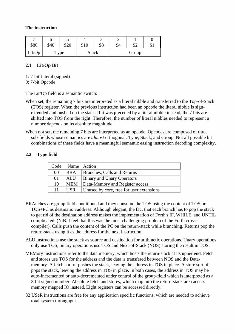
The instruction
7$80
6$40
5$20
4$10
3$8
2$4
1$2
0$1
Lit/Op Type Stack Group
2.1 Lit/Op Bit
1: 7-bit Literal (signed)0: 7-bit Opcode
The Lit/Op field is a semantic switch:
When set, the remaining 7 bits are interpreted as a literal nibble and transferred to the Top-of-Stack(TOS) register. When the previous instruction had been an opcode the literal nibble is sign-extended and pushed on the stack. If it was preceded by a literal nibble instead, the 7 bits areshifted into TOS from the right. Therefore, the number of literal nibbles needed to represent anumber depends on its absolute magnitude.
When not set, the remaining 7 bits are interpreted as an opcode. Opcodes are composed of threesub-fields whose semantics are almost orthogonal: Type, Stack, and Group. Not all possible bitcombinations of these fields have a meaningful semantic easing instruction decoding complexity.
2.2 Type field
Code Name Action00 BRA Branches, Calls and Returns01 ALU Binary and Unary Operators10 MEM Data-Memory and Register access11 USR Unused by core, free for user extensions
BRAnches are group field conditioned and they consume the TOS using the content of TOS orTOS+PC as destination address. Although elegant, the fact that each branch has to pop the stackto get rid of the destination address makes the implementation of Forth's IF, WHILE, and UNTILcomplicated. (N.B. I feel that this was the most challenging problem of the Forth cross-compiler). Calls push the content of the PC on the return-stack while branching. Returns pop thereturn-stack using it as the address for the next instruction.
ALU instructions use the stack as source and destination for arithmetic operations. Unary operationsonly use TOS, binary operations use TOS and Next-of-Stack (NOS) storing the result in TOS.
MEMory instructions refer to the data memory, which hosts the return-stack at its upper end. Fetchand stores use TOS for the address and the data is transfered between NOS and the Data-memory. A fetch sort of pushes the stack, leaving the address in TOS in place. A store sort ofpops the stack, leaving the address in TOS in place. In both cases, the address in TOS may beauto-incremented or auto-decremented under control of the group-field which is interpreted as a3-bit signed number. Absolute fetch and stores, which map into the return-stack area accessmemory mapped IO instead. Eight registers can be accessed directly.
32 USeR instructions are free for any application specific functions, which are needed to achievetotal system throughput.

2.3 Stack field
Code Name Action00 NONE Type dependent01 POP Stack->NOS->TOS10 PUSH TOS->NOS->Stack11 BOTH Type dependent
POP pops and PUSH pushes the data stack. The stack semantics of the remaining states NONE andBOTH depend on type and on external signals interrupt and pause. This is where the opcode fieldsare non-orthogonal creating instruction decoding complexity, which is gracefully hidden by theVHDL synthesiser.
2.4 Group field
The semantics of the group field depend on the type field and in the case of ALU also on the stackfield.
Of the binary operators NOS is used to realise SWAP and OVER.
Unary operations are detailed below.
Of the conditions, NEVER is used to realise NOP, DUP and DROP. DBR (Decrement-and-BRanch) supports the use of the Top-Of-Return-stack as a loop index. PAUSE and INT areconditions to aid in processing external events interrupt and pause.
Of the registers, TOR is used to implement R@ and RSTACK implements >R and R>.
3 Instruction Semantics
In the following tables the LIT-field is marked with - and +.
This indicates the following two cases:‘-’: The previous instruction has also been an opcode; TOS holds the top-of-stack value.‘+’: The previous instruction(s) have been literal nibbles; TOS holds a "fresh" literal value.
Code Binary-OpsALU
Unary-OpsALU
ConditionsBRA
RegistersMEM
000 ADD NOT NEVER STATUS001 SUB SL ZERO TOR010 ADC ASR SIGN RSTACK011 SBC LSR CARRY LOCAL100 AND ROR PAUSE RSP101 OR ROL INT DSP110 XOR ZEQU DBR TASK111 NOS CC ALWAYS FLAGS / IE
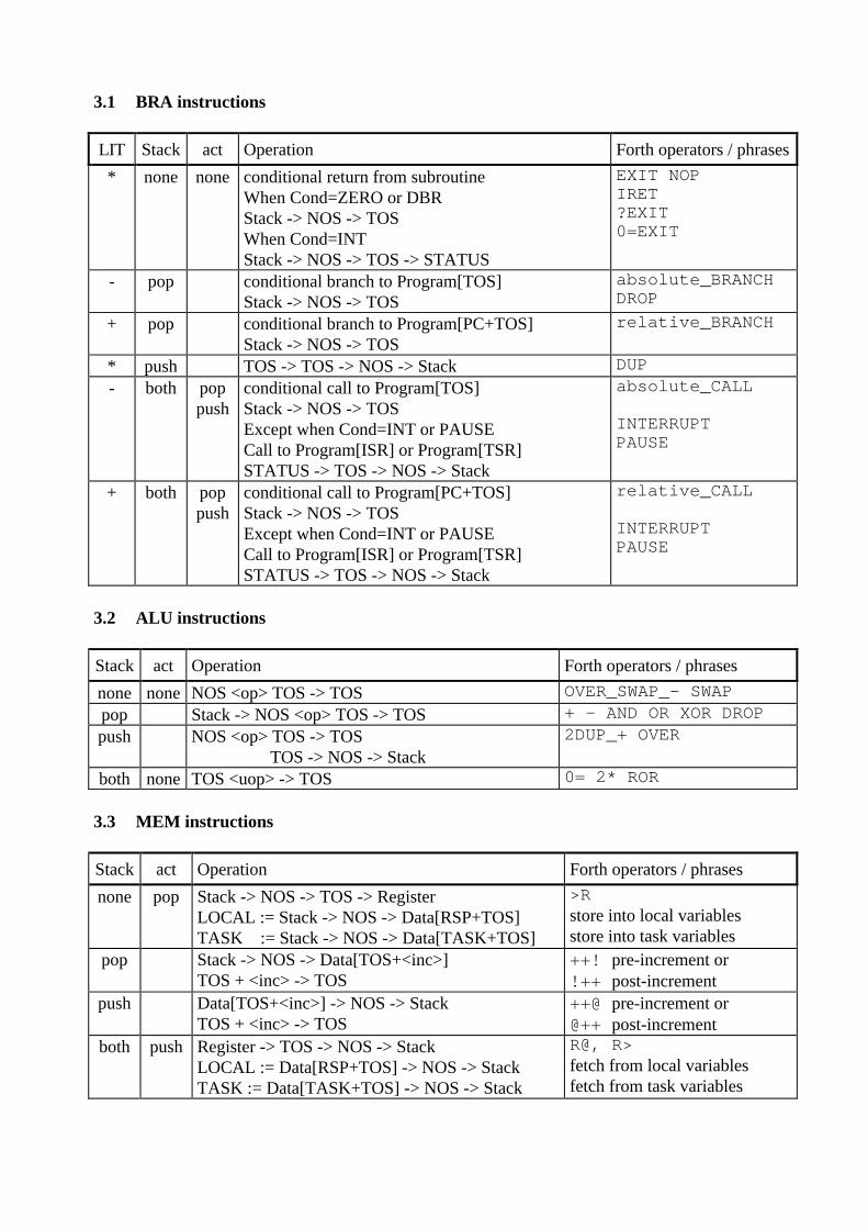
3.1 BRA instructions
LIT Stack act Operation Forth operators / phrases
* none none conditional return from subroutineWhen Cond=ZERO or DBRStack -> NOS -> TOSWhen Cond=INTStack -> NOS -> TOS -> STATUS
EXIT NOPIRET?EXIT0=EXIT
- pop conditional branch to Program[TOS]Stack -> NOS -> TOS
absolute_BRANCHDROP
+ pop conditional branch to Program[PC+TOS]Stack -> NOS -> TOS
relative_BRANCH
* push TOS -> TOS -> NOS -> Stack DUP- both pop
pushconditional call to Program[TOS]Stack -> NOS -> TOSExcept when Cond=INT or PAUSECall to Program[ISR] or Program[TSR]STATUS -> TOS -> NOS -> Stack
absolute_CALL
INTERRUPTPAUSE
+ both poppush
conditional call to Program[PC+TOS]Stack -> NOS -> TOSExcept when Cond=INT or PAUSECall to Program[ISR] or Program[TSR]STATUS -> TOS -> NOS -> Stack
relative_CALL
INTERRUPTPAUSE
3.2 ALU instructions
Stack act Operation Forth operators / phrases
none none NOS <op> TOS -> TOS OVER_SWAP_- SWAPpop Stack -> NOS <op> TOS -> TOS + - AND OR XOR DROPpush NOS <op> TOS -> TOS
TOS -> NOS -> Stack2DUP_+ OVER
both none TOS <uop> -> TOS 0= 2* ROR
3.3 MEM instructions
Stack act Operation Forth operators / phrases
none pop Stack -> NOS -> TOS -> RegisterLOCAL := Stack -> NOS -> Data[RSP+TOS]TASK := Stack -> NOS -> Data[TASK+TOS]
>Rstore into local variablesstore into task variables
pop Stack -> NOS -> Data[TOS+<inc>]TOS + <inc> -> TOS
++! pre-increment or!++ post-increment
push Data[TOS+<inc>] -> NOS -> StackTOS + <inc> -> TOS
++@ pre-increment or@++ post-increment
both push Register -> TOS -> NOS -> StackLOCAL := Data[RSP+TOS] -> NOS -> StackTASK := Data[TASK+TOS] -> NOS -> Stack
R@, R>fetch from local variablesfetch from task variables
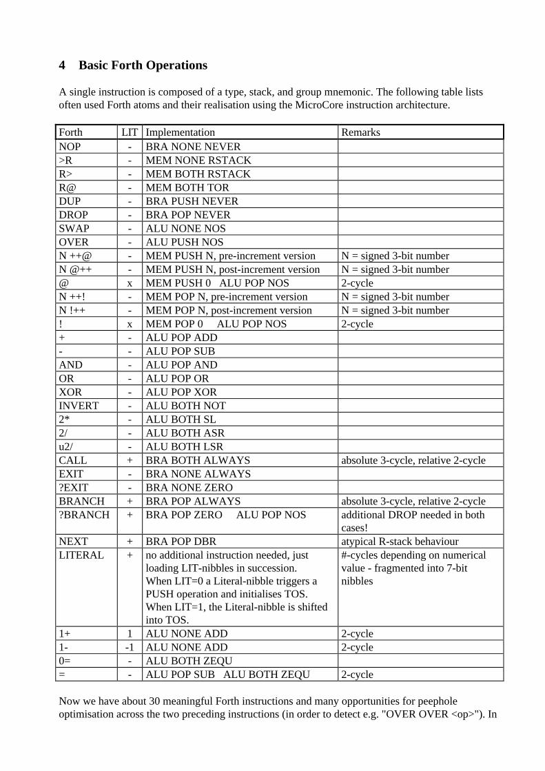
4 Basic Forth Operations
A single instruction is composed of a type, stack, and group mnemonic. The following table listsoften used Forth atoms and their realisation using the MicroCore instruction architecture.
Forth LIT Implementation RemarksNOP - BRA NONE NEVER>R - MEM NONE RSTACKR> - MEM BOTH RSTACKR@ - MEM BOTH TORDUP - BRA PUSH NEVERDROP - BRA POP NEVERSWAP - ALU NONE NOSOVER - ALU PUSH NOSN ++@ - MEM PUSH N, pre-increment version N = signed 3-bit numberN @++ - MEM PUSH N, post-increment version N = signed 3-bit number@ x MEM PUSH 0 ALU POP NOS 2-cycleN ++! - MEM POP N, pre-increment version N = signed 3-bit numberN !++ - MEM POP N, post-increment version N = signed 3-bit number! x MEM POP 0 ALU POP NOS 2-cycle+ - ALU POP ADD- - ALU POP SUBAND - ALU POP ANDOR - ALU POP ORXOR - ALU POP XORINVERT - ALU BOTH NOT2* - ALU BOTH SL2/ - ALU BOTH ASRu2/ - ALU BOTH LSRCALL + BRA BOTH ALWAYS absolute 3-cycle, relative 2-cycleEXIT - BRA NONE ALWAYS?EXIT - BRA NONE ZEROBRANCH + BRA POP ALWAYS absolute 3-cycle, relative 2-cycle?BRANCH + BRA POP ZERO ALU POP NOS additional DROP needed in both
cases!NEXT + BRA POP DBR atypical R-stack behaviourLITERAL + no additional instruction needed, just
loading LIT-nibbles in succession.When LIT=0 a Literal-nibble triggers aPUSH operation and initialises TOS.When LIT=1, the Literal-nibble is shiftedinto TOS.
#-cycles depending on numericalvalue - fragmented into 7-bitnibbles
1+ 1 ALU NONE ADD 2-cycle1- -1 ALU NONE ADD 2-cycle0= - ALU BOTH ZEQU= - ALU POP SUB ALU BOTH ZEQU 2-cycle
Now we have about 30 meaningful Forth instructions and many opportunities for peepholeoptimisation across the two preceding instructions (in order to detect e.g. "OVER OVER <op>"). In
addition, there are additional useful opcodes like CARRY-BRANCH and NEGATIVE-BRANCH,which are usually not present in Forth.
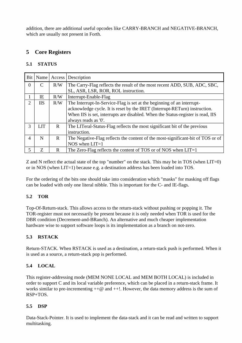
5 Core Registers
5.1 STATUS
Bit Name Access Description
0 C R/W The Carry-Flag reflects the result of the most recent ADD, SUB, ADC, SBC,SL, ASR, LSR, ROR, ROL instruction.
1 IE R/W Interrupt-Enable-Flag2 IIS R/W The Interrupt-In-Service-Flag is set at the beginning of an interrupt-
acknowledge cycle. It is reset by the IRET (Interrupt-RETurn) instruction.When IIS is set, interrupts are disabled. When the Status-register is read, IISalways reads as '0'.
3 LIT R The LITeral-Status-Flag reflects the most significant bit of the previousinstruction.
4 N R The Negative-Flag reflects the content of the most-significant-bit of TOS or ofNOS when LIT=1
5 Z R The Zero-Flag reflects the content of TOS or of NOS when LIT=1
Z and N reflect the actual state of the top "number" on the stack. This may be in TOS (when LIT=0)or in NOS (when LIT=1) because e.g. a destination address has been loaded into TOS.
For the ordering of the bits one should take into consideration which "masks" for masking off flagscan be loaded with only one literal nibble. This is important for the C- and IE-flags.
5.2 TOR
Top-Of-Return-stack. This allows access to the return-stack without pushing or popping it. TheTOR-register must not necessarily be present because it is only needed when TOR is used for theDBR condition (Decrement-and-BRanch). An alternative and much cheaper implementationhardware wise to support software loops is its implementation as a branch on not-zero.
5.3 RSTACK
Return-STACK. When RSTACK is used as a destination, a return-stack push is performed. When itis used as a source, a return-stack pop is performed.
5.4 LOCAL
This register-addressing mode (MEM NONE LOCAL and MEM BOTH LOCAL) is included inorder to support C and its local variable preference, which can be placed in a return-stack frame. Itworks similar to pre-incrementing ++@ and ++!. However, the data memory address is the sum ofRSP+TOS.
5.5 DSP
Data-Stack-Pointer. It is used to implement the data-stack and it can be read and written to supportmultitasking.
5.6 RSP
Return-Stack-Pointer. It is used to implement the return-stack which is located at the upper end ofthe data memory and it can be read and written to support multitasking and stack-frames for C-support.
5.7 FLAGS (read) / IE (write)
This is a pair of registers – FLAGS for reading, IE (Interrupt Enable) for writing.
An interrupt condition exists as long as any bit in FLAGS is set whose corresponding bit in IE hasalso been set. Interrupt processing will be performed when the processor is not already executing aninterrupt (IIS-status-bit not set) and interrupts are enabled (IE-status-bit set).
Typically, at the beginning of interrupt processing (after calling the hard-wired interrupt handleraddress ISR), the FLAGS-register will be read. One specific bit is associated with each potentialinterrupt source. When a certain interrupt has been asserted, its associated bit will be set. It is theresponsibility of the interrupt service routine (ISR) of a specific interrupt to reset its interrupt signalbefore the end of the ISR.
IE (Interrupt Enable) is a register, which can only be written, and it holds one enable bit for eachinterrupt source. Setting or resetting interrupt enable bits is done in a peculiar way, which could becalled "bit-wise writing":
When IE is written, the least significant bit determines whether individual IE-bits will be set ('1') orreset ('0'). All other bits written to IE select those enable bits, which will be affected by the writeoperation. Those bits which are set ('1') will be written to, those bits which are not set ('0') will notbe changed at all. This way individual interrupt enable bits may be changed in a single cycle withoutaffecting other IE-bits.
5.8 TASK
The TASK register can be read and written via memory mapped I/O (address = -1). It holds anaddress which points at the Task Description Block (TDB) of the active task. The implementationof the multitasking mechanism is operating system dependent. Variables that are local to a task canbe accessed via the MEM NONE TASK (store) and MEM BOTH TASK (fetch) instructions. Itworks similar to pre-incrementing ++@ and ++!. However, the data memory address is the sum ofTASK+TOS.
If the TASK register is not used for multitasking support, it constitutes a general base register for apre-incrementing base-offset addressing mode.
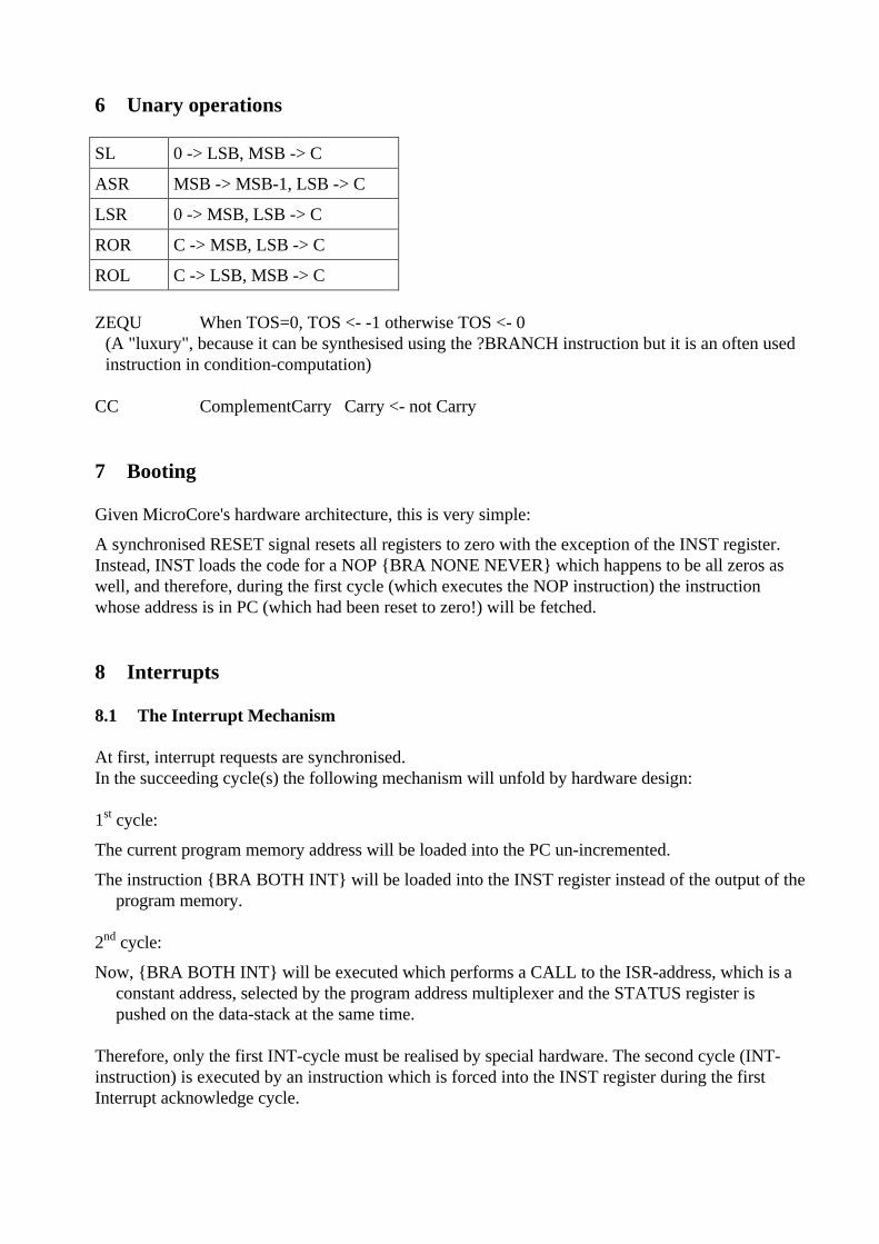
6 Unary operations
SL 0 -> LSB, MSB -> C
ASR MSB -> MSB-1, LSB -> C
LSR 0 -> MSB, LSB -> C
ROR C -> MSB, LSB -> C
ROL C -> LSB, MSB -> C
ZEQU When TOS=0, TOS <- -1 otherwise TOS <- 0(A "luxury", because it can be synthesised using the ?BRANCH instruction but it is an often usedinstruction in condition-computation)
CC ComplementCarry Carry <- not Carry
7 Booting
Given MicroCore's hardware architecture, this is very simple:
A synchronised RESET signal resets all registers to zero with the exception of the INST register.Instead, INST loads the code for a NOP {BRA NONE NEVER} which happens to be all zeros aswell, and therefore, during the first cycle (which executes the NOP instruction) the instructionwhose address is in PC (which had been reset to zero!) will be fetched.
8 Interrupts
8.1 The Interrupt Mechanism
At first, interrupt requests are synchronised.In the succeeding cycle(s) the following mechanism will unfold by hardware design:
1st cycle:
The current program memory address will be loaded into the PC un-incremented.
The instruction {BRA BOTH INT} will be loaded into the INST register instead of the output of theprogram memory.
2nd cycle:
Now, {BRA BOTH INT} will be executed which performs a CALL to the ISR-address, which is aconstant address, selected by the program address multiplexer and the STATUS register ispushed on the data-stack at the same time.
Therefore, only the first INT-cycle must be realised by special hardware. The second cycle (INT-instruction) is executed by an instruction which is forced into the INST register during the firstInterrupt acknowledge cycle.
8.2 Handling Multiple Interrupt Sources
Whenever an interrupt source whose corresponding interrupt enable bit is set in the IE-register isasserted its associated bit in the FLAGS-register will be set and an interrupt condition exists. Aninterrupt acknowledge cycle will be executed when the processor is not currently executing aninterrupt (IIS-bit not set) and interrupts are globally enabled (IE-bit of the STATUS-register set).
Please note that neither the call to the ISR-address nor reading the FLAGS-register will clear theFLAGS register. It is the responsibility of each single interrupt server to reset its interrupt signal inits interrupt service routine.
9 Multitasking
The transputer has been a very innovative processor indeed, which was focused on multitasking,which is completely realised in hardware. Nice as this feature and its underlying philosophy may be,this lead to ramifications in order to simplify the necessary hardware support which did make thetransputer difficult to market and eventually, despite a lot of money from British and Europeantaxpayers, it was a commercial failure.
Nevertheless, hardware support for multitasking seems to be an attractive feature greatlysimplifying software engineering for complex systems. Analysing the real needs w.r.t. multitaskingsupport it occurred to me that a full-blown task switch mechanism in hardware is not really needed.Instead, a mechanism which would allow to access resources which may not be ready yet usingfetch and store without the need to explicitly query associated status flags beforehand is all that isneeded to hide multitasking pains from the application programmer.
Therefore, MicroCore has a PAUSE instruction and a TRAP mechanism to support multitasking or,to be less ambitious, to deal with busy resources. Fortunately, it turned out that the implementationof this mechanism in MicroCore is very cheap and therefore, it is build into the core from the verybeginning. If not used for multitasking, it is a nice basis for a breakpoint debugger.
9.1 TRAP signal
An additional external control signal has been added: TRAP. When the processor intends to accessa resource, the resource may not be ready yet. In such an event, it can assert the TRAP signal beforethe end of the current execution cycle (before the rising CLK edge). This disables latching of thenext processor state in all registers but the INST register loading the PAUSE instruction {BRABOTH PAUSE} instead of the next instruction from program memory.
In the next processor cycle, {BRA BOTH PAUSE} will be executed calling the TSR-address (TaskService Routine). Similar to an interrupt, the STATUS register is pushed on the data stack at thesame time.
The TSR-address will typically hold a branch to code, which will perform a task switch dependingon the operating system. Please note that the return address pushed on the return-stack is the addressof the instruction following the one that caused the TRAP. Therefore, before re-activating thetrapped task again, the return address on the return-stack has to be decremented by one prior toexecuting the IRET instruction {BRA NONE INT} in order to re-execute the instruction, whichcaused the trap previously. Please note that no other parameter reconstruction operation prior to re-execution has to be made because the TRAP cycle fully preserves all registers but the INST register.
The TRAP mechanism is fully independent of the interrupt mechanism. It only adds one cycle ofdelay to an interrupt acknowledge when both an interrupt request and a TRAP signal coincide.
In essence, the TRAP mechanism allows to access external resources without having to query statusbits to ascertain the availability/readiness of a resource. This greatly simplifies the software neededfor e.g. serial channels for communicating with external devices or processes.
10 Data Memory Access
Data memory access operators ++@ and ++! have been defined for a pre-incrementingimplementation, access operators @++ and !++ have been defined for a post-incrementingimplementation and this has been carried through to the cross-compiler.
From a programmers point of view, the pre-incrementing implementation is easier to handlebecause you only have to worry about a potential address offset when you need it, whereas in thepost-incrementing implementation you have to worry about an offset in the preceding memoryaccess.
From a hardware point of view, the post-incrementing implementation is more efficient because ittakes the memory address directly from TOS. In the pre-incrementing implementation, the addressis the output of the ALU-adder and therefore, it will arrive at the data memory later. If this memoryis fast compared to one processor cycle this may not result in an overall performance degradationnevertheless. Alternatively, an additional processor cycle may be added to the memory accessoperators using the CLK_EN signal of the core.
When LOCAL data access is realised, the same problem exists. The memory address is the outputof the ALU-adder, adding the offset in TOS and the RSP. In this case, the pre-incrementingimplementation may be chosen because the timing problem does exist anyway.
In addition, most branch and call instructions will be relative, using the adder in order to computethe destination address. Because the offset is build up in TOS prior to the branch/call instruction theaddress computation can already be started in the previous cycle. This has been realised in the post-incrementing MicroCore model.
I believe that pre-/post-increment timing constraints will only be an issue when MicroCore isrealised as an ASIC anyway. In FPGA implementations the (external) RAM can be expected to befast enough.
Ideally, the cross-compiler would be made smart enough to compile the proper code based on a pre-incrementing syntax even if the implementation is post-incrementing. Otherwise, a change ofimplementation would break the code.

11 Software Development
An interactive software development environment for MicroCore is rather straightforward and inessence, it has been realised before when I worked on the IX1 field bus processor.
A "debugable MicroCore" has an additional Centronics interface, which connects to a PC serving asthe host. The program memory, which must be realised as a RAM, can be loaded across thisinterface. After loading the application, a very simple debug kernel takes control exchangingmessages with the host, using the Centronics interface as umbilical.
11.1 Forth Cross-Compiler
It exists and it loads on top of Win32Forth because it’s a free 32-bit system. It produces a binaryimage for the program memory as well as a VHDL file, which behaves as the program memory in aVHDL simulation. (Unfortunately, the cross-compiler is written in such a way that the currentimplementation only supports a maximum data-word width of 31 instead of 32 bits.)
It is a short but rather complex piece of code and my 4th or so iteration on implementing a Forthcross-compiler in Forth.
The most challenging aspect was compiling MicroCore's branches, which, as relative branches, arepreceded by a variable number of literal nibbles. It took several attempts and months to solve theproblem. Now, the cross-compiler at first tries to get away with one literal nibble for the branchoffset. If it turns out that this is not sufficient space for the branch offset at the closing ELSE,THEN, UNTIL, or REPEAT, the source code is re-interpreted again, leaving space for the requirednumber of literal nibbles in front of the branch opcode.
Another challenge is compiling Forth's IF, WHILE, and UNTIL because, after the branch, you stillhave the flag remaining on the stack. Therefore, a DROP has to be inserted after the IF and theTHEN in an IF ... THEN phrase. There's still a lot of room for optimisations and the compiled codesometimes looks sub-optimal with sequences of DUP DROP sprinkled across the code as remainsof backward branching loops.
11.2 C Cross-Compiler
A first implementation has been realised for an earlier version of MicroCore at the technicaluniversity of Brugg/Windisch, Switzerland. The compiler is based on the LCC compiler, and aMicroCore back-end has been implemented.
It turned out that the LOCAL addressing mode is all that is needed to come to grips with C's localvariable preference. Actually, the LOCAL addressing mode does not really add any additionalfunctionality to the core but it is a mechanism to come to grips with state-of-the-art C-compilertechnology. The LOCAL addressing mode with its additional hardware consumption could go awayas soon as an optimiser has been realised which is capable of transforming local variable accessesinto appropriate data-stack manipulations.
Once MicroCore actually exists, running on a prototype board, another iteration will be made.
12 Project Status
The VHDL code exists and can be released. The identical code could be synthesised using theSynplify and the Leonardo synthesisers targeting Xilinx and Altera FPGAs.
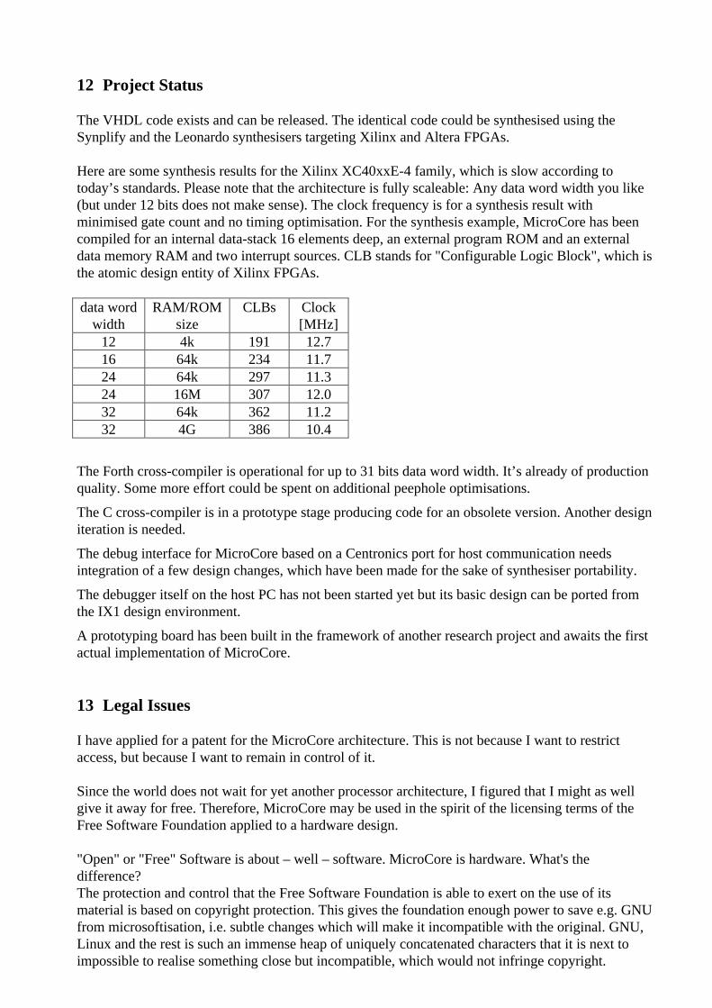
Here are some synthesis results for the Xilinx XC40xxE-4 family, which is slow according totoday’s standards. Please note that the architecture is fully scaleable: Any data word width you like(but under 12 bits does not make sense). The clock frequency is for a synthesis result withminimised gate count and no timing optimisation. For the synthesis example, MicroCore has beencompiled for an internal data-stack 16 elements deep, an external program ROM and an externaldata memory RAM and two interrupt sources. CLB stands for "Configurable Logic Block", which isthe atomic design entity of Xilinx FPGAs.
data wordwidth
RAM/ROMsize
CLBs Clock[MHz]
12 4k 191 12.716 64k 234 11.724 64k 297 11.324 16M 307 12.032 64k 362 11.232 4G 386 10.4
The Forth cross-compiler is operational for up to 31 bits data word width. It’s already of productionquality. Some more effort could be spent on additional peephole optimisations.
The C cross-compiler is in a prototype stage producing code for an obsolete version. Another designiteration is needed.
The debug interface for MicroCore based on a Centronics port for host communication needsintegration of a few design changes, which have been made for the sake of synthesiser portability.
The debugger itself on the host PC has not been started yet but its basic design can be ported fromthe IX1 design environment.
A prototyping board has been built in the framework of another research project and awaits the firstactual implementation of MicroCore.
13 Legal Issues
I have applied for a patent for the MicroCore architecture. This is not because I want to restrictaccess, but because I want to remain in control of it.
Since the world does not wait for yet another processor architecture, I figured that I might as wellgive it away for free. Therefore, MicroCore may be used in the spirit of the licensing terms of theFree Software Foundation applied to a hardware design.
"Open" or "Free" Software is about – well – software. MicroCore is hardware. What's thedifference?The protection and control that the Free Software Foundation is able to exert on the use of itsmaterial is based on copyright protection. This gives the foundation enough power to save e.g. GNUfrom microsoftisation, i.e. subtle changes which will make it incompatible with the original. GNU,Linux and the rest is such an immense heap of uniquely concatenated characters that it is next toimpossible to realise something close but incompatible, which would not infringe copyright.
The situation for MicroCore is radically different: As the name implies, it is simple. Once you haveexplained the architecture and instruction set to an experienced VHDL programmer, he will comeup with an original implementation in three months or less without infringing on the copyright ofthe original VHDL model. This is why I have applied for patent protection.
When MicroCore catches on, I am prepared to transfer the patent rights to a public, non-profitorganisation. At present, you can use it in the spirit of the Free Software Foundation's licensingterms. I will work on specific licensing terms adapted to MicroCore, but that is not a top priority,it’s rather a boring necessity.
14 Acknowledgements
I would like to thank a number of people without which MicroCore would be different or not existat all, namely:Chuck Moore, who started it all with the design of the NC4000. Norbert Ellenberger, who backedthe design of the FRP1600 which paved the way for the IX1. Christophe Lavarenne who introducedthe Transputer innovations to me. Adolf Krüger, without whom the literal accumulator wouldprobably still be in a separate register instead of on the stack.
15 MicroCore Basics in VHDL
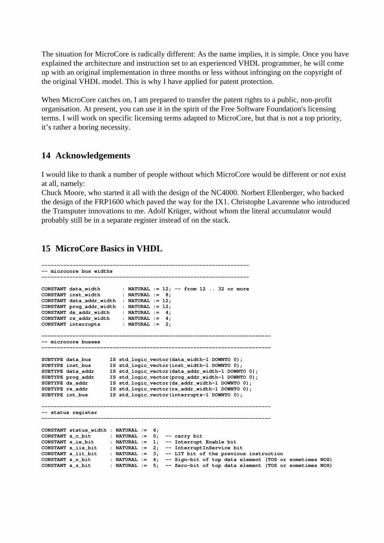
--------------------------------------------------------------------- microcore bus widths-------------------------------------------------------------------
CONSTANT data_width : NATURAL := 12; -- from 12 .. 32 or moreCONSTANT inst_width : NATURAL := 8;CONSTANT data_addr_width : NATURAL := 12;CONSTANT prog_addr_width : NATURAL := 12;CONSTANT ds_addr_width : NATURAL := 4;CONSTANT rs_addr_width : NATURAL := 4;CONSTANT interrupts : NATURAL := 2;
---------------------------------------------------------------------------- microcore busses--------------------------------------------------------------------------
SUBTYPE data_bus IS std_logic_vector(data_width-1 DOWNTO 0);SUBTYPE inst_bus IS std_logic_vector(inst_width-1 DOWNTO 0);SUBTYPE data_addr IS std_logic_vector(data_addr_width-1 DOWNTO 0);SUBTYPE prog_addr IS std_logic_vector(prog_addr_width-1 DOWNTO 0);SUBTYPE ds_addr IS std_logic_vector(ds_addr_width-1 DOWNTO 0);SUBTYPE rs_addr IS std_logic_vector(rs_addr_width-1 DOWNTO 0);SUBTYPE int_bus IS std_logic_vector(interrupts-1 DOWNTO 0);
---------------------------------------------------------------------------- status register--------------------------------------------------------------------------
CONSTANT status_width : NATURAL := 6;CONSTANT s_c_bit : NATURAL := 0; -- carry bitCONSTANT s_ie_bit : NATURAL := 1; -- Interrupt Enable bitCONSTANT s_iis_bit : NATURAL := 2; -- InterruptInService bitCONSTANT s_lit_bit : NATURAL := 3; -- LIT bit of the previous instructionCONSTANT s_n_bit : NATURAL := 4; -- Sign-bit of top data element (TOS or sometimes NOS)CONSTANT s_z_bit : NATURAL := 5; -- Zero-bit of top data element (TOS or sometimes NOS)
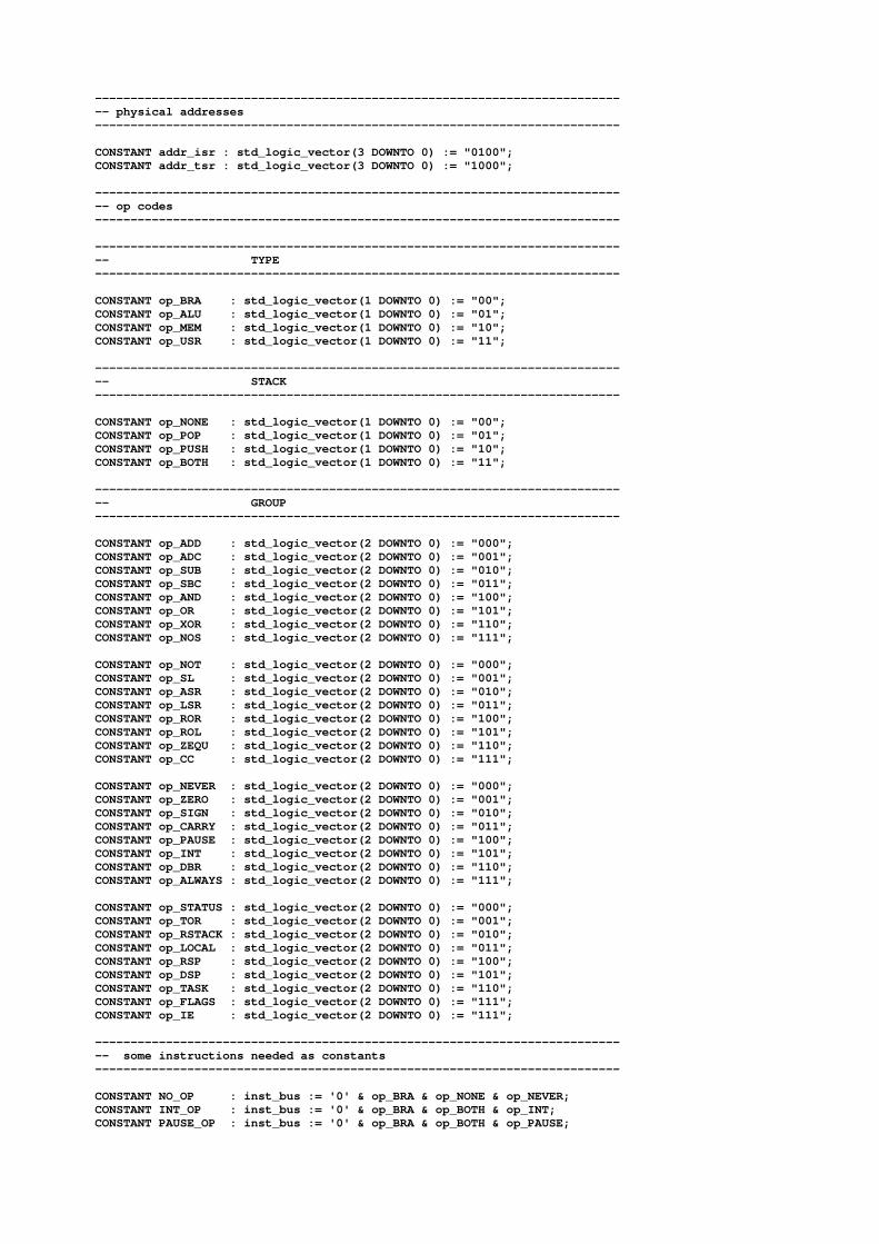
---------------------------------------------------------------------------- physical addresses--------------------------------------------------------------------------
CONSTANT addr_isr : std_logic_vector(3 DOWNTO 0) := "0100";CONSTANT addr_tsr : std_logic_vector(3 DOWNTO 0) := "1000";
---------------------------------------------------------------------------- op codes--------------------------------------------------------------------------
---------------------------------------------------------------------------- TYPE--------------------------------------------------------------------------
CONSTANT op_BRA : std_logic_vector(1 DOWNTO 0) := "00";CONSTANT op_ALU : std_logic_vector(1 DOWNTO 0) := "01";CONSTANT op_MEM : std_logic_vector(1 DOWNTO 0) := "10";CONSTANT op_USR : std_logic_vector(1 DOWNTO 0) := "11";
---------------------------------------------------------------------------- STACK--------------------------------------------------------------------------
CONSTANT op_NONE : std_logic_vector(1 DOWNTO 0) := "00";CONSTANT op_POP : std_logic_vector(1 DOWNTO 0) := "01";CONSTANT op_PUSH : std_logic_vector(1 DOWNTO 0) := "10";CONSTANT op_BOTH : std_logic_vector(1 DOWNTO 0) := "11";
---------------------------------------------------------------------------- GROUP--------------------------------------------------------------------------
CONSTANT op_ADD : std_logic_vector(2 DOWNTO 0) := "000";CONSTANT op_ADC : std_logic_vector(2 DOWNTO 0) := "001";CONSTANT op_SUB : std_logic_vector(2 DOWNTO 0) := "010";CONSTANT op_SBC : std_logic_vector(2 DOWNTO 0) := "011";CONSTANT op_AND : std_logic_vector(2 DOWNTO 0) := "100";CONSTANT op_OR : std_logic_vector(2 DOWNTO 0) := "101";CONSTANT op_XOR : std_logic_vector(2 DOWNTO 0) := "110";CONSTANT op_NOS : std_logic_vector(2 DOWNTO 0) := "111";
CONSTANT op_NOT : std_logic_vector(2 DOWNTO 0) := "000";CONSTANT op_SL : std_logic_vector(2 DOWNTO 0) := "001";CONSTANT op_ASR : std_logic_vector(2 DOWNTO 0) := "010";CONSTANT op_LSR : std_logic_vector(2 DOWNTO 0) := "011";CONSTANT op_ROR : std_logic_vector(2 DOWNTO 0) := "100";CONSTANT op_ROL : std_logic_vector(2 DOWNTO 0) := "101";CONSTANT op_ZEQU : std_logic_vector(2 DOWNTO 0) := "110";CONSTANT op_CC : std_logic_vector(2 DOWNTO 0) := "111";
CONSTANT op_NEVER : std_logic_vector(2 DOWNTO 0) := "000";CONSTANT op_ZERO : std_logic_vector(2 DOWNTO 0) := "001";CONSTANT op_SIGN : std_logic_vector(2 DOWNTO 0) := "010";CONSTANT op_CARRY : std_logic_vector(2 DOWNTO 0) := "011";CONSTANT op_PAUSE : std_logic_vector(2 DOWNTO 0) := "100";CONSTANT op_INT : std_logic_vector(2 DOWNTO 0) := "101";CONSTANT op_DBR : std_logic_vector(2 DOWNTO 0) := "110";CONSTANT op_ALWAYS : std_logic_vector(2 DOWNTO 0) := "111";
CONSTANT op_STATUS : std_logic_vector(2 DOWNTO 0) := "000";CONSTANT op_TOR : std_logic_vector(2 DOWNTO 0) := "001";CONSTANT op_RSTACK : std_logic_vector(2 DOWNTO 0) := "010";CONSTANT op_LOCAL : std_logic_vector(2 DOWNTO 0) := "011";CONSTANT op_RSP : std_logic_vector(2 DOWNTO 0) := "100";CONSTANT op_DSP : std_logic_vector(2 DOWNTO 0) := "101";CONSTANT op_TASK : std_logic_vector(2 DOWNTO 0) := "110";CONSTANT op_FLAGS : std_logic_vector(2 DOWNTO 0) := "111";CONSTANT op_IE : std_logic_vector(2 DOWNTO 0) := "111";
---------------------------------------------------------------------------- some instructions needed as constants--------------------------------------------------------------------------
CONSTANT NO_OP : inst_bus := '0' & op_BRA & op_NONE & op_NEVER;CONSTANT INT_OP : inst_bus := '0' & op_BRA & op_BOTH & op_INT;CONSTANT PAUSE_OP : inst_bus := '0' & op_BRA & op_BOTH & op_PAUSE;
16 MicroCore - philosophical background (from 1997)
Similar to the Micro-Kernel approach in building real-time operating system kernels (e.g. ChorusSysteme SARL), I propose a Micro-Architecture approach to building a processor core. Therefore,the name of the project will be MicroCore.
In the MicroCore project, an initial building set of subsystems will be defined which can becomposed into a processor core that fits into contemporary FPGAs. I will call these subsystems“Micro Cells”. In terms of granularity, they are one level below the OMI Macro Cells and in termsof classical digital hardware nomenclature, they are on the LSI (Large Scale Integration) or MSI(Medium Scale Integration) level. In VHDL terms, a Micro Cell is an Entity.
Here is a non-exhaustive list of Micro Cells, not all of which necessarily have to be realised duringthe MicroCore project:
• Stack
• Return-stack (Stack with stackable decrement-and-branch-Register)
• Program Sequencer (including Program counter, subroutine mechanism)
• ALU
• 3-state bus controller (glitch free)
• Memory-Controller (adjusting logical versus external physical memory width)
• Stack-Frame Controller (to support C)
• Virtual Memory Controller (program controlled Cache)
• DMA controller
• Interrupt Controller
• Timer/Counter
• Test- and Debug-Interface (using JTAG protocol, if this is simple enough)
• FPGAbus to connect additional FPGAs as peripheral I/O devices
• RS232 interface
The Micro Cells will be realised as an abstract, simulation-efficient behavioural HDL descriptionsuch that an efficient simulation of the macro architecture can be performed and used forhardware/software co design. Then for each Micro Cell that is going to be realised in hardware asynthesisable VHDL implementation must be developed. This implementation could be technologyspecific to take e.g. FPGA specific constraints into account.
I see two research challenges:
• To find a consistent interface philosophy such that the Micro Cells can be easily “pluggedtogether” without the need for glue-logic.
• To find a good “factorisation” for the Micro Cells, such that they are reusable to realise a widevariety of Macro-Architectures.
Judging from the software engineering process, these two challenges can only be mastered byiterative refinement and in that respect the result of the MicroCore project will constitute aprototype after which a more “elegant” solution could be specified.
In the MicroCore project, I would like to realise a “tiny” processor core with a 12-bit word widthand, accordingly, a maximum program size of 4k. The macro architecture itself should be designedsuch that it is scalable to also allow for 16 bit and 24 bit versions with maximum program sizes of64k and 16M respectively (This has its major influence on the instruction-set structure to be used).
A multi-tasking real-time kernel for this “tiny” processor will be licensable from DESY where sucha kernel had been developed back in the PDP-8 days and successfully ported to the IX1 two yearsago.
MicroCore will have to include a survey of existing FPGA families in order to defineimplementation constraints, which will lead to portable VHDL realisations.
17 Bibliography
[3 instruction structures] Xiaoming Fan, Holger Heitsch, Tomasz Malitka, Bernd Rosenthal,and Klaus Schleisiek "Three Instruction Set Structures for a Stack Processor",Proceedings euro4th 1995, mail to: [email protected]
17.1 Revision History
Version Date Remarks1.40 21.1.01 First description after unifying TOS, LIT and ADDR registers1.41 2.2.01 Unary CC-Instruction added1.42 11.5.01 Remarks on pre-increment, post-increment data RAM addressing1.43 23.5.01 FLAGS and IE register, multiple interrupts1.44 2.6.01 Multitasking support added. Change in BRA NONE ZERO and DBR1.45 22.6.01 PAUSE-Instruction realised instead of BREAK, Patent-Application1.45a 21.11.01 Open Document for Dagstuhl 2001 euro4th Conference


![TSR - - Gamma World Box Set (TSR 1983) [Searchable,Hi Quality] (2nd Edition)](https://img.pdfslide.us/doc/110x75/55cf8ee3550346703b96b3e8/tsr-gamma-world-box-set-tsr-1983-searchablehi-quality-2nd-edition.jpg)