Embed Size (px)
Citation preview

RODENHAUSEN ELECTRONIC 27-01-2015
1 Datasheet NanoSAMD21 Microcontroller Module
1
dev-tools.de
Microcontroller Module
NanoSAMD21
Table of contents
Pin Assignment ............................................................................................................................. 3
Power Supply Configuration ............................................................................................................ 3
User LED ...................................................................................................................................... 4
User Keys ..................................................................................................................................... 5
Cortex Debug Connector ................................................................................................................ 5
Layout ......................................................................................................................................... 5
SAM D21J Features ........................................................................................................................ 6

RODENHAUSEN ELECTRONIC 27-01-2015
2 Datasheet NanoSAMD21 Microcontroller Module
2
dev-tools.de
Microcontroller Module NanoSAMD21 Key Features
• Microcontroller module based on ARM Cortex M0 SAMD21 microcontroller (Atmel®), maximum CPU
frequency 48MHz
• Cortex Debug Connector (10pin), Serial Wire Debug Interface (SWD), pin-compatible to SWD
interface of Atmel®-ICE Programmer
• Power Switch TPS2113APW (typ. 84mOhm on-resistance)
• Power supply configuration:
o External 5V Power Supply connected to P2-1 Pin or
o VBUS
• On board LDO voltage regulator 3,3V
• Micro USB-Connector
• USB section ESD and EMI protected (Filters and Suppressor diode array: VBUS, D+, D-)
• USB Detection Resistor Divider connected to PA12
• User-Key Reset the microcontroller
• User-Key connected to PA13
• User-LED connected to PB30
• C-L filter connected to VDDANA pin, decoupling capacitors connected to VCC path
• Microcontroller IO pins are routed to pinheader connector pads P1 and P2 (2 x 13-pin 2-row,
contact spacing 2,54mm, module fits on 2,54mm perfboard)
• Quartz 12MHz connected to XTAL pins
• Quartz 32,768kHz connected to XTAL32 pins
• Pcb dimensions 38mm x 44mm
• Maximum module high of 6,1mm
• Pcb technology: FR4, two layers, solder resist, surface immersion gold, RoHS
Optional available:
• Pinheader 2 x 13-pin 2-row, Au, contact spacing 2,54mm
• Receptacle 2 x 13-pin 2-row, Au, contact spacing 2,54mm
RODENHAUSEN ELECTRONIC 27-01-2015
3 Datasheet NanoSAMD21 Microcontroller Module
3
dev-tools.de
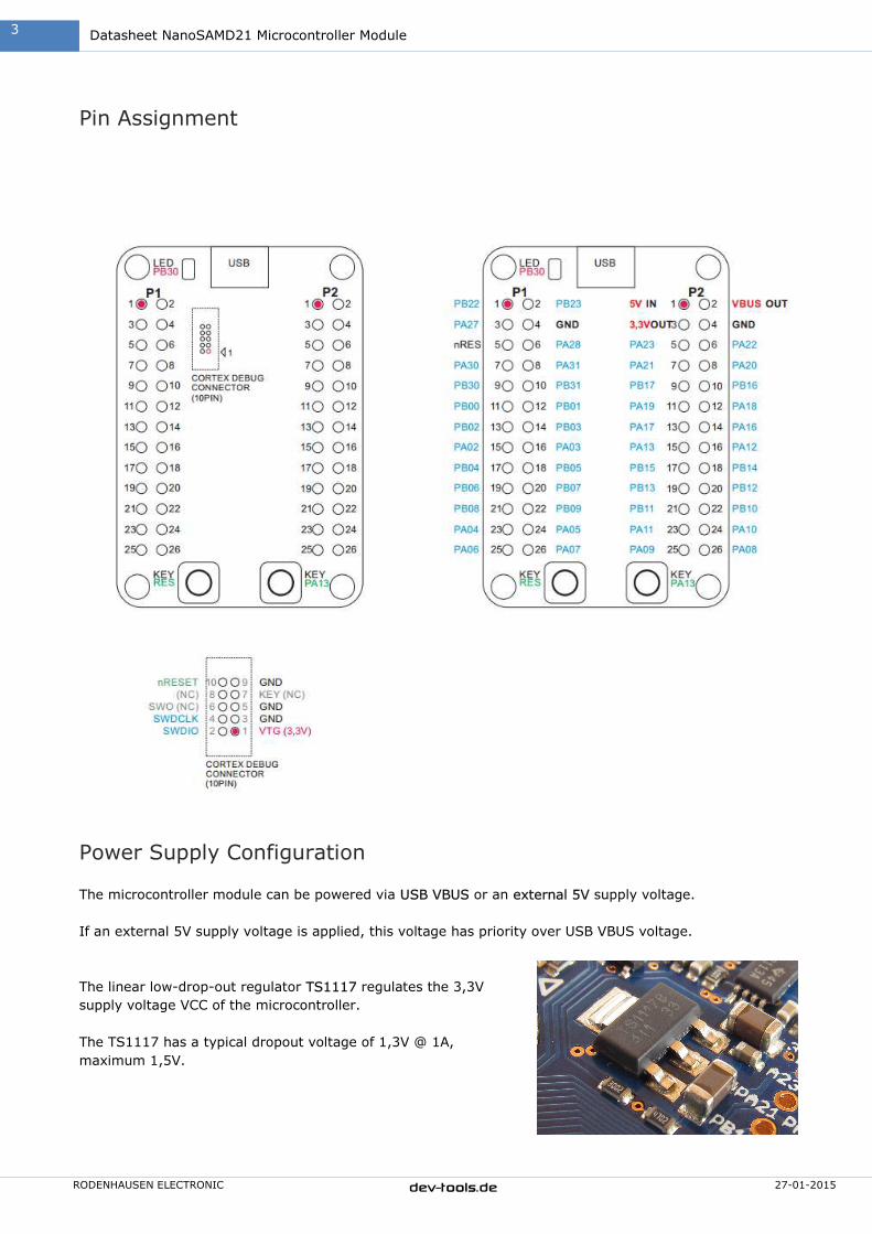
Pin Assignment
Power Supply Configuration
The microcontroller module can be powered via USB VBUS or an external 5V supply voltage.
If an external 5V supply voltage is applied, this voltage has priority over USB VBUS voltage.
The linear low-drop-out regulator TS1117 regulates the 3,3V
supply voltage VCC of the microcontroller.
The TS1117 has a typical dropout voltage of 1,3V @ 1A,
maximum 1,5V.
RODENHAUSEN ELECTRONIC 27-01-2015
4 Datasheet NanoSAMD21 Microcontroller Module
4
dev-tools.de
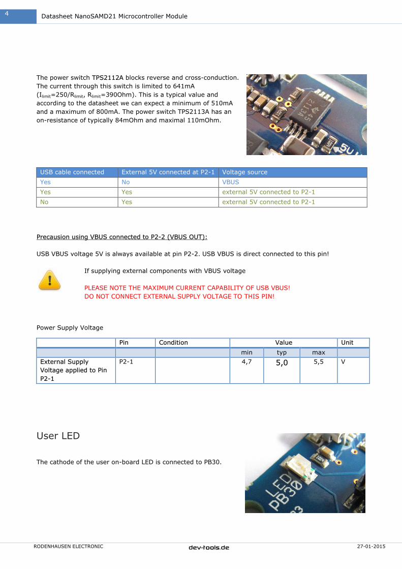
The power switch TPS2112A blocks reverse and cross-conduction.
The current through this switch is limited to 641mA
(Ilimit=250/Rlimit, Rlimit=390Ohm). This is a typical value and
according to the datasheet we can expect a minimum of 510mA
and a maximum of 800mA. The power switch TPS2113A has an
on-resistance of typically 84mOhm and maximal 110mOhm.
USB cable connected External 5V connected at P2-1 Voltage source
Yes No VBUS
Yes Yes external 5V connected to P2-1
No Yes external 5V connected to P2-1
Precausion using VBUS connected to P2-2 (VBUS OUT):
USB VBUS voltage 5V is always available at pin P2-2. USB VBUS is direct connected to this pin!
If supplying external components with VBUS voltage
PLEASE NOTE THE MAXIMUM CURRENT CAPABILITY OF USB VBUS!
DO NOT CONNECT EXTERNAL SUPPLY VOLTAGE TO THIS PIN!
Power Supply Voltage
Pin Condition Value Unit
min typ max
External Supply
Voltage applied to Pin
P2-1
P2-1 4,7 5,0 5,5 V
User LED
The cathode of the user on-board LED is connected to PB30.

RODENHAUSEN ELECTRONIC 27-01-2015
5 Datasheet NanoSAMD21 Microcontroller Module
5
dev-tools.de
User Keys
Press the key RES to reset the microcontroller.
The right user key is connected to PA13. The signal PA13 is set to
low level if key is pressed.
Cortex Debug Connector
Pin Signal
1 VTG 3,3V
2 PA31 SWDIO
3 GND
4 PA30 SWDCLK
5 GND
6 NC (SWO)
7 NC (KEY)
8 NC
9 GND
10 nRESET
Layout
PCB Size 38mm x 44mm,
1,6mm thickness
Design 2 Layers,
SMD Top Layer
Material FR4
Surface Immersion Gold
Soldermask Dev-Tools blue
Silk Skreen White
Panel Processing Milled, Rounded Corners
E-Test Yes
RoHS Yes
RODENHAUSEN ELECTRONIC 27-01-2015
6 Datasheet NanoSAMD21 Microcontroller Module
6
dev-tools.de
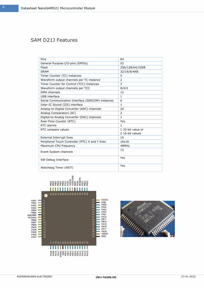
SAM D21J Features
Pins 64
General Purpose I/O-pins (GPIOs) 52
Flash 256/128/64/32KB
SRAM 32/16/8/4KB
Timer Counter (TC) instances 5
Waveform output channels per TC instance 2
Timer Counter for Control (TCC) instances 3
Waveform output channels per TCC 8/4/2
DMA channels 12
USB interface 1
Serial Communication Interface (SERCOM) instances 6
Inter-IC Sound (I2S) interface 1
Analog-to-Digital Converter (ADC) channels 20
Analog Comparators (AC) 2
Digital-to-Analog Converter (DAC) channels 1
Real-Time Counter (RTC) Yes
RTC alarms 1
RTC compare values
1 32-bit value or
2 16-bit values
External Interrupt lines 16
Peripheral Touch Controller (PTC) X and Y lines 16x16
Maximum CPU frequency 48MHz
Event System channels 12
SW Debug Interface Yes
Watchdog Timer (WDT) Yes

RODENHAUSEN ELECTRONIC 27-01-2015
7 Datasheet NanoSAMD21 Microcontroller Module
7
dev-tools.de
Intended use This product is intended to use as development and evaluation board for developing microcontroller based applications.
Warning To avoid damage due to electrostatic discharge (ESD), appropriate measures for ESD protection are to be taken for handling and only
appropriately trained personnel should handle the board.
Disclaimer This product is not authorized for use in safety-critical applications (such as life support) where a failure of this product would reasonably
be expected to cause severe personal injury or death. RODENHAUSEN ELECTRONIC makes no warranty, representation or guarantee
regarding the suitability of its products for any particular purpose, nor does RODENHAUSEN ELECTRONIC assume any liability arising out
of the application or use of any product or circuit, and specifically disclaims any and all liability, including without limitation special,
consequential or incidental damages. “Typical” parameters which may be provided in this documentation and/or specifications can and do
vary in different applications and actual performance may vary over time. All operating parameters, including “Typicals” must be
validated for each customer application by customer’s technical experts. RODENHAUSEN ELECTRONIC reserve the right to make
corrections, modifications, enhancements, improvements, and other changes to this product (including changes of layout, schematic and
documentation) at any time and to discontinue this product without notice. Customers should obtain the latest relevant information
before placing orders and should verify that such information is current and complete.
Note No part of this documentation, including the products and software described in it, may be reproduced, transmitted, transcribed or
translated into any language in any form or by any means, except documentation kept by the purchaser for backup purposes, without
the express written permission of RODENHAUSEN ELECTRONIC. Products and corporate names appearing in this documentation may or
may not be registered trademarks or copyrights of their respective companies, and are used only for identification or explanation and to
the owners’ benefit, without intent to infringe.