Embed Size (px)
Citation preview
Installation ManualMMI-20020984, Rev AB
May 2015
Micro Motion® Specific Gravity Meters (SGM)
Gas specific gravity measurement
Safety and approval information
This Micro Motion product complies with all applicable European directives when properly installed in accordance with theinstructions in this manual. Refer to the EC declaration of conformity for directives that apply to this product. The EC declaration ofconformity, with all applicable European directives, and the complete ATEX Installation Drawings and Instructions are available onthe internet at www.micromotion.com or through your local Micro Motion support center.
Information affixed to equipment that complies with the Pressure Equipment Directive can be found on the internet at www.micromotion.com/documentation.
For hazardous installations in Europe, refer to standard EN 60079-14 if national standards do not apply.
Other information
Full product specifications can be found in the product data sheet. Troubleshooting information can be found in the transmitterconfiguration manual. Product data sheets and manuals are available from the Micro Motion web site at www.micromotion.com/documentation.
Return policy
Micro Motion procedures must be followed when returning equipment. These procedures ensure legal compliance withgovernment transportation agencies and help provide a safe working environment for Micro Motion employees. Failure to followMicro Motion procedures will result in your equipment being refused delivery.
Information on return procedures and forms is available on our web support system at www.micromotion.com, or by phoning theMicro Motion Customer Service department.
Emerson Flow customer service
Email:
• Worldwide: [email protected]
• Asia-Pacific: [email protected]
Telephone:
North and South America Europe and Middle East Asia Pacific
United States 800-522-6277 U.K. 0870 240 1978 Australia 800 158 727
Canada +1 303-527-5200 The Netherlands +31 (0) 704 136 666 New Zealand 099 128 804
Mexico +41 (0) 41 7686 111 France 0800 917 901 India 800 440 1468
Argentina +54 11 4837 7000 Germany 0800 182 5347 Pakistan 888 550 2682
Brazil +55 15 3413 8000 Italy 8008 77334 China +86 21 2892 9000
Venezuela +58 26 1731 3446 Central & Eastern +41 (0) 41 7686 111 Japan +81 3 5769 6803
Russia/CIS +7 495 981 9811 South Korea +82 2 3438 4600
Egypt 0800 000 0015 Singapore +65 6 777 8211
Oman 800 70101 Thailand 001 800 441 6426
Qatar 431 0044 Malaysia 800 814 008
Kuwait 663 299 01
South Africa 800 991 390
Saudi Arabia 800 844 9564
UAE 800 0444 0684
Contents
Chapter 1 Planning ...........................................................................................................................11.1 Installation and commissioning overview ....................................................................................... 11.2 Installation checklist .......................................................................................................................11.3 Best practices ................................................................................................................................. 21.4 Recommended installation for specific gravity applications ........................................................... 31.5 Power requirements .......................................................................................................................4
Chapter 2 Mounting .........................................................................................................................72.1 Mount the meter enclosure to a wall .............................................................................................. 72.2 Connect the gas bypass lines ........................................................................................................102.3 Rotate the display on the transmitter (optional) ...........................................................................11
Chapter 3 Wiring ........................................................................................................................... 133.1 Available output terminals and wiring requirements .................................................................... 133.2 Hazardous area output wiring ...................................................................................................... 13
Chapter 4 Grounding ......................................................................................................................22
Contents
Installation Manual i

Contents
ii Micro Motion Specific Gravity Meters
1 PlanningTopics covered in this chapter:
• Installation and commissioning overview
• Installation checklist
• Best practices
• Recommended installation for specific gravity applications
• Power requirements
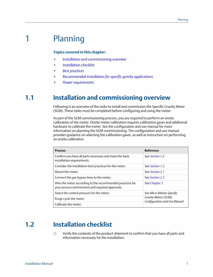
1.1 Installation and commissioning overviewFollowing is an overview of the tasks to install and commission the Specific Gravity Meter(SGM). These tasks must be completed before configuring and using the meter.
As part of the SGM commissioning process, you are required to perform an onsitecalibration of the meter. Onsite meter calibration requires calibration gases and additionalhardware to calibrate the meter. See the configuration and use manual for moreinformation on planning the SGM commissioning. The configuration and use manualprovides guidance on selecting the calibration gases, as well as instruction on performingan onsite calibration.
Process Reference
Confirm you have all parts necessary and meet the basicinstallation requirements.
See Section 1.2
Consider the installation best practices for the meter. See Section 1.3
Mount the meter. See Section 2.1
Connect the gas bypass lines to the meter. See Section 2.2
Wire the meter according to the recommended practices foryour process environment and required approvals.
See Chapter 3
Select the control pressure for the meter. See Micro Motion SpecificGravity Meters (SGM):Configuration and Use Manual
Purge cycle the meter.
Calibrate the meter.
1.2 Installation checklist Verify the contents of the product shipment to confirm that you have all parts and
information necessary for the installation.
Planning
Installation Manual 1
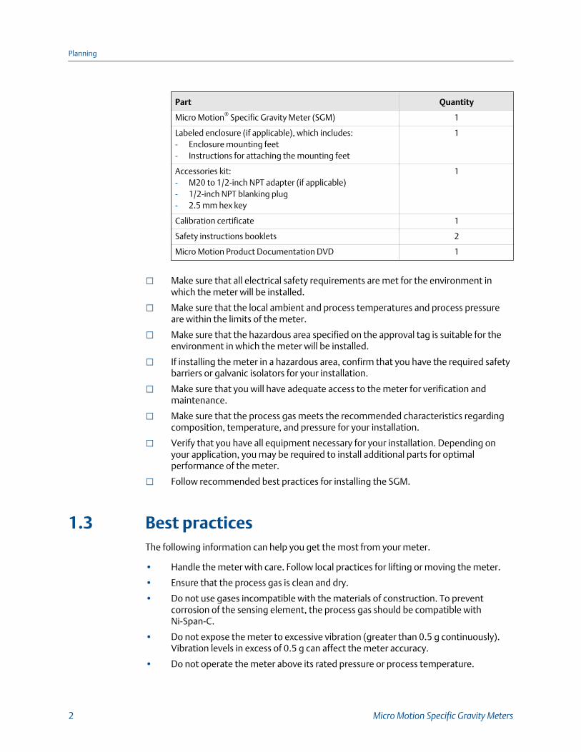
Part Quantity
Micro Motion® Specific Gravity Meter (SGM) 1
Labeled enclosure (if applicable), which includes:- Enclosure mounting feet- Instructions for attaching the mounting feet
1
Accessories kit:- M20 to 1/2-inch NPT adapter (if applicable)- 1/2-inch NPT blanking plug- 2.5 mm hex key
1
Calibration certificate 1
Safety instructions booklets 2
Micro Motion Product Documentation DVD 1
Make sure that all electrical safety requirements are met for the environment inwhich the meter will be installed.
Make sure that the local ambient and process temperatures and process pressureare within the limits of the meter.
Make sure that the hazardous area specified on the approval tag is suitable for theenvironment in which the meter will be installed.
If installing the meter in a hazardous area, confirm that you have the required safetybarriers or galvanic isolators for your installation.
Make sure that you will have adequate access to the meter for verification andmaintenance.
Make sure that the process gas meets the recommended characteristics regardingcomposition, temperature, and pressure for your installation.
Verify that you have all equipment necessary for your installation. Depending onyour application, you may be required to install additional parts for optimalperformance of the meter.
Follow recommended best practices for installing the SGM.
1.3 Best practicesThe following information can help you get the most from your meter.
• Handle the meter with care. Follow local practices for lifting or moving the meter.
• Ensure that the process gas is clean and dry.
• Do not use gases incompatible with the materials of construction. To preventcorrosion of the sensing element, the process gas should be compatible withNi-Span-C.
• Do not expose the meter to excessive vibration (greater than 0.5 g continuously).Vibration levels in excess of 0.5 g can affect the meter accuracy.
• Do not operate the meter above its rated pressure or process temperature.
Planning
2 Micro Motion Specific Gravity Meters
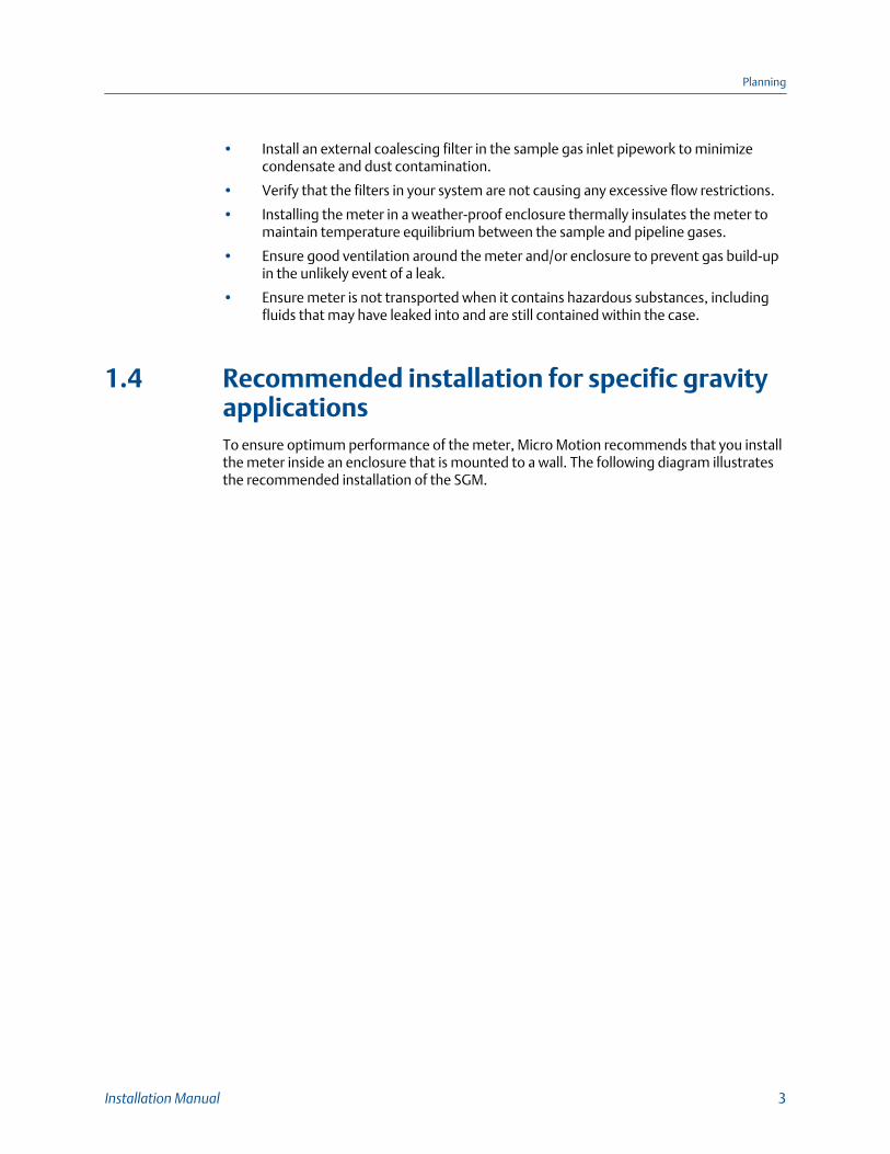
• Install an external coalescing filter in the sample gas inlet pipework to minimizecondensate and dust contamination.
• Verify that the filters in your system are not causing any excessive flow restrictions.
• Installing the meter in a weather-proof enclosure thermally insulates the meter tomaintain temperature equilibrium between the sample and pipeline gases.
• Ensure good ventilation around the meter and/or enclosure to prevent gas build-upin the unlikely event of a leak.
• Ensure meter is not transported when it contains hazardous substances, includingfluids that may have leaked into and are still contained within the case.
1.4 Recommended installation for specific gravityapplicationsTo ensure optimum performance of the meter, Micro Motion recommends that you installthe meter inside an enclosure that is mounted to a wall. The following diagram illustratesthe recommended installation of the SGM.
Planning
Installation Manual 3
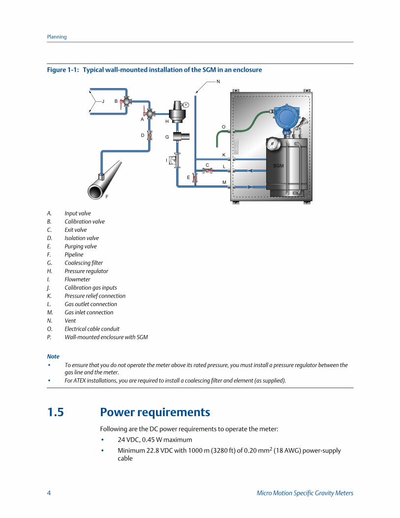
Typical wall-mounted installation of the SGM in an enclosureFigure 1-1:
I
G
E
J B
F
HA
D
C
M
K
L
O
N
SGM
A. Input valveB. Calibration valveC. Exit valveD. Isolation valveE. Purging valveF. PipelineG. Coalescing filterH. Pressure regulatorI. FlowmeterJ. Calibration gas inputsK. Pressure relief connectionL. Gas outlet connectionM. Gas inlet connectionN. VentO. Electrical cable conduitP. Wall-mounted enclosure with SGM
Note• To ensure that you do not operate the meter above its rated pressure, you must install a pressure regulator between the
gas line and the meter.• For ATEX installations, you are required to install a coalescing filter and element (as supplied).
1.5 Power requirementsFollowing are the DC power requirements to operate the meter:
• 24 VDC, 0.45 W maximum
• Minimum 22.8 VDC with 1000 m (3280 ft) of 0.20 mm2 (18 AWG) power-supplycable
Planning
4 Micro Motion Specific Gravity Meters
• At startup, power source must provide a minimum of 0.5 A of short-term current ata minimum of 19.6 V at the power-input terminals.
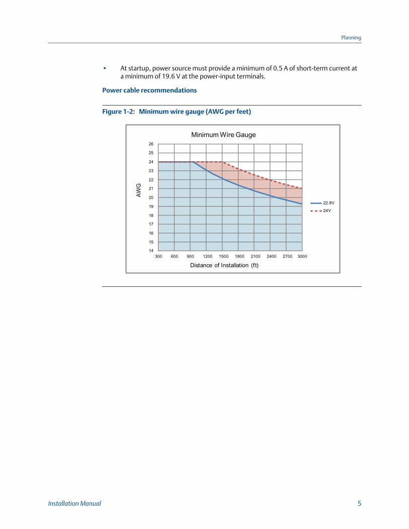
Power cable recommendations
Minimum wire gauge (AWG per feet)Figure 1-2:
300 600 900 1200 1500 1800 2100 2400 2700 3000
Distance of Installation (ft)
22.8V
24V
14
15
16
17
18
19
20
21
22
23
24
25
26AW
GMinimum Wire Gauge
Planning
Installation Manual 5
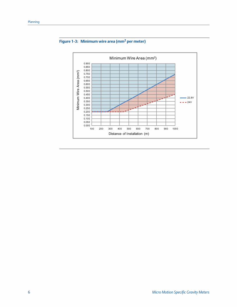
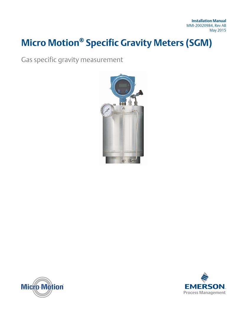
Minimum wire area (mm2 per meter)Figure 1-3:
0.0000.0500.1000.1500.2000.2500.3000.3500.4000.4500.5000.5500.6000.6500.7000.7500.8000.8500.900
100 200 300 400 500 600 700 800 900 1000
Min
imum
Wire
Are
a (m
m2 )
Distance of Installation (m)
Minimum Wire Area (mm2)
22.8V
24V
Planning
6 Micro Motion Specific Gravity Meters
2 MountingTopics covered in this chapter:
• Mount the meter enclosure to a wall
• Connect the gas bypass lines
• Rotate the display on the transmitter (optional)
2.1 Mount the meter enclosure to a wallMicro Motion recommends that you install the meter in an enclosure that is mounted to awall.
When you order the meter with an enclosure, the meter and pipework inside the enclosureare configured at the factory to allow for easy installation of the meter in your processpipeline.
ImportantIf you are installing the SGM as a stand-alone device (not inside an enclosure): for best performance,you must ensure that the SGM is not exposed to rapid changes in temperature.
Mounting
Installation Manual 7
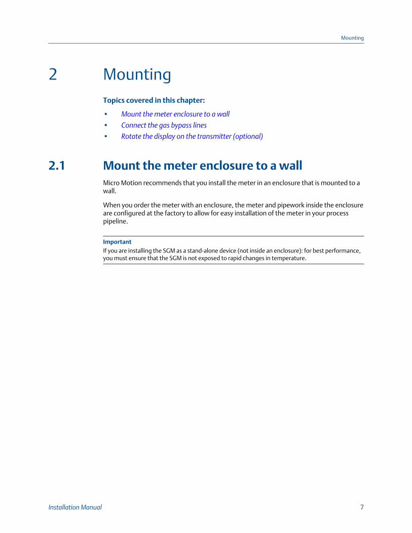
SGM installed in mounting enclosureFigure 2-1:
A
B
A. Thermally insulating enclosure with external connectors for gas and pressure reliefB. SGM with internal pipework to external connectors
Procedure
1. Attach the mounting brackets to the exterior of the meter enclosure. All necessaryparts and instructions for attaching the feet are shipped with the product.
2. Prepare the mounting location on the wall. See Section 2.1.1 and Section 2.1.2 for themounting dimensions of the small and large enclosures.
3. Attach the meter enclosure to the wall-mount location.
CAUTION!
When lifting or transporting the meter inside the enclosure, be sure not to drop themeter. While the meter enclosure is designed to minimize damage due to shocks,dropping the meter will damage the meter.
Mounting
8 Micro Motion Specific Gravity Meters
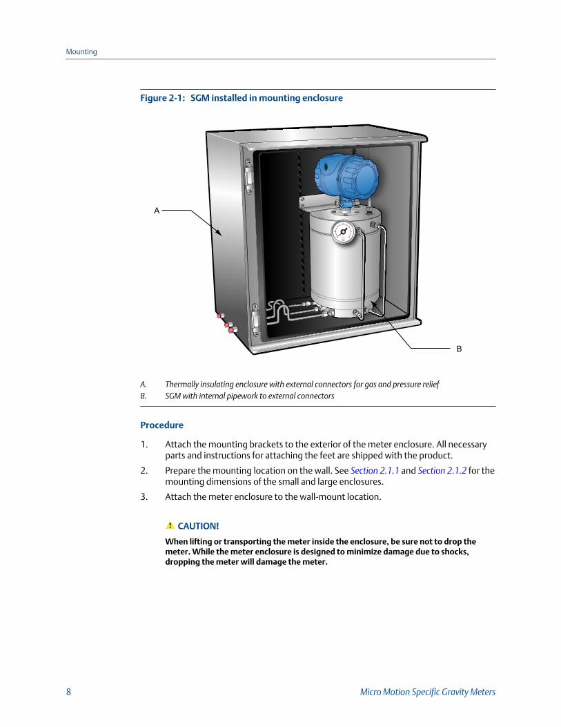
2.1.1 Mounting dimensions for small enclosure
Mounting dimensions for small enclosureFigure 2-2:
19.69"(500mm)
19.72"(501mm)
20.2"(513mm)
16.88"(429mm)
TOP
TOP12"
(305mm)
20.32"(516mm)
17.1"(423mm)
Ø.33"(8.5mm)
1.2"(30mm)
Mounting
Installation Manual 9
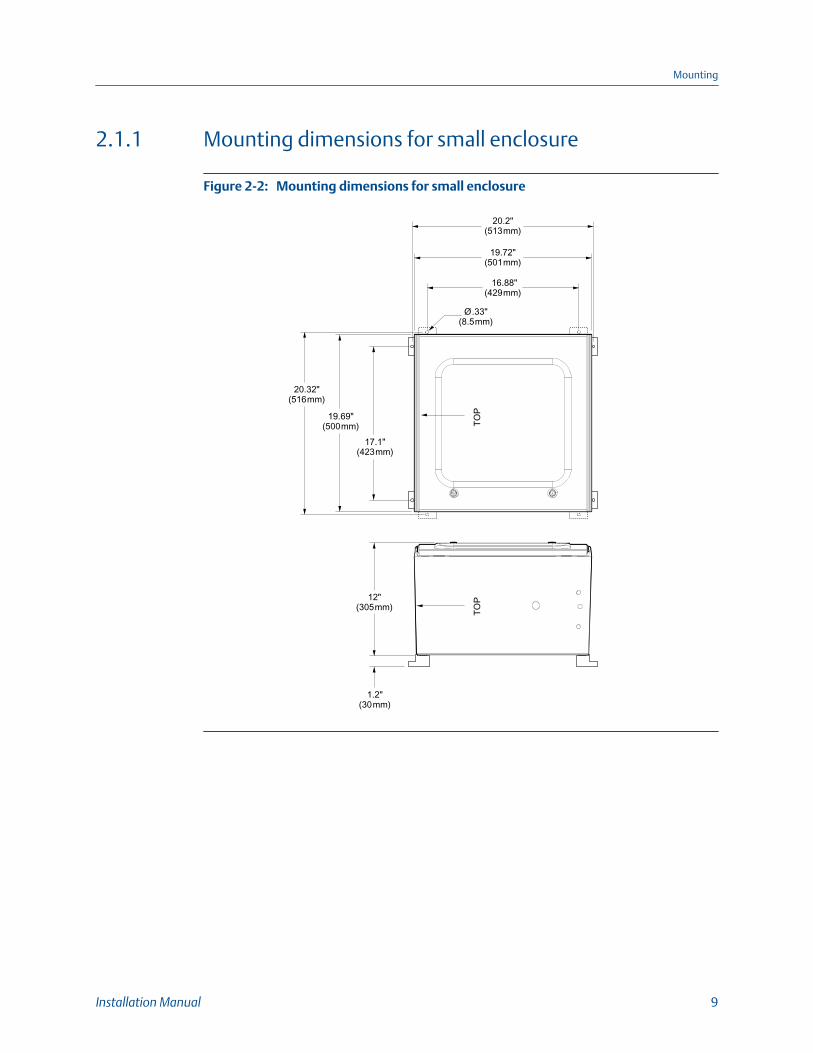
2.1.2 Mounting dimensions for large enclosure
Mounting dimensions for large enclosureFigure 2-3:
20.6"(523 mm)
31.5"(800mm)
32.1"(816mm)
28.5"(723mm)
24.3"(616 mm)
23.6"(600mm)
Ø.33"(8.5mm)
12"(305mm)
1.2"(30mm)
TOP
TOP
2.2 Connect the gas bypass linesOnce you have mounted the meter, you are ready to connect the gas bypass lines. Thereare three lines: sample gas input, sample gas output, and pressure relief.
Each connector is a 1/4-inch Swagelok bulkhead fitting. These connectors are located onthe outside of the enclosure.
Mounting
10 Micro Motion Specific Gravity Meters
Procedure
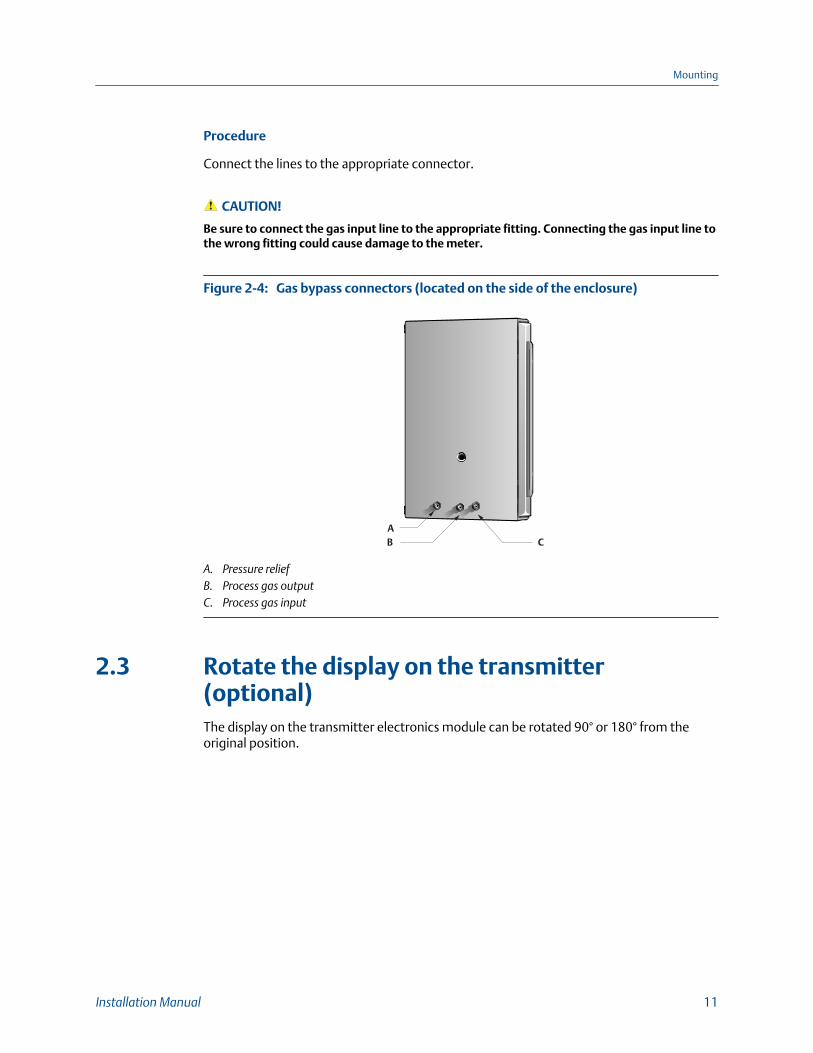
Connect the lines to the appropriate connector.
CAUTION!
Be sure to connect the gas input line to the appropriate fitting. Connecting the gas input line tothe wrong fitting could cause damage to the meter.
Gas bypass connectors (located on the side of the enclosure)Figure 2-4:
ACB
A. Pressure reliefB. Process gas outputC. Process gas input
2.3 Rotate the display on the transmitter(optional)The display on the transmitter electronics module can be rotated 90° or 180° from theoriginal position.
Mounting
Installation Manual 11
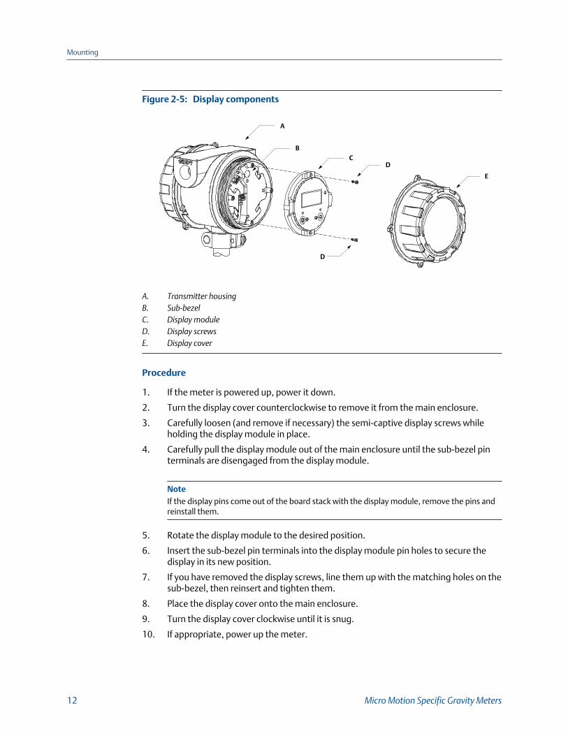
Display componentsFigure 2-5:
BC
D
A
D
E
A. Transmitter housingB. Sub-bezelC. Display moduleD. Display screwsE. Display cover
Procedure
1. If the meter is powered up, power it down.
2. Turn the display cover counterclockwise to remove it from the main enclosure.
3. Carefully loosen (and remove if necessary) the semi-captive display screws whileholding the display module in place.
4. Carefully pull the display module out of the main enclosure until the sub-bezel pinterminals are disengaged from the display module.
NoteIf the display pins come out of the board stack with the display module, remove the pins andreinstall them.
5. Rotate the display module to the desired position.
6. Insert the sub-bezel pin terminals into the display module pin holes to secure thedisplay in its new position.
7. If you have removed the display screws, line them up with the matching holes on thesub-bezel, then reinsert and tighten them.
8. Place the display cover onto the main enclosure.
9. Turn the display cover clockwise until it is snug.
10. If appropriate, power up the meter.
Mounting
12 Micro Motion Specific Gravity Meters
3 WiringTopics covered in this chapter:
• Available output terminals and wiring requirements
• Hazardous area output wiring
3.1 Available output terminals and wiringrequirementsThree pairs of wiring terminals are available for transmitter outputs. These outputs varydepending on your transmitter output option ordered. The Analog (mA), Time PeriodSignal (TPS), and Discrete (DO) outputs require external power, and must be connected toan independent 24 VDC power supply.
The screw connectors for each output terminal accept a maximum wire size of 14 AWG(2.5 mm2).
Important
• Output wiring requirements depend on the hazardous area classification of the environmentin which the meter is installed. It is your responsibility to verify that this installation meets allcorporate, local, and national safety requirements and electrical codes.
• If you will configure the meter to poll an external temperature or pressure device, you mustwire the mA output to support HART communications. You may use either HART/mA single-loop wiring or HART multi-drop wiring.
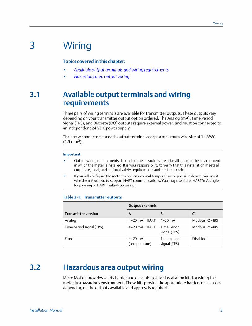
Transmitter outputsTable 3-1:
Transmitter version
Output channels
A B C
Analog 4–20 mA + HART 4–20 mA Modbus/RS-485
Time period signal (TPS) 4–20 mA + HART Time PeriodSignal (TPS)
Modbus/RS-485
Fixed 4–20 mA(temperature)
Time periodsignal (TPS)
Disabled
3.2 Hazardous area output wiringMicro Motion provides safety barrier and galvanic isolator installation kits for wiring themeter in a hazardous environment. These kits provide the appropriate barriers or isolatorsdepending on the outputs available and approvals required.
Wiring
Installation Manual 13
Information provided about wiring the safety barriers and galvanic isolators is intended asan overview. You should wire the meter according to the standards that are applicable atyour site.
CAUTION!
• Meter installation and wiring should be performed by suitably trained personnel only inaccordance with the applicable code of practice.
• Refer to the hazardous area approvals documentation shipped with your meter. Safetyinstructions are available on the Micro Motion Product Documentation DVD andaccessible on the Micro Motion website at www.micromotion.com.
3.2.1 Hazardous area entity parameters
DANGER!
Hazardous voltage can cause severe injury or death. To reduce the risk of hazardous voltage,shut off power before wiring the meter.
DANGER!
Improper wiring in a hazardous environment can cause an explosion. Install the meter only inan area that complies with the hazardous classification tag on the meter.
Input entity parameters
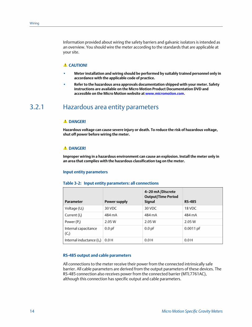
Input entity parameters: all connectionsTable 3-2:
Parameter Power supply
4–20 mA /DiscreteOutput/Time PeriodSignal RS-485
Voltage (Ui) 30 VDC 30 VDC 18 VDC
Current (Ii) 484 mA 484 mA 484 mA
Power (Pi) 2.05 W 2.05 W 2.05 W
Internal capacitance(Ci)
0.0 pF 0.0 pF 0.0011 pF
Internal inductance (Li) 0.0 H 0.0 H 0.0 H
RS-485 output and cable parameters
All connections to the meter receive their power from the connected intrinsically safebarrier. All cable parameters are derived from the output parameters of these devices. TheRS-485 connection also receives power from the connected barrier (MTL7761AC),although this connection has specific output and cable parameters.
Wiring
14 Micro Motion Specific Gravity Meters
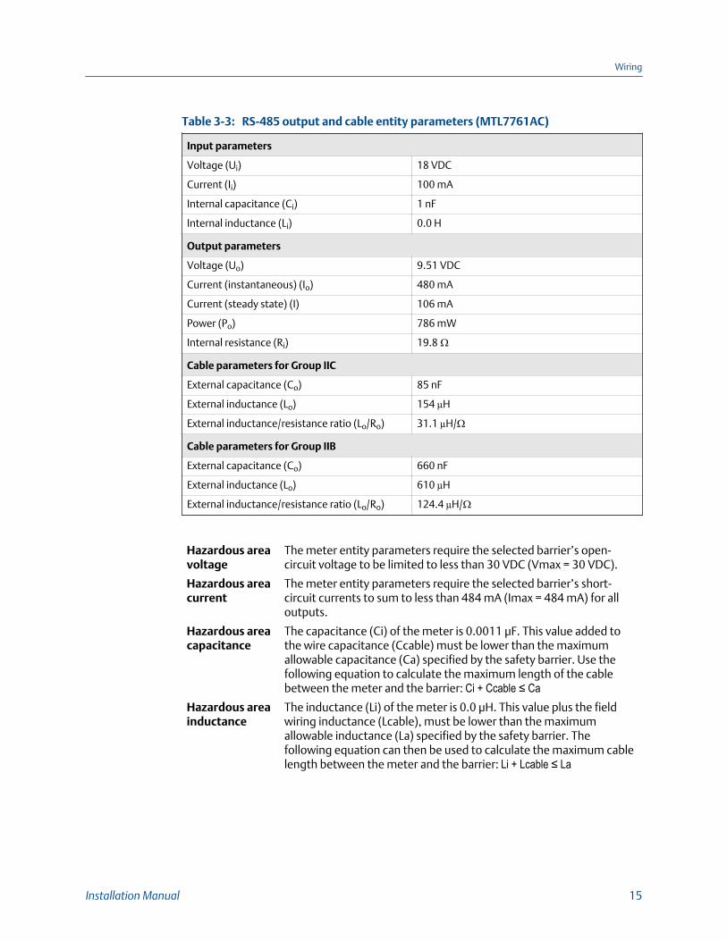
RS-485 output and cable entity parameters (MTL7761AC)Table 3-3:
Input parameters
Voltage (Ui) 18 VDC
Current (Ii) 100 mA
Internal capacitance (Ci) 1 nF
Internal inductance (Li) 0.0 H
Output parameters
Voltage (Uo) 9.51 VDC
Current (instantaneous) (Io) 480 mA
Current (steady state) (I) 106 mA
Power (Po) 786 mW
Internal resistance (Ri) 19.8 Ω
Cable parameters for Group IIC
External capacitance (Co) 85 nF
External inductance (Lo) 154 µH
External inductance/resistance ratio (Lo/Ro) 31.1 µH/Ω
Cable parameters for Group IIB
External capacitance (Co) 660 nF
External inductance (Lo) 610 µH
External inductance/resistance ratio (Lo/Ro) 124.4 µH/Ω
Hazardous areavoltage
The meter entity parameters require the selected barrier’s open-circuit voltage to be limited to less than 30 VDC (Vmax = 30 VDC).
Hazardous areacurrent
The meter entity parameters require the selected barrier’s short-circuit currents to sum to less than 484 mA (Imax = 484 mA) for alloutputs.
Hazardous areacapacitance
The capacitance (Ci) of the meter is 0.0011 μF. This value added tothe wire capacitance (Ccable) must be lower than the maximumallowable capacitance (Ca) specified by the safety barrier. Use thefollowing equation to calculate the maximum length of the cablebetween the meter and the barrier: Ci + Ccable ≤ Ca
Hazardous areainductance
The inductance (Li) of the meter is 0.0 μH. This value plus the fieldwiring inductance (Lcable), must be lower than the maximumallowable inductance (La) specified by the safety barrier. Thefollowing equation can then be used to calculate the maximum cablelength between the meter and the barrier: Li + Lcable ≤ La
Wiring
Installation Manual 15
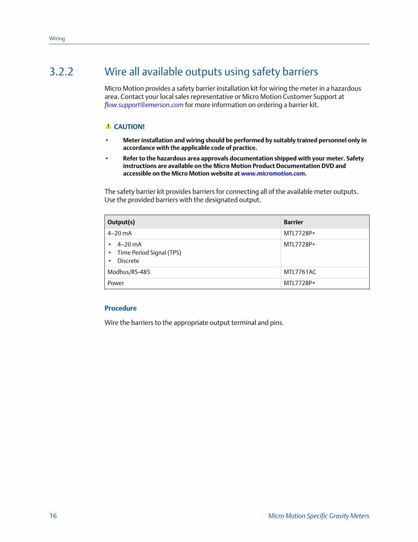
3.2.2 Wire all available outputs using safety barriersMicro Motion provides a safety barrier installation kit for wiring the meter in a hazardousarea. Contact your local sales representative or Micro Motion Customer Support at [email protected] for more information on ordering a barrier kit.
CAUTION!
• Meter installation and wiring should be performed by suitably trained personnel only inaccordance with the applicable code of practice.
• Refer to the hazardous area approvals documentation shipped with your meter. Safetyinstructions are available on the Micro Motion Product Documentation DVD andaccessible on the Micro Motion website at www.micromotion.com.
The safety barrier kit provides barriers for connecting all of the available meter outputs.Use the provided barriers with the designated output.
Output(s) Barrier
4–20 mA MTL7728P+
• 4–20 mA• Time Period Signal (TPS)• Discrete
MTL7728P+
Modbus/RS-485 MTL7761AC
Power MTL7728P+
Procedure
Wire the barriers to the appropriate output terminal and pins.
Wiring
16 Micro Motion Specific Gravity Meters
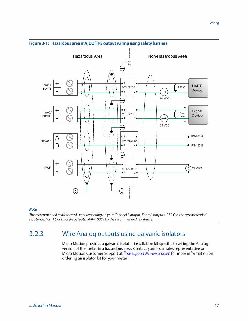
Hazardous area mA/DO/TPS output wiring using safety barriersFigure 3-1:
Bus Bar
Hazardous Area Non-Hazardous Area
MTL7761AC
RS-485 A
RS-485 B
3
4
1
2
24 VDC
24 VDC
MTL7728P+
24 VDC
3
4
1
2
MTL7728P+3
4
1
2
250 ΩMTL7728P+3
4
1
2
HARTDevice
SignalDevice
Seenote
mA1+HART
RS-485
PWR
mA2/TPS/DO
AB
NoteThe recommended resistance will vary depending on your Channel B output. For mA outputs, 250 Ω is the recommendedresistance. For TPS or Discrete outputs, 500–1000 Ω is the recommended resistance.
3.2.3 Wire Analog outputs using galvanic isolatorsMicro Motion provides a galvanic isolator installation kit specific to wiring the Analogversion of the meter in a hazardous area. Contact your local sales representative orMicro Motion Customer Support at [email protected] for more information onordering an isolator kit for your meter.
Wiring
Installation Manual 17
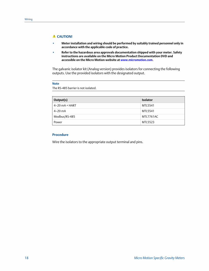
CAUTION!
• Meter installation and wiring should be performed by suitably trained personnel only inaccordance with the applicable code of practice.
• Refer to the hazardous area approvals documentation shipped with your meter. Safetyinstructions are available on the Micro Motion Product Documentation DVD andaccessible on the Micro Motion website at www.micromotion.com.
The galvanic isolator kit (Analog version) provides isolators for connecting the followingoutputs. Use the provided isolators with the designated output.
NoteThe RS-485 barrier is not isolated.
Output(s) Isolator
4–20 mA + HART MTL5541
4–20 mA MTL5541
Modbus/RS-485 MTL7761AC
Power MTL5523
Procedure
Wire the isolators to the appropriate output terminal and pins.
Wiring
18 Micro Motion Specific Gravity Meters
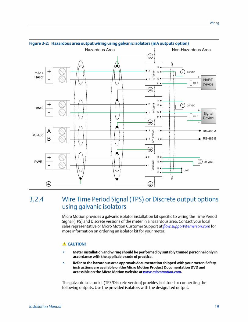
Hazardous area output wiring using galvanic isolators (mA outputs option)Figure 3-2:
mA1+HART
RS-485
PWR
mA2
Hazardous Area Non-Hazardous Area
MTL
7761
AC RS-485 A
RS-485 B
3
4
1
2
MTL
55412
1
14
13
12
11
MTL
5523
2
1
24 VDC
14
13
1211
24 VDC
LINK
250 Ω
MTL
55412
1
14
13
12
11
24 VDC
250 Ω
AB
HARTDevice
SignalDevice
3.2.4 Wire Time Period Signal (TPS) or Discrete output optionsusing galvanic isolatorsMicro Motion provides a galvanic isolator installation kit specific to wiring the Time PeriodSignal (TPS) and Discrete versions of the meter in a hazardous area. Contact your localsales representative or Micro Motion Customer Support at [email protected] formore information on ordering an isolator kit for your meter.
CAUTION!
• Meter installation and wiring should be performed by suitably trained personnel only inaccordance with the applicable code of practice.
• Refer to the hazardous area approvals documentation shipped with your meter. Safetyinstructions are available on the Micro Motion Product Documentation DVD andaccessible on the Micro Motion website at www.micromotion.com.
The galvanic isolator kit (TPS/Discrete version) provides isolators for connecting thefollowing outputs. Use the provided isolators with the designated output.
Wiring
Installation Manual 19
NoteThe RS-485 barrier is not isolated.
Output(s) Isolator
4–20 mA + HART MTL5541
• Time Period Signal (TPS)• Discrete
MTL5532
Modbus/RS-485 MTL7761AC
Power MTL5523
Procedure
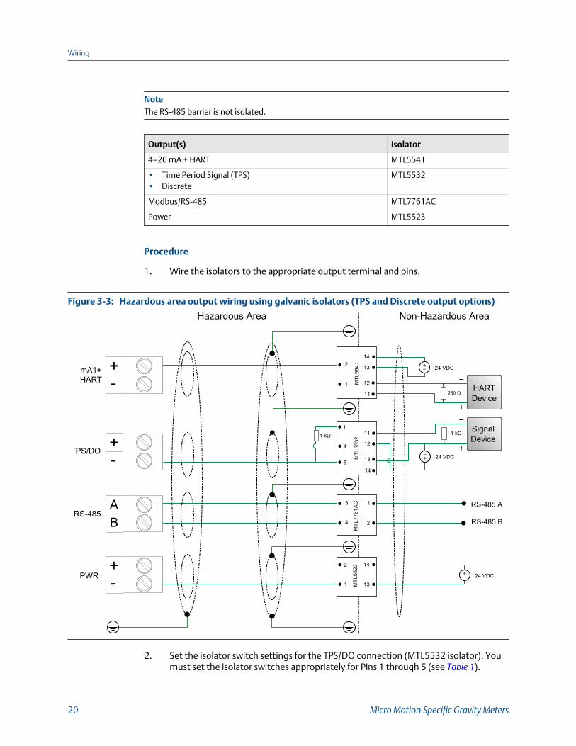
1. Wire the isolators to the appropriate output terminal and pins.
Hazardous area output wiring using galvanic isolators (TPS and Discrete output options)Figure 3-3:
TPS/DO
mA1+HART
RS-485
PWR
SIG
Hazardous Area Non-Hazardous Area
MTL
7761
ACM
TL55
32
RS-485 A
RS-485 B
5
3
4
1
2
111
12
13
14
4
1 kΩ
MTL
55412
1
14
13
12
11
MTL
55232
1
24 VDC
24 VDC
14
1324 VDC
1 kΩ
250 Ω
AB
HARTDevice
SignalDevice
2. Set the isolator switch settings for the TPS/DO connection (MTL5532 isolator). Youmust set the isolator switches appropriately for Pins 1 through 5 (see Table 1).
Wiring
20 Micro Motion Specific Gravity Meters
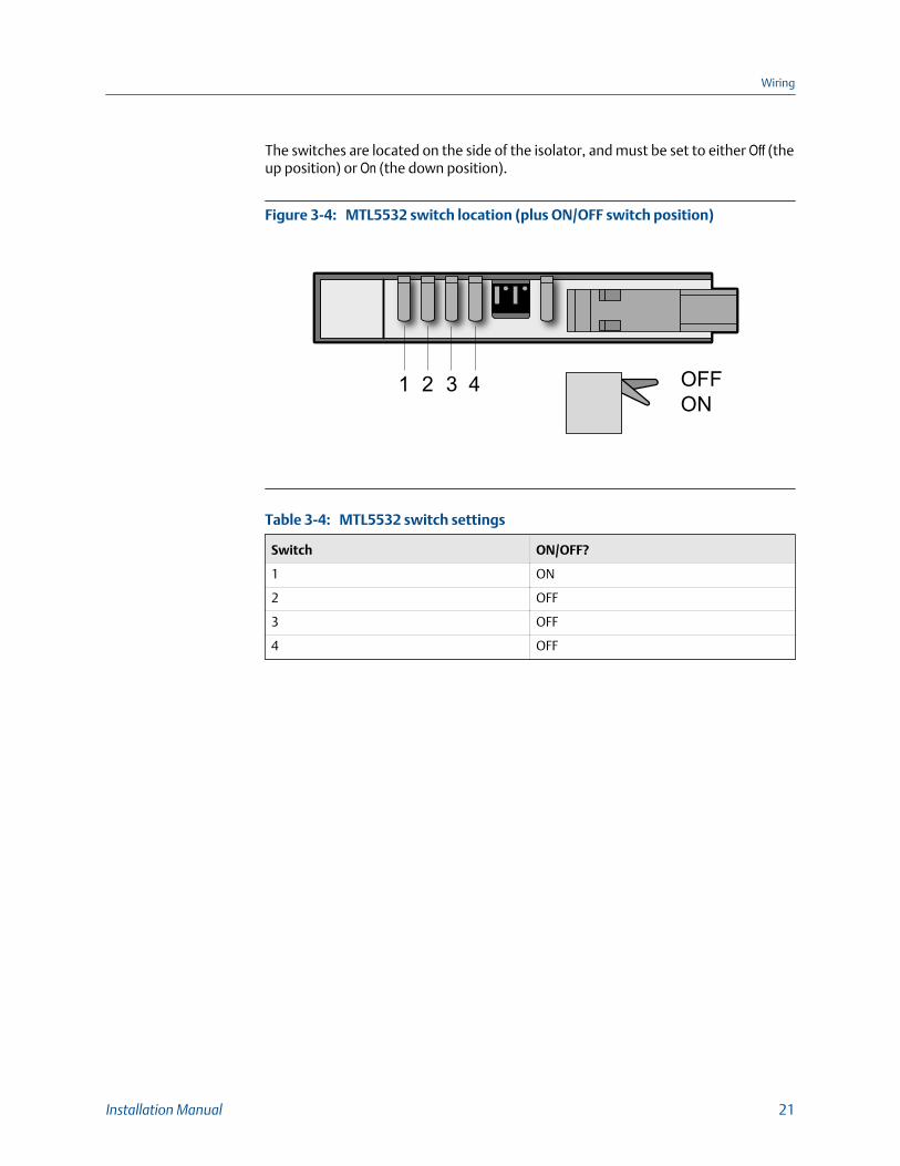
The switches are located on the side of the isolator, and must be set to either Off (theup position) or On (the down position).
MTL5532 switch location (plus ON/OFF switch position)Figure 3-4:
1 2 3 4 OFFON
MTL5532 switch settingsTable 3-4:
Switch ON/OFF?
1 ON
2 OFF
3 OFF
4 OFF
Wiring
Installation Manual 21
4 Grounding
The meter must be grounded according to the standards that are applicable at the site.The customer is responsible for knowing and complying with all applicable standards.
Prerequisites
Micro Motion suggests the following guides for grounding practices:
• In Europe, EN 60079-14 is applicable to most installations, in particular Sections12.2.2.3 and 12.2.2.4.
• In the U.S.A. and Canada, ISA 12.06.01 Part 1 provides examples with associatedapplications and requirements.
• For IECEx installations, IEC 60079-14 is applicable.
If no external standards are applicable, follow these guidelines to ground the meter:
• Use copper wire, 18 AWG (0.75 mm2) or larger wire size.
• Keep all ground leads as short as possible, less than 1 Ω impedance.
• Connect ground leads directly to earth, or follow plant standards.
CAUTION!
Ground the meter to earth, or follow ground network requirements for the facility. Impropergrounding can cause measurement error.
Procedure
Check the joints in the pipeline.
- If the joints in the pipeline are ground-bonded, the sensor is automatically groundedand no further action is necessary (unless required by local code).
- If the joints in the pipeline are not grounded, connect a ground wire to the groundingscrew located on the sensor electronics.
Grounding
22 Micro Motion Specific Gravity Meters

Grounding
Installation Manual 23

*MMI-20020984*MMI-20020984
Rev AB
2015
Micro Motion Inc. USAWorldwide Headquarters7070 Winchester CircleBoulder, Colorado 80301T +1 303-527-5200T +1 800-522-6277F +1 303-530-8459www.micromotion.com
Micro Motion EuropeEmerson Process ManagementNeonstraat 16718 WX EdeThe NetherlandsT +31 (0) 70 413 6666F +31 (0) 318 495 556www.micromotion.nl
Micro Motion AsiaEmerson Process Management1 Pandan CrescentSingapore 128461Republic of SingaporeT +65 6777-8211F +65 6770-8003
Micro Motion United KingdomEmerson Process Management LimitedHorsfield WayBredbury Industrial EstateStockport SK6 2SU U.K.T +44 0870 240 1978F +44 0800 966 181
Micro Motion JapanEmerson Process Management1-2-5, Higashi ShinagawaShinagawa-kuTokyo 140-0002 JapanT +81 3 5769-6803F +81 3 5769-6844
©2015 Micro Motion, Inc. All rights reserved.
The Emerson logo is a trademark and service mark of EmersonElectric Co. Micro Motion, ELITE, ProLink, MVD and MVD DirectConnect marks are marks of one of the Emerson ProcessManagement family of companies. All other marks are property oftheir respective owners.