Embed Size (px)
Citation preview
Installation Manual20001008, Rev BA
February 2015
Micro Motion® Model 3700 Transmitter (MVD) or Model 3350 Peripheral
Installation manual for field mount
Safety and approval information
This Micro Motion product complies with all applicable European directives when properly installed in accordance with the instructions in this manual. Refer to the EC declaration of conformity for directives that apply to this product. The EC declaration of conformity, with all applicable European directives, and the complete ATEX Installation Drawings and Instructions are available on the internet at www.micromotion.com or through your local Micro Motion support center.
Information affixed to equipment that complies with the Pressure Equipment Directive can be found on the internet at www.micromotion.com/documentation.
For hazardous installations in Europe, refer to standard EN 60079-14 if national standards do not apply.
Other information
Full product specifications can be found in the product data sheet. Troubleshooting information can be found in the transmitter configuration manual. Product data sheets and manuals are available from the Micro Motion web site at www.micromotion.com/documentation.
Return policy
Micro Motion procedures must be followed when returning equipment. These procedures ensure legal compliance with government transportation agencies and help provide a safe working environment for Micro Motion employees. Failure to follow Micro Motion procedures will result in your equipment being refused delivery.
Information on return procedures and forms are available on our web support system at www.micromotion.com, or by phoning the Micro Motion Customer Service department.
Emerson Flow customer service
Email:
• Worldwide: [email protected]• Asia-Pacific: [email protected]
Telephone:
North and South America Europe and Middle East Asia Pacific
United States 800-522-6277 U.K. 0870 240 1978 Australia 800 158 727
Canada +1 303-527-5200 The Netherlands +31 (0) 704 136 666 New Zealand 099 128 804
Mexico +41 (0) 41 7686 111 France 0800917901 India 800 440 1468
Argentina +54 11 4837 7000 Germany 0800 182 5347 Pakistan 888 550 2682
Brazil +55 15 3413 8000 Italy 8008 77334 China +86 21 2892 9000
Venezuela +58 26 1731 3446 Central & Eastern +41 (0) 41 7686 111 Japan +81 3 5769 6803
Russia/CIS +7 495 981 9811 South Korea +82 2 3438 4600
Egypt 0800 000 0015 Singapore +65 6 777 8211
Oman 800 70101 Thailand 001 800 441 6426
Qatar 431 0044 Malaysia 800 814 008
Kuwait 663 299 01
South Africa 800 991 390
Saudia Arabia 800 844 9564
UAE 800 0444 0684
Installation Manual 3
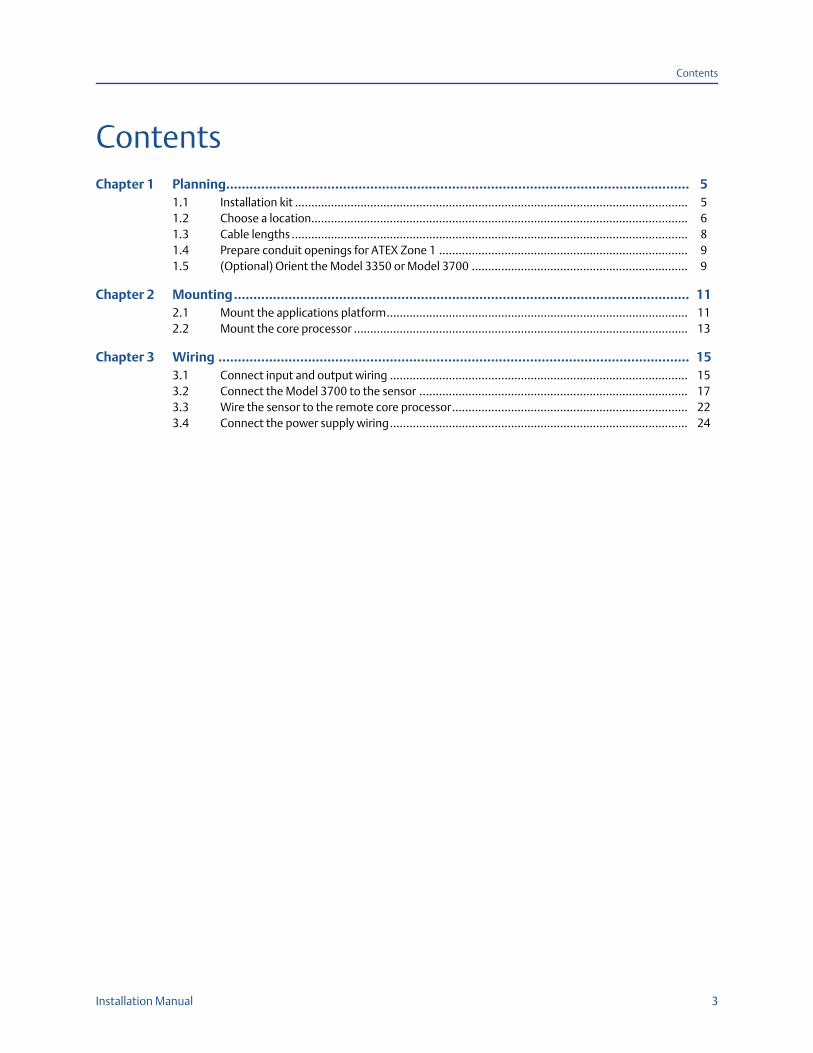
Contents
ContentsChapter 1 Planning....................................................................................................................... 5
1.1 Installation kit ........................................................................................................................ 51.2 Choose a location................................................................................................................... 61.3 Cable lengths ......................................................................................................................... 81.4 Prepare conduit openings for ATEX Zone 1 ............................................................................ 91.5 (Optional) Orient the Model 3350 or Model 3700 .................................................................. 9
Chapter 2 Mounting..................................................................................................................... 112.1 Mount the applications platform............................................................................................ 112.2 Mount the core processor ...................................................................................................... 13
Chapter 3 Wiring ......................................................................................................................... 153.1 Connect input and output wiring ........................................................................................... 153.2 Connect the Model 3700 to the sensor .................................................................................. 173.3 Wire the sensor to the remote core processor........................................................................ 223.4 Connect the power supply wiring........................................................................................... 24

4 Model 3700 Transmitters or Model 3350 Peripherals - Field Mount
Installation Manual 5
Planning
1 PlanningThis installation manual explains basic installation guidelines for installing the Micro Motion Model 3350 or Model 3700 MVD applications platform.
For information on I.S. applications, refer to Micro Motion approval documentation.
For complete instructions about configuration, maintenance, and service, refer to the instruction manual shipped with the transmitter.
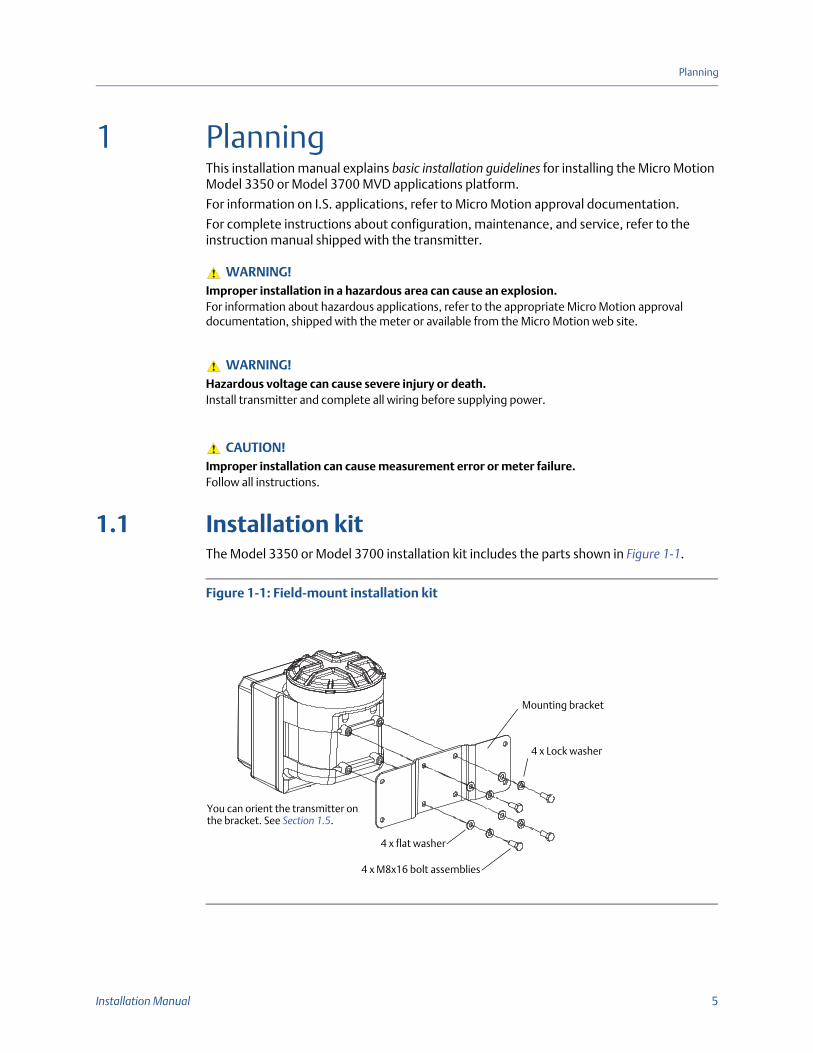
1.1 Installation kitThe Model 3350 or Model 3700 installation kit includes the parts shown in Figure 1-1.
Figure 1-1: Field-mount installation kit
WARNING!Improper installation in a hazardous area can cause an explosion. For information about hazardous applications, refer to the appropriate Micro Motion approval documentation, shipped with the meter or available from the Micro Motion web site.
WARNING!Hazardous voltage can cause severe injury or death.Install transmitter and complete all wiring before supplying power.
CAUTION!Improper installation can cause measurement error or meter failure.Follow all instructions.
4 x flat washer
4 x Lock washer
4 x M8x16 bolt assemblies
Mounting bracket
You can orient the transmitter on the bracket. See Section 1.5.
6 Model 3700 Transmitters or Model 3350 Peripherals - Field Mount
Planning
1.2 Choose a locationChoose a location for the transmitter based on the requirements described below.
1.2.1 Environmental requirementsInstall the Model 3350 or Model 3700 where the ambient temperature is between –4 to +140 °F (–20 to +60 °C).
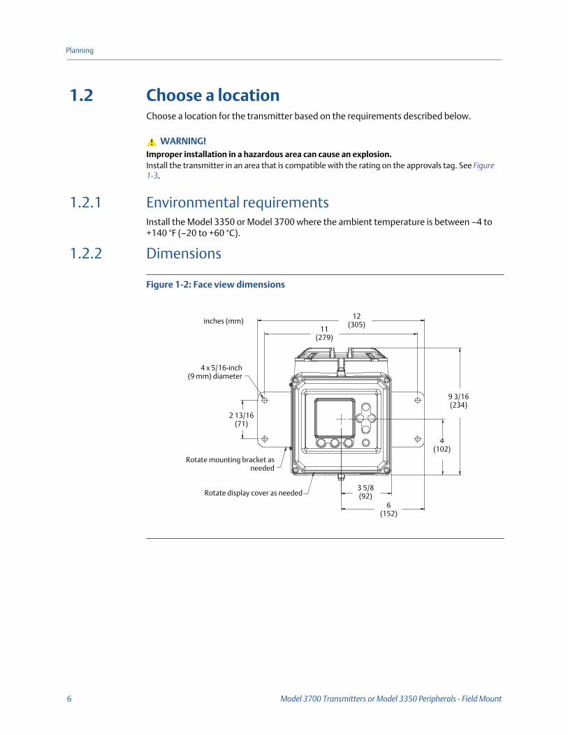
1.2.2 Dimensions
Figure 1-2: Face view dimensions
WARNING!Improper installation in a hazardous area can cause an explosion. Install the transmitter in an area that is compatible with the rating on the approvals tag. See Figure 1-3.
inches (mm)
Rotate display cover as needed
Rotate mounting bracket asneeded
2 13/16(71)
4 x 5/16-inch(9 mm) diameter
9 3/16(234)
4(102)
3 5/8(92)
6(152)
11(279)
12(305)
Installation Manual 7
Planning
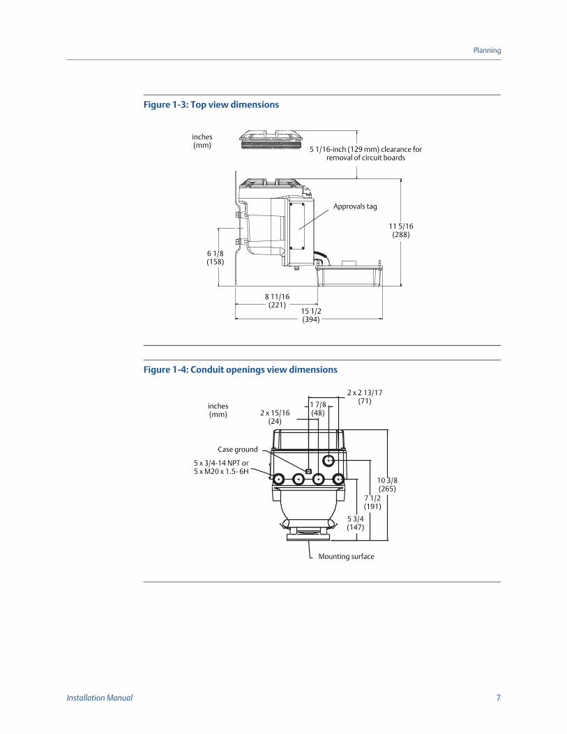
Figure 1-3: Top view dimensions
Figure 1-4: Conduit openings view dimensions
Approvals tag
5 1/16-inch (129 mm) clearance for removal of circuit boards
inches(mm)
11 5/16(288)
6 1/8(158)
15 1/2(394)
8 11/16(221)
5 x 3/4-14 NPT or5 x M20 x 1.5- 6H
Case ground
Mounting surface
inches(mm) 2 x 15/16
(24)
1 7/8(48)
2 x 2 13/17(71)
10 3/8(265)
7 1/2(191)
5 3/4(147)
8 Model 3700 Transmitters or Model 3350 Peripherals - Field Mount
Planning
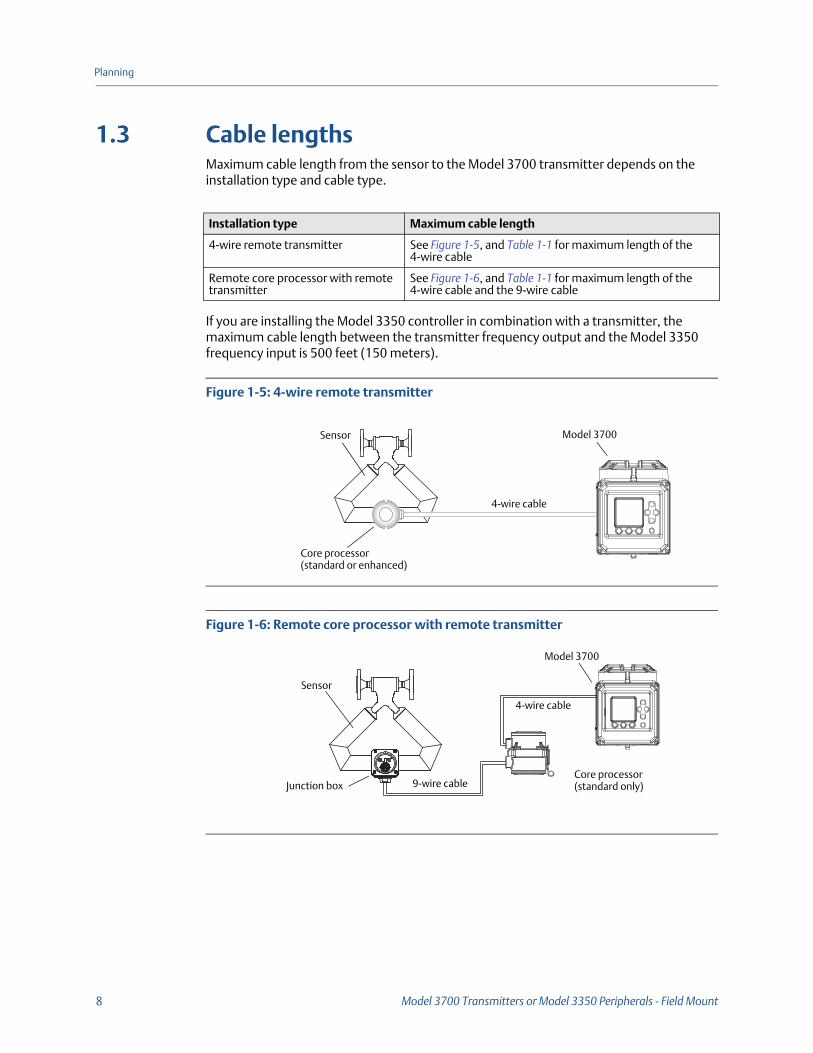
1.3 Cable lengthsMaximum cable length from the sensor to the Model 3700 transmitter depends on the installation type and cable type.
If you are installing the Model 3350 controller in combination with a transmitter, the maximum cable length between the transmitter frequency output and the Model 3350 frequency input is 500 feet (150 meters).
Figure 1-5: 4-wire remote transmitter
Figure 1-6: Remote core processor with remote transmitter
Installation type Maximum cable length
4-wire remote transmitter See Figure 1-5, and Table 1-1 for maximum length of the 4-wire cable
Remote core processor with remote transmitter
See Figure 1-6, and Table 1-1 for maximum length of the 4-wire cable and the 9-wire cable
Model 3700
4-wire cable
Sensor
Core processor(standard or enhanced)
Sensor
Junction box 9-wire cable
4-wire cable
Model 3700
Core processor(standard only)
Installation Manual 9
Planning
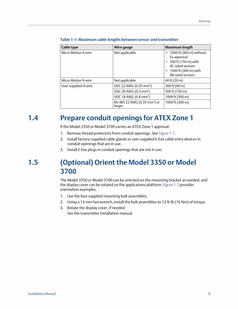
1.4 Prepare conduit openings for ATEX Zone 1If the Model 3350 or Model 3700 carries an ATEX Zone 1 approval:
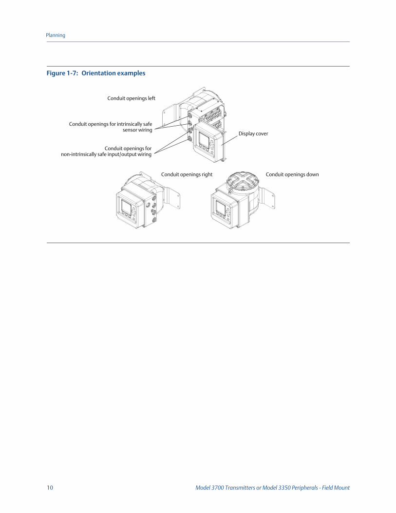
1. Remove thread protectors from conduit openings. See Figure 1-7.
2. Install factory-supplied cable glands or user-supplied E-Exe cable entry devices in conduit openings that are in use.
3. Install E-Exe plugs in conduit openings that are not in use.
1.5 (Optional) Orient the Model 3350 or Model 3700The Model 3350 or Model 3700 can be oriented on the mounting bracket as needed, and the display cover can be rotated on the applications platform. Figure 1-7 provides orientation examples.
1. Use the four supplied mounting bolt assemblies.
2. Using a 13 mm hex wrench, install the bolt assemblies to 12 ft-lb (16 Nm) of torque.
3. Rotate the display cover, if needed.See the transmitter installation manual.
Table 1-1: Maximum cable lengths between sensor and transmitter
Cable type Wire gauge Maximum length
Micro Motion 4-wire Not applicable • 1000 ft (300 m) without Ex-approval
• 500 ft (150 m) with IIC-rated sensors
• 1000 ft (300 m) with IIB-rated sensors
Micro Motion 9-wire Not applicable 60 ft (20 m)
User-supplied 4-wire VDC 22 AWG (0.35 mm2) 300 ft (90 m)
VDC 20 AWG (0.5 mm2) 500 ft (150 m)
VDC 18 AWG (0.8 mm2) 1000 ft (300 m)
RS-485 22 AWG (0.35 mm2) or larger
1000 ft (300 m)
10 Model 3700 Transmitters or Model 3350 Peripherals - Field Mount
Planning
Figure 1-7: Orientation examples
Conduit openings fornon-intrinsically safe input/output wiring
Conduit openings for intrinsically safesensor wiring
Display cover
Conduit openings right Conduit openings down
Conduit openings left
Installation Manual 11
Mounting
2 Mounting
2.1 Mount the applications platform• For flat-surface mounting, see Section 2.1.1.
• For pole mounting, see Section 2.1.2.
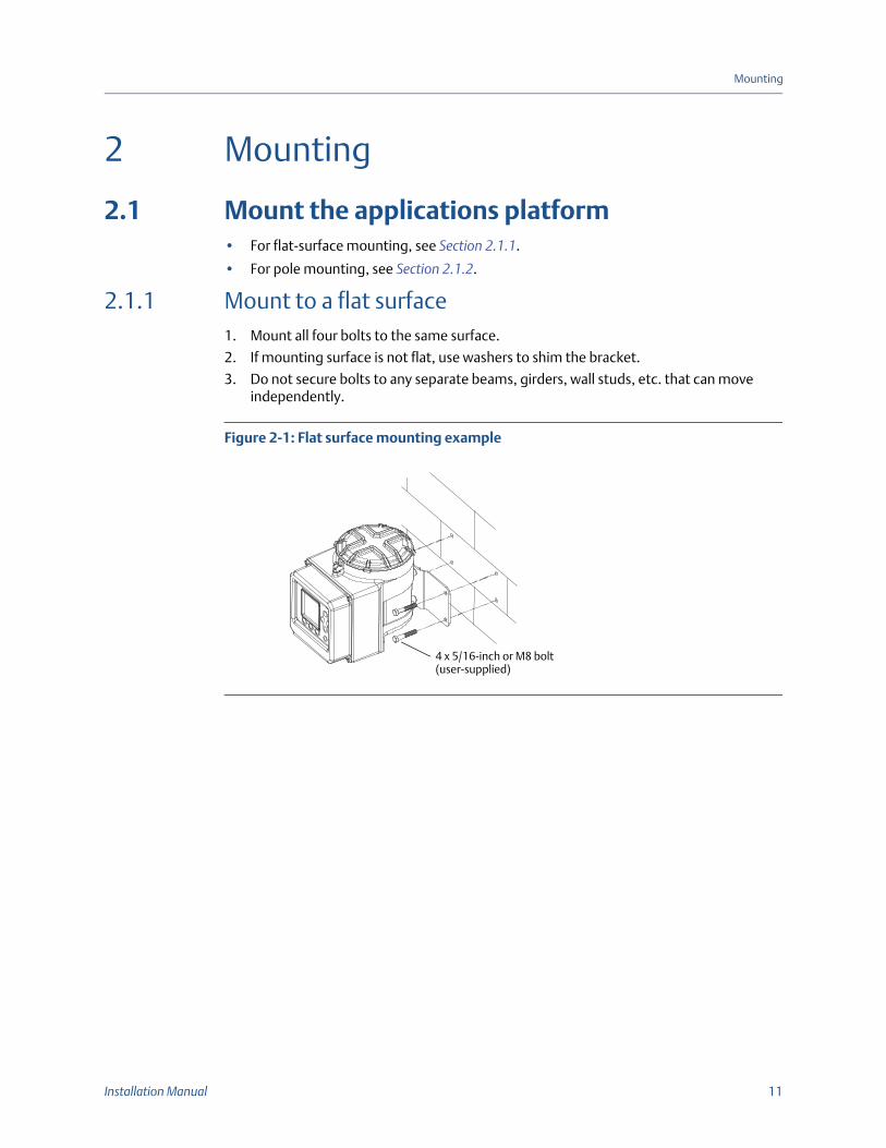
2.1.1 Mount to a flat surface1. Mount all four bolts to the same surface.
2. If mounting surface is not flat, use washers to shim the bracket.
3. Do not secure bolts to any separate beams, girders, wall studs, etc. that can move independently.
Figure 2-1: Flat surface mounting example
4 x 5/16-inch or M8 bolt(user-supplied)
12 Model 3700 Transmitters or Model 3350 Peripherals - Field Mount
Mounting
2.1.2 Mount to a pole
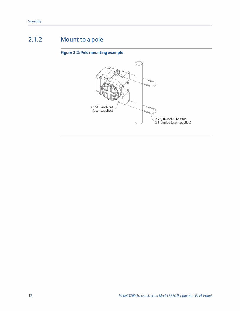
Figure 2-2: Pole mounting example
4 x 5/16 inch nut(user-supplied)
2 x 5/16-inch U bolt for 2-inch pipe (user-supplied)
Installation Manual 13
Mounting
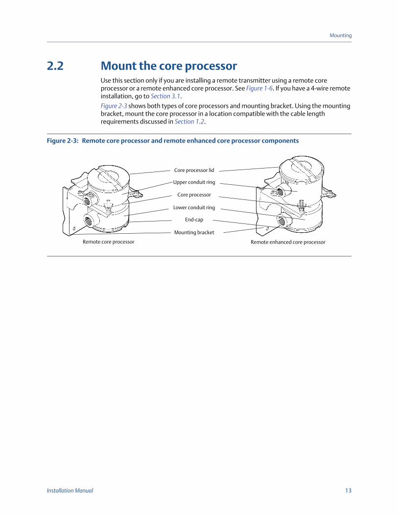
2.2 Mount the core processorUse this section only if you are installing a remote transmitter using a remote core processor or a remote enhanced core processor. See Figure 1-6. If you have a 4-wire remote installation, go to Section 3.1.
Figure 2-3 shows both types of core processors and mounting bracket. Using the mounting bracket, mount the core processor in a location compatible with the cable length requirements discussed in Section 1.2.
Figure 2-3: Remote core processor and remote enhanced core processor components
Core processor lid
Upper conduit ring
Core processor
Lower conduit ring
End-cap
Mounting bracket
Remote core processor Remote enhanced core processor

14 Model 3700 Transmitters or Model 3350 Peripherals - Field Mount
Mounting
Installation Manual 15
Wiring
3 Wiring
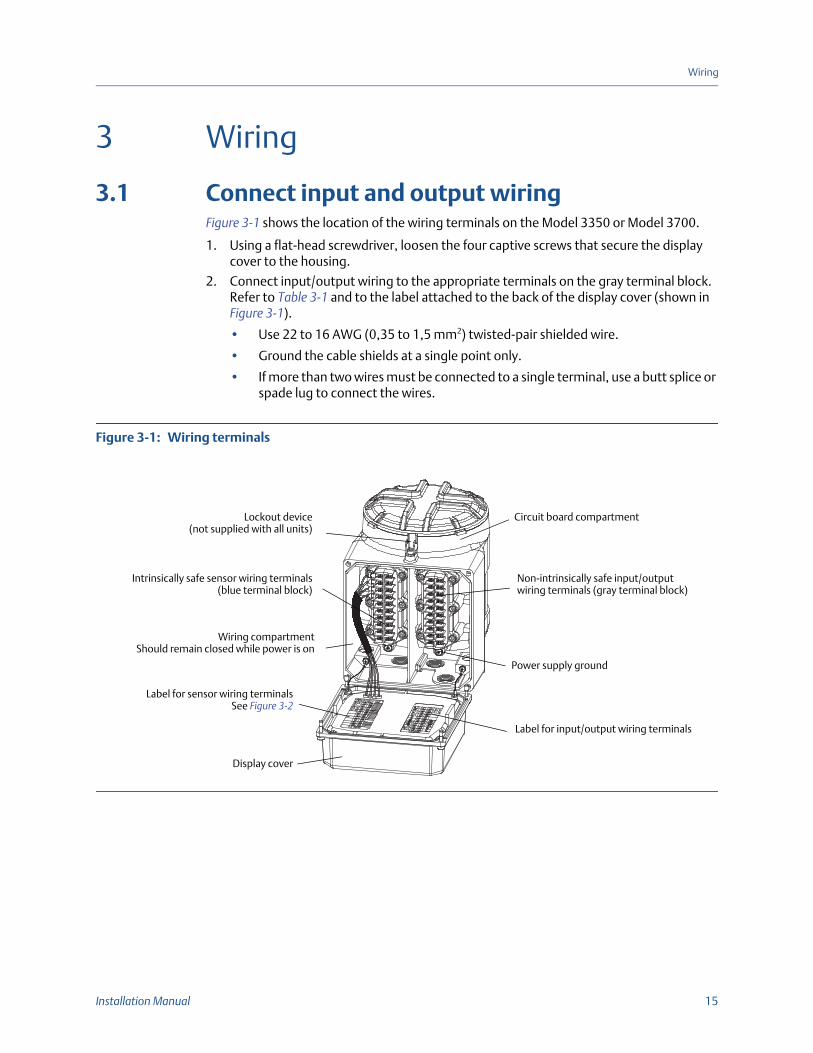
3.1 Connect input and output wiringFigure 3-1 shows the location of the wiring terminals on the Model 3350 or Model 3700.
1. Using a flat-head screwdriver, loosen the four captive screws that secure the display cover to the housing.
2. Connect input/output wiring to the appropriate terminals on the gray terminal block. Refer to Table 3-1 and to the label attached to the back of the display cover (shown in Figure 3-1).
• Use 22 to 16 AWG (0,35 to 1,5 mm2) twisted-pair shielded wire.
• Ground the cable shields at a single point only.
• If more than two wires must be connected to a single terminal, use a butt splice or spade lug to connect the wires.
Figure 3-1: Wiring terminals
Intrinsically safe sensor wiring terminals(blue terminal block)
Circuit board compartment
Wiring compartmentShould remain closed while power is on
Label for sensor wiring terminalsSee Figure 3-2
Lockout device(not supplied with all units)
Non-intrinsically safe input/output wiring terminals (gray terminal block)
Power supply ground
Label for input/output wiring terminals
Display cover
16 Model 3700 Transmitters or Model 3350 Peripherals - Field Mount
Wiring
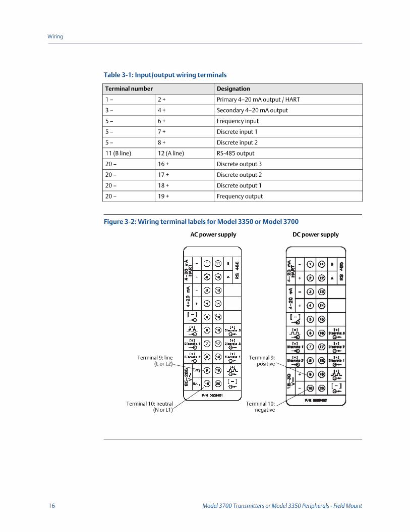
Figure 3-2: Wiring terminal labels for Model 3350 or Model 3700
Table 3-1: Input/output wiring terminals
Terminal number Designation
1 – 2 + Primary 4–20 mA output / HART
3 – 4 + Secondary 4–20 mA output
5 – 6 + Frequency input
5 – 7 + Discrete input 1
5 – 8 + Discrete input 2
11 (B line) 12 (A line) RS-485 output
20 – 16 + Discrete output 3
20 – 17 + Discrete output 2
20 – 18 + Discrete output 1
20 – 19 + Frequency output
AC power supply
Terminal 9:positive
Terminal 10:negative
Terminal 9: line(L or L2)
Terminal 10: neutral(N or L1)
DC power supply
Installation Manual 17
Wiring
3.2 Connect the Model 3700 to the sensor• If you are installing the Model 3350 controller, this step is not required. Go to Section
3.4.
• To connect the Model 3700 transmitter to a Micro Motion sensor, follow the instructions in this section.
3.2.1 Installation optionsThe Model 3700 can be wired to the sensor in either of the following configurations:
• 4-wire remote transmitter (requires a 4-wire cable). See Figure 1-5 and Section 3.2.2.
• Remote core processor with remote transmitter (requires both a 4-wire and a 9-wire cable). See Figure 1-6 and Section 3.2.3.
3.2.2 Wiring instructions for 4-wire remote installations1. Prepare the cable as described in the sensor documentation.
2. Connect the cable to the core processor as described in the sensor documentation.
3. To connect the cable to the transmitter:
a. Identify the wires in the 4-wire cable.
Use the 4-wire cable supplied by Micro Motion. This cable consists of one pair of 18 AWG (0,75 mm2) wires (red and black) for the VDC connection, and one pair of 22 AWG (0,35 mm2) wire (green and white) for the RS-485 connection.
b. Connect the four wires from the core processor to the appropriate terminals on the transmitter.
See Table 3-2 and Figure 3-3 (standard core processor) or Figure 3-3 (enhanced core processor).
• Do not leave bare wires exposed.
• Do not ground the shield or drain wires at the transmitter.
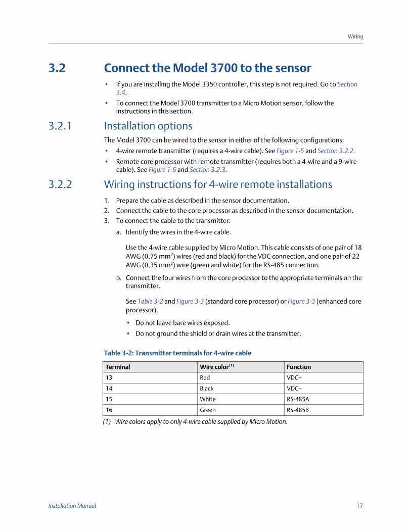
Table 3-2: Transmitter terminals for 4-wire cable
Terminal Wire color(1)
(1) Wire colors apply to only 4-wire cable supplied by Micro Motion.
Function
13 Red VDC+
14 Black VDC–
15 White RS-485A
16 Green RS-485B
18 Model 3700 Transmitters or Model 3350 Peripherals - Field Mount
Wiring
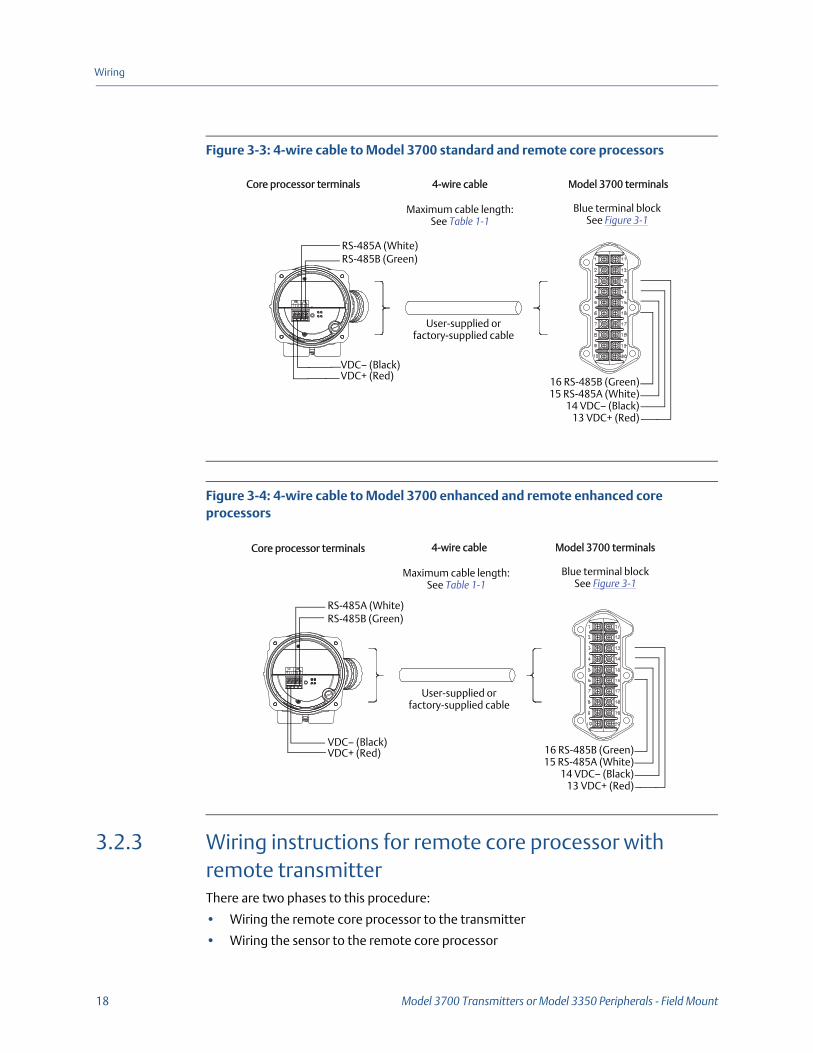
Figure 3-3: 4-wire cable to Model 3700 standard and remote core processors
Figure 3-4: 4-wire cable to Model 3700 enhanced and remote enhanced core processors
3.2.3 Wiring instructions for remote core processor with remote transmitterThere are two phases to this procedure:
• Wiring the remote core processor to the transmitter
• Wiring the sensor to the remote core processor
Core processor terminals 4-wire cable Model 3700 terminals
Blue terminal block See Figure 3-1
Maximum cable length:See Table 1-1
User-supplied or factory-supplied cable
16 RS-485B (Green)15 RS-485A (White)
14 VDC– (Black)13 VDC+ (Red)
RS-485B (Green)RS-485A (White)
VDC+ (Red)VDC– (Black)
Core processor terminals 4-wire cable Model 3700 terminals
Blue terminal block See Figure 3-1
VDC+ (Red)
RS-485B (Green)RS-485A (White)
Maximum cable length:See Table 1-1
User-supplied or factory-supplied cable
16 RS-485B (Green)15 RS-485A (White)
14 VDC– (Black)13 VDC+ (Red)
VDC– (Black)
Installation Manual 19
Wiring
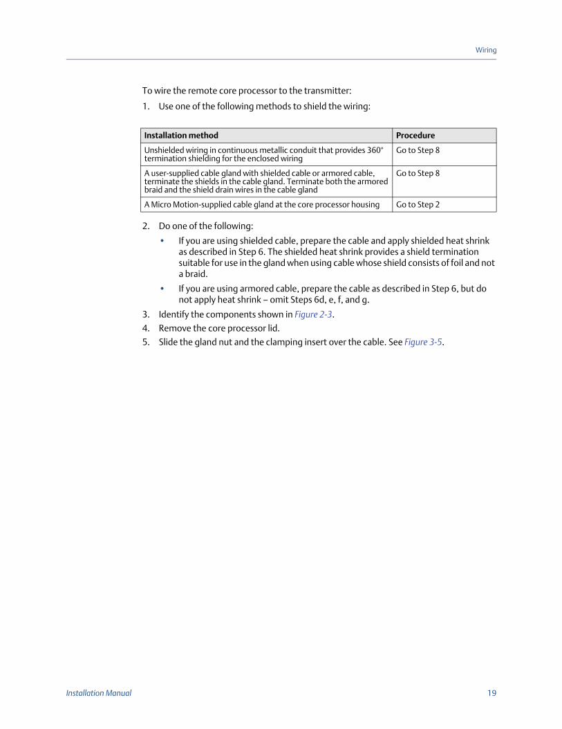
To wire the remote core processor to the transmitter:
1. Use one of the following methods to shield the wiring:
2. Do one of the following:
• If you are using shielded cable, prepare the cable and apply shielded heat shrink as described in Step 6. The shielded heat shrink provides a shield termination suitable for use in the gland when using cable whose shield consists of foil and not a braid.
• If you are using armored cable, prepare the cable as described in Step 6, but do not apply heat shrink – omit Steps 6d, e, f, and g.
3. Identify the components shown in Figure 2-3.
4. Remove the core processor lid.
5. Slide the gland nut and the clamping insert over the cable. See Figure 3-5.
Installation method Procedure
Unshielded wiring in continuous metallic conduit that provides 360° termination shielding for the enclosed wiring
Go to Step 8
A user-supplied cable gland with shielded cable or armored cable, terminate the shields in the cable gland. Terminate both the armored braid and the shield drain wires in the cable gland
Go to Step 8
A Micro Motion-supplied cable gland at the core processor housing Go to Step 2
20 Model 3700 Transmitters or Model 3350 Peripherals - Field Mount
Wiring
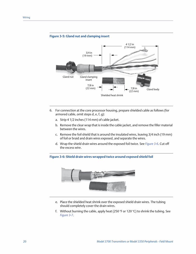
Figure 3-5: Gland nut and clamping insert
6. For connection at the core processor housing, prepare shielded cable as follows (for armored cable, omit steps d, e, f, g):
a. Strip 4 1/2 inches (114 mm) of cable jacket.
b. Remove the clear wrap that is inside the cable jacket, and remove the filler material between the wires.
c. Remove the foil shield that is around the insulated wires, leaving 3/4 inch (19 mm) of foil or braid and drain wires exposed, and separate the wires.
d. Wrap the shield drain wires around the exposed foil twice. See Figure 3-6. Cut off the excess wire.
Figure 3-6: Shield drain wires wrapped twice around exposed shield foil
e. Place the shielded heat shrink over the exposed shield drain wires. The tubing should completely cover the drain wires.
f. Without burning the cable, apply heat (250 °F or 120 °C) to shrink the tubing. See Figure 3-7.
Shielded heat shrink
Gland body
4 1/2 in(114 mm)
3/4 in(19 mm)
7/8 in (22 mm) 7/8 in
(22 mm)
Gland nut Gland clamping insert
Installation Manual 21
Wiring
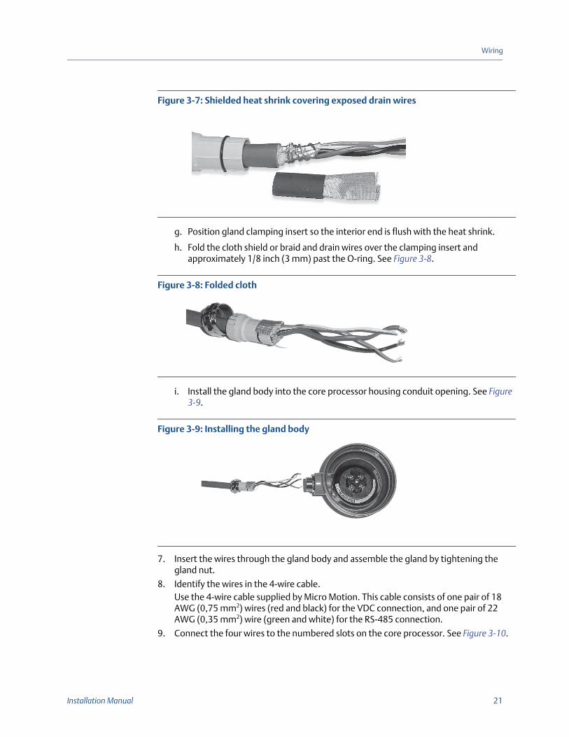
Figure 3-7: Shielded heat shrink covering exposed drain wires
g. Position gland clamping insert so the interior end is flush with the heat shrink.
h. Fold the cloth shield or braid and drain wires over the clamping insert and approximately 1/8 inch (3 mm) past the O-ring. See Figure 3-8.
Figure 3-8: Folded cloth
i. Install the gland body into the core processor housing conduit opening. See Figure 3-9.
Figure 3-9: Installing the gland body
7. Insert the wires through the gland body and assemble the gland by tightening the gland nut.
8. Identify the wires in the 4-wire cable. Use the 4-wire cable supplied by Micro Motion. This cable consists of one pair of 18 AWG (0,75 mm2) wires (red and black) for the VDC connection, and one pair of 22 AWG (0,35 mm2) wire (green and white) for the RS-485 connection.
9. Connect the four wires to the numbered slots on the core processor. See Figure 3-10.

22 Model 3700 Transmitters or Model 3350 Peripherals - Field Mount
Wiring
Figure 3-10: Connect the four wires to the numbered slots
10. Connect the core processor housing internal ground screw if earth ground is required.Earth ground is required if the core processor cannot be grounded via sensor piping, and local codes require internal ground connections.
Do not connect shield drain wires to this terminal.
11. Reinstall and tighten the core processor lid.
12. To connect the cable to the transmitter, connect the four wires from the core processor to the appropriate terminals on the transmitter. See Table 3-2 and Figure 3-3.
• Do not leave bare wires exposed.
• Do not ground the shield or drain wires at the transmitter.
3.3 Wire the sensor to the remote core processor
WARNING!Do not twist the core processor, as this will damage the sensor.
CAUTION!Do not allow the shield drain wires to contact the sensor junction box, as this can cause meter errors.
Power supply +(Red wire)
Power supply –(Black wire)
RS-485A (White wire)
RS-485B(Green wire)
Core processor housing internal ground screw
Installation Manual 23
Wiring
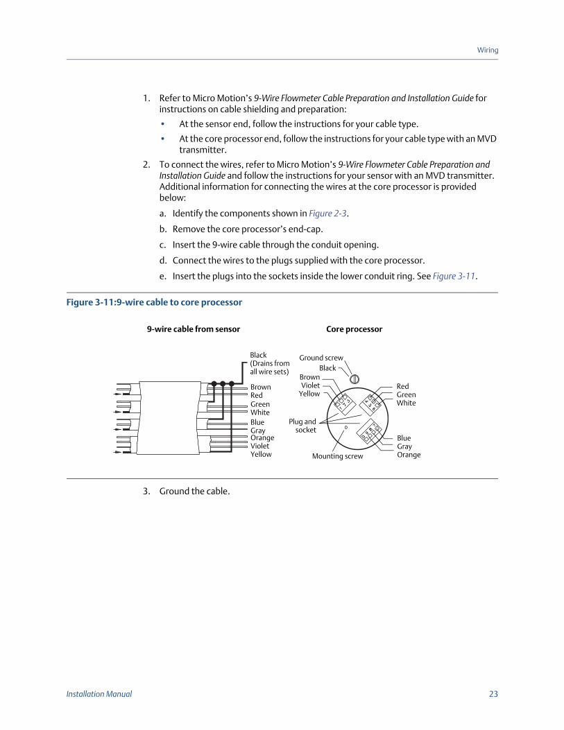
1. Refer to Micro Motion’s 9-Wire Flowmeter Cable Preparation and Installation Guide for instructions on cable shielding and preparation:
• At the sensor end, follow the instructions for your cable type.
• At the core processor end, follow the instructions for your cable type with an MVD transmitter.
2. To connect the wires, refer to Micro Motion’s 9-Wire Flowmeter Cable Preparation and Installation Guide and follow the instructions for your sensor with an MVD transmitter. Additional information for connecting the wires at the core processor is provided below:
a. Identify the components shown in Figure 2-3.
b. Remove the core processor’s end-cap.
c. Insert the 9-wire cable through the conduit opening.
d. Connect the wires to the plugs supplied with the core processor.
e. Insert the plugs into the sockets inside the lower conduit ring. See Figure 3-11.
Figure 3-11:9-wire cable to core processor
3. Ground the cable.
BrownRedGreenWhiteBlueGrayOrangeVioletYellow
Black(Drains from all wire sets)
Plug andsocket
Mounting screw
BlueGrayOrange
RedGreenWhite
BrownViolet
Yellow
Ground screwBlack
9-wire cable from sensor Core processor
24 Model 3700 Transmitters or Model 3350 Peripherals - Field Mount
Wiring
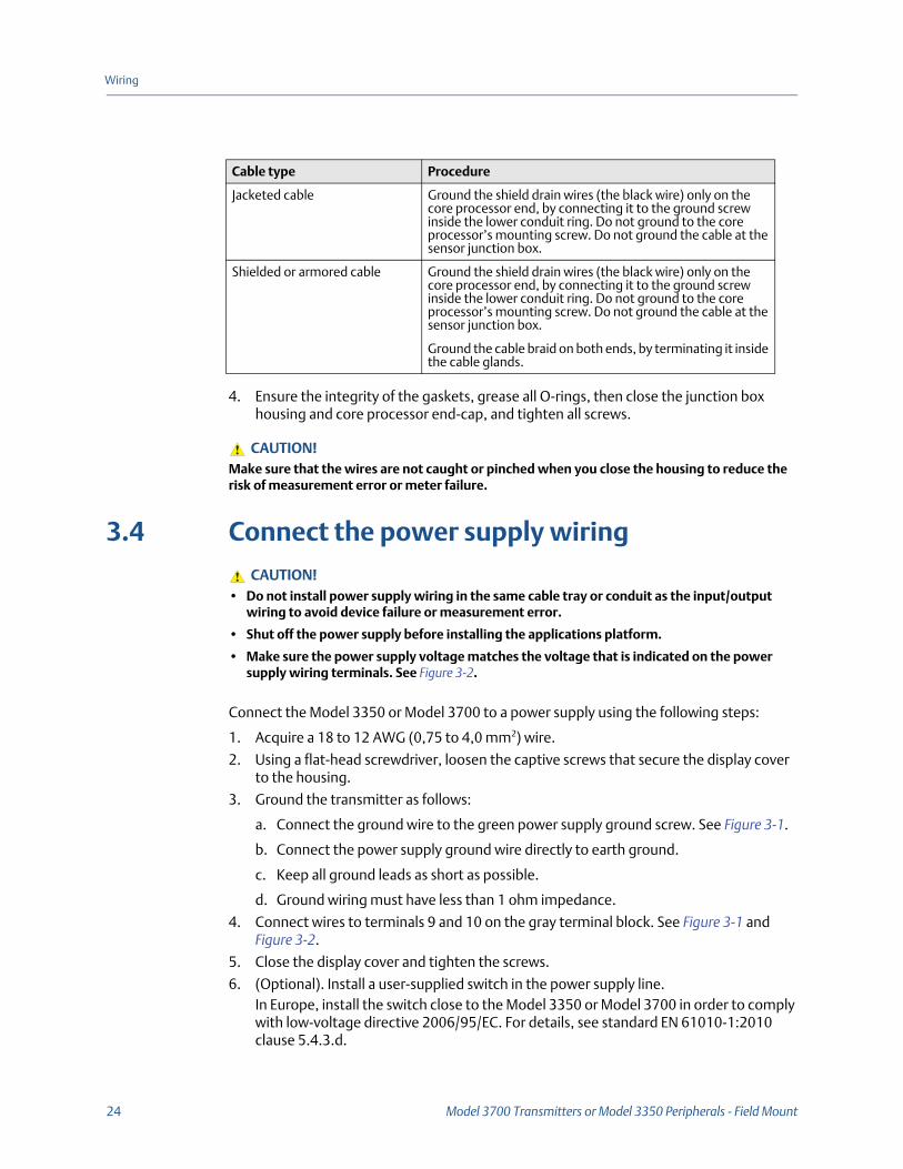
4. Ensure the integrity of the gaskets, grease all O-rings, then close the junction box housing and core processor end-cap, and tighten all screws.
3.4 Connect the power supply wiring
Connect the Model 3350 or Model 3700 to a power supply using the following steps:
1. Acquire a 18 to 12 AWG (0,75 to 4,0 mm2) wire.
2. Using a flat-head screwdriver, loosen the captive screws that secure the display cover to the housing.
3. Ground the transmitter as follows:
a. Connect the ground wire to the green power supply ground screw. See Figure 3-1.
b. Connect the power supply ground wire directly to earth ground.
c. Keep all ground leads as short as possible.
d. Ground wiring must have less than 1 ohm impedance.
4. Connect wires to terminals 9 and 10 on the gray terminal block. See Figure 3-1 and Figure 3-2.
5. Close the display cover and tighten the screws.
6. (Optional). Install a user-supplied switch in the power supply line. In Europe, install the switch close to the Model 3350 or Model 3700 in order to comply with low-voltage directive 2006/95/EC. For details, see standard EN 61010-1:2010 clause 5.4.3.d.
Cable type Procedure
Jacketed cable Ground the shield drain wires (the black wire) only on the core processor end, by connecting it to the ground screw inside the lower conduit ring. Do not ground to the core processor’s mounting screw. Do not ground the cable at the sensor junction box.
Shielded or armored cable Ground the shield drain wires (the black wire) only on the core processor end, by connecting it to the ground screw inside the lower conduit ring. Do not ground to the core processor’s mounting screw. Do not ground the cable at the sensor junction box.
Ground the cable braid on both ends, by terminating it inside the cable glands.
CAUTION!Make sure that the wires are not caught or pinched when you close the housing to reduce the risk of measurement error or meter failure.
CAUTION!• Do not install power supply wiring in the same cable tray or conduit as the input/output
wiring to avoid device failure or measurement error.
• Shut off the power supply before installing the applications platform.
• Make sure the power supply voltage matches the voltage that is indicated on the power supply wiring terminals. See Figure 3-2.

*20001008*20001008
Rev BA2015
Micro Motion Inc. USAWorldwide Headquarters7070 Winchester CircleBoulder, Colorado 80301T +1 303-527-5200T +1 800-522-6277F +1 303-530-8459www.micromotion.com
Micro Motion EuropeEmerson Process ManagementNeonstraat 16718 WX EdeThe NetherlandsT +31 (0) 318 495 555F +31 (0) 318 495 556www.micromotion.nl
Micro Motion JapanEmerson Process Management1-2-5, Higashi ShinagawaShinagawa-kuTokyo 140-0002 JapanT +81 3 5769-6803F +81 3 5769-6844
Micro Motion AsiaEmerson Process Management1 Pandan CrescentSingapore 128461Republic of SingaporeT +65 6777-8211F +65 6770-8003
Micro Motion United KingdomEmerson Process Management LimitedHorsfield WayBredbury Industrial EstateStockport SK6 2SU U.K.T +44 0870 240 1978F +44 0800 966 181
©2015 Micro Motion, Inc. All rights reserved.
The Emerson logo is a trademark and service mark of Emerson Electric Co. Micro Motion, ELITE, ProLink, MVD and MVD Direct Connect marks are marks of one of the Emerson Process Management family of companies. All other marks are property of their respective owners.