Embed Size (px)
Citation preview
A micro-mechanical model for the homogenisation of masonry
A. Zucchini a,1, P.B. Lourenc�o b,*
a ENEA, FIS. MET, C.R.E. E.Clementel, v.Don Fiammell, 2, I-40129 Bologna, Italyb Department of Civil Engineering, University of Minho, Azur�eem, P-4800-058 Guimar~aaes, Portugal
Received 12 April 2000; received in revised form 17 February 2002
Abstract
Masonry is a composite material made of units (brick, blocks, etc.) and mortar. For periodic arrangements of the
units, the homogenisation techniques represent a powerful tool for structural analysis. The main problem pending is the
errors introduced in the homogenisation process when large difference in stiffness are expected for the two components.
This issue is obvious in the case of non-linear analysis, where the tangent stiffness of one component or the tangent
stiffness of the two components tends to zero with increasing inelastic behaviour.
The paper itself does not concentrate on the issue of non-linear homogenisation. But as the accuracy of the model is
assessed for an increasing ratio between the stiffness of the two components, the benefits of adopting the proposed
method for non-linear analysis are demonstrated. Therefore, the proposed model represents a major step in the ap-
plication of homogenisation techniques for masonry structures.
The micro-mechanical model presented has been derived from the actual deformations of the basic cell and includes
additional internal deformation modes, with regard to the standard two-step homogenisation procedure. These
mechanisms, which result from the staggered alignment of the units in the composite, are of capital importance for the
global response. For the proposed model, it is shown that, up to a stiffness ratio of one thousand, the maximum error in
the calculation of the homogenised Young’s moduli is lower than five percent. It is also shown that the anisotropic
failure surface obtained from the homogenised model seems to represent well experimental results available in the
literature. � 2002 Elsevier Science Ltd. All rights reserved.
Keywords: Composites; Numerical techniques; Homogenisation techniques; Masonry
1. Introduction
Masonry is a composite material made of units and mortar, normally arranged periodically. Utilising thematerial parameters obtained from experiments and the actual geometry of both components, viz. units(e.g. bricks, blocks or stones) and joints, it is possible to numerically reproduce the behaviour of masonrystructures, see e.g. Lofti and Shing (1994), and Lourenc�o and Rots (1997). Nevertheless, the representationof each unit and each joint becomes impractical in case of real masonry structures comprising a largenumber of units.
International Journal of Solids and Structures 39 (2002) 3233–3255
www.elsevier.com/locate/ijsolstr
* Corresponding author. Tel.: +351-253-510200; fax: +351-253-510217.
E-mail addresses: [email protected] (A. Zucchini), [email protected] (P.B. Lourenc�o).1 Tel.: +39-0516098256; fax: +39-0516098062.
0020-7683/02/$ - see front matter � 2002 Elsevier Science Ltd. All rights reserved.
PII: S0020-7683 (02 )00230-5

The alternative is to describe the composite behaviour of masonry in terms of macro or average stressesand strains so that the material can be assumed homogeneous. This problem can be approached, basically,from two directions. A possible direction is to gather extensive experimental data that can be used confi-dently in the analyses. It is stressed that the results are limited to the conditions under which the data areobtained. New materials and/or application of a well known material in different loading conditions mightrequire a different set of costly experimental programs. Another direction, adopted in this paper, is to seek amore fundamental approach which resorts to homogenisation techniques. This approach, which aims atdescribing the behaviour of the composite from the geometry and behaviour of the representative volumeelement (or basic cell, see Fig. 1), grants us a predictive capability.
The techniques of homogenisation (Bakhvalov and Panasenko, 1989) are currently becoming increas-ingly popular among the masonry community. A method that would permit to establish constitutive re-lations in terms of averaged stresses and strains from the geometry and constitutive relations of theindividual components would represent a major step forward in masonry modelling. Given the difficultgeometry of the masonry basic cell, a close-form solution of the homogenisation problem seems to beimpossible, which leads, basically, to three different lines of action.
The first, very powerful approach is to handle the brickwork structure of masonry by considering thesalient features of the discontinuum within the framework of a generalised/Cosserat continuum theory.This elegant and efficient solution (Besdo, 1985; M€uuhlhaus, 1993) possesses some inherent mathematicalcomplexity and has not been adopted by many researchers, even though being capable of handling the unit–mortar interface and true discontinuum behaviour. The step towards the practical application of such anapproach is still to be done.
A second approach (Anthoine, 1995, 1997; Urbanski et al., 1995) is to apply rigorously the homoge-nisation theory for periodic media to the basic cell, i.e. to carry out a single step homogenisation, withadequate boundary conditions and exact geometry. It is stressed that the unit–mortar interface has not yetbeen accounted for by researchers. The complexity of the masonry basic cell implies a numerical solution ofthe problem, which has been obtained using the finite element method. The theory was thus used by thecited authors to determine macro-parameters of masonry and not, actually, to carry out analysis at thestructural level. In fact, the rigorous application of the homogenisation theory for the non-linear behaviourof the complex masonry basic cell implies solving the problem for all possible macroscopic loading his-tories, since the superposition principle does not apply anymore. Thus, the complete determination of thehomogenised constitutive law would require an infinite number of computations.
The third approach can be considered as an ‘‘engineering approach’’, 2 aiming at substituting thecomplex geometry of the basic cell by a simplified geometry so that a close-form solution of the homog-
Fig. 1. Basic cell for masonry and objective of homogenisation.
2 ‘‘Engineering’’ is used here not in the sense that it is empiric or practical but in the sense that must be engineered from reasoning.
3234 A. Zucchini, P.B. Lourenc�o / International Journal of Solids and Structures 39 (2002) 3233–3255
enisation problem is possible. Keeping in mind the objective of performing analysis at the structural level,Pande et al. (1989), Maier et al. (1991) and Pietruszczak and Niu (1992) introduced homogenisationtechniques in an approximate manner. The homogenisation has generally been performed in two steps,head (or vertical) and bed (or horizontal) joints being introduced successively. In this case masonry can beassumed to be a layered material, which simplifies the problem significantly. Lourenc�o (1996) further de-veloped the procedure, presenting a novel matrix formulation that allows a much clearer implementation oflinear elastic homogenisation algorithms and also a relatively simple extension to non-linear behaviour.Again, it is stressed that the unit–mortar interface has not been accounted for by the cited researchers.
The use of two separate homogenisation steps does not explicitly account for the regular offset of verticalmortar joints belonging to two consecutive layered unit courses. Moreover, the final result depends on theorder in which the two homogenisation processes are carried out. Nevertheless, this simplified homoge-nisation approach has been used by several authors and performs very satisfactorily in the case of linearelastic analysis (Anthoine, 1995; Lourenc�o, 1997). For the case of non-linear analysis, where the ratiobetween the stiffness of unit and mortar becomes larger, the simplified homogenisation approach leads tonon-acceptable errors and should not be used. Lourenc�o (1997) has shown that large errors can occur in thestandard two-step homogenisation technique if there are large differences of stiffness (>10) between unitand mortar. Anthoine (1995, 1997) has shown that the standard two-step homogenisation technique doesnot take into account the arrangement of the units in the sense that different bond patterns (running bondand stack bond for example) may lead to exactly the same result.
A different engineering approach has been proposed by Bati et al. (1999), in which a close-form solution ofthe periodic arrangement of units and mortar has been obtained, by substituting the parallelepiped-shapedunits by elliptic cylinders. This mathematically elegant solution does not represent well the geometry and it isunclear if it represents an advantage with regard to the standard two-step homogenisation technique.
The present paper presents a new micro-mechanical model, for masonry in stretcher bond, 3 to overcomethe limitations of the standard two-step homogenisation by a more detailed simulation of the interactionsbetween the different internal components of the basic cell. The model can still be considered as an engi-neering approach, in which an ingenious observation of the behaviour of masonry leads to the simulation ofadditional internal deformation mechanisms of the joints, that become more and more important for in-creasing unit/mortar stiffness ratios. At this stage, the unit–mortar interface is not considered in the model.
It is noted that micro-mechanical approaches that consider additional internal deformation mechanismshave been derived independently by van der Pluijm (1999) for the analysis of masonry subjected to flexuralbending and by Lopez et al. (1999) for the non-linear analysis of masonry walls subjected to in-plane loading.
In this paper, the full three-dimensional behaviour will be considered and attention will be given to acomparison between the results from a detailed finite element analysis (FEA) and the proposed micro-mechanical homogenisation model, in order to demonstrate the efficiency of the proposed solution. Finally,the adequacy of the model to reproduce the anisotropic failure surface of masonry will be discussed bymeans of a comparison with available experimental results.
2. Descriptive analysis of masonry
As a consequence of the differences in stiffness between units and mortar, a complex interaction betweenthe two masonry components occurs when masonry is deformed. The differences in stiffness cause a unequaldistribution of deformations over units and mortar, compared with the average deformation of masonry
3 ‘‘Stretcher bond’’ represents the typical arrangement of masonry units in a wall, with an offset half unit for the vertical mortar
joints belonging to two consecutive masonry courses. The ‘‘stacked bond’’ arrangement, in which the vertical joints run continuously
through all the courses, is not allowed for structural purposes by most masonry codes.
A. Zucchini, P.B. Lourenc�o / International Journal of Solids and Structures 39 (2002) 3233–3255 3235
composite. As a result the individual (internal) stresses of units and mortar deviate from the average(external) stresses of the composite.
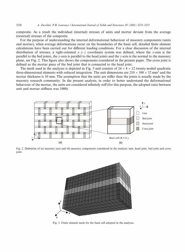
For the purpose of understanding the internal deformational behaviour of masonry components (unitsand mortar), when average deformations occur on the boundaries of the basic cell, detailed finite elementcalculations have been carried out for different loading conditions. For a clear discussion of the internaldistribution of stresses, a right-oriented x–y–z coordinate system was defined, where the x-axis is theparallel to the bed joints, the y-axis is parallel to the head joints and the z-axis is the normal to the masonryplane, see Fig. 2. This figure also shows the components considered in the present paper. The cross joint isdefined as the mortar piece of the bed joint that is connected to the head joint.
The mesh used in the analyses is depicted in Fig. 3 and consists of 24� 4� 12 twenty-noded quadraticthree-dimensional elements with reduced integration. The unit dimensions are 210� 100� 52 mm3 and themortar thickness is 10 mm. The assumption that the units are stiffer than the joints is usually made by themasonry research community. In the present analysis, in order to better understand the deformationalbehaviour of the mortar, the units are considered infinitely stiff (for this purpose, the adopted ratio betweenunit and mortar stiffness was 1000).
Fig. 2. Definition of (a) masonry axes and (b) masonry components considered in the analysis: unit, head joint, bed joint and cross
joint.
Fig. 3. Finite element mesh for the basic cell adopted in the analyses.
3236 A. Zucchini, P.B. Lourenc�o / International Journal of Solids and Structures 39 (2002) 3233–3255
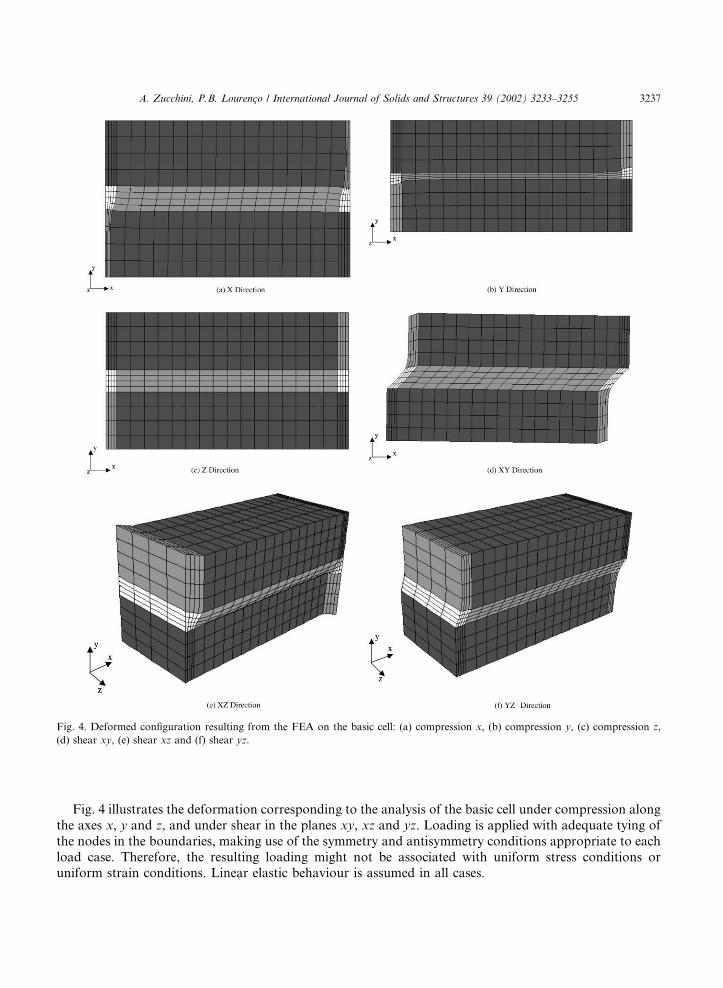
Fig. 4 illustrates the deformation corresponding to the analysis of the basic cell under compression alongthe axes x, y and z, and under shear in the planes xy, xz and yz. Loading is applied with adequate tying ofthe nodes in the boundaries, making use of the symmetry and antisymmetry conditions appropriate to eachload case. Therefore, the resulting loading might not be associated with uniform stress conditions oruniform strain conditions. Linear elastic behaviour is assumed in all cases.
Fig. 4. Deformed configuration resulting from the FEA on the basic cell: (a) compression x, (b) compression y, (c) compression z,
(d) shear xy, (e) shear xz and (f) shear yz.
A. Zucchini, P.B. Lourenc�o / International Journal of Solids and Structures 39 (2002) 3233–3255 3237
Fig. 4a demonstrates that, for compression along the x-axis, the unit and the bed joint are mostlysubjected to normal stresses, the bed joint is strongly distorted in shear and the cross joint is subjected to amixed shear/normal stress action. While the cross joint effect can be neglected if the cross joint is smallcompared to the basic cell, the shear of the bed joint must be included in the micro-mechanical model ofmasonry for stiff units.
Fig. 4b demonstrates that, for compression along the y-axis, the unit and the bed joint are mostlysubjected to normal stresses, and the head and cross joints are subjected to a mixed shear/normal stressaction. These relatively local effects are difficult to include in the micro-mechanical model, have small in-fluence on the overall behaviour of the basic cell and will not be considered. This is confirmed by the resultsof Lourenc�o (1997) where it was shown that the standard two-step homogenisation technique, which ne-glects such effects, leads to almost exact results (errors smaller than 2% for ratios unit/mortar stiffness up to1000).
Fig. 4c demonstrates that, for compression along the z-axis, all components of the basic cell are subjectedto a truly homogeneous state of normal stress. This again is confirmed by the results of Lourenc�o (1997)where it was shown that the standard two-step homogenisation technique leads to almost exact results(errors smaller than 0.2% for ratios unit/mortar stiffness up to 1000).
Fig. 4d demonstrates that, for xy shear, the unit and the head joint are mostly subjected to shear stresses,the bed joint is strongly distorted in the normal direction (tension) and the cross joint is subjected to amixed shear/normal stress. Due to antisymmetric conditions, the neighbouring basic cells will featurenormal compression in the bed joint. While the cross joint effect can be neglected if the cross joint is smallcompared to the basic cell, the normal stress of the bed joint must be included in the micro-mechanicalmodel.
The deformation of the basic cell under xz shear is shown in Fig. 4e. The cell components are mostlysubjected to shear stresses, with unit and head joint deformed in the horizontal plane, while the bed joint isdistorted also in the vertical plane. Therefore the shear stress ryz cannot be neglected in a micro-mechanicalmodel.
Finally, the deformation of the basic cell under yz shear is shown in Fig. 4f. All cell components aremainly distorted by shear in the vertical plane, while minor local stress components do not produce sig-nificant overall effects.
3. Formulation of the micro-mechanical model
3.1. General
Lourenc�o (1997) has shown that large errors can occur in the standard two-step homogenisationtechnique if there are large differences of stiffness (>10) between unit and mortar. The micro-mechanicalmodel presented in this paper overcomes this limitation by a more detailed simulation of the interactionsbetween the different internal components of the basic cell.
The main idea of this approach, derived from observations of deformations calculated with the finiteelement analyses shown in the previous section, is that the standard two-step homogenisation techniqueneglects some deformation mechanisms of the bed joint, that become more and more important for in-creasing unit/mortar stiffness ratios, such as
• vertical normal stress in the bed joint, when the basic cell is loaded with in-plane shear;• in-plane shear of the bed joint, when the basic cell is loaded with an horizontal in-plane normal
stress;• out-of-plane shear ryz of the bed joint, when the basic cell is loaded with out-of-plane shear stress rxz.
3238 A. Zucchini, P.B. Lourenc�o / International Journal of Solids and Structures 39 (2002) 3233–3255
These mechanisms are due to the staggered alignment of the units in a masonry wall and are neglected bythe standard two-step homogenisation techniques, which are based on the assumption of continuousperpendicular head joints.
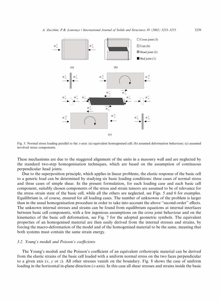
Due to the superposition principle, which applies in linear problems, the elastic response of the basic cellto a generic load can be determined by studying six basic loading conditions: three cases of normal stressand three cases of simple shear. In the present formulation, for each loading case and each basic cellcomponent, suitably chosen components of the stress and strain tensors are assumed to be of relevance forthe stress–strain state of the basic cell, while all the others are neglected, see Figs. 5 and 6 for examples.Equilibrium is, of course, ensured for all loading cases. The number of unknowns of the problem is largerthan in the usual homogenisation procedure in order to take into account the above ‘‘second-order’’ effects.The unknown internal stresses and strains can be found from equilibrium equations at internal interfacesbetween basic cell components, with a few ingenious assumptions on the cross joint behaviour and on thekinematics of the basic cell deformation, see Fig. 7 for the adopted geometric symbols. The equivalentproperties of an homogenised material are then easily derived from the internal stresses and strains, byforcing the macro-deformation of the model and of the homogenised material to be the same, meaning thatboth systems must contain the same strain energy.
3.2. Young’s moduli and Poisson’s coefficients
The Young’s moduli and the Poisson’s coefficient of an equivalent orthotropic material can be derivedfrom the elastic strains of the basic cell loaded with a uniform normal stress on the two faces perpendicularto a given axis (x, y or z). All other stresses vanish on the boundary. Fig. 8 shows the case of uniformloading in the horizontal in-plane direction (x-axis). In this case all shear stresses and strains inside the basic
Fig. 5. Normal stress loading parallel to the x-axis: (a) equivalent homogenised cell; (b) assumed deformation behaviour; (c) assumed
involved stress components.
A. Zucchini, P.B. Lourenc�o / International Journal of Solids and Structures 39 (2002) 3233–3255 3239
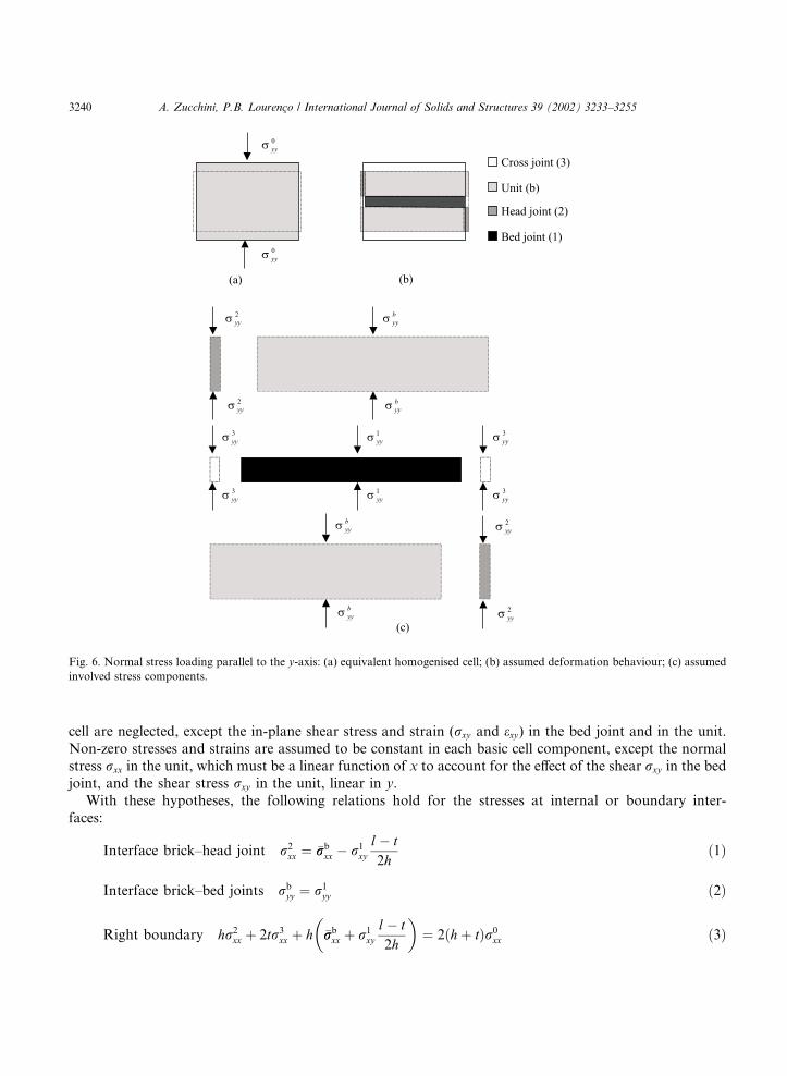
cell are neglected, except the in-plane shear stress and strain (rxy and exy) in the bed joint and in the unit.Non-zero stresses and strains are assumed to be constant in each basic cell component, except the normalstress rxx in the unit, which must be a linear function of x to account for the effect of the shear rxy in the bedjoint, and the shear stress rxy in the unit, linear in y.
With these hypotheses, the following relations hold for the stresses at internal or boundary inter-faces:
Interface brick–head joint r2xx ¼ �rrb
xx � r1xy
l� t2h
ð1Þ
Interface brick–bed joints rbyy ¼ r1
yy ð2Þ
Right boundary hr2xx þ 2tr3
xx þ h �rrbxx
�þ r1
xy
l� t2h
�¼ 2ðhþ tÞr0
xx ð3Þ
Fig. 6. Normal stress loading parallel to the y-axis: (a) equivalent homogenised cell; (b) assumed deformation behaviour; (c) assumed
involved stress components.
3240 A. Zucchini, P.B. Lourenc�o / International Journal of Solids and Structures 39 (2002) 3233–3255
Upper boundary lrbyy þ tr2
yy ¼ ðlþ tÞr0yy ð4Þ
Front boundary 2thr2zz þ 2ðl� tÞtr1
zz þ 2lhrbzz þ 4t2r3
zz ¼ ½2thþ 2ðlþ tÞt þ 2lh�r0zz ð5Þ
and for the strains:
Upper boundary 2te1yy þ hebyy ¼ he2yy þ 2te3yy ð6Þ
Right boundary te2xx þ l�eebxx ¼ 2te3xx þ ðl� tÞe1xx ð7Þ
Front boundary ebzz ¼ e1zz ð8Þ
Front boundary ebzz ¼ e2zz ð9Þ
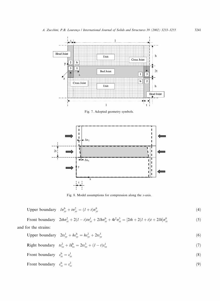
Fig. 7. Adopted geometry symbols.
Fig. 8. Model assumptions for compression along the x-axis.
A. Zucchini, P.B. Lourenc�o / International Journal of Solids and Structures 39 (2002) 3233–3255 3241
where l is half of the unit length, h is half of the unit height and t is half of the bed joint width. Unit, bedjoint, head joint and cross joint variables are indicated throughout this paper respectively by the super-scripts b, 1, 2 and 3, respectively. �rrb
xx and �eebxx are the mean value of the normal stress rxx and normal strain exxin the unit. r0
xx, r0yy , r0
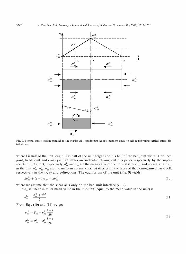
zz are the uniform normal (macro) stresses on the faces of the homogenised basic cell,respectively in the x-, y- and z-directions. The equilibrium of the unit (Fig. 9) yields:
hrb1xx þ ðl� tÞr1
xy ¼ hrb2xx ð10Þ
where we assume that the shear acts only on the bed–unit interface (l� t).If rb
xx is linear in x, its mean value in the mid-unit (equal to the mean value in the unit) is
�rrbxx ¼
rb1xx þ rb2
xx
2ð11Þ
From Eqs. (10) and (11) we get
rb1xx ¼ �rrb
xx � r1xy
l� t2h
rb2xx ¼ �rrb
xx þ r1xy
l� t2h
ð12Þ
Fig. 9. Normal stress loading parallel to the x-axis: unit equilibrium (couple moment equal to self-equilibrating vertical stress dis-
tribution).
3242 A. Zucchini, P.B. Lourenc�o / International Journal of Solids and Structures 39 (2002) 3233–3255
which have been used in Eqs. (1) and (3). The couple required for the momentum equilibrium of one-fourthof the unit in the basic cell (Fig. 5) derives from the neighbouring cell along y-axis. The symmetric unitquarter of the cell above (Fig. 9) reacts at the centre line of the unit with a couple due to a self-equilibratingvertical stress distribution, which is neglected in the model.
In Eqs. (1)–(9) the unknown stresses and strains in the cross joint can be eliminated by means of thefollowing relations:
e3yy ¼E2
E3
e2yy r3zz ¼
E3
E1
r1zz e3xx ¼
E1
E3
e1xx ð13Þ
r3xx ¼ r1
xx ð14Þ
Eq. (13) assume that the cross joint behaves as a spring connected in series with the bed joint in the x-direction, connected in series with the head joint in the y-direction and connected in parallel with the bedjoint in the z-direction. Eq. (14) represents the equilibrium at the cross–bed joint interface. It can be notedthat the stress–strain state in the cross joint does not play a major role in the problem, because of its usuallysmall volume ratio, so finer approximations are not considered.
Introducing Eqs. (13) and (14) in Eqs. (1)–(9) results in the elimination of all unknowns related to thecross joint. Further coupling with the nine elastic stress–strain relations in the unit, head joint and bed joint,namely,
ekxx ¼1
Ekrkxx
h� mk rk
yy
�þ rk
zz
�i
ekyy ¼1
Ekrkyy
h� mk rk
xx
�þ rk
zz
�i; k ¼ b; 1; 2;
ekzz ¼1
Ekrkzz
h� mk rk
xx
�þ rk
yy
�ið15Þ
yields a linear system of 18 equations. The unknowns are the six normal stresses and strains of the threecomponents (unit, head joint and bed joint) and the shear stress and shear strain in the bed joint,amounting to a total of 20 unknowns.
Two additional equations are therefore needed to solve the problem. The equations can be derivedintroducing the shear deformation of the bed joint: the elastic mismatch between the normal x strains in theunit and in the head joint is responsible for shear in the bed joint because of the staggered alignment of theunits in a masonry wall. This mechanism is clear in Fig. 8 (where only the horizontal displacements havebeen magnified for sake of clearness) and leads to the approximated relation: 4
e1xy ¼1
2
Dx2 � Dxb2t
¼ e2xxt � eb2xx t4t
ffi e2xx � �eebxx4
ð16Þ
This relation holds in the hypothesis that the bed joint does not slip on the unit. With the additional elasticrelation
r1xy ¼ 2G1e
1xy ð17Þ
4 If the assumed linear behaviour of ebxx in x is taken into account, it would lead to eb2xx ¼ �eebxx þ r1xyðl� tÞ=2hEb, but usually the second
term in the right-hand side can be neglected.
A. Zucchini, P.B. Lourenc�o / International Journal of Solids and Structures 39 (2002) 3233–3255 3243
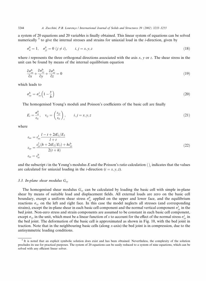
a system of 20 equations and 20 variables is finally obtained. This linear system of equations can be solvednumerically 5 to give the internal stresses and strains for uniaxial load in the i-direction, given by
r0ii ¼ 1; r0
jj ¼ 0 ðj 6¼ iÞ; i; j ¼ x; y; z ð18Þ
where i represents the three orthogonal directions associated with the axis x, y or z. The shear stress in theunit can be found by means of the internal equilibrium equation
orbxx
oxþorb
xy
oyþ orb
xz
oz¼ 0 ð19Þ
which leads to
rbxy ¼ r1
xy 1�
� yh
�ð20Þ
The homogenised Young’s moduli and Poisson’s coefficients of the basic cell are finally
Ei ¼r0ii
eii; mij ¼
ejjeii
� �i
; i; j ¼ x; y; z ð21Þ
where
exx ¼ e1xxl� t þ 2tE1=E3
lþ t
eyy ¼e2yyðhþ 2tE2=E3Þ þ hebyy
2ðt þ hÞezz ¼ ebzz
ð22Þ
and the subscript i in the Young’s modulus E and the Poisson’s ratio calculation ð Þi indicates that the valuesare calculated for uniaxial loading in the i-direction (i ¼ x; y; z).
3.3. In-plane shear modulus Gxy
The homogenised shear modulus Gxy can be calculated by loading the basic cell with simple in-planeshear by means of suitable load and displacement fields. All external loads are zero on the basic cellboundary, except a uniform shear stress r0
xy applied on the upper and lower face, and the equilibriumreactions rxy on the left and right face. In this case the model neglects all stresses (and correspondingstrains), except the in-plane shear in each basic cell component and the normal vertical component r1
yy in thebed joint. Non-zero stress and strain components are assumed to be constant in each basic cell component,except rxy in the unit, which must be a linear function of x to account for the effect of the normal stress r1
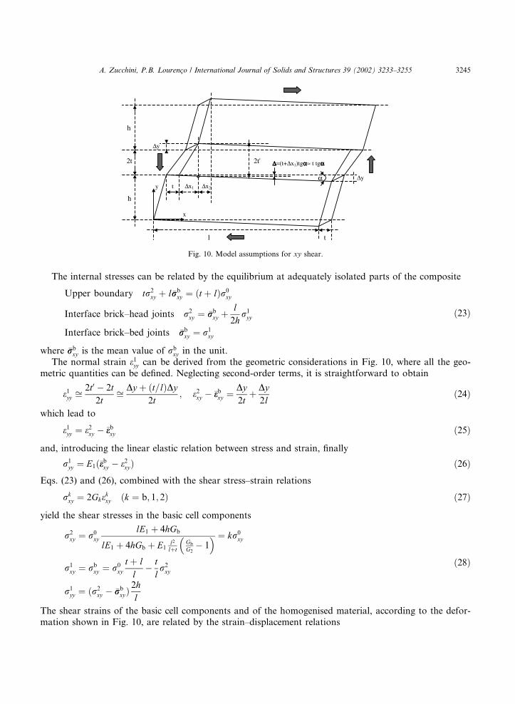
yy inthe bed joint. The deformation of the basic cell is approximated as shown in Fig. 10, with the bed joint intraction. Note that in the neighbouring basic cells (along x-axis) the bed joint is in compression, due to theantisymmetric loading conditions.
5 It is noted that an explicit symbolic solution does exist and has been obtained. Nevertheless, the complexity of the solution
precludes its use for practical purposes. The system of 20 equations can be easily reduced to a system of nine equations, which can be
solved with any efficient linear solver.
3244 A. Zucchini, P.B. Lourenc�o / International Journal of Solids and Structures 39 (2002) 3233–3255
The internal stresses can be related by the equilibrium at adequately isolated parts of the composite
Upper boundary tr2xy þ l�rrb
xy ¼ ðt þ lÞr0xy
Interface brick–head joints r2xy ¼ �rrb
xy þl2h
r1yy
Interface brick–bed joints �rrbxy ¼ r1
xy
ð23Þ
where �rrbxy is the mean value of rb
xy in the unit.The normal strain e1yy can be derived from the geometric considerations in Fig. 10, where all the geo-
metric quantities can be defined. Neglecting second-order terms, it is straightforward to obtain
e1yy ffi2t0 � 2t
2tffi Dy þ ðt=lÞDy
2t; e2xy � �eebxy ¼
Dy2t
þ Dy2l
ð24Þ
which lead to
e1yy ¼ e2xy � �eebxy ð25Þ
and, introducing the linear elastic relation between stress and strain, finally
r1yy ¼ E1ð�eebxy � e2xyÞ ð26Þ
Eqs. (23) and (26), combined with the shear stress–strain relations
rkxy ¼ 2Gke
kxy ðk ¼ b; 1; 2Þ ð27Þ
yield the shear stresses in the basic cell components
r2xy ¼ r0
xy
lE1 þ 4hGb
lE1 þ 4hGb þ E1l2lþt
Gb
G2� 1
� � ¼ kr0xy
r1xy ¼ rb
xy ¼ r0xy
t þ ll
� tlr2xy
r1yy ¼ ðr2
xy � �rrbxyÞ
2hl
ð28Þ
The shear strains of the basic cell components and of the homogenised material, according to the defor-mation shown in Fig. 10, are related by the strain–displacement relations
Fig. 10. Model assumptions for xy shear.
A. Zucchini, P.B. Lourenc�o / International Journal of Solids and Structures 39 (2002) 3233–3255 3245
e1xy ffi1
2
Dx12t
�� Dy
l
�; e2xy ffi
1
2
Dx2h
�þ Dy
t
�
�eebxy ffi1
2
Dx2h
�� Dy
l
�; exy ffi
ðDx1=2Þ þ Dx22ðhþ tÞ
ð29Þ
which lead to
exy ¼1
hþ tðl�eebxy
þ te2xyÞ
hlþ t
þ te1xy þ ðe2xy � �eebxyÞt2
lþ t
ð30Þ
The shear strains eixy in the above equation can be calculated from the shear stresses given in Eq. (28) bymeans of the elastic relations of Eq. (27), resulting, finally, in the homogenised shear modulus Gxy
Gxy ¼r0xy
2exy¼ lðt þ lÞðt þ hÞ
k tlðtþhÞG2
þ ðtþl�ktÞðlh�t2ÞGb
þ tðtþlÞðtþl�ktÞG1
ð31Þ
where k is defined in Eq. (28).
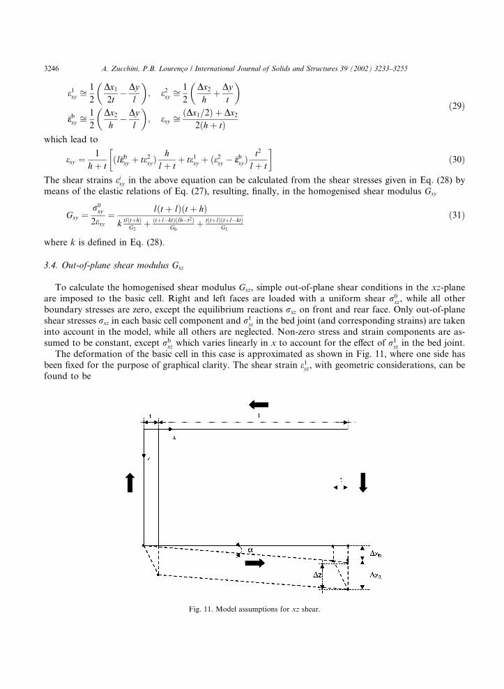
3.4. Out-of-plane shear modulus Gxz
To calculate the homogenised shear modulus Gxz, simple out-of-plane shear conditions in the xz-planeare imposed to the basic cell. Right and left faces are loaded with a uniform shear r0
xz, while all otherboundary stresses are zero, except the equilibrium reactions rxz on front and rear face. Only out-of-planeshear stresses rxz in each basic cell component and r1
yz in the bed joint (and corresponding strains) are takeninto account in the model, while all others are neglected. Non-zero stress and strain components are as-sumed to be constant, except rb
xz which varies linearly in x to account for the effect of r1yz in the bed joint.
The deformation of the basic cell in this case is approximated as shown in Fig. 11, where one side hasbeen fixed for the purpose of graphical clarity. The shear strain e1yz, with geometric considerations, can befound to be
Fig. 11. Model assumptions for xz shear.
3246 A. Zucchini, P.B. Lourenc�o / International Journal of Solids and Structures 39 (2002) 3233–3255
e1yz ¼1
2
Dz2t
ffi Dz2 � ðt=lÞDzb4t
ð32Þ
The following relations also hold
Interface brick–head joint r2xz ¼ �rrb
xz �ðl� tÞ2h
r1yz
Right boundary h �rrbxz
�þ ðl� tÞ
2hr1yz
�þ 2tr3
xz þ hr2xz ¼ 2ðt þ hÞr0
xz
Interface cross–bed joints r3xz ¼ r1
xz
Interface brick–bed joint Dzb ¼ Dz1
ð33Þ
By means of the shear stress–strain relations
rkxz ¼ 2Gke
kxz ðk ¼ b; 1; 2Þ ð34Þ
and of the kinematic relations
e1xz ffi1
2
Dz1l
; e2xz ffi1
2
Dz2t
; �eebxz ffi1
2
Dzbl
ð35Þ
Eqs. (32) and (33) yield
e1xz ¼ ebxz ¼ r0xz
t þ h2ðtG1 þ hGbÞ
e2xz ¼ ebxz4hGb þ ðl� tÞG1
4hG2 þ ðl� tÞG1
e1yz ¼1
2ðe2xz � ebxzÞ
ð36Þ
and the homogenised shear modulus can be finally found as
Gxz ¼r0xz
2exz¼ r0
xz
2
t þ 1
te2xz þ lebxz¼ ðt þ lÞðtG1 þ hGbÞ
ðt þ hÞ t 4hGbþðl�tÞG1
4hG2þðl�tÞG1þ l
� � ð37Þ
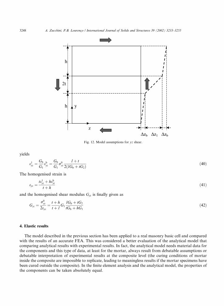
3.5. Out-of-plane shear modulus Gyz
The basic cell in this case is assumed to be in simple out-of-plane shear (in the plane yz) by means ofappropriate boundary conditions. The external load is a uniform shear stress r0
yz applied on upper andlower face of the basic cell, while equilibrium reactions ryz act on front and rear face, where the boundarycondition uy ¼ 0 is imposed. Only the shear stresses ryz (and corresponding strains) are taken into accountin the model. It can be argued, from the deformation shown in Fig. 12 (where one side has been fixed for thepurpose of graphical clarity), that
Upper boundary tr2yz þ lrb
yz ¼ ðt þ lÞr0yz
Interface brick–bed joints rbyz ¼ r1
yz
Interface brick–head joints ebyz ¼ e2yz
ð38Þ
Combining these equations with the stress–strain relations
rkyz ¼ 2Gke
kyz ðk ¼ b; 1; 2Þ ð39Þ
A. Zucchini, P.B. Lourenc�o / International Journal of Solids and Structures 39 (2002) 3233–3255 3247
yields
e1yz ¼Gb
G1
ebyz ¼Gb
G1
r0yz
lþ t2ðlGb þ tG2Þ
ð40Þ
The homogenised strain is
eyz ¼te1yz þ hebyzt þ h
ð41Þ
and the homogenised shear modulus Gyz is finally given as
Gyz ¼r0yz
2eyz¼ t þ h
t þ lG1
lGb þ tG2
tGb þ hG1
ð42Þ
4. Elastic results
The model described in the previous section has been applied to a real masonry basic cell and comparedwith the results of an accurate FEA. This was considered a better evaluation of the analytical model thatcomparing analytical results with experimental results. In fact, the analytical model needs material data forthe components and this type of data, at least for the mortar, always result from debatable assumptions ordebatable interpretation of experimental results at the composite level (the curing conditions of mortarinside the composite are impossible to replicate, leading to meaningless results if the mortar specimens havebeen cured outside the composite). In the finite element analysis and the analytical model, the properties ofthe components can be taken absolutely equal.
Fig. 12. Model assumptions for yz shear.
3248 A. Zucchini, P.B. Lourenc�o / International Journal of Solids and Structures 39 (2002) 3233–3255
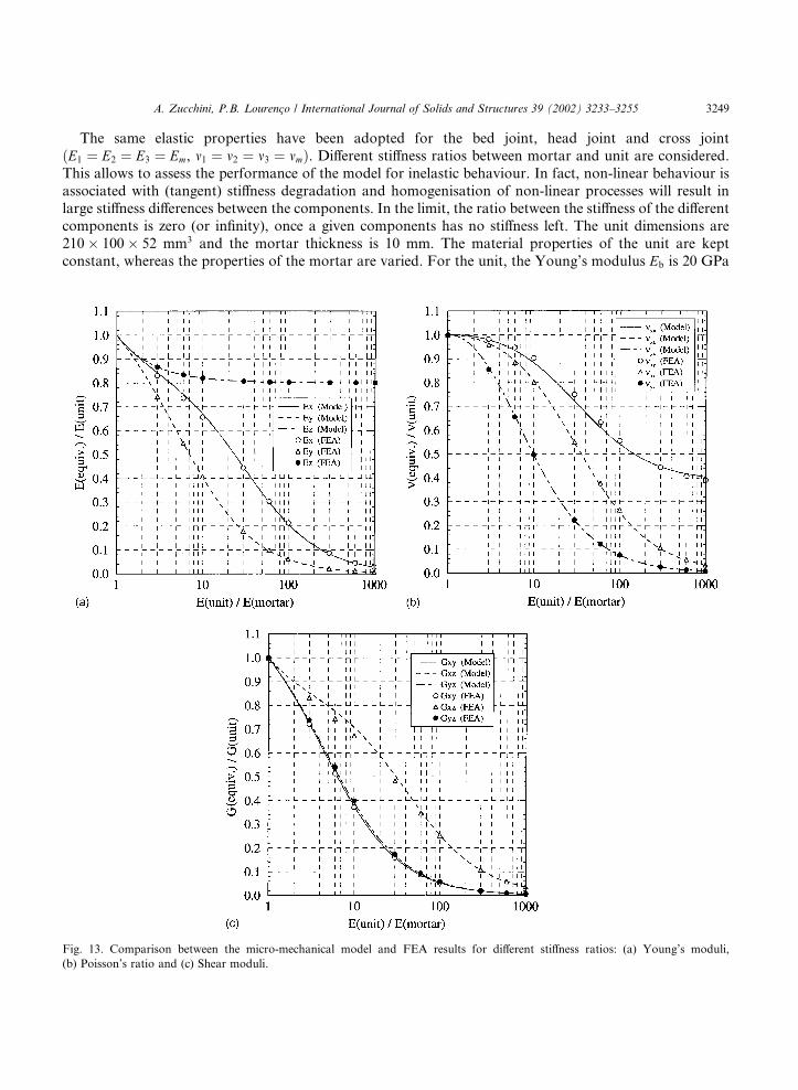
The same elastic properties have been adopted for the bed joint, head joint and cross jointðE1 ¼ E2 ¼ E3 ¼ Em, m1 ¼ m2 ¼ m3 ¼ mmÞ. Different stiffness ratios between mortar and unit are considered.This allows to assess the performance of the model for inelastic behaviour. In fact, non-linear behaviour isassociated with (tangent) stiffness degradation and homogenisation of non-linear processes will result inlarge stiffness differences between the components. In the limit, the ratio between the stiffness of the differentcomponents is zero (or infinity), once a given components has no stiffness left. The unit dimensions are210� 100� 52 mm3 and the mortar thickness is 10 mm. The material properties of the unit are keptconstant, whereas the properties of the mortar are varied. For the unit, the Young’s modulus Eb is 20 GPa
Fig. 13. Comparison between the micro-mechanical model and FEA results for different stiffness ratios: (a) Young’s moduli,
(b) Poisson’s ratio and (c) Shear moduli.
A. Zucchini, P.B. Lourenc�o / International Journal of Solids and Structures 39 (2002) 3233–3255 3249
and the Poisson’s ratio mb is 0.15. For the mortar, the Young’s modulus is varied to yield a ratio Eb=Em
ranging from 1 to 1000. The Poisson’s ratio mm is kept constant to 0.15.The adopted range of Eb=Em is very large (up to 1000), if only linear elastic behaviour of mortar is
considered. However, those high values are indeed encountered if inelastic behaviour is included. In suchcase, Eb and Em should be understood as linearised tangent Young’s moduli, representing a measure of thedegradation of the (tangent/secant) stiffness matrices utilised in the numerical procedures adopted to solvethe non-linear problem. Note that the ratio Eb=Em tends to infinity when softening of the mortar iscomplete and only the unit remains structurally active.
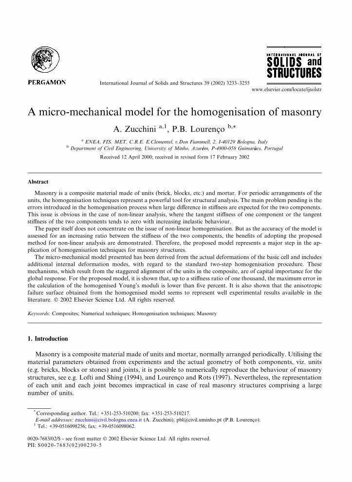
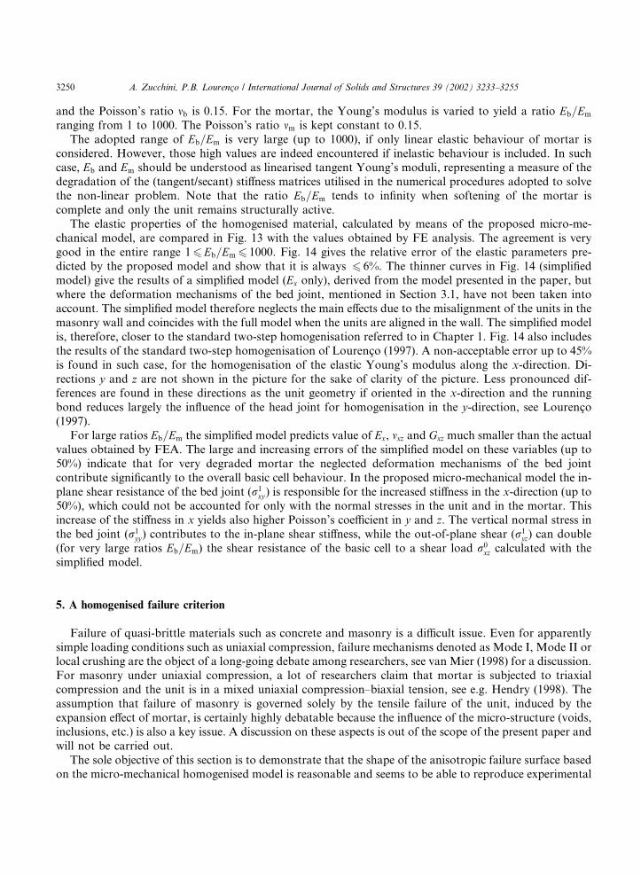
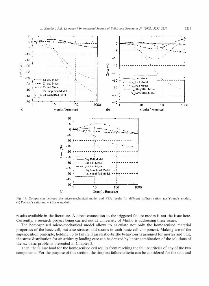
The elastic properties of the homogenised material, calculated by means of the proposed micro-me-chanical model, are compared in Fig. 13 with the values obtained by FE analysis. The agreement is verygood in the entire range 16Eb=Em 6 1000. Fig. 14 gives the relative error of the elastic parameters pre-dicted by the proposed model and show that it is always 6 6%. The thinner curves in Fig. 14 (simplifiedmodel) give the results of a simplified model (Ex only), derived from the model presented in the paper, butwhere the deformation mechanisms of the bed joint, mentioned in Section 3.1, have not been taken intoaccount. The simplified model therefore neglects the main effects due to the misalignment of the units in themasonry wall and coincides with the full model when the units are aligned in the wall. The simplified modelis, therefore, closer to the standard two-step homogenisation referred to in Chapter 1. Fig. 14 also includesthe results of the standard two-step homogenisation of Lourenc�o (1997). A non-acceptable error up to 45%is found in such case, for the homogenisation of the elastic Young’s modulus along the x-direction. Di-rections y and z are not shown in the picture for the sake of clarity of the picture. Less pronounced dif-ferences are found in these directions as the unit geometry if oriented in the x-direction and the runningbond reduces largely the influence of the head joint for homogenisation in the y-direction, see Lourenc�o(1997).
For large ratios Eb=Em the simplified model predicts value of Ex, mxz and Gxz much smaller than the actualvalues obtained by FEA. The large and increasing errors of the simplified model on these variables (up to50%) indicate that for very degraded mortar the neglected deformation mechanisms of the bed jointcontribute significantly to the overall basic cell behaviour. In the proposed micro-mechanical model the in-plane shear resistance of the bed joint (r1
xy) is responsible for the increased stiffness in the x-direction (up to50%), which could not be accounted for only with the normal stresses in the unit and in the mortar. Thisincrease of the stiffness in x yields also higher Poisson’s coefficient in y and z. The vertical normal stress inthe bed joint (r1
yy) contributes to the in-plane shear stiffness, while the out-of-plane shear (r1yz) can double
(for very large ratios Eb=Em) the shear resistance of the basic cell to a shear load r0xz calculated with the
simplified model.
5. A homogenised failure criterion
Failure of quasi-brittle materials such as concrete and masonry is a difficult issue. Even for apparentlysimple loading conditions such as uniaxial compression, failure mechanisms denoted as Mode I, Mode II orlocal crushing are the object of a long-going debate among researchers, see van Mier (1998) for a discussion.For masonry under uniaxial compression, a lot of researchers claim that mortar is subjected to triaxialcompression and the unit is in a mixed uniaxial compression–biaxial tension, see e.g. Hendry (1998). Theassumption that failure of masonry is governed solely by the tensile failure of the unit, induced by theexpansion effect of mortar, is certainly highly debatable because the influence of the micro-structure (voids,inclusions, etc.) is also a key issue. A discussion on these aspects is out of the scope of the present paper andwill not be carried out.
The sole objective of this section is to demonstrate that the shape of the anisotropic failure surface basedon the micro-mechanical homogenised model is reasonable and seems to be able to reproduce experimental
3250 A. Zucchini, P.B. Lourenc�o / International Journal of Solids and Structures 39 (2002) 3233–3255
results available in the literature. A direct connection to the triggered failure modes is not the issue here.Currently, a research project being carried out at University of Minho is addressing these issues.
The homogenised micro-mechanical model allows to calculate not only the homogenised materialproperties of the basic cell, but also stresses and strains in each basic cell component. Making use of thesuperposition principle, holding up to failure if an elastic–brittle behaviour is assumed for mortar and unit,the stress distribution for an arbitrary loading case can be derived by linear combination of the solutions ofthe six basic problems presented in Chapter 3.
Then, the failure load for the homogenised cell results from reaching the failure criteria of any of the twocomponents. For the purpose of this section, the simplest failure criteria can be considered for the unit and
Fig. 14. Comparison between the micro-mechanical model and FEA results for different stiffness ratios: (a) Young’s moduli,
(b) Poisson’s ratio and (c) Shear moduli.
A. Zucchini, P.B. Lourenc�o / International Journal of Solids and Structures 39 (2002) 3233–3255 3251
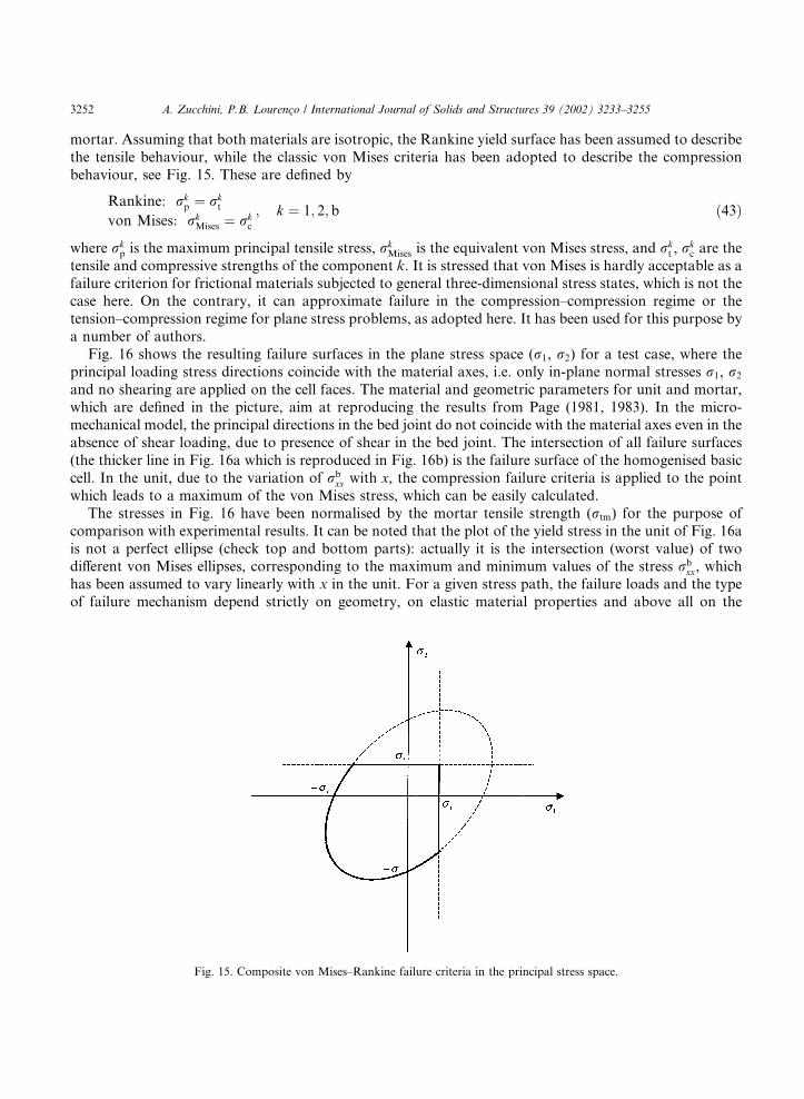
mortar. Assuming that both materials are isotropic, the Rankine yield surface has been assumed to describethe tensile behaviour, while the classic von Mises criteria has been adopted to describe the compressionbehaviour, see Fig. 15. These are defined by
Rankine: rkp ¼ rk
t
von Mises: rkMises ¼ rk
c
; k ¼ 1; 2; b ð43Þ
where rkp is the maximum principal tensile stress, rk
Mises is the equivalent von Mises stress, and rkt , r
kc are the
tensile and compressive strengths of the component k. It is stressed that von Mises is hardly acceptable as afailure criterion for frictional materials subjected to general three-dimensional stress states, which is not thecase here. On the contrary, it can approximate failure in the compression–compression regime or thetension–compression regime for plane stress problems, as adopted here. It has been used for this purpose bya number of authors.
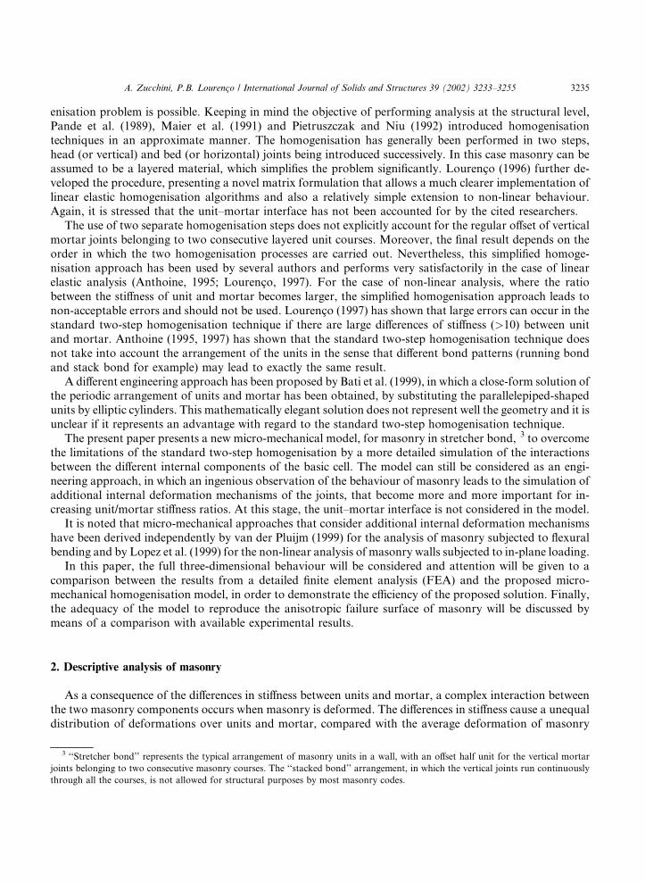
Fig. 16 shows the resulting failure surfaces in the plane stress space (r1, r2) for a test case, where theprincipal loading stress directions coincide with the material axes, i.e. only in-plane normal stresses r1, r2
and no shearing are applied on the cell faces. The material and geometric parameters for unit and mortar,which are defined in the picture, aim at reproducing the results from Page (1981, 1983). In the micro-mechanical model, the principal directions in the bed joint do not coincide with the material axes even in theabsence of shear loading, due to presence of shear in the bed joint. The intersection of all failure surfaces(the thicker line in Fig. 16a which is reproduced in Fig. 16b) is the failure surface of the homogenised basiccell. In the unit, due to the variation of rb
xx with x, the compression failure criteria is applied to the pointwhich leads to a maximum of the von Mises stress, which can be easily calculated.
The stresses in Fig. 16 have been normalised by the mortar tensile strength (rtm) for the purpose ofcomparison with experimental results. It can be noted that the plot of the yield stress in the unit of Fig. 16ais not a perfect ellipse (check top and bottom parts): actually it is the intersection (worst value) of twodifferent von Mises ellipses, corresponding to the maximum and minimum values of the stress rb
xx, whichhas been assumed to vary linearly with x in the unit. For a given stress path, the failure loads and the typeof failure mechanism depend strictly on geometry, on elastic material properties and above all on the
Fig. 15. Composite von Mises–Rankine failure criteria in the principal stress space.
3252 A. Zucchini, P.B. Lourenc�o / International Journal of Solids and Structures 39 (2002) 3233–3255
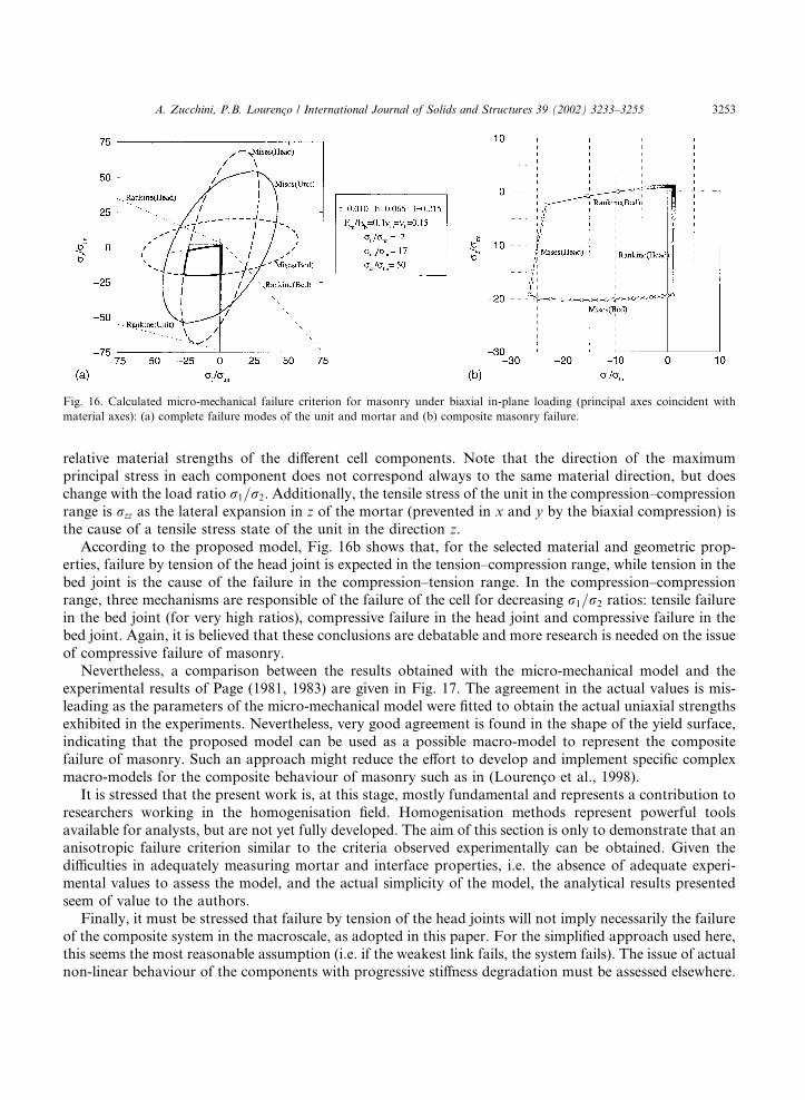
relative material strengths of the different cell components. Note that the direction of the maximumprincipal stress in each component does not correspond always to the same material direction, but doeschange with the load ratio r1=r2. Additionally, the tensile stress of the unit in the compression–compressionrange is rzz as the lateral expansion in z of the mortar (prevented in x and y by the biaxial compression) isthe cause of a tensile stress state of the unit in the direction z.
According to the proposed model, Fig. 16b shows that, for the selected material and geometric prop-erties, failure by tension of the head joint is expected in the tension–compression range, while tension in thebed joint is the cause of the failure in the compression–tension range. In the compression–compressionrange, three mechanisms are responsible of the failure of the cell for decreasing r1=r2 ratios: tensile failurein the bed joint (for very high ratios), compressive failure in the head joint and compressive failure in thebed joint. Again, it is believed that these conclusions are debatable and more research is needed on the issueof compressive failure of masonry.
Nevertheless, a comparison between the results obtained with the micro-mechanical model and theexperimental results of Page (1981, 1983) are given in Fig. 17. The agreement in the actual values is mis-leading as the parameters of the micro-mechanical model were fitted to obtain the actual uniaxial strengthsexhibited in the experiments. Nevertheless, very good agreement is found in the shape of the yield surface,indicating that the proposed model can be used as a possible macro-model to represent the compositefailure of masonry. Such an approach might reduce the effort to develop and implement specific complexmacro-models for the composite behaviour of masonry such as in (Lourenc�o et al., 1998).
It is stressed that the present work is, at this stage, mostly fundamental and represents a contribution toresearchers working in the homogenisation field. Homogenisation methods represent powerful toolsavailable for analysts, but are not yet fully developed. The aim of this section is only to demonstrate that ananisotropic failure criterion similar to the criteria observed experimentally can be obtained. Given thedifficulties in adequately measuring mortar and interface properties, i.e. the absence of adequate experi-mental values to assess the model, and the actual simplicity of the model, the analytical results presentedseem of value to the authors.
Finally, it must be stressed that failure by tension of the head joints will not imply necessarily the failureof the composite system in the macroscale, as adopted in this paper. For the simplified approach used here,this seems the most reasonable assumption (i.e. if the weakest link fails, the system fails). The issue of actualnon-linear behaviour of the components with progressive stiffness degradation must be assessed elsewhere.
Fig. 16. Calculated micro-mechanical failure criterion for masonry under biaxial in-plane loading (principal axes coincident with
material axes): (a) complete failure modes of the unit and mortar and (b) composite masonry failure.
A. Zucchini, P.B. Lourenc�o / International Journal of Solids and Structures 39 (2002) 3233–3255 3253
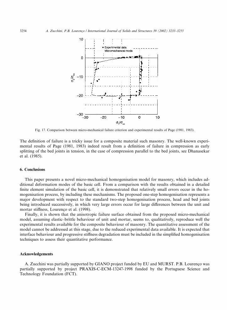
The definition of failure is a tricky issue for a composite material such masonry. The well-known experi-mental results of Page (1981, 1983) indeed result from a definition of failure in compression as earlysplitting of the bed joints in tension, in the case of compression parallel to the bed joints, see Dhanasekaret al. (1985).
6. Conclusions
This paper presents a novel micro-mechanical homogenisation model for masonry, which includes ad-ditional deformation modes of the basic cell. From a comparison with the results obtained in a detailedfinite element simulation of the basic cell, it is demonstrated that relatively small errors occur in the ho-mogenisation process, by including these mechanisms. The proposed one-step homogenisation represents amajor development with respect to the standard two-step homogenisation process, head and bed jointsbeing introduced successively, in which very large errors occur for large differences between the unit andmortar stiffness, Lourenc�o et al. (1998).
Finally, it is shown that the anisotropic failure surface obtained from the proposed micro-mechanicalmodel, assuming elastic–brittle behaviour of unit and mortar, seems to, qualitatively, reproduce well theexperimental results available for the composite behaviour of masonry. The quantitative assessment of themodel cannot be addressed at this stage, due to the reduced experimental data available. It is expected thatinterface behaviour and progressive stiffness degradation must be included in the simplified homogenisationtechniques to assess their quantitative performance.
Acknowledgements
A. Zucchini was partially supported by GIANO project funded by EU and MURST. P.B. Lourenc�o waspartially supported by project PRAXIS-C-ECM-13247-1998 funded by the Portuguese Science andTechnology Foundation (FCT).
Fig. 17. Comparison between micro-mechanical failure criterion and experimental results of Page (1981, 1983).
3254 A. Zucchini, P.B. Lourenc�o / International Journal of Solids and Structures 39 (2002) 3233–3255
References
Anthoine, A., 1995. Derivation of the in-plane elastic characteristics of masonry through homogenization theory. International
Journal of Solids and Structures 32 (2), 137–163.
Anthoine, A., 1997. Homogenisation of periodic masonry: plane stress, generalised plane strain or 3D modelling? Communications in
Numerical Methods in Engineering 13, 319–326.
Bakhvalov, N., Panasenko, G., 1989. Homogenization: averaging processes in periodic media. Kluwer Academic Publishers,
Dordrecht, The Netherlands.
Bati, S.B., Ranocchiai, G., Rovero, L., 1999. A micromechanical model for linear homogenization of unit masonry. Materials and
Structures 32, 22–30.
Besdo, D., 1985. Inelastic behaviour of plane frictionless block systems described as Cosserat media. Archives in Mechanics 37 (6),
603–619.
Dhanasekar, M., Page, A.W., Kleeman, P.W., 1985. The failure of brick masonry under biaxial stresses. Proceedings from the
Institution of Civil Engineers––Part 2 79, 295–313.
Hendry, A.W., 1998. Structural Masonry. Macmillan Press, Basingstoke, UK.
Lofti, H.R., Shing, P.B., 1994. Interface model applied to fracture of masonry structures. Journal of Structural Engineering ASCE 120
(1), 63–80.
Lopez, J., Oller, S., O~nnate, E., Lubliner, J., 1999. A homogeneous constitutive model for masonry. International Journal for Numerical
Methods in Engineering 46, 1651–1671.
Lourenc�o, P.B., 1996. A matrix formulation for the elastoplastic homogenisation of layered materials. Mechanics of Cohesive-
Frictional Materials 1, 273–294.
Lourenc�o, P.B., 1997. On the use of homogenisation techniques for the analysis of masonry structures. Masonry International 11 (1),
26–32.
Lourenc�o, P.B., Rots, J.G., 1997. A multi-surface interface model for the analysis of masonry structures. Journal of Engineering
Mechanics ASCE 123 (7), 660–668.
Lourenc�o, P.B., Rots, J.G., Blaauwendraad, J., 1998. Continuum model for masonry: parameter estimation and validation. Journal of
Structural Engineering ASCE 124 (6), 642–652.
Maier, G., Papa, E., Nappi, A., 1991. On damage and failure of unit masonry. In: Experimental and numerical methods in earthquake
engineering. Balkema, Brussels, pp. 223–245.
van Mier, J.G.M., 1998. Failure of concrete under uniaxial compression: an overview. In: Fracture mechanics of concrete structures,
vol. 2. Aedificatio, Freiburg, pp. 1169–1182.
M€uuhlhaus, H.-B., 1993. Continuum models for layered soil and blocky rock. In: Comprehensive rock engineering, Vol. 2. Pergamon
Press, Oxford.
Page, A.W., 1981. The biaxial compressive strength of brick masonry. Proceedings from the Institution of Civil Engineers––Part 2 71,
893–906.
Page, A.W., 1983. The strength of brick masonry under biaxial compression–tension. International Journal of Masonry Construction 3
(1), 26–31.
Pande, G.N., Liang, J.X., Middleton, J., 1989. Equivalent elastic moduli for unit masonry. Computers and Geotechnics 8, 243–265.
Pietruszczak, S., Niu, X., 1992. A mathematical description of macroscopic behavior of unit masonry. International Journal of Solids
and Structures 29 (5), 531–546.
van der Pluijm, R., 1999. Out of plane bending of masonry: behaviour and strength. Ph.D. Dissertation, Eindhoven University of
Technology, The Netherlands.
Urbanski, A., Szarlinski, J., Kordecki, Z., 1995. Finite element modeling of the behavior of the masonry walls and columns by
homogenization approach. In: Computer methods in structural masonry––3. Books and Journals International, Swansea, pp. 32–
41.
A. Zucchini, P.B. Lourenc�o / International Journal of Solids and Structures 39 (2002) 3233–3255 3255