Embed Size (px)
Citation preview
Micro Electrochemical Machining of 3D Micro Structure Using Dilute Sulfuric Acid
B. H. Kim’, C. W. Na’, Y. S. Lee’, D. K. Choi2, C. N. Chu’(2)
School of Mechanical and Aerospace Engineering, Seoul National University, Seoul, Korea
Department of Precision Mechanical Engineering, Kangnung National University, Kangnung, Korea
1
2
Abstract Micro electrochemical machining (ECM) using ultra short pulses with tens of nanosecond duration is presented. 0.1 M sulfuric acid was used as electrolyte and 3D micro structures were machined on stainless steel. To prevent taper, a disk-type electrode was introduced. Using the disk-type electrode, taper could be eliminated. To improve productivity, multiple electrodes were applied and multiple structures were machined simultaneously. Since the wear of tool electrode is negligible in ECM, micro wire can be used as tool electrode. Using a platinum wire electrode with 10 pm diameter, various 3D features were machined on stainless steel plate.
Keywords: Electro chemical machining (ECM), Electrode, Micro machining
1 INTRODUCTION Electrochemical machining (ECM) has been widely used in the manufacturing industry because hard metals can be machined regardless of the mechanical property of a workpiece. However, since the gap between an electrode and the workpiece is large, ECM has not been used for the micro machining. Recently, Schuster et al. showed that the machining gap can be reduced to a few micrometers by applying ultra short pulses and fabricated micro structures from stainless steel [ I ] . In contrast to micro electrical discharge machining (EDM) which suffers from tool wear, micro ECM can be applied to the machining without the compensation of tool wear [2]. This characteristic also allows much smaller tool electrodes, for example, sub- micrometer-scale electrodes, in ECM [3]. However, for the machining of stainless steel, high concentration electrolytes have been used. Recently, it was reported that less toxic and dilute electrolyte, 0.1 M H2SO4 can be applied for the machining of stainless steel [4, 51. In this paper, the application of micro ECM with ultra short pulses is presented. Various micro structures were fabricated on stainless steel by using micro electrode and micro wire in 0.1 M H2SO4.
2 MICRO ELECTROCHEMICAL MACHINING
2.1 Experimental system As shown in Figure 1, the experimental system consists of an electrochemical cell, a pulse generator, XYZ stages and an oscilloscope. For a tool electrode, tungsten carbide was machined to micro shafts with 10 - 50 pm in diameter by electrochemical etching or micro EDM. EDM circuits and an EDM bath are attached to the same ECM machine. A workpiece is 15 mm x 15 mm 304 stainless steel with 300 pm thickness. After mechanical polishing, the workpiece is immersed in 0.1 M H2SO4. Since the current from the high frequency pulse generator is very small, it is necessary to concentrate the current to the machining area. The current density could be increased by maintaining the height of electrolyte from the workpiece to a few hundreds of micrometers (Figure 1). During the machining, the potential between the tool electrode and the workpiece is monitored.
If the tool electrode contacts the workpiece, the potential drops. The potential drop is used for controlling the feed of tool electrode. An electric balance electrode is attached to control the potential between the workpiece and electrolyte.
Figure 1: System for micro ECM
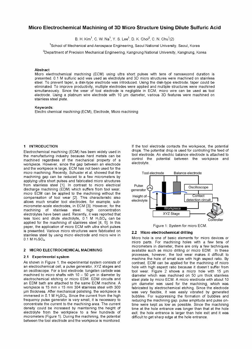
2.2 Micro electrochemical drilling Micro hole is one of basic elements for micro devices or micro parts. For machining holes with a few tens of micrometers in diameter, there are only a few techniques available such as micro drilling or micro EDM. In these processes, however, the tool wear makes it difficult to machine the hole of small size with high aspect ratio. By contrast, ECM can be applied for the machining of micro hole with high aspect ratio because it doesn’t suffer from tool wear. Figure 2 shows a micro hole with 15 pm diameter which was machined on 50 pm thick stainless steel plate by micro ECM. A micro electrode with about 10 pm diameter was used for the machining, which was fabricated by electrochemical etching. Since the electrode was very flexible, it was easily vibrated by generated bubbles. For suppressing the formation of bubbles and reducing the machining gap, pulse amplitude and pulse on- time were kept as low as possible. Since the machining time at the hole entrance was longer than that at the hole exit, the hole entrance is larger than hole exit and it was difficult to get sharp edge at the hole entrance.
Figure 2: Micro hole machined by ECM (a) hole entrance, (b) hole exit (304 SS, 0 15 pm, 50 pm depth, 5 V, 40 ns, 0.05 pm/sec).
2.3 Simulation In machining of micro holes, the change of machining gap was simulated according to the machining time and pulse on-time. Figure 3 shows an electric model for the electrode and the workpiece which are immersed in electrolyte [6, 71. The double layer at the interface of the electrolyte and the electrode can be considered as equivalent electrical circuits that consist of resistors and capacitors. Since electrolyte resistance (R,) is the product of the specific electrolyte resistivity (p) and the gap between the electrode and the workpiece (d), the charging time constant for double layer (z) is:
z = pcd (1 1 where c is the specific capacitance of double layer. When pulses were applied with on-time voltage of Qo, the charged potential of the double layer (Qc) is:
Since the pulse off-time voltage doesn’t cause the dissolution and it is very low relative to pulse on-time voltage, charged potential (Qc) can be considered as over- potential (q) . From the Butler-Volmer equation, during the pulse on-time, reaction current (11 is:
i = io e x p ( af 7 ) = io e x p a f -- [ ; : I (3)
where io is the exchange current density, and a is the transfer coefficient and f = f /RT , where f is the Faraday constant, R is the gas constant, and Tis the temperature. Since the reaction rate (v) is proportional to the current (v = i / z f , where z is the stoichiometric number), the dissolution rate (0 is:
1 t i = -j: -dt
tpeviod zF
= A”[ e x p [ B 91 - 11 440
(4)
where fpenod is pulse period, fp is pulse on-time The dissolved amount can be obtained by integrating equation (4) over machining time. The change of the machining gap is calculated from the dissolved amount. During the initial machining when the distance between the
tool and the workpiece is very small, the dissolution rate is limited by ion diffusion rate. Therefore, the ion diffusion should be considered for the initial machining gap.
Figure 3: The double layer model [6].
Figure 4 shows the simulation of the machining gap and the experimental data. The experimental data were obtained as follows. Micro holes with 10 pm depth were machined by using pulse with 6 V and 60 ns pulse on-time and the tool electrode was positioned at 10 pm depth for a specific duration. After the machining, the machining gap was estimated by measuring the tool diameter and the hole diameters. From equation (4), dissolution rate is determined by the parameters as shown in Table 1. Unknown parameters are the exchange current density and the specific capacitance of double layer. Typically, c is in the range of 10 to 40 pF/cm2. In order to fit a simulated data to the experimental data of 60 ns pulse on-time, c and io were determined to 13 pF/cm2 and 1.7 mA/cm2, respectively. Using the determined parameters, the change of machining gap was simulated with different pulse on- times, 100 ns and 150 ns. As shown in Figure 4, the simulated data fit well to the experimental data. In the initial stage of machining, the experimental data show some discrepancy because the dissolution rate is affected by the ion diffusion and the bubbles prevent flushing of electrolyte.
Figure 4: The change of machining gap according to pulse on-time and machining time.
Table 1: Parameters for simulation
time or current amplifier are necessary. More studies about the effect of machining area on the machining rate are required,
2.4 Micro electrochemical milling Micro ECM was applied to fabricate 3D structures through the electrochemical milling process. For the electrolyte flushing, layer-by-layer machining was applied. With dilute and less toxic electrolyte, 0.1 M H2SO4, micro structures with good surface quality (R, 0.28 pm) were machined [5 ] . Figure 5 shows a micro hemisphere on the top of a cylinder. This structure was machined in three steps. As the rough cut, the cylinder was machined and the hemisphere with 100 pm diameter was machined on the cylinder. As the finish cut, the hemisphere with 60 pm diameter was machined. In the finish cut, the material was removed with verv fast feedrate. 20 um/s. because the . . amount of removed material is' quite small. Since the
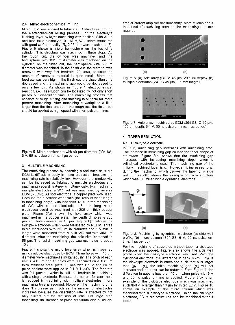
decreased and the machining gap could be decreased to feedrate was very high in the finish cut, the dissolution time Figure 6 : (a) hole array (cu, 0 45 pm1 2oo pm depth), (b)
multiple electrodes (wcl 35 prnl mm length). only a few pm. As shown in-Fjgure 4, electrochemical reaction, i.e., dissolution can be localized by not only short pulses but dissolution time. The machining process that consists of rough cutting and finishing is suitable for more precise machining. After machining a workpiece a little larger than the final shape in the rough cut, the finish cut should be applied at high speed with short pulse on-time.
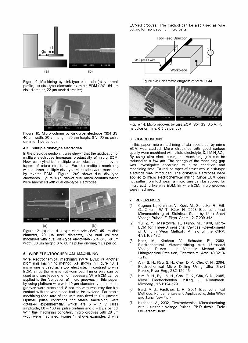
Figure 7: Hole array machined by ECM (304 SS, 0 40 pm, 100 pm depth, 6.1 V, 60 ns pulse on-time, 1 ps period).
Figure 5: Micro hemisphere with 60 pm diameter (304 SS, 6 V, 60 ns pulse on-time, 1 ps period).
3 MULTIPLE MACHINING The machining process by scanning a tool such as micro ECM is difficult to apply in mass production because the machining rate is relatively low. However, the productivity can be increased by fabricating multiple electrodes and machining several features simultaneously. For machining multiple electrodes, a WC rod was machined by reverse EDM (REDM). As tool electrode, a copper plate was used. Because the electrode wear ratio (the ratio of wear length to machining length) was less than 12 % in the machining of WC with copper electrode, 1.5 mm long micro electrodes could be machined with 200 pm thick copper plate. Figure 6(a) shows the hole array which was machined in the copper plate. The depth of holes is 200 pm and hole diameter is 45 pm. Figure 6(b) shows the multiple electrodes which were fabricated by REDM. Three micro electrodes with 35 pm in diameter and 1.5 mm in length were machined from a bulk WC rod with 300 pm diameter. After the machining, the hole size increased to 55 pm. The radial machining gap was estimated to about 10 pm. Figure 7 shows the micro hole array which is machined using multiple electrodes by ECM. Three holes with 40 pm diameter were machined simultaneously. The pitch of each row is 200 pm and 15 holes were machined on a 100 pm thick stainless steel plate. Pulses with 6.1 V and 60 ns pulse on-time were applied in 0.1 M H2SO4. The feedrate was 0.1 pm/sec, which is half the feedrate in machining with a single electrode. Because the current for each hole is reduced in machining with multiple electrodes, more machining time is required. However, the machining time doesn't increase as much as the number of electrodes increases because the dissolution rate is affected by not only current but the diffusion of ions. For large area machining, an increase of pulse amplitude and pulse on-
4 TAPER REDUCTION
4.1 Disk-type electrode In ECM, machining gap increases with machining time. The increase in machining gap causes the taper shape of structures. Figure 8(a) shows that the machining gap increases with increasing machining depth when a cylindrical electrode is used. The machining gap of the initially machined layer is go. However, it increases to gl during the machining, which causes the taper of a side wall. Figure 8(b) shows the example of micro structure which was EC milled with a cylindrical electrode.
Figure 8: Machining by cylindrical electrode (a) side wall profile, (b) micro column (304 SS, 6 V, 60 ns pulse on- time, 1 ps period). For the machining of structures without taper, a disk-type electrode was applied. Figure 9(a) shows the side wall profile when the disk-type electrode was used. With the cylindrical electrode, the difference in gaps is (9, - go). If the disk-type electrode is machined such that d is larger than (9, - go), the initial machining gap (go) will not increase and the taper can be reduced. From Figure 4, the difference in gaps is less than 10 pm when pulse with 6 V and 60 ns pulse on-time is applied. Figure 9(b) is an example of the disk-type electrode which was machined such that d is larger than 10 pm by micro EDM. Figure 10 shows an example of the micro column which was machined with a disk-type electrode. Using the disk-type electrode, 3D micro structures can be machined without taper.
ECMed grooves. This method can be also used as wire cutting for fabrication of micro parts.
Figure 9: Machining by disk-type electrode (a) side wall profile, (b) disk-type electrode by micro EDM (WC, 54 pm disk diameter, 22 pm neck diameter).
Figure 10: Micro column by disk-type electrode (304 SS, 40 pm width, 20 pm length, 85 pm height, 6 V, 60 ns pulse on-time, 1 ps period).
4.2 Multiple disk-type electrodes In the previous section, it was shown that the application of multiple electrodes increases productivity of micro ECM. However, cylindrical multiple electrodes can not prevent tapers of micro structures. For the multiple machining without taper, multiple disk-type electrodes were machined by reverse EDM. Figure 12(a) shows dual disk-type electrodes. Figure 12(b) shows dual micro columns which were machined with dual disk-type electrodes.
Figure 12: (a) dual disk-type electrodes (WC, 45 pm disk diameter, 20 pm neck diameter), (b) dual columns machined with dual disk-type electrodes (304 SS, 58 pm width, 83 pm height, 6 V, 60 ns pulse on-time, 1 ps period).
5 WIRE ELECTROCHEMICAL MACHINING Wire electrochemical machining (Wire ECM) is another promising machining method. As shown in Figure 13, a micro wire is used as a tool electrode. In contrast to wire EDM, since the wire is not worn out, thinner wire can be used and wire feeding is not necessary. Wire ECM can be applied to the fabrication of micro grooves. In this paper, by using platinum wire with 10 pm diameter, various micro grooves were machined. Since the wire was very flexible, contact with the workpiece had to be avoided. For stable machining feed rate of the wire was fixed to 0.1 pm/sec. Optimal pulse conditions for stable machining were obtained experimentally, which are 6 - 7 V pulse amplitude, 60 - 100 ns pulse on-time and 6 - 9 ps period. With this machining condition, micro grooves with 20 pm width were machined. Figure 14 shows examples of wire
Figure 13: Schematic diagram of Wire ECM.
Figure 14: Micro grooves by wire ECM (304 SS, 6.5 V, 75 ns pulse on-time, 6.5 ps period).
6 CONCLUSIONS In this paper, micro machining of stainless steel by micro ECM was studied. Micro structures with good surface quality were machined with dilute electrolyte, 0.1 M H2S04. By using ultra short pulse, the machining gap can be reduced to a few pm. The change of the machining gap was investigated according to pulse condition and machining time. To reduce taper of structures, a disk-type electrode was introduced. The disk-type electrodes were applied to micro electrochemical milling. Since ECM does not suffer from tool wear, a micro wire can be applied for micro cutting like wire EDM. By wire ECM, micro grooves were machined.
7 REFERENCES Cagnon, L., Kirchner, V., Kock, M., Schuster, R., Ertl, G., Gmelin, W. T., Kuck, H., 2003, Electrochemical Micromachining of Stainless Steel by Ultra Short Voltage Pulses, Z. Phys. Chem., 217:299-313. Yu, Z. Y., Masuzawa, T., Fujino, M., 1998, Micro- EDM for Three-Dimensional Cavities -Development of Uniform Wear Method-, Annals of the CIRP,
Kock, M., Kirchner, V., Schuster, R., 2003, Electrochemical Micromachining with Ultrashort Voltage Pulses - a Versatile Method with Lithographical Precision, Electrochim. Acta, 48:3213- 321 9. Ahn, S. H., Ryu, S. H., Choi, D. K., Chu, C. N., 2004, Electrochemical Micro Drilling Using Ultra Short Pulses, Prec. Eng., 28/2: 129-134. Kim, B. H., Ryu, S. H., Choi, D. K., Chu, C. N., 2005, Micro Electrochemical Milling, J. Micromech. Microeng., 15/1:124-129. Bard, A. J., Faulkner, L. R., 2001, Electrochemical Methods, Fundamentals and Applications, John Wiley and Sons, New York. Kirchner, V., 2002, Electrochemical Microstructuring with Ultrashort Voltage Pulses, Ph.D thesis, Freie Universitat Berlin.
47/1: 169-1 72.


![(GXFDWLRQ CHEMISTRY 0620/43 - … (0620)/0620_w17_qp_43.pdfWrite a chemical equation for the reaction..... [1] (ii) When iron(III) oxide is added to dilute sulfuric acid, an aqueous](https://img.pdfslide.us/doc/110x75/5a9f0b037f8b9a67178c4470/pdfgxfdwlrq-chemistry-062043-06200620w17qp43pdfwrite-a-chemical.jpg)