Embed Size (px)
Citation preview
Mia3d
Intra-oral 3D Imaging System
Operator’s Manual
The densys3D system comprises an intra-oral scanner and a third party CAD/CAM workstation at the dental lab or central production. The scanning process is straightforward and simple, guided by visual and audible prompts. A complete scan takes just a few minutes, after which a digital file is transferred to a dental lab for completion of the restoration.

Copyright © 2012 densys3D Ltd. All rights reserved.
Manual Revision Level: 12
Manual Revision Date: August 2016
Authorized Representative in the European Union:
Wim van den Brink
Gerrit van der Vennstraat 84HS
1077 EL Amsterdam, The Netherlands
Tel: +31-(0)(20)-811-0550
Fax: +31-842-2131-42
Densys3D has the CE Mark approval and the ISO (International Organization for
Standardization) 9001:2008 and ISO 13485:2003, as well as the FDA approval
0473
This product is covered by one or more of the following patents as
well as a number of pending patents:
US6,402,707, US7,724,932, US7,330,577, JAP 5106418, US 8665257,
US 9222768,
Mia3d Operator’s Manual
February 2016 Page 3 ©densys3D Ltd
TABLE OF CONTENTS INTRODUCTION ......................................................................................................................... 5
Preface ......................................................................................................................................... 5
Conventions ................................................................................................................................. 5
USER LICENSE AGREEMENT ..................................................................................................... 6
Indications for use ....................................................................................................................... 6
DENSYS3D HARDWARE ............................................................................................................ 7
Wand Hardware Description ..................................................................................................... 9
Wand Physical Description ........................................................................................................ 9
Work Station Description ......................................................................................................... 10
Safety Standards ....................................................................................................................... 10
Electrical Hazards ..................................................................................................................... 10
Operational Environment ......................................................................................................... 12
Non-operational Environment ................................................................................................. 14
Disinfection and Cleaning ........................................................................................................ 14
Biocompatibility ......................................................................................................................... 15
CAUTION ................................................................................................................................... 16
INSTALLATION ........................................................................................................................ 17
Unpacking and Inspection ....................................................................................................... 17
MIA3D OPERATING INSTRUCTIONS ......................................................................................... 18
Principal Navigation Aids ......................................................................................................... 18
Wizard Page Tabs .................................................................................................................... 18
Pre-Scan setup .......................................................................................................................... 19
Activating the Application ......................................................................................................... 19
Patient Selection ....................................................................................................................... 20
Mia3d Operator’s Manual
February 2016 Page 4 ©densys3D Ltd
Restoration ................................................................................................................................. 22
Pre-Scan Setup ......................................................................................................................... 23
Scan Screen .............................................................................................................................. 26
Help Tag ......................................................................................... Error! Bookmark not defined.
Preview ....................................................................................................................................... 28
Scanning ..................................................................................................................................... 29
Audio ............................................................................................... Error! Bookmark not defined.
Implants – Scan Bodies ........................................................................................................... 32
Scan Dialog Screen .................................................................................................................. 34
Finalize Last Scan ..................................................................................................................... 35
Edge Marking ............................................................................................................................. 36
Defining the Edge ..................................................................................................................... 37
Scan History ............................................................................................................................... 40
View............................................................................................................................................. 42
Bite .............................................................................................................................................. 43
Scan Completion / Inserting Missing Areas .......................................................................... 46
Exporting Scans ........................................................................................................................ 49
Exit Screen ................................................................................................................................. 54
Contact Information .................................................................................................................. 56
Mia3d Operator’s Manual
February 2016 Page 5 ©densys3D Ltd
Introduction
This document describes how to operate the densys3D Mia3d Intra Oral 3D Imaging System,
from now on referred to as Mia3d.
The Mia3d system package includes the densys3D intra oral camera, also known as the wand.
The wand and supporting hardware, software and accessories are a complete stand-alone system
for measuring teeth and producing an extremely accurate three dimensional virtual model. This
information is used in the construction of dental prosthetics.
Results are available in real time and are saved within the system. The virtual model can be used
in the clinic or exported via email to a laboratory for prosthetic production by dental CAD/CAM
machines.
NOTE: This User Manual can be received in French, by contacting
Ce manuel d'utilisation peuvent être reçus en français, en communiquant avec
Preface
This document is divided into three sections:
1. System description
2. Installation
3. Mia3d operating instructions
Conventions
To alert the reader to information essential for the safe and proper use of the equipment the
following warning symbols are used:
NOTE: Text presented in this manner presents clarifying information,
specific instructions, commentary, sidelights, or interesting points of
information.
CAUTION: Text presented in this manner indicates that failure to follow
directions could result in damage to equipment or loss of information.
WARNING: Text presented in this manner indicates that failure to follow
directions could result in harm to people.

Mia3d Operator’s Manual
February 2016 Page 6 ©densys3D Ltd
User License Agreement
The use of the densys3D Mia3d intra Oral Imaging System and applications are conditional on
acceptance of the license agreement and legal obligations as specified by densys3D.
Indications for use
The densys3D MIA3d intra oral scanning system and accessories is intended to provide a 3D view
of the mouth before and after the dental procedure, and to assist the dentist in the construction of
dental prosthetics.
Mia3d Operator’s Manual
February 2016 Page 7 ©densys3D Ltd
Densys3D Hardware
The Densys3D wand package comes as follows
A box containing A wand with cable A wand stand A foot pedal Scan Spray Scan separator
The hardware can comprise two possible configurations:
I. A Configuration - Trolley
1. Stand-alone unit with trolley
2. LCD display unit
3. Keyboard and mouse
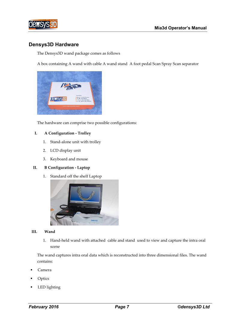
II. B Configuration - Laptop
1. Standard off the shelf Laptop
III. Wand
1. Hand-held wand with attached cable and stand used to view and capture the intra oral
scene
The wand captures intra oral data which is reconstructed into three dimensional files. The wand
contains:
Camera
Optics
LED lighting
Mia3d Operator’s Manual
February 2016 Page 8 ©densys3D Ltd
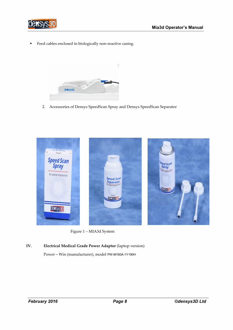
Feed cables enclosed in biologically non-reactive casing.
2. Accessories of Densys SpeedScan Spray and Densys SpeedScan Separator
Figure 1 – MIA3d System
IV. Electrical Medical Grade Power Adaptor (laptop version)
Power – Win (manufacturer), model PW-M160A-1Y190H
Mia3d Operator’s Manual
February 2016 Page 9 ©densys3D Ltd
Wand Hardware Description
Hand piece is impervious to fluid entry. It is made of material that is non-biological tissue reactive. It
weighs less than 200 grams and easily fits into the oral cavity whilst leaving room for the hand to grip
the wand end extra-orally.
The hardware specifications are as follows:
Optic system with glass lenses and glass optics.
Video:
o Transfer: Color or monochrome real time image acquisition from the wand camera on a
continuous basis.
o Transfer rate: Multi Frames per Second (FPS).
o Format: Composite Signal from the camera.
o Focus Range: 0mm – 18 mm.
o FOV: 16mm x 9mm.
o Light Source: LED.
o Pixel size 5 microns
o Resolution: 1280 X 1024 pixels.
Connection to the PC / Laptop: USB3
Input power: specialized USB 3.0 cable
Disposable cover of the viewing window.
Wand Physical Description
The wand’s weight and appearance are as follows:
Shape – the handpiece is characterized by a lack of sharp edges or rigid surfaces so the patients’
mouth can’t be harmed.
Weight – approx 200 grams without the cable.
Handle size – 20 mm by 18mms at the intra oral tip
Cable length – 1.8 m
Mia3d Operator’s Manual
February 2016 Page 10 ©densys3D Ltd
Work Station Description
The minimum hardware specifications are as follows:
Computer/Laptop
Processor: Intel Core i7
Memory: 8 GB
Power Supply: 500W medical grade - computer work station/ 140W medical grade
adaptor -laptop
GPU: NVidia GTX 670/970M
Hard disc/SSD: 500 GB
System Connections
Wand: specialised USB3.
Communication: Wired Ethernet or Wi-Fi connection
NOTE: The Wand includes a stand with a calibration step
Safety Standards
NOTE: The wand is IP5X level dust protected and has a handle that gives the
operator a secure grip
EMC – The system complies with the requirements of the EN 60601-1-2 standard.
Safety – The system complies with the requirements of the EN 60601-1 standard.
Electrical Hazards
NOTE: The device is supplied with a medical grade power adaptor and cables
as listed below, and maybe only be used when the supplied power adaptor
Mia3d Operator’s Manual
February 2016 Page 11 ©densys3D Ltd
NOTE: The device may only be used when the supplied power adaptor is
inserted directly in to the mains outlet.
NOTE: Do not change the power cable to the mains outlet
NOTE: Do not use an interface or adaptor to insert several electrical
appliances in the same outlet with the device
The device has been tested and found to comply with the limits for medical devices under the IEC
60601-1; 2005 & EN 60601-1; 2006, & EN/IEC 60601-1-2; 2007 standards. These limits are designed
to provide reasonable protection against harmful interference in a typical clinical installation. This
device generates, uses, and can radiate radio frequency energy. If not installed and used in
accordance with the instructions, it may cause harmful interference to other devices in the
vicinity. However, it should be noted that interference to other devices is not necessarily caused
by this instrument but may come from another source. Whether or not this device is interfering
with other devices can be easily determined by turning it off and on.
The user is encouraged to try to correct the interference by one or more of the following measures:
Reorient or relocate the receiving device.
Increase the separation between the devices.
Connect the device into an outlet on a circuit different from that which was previously used.
Consult Densys3D for help.
Interference to the device may be caused by portable and mobile RF communication equipment.
In case of an interruption, check that the interruption is not caused by communication equipment
operating in the vicinity.
Use of the system with any accessory, transducer or cable other than those specified may result in
increased EMISSIONS or decreased IMMUNITY than those specified.
Electrical Specifications:
Class II equipment
Mia3d Operator’s Manual
February 2016 Page 12 ©densys3D Ltd
The equipment may only be used with the medical electrical power supply included,
which is one of the two models listed here below.
Power – Win (manufacturer), model PW-M160A-1Y190H
Type BF applied part
No protection against ingress of water (IPX0)
Equipment not suitable for use in the presence of flammable mixtures
The unit is classified as continuous operation device
Guidance and manufacturer’s declaration – electromagnetic emissions
Operational Environment
The maximum operational altitude is 15,000 feet
Operating temperature: 15°C to 40°C
Humidity: 10%- 95% RH
The MIA3d system is intended for use in the electromagnetic environment specified below. The
customer or the user of the MIA3d should insure that it is used in an environment that meets
these requirements.
Emissions test Compliance Electromagnetic environment – guidance
Conducted Emissions
from AC Mains
CISPR 11:2009
Amendment A1:2010
Class A The MIA3d system uses RF energy
only for its internal operations.
Therefore, its RF emissions are very
low and unlikely to interfere with
nearby electronic equipment. Radiated Emissions
CISPR 11:2009
Amendment A1:2010
Class A The MIA3d system is suitable for use in
all establishments other than domestic.
It may be used in domestic
establishments and those directly
connected to the public low-voltage
Harmonic emissions
IEC 61000-3-2:2014
Not applicable
Mia3d Operator’s Manual
February 2016 Page 13 ©densys3D Ltd
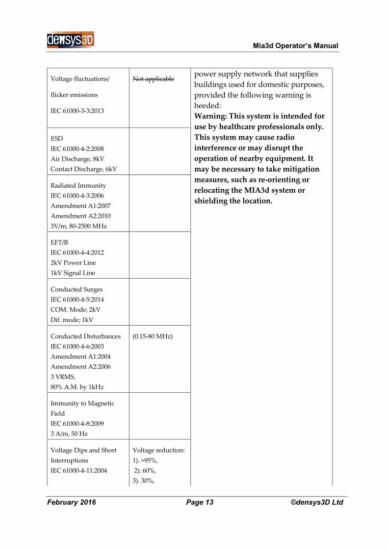
Voltage fluctuations/
flicker emissions
IEC 61000-3-3:2013
Not applicable power supply network that supplies
buildings used for domestic purposes,
provided the following warning is
heeded:
Warning: This system is intended for
use by healthcare professionals only.
This system may cause radio
interference or may disrupt the
operation of nearby equipment. It
may be necessary to take mitigation
measures, such as re-orienting or
relocating the MIA3d system or
shielding the location.
ESD
IEC 61000-4-2:2008
Air Discharge, 8kV
Contact Discharge, 6kV
Radiated Immunity
IEC 61000-4-3:2006
Amendment A1:2007
Amendment A2:2010
3V/m, 80-2500 MHz
EFT/B
IEC 61000-4-4:2012
2kV Power Line
1kV Signal Line
Conducted Surges
IEC 61000-4-5:2014
COM. Mode; 2kV
Dif. mode; 1kV
Conducted Disturbances
IEC 61000-4-6:2003
Amendment A1:2004
Amendment A2:2006
3 VRMS,
80% A.M. by 1kHz
(0.15-80 MHz)
Immunity to Magnetic
Field
IEC 61000-4-8:2009
3 A/m, 50 Hz
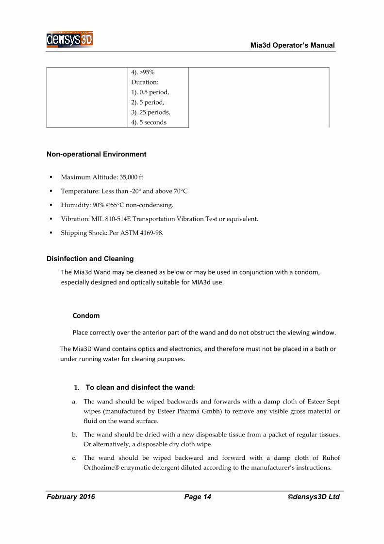
Voltage Dips and Short
Interruptions
IEC 61000-4-11:2004
Voltage reduction:
1). >95%,
2). 60%,
3). 30%,
Mia3d Operator’s Manual
February 2016 Page 14 ©densys3D Ltd
Non-operational Environment
Maximum Altitude: 35,000 ft
Temperature: Less than -20° and above 70°C
Humidity: 90% @55°C non-condensing.
Vibration: MIL 810-514E Transportation Vibration Test or equivalent.
Shipping Shock: Per ASTM 4169-98.
Disinfection and Cleaning
The Mia3d Wand may be cleaned as below or may be used in conjunction with a condom,
especially designed and optically suitable for MIA3d use.
Condom
Place correctly over the anterior part of the wand and do not obstruct the viewing window.
The Mia3D Wand contains optics and electronics, and therefore must not be placed in a bath or
under running water for cleaning purposes.
1. To clean and disinfect the wand:
a. The wand should be wiped backwards and forwards with a damp cloth of Esteer Sept
wipes (manufactured by Esteer Pharma Gmbh) to remove any visible gross material or
fluid on the wand surface.
b. The wand should be dried with a new disposable tissue from a packet of regular tissues.
Or alternatively, a disposable dry cloth wipe.
c. The wand should be wiped backward and forward with a damp cloth of Ruhof
Orthozime® enzymatic detergent diluted according to the manufacturer’s instructions.
4). >95%
Duration:
1). 0.5 period,
2). 5 period,
3). 25 periods,
4). 5 seconds
Mia3d Operator’s Manual
February 2016 Page 15 ©densys3D Ltd
d. The wand should be wiped with cloth duped with distilled water.
e. The wand should be placed on a clean table top or other horizontal surface and using
Propano AF spray (manufactured by Esteer Pharma Gmbh) sprayed evenly from a distance
of 30cm on all sides with the exception of the bottom side adjacent to the surface. It should
be left to dry for one minute.
f. The wand should be rotated and the steps listed above should be repeated to clean the side
of the wand adjacent to the horizontal surface.
NOTE: Please refer to Esteer Pharma Gmbh web site for cleaning material and wipes
information: http://www.esteer.com/
Please refer to Ruhof Corporation web site for cleaning detergent information:
http://www.ruhof.com/CatalogProducts.asp?nProductsID=82
2. To clean the viewing window:
a. Place some optic glass cleaning liquid on the wipe tissue provided.
b. Wipe the viewing window GENTLY in one direction only —do not rub back and forth
and do not scratch the viewing glass.
CAUTION: If you wipe vigorously you may scratch the viewing glass.
c. Dry the viewing window GENTLY with a dry wipe, wiping in one direction only.
3. When not in use, place the wand in its correct position on the wand stand.
WARNING: The handpiece is not delivered sterile, nor should it be sterile for use.
Implementation of the cleaning protocol before use, and in between patients,
is required for correct maintenance of the wand.
Biocompatibility
The handpiece is designed using materials which comply with EN 10993 standard.
The level of contact as stated in the standard: surface device in limited contact (<24 hours) with a
mucosal membrane.
Mia3d Operator’s Manual
February 2016 Page 16 ©densys3D Ltd
CAUTION
CAUTION: This section contains vital maintenance information that you must follow
to avoid damaging the equipment.
Densys3D hardware contains highly-refined optics and electronics. To avoid damaging this
equipment:
Do not drop or bang the wand.
Avoid contact of the wand with any materials or solutions other than those authorized in the user
manual.
Do not immerse the handpiece in solutions or baths.
Do not place the wand under a running tap.
Do not place the wand in an autoclave or a dry heat sterilizer.
Do not wet the wand, or any part of the Densys3D system, other than in a manner or with a
material authorized for use in the user manual.
Mia3d Operator’s Manual
February 2016 Page 17 ©densys3D Ltd
Installation
CAUTION: Unpacking and installation of the Mia3d system must only be performed
by a qualified Densys3D technician.
Unpacking and Inspection
Unpack each Mia3d system component and inspect for physical damage such as scratched panels
or damaged connectors, etc. If any damage is noted, immediately notify the supplier so that the
damaged components can be replaced.
Make sure to save all packaging material in case repackaging and shipment is necessary. Verify
that all listed items were received.
If any item is missing, notify the supplier. Each Mia3d system component is shipped packaged in
an individual protective container, or packed in a single box.
The laptop is supplied in its own box from the laptop manufacturer.
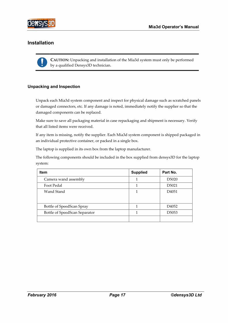
The following components should be included in the box supplied from densys3D for the laptop
system:
Item Supplied Part No.
Camera wand assembly 1 D5020
Foot Pedal 1 D5021
Wand Stand 1 D4051
Bottle of SpeedScan Spray 1 D4052
Bottle of SpeedScan Separator 1 D5053
Mia3d Operator’s Manual
February 2016 Page 18 ©densys3D Ltd
Mia3D Operating Instructions
Mia3d operates on a Windows 10 Operation System.
The following instructions lead you through all the Mia3d wizard pages.
CAUTION: Place the wand when not in use face down on the stand
NOTE: The actual implementation of the scan takes less than 60 seconds.
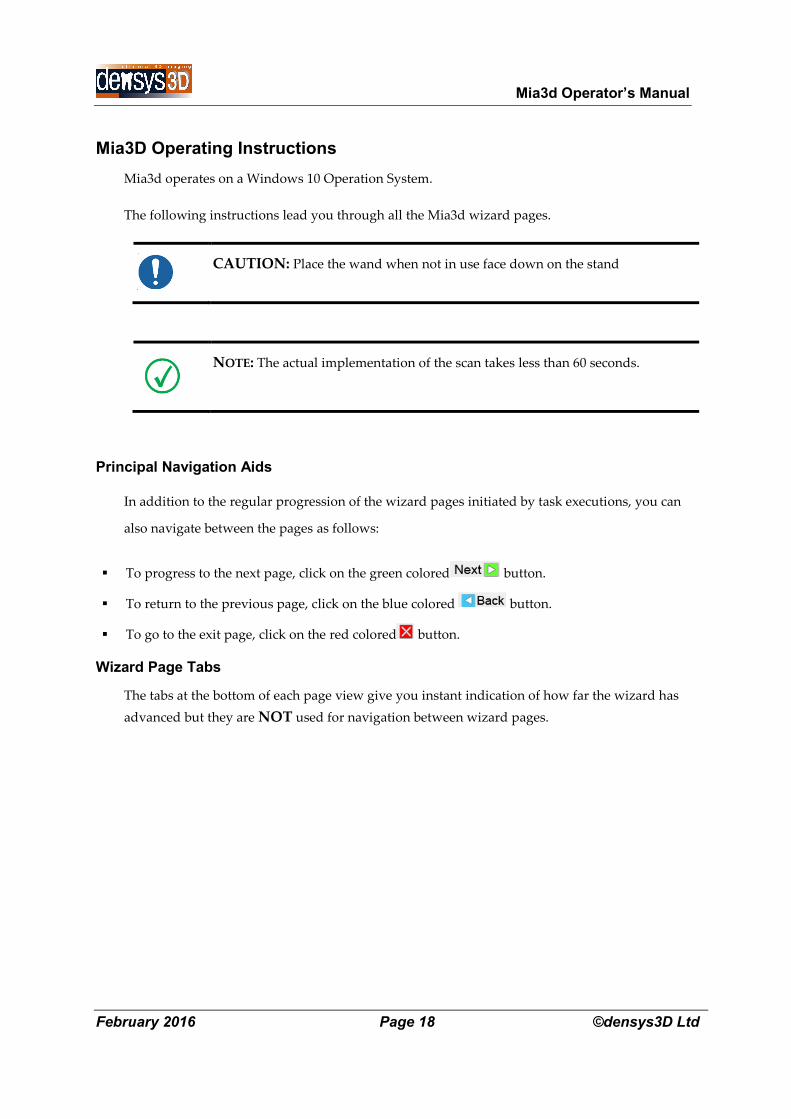
Principal Navigation Aids
In addition to the regular progression of the wizard pages initiated by task executions, you can
also navigate between the pages as follows:
To progress to the next page, click on the green colored button.
To return to the previous page, click on the blue colored button.
To go to the exit page, click on the red colored button.
Wizard Page Tabs
The tabs at the bottom of each page view give you instant indication of how far the wizard has
advanced but they are NOT used for navigation between wizard pages.
Mia3d Operator’s Manual
February 2016 Page 19 ©densys3D Ltd
Pre-Scan setup
CAUTION: Before starting a dental scan it is essential to implement the steps described in
Pre-Scan setup.
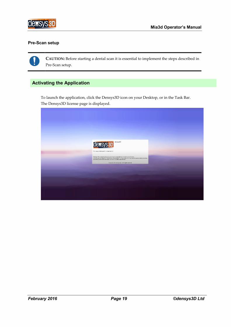
Activating the Application
To launch the application, click the Densys3D icon on your Desktop, or in the Task Bar.
The Densys3D license page is displayed.
Mia3d Operator’s Manual
February 2016 Page 20 ©densys3D Ltd
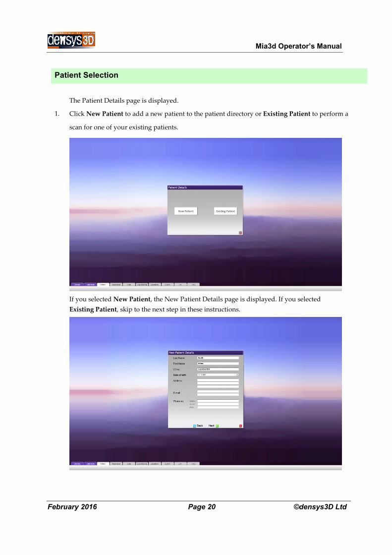
Patient Selection
1.
The Patient Details page is displayed.
Click New Patient to add a new patient to the patient directory or Existing Patient to perform a
scan for one of your existing patients.
If you selected New Patient, the New Patient Details page is displayed. If you selected
Existing Patient, skip to the next step in these instructions.
Mia3d Operator’s Manual
February 2016 Page 21 ©densys3D Ltd
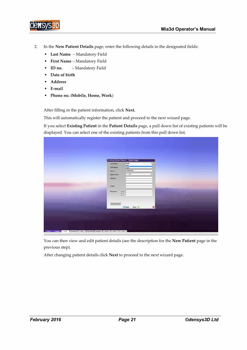
2. In the New Patient Details page, enter the following details in the designated fields:
Last Name – Mandatory Field
First Name – Mandatory Field
ID no. – Mandatory Field
Date of birth
Address
Phone no. (Mobile, Home, Work)
After filling in the patient information, click Next.
This will automatically register the patient and proceed to the next wizard page.
If you select Existing Patient in the Patient Details page, a pull down list of existing patients will be
displayed. You can select one of the existing patients from this pull down list.
You can then view and edit patient details (see the description for the New Patient page in the
previous step).
After changing patient details click Next to proceed to the next wizard page.
Mia3d Operator’s Manual
February 2016 Page 22 ©densys3D Ltd
Restoration
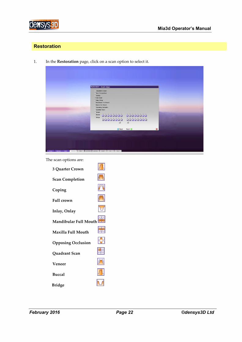
1.
In the Restoration page, click on a scan option to select it.
The scan options are:
3 Quarter Crown
Scan Completion
Coping
Full crown
Inlay, Onlay
Mandibular Full Mouth
Maxilla Full Mouth
Opposing Occlusion
Quadrant Scan
Veneer
Buccal
Bridge
Mia3d Operator’s Manual
February 2016 Page 23 ©densys3D Ltd
2.
If you select the Bridge option, the Abutment or Pontic indicators are activated.
Click on each of the numbered teeth you want to include in the scan:
The selected tooth displays the icon for the treatment chosen.
You can undo your tooth selection by clicking again.
3. Click Next to save the scan setup and to continue to the next step.
Clinical Pre-Scan Setup
1.
Setup the wand:
Ensure that the wand is cleaned and disinfected to prevent cross infection before use as
specified in the Disinfection section.
Check that the viewing window is clean and dirt free. If it is dirty preform the cleaning
procedure detailed in the Disinfection section.
Mia3d Operator’s Manual
February 2016 Page 24 ©densys3D Ltd
2.
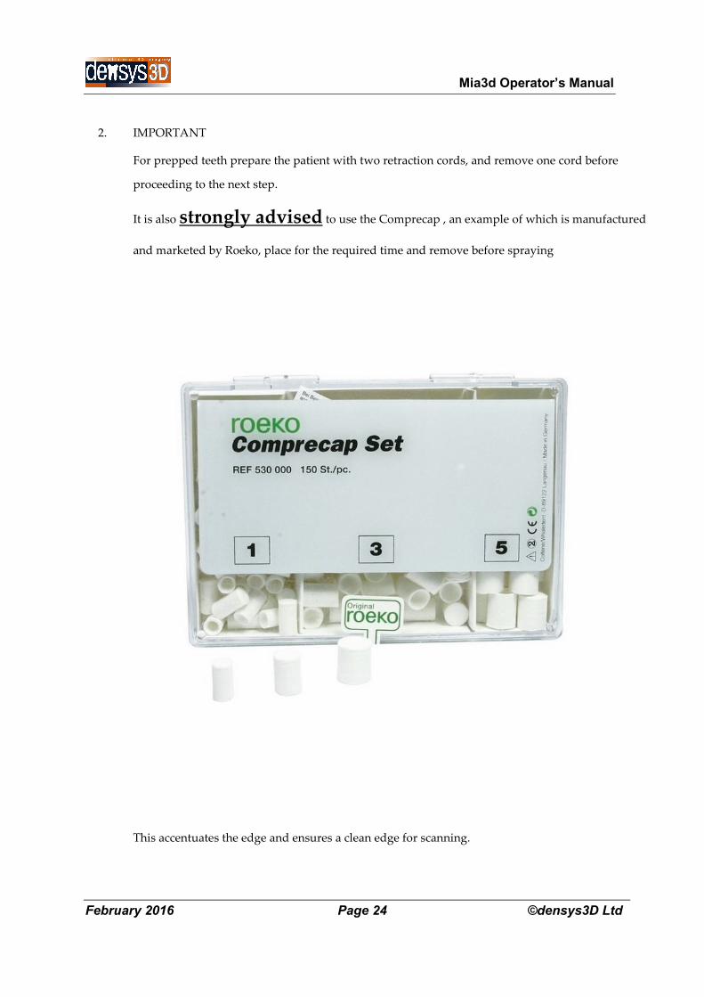
IMPORTANT
For prepped teeth prepare the patient with two retraction cords, and remove one cord before
proceeding to the next step.
It is also strongly advised to use the Comprecap , an example of which is manufactured
and marketed by Roeko, place for the required time and remove before spraying
This accentuates the edge and ensures a clean edge for scanning.
Mia3d Operator’s Manual
February 2016 Page 25 ©densys3D Ltd
Make certain there is no bleeding in the area of the intra oral impression
3. Apply the spray
Shake the spray can vigorously
Attach nozzle to spray can.
If the nozzle has a white residue from a previous use, clean the residue from the nozzle
Clean, dry well with a prolonged air flow from the syringe and isolate the teeth and any non-
movable soft tissue around the teeth from any fluid present in the oral cavity.
Hold spray approximately 8mm from teeth.
Apply spray evenly to the teeth and the adjacent gingivae by moving nozzle over the areas that
are to be scanned.
Don’t forget to spray any non-movable soft tissue in the scan area.
DO NOT spray movable soft tissue. This will cause an inaccurate scan.
If you have sprayed the moveable soft tissue WIPE THE SPRAY OFF the tissue before it dries
Wait for spray to dry while holding the movable soft tissue, away from the other tissues.
If at any time during the procedure you need to respray, first dry the existing surfaces with the
air syringe
NOTE: Keeping the sprayed tooth dry is essential to achieving a quality scan. Any wetting of
the powder will result reduce scan accuracy.
Mia3d Operator’s Manual
February 2016 Page 26 ©densys3D Ltd
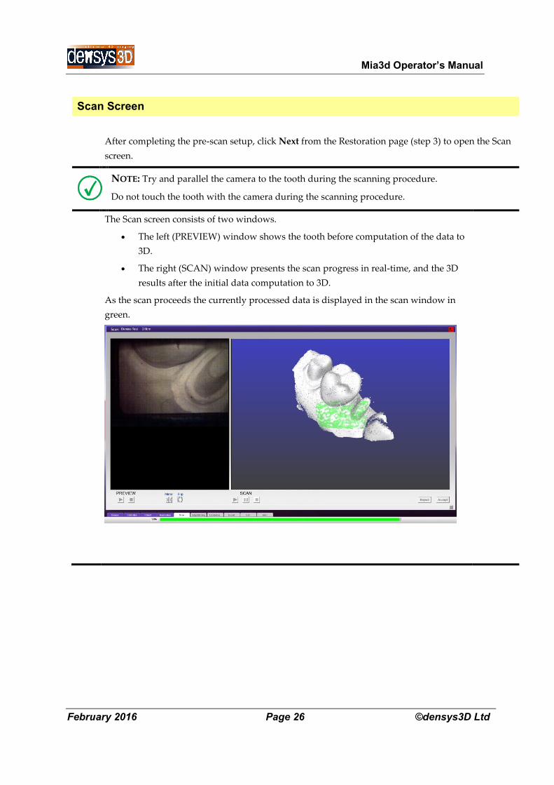
Scan Screen
After completing the pre-scan setup, click Next from the Restoration page (step 3) to open the Scan
screen.
NOTE: Try and parallel the camera to the tooth during the scanning procedure.
Do not touch the tooth with the camera during the scanning procedure.
The Scan screen consists of two windows.
The left (PREVIEW) window shows the tooth before computation of the data to
3D.
The right (SCAN) window presents the scan progress in real-time, and the 3D
results after the initial data computation to 3D.
As the scan proceeds the currently processed data is displayed in the scan window in
green.

Mia3d Operator’s Manual
February 2016 Page 27 ©densys3D Ltd
NOTE: The scanning method described in the following steps is a suggested, recommended
method. Some users may prefer to follow a different method. A new user is advised to practice
his scanning technique in the preview window before activating the scan.
Mia3d Operator’s Manual
February 2016 Page 28 ©densys3D Ltd
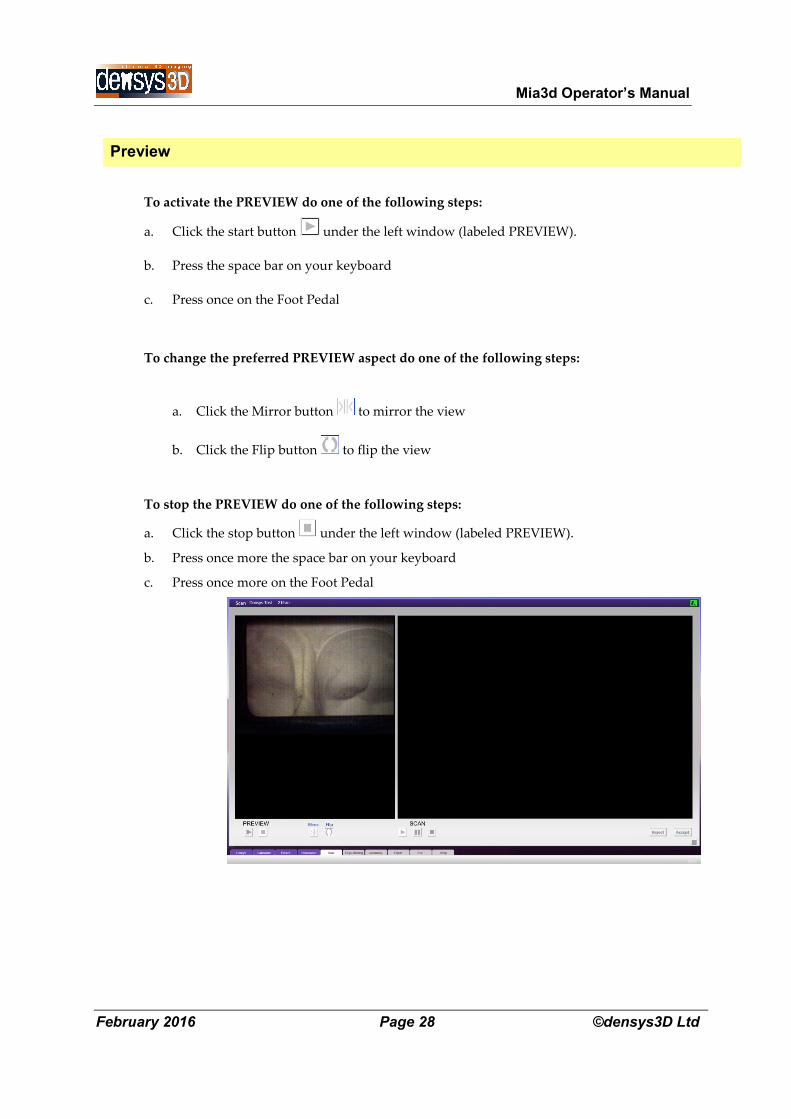
Preview
To activate the PREVIEW do one of the following steps:
a. Click the start button under the left window (labeled PREVIEW).
b. Press the space bar on your keyboard
c. Press once on the Foot Pedal
To change the preferred PREVIEW aspect do one of the following steps:
a. Click the Mirror button to mirror the view
b. Click the Flip button to flip the view
To stop the PREVIEW do one of the following steps:
a. Click the stop button under the left window (labeled PREVIEW).
b. Press once more the space bar on your keyboard
c. Press once more on the Foot Pedal
Mia3d Operator’s Manual
February 2016 Page 29 ©densys3D Ltd
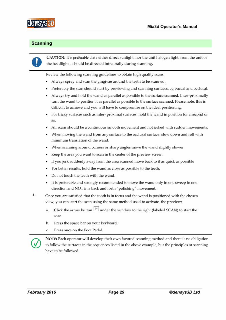
Scanning
CAUTION: It is preferable that neither direct sunlight, nor the unit halogen light, from the unit or
the headlight , should be directed intra orally during scanning.
Review the following scanning guidelines to obtain high quality scans.
Always spray and scan the gingivae around the teeth to be scanned,
Preferably the scan should start by previewing and scanning surfaces, eg buccal and occlusal.
Always try and hold the wand as parallel as possible to the surface scanned. Inter-proximally
turn the wand to position it as parallel as possible to the surface scanned. Please note, this is
difficult to achieve and you will have to compromise on the ideal positioning.
For tricky surfaces such as inter- proximal surfaces, hold the wand in position for a second or
so.
All scans should be a continuous smooth movement and not jerked with sudden movements.
When moving the wand from any surface to the occlusal surface, slow down and roll with
minimum translation of the wand.
When scanning around corners or sharp angles move the wand slightly slower.
Keep the area you want to scan in the center of the preview screen.
If you jerk suddenly away from the area scanned move back to it as quick as possible
For better results, hold the wand as close as possible to the teeth.
Do not touch the teeth with the wand.
It is preferable and strongly recommended to move the wand only in one sweep in one
direction and NOT in a back and forth “polishing” movement.
1. Once you are satisfied that the tooth is in focus and the wand is positioned with the chosen
view, you can start the scan using the same method used to activate the preview:
a. Click the arrow button under the window to the right (labeled SCAN) to start the
scan.
b. Press the space bar on your keyboard.
c. Press once on the Foot Pedal.
NOTE: Each operator will develop their own favored scanning method and there is no obligation
to follow the surfaces in the sequences listed in the above example, but the principles of scanning
have to be followed.

Mia3d Operator’s Manual
February 2016 Page 30 ©densys3D Ltd
2. As you move the wand a real time scan appears in the SCAN window. It covers the same area that
is shown in the PREVIEW window to the left.
The wand should be moved in fluid movement adjusted to the comfort of the user, and the clinical
situation. The scanner works by automatically adjoining adjacent areas, and if the user jerks the
scanner out of place, or views only a very small area, or views moveable soft tissue, then this can lead
to a critical situation as below.
The following is a help to describe the scan status for the dentist
A. Colored data input
B. AUDIO - Sounds accompanying the scan
A. Colored Data Input
The colored dots appearing on the scan screen show the latest data coming into the scan in real-time.
Green dots - on the right scan window is good data and is accompanied by a regular spaced
short beep when scanning
Yellow dots – when the data coming in is yellow (accompanied by mixed short and high tone
beeps when scanning) the operator should relate to one of the following potential problems
about to happen and unless corrected there will be a view with Pink dots –
Pink dots - this indicated the situation is critical and unless the operator corrects as below as
in Section 3 he will have an incomplete scan
B. AUDIO – Sounds accompanying the scan
There are audio sounds accompanying the scan that demonstrate the different colored
screens. This helps the user
Green data - regular spaced short beep.
Yellow data – regular long beep
Pink data – no beep
Mia3d Operator’s Manual
February 2016 Page 31 ©densys3D Ltd
3. In case of getting to critical situation (pink dots and warning high beep) the scan will stop
temporarily.
There are then three possible options
A. To use the PAUSE/ INSTANT RESTART method
B. To reposition at the place of the last good scan. (more difficult)
C. Combination of reposition and PAUSE/INSTANT RESTART (recommended)
We recommend the use of the automatic reposition and if the user does not succeed within a few
seconds that the user activate ( with a press on the foot pedal as below ) , the PAUSE / INSTANT
RESTART
PAUSE / INSTANT RESTART
This function is most commonly used after pink dot critical situation, but can also be used at any
other time.
The user may for a second or two try to reposition the scanner after critical situation
At any time user can pause the scan to unlimited period of time by pressing on foot pedal, space
button or clicking with mouse on . User may resume the scan process by pressing on foot pedal,
space button or clicking with mouse on or to stop the scan completely by double pressing on foot
pedal, space button or clicking with mouse on . Resuming after pause may start from almost any
area previously scanned, although it is best to return to a previous good location with a large view of
the teeth or soft tissue that was previously scanned, For example, 1-2 teeth or even half jaw before the
pause area.
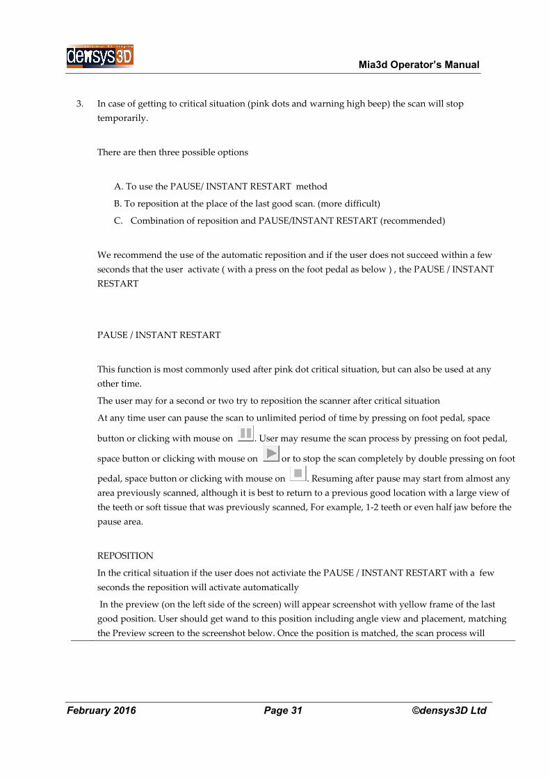
REPOSITION
In the critical situation if the user does not activiate the PAUSE / INSTANT RESTART with a few
seconds the reposition will activate automatically
In the preview (on the left side of the screen) will appear screenshot with yellow frame of the last
good position. User should get wand to this position including angle view and placement, matching
the Preview screen to the screenshot below. Once the position is matched, the scan process will
Mia3d Operator’s Manual
February 2016 Page 32 ©densys3D Ltd
continue as usual.
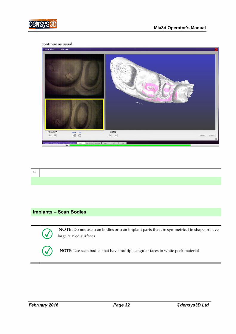
4.
Implants – Scan Bodies
NOTE: Do not use scan bodies or scan implant parts that are symmetrical in shape or have
large curved surfaces
NOTE: Use scan bodies that have multiple angular faces in white peek material
Mia3d Operator’s Manual
February 2016 Page 33 ©densys3D Ltd
Scan bodies that are appropriate include:
A. Densys Scan Body
B. Straumann Scan Body type
C. Sirona Scan Body
Densys cannot guarantee a successful scan with other implant parts or scan bodies.
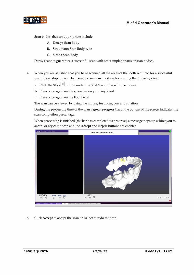
4. When you are satisfied that you have scanned all the areas of the tooth required for a successful
restoration, stop the scan by using the same methods as for starting the preview/scan:
a. Click the Stop button under the SCAN window with the mouse
b. Press once again on the space bar on your keyboard
c. Press once again on the Foot Pedal
The scan can be viewed by using the mouse, for zoom, pan and rotation.
During the processing time of the scan a green progress bar at the bottom of the screen indicates the
scan completion percentage.
When processing is finished (the bar has completed its progress) a message pops up asking you to
accept or reject the scan and the Accept and Reject buttons are enabled.
5.
Click Accept to accept the scan or Reject to redo the scan.
Mia3d Operator’s Manual
February 2016 Page 34 ©densys3D Ltd
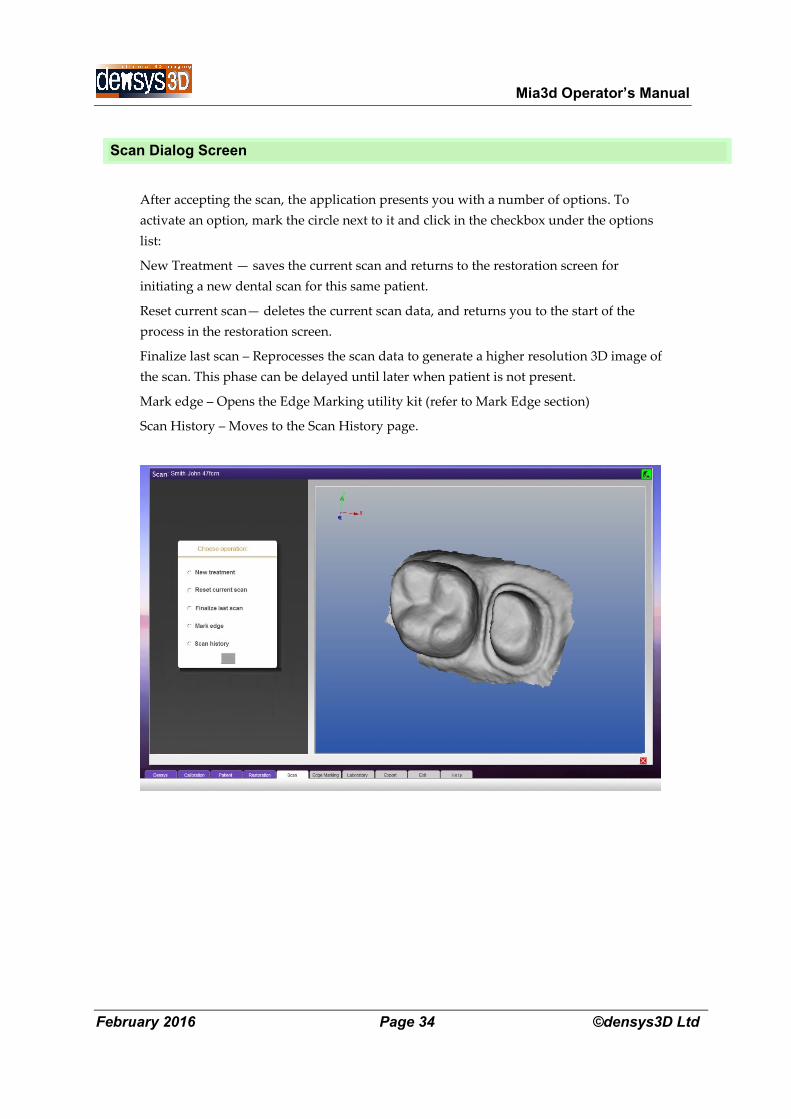
Scan Dialog Screen
After accepting the scan, the application presents you with a number of options. To
activate an option, mark the circle next to it and click in the checkbox under the options
list:
New Treatment — saves the current scan and returns to the restoration screen for
initiating a new dental scan for this same patient.
Reset current scan— deletes the current scan data, and returns you to the start of the
process in the restoration screen.
Finalize last scan – Reprocesses the scan data to generate a higher resolution 3D image of
the scan. This phase can be delayed until later when patient is not present.
Mark edge – Opens the Edge Marking utility kit (refer to Mark Edge section)
Scan History – Moves to the Scan History page.
Mia3d Operator’s Manual
February 2016 Page 35 ©densys3D Ltd
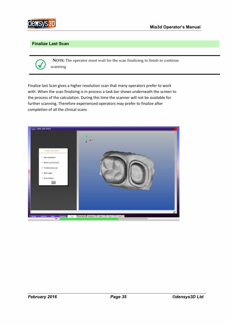
Finalize Last Scan
NOTE: The operator must wait for the scan finalizing to finish to continue
scanning
Finalize last Scan gives a higher resolution scan that many operators prefer to work
with. When the scan finalizing is in process a task bar shows underneath the screen to
the process of the calculation. During this time the scanner will not be available for
further scanning. Therefore experienced operators may prefer to finalize after
completion of all the clinical scans
Mia3d Operator’s Manual
February 2016 Page 36 ©densys3D Ltd
Edge Marking
NOTE: Edge marking is essential in restorative virtual impressions to enable an accurate and
clearly defined margin for prosthetic manufacture.
Edge marking is required for all scans of prepared teeth for prosthetic restoration
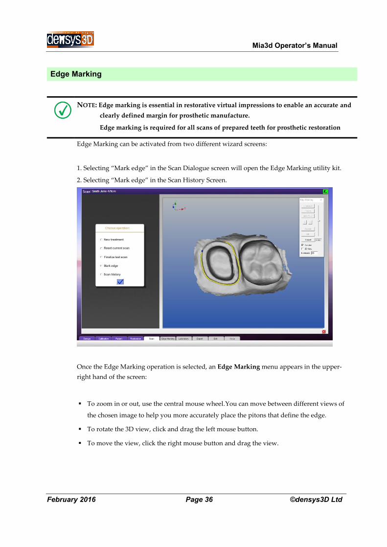
Edge Marking can be activated from two different wizard screens:
1. Selecting “Mark edge” in the Scan Dialogue screen will open the Edge Marking utility kit.
2. Selecting “Mark edge” in the Scan History Screen.
Once the Edge Marking operation is selected, an Edge Marking menu appears in the upper-
right hand of the screen:
To zoom in or out, use the central mouse wheel.You can move between different views of
the chosen image to help you more accurately place the pitons that define the edge.
To rotate the 3D view, click and drag the left mouse button.
To move the view, click the right mouse button and drag the view.
Mia3d Operator’s Manual
February 2016 Page 37 ©densys3D Ltd
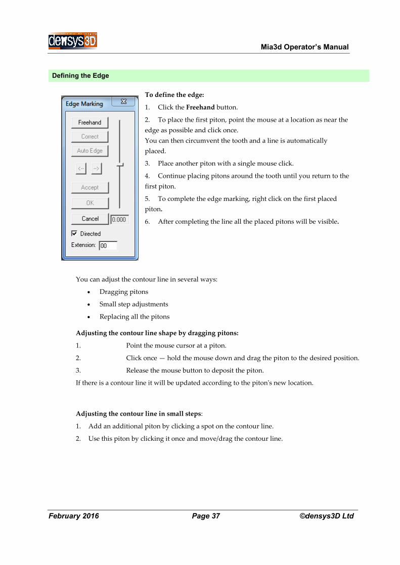
Defining the Edge
To define the edge:
1. Click the Freehand button.
2. To place the first piton, point the mouse at a location as near the
edge as possible and click once.
You can then circumvent the tooth and a line is automatically
placed.
3. Place another piton with a single mouse click.
4. Continue placing pitons around the tooth until you return to the
first piton.
5. To complete the edge marking, right click on the first placed
piton.
6. After completing the line all the placed pitons will be visible.
You can adjust the contour line in several ways:
Dragging pitons
Small step adjustments
Replacing all the pitons
Adjusting the contour line shape by dragging pitons:
1. Point the mouse cursor at a piton.
2. Click once — hold the mouse down and drag the piton to the desired position.
3. Release the mouse button to deposit the piton.
If there is a contour line it will be updated according to the piton's new location.
Adjusting the contour line in small steps:
1. Add an additional piton by clicking a spot on the contour line.
2. Use this piton by clicking it once and move/drag the contour line.
Mia3d Operator’s Manual
February 2016 Page 38 ©densys3D Ltd
Correcting the contour line by replacing the pitons:
1. Click the Correct button.
All the pitons on the contour line will disappear.
2. Place a minimum of three pitons with two of them positioned on the existing contour line.
3. Make a right-mouse click and the new line and contour will replace the old line between the
pitons you added.
Deleting Pitons
To delete a single piton point, place the mouse cursor on it and press Delete on the Keyboard.
To delete all pitons, click the Cancel button in the menu in the upper right corner of the
screen (see the above illustration). – Note: This will also remove the contour line between the
pitons.
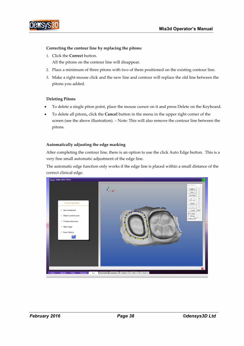
Automatically adjusting the edge marking
After completing the contour line, there is an option to use the click Auto Edge button. This is a
very fine small automatic adjustment of the edge line.
The automatic edge function only works if the edge line is placed within a small distance of the
correct clinical edge.
Mia3d Operator’s Manual
February 2016 Page 39 ©densys3D Ltd
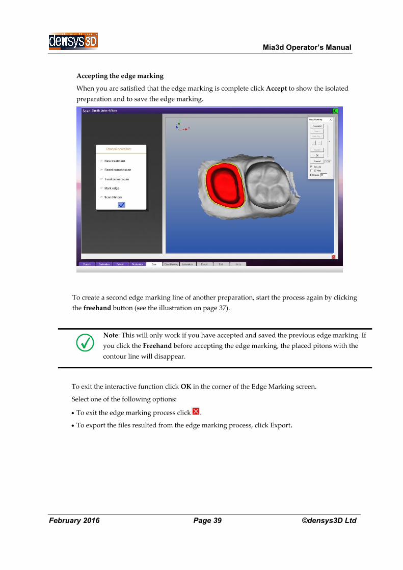
Accepting the edge marking
When you are satisfied that the edge marking is complete click Accept to show the isolated
preparation and to save the edge marking.
To create a second edge marking line of another preparation, start the process again by clicking
the freehand button (see the illustration on page 37).
Note: This will only work if you have accepted and saved the previous edge marking. If
you click the Freehand before accepting the edge marking, the placed pitons with the
contour line will disappear.
To exit the interactive function click OK in the corner of the Edge Marking screen.
Select one of the following options:
To exit the edge marking process click .
To export the files resulted from the edge marking process, click Export.
Mia3d Operator’s Manual
February 2016 Page 40 ©densys3D Ltd
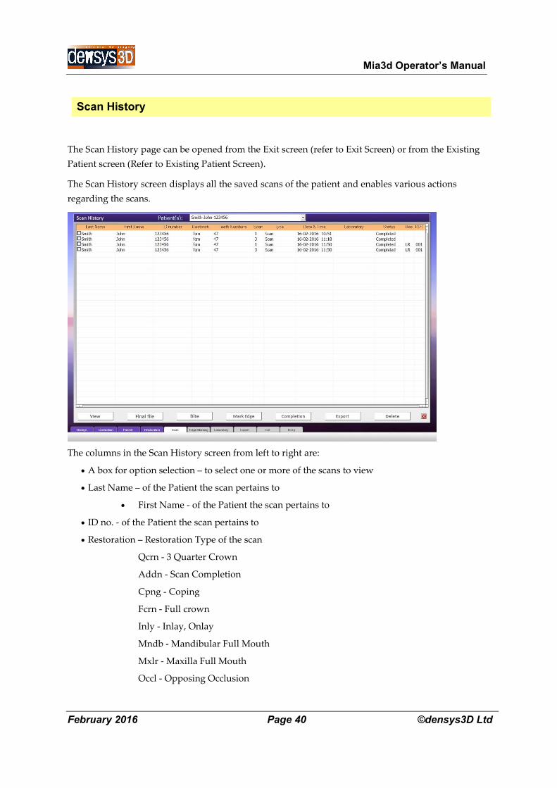
Scan History
The Scan History page can be opened from the Exit screen (refer to Exit Screen) or from the Existing
Patient screen (Refer to Existing Patient Screen).
The Scan History screen displays all the saved scans of the patient and enables various actions
regarding the scans.
The columns in the Scan History screen from left to right are:
A box for option selection – to select one or more of the scans to view
Last Name – of the Patient the scan pertains to
First Name - of the Patient the scan pertains to
ID no. - of the Patient the scan pertains to
Restoration – Restoration Type of the scan
Qcrn - 3 Quarter Crown
Addn - Scan Completion
Cpng - Coping
Fcrn - Full crown
Inly - Inlay, Onlay
Mndb - Mandibular Full Mouth
Mxlr - Maxilla Full Mouth
Occl - Opposing Occlusion
Mia3d Operator’s Manual
February 2016 Page 41 ©densys3D Ltd
Qdrt - Quadrant Scan
Vner - Veneer
Bccl - Buccal
Pntc - Bridge
Teeth numbers – Which teeth were selected for the scan
Scan – Number of scans performed on the same set of defined teeth
Type – Scan Type
Date and Time – Date and time the scan was taken.
Laboratory – What Laboratory the scan has been exported to
Status – displays the scan status (Completed / Not Completed)
Res – Displays HR if the scan is in high resolution
RPT – Number of times this scan has been finalized
Click on one of the action buttons in the lower portion of the screen to activate a function according to
the different sections in this User Manual.
The different buttons are:
View – Can view up to 8 different scans (refer to View)
HR File – Reprocesses the scan data to generate a higher resolution 3D image of the scan. When using
this function the scanner cannot be used WARNING. This phase can be delayed until later when
patient is not present.
Bite – Prompt you to the Bite Screen. (Refer to Bite)
Mark Edge – Opens the scan with the edge marking utility. Can only open one scan for edge marking.
(Refer to Edge Marking)
Completion – Opens the Scan Completion screen. Only choose 2 scans. (refer to Scan Completion)
Export – Prompts you to the Laboratory Screen to choose a laboratory to export the selected scans to.
(Refer to Export)
Delete – Deletes any selected scans
Mia3d Operator’s Manual
February 2016 Page 42 ©densys3D Ltd
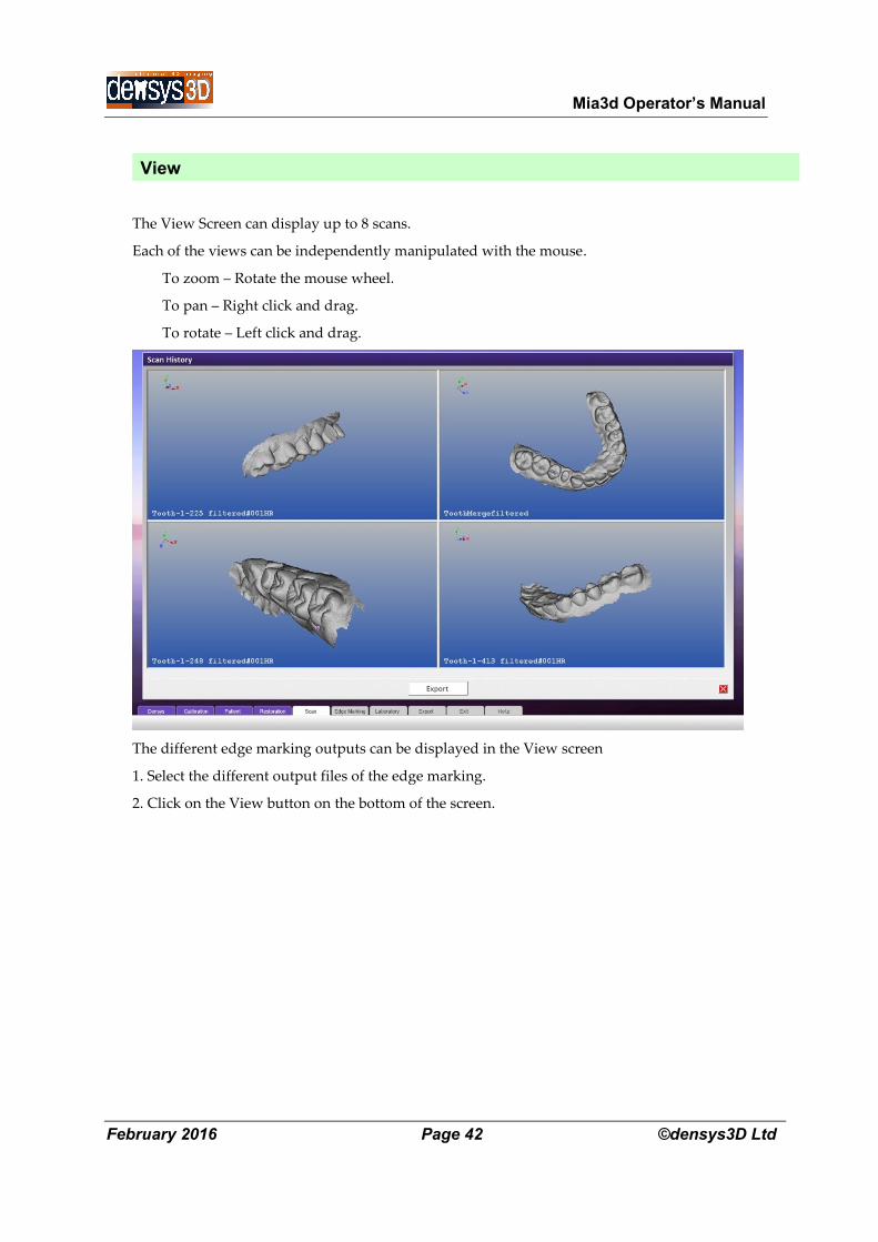
View
The View Screen can display up to 8 scans.
Each of the views can be independently manipulated with the mouse.
To zoom – Rotate the mouse wheel.
To pan – Right click and drag.
To rotate – Left click and drag.
The different edge marking outputs can be displayed in the View screen
1. Select the different output files of the edge marking.
2. Click on the View button on the bottom of the screen.
Mia3d Operator’s Manual
February 2016 Page 43 ©densys3D Ltd
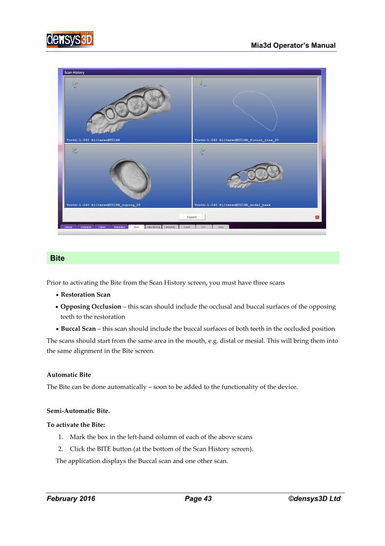
Bite
Prior to activating the Bite from the Scan History screen, you must have three scans
Restoration Scan
Opposing Occlusion – this scan should include the occlusal and buccal surfaces of the opposing
teeth to the restoration
Buccal Scan – this scan should include the buccal surfaces of both teeth in the occluded position
The scans should start from the same area in the mouth, e.g. distal or mesial. This will bring them into
the same alignment in the Bite screen.
Automatic Bite
The Bite can be done automatically – soon to be added to the functionality of the device.
Semi-Automatic Bite.
To activate the Bite:
1. Mark the box in the left-hand column of each of the above scans
2. Click the BITE button (at the bottom of the Scan History screen).
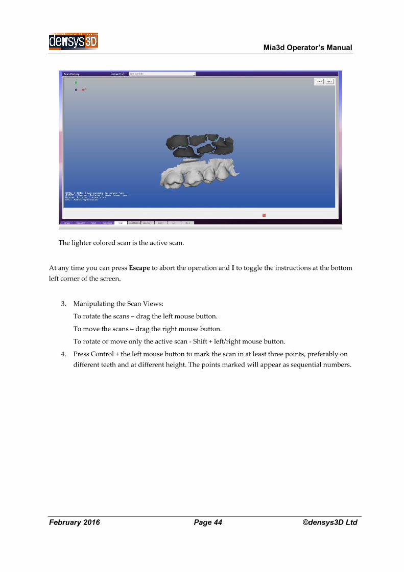
The application displays the Buccal scan and one other scan.
Mia3d Operator’s Manual
February 2016 Page 44 ©densys3D Ltd
The lighter colored scan is the active scan.
At any time you can press Escape to abort the operation and I to toggle the instructions at the bottom
left corner of the screen.
3. Manipulating the Scan Views:
To rotate the scans – drag the left mouse button.
To move the scans – drag the right mouse button.
To rotate or move only the active scan - Shift + left/right mouse button.
4. Press Control + the left mouse button to mark the scan in at least three points, preferably on
different teeth and at different height. The points marked will appear as sequential numbers.
Mia3d Operator’s Manual
February 2016 Page 45 ©densys3D Ltd
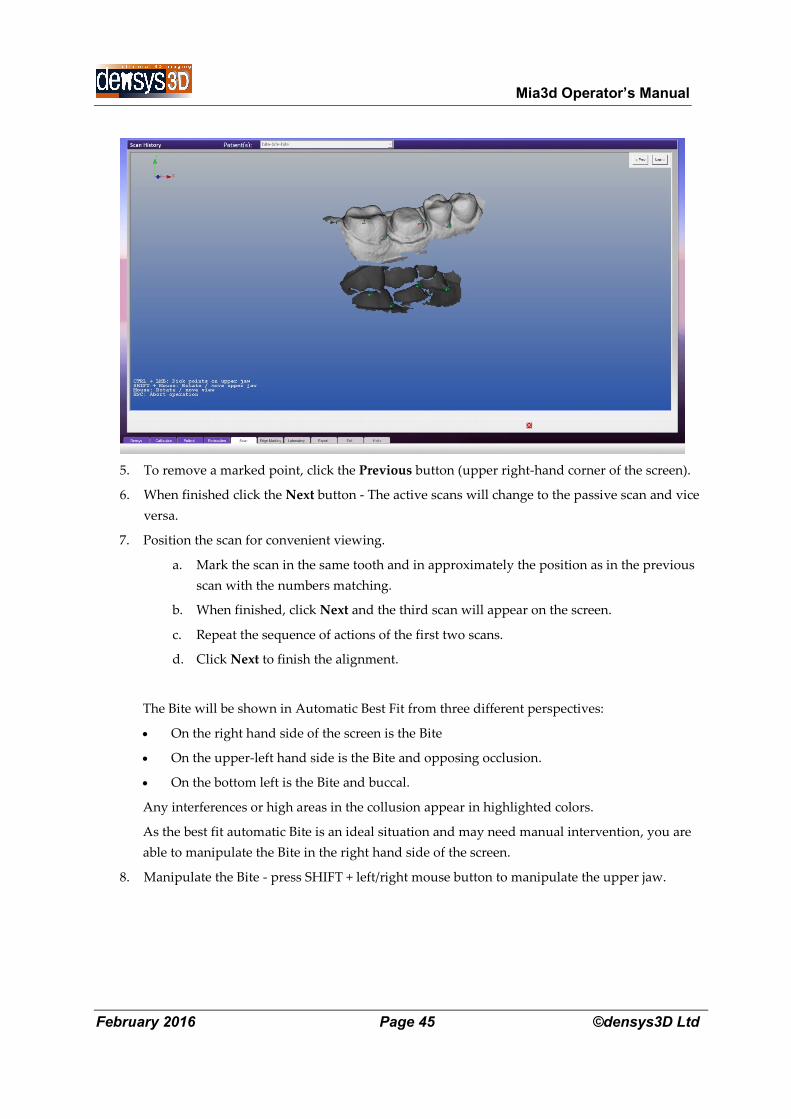
5. To remove a marked point, click the Previous button (upper right-hand corner of the screen).
6. When finished click the Next button - The active scans will change to the passive scan and vice
versa.
7. Position the scan for convenient viewing.
a. Mark the scan in the same tooth and in approximately the position as in the previous
scan with the numbers matching.
b. When finished, click Next and the third scan will appear on the screen.
c. Repeat the sequence of actions of the first two scans.
d. Click Next to finish the alignment.
The Bite will be shown in Automatic Best Fit from three different perspectives:
On the right hand side of the screen is the Bite
On the upper-left hand side is the Bite and opposing occlusion.
On the bottom left is the Bite and buccal.
Any interferences or high areas in the collusion appear in highlighted colors.
As the best fit automatic Bite is an ideal situation and may need manual intervention, you are
able to manipulate the Bite in the right hand side of the screen.
8. Manipulate the Bite - press SHIFT + left/right mouse button to manipulate the upper jaw.
Mia3d Operator’s Manual
February 2016 Page 46 ©densys3D Ltd
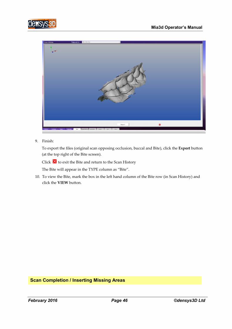
9. Finish:
To export the files (original scan opposing occlusion, buccal and Bite), click the Export button
(at the top right of the Bite screen).
Click to exit the Bite and return to the Scan History
The Bite will appear in the TYPE column as “Bite”.
10. To view the Bite, mark the box in the left hand column of the Bite row (in Scan History) and
click the VIEW button.
Scan Completion / Inserting Missing Areas
Mia3d Operator’s Manual
February 2016 Page 47 ©densys3D Ltd
Scan completion can be used to add in missing areas or to join adjacent areas, e.g. sextants or
quadrants.
Scan completion can be done in two circumstances,
A. During a scan
B. After a scan is finished
During a scan
It is always best when adding missing areas or doing completion to add in substantial areas from the
teeth adjacent to the areas scanned, for example a tooth on each side.
Place the scanner view on the area already scanned near the missing area, and then use Pause / Instant
Restart
During the scan go back to the missing area as in Section 3 page XX above, using Pause instant restart
till the missing area is filled in.
Remember it is best to minimally rescan an existing scanned surface, and brushing back and forwards
movements should NOT be used.
After a scan is finished
If after a scan is finished the user wants to add new material scanned , the user should use the
COMPLETION function
Scan completion is semi – automatic, and will soon also be released in a fully automatic version.
NOTE: For all cases there should be an overlap of at least one tooth on the areas to be
matched.
Scan Completion can be activated from the Scan History screen.
1.
SCAN CIOMPLETION from the Scan History screen
1. In the Scan History screen, mark two scans in the left hand column.
2. Click the COMPLETE button (at the bottom of the screen)
You will now be prompted to the Scan Completion screen
Mia3d Operator’s Manual
February 2016 Page 48 ©densys3D Ltd
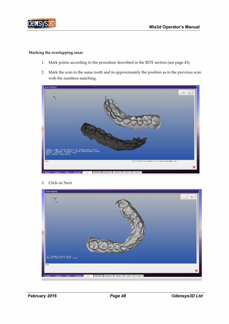
Marking the overlapping areas
1. Mark points according to the procedure described in the BITE section (see page 43).
2. Mark the scan in the same tooth and in approximately the position as in the previous scan
with the numbers matching.
3. Click on Next.
Mia3d Operator’s Manual
February 2016 Page 49 ©densys3D Ltd
4. Click on Export to export the scan to a laboratory or click on the to return to the Scan
History screen.
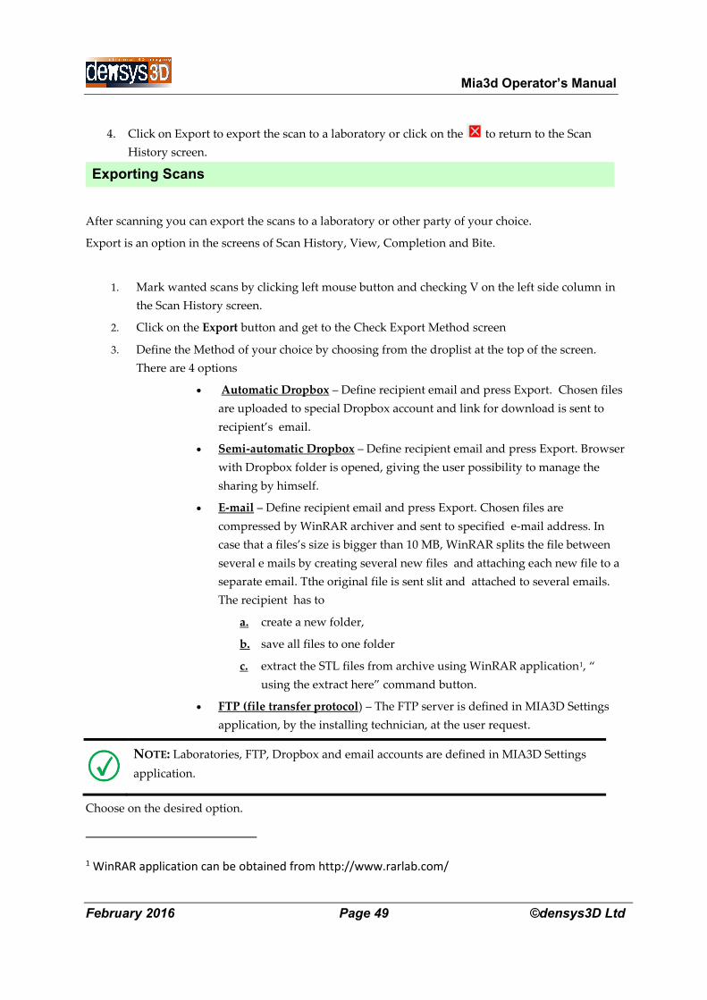
Exporting Scans
After scanning you can export the scans to a laboratory or other party of your choice.
Export is an option in the screens of Scan History, View, Completion and Bite.
1. Mark wanted scans by clicking left mouse button and checking V on the left side column in
the Scan History screen.
2. Click on the Export button and get to the Check Export Method screen
3. Define the Method of your choice by choosing from the droplist at the top of the screen.
There are 4 options
Automatic Dropbox – Define recipient email and press Export. Chosen files
are uploaded to special Dropbox account and link for download is sent to
recipient’s email.
Semi-automatic Dropbox – Define recipient email and press Export. Browser
with Dropbox folder is opened, giving the user possibility to manage the
sharing by himself.
E-mail – Define recipient email and press Export. Chosen files are
compressed by WinRAR archiver and sent to specified e-mail address. In
case that a files’s size is bigger than 10 MB, WinRAR splits the file between
several e mails by creating several new files and attaching each new file to a
separate email. Tthe original file is sent slit and attached to several emails.
The recipient has to
a. create a new folder,
b. save all files to one folder
c. extract the STL files from archive using WinRAR application1, “
using the extract here” command button.
FTP (file transfer protocol) – The FTP server is defined in MIA3D Settings
application, by the installing technician, at the user request.
NOTE: Laboratories, FTP, Dropbox and email accounts are defined in MIA3D Settings
application.
Choose on the desired option.
1 WinRAR application can be obtained from http://www.rarlab.com/
Mia3d Operator’s Manual
February 2016 Page 50 ©densys3D Ltd
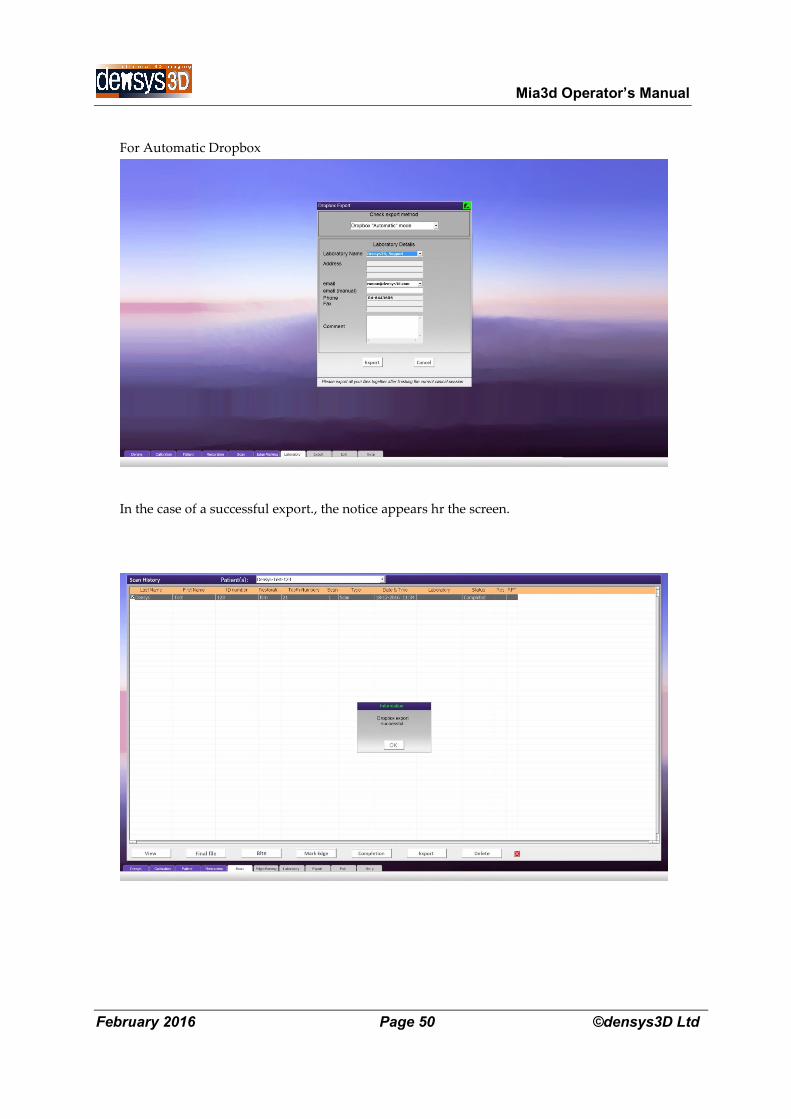
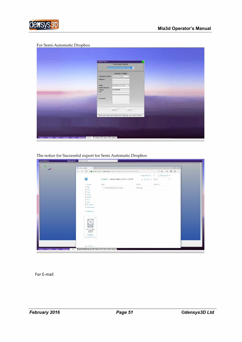
For Automatic Dropbox
In the case of a successful export., the notice appears hr the screen.
Mia3d Operator’s Manual
February 2016 Page 51 ©densys3D Ltd
For Semi-Automatic Dropbox
The notice for Successful export for Semi Automatic Dropbox
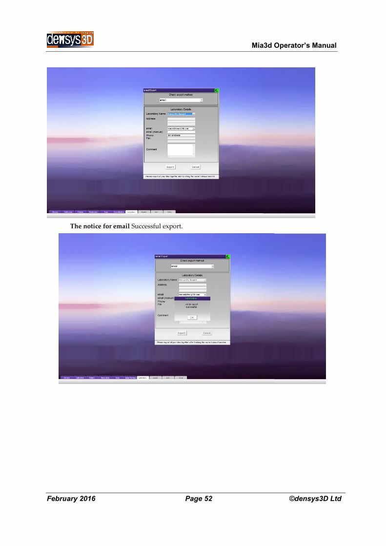
For E-mail
Mia3d Operator’s Manual
February 2016 Page 52 ©densys3D Ltd
The notice for email Successful export.
Mia3d Operator’s Manual
February 2016 Page 53 ©densys3D Ltd
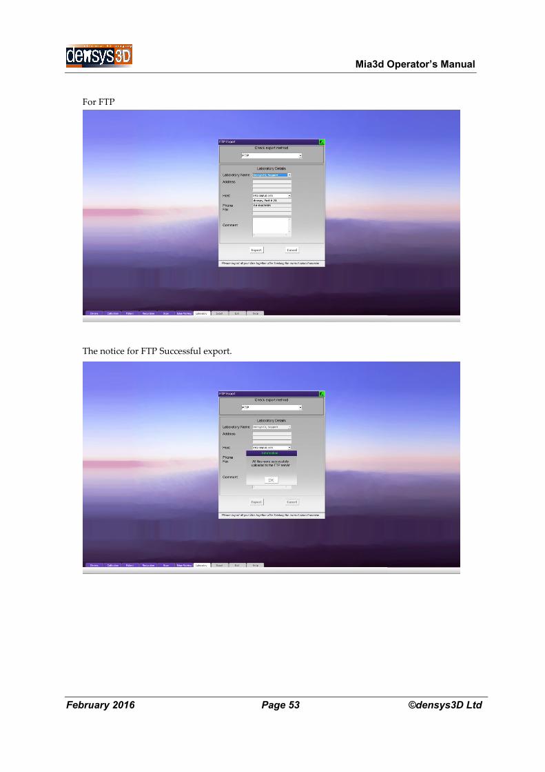
For FTP
The notice for FTP Successful export.
Mia3d Operator’s Manual
February 2016 Page 54 ©densys3D Ltd
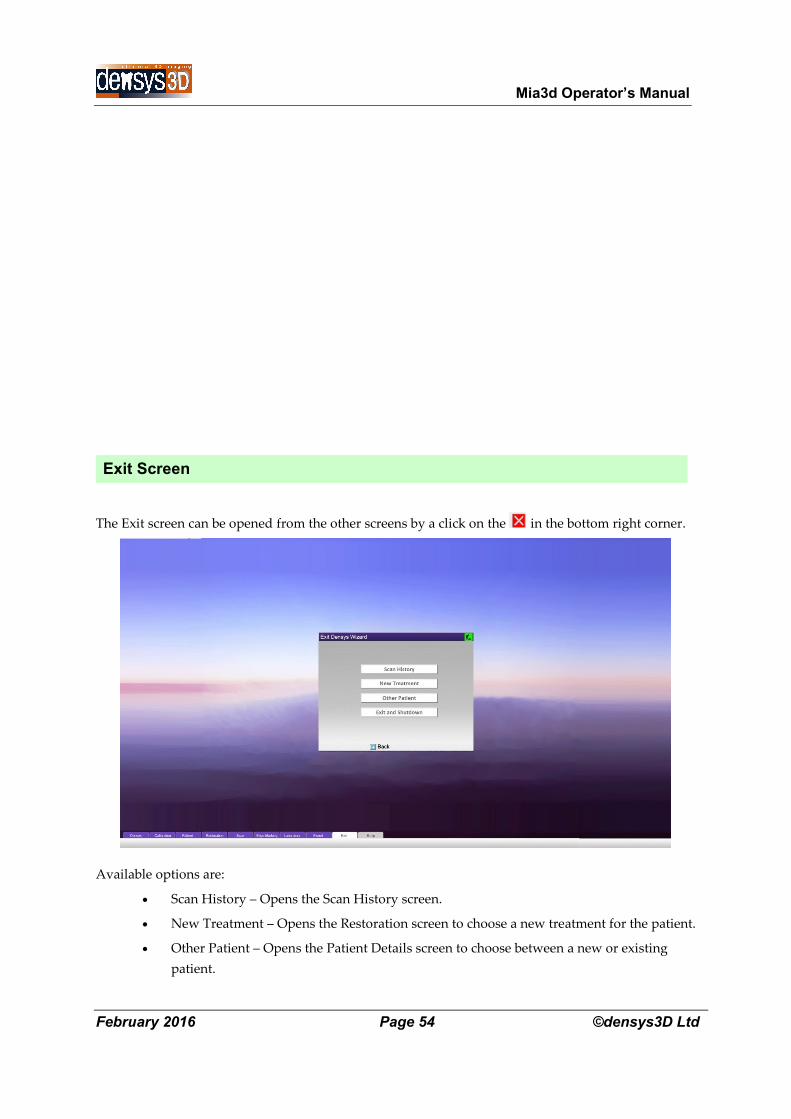
Exit Screen
The Exit screen can be opened from the other screens by a click on the in the bottom right corner.
Available options are:
Scan History – Opens the Scan History screen.
New Treatment – Opens the Restoration screen to choose a new treatment for the patient.
Other Patient – Opens the Patient Details screen to choose between a new or existing
patient.

Mia3d Operator’s Manual
February 2016 Page 55 ©densys3D Ltd
Exit and Shutdown – Shuts down the MIA3D program.

Mia3d Operator’s Manual
February 2016 Page 56 ©densys3D Ltd
Contact Information
For additional information and any inquires please contact:
Densys3D Ltd.
P.O. Box 804
Migdal Ha'Emek 23108 Israel
Tel: +972-4-644-3606
Fax: +972-4-654-0535