Embed Size (px)
Citation preview

www.metrixvibration.com • [email protected] • 281.940.1802 Doc# 1532538 • DATAWATCH IX • Oct 2016-RevE • Page 1 of 7
DATAWATCH IX MONITOR/RECORDERDatasheet
OVERVIEW
The DATAWATCH IX monitor offers an excellent graphical display and recording device for a box of its size. The compact panel mount unit offers four isolated or eight non-isolated high accuracy universal inputs for data display and recording. This data recording device is enhanced by a full color, ¼ VGA display to bring a crystal clear operator interface to even the smallest of machines.
The 88mm [3.5in] TFT display offers clear visualization of vibration and process parameters with a wide selection of configurable views to best suit the application. Views include: Horizontal and vertical trends, horizontal and vertical bar graphs, numeric, alarm panel, and alarm status. The unit also provides user configuration from the front of the product without the need to connect to a PC.
The DATAWATCH IX recording functionality utilizes 50MB onboard Flash memory, removable USB and/or data transfer via Ethernet communications. The four isolated or eight non-isolated universal input channels provide high accuracy and 125ms parallel sampling. An additional 30 virtual channels can be utilized to view modbus inputs, maths, counter and totalizer values within the instrument. Each temperature measurement uses one isolated or two adjacent non-isolated channels.
FEATURES AND BENEFITS• Automatic data recording• Panel mounted• High accuracy universal inputs• USB removable data storage facility• Compact design• 50MB flash memory• Modbus TCP/IP over Ethernet communications• ¼ VGA crystal clear display• 30 virtual channels• Multiple I/O options• Web server• Four isolated channels• Eight non-isolated channels
96mm [3.78in]
100mm [3.94in]

www.metrixvibration.com • [email protected] • 281.940.1802 Doc# 1532538 • DATAWATCH IX • Oct 2016-RevE • Page 2 of 7
DATAWATCH IX MONITOR/RECORDERDatasheet
SPECIFICATIONSGeneral
I/O Types Analog i/p: Four isolated or Eight non-isolated. Note that temperature takes up one analog input (Not dual channel).Digital i/p: TwoDigital (logic) o/p: TwoRelay o/p: FourFeatures:
- Modbus TCP master/slave- USB configuration save/restore- 30 Virtual channels (each configurable as counter, maths, totalizer or comms input)- Customized start up screen- Ethernet/IP
Environmental Performance
Ambient Temperature Range:Operating: 0 to 55°CStorage: –20 to +70°C
Humidity Range Operating: 5% to 85% RH non condensingStorage: 5% to 85% RH non condensing
Protection: Front panel: IP65
Behind Panel: IP10 (International)Shock/Vibration: BS EN61131-2 (5 to 150 Hz. at 1g; 1 octave per min.)Altitude: <2000 metresAtmosphere: Not suitable for use in explosive or corrosive atmospheresElectrical Safety: BS EN61010-1 (Installation category II; Pollution degree 2)Electromagnetic Compatibility Emissions
(Standard units): BS EN61326 Class B – Light industrial(Low voltage option): BS EN61326 Class A – Heavy industrial
Immunity: BS EN61326 Industrial
Approvals and Compliance
General: CE and cUL, EN61010PV input: AMS2750D compliantRoHS EU: ChinaPackaging: BS61131-2 section 2.1.3.3.
Physical
Panel Mounting: 1/4 DINWeight (Instrument only): 0.44kg (15.52oz)Panel Cutout Dimension: 92 mm x 92 mm (both -0.0 +0.8) or
3.62 in x 3.62 in (both -0.00 +0.03 in)Depth Behind Panel: 90 mm (3.54 in) excluding wiring
Operator Interface
Display: 3.5” TFT color display (320 pixels wide x 240 pixels high)Controls: Four navigation push buttons below the display screen Page, Scroll, Lower and Raise)
Power Requirements
Supply Voltage:Standard: 24 Vdc (+20%, -15%). See Power Supply Voltage for packaged systems on page 7.
Power Dissipation: 9W (max.)Fuse Type: No internal fuse fittedInterrupt Protection: Standard: Holdup >10ms at 85V RMS supply voltage
Battery Backup
Stored Data: Time, dateReplacement Period: Three years typicalClock (real-time clock) Data:
Support Time: Minimum of 1 year with unit unpoweredTemperature Stability: 0 to 55°C ≤±3.5ppmRTC Aging: First year to 10 year <± 5ppm
Type: Poly-carbon mono fluoride/lithium (BR2330) (PA260195)Replace battery with Panasonic BR2330/BE only. Use of another battery may present a risk of fire or explosion. See owners manual for safety instructions.
Caution Battery may explode if mistreated. Do not recharge, disassemble or dispose of in fire.
Ethernet Communications
Type: 10/100baseT Ethernet (IEEE802.3)Protocols: Modbus TCP/IP master/slave over EthernetCable type: Category 5Maximum length: 100m (110 yards)Termination:
RJ45Green LED illuminated = link connected;Amber LED flashing shows link activity
USB Port
Number of Ports: One at rear of instrumentStandard: USB1.1Transmission Speeds: 1.5MBit/sec (low speed device)Maximum Current: <100mAPeripherals Supported: Memory stick (8GB max), Bar code reader, QWERTY keyboard

www.metrixvibration.com • [email protected] • 281.940.1802 Doc# 1532538 • DATAWATCH IX • Oct 2016-RevE • Page 3 of 7
DATAWATCH IX MONITOR/RECORDERDatasheet
Update/Archive Rates
Sample Rate (input/output): 8HzTrend Update: 8Hz max.Archive Sample Value: Latest value at archive timeDisplay Value: Latest value at display update time
Analog Input
Number of Inputs: Four or EightInput Types: dc Volts, dc mV, dc mA, dual mA (external shunt
required), dual mV, Thermocouple, RTD (2-wire and 3-wire), Digital (Contact closure)
Input Type Mix: Freely configurableSample Rate: 8Hz (125ms) 4Hz (250ms) if dual input enabled
Conversion Method: 16 bit delta sigmaInput Ranges: See Table 1 and Table 2Mains Rejection (48 to 62Hz)
Series Mode: > 95dBCommon Mode: >179dB
Common Mode voltage: 250V ac max.Series Mode Voltage: 280mV at lowest range; 5V p-p at highest rangeInput Impedance:
40mV, 80mV, 2V ranges > 100MΩ;62.5kΩ for input voltages > 5.6V667kΩ for input ranges < 5.6V
Overvoltage ProtectionContinuous: ±30V RMSTransient (<1ms): ±200V pk-pk between terminals
Sensor Break Detection Type: ac sensor break on each input giving quick response with no associated dc errors
Recognition Time: <3 secondsMinimum Break Resistance: 40mV, 80mV ranges: 5kΩ; other ranges: 12.5kΩ
Shunt (mA inputs only): 1Ω to 1KΩ mounted externally Additional Error Due to Shunt: 0.1% of InputIsolation:
Channel to Channel: 300V RMS or
Note: If Dual Channel mode enabled primary and secondary inputs are not electrically isolated from each other.
Channel to Common Electronics: 300V RMS Channel to Ground: 300V RMS
Dielectric Strength Test: BS EN61010, 1 minute type testChannel to Channel: 2500V acChannel to Ground: 1500V ac
SPECIFICATIONS ContinuedTable 1 (Note: Restricted to 2000mV if dual input mode enabled)
Low Range
High Range Resolution
Max. Error (Instrument at
25°)Temp.
Performance
-40mV 40mV 1.9μV 4.6μV + 0.053% of reading
13ppm of input per °C
-80mV 80mV 3.2μV 7.5μV + 0.052% of reading
-2V 2V 82μV420μV +
0.044% of reading
-3V 3V 500μV1.5mV +
0.063% of reading
45ppm of input per °C
Resistance Input Ranges
Temperature Scale: ITS90Types, Ranges and Accuracies: See Table 3Maximum Source Current: 200μAPt100 Figures
Range: 0 to 400Ω (–200 to +850°C)Resolution: 0.05°CCalibration Error: ±0.31°C ±0.023% of measurement in °C at 25°C ambientTemperature Coefficient: ±0.01°C/°C ±25ppm/°C measurement in °C rom 25°C ambientMeasurement Noise: 0.05°C peak-peak with 1.6s input filterLinearity error: 0.0033% (best fit straight line)Lead resistance: 0 to 22Ω matched lead resistancesBulb current: 200μA nominal
Table 2 Ohms (RTD) Input Ranges
Low Range
High Range Resolution
Max. Error (Instrument at
25°)Temp.
Performance
0Ω 400Ω 20mΩ 120mΩ + 0.023% of reading
25ppm of input per °C
Table 3 RTD Type Details
RTD Type
Overall Range (°C) Standard
Max. Linearization
Error
Cu10 –20 to +400 General Electric Co. 0.02°C
Cu53 –70 to +200 RC21-4-1966
0.01°C
JPT100 –220 to +630 JIS C1604:1989
Ni100 –60 to + 250 DIN43760:1987
Ni120 –50 to +170 DIN43760:1987
Pt100 –200 to + 850 IEC751
Pt100A –200 to + 600 Recorders SA 0.09°C
www.metrixvibration.com • [email protected] • 281.940.1802 Doc# 1532538 • DATAWATCH IX • Oct 2016-RevE • Page 4 of 7
DATAWATCH IX MONITOR/RECORDERDatasheet
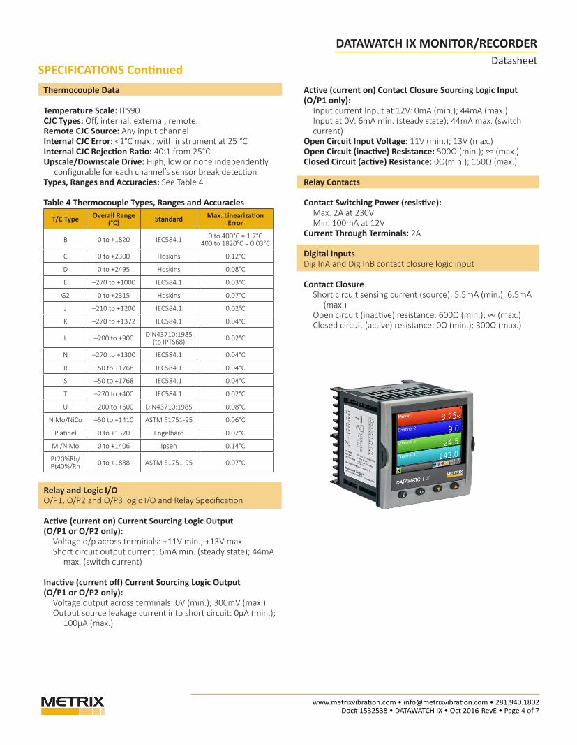
Thermocouple Data
Temperature Scale: ITS90CJC Types: Off, internal, external, remote.Remote CJC Source: Any input channelInternal CJC Error: <1°C max., with instrument at 25 °CInternal CJC Rejection Ratio: 40:1 from 25°CUpscale/Downscale Drive: High, low or none independently configurable for each channel’s sensor break detectionTypes, Ranges and Accuracies: See Table 4
Table 4 Thermocouple Types, Ranges and Accuracies
T/C Type Overall Range (°C) Standard Max. Linearization
Error
B 0 to +1820 IEC584.1 0 to 400°C = 1.7°C400 to 1820°C = 0.03°C
C 0 to +2300 Hoskins 0.12°C
D 0 to +2495 Hoskins 0.08°C
E –270 to +1000 IEC584.1 0.03°C
G2 0 to +2315 Hoskins 0.07°C
J –210 to +1200 IEC584.1 0.02°C
K –270 to +1372 IEC584.1 0.04°C
L –200 to +900 DIN43710:1985(to IPTS68) 0.02°C
N –270 to +1300 IEC584.1 0.04°C
R –50 to +1768 IEC584.1 0.04°C
S –50 to +1768 IEC584.1 0.04°C
T –270 to +400 IEC584.1 0.02°C
U –200 to +600 DIN43710:1985 0.08°C
NiMo/NiCo –50 to +1410 ASTM E1751-95 0.06°C
Platinel 0 to +1370 Engelhard 0.02°C
Mi/NiMo 0 to +1406 Ipsen 0.14°C
Pt20%Rh/Pt40%/Rh 0 to +1888 ASTM E1751-95 0.07°C
Relay and Logic I/OO/P1, O/P2 and O/P3 logic I/O and Relay Specification
Active (current on) Current Sourcing Logic Output(O/P1 or O/P2 only):
Voltage o/p across terminals: +11V min.; +13V max.Short circuit output current: 6mA min. (steady state); 44mA max. (switch current)
Inactive (current off) Current Sourcing Logic Output(O/P1 or O/P2 only):
Voltage output across terminals: 0V (min.); 300mV (max.)Output source leakage current into short circuit: 0μA (min.); 100μA (max.)
SPECIFICATIONS ContinuedActive (current on) Contact Closure Sourcing Logic Input (O/P1 only):
Input current Input at 12V: 0mA (min.); 44mA (max.)Input at 0V: 6mA min. (steady state); 44mA max. (switch current)
Open Circuit Input Voltage: 11V (min.); 13V (max.)Open Circuit (inactive) Resistance: 500Ω (min.); ∞ (max.)Closed Circuit (active) Resistance: 0Ω(min.); 150Ω (max.)
Relay Contacts
Contact Switching Power (resistive): Max. 2A at 230V Min. 100mA at 12V
Current Through Terminals: 2A
Digital InputsDig InA and Dig InB contact closure logic input
Contact ClosureShort circuit sensing current (source): 5.5mA (min.); 6.5mA (max.)Open circuit (inactive) resistance: 600Ω (min.); ∞ (max.)Closed circuit (active) resistance: 0Ω (min.); 300Ω (max.)

www.metrixvibration.com • [email protected] • 281.940.1802 Doc# 1532538 • DATAWATCH IX • Oct 2016-RevE • Page 5 of 7
DATAWATCH IX MONITOR/RECORDERDatasheet
REAR TERMINALS
Analog Input 1
Analog Input 2
Analog Input 3
Analog Input 4
Output 1
Output 2
Digital Input A
Output 3
Supply Voltage
Ethernet (RJ45)
USB
Digital Input B
Output 4
Output 5
Safety Ground
Mains (Line) SupplyVoltage Wiring
24 Vdc (+20%, -15%) (polarity irrelevant)
TERMINATION DETAILS
The screw terminals accept wire sizes in the range:Single wire 0.205 to 2.08mm² (14 to 24 AWG) 2 wires 0.205 to 1.31mm² (16 to 24 AWG) inclusive.Screw terminals should be tightened to a torque not exceeding 0.4Nm (3.54 lb in).
Use copper conductors only.
The power supply input is not fused protected. This should be provided externally.
Each wire connected to LA, LB and LC must be less than 30m in length.
Note: Temperature takes up one analog input (Not dual channel).
See packaged systems for other input voltage types (pg 7).

www.metrixvibration.com • [email protected] • 281.940.1802 Doc# 1532538 • DATAWATCH IX • Oct 2016-RevE • Page 6 of 7
DATAWATCH IX MONITOR/RECORDERDatasheet
ISOLATION INSTALLATION
100 to 230V ac 115% at 48 to 62Hz

www.metrixvibration.com • [email protected] • 281.940.1802 Doc# 1532538 • DATAWATCH IX • Oct 2016-RevE • Page 7 of 7
DATAWATCH IX MONITOR/RECORDERDatasheet
HOW TO ORDER
AA Dual Input Channels04 4 inputs isolated
08 8 inputs non isolated
A ADW - IX -
BB Panel Type
03 NEMA 4X wall mount polycarbonate enclosure front hinged door complete with wall mounting brackets. Datawatch mounted in the door and wired to a termination assembly complete with 240/120VAC 2 amp circuit breaker. Front panel mount NEMA 4X USB port.Integral 24V DC power supply wired to power up to eight (8) vibration transmitters and the Datawatch IX monitor.
04 NEMA 4X wall mount 316 stainless steel enclosure front hinged door complete with wall mounting brackets.Datawatch mounted in the door and wired to a termination assembly complete with 240/120VAC 2 amp circuit breaker.Front panel mount NEMA 4X USB port.Integral 24V DC power supply wired to power up to eight (8) vibration transmitters and the Datawatch IX monitor.
05 NEMA 4X wall mount polycarbonate enclosure with transparent window in front hinged door complete with wall mounting brackets. Datawatch is mounted to the swingout door, inside the enclosure, and wired to a termination assembly complete with 240/120VAC 2 amp circuit breaker. The USB port is on the back side of the DATAWATCH IX.Integral 24V DC power supply wired to power up to eight (8) vibration transmitters and the Datawatch IX monitor.
06 NEMA 4X wall mount 316 stainless steel enclosure with transparent window in front hinged door complete with wall mounting brackets.Datawatch is mounted to the swingout door, inside the enclosure, and wired to a termination assembly complete with 240/120VAC 2 amp circuit breaker.The USB port is on the back side of the DATAWATCH IX.Integral 24V DC power supply wired to power up to eight (8) vibration transmitters and the Datawatch IX monitor.
B B
Enclosure Dimensions: 10 W x 12 H x 8.7 D (in)255 W x 305 H x 221 D (mm)
Enclosure Dimensions: 8.6 W x 10.6 H x 7.6 D (in)218.4 W x 269.2 H x 193 D (mm)
NOTE: The DATAWATCH IX systems are factory configured for four (4) isolated or eight (8) non-isolated, 4 to 20 mA vibration transmitters (0 to 1.0 ips (0 to 25 mm/s)) with alarm levels set at 0.3 ips (8 mm/s). Users may reconfigure as required.
Swingout door


![Atmel ATmega16U4, ATmega32U4 Datasheet …...ATmega16U4/32U4 [DATASHEET] 8](https://img.pdfslide.us/doc/110x75/5f0a39897e708231d42a9d86/-atmel-atmega16u4-atmega32u4-datasheet-atmega16u432u4-datasheet-8.jpg)