Embed Size (px)
Citation preview
Operating Instructions
METRAHIT27 and METRAHITH+E CARMETRA HIT 27M: Digital Multimeter and MilliohmmeterMETRA HIT 27I: Digital Multimeter, Milliohmmeter and MegohmmeterMETRA HIT H+E CAR: Mega Tester for Hybrid E-cars
3-349-207-0213/3.17
2 GMC-I Messtechnik GmbH
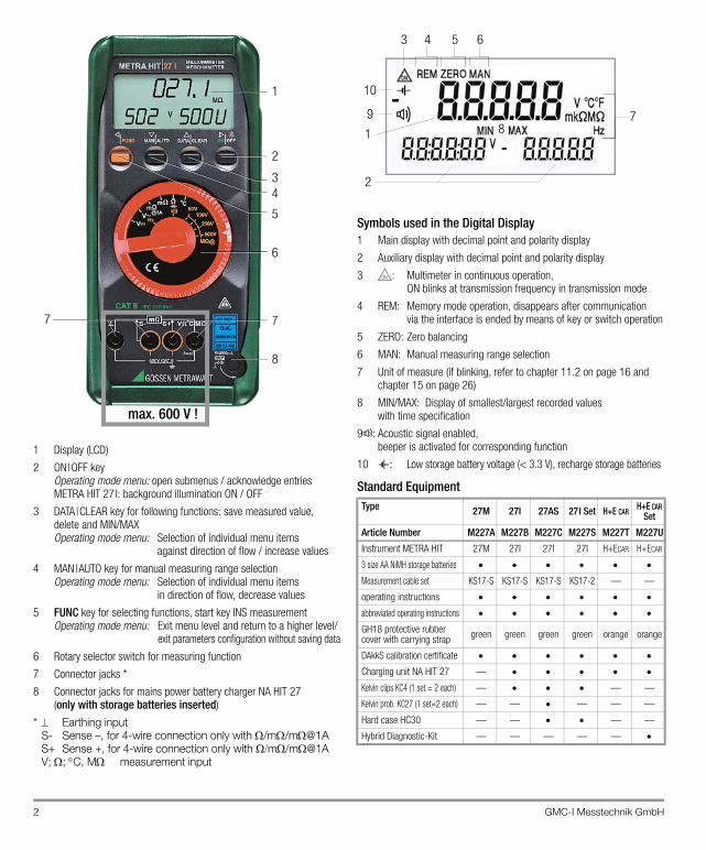
1 Display (LCD)
2 ON|OFF key Operating mode menu: open submenus / acknowledge entriesMETRA HIT 27I: background illumination ON / OFF
3 DATA|CLEAR key for following functions: save measured value, delete and MIN/MAX Operating mode menu: Selection of individual menu items
against direction of flow / increase values
4 MAN|AUTO key for manual measuring range selection Operating mode menu: Selection of individual menu items
in direction of flow, decrease values
5 FUNC key for selecting functions, start key INS measurementOperating mode menu: Exit menu level and return to a higher level/
exit parameters configuration without saving data
6 Rotary selector switch for measuring function
7 Connector jacks *
8 Connector jacks for mains power battery charger NA HIT 27 (only with storage batteries inserted)
* Earthing inputS- Sense –, for 4-wire connection only with /m/m@1AS+ Sense +, for 4-wire connection only with m/m@1AV; ; C, M measurement input
Symbols used in the Digital Display1 Main display with decimal point and polarity display
2 Auxiliary display with decimal point and polarity display
3 : Multimeter in continuous operation, ON blinks at transmission frequency in transmission mode
4 REM: Memory mode operation, disappears after communication via the interface is ended by means of key or switch operation
5 ZERO: Zero balancing
6 MAN: Manual measuring range selection
7 Unit of measure (if blinking, refer to chapter 11.2 on page 16 and chapter 15 on page 26)
8 MIN/MAX: Display of smallest/largest recorded valueswith time specification
9 : Acoustic signal enabled, beeper is activated for corresponding function
10 : Low storage battery voltage (< 3.3 V), recharge storage batteries
Standard Equipment
1
2
34
5
6
8
7 7
max. 600 V !
Type 27M 27I 27AS 27I Set H+E CARH+E CAR
Set
Article Number M227A M227B M227C M227S M227T M227U
Instrument METRA HIT 27M 27I 27I 27I H+ECAR H+ECAR
3 size AA NiMH storage batteries
Measurement cable set KS17-S KS17-S KS17-S KS17-2 — —
operating instructions
abbreviated operating instructions
GH18 protective rubber cover with carrying strap green green green green orange orange
DAkkS calibration certificate
Charging unit NA HIT 27 —
Kelvin clips KC4 (1 set = 2 each) — — —
Kelvin prob. KC27 (1 set=2 each) — — — — —
Hard case HC30 — — — —
Hybrid Diagnostic-Kit — — — — —
1
10
9
64 53
78
2
GMC-I Messtechnik GmbH 3
Table of ContentsPage Page
1 Safety Features and Precautions ...............................4
2 Initial Start-Up ............................................................5
3 Selecting Measuring Functions and Measuring Ranges .......................................................................6
3.1 Automatic Measuring Range Selection ..................................... 63.2 Manual Measuring Range Selection ......................................... 63.3 Quick Measurements .............................................................. 7
4 Triple Digital Display ..................................................7
5 Measured Value Storage ............................................85.1 Measured Value Storage – Key Function “DATA”
(Hold/Compare) ...................................................................... 8
6 Saving Minimum and Maximum Values “MIN/MAX” with Time Stamp .....................................9
7 Voltage and Frequency Measurement ......................107.1 Voltage Measurement [V] ...................................................... 107.1.1 Zero Balancing in the 3 V DC Measuring Range ...................... 107.2 Frequency Measurement [Hz] ................................................ 10
8 Resistance and Diode Measurements ......................118.1 Resistance Measurement (2-wire connection) [] .................. 118.1.1 Zero Balancing in the 300 and 3 k Measuring Ranges ..... 118.2 Continuity Test during Resistance Measurement .................... 128.3 Diode Measurements ........................................................... 12
9 Milliohm Measurement (4-Pole-Measurement) .......139.1 Compensation of Cable Resistance ........................................ 139.1.1 Measurement with Kelvin Probe KC27 ................................... 139.2 Thermovoltage Compensation ................................................ 139.3 Milliohm Measurement with 200 mA or 20 mA DC [m] ........ 149.4 Milliohm Measurement with 1 A Pulsating Measuring
Current [m@1 A] (automatic thermovoltage correction in 3 300 m range) ...........14
10 Temperature Measurement [C] ..............................14
11 Insulation Resistance Measurement [[email protected]] (METRA HIT 27I and METRA HIT H+E CAR only) ........15
11.1 Preparing for Measurement ................................................... 1511.2 Insulation Resistance Measurement ....................................... 1611.3 Ending the Measurement and Discharging .............................. 16
12 Using the Menus – from the Initial InFO Menu to Operating and Measuring Parameters ..................... 17
12.1 Sampling rAtE ...........................................................1712.2 Saving Measured Values ....................................................... 1712.2.1Memory Mode – DATA Key Function (see also chapter 5.1) ..... 1712.2.2Memory Mode Operation – STORE Menu Function .................. 1812.3 Querying Memory Occupancy – INFO MEMO/OCCUP ......... 1812.4 Clearing the Memory – MEMO CLEAr ................................ 1812.5 Activating the Default Values ................................................. 1812.6 Transmission Mode Operation with RS 232 Interface .............. 19
13 Characteristic Values ..................................... 22
14 Maintenance ............................................................ 2514.1 Storage Batteries and Batteries ............................................. 2514.2 Fuses ................................................................................... 2614.3 Housing ............................................................................... 2614.4 Device Return and Environmentally Compatible Disposal ......... 26
15 Multimeter Messages .............................................. 26
16 Accessories ............................................................. 27
17 Repair and Replacement Parts Service,Calibration Center* and Rental Instrument Service . 27
18 Guarantee ................................................................ 28
19 Product Support ....................................................... 28
20 Recalibration ............................................................ 28
4 GMC-I Messtechnik GmbH
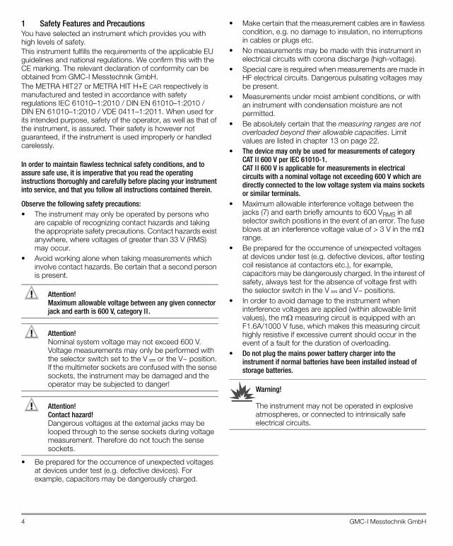
1 Safety Features and PrecautionsYou have selected an instrument which provides you with high levels of safety. This instrument fulfills the requirements of the applicable EU guidelines and national regulations. We confirm this with the CE marking. The relevant declaration of conformity can be obtained from GMC-I Messtechnik GmbH.The METRA HIT27 or METRA HIT H+E CAR respectively is manufactured and tested in accordance with safety regulations IEC 61010–1:2010 / DIN EN 61010–1:2010 / DIN EN 61010–1:2010 / VDE 0411–1:2011. When used for its intended purpose, safety of the operator, as well as that of the instrument, is assured. Their safety is however not guaranteed, if the instrument is used improperly or handled carelessly.
In order to maintain flawless technical safety conditions, and to assure safe use, it is imperative that you read the operating instructions thoroughly and carefully before placing your instrument into service, and that you follow all instructions contained therein.
Observe the following safety precautions:• The instrument may only be operated by persons who
are capable of recognizing contact hazards and taking the appropriate safety precautions. Contact hazards exist anywhere, where voltages of greater than 33 V (RMS) may occur.
• Avoid working alone when taking measurements which involve contact hazards. Be certain that a second person is present.
Attention!!Maximum allowable voltage between any given connector jack and earth is 600 V, category I I .
Attention!!Nominal system voltage may not exceed 600 V. Voltage measurements may only be performed with the selector switch set to the V or the V~ position.If the multimeter sockets are confused with the sense sockets, the instrument may be damaged and the operator may be subjected to danger!
Attention!!Contact hazard!Dangerous voltages at the external jacks may be looped through to the sense sockets during voltage measurement. Therefore do not touch the sense sockets.
• Be prepared for the occurrence of unexpected voltages at devices under test (e.g. defective devices). For example, capacitors may be dangerously charged.
• Make certain that the measurement cables are in flawless condition, e.g. no damage to insulation, no interruptions in cables or plugs etc.
• No measurements may be made with this instrument in electrical circuits with corona discharge (high-voltage).
• Special care is required when measurements are made in HF electrical circuits. Dangerous pulsating voltages may be present.
• Measurements under moist ambient conditions, or with an instrument with condensation moisture are not permitted.
• Be absolutely certain that the measuring ranges are not overloaded beyond their allowable capacities. Limit values are listed in chapter 13 on page 22.
• The device may only be used for measurements of category CAT I I 600 V per IEC 61010-1. CAT I I 600 V is applicable for measurements in electrical circuits with a nominal voltage not exceeding 600 V which are directly connected to the low voltage system via mains sockets or similar terminals.
• Maximum allowable interference voltage between the jacks (7) and earth briefly amounts to 600 VRMS in all selector switch positions in the event of an error. The fuse blows at an interference voltage value of > 3 V in the m range.
• Be prepared for the occurrence of unexpected voltages at devices under test (e.g. defective devices, after testing coil resistance at contactors etc.), for example, capacitors may be dangerously charged. In the interest of safety, always test for the absence of voltage first with the selector switch in the V and V~ positions.
• In order to avoid damage to the instrument when interference voltages are applied (within allowable limit values), the m measuring circuit is equipped with an F1.6A/1000 V fuse, which makes this measuring circuit highly resistive if excessive current should occur in the event of a fault for the duration of overloading.
• Do not plug the mains power battery charger into the instrument if normal batteries have been installed instead of storage batteries.
Warning!
The instrument may not be operated in explosive atmospheres, or connected to intrinsically safe electrical circuits.
GMC-I Messtechnik GmbH 5
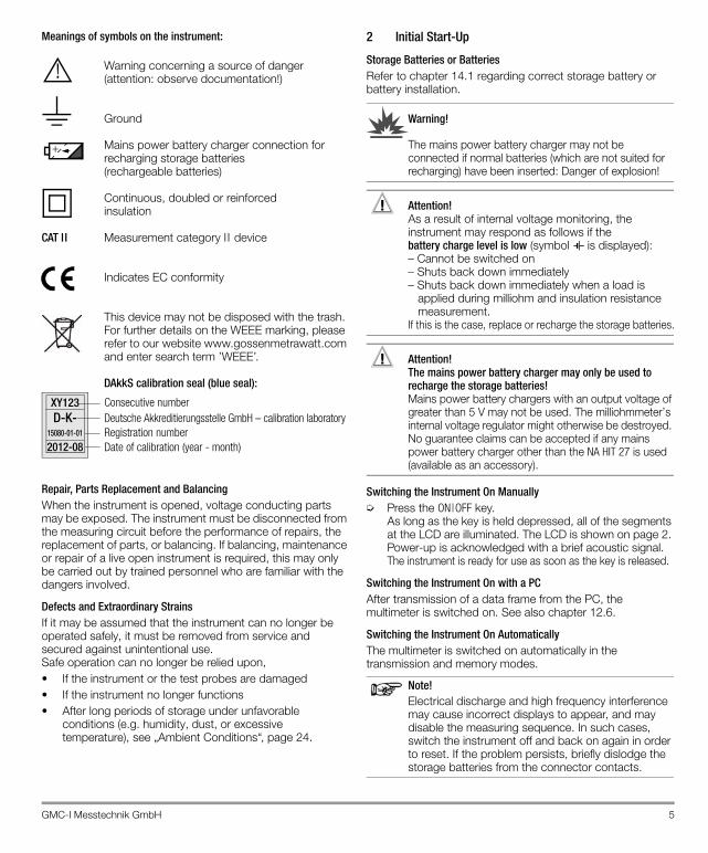
Meanings of symbols on the instrument:
Warning concerning a source of danger(attention: observe documentation!)
Ground
Mains power battery charger connection for recharging storage batteries(rechargeable batteries)
Continuous, doubled or reinforced insulation
CAT II Measurement category I I device
Indicates EC conformity
This device may not be disposed with the trash. For further details on the WEEE marking, please refer to our website www.gossenmetrawatt.com and enter search term ’WEEE’.
DAkkS calibration seal (blue seal):
Repair, Parts Replacement and BalancingWhen the instrument is opened, voltage conducting parts may be exposed. The instrument must be disconnected from the measuring circuit before the performance of repairs, the replacement of parts, or balancing. If balancing, maintenance or repair of a live open instrument is required, this may only be carried out by trained personnel who are familiar with the dangers involved.
Defects and Extraordinary StrainsIf it may be assumed that the instrument can no longer be operated safely, it must be removed from service and secured against unintentional use.Safe operation can no longer be relied upon,• If the instrument or the test probes are damaged• If the instrument no longer functions• After long periods of storage under unfavorable
conditions (e.g. humidity, dust, or excessive temperature), see „Ambient Conditions“, page 24.
2 Initial Start-Up
Storage Batteries or BatteriesRefer to chapter 14.1 regarding correct storage battery or battery installation.
Warning!
The mains power battery charger may not be connected if normal batteries (which are not suited for recharging) have been inserted: Danger of explosion!
Attention!!As a result of internal voltage monitoring, the instrument may respond as follows if the battery charge level is low (symbol is displayed): – Cannot be switched on – Shuts back down immediately – Shuts back down immediately when a load is
applied during milliohm and insulation resistance measurement.
If this is the case, replace or recharge the storage batteries.
Attention!!The mains power battery charger may only be used to recharge the storage batteries!Mains power battery chargers with an output voltage of greater than 5 V may not be used. The milliohmmeter’s internal voltage regulator might otherwise be destroyed. No guarantee claims can be accepted if any mains power battery charger other than the NA HIT 27 is used (available as an accessory).
Switching the Instrument On Manually➭ Press the ON|OFF key.
As long as the key is held depressed, all of the segments at the LCD are illuminated. The LCD is shown on page 2. Power-up is acknowledged with a brief acoustic signal. The instrument is ready for use as soon as the key is released.
Switching the Instrument On with a PCAfter transmission of a data frame from the PC, the multimeter is switched on. See also chapter 12.6.
Switching the Instrument On AutomaticallyThe multimeter is switched on automatically in the transmission and memory modes.
Note!Electrical discharge and high frequency interference may cause incorrect displays to appear, and may disable the measuring sequence. In such cases, switch the instrument off and back on again in order to reset. If the problem persists, briefly dislodge the storage batteries from the connector contacts.
!
+
Consecutive number
Registration numberDate of calibration (year - month)
Deutsche Akkreditierungsstelle GmbH – calibration laboratory XY123
2012-08
D-K-15080-01-01
6 GMC-I Messtechnik GmbH
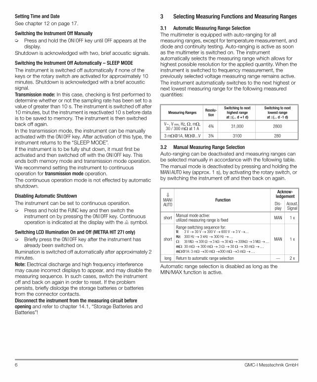
Setting Time and DateSee chapter 12 on page 17.
Switching the Instrument Off Manually➭ Press and hold the ON|OFF key until OFF appears at the
display.Shutdown is acknowledged with two, brief acoustic signals.
Switching the Instrument Off Automatically – SLEEP MODEThe instrument is switched off automatically if none of the keys or the rotary switch are activated for approximately 10 minutes. Shutdown is acknowledged with a brief acoustic signal.Transmission mode: In this case, checking is first performed to determine whether or not the sampling rate has been set to a value of greater than 10 s. The instrument is switched off after 10 minutes, but the instrument is reactivated 10 s before data is to be saved to memory. The instrument is then switched back off again.In the transmission mode, the instrument can be manually activated with the ON|OFF key. After activation of this type, the instrument returns to the “SLEEP MODE”.If the instrument is to be fully shut down, it must first be activated and then switched off with the ON|OFF key. This ends both memory mode and transmission mode operation.We recommend setting the instrument to continuous operation for transmission mode operation.The continuous operation mode is not effected by automatic shutdown.
Disabling Automatic ShutdownThe instrument can be set to continuous operation.➭ Press and hold the FUNC key and then switch the
instrument on by pressing the ON|OFF key. Continuous operation is indicated at the display with the symbol.
Switching LCD Illumination On and Off (METRA HIT 27I only)➭ Briefly press the ON|OFF key after the instrument has
already been switched on.Illumination is switched off automatically after approximately 2 minutes.Note: Electrical discharge and high frequency interference may cause incorrect displays to appear, and may disable the measuring sequence. In such cases, switch the instrument off and back on again in order to reset. If the problem persists, briefly dislodge the storage batteries or batteries from the connector contacts.Disconnect the instrument from the measuring circuit before opening and refer to chapter 14.1, “Storage Batteries and Batteries”!
3 Selecting Measuring Functions and Measuring Ranges
3.1 Automatic Measuring Range SelectionThe multimeter is equipped with auto-ranging for all measuring ranges, except for temperature measurement, and diode and continuity testing. Auto-ranging is active as soon as the multimeter is switched on. The instrument automatically selects the measuring range which allows for highest possible resolution for the applied quantity. When the instrument is switched to frequency measurement, the previously selected voltage measuring range remains active.The instrument automatically switches to the next highest or next lowest measuring range for the following measured quantities:
3.2 Manual Measuring Range SelectionAuto-ranging can be deactivated and measuring ranges can be selected manually in accordance with the following table.The manual mode is deactivated by pressing and holding the MAN|AUTO key (approx. 1 s), by activating the rotary switch, or by switching the instrument off and then back on again.
Automatic range selection is disabled as long as the MIN/MAX function is active.
Measuring Ranges Resolu-tion
Switching to next highest rangeat (... d +1 d)
Switching to next lowest rangeat (... d -1 d)
V~, V , Hz, m30 / 300 m at 1 A 4¾ 31,000 2800
3 m@1A, [email protected] 3¾ 3100 280
MAN|AUTO
Function
Acknow-ledgement
Dis-play
Acoust.Signal
short Manual mode active:utilized measuring range is fixed MAN 1 x
short
Range switching sequence for:V: 3 V 30 V 300 V 600 V 3 V Hz: 300 Hz 3 kHz 300 Hz : 30 M 300 3 k 30 k300k 3 Mm: 30 m 300 m3 30 30 mm@1A: 3 m30 m300 m3 m
MAN 1 x
long Return to automatic range selection — 2 x
GMC-I Messtechnik GmbH 7
3.3 Quick MeasurementsIf you wish to perform quicker measurements than those pos-sible with the automatic measuring range selection function, make sure to establish the appropriate measuring range:• by manual measuring range selection, i. e. by selecting the
measuring range with the best resolution, see chapter 3.2.
or• via DATA function, see chapter 5. After the first measure-
ment, the proper measuring range will be automatically determined so that measurements are performed more rapidly from the second measured value onwards.
With both functions, the established measuring range is maintained for the subsequent series mode measurments.
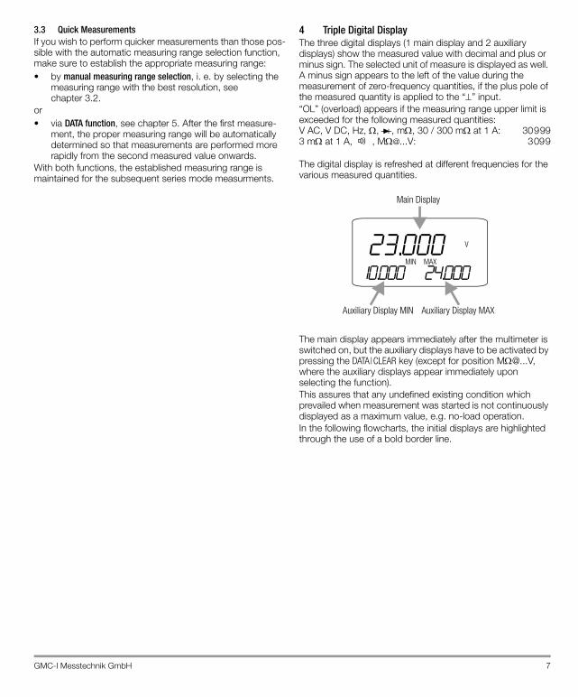
4 Triple Digital DisplayThe three digital displays (1 main display and 2 auxiliary displays) show the measured value with decimal and plus or minus sign. The selected unit of measure is displayed as well. A minus sign appears to the left of the value during the measurement of zero-frequency quantities, if the plus pole of the measured quantity is applied to the “” input. “OL” (overload) appears if the measuring range upper limit is exceeded for the following measured quantities: V AC, V DC, Hz, , , m, 30 / 300 m at 1 A: 309993 m at 1 A, , [email protected]: 3099
The digital display is refreshed at different frequencies for the various measured quantities.
The main display appears immediately after the multimeter is switched on, but the auxiliary displays have to be activated by pressing the DATA|CLEAR key (except for position [email protected], where the auxiliary displays appear immediately upon selecting the function).This assures that any undefined existing condition which prevailed when measurement was started is not continuously displayed as a maximum value, e.g. no-load operation.In the following flowcharts, the initial displays are highlighted through the use of a bold border line.
23.000MIN MAX
10.000 24.000
V
Auxiliary Display MIN
Main Display
Auxiliary Display MAX
8 GMC-I Messtechnik GmbH
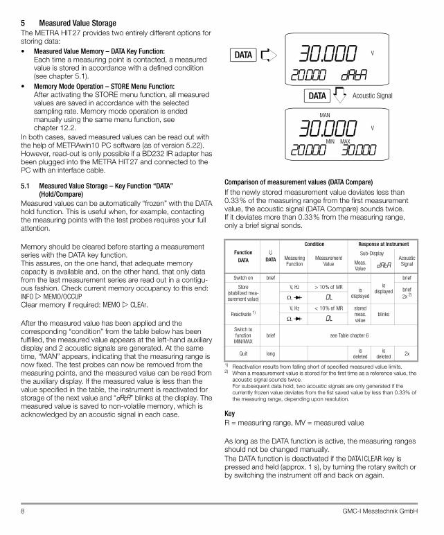
5 Measured Value StorageThe METRA HIT27 provides two entirely different options for storing data:• Measured Value Memory – DATA Key Function:
Each time a measuring point is contacted, a measured value is stored in accordance with a defined condition (see chapter 5.1).
• Memory Mode Operation – STORE Menu Function: After activating the STORE menu function, all measured values are saved in accordance with the selected sampling rate. Memory mode operation is ended manually using the same menu function, see chapter 12.2.
In both cases, saved measured values can be read out with the help of METRAwin10 PC software (as of version 5.22). However, read-out is only possible if a BD232 IR adapter has been plugged into the METRA HIT27 and connected to the PC with an interface cable.
5.1 Measured Value Storage – Key Function “DATA”(Hold/Compare)
Measured values can be automatically “frozen” with the DATA hold function. This is useful when, for example, contacting the measuring points with the test probes requires your full attention.
Memory should be cleared before starting a measurement series with the DATA key function. This assures, on the one hand, that adequate memory capacity is available and, on the other hand, that only data from the last measurement series are read out in a contigu-ous fashion. Check current memory occupancy to this end: INFO MEMO/OCCUP Clear memory if required: MEMO CLEAr.
After the measured value has been applied and the corresponding “condition” from the table below has been fulfilled, the measured value appears at the left-hand auxiliary display and 2 acoustic signals are generated. At the same time, “MAN” appears, indicating that the measuring range is now fixed. The test probes can now be removed from the measuring points, and the measured value can be read from the auxiliary display. If the measured value is less than the value specified in the table, the instrument is reactivated for storage of the next value and “data” blinks at the display. The measured value is saved to non-volatile memory, which is acknowledged by an acoustic signal in each case.
Comparison of measurement values (DATA Compare)If the newly stored measurement value deviates less than 0.33% of the measuring range from the first measurement value, the acoustic signal (DATA Compare) sounds twice. If it deviates more than 0.33% from the measuring range, only a brief signal sonds.
1) Reactivation results from falling short of specified measured value limits.2) When a measurement value is stored for the first time as a reference value, the
acoustic signal sounds twice. For subsequent data hold, two acoustic signals are only generated if the currently frozen value deviates from the fist saved value by less than 0.33% of the measuring range, depending upon resolution.
KeyR = measuring range, MV = measured value
As long as the DATA function is active, the measuring ranges should not be changed manually.The DATA function is deactivated if the DATA|CLEAR key is pressed and held (approx. 1 s), by turning the rotary switch or by switching the instrument off and back on again.
FunctionDATA
DATA
Condition Response at Instrument
Measuring Function
Measurement Value
Sub-DisplayAcousticSignalMeas.
Value DATA
Switch on briefis
displayed
brief
Store(stabilized mea-surement value)
V, Hz > 10% of MR is displayed
brief2x 2), 0 L
Reactivate 1)V, Hz < 10% of MR stored
meas. value
blinks, 0 L
Switch tofunction
MIN/MAXbrief see Table chapter 6
Quit long isdeleted
isdeleted 2x
Acoustic Signal
30.00020.000 data
V
30.000MIN MAX
20.000 30.000
V
DATA
DATA
MAN
GMC-I Messtechnik GmbH 9
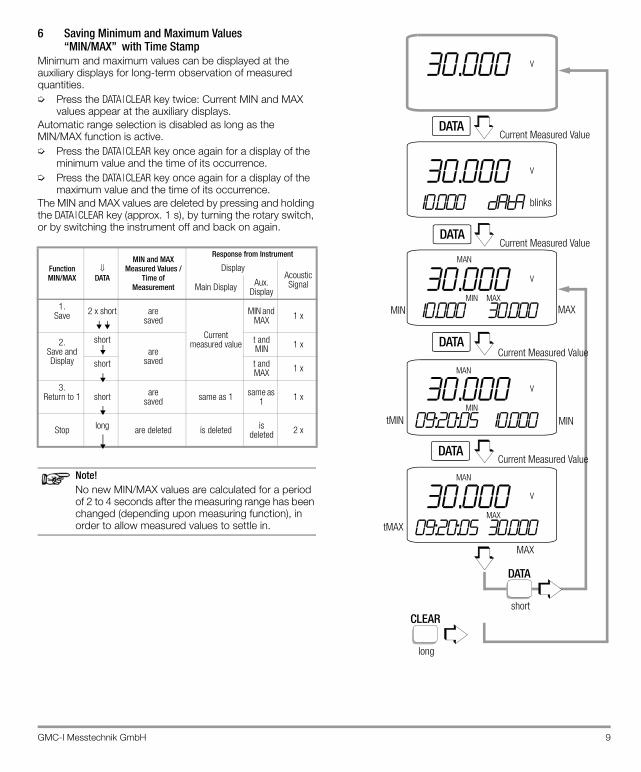
6 Saving Minimum and Maximum Values “MIN/MAX” with Time Stamp
Minimum and maximum values can be displayed at the auxiliary displays for long-term observation of measured quantities.➭ Press the DATA|CLEAR key twice: Current MIN and MAX
values appear at the auxiliary displays.Automatic range selection is disabled as long as the MIN/MAX function is active.➭ Press the DATA|CLEAR key once again for a display of the
minimum value and the time of its occurrence.➭ Press the DATA|CLEAR key once again for a display of the
maximum value and the time of its occurrence.The MIN and MAX values are deleted by pressing and holding the DATA|CLEAR key (approx. 1 s), by turning the rotary switch, or by switching the instrument off and back on again.
Note!No new MIN/MAX values are calculated for a period of 2 to4 seconds after the measuring range has been changed (depending upon measuring function), in order to allow measured values to settle in.
FunctionMIN/MAX
DATA
MIN and MAXMeasured Values /
Time of Measurement
Response from Instrument
DisplayAcousticSignalMain Display Aux.
Display
1.Save 2 x short are
saved
Current measured value
MIN and MAX 1 x
2.Save and Display
shortare
saved
t and MIN 1 x
short t and MAX 1 x
3. Return to 1 short are
saved same as 1 same as 1 1 x
Stop long are deleted is deleted is deleted 2 x
CLEAR
long
MIN MAX
tMIN MIN
tMAX
MAX
Current Measured Value
Current Measured Value
Current Measured Value
Current Measured Value
DATA
short
30.000 V
30.00010.000 data
V
30.000MIN MAX
10.000 30.000
V
30.000MIN
09:20:05 10.000
V
30.000MAX
09:20:05 30.000
V
DATA
DATA
DATA
DATA
MAN
MAN
MAN
blinks
10 GMC-I Messtechnik GmbH
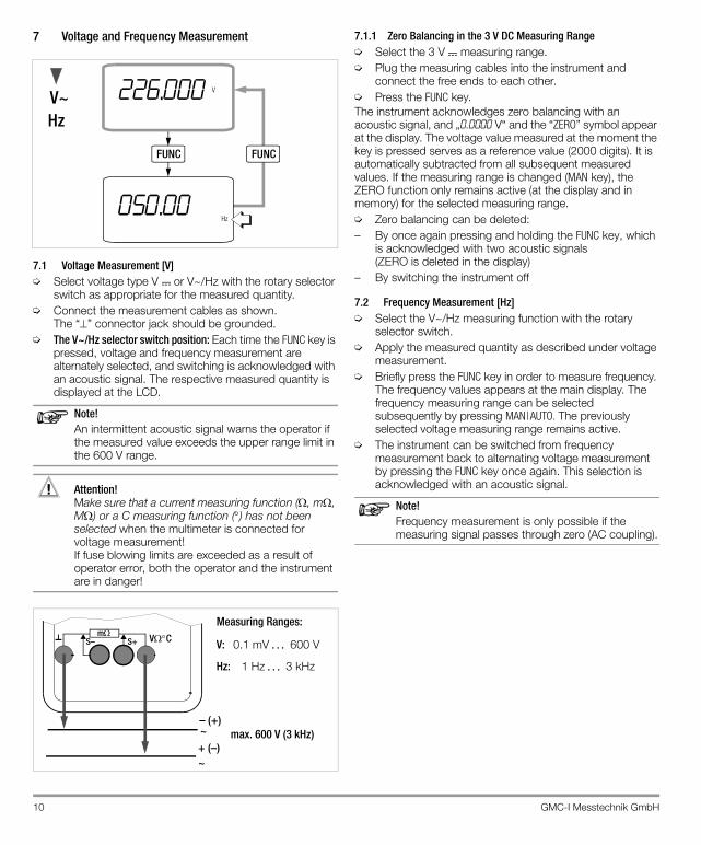
7 Voltage and Frequency Measurement
7.1 Voltage Measurement [V]➭ Select voltage type V or V~/Hz with the rotary selector
switch as appropriate for the measured quantity.➭ Connect the measurement cables as shown.
The “” connector jack should be grounded.➭ The V~/Hz selector switch position: Each time the FUNC key is
pressed, voltage and frequency measurement are alternately selected, and switching is acknowledged with an acoustic signal. The respective measured quantity is displayed at the LCD.
Note!An intermittent acoustic signal warns the operator if the measured value exceeds the upper range limit in the 600 V range.
Attention!!Make sure that a current measuring function (, m, M) or a C measuring function () has not been selected when the multimeter is connected for voltage measurement! If fuse blowing limits are exceeded as a result of operator error, both the operator and the instrument are in danger!
7.1.1 Zero Balancing in the 3 V DC Measuring Range➭ Select the 3 V measuring range.➭ Plug the measuring cables into the instrument and
connect the free ends to each other.➭ Press the FUNC key.The instrument acknowledges zero balancing with an acoustic signal, and „0.0000 V“ and the “ZERO” symbol appear at the display. The voltage value measured at the moment the key is pressed serves as a reference value (2000 digits). It is automatically subtracted from all subsequent measured values. If the measuring range is changed (MAN key), the ZERO function only remains active (at the display and in memory) for the selected measuring range.➭ Zero balancing can be deleted:– By once again pressing and holding the FUNC key, which
is acknowledged with two acoustic signals(ZERO is deleted in the display)
– By switching the instrument off
7.2 Frequency Measurement [Hz]➭ Select the V~/Hz measuring function with the rotary
selector switch.➭ Apply the measured quantity as described under voltage
measurement.➭ Briefly press the FUNC key in order to measure frequency.
The frequency values appears at the main display. The frequency measuring range can be selected subsequently by pressing MAN|AUTO. The previously selected voltage measuring range remains active.
➭ The instrument can be switched from frequency measurement back to alternating voltage measurement by pressing the FUNC key once again. This selection is acknowledged with an acoustic signal.
Note!Frequency measurement is only possible if the measuring signal passes through zero (AC coupling).
FUNC FUNC
V
Hz
V~Hz
226.000
050.00
mS+S– VC
– (+)~+ (–)~
max. 600 V (3 kHz)
V: 0.1 mV 600 V
Hz: 1 Hz 3 kHz
Measuring Ranges:
GMC-I Messtechnik GmbH 11
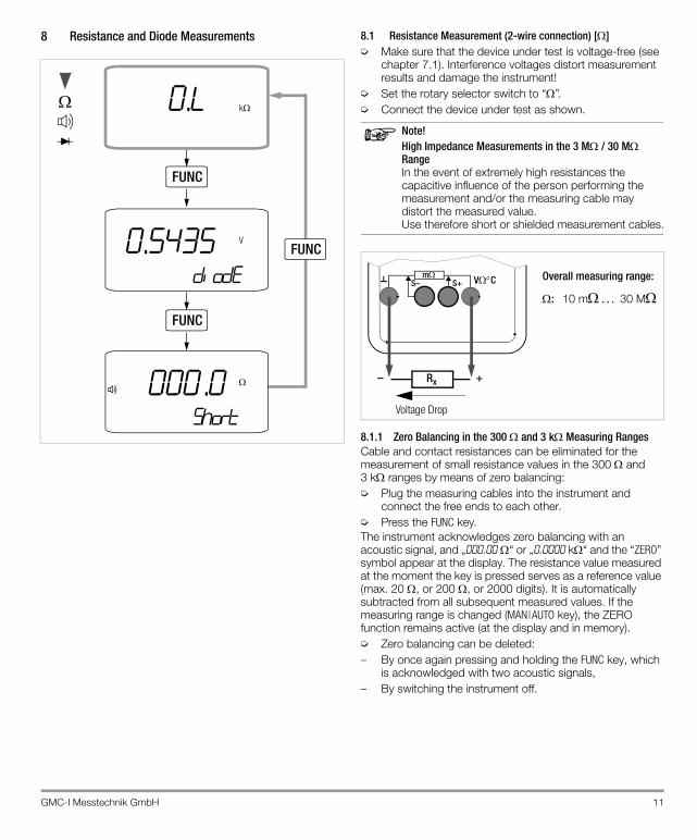
8 Resistance and Diode Measurements 8.1 Resistance Measurement (2-wire connection) []➭ Make sure that the device under test is voltage-free (see
chapter 7.1). Interference voltages distort measurement results and damage the instrument!
➭ Set the rotary selector switch to “”. ➭ Connect the device under test as shown.
Note!High Impedance Measurements in the 3 M/ 30 MRangeIn the event of extremely high resistances the capacitive influence of the person performing the measurement and/or the measuring cable may distort the measured value.Use therefore short or shielded measurement cables.
8.1.1 Zero Balancing in the 300 and 3 k Measuring RangesCable and contact resistances can be eliminated for the measurement of small resistance values in the 300 and 3 k ranges by means of zero balancing:➭ Plug the measuring cables into the instrument and
connect the free ends to each other.➭ Press the FUNC key.The instrument acknowledges zero balancing with an acoustic signal, and „000.00 “ or „0.0000 k“ and the “ZERO” symbol appear at the display. The resistance value measured at the moment the key is pressed serves as a reference value (max. 20 , or 200 , or 2000 digits). It is automatically subtracted from all subsequent measured values. If the measuring range is changed (MAN|AUTO key), the ZERO function remains active (at the display and in memory).➭ Zero balancing can be deleted:– By once again pressing and holding the FUNC key, which
is acknowledged with two acoustic signals,– By switching the instrument off.
0.L k
FUNC
0.5435diode
VFUNC
000. .0short
FUNC
mS+S– VC
Rx
Voltage Drop
: 10 m 30 M
Overall measuring range:
+–
12 GMC-I Messtechnik GmbH
8.2 Continuity Test during Resistance Measurement If the “acoustic signal ” function is activated and the 0 ... 310 measuring range is selected, a continuous acoustic signal is generated by the instrument within a range of 0 to approx. 10 .Overflow “0l” is displayed where Rd > 310 .
Activating and Deactivating Continuity Testing (acoustic signal)➭ Set the rotary selector switch to „/ / “.➭ Repeatedly press the FUNC key until and “short” appear
at the display, provided the connector jacks are open (Display 0.L).
➭ Connect the measurement cables to the device under test.
➭ The instrument is switched to resistance measurement by pressing the FUNC key once again.
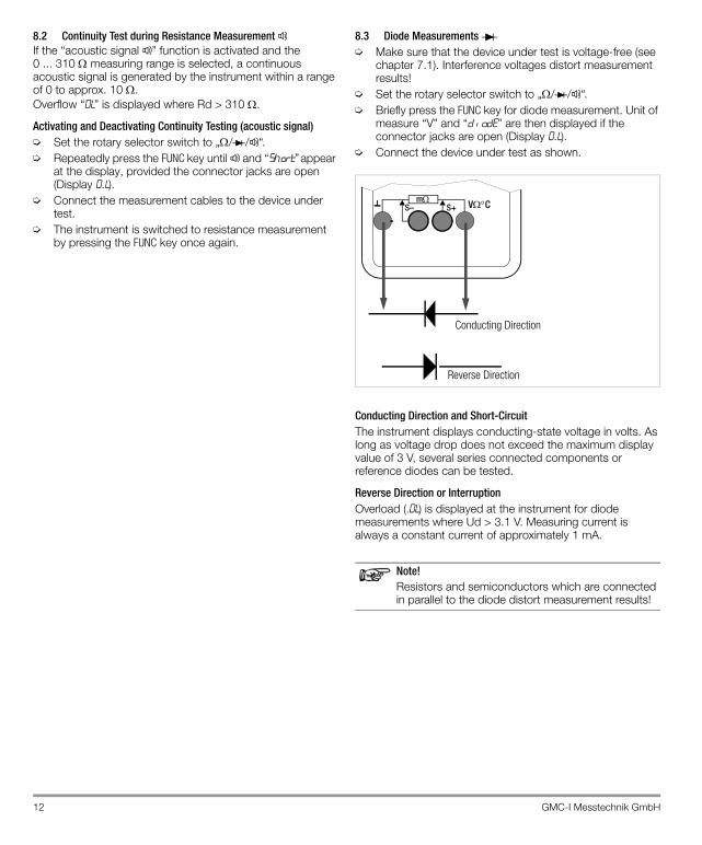
8.3 Diode Measurements ➭ Make sure that the device under test is voltage-free (see
chapter 7.1). Interference voltages distort measurement results!
➭ Set the rotary selector switch to „/ / “.➭ Briefly press the FUNC key for diode measurement. Unit of
measure “V” and “d iode” are then displayed if the connector jacks are open (Display 0.L).
➭ Connect the device under test as shown.
Conducting Direction and Short-CircuitThe instrument displays conducting-state voltage in volts. As long as voltage drop does not exceed the maximum display value of 3 V, several series connected components or reference diodes can be tested.
Reverse Direction or InterruptionOverload (.0l) is displayed at the instrument for diode measurements where Ud > 3.1 V. Measuring current is always a constant current of approximately 1 mA.
Note!Resistors and semiconductors which are connected in parallel to the diode distort measurement results!
mS+S– VC
Conducting Direction
Reverse Direction
GMC-I Messtechnik GmbH 13
9 Milliohm Measurement (4-Pole-Measurement)
9.1 Compensation of Cable ResistanceElectrical resistance is a dipole quantity which can generally only be measured using two poles. This is accomplished by directing a measuring current of predetermined magnitude through the device under test, and measuring the resultant voltage drop. The respective resistance value is derived from the quotient of these two values.The two points between which voltage is measured are decisive as regards the results of the measurement. All resistances between these two points add to the measured resistance value. These include contact resistance, as well as cable resistance. If a very low resistance value needs to be measured, for example contact resistance at a contactor with a value of only a few milliohms, the points between which voltage is measured must be moved out of the measuring instrument and positioned as closely as possible to the device under test. For this reason, the measuring instrument is equipped with separate jacks for current feed and voltage measurement. This type of 4-pole connection is known as connection according to Kelvin.KC4 Kelvin clips and KC27 Kelvin probes (available as accessories) allow for easy, correct connection.
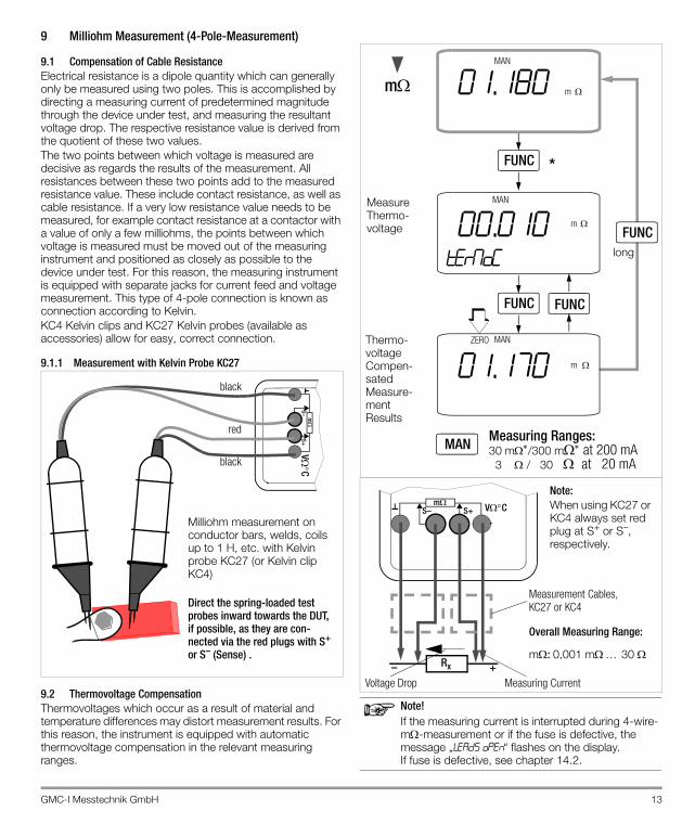
9.1.1 Measurement with Kelvin Probe KC27
9.2 Thermovoltage CompensationThermovoltages which occur as a result of material and temperature differences may distort measurement results. For this reason, the instrument is equipped with automatic thermovoltage compensation in the relevant measuring ranges.
Note!If the measuring current is interrupted during 4-wire-m-measurement or if the fuse is defective, the message „leads open“ flashes on the display. If fuse is defective, see chapter 14.2.
VC
m
S+S–
red
black
black
Milliohm measurement on conductor bars, welds, coils up to 1 H, etc. with Kelvin probe KC27 (or Kelvin clip KC4)
Direct the spring-loaded test probes inward towards the DUT, if possible, as they are con-nected via the red plugs with S+ or S– (Sense) .
01.180 m
FUNC
MAN
00.010termoC
mFUNC
01.170 m
FUNC
m
ZERO
MAN
MAN
Measure Thermo-voltage
Thermo-voltage Compen-sated Measure-ment Results
long
30 m/300 m at 200 mAMeasuring Ranges:MAN
FUNC
3 / 30 at 20 mA
*
mS+S– VC
Rx
Voltage Drop Measuring Current
m: 0,001 m 30
Overall Measuring Range:
+–
Measurement Cables,KC27 or KC4
Note:When using KC27 or KC4 always set red plug at S+ or S–, respectively.
14 GMC-I Messtechnik GmbH
9.3 Milliohm Measurement with 200 mA or 20 mA DC [m]➭ Make sure that the device under test is voltage-free (see
chapter 7.1). Interference voltages distort measurement results!
➭ Set the rotary selector switch to “m”.➭ Connect the device under test as shown.KC4 Kelvin clips and KC27 Kelvin probes (available as accessories) allow for easy, correct connection.Resistance at the current jacks should amount to < 1 .➭ If applicable, select the desired measuring range using
the MAN|AUTO key: 30 m, 300 m, 3 or 30 .This measuring method is suitable for resistances with inductances of up to 1 H.
Thermovoltage Correction in the 30/300 m Range➭ Press the FUNC key in order to measure thermovoltage.
Wait until the measured value has settled in. This may take several seconds, depending upon inductivity. Then press the FUNC key once again in order to return to the milliohm measuring function. All future measurement result will be corrected based upon the previously measured thermovoltage value. ZERO appears at the display in order to indicate active compensation.
Measurements at Inductive DevicesCoils in motors, choke ballasts and contactors are highly inductive. Changes in current at inductive devices, including switching the milliohmmeter on and off or changing the measuring range, result in a corresponding voltage change. These changes may be of significant magnitude, and may result in arcing under unfavorable conditions. The milliohmmeter is protected against arcing by means of suitable voltage arrestors.
9.4 Milliohm Measurement with 1 A Pulsating Measuring Current [m@1 A] (automatic thermovoltage correction in 3 300 m range)
➭ Make sure that the device under test is voltage-free (see chapter 7.1). Interference voltages distort measurement results!
➭ Set the rotary selector switch to “m@1A”.➭ Connect the device under test as shown.KC4 Kelvin clips and KC27 Kelvin probes (available as accessories) allow for easy, correct connection.Resistance at the current jacks should amount to < 0.2 .➭ If applicable, select the desired measuring range using
the MAN|AUTO key: 3 m, (30 m or 300 mThermovoltage is compensated automatically.
Note!Due to high current consumption during this measurement, NiMH storage batteries should be installed and the NA HIT 27 mains power battery charger should be used.
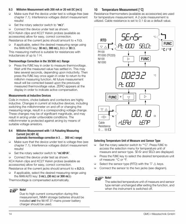
10 Temperature Measurement [C]Resistance thermometers (available as accessories) are used for temperature measurement. A 2-pole measurement is utilized. Cable resistance is set to 0.1 as a default value.
Selecting Temperature Unit of Measure and Sensor Type➭ Set the rotary selector switch to “C”. Press FUNC to
access the selection menu for temperature unit of measure and sensor type. sensr and selCt are displayed.
➭ Press the FUNC key to select the desired temperature unit of measure: C or F.
➭ Select the sensor type (RTD) with the keys. ➭ Connect the sensor to the two jacks (see diagram).
Note!The selected temperature unit of measure and sensor type remain unchanged after exiting the function, and when the instrument is switched off.
0023.2 C
sensrpt1000 selCt
C
Pt100
FUNC
FUNC
00.10temp
CableResistance
Pt1000 (TF220)Ni100Ni1000
0 50
+
pt1000
FUNC
RTD
C / F
rlead
GMC-I Messtechnik GmbH 15
Adjusting Cable Resistance➭ After selecting a resistance thermometer, the
measurement display is accessed by pressing the key.➭ The menu for cable resistance adjustment is opened by
simultaneously pressing the and keys. Rlead and temp are displayed.
➭ The decade (i.e. the position of the digit to be changed) is selected with the keys, and the respective digit is set with the keys.
➭ The menu is exited upon acknowledging the last digit by pressing the key, whereupon the measuring display returns. The cable resistance value remains in memory. The default value is 0.1 . Entry is limited to a range of 0 to 50 .
Note!The selected cable resistance value remains unchanged after exiting the function, and when the instrument is switched off.
11 Insulation Resistance Measurement [[email protected]] (METRA HIT 27I and METRA HIT H+E CAR only)
11.1 Preparing for Measurement
Note!High-resistance measurementsIn the event of extremely high resistances the capacitive influence of the person performing the measurement and/or the measuring cable may distort the measured value. Use therefore short or shielded measurement cables.The measurement cables may not come into contact with one another during high-resistance insulation measurements.
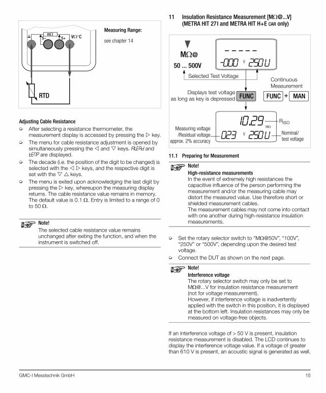
➭ Set the rotary selector switch to “M@50V”, “100V”, “250V” or “500V”, depending upon the desired test voltage.
➭ Connect the DUT as shown on the next page.
Note!Interference voltageThe rotary selector switch may only be set to [email protected] for insulation resistance measurement(not for voltage measurement).However, if interference voltage is inadvertently applied with the switch in this position, it is displayed at the bottom left. Insulation resistances may only be measured on voltage-free objects.
If an interference voltage of 50 V is present, insulation resistance measurement is disabled. The LCD continues to display the interference voltage value. If a voltage of greater than 610 V is present, an acoustic signal is generated as well.
mS+S– VC
RTD
see chapter 14
Measuring Range:
- - - - -V-000 250 V
M@
50 ... 500V
10.29V 023 250 V
M
Selected Test Voltage
Displays test voltageas long as key is depressed
RISO
FUNC MAN+FUNC
ContinuousMeasurement
Measuring voltage/Residual voltage
approx. 2% accuracy
Nominal/test voltage
16 GMC-I Messtechnik GmbH
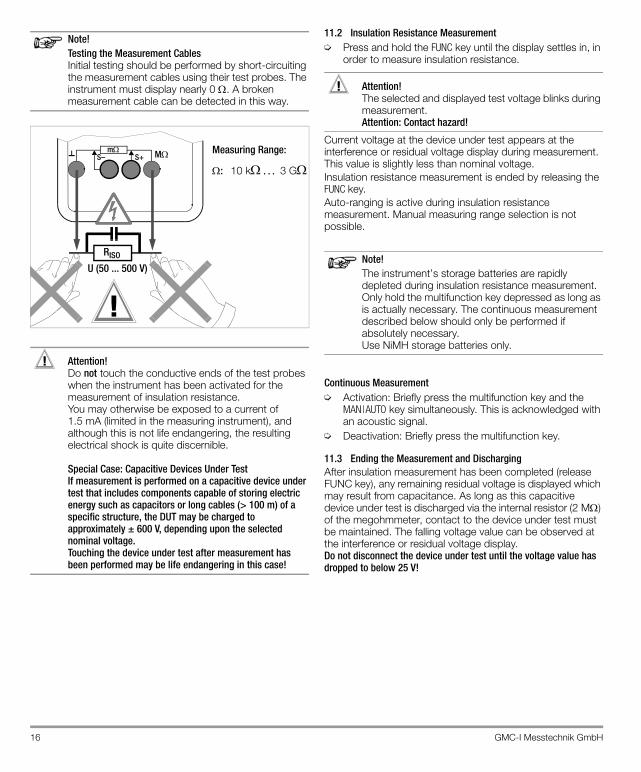
Note!Testing the Measurement Cables Initial testing should be performed by short-circuiting the measurement cables using their test probes. The instrument must display nearly 0 . A broken measurement cable can be detected in this way.
Attention!!Do not touch the conductive ends of the test probes when the instrument has been activated for the measurement of insulation resistance. You may otherwise be exposed to a current of 1.5 mA (limited in the measuring instrument), and although this is not life endangering, the resulting electrical shock is quite discernible.
Special Case: Capacitive Devices Under Test If measurement is performed on a capacitive device under test that includes components capable of storing electric energy such as capacitors or long cables (> 100 m) of a specific structure, the DUT may be charged to approximately ± 600 V, depending upon the selected nominal voltage. Touching the device under test after measurement has been performed may be life endangering in this case!
11.2 Insulation Resistance Measurement➭ Press and hold the FUNC key until the display settles in, in
order to measure insulation resistance.
Attention!!The selected and displayed test voltage blinks during measurement.Attention: Contact hazard!
Current voltage at the device under test appears at the interference or residual voltage display during measurement. This value is slightly less than nominal voltage.Insulation resistance measurement is ended by releasing the FUNC key.Auto-ranging is active during insulation resistance measurement. Manual measuring range selection is not possible.
Note!The instrument’s storage batteries are rapidly depleted during insulation resistance measurement. Only hold the multifunction key depressed as long as is actually necessary. The continuous measurement described below should only be performed if absolutely necessary. Use NiMH storage batteries only.
Continuous Measurement➭ Activation: Briefly press the multifunction key and the
MAN|AUTO key simultaneously. This is acknowledged with an acoustic signal.
➭ Deactivation: Briefly press the multifunction key.
11.3 Ending the Measurement and DischargingAfter insulation measurement has been completed (release FUNC key), any remaining residual voltage is displayed which may result from capacitance. As long as this capacitive device under test is discharged via the internal resistor (2 M) of the megohmmeter, contact to the device under test must be maintained. The falling voltage value can be observed at the interference or residual voltage display.Do not disconnect the device under test until the voltage value has dropped to below 25 V!
mS+S– M
RISO
: 10 k 3 G
Measuring Range:
!
U (50 ... 500 V)
GMC-I Messtechnik GmbH 17
12 Using the Menus – from the Initial InFO Menu to Operating and Measuring Parameters
Menu-driven operation via the initial „1NF0“ menu allows the user to query online help, activate the memory and query memory occupancy, activate the interface and configure device parameters.➭ The initial „1NF0“ menu is accessed by simultaneously
pressing and holding the FUNC and ON|OFF keys with the instrument switched on, until „1NF0“ appears at the display.
➭ The display can be switched from the main „1NF0“ menu to the other main menus including “store“, “memo”, “send” and “set”, and then back to the „1NF0“ menu, by repeatedly pressing the keys.
➭ After accessing the desired main menu, the associated submenus are opened by activating the key.
➭ The desired parameter or the desired function is selected by repeatedly pressing the keys.
➭ Acknowledge with the key in order to change the corresponding parameter or parameters.
➭ After the desired digit has been selected with the keys and the value has been adjusted with the keys, the next digit is accessed with the key, or the display is returned to the start menu or switched to the next submenu.
➭ The measuring mode is started by repeatedly pressing the FUNC key until the measuring display appears.
➭ The multimeter is switched off by pressing and holding the ON|OFF key until the display goes blank.
The following pages include an overview of the menu structure.
12.1 Sampling rAtEThe sampling rate specifies the time interval after which the respective measured value is transmitted to the interface or to measured value memory.Certain sampling rate limit values apply to various measured quantities, and these may not be exceeded (see table below).
12.2 Saving Measured ValuesThe METRA HIT27 provides two entirely different options for storing data:• Measured Value Memory – DATA Key Function:
Each time a measuring point is contacted, a measured value is stored in accordance with a defined condition (see chapter 5.1 and chapter 12.2.1).
• Memory Mode Operation – STORE Menu Function: After activating the STORE menu function, all measured values are saved in accordance with the selected sampling rate. Memory mode operation is ended manually using the same menu function.
In both cases, saved measured values can be read out with the help of METRAwin10 PC software (as of version 5.22). However, read-out is only possible if a USB-HIT IR adapter has been plugged into the METRA HIT27 and connected to the PC with an interface cable.
12.2.1 Memory Mode – DATA Key Function (see also chapter 5.1)The instrument is equipped with a measured value memory (32 kB) which is synchronized with a quartz movement, and has an average capacity of 1000 measured values. Minimum capacity is 800 measured values and maximum capacity is 1200 measured values.Data are stored and can be transmitted directly to a PC with the METRAwin10 software. Date and time must be reset if the storage batteries are depleted or the batteries or storage batteries are replaced.Measured values are stored in so-called blocks. Measured values resulting from the same measuring function are saved to the same block.Only absolute values and absolute time stamps can be saved, i.e. no relative or values, and no relative time stamps.Memory content can only be read out with the help of a PC, an IR adapter (USB-HIT), and METRAwin10 analysis software.Stored measurement data blocks are retained even if the instrument is without voltage supply.
Preparing for Memory Mode Operation➭ First set the sampling rate for memory mode operation,
and then start memory mode operation. The sampling rate can also be changed during memory mode operation.
➭ First select the desired measuring function and an appropriate measuring range.
➭ Check the storage battery charge level before starting long-term measurement recordings (see chapter 14.1 on page 25). Connect the mains power battery charger if applicable.
Measured Quantity Sampling Rate
V 0.5 s
V , 0.5 s
m , C (Pt100, Pt1000) 0.5 s
Hz 1 s
m@1A 1.5 s
18 GMC-I Messtechnik GmbH
12.2.2 Memory Mode Operation – STORE Menu Function➭ First set the sampling rate for memory mode operation,
and then start memory mode operation. The sampling rate can also be changed during memory mode operation.
➭ First select the desired measuring function and an appropriate measuring range.
➭ Check the storage battery charge level before starting long-term measurement recordings, see chapter 14.1 on page 25. Connect the charger if necessary.
Starting Memory Mode Operation with Menu Functions➭ Open the “Operating Mode” menu (refer to the menu
diagram) and select the StorE function.➭ Now activate the key to open the start menu for
memory mode operation: StArt blinks.Activate the key once again in order to start memory mode operation: REM appears at the display.
➭ Press the key in order to switch to the measuring function.
A new memory block is created when another measuring function is selected with the rotary switch or the FUNC key. Data storage then continues automatically. The “SLEEP MODE” is still active, i.e. the device is switched on and off automatically at sampling rates of long duration(see chapter 2).When memory capacity has been exhausted, MEMO FULL appears at the display, and an acoustic signal is generated simultaneously. The signal can be deactivated by pressing any key.
REM DisplayThe REM symbol indicates that memory mode operation has been activated via menu function STORE.Press the key if you wish to monitor the measured values also during the memory process.The „STORE“ function cannot be started while the „DATA“ function is activated.
Exiting Memory Mode Operation with Menu Functions➭ Select the StorE menu.➭ Activate the key: StOP blinks.➭ Activate the key once again: the auxiliary displays are
cleared. Memory mode operation has now been deactivated.
➭ Press the key in order to return to the measuring function.
➭ Memory mode operation can also be exited by switching the instrument off.
12.3 Querying Memory Occupancy – INFO MEMO/OCCUPMemory occupancy can be queried from the „1NF0“ menu. The main display shows current occupancy as a percentage between 001 and 100%
12.4 Clearing the Memory – MEMO CLEAr
Attention!!This function deletes all measured values from memory.
This function cannot be performed during memory mode;bUSYMEMO is displayed instead of CLEAR.
12.5 Activating the Default ValuesPreviously entered changes can be undone, and the default settings can be reactivated. This may be advisable after the occurrence of software or hardware errors.➭ Simultaneously press and hold the FUNC, MAN|AUTO and
DATA|CLEAR keys, and switch the instrument on with the ON|OFFkey.
GMC-I Messtechnik GmbH 19
12.6 Transmission Mode Operation with RS 232 InterfaceThe METRA HIT27 is equipped with an bidirectional infrared interface for the transmission of measurement data to a PC. Data are transferred optically through the instrument housing by means of infrared light to an interface adapter (accessory USB-HIT), which is attached to the instrument. The adapter’s USB-HIT-interface allows for the establishment of a connection to the PC via an interface cable. The driver to be installed assigns a virtual COM interface to the instrument. It is not possible to set up a multi-channel system with this adapter.Beyond this, commands and parameters can be transmitted from the PC to the instrument as well. The following functions can be executed:• Configuration and read-out of measuring parameters• Measuring function and measuring range selection• Start measurements• Read out measured values
Activating the InterfaceThe interface is switched on manually as described below for transmission mode operation. The instrument continuously transmits measurement data to the PC via the interface adapter in this operating mode. The interface is activated automatically by the PC for receiving operation (i.e. the instrument receives data from the PC).
Starting Transmission with Menu FunctionsInFO SEnd StArt
The symbol blinks at the display in order to indicate interface operation.
Automatic Activation and Deactivation of the Transmission ModeIf the sampling rate is 20 s or longer, the display is switched off automatically between samples in order to prolong storage battery or battery service life.Exception: continuous operationAs soon as an event occurs, the display is automatically switched back on.
Configuring Interface Parameters
Addr – AddressIf several instruments are connected to the PC via interface adapters, an unique address must be assigned to each device. Address 1 should be used for the first device, address 2 for the second etc. If only one multimeter is utilized, an address between 1 and 14 should be used. Address 15 is not used for addressing, i.e. the device with address 15 always responds, regardless of the actual address.
20 GMC-I Messtechnik GmbH
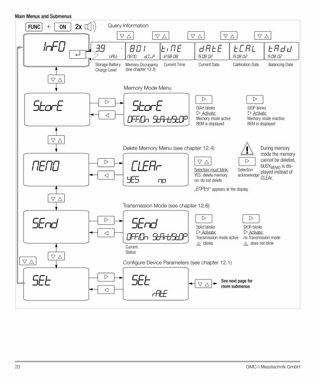
Main Menus and Submenus
1nf0
mem0
send
Set
2xFUNC ON
Clearyes no
Selection must blink:YES: delete memoryno: do not delete
Selection acknowledge
send0ff/0n start/st0p
StArt blinksActivate:Transmission mode active
StOP blinksActivate:no Transmission mode
Current Status
3.9batt
V 8 01mem0 oCCUp
t im e12:58 :08
d a t e15 08 . 02
setrate
See next page for more submenus
Storage BatteryCharge Level
Current Time Current Date
Delete Memory Menu (see chapter 12.4)
Transmission Mode (see chapter 12.6)
Configure Device Parameters (see chapter 12.1)
Query Information
!
Memory Occupancy(see chapter 12.3)
t C a l15 08 . 02
Calibration Date
t a d J15 08 . 02
Balancing Date
blinks does not blink
„EMPTY “ appears at the display
store store0ff/0n start/st0p
Memory Mode Menu
StArt blinksActivate:Memory mode active
StOP blinksActivate:Memory mode inactive
REM is displayed REM is displayed
During memory mode the memory cannot be deleted, bUSYMEMO is dis-played instead of CLEAr.
GMC-I Messtechnik GmbH 21
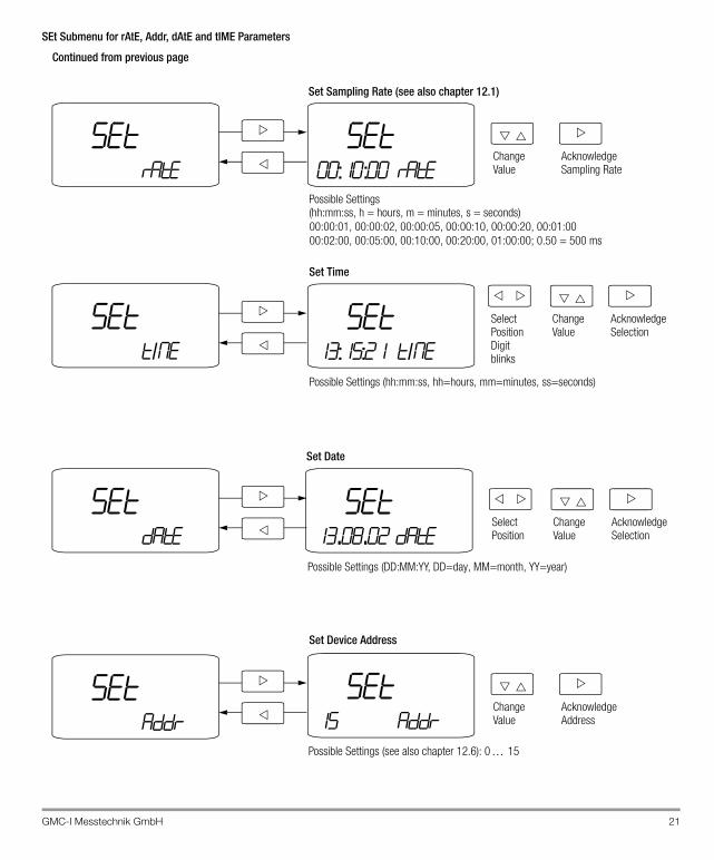
SEt Submenu for rAtE, Addr, dAtE and tIME Parameters
setrate
setaddr
settIme
set00:10:00 rate
Change Value
Acknowledge Sampling Rate
00:00:01, 00:00:02, 00:00:05, 00:00:10, 00:00:20, 00:01:0000:02:00, 00:05:00, 00:10:00, 00:20:00, 01:00:00; 0.50 = 500 ms
Possible Settings
set15 addr
Change Value
Set Device Address
AcknowledgeAddress
set13:15:21 tIme
Change Value
Set Time
Acknowledge Selection
set13.08.02 date
Set Date
SelectPosition
Change Value
Acknowledge Selection
SelectPosition
Possible Settings (DD:MM:YY, DD=day, MM=month, YY=year)
Possible Settings (hh:mm:ss, hh=hours, mm=minutes, ss=seconds)
Digitblinks
Possible Settings (see also chapter 12.6): 0 15
Set Sampling Rate (see also chapter 12.1)
(hh:mm:ss, h = hours, m = minutes, s = seconds)
Continued from previous page
setdate
22 GMC-I Messtechnik GmbH
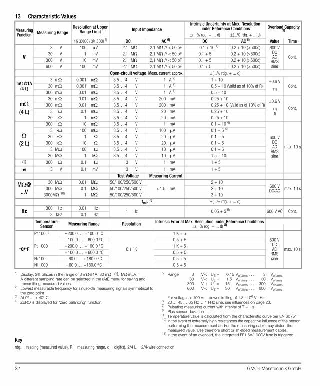
13 Characteristic Values
1) Display: 3¾ places in the range of 3 m@1A, 30 m, , [email protected]; A different sampling rate can be selected in the rAtE menu for saving and transmitting measured values.
2) Lowest measurable frequency for sinusoidal measuring signals symmetrical to the zero point
3) At 0 + 40C4) ZERO is displayed for “zero balancing” function.
5) Range 3 V~: UE = 0.15 Veff/rms . . . 3 Veff/rms30 V~: UE = 1.5 Veff/rms . . . 30 Veff/rms
300 V~: UE = 15 Veff/rms . . . 300 Veff/rms600 V~: UE = 30 Veff/rms . . . 600 Veff/rms
For voltages > 100 V: power limiting of 1.8 · 106 V · Hz6) 20 45 65 Hz 1 kHz sine, see influences on page 23.7) Pulsating measuring current with interval of T = 1 s8) Plus sensor deviation9) Temperature value is calculated from the characteristic curve per EN 6075110) In the event of extremely high resistances the capacitive influence of the person
performing the measurement and/or the measuring cable may distort the measured value. Use therefore short or shielded measurement cables.
11) In the event of an overload, the integrated FF1.6A/1000V fuse is triggered.Keyrdg. = reading (measured value), R = measuring range, d = digit(s), 2/4 L = 2/4-wire connection
MeasuringFunction Measuring Range
Resolution at Upper Range Limit Input Impedance
Intrinsic Uncertainty at Max. Resolutionunder Reference Conditions Overload Capacity
3)(...% rdg. + ... d) (...% rdg. + ... d)
4¾ 30000 / 3¾ 3000 1) DC AC 6) DC AC
6) Value Time
V
3 V 100 V 2.1 M 2.1 M // < 50 pF 0.1 + 10 4) 0.2 + 10 (>500d) 600 VDCAC
RMSsine
Cont.30 V 1 mV 2.1 M 2.1 M // < 50 pF 0.1 + 5 0.2 + 10 (>500d)
300 V 10 mV 2.1 M 2.1 M // < 50 pF 0.1 + 5 0.2 + 10 (>500d)600 V 100 mV 2.1 M 2.1 M // < 50 pF 0.1 + 5 0.2 + 10 (>500d)
Open-circuit voltage Meas. current approx. (...% rdg. + ... d)
m@1A(4 L)
3 m 0.001 m 3.5 4 V 1 A 7) 1 + 10 0.6 V
11)Cont.30 m 0.001 m 3.5 4 V 1 A 7) 0.5 + 10 (Valid as of 10% of R)
300 m 0.01 m 3.5 4 V 1 A 7) 0.5 + 10
m(4 L)
30 m 0.01 m 3.5 4 V 200 mA 0.25 + 10 0.6 V
11)4)
Cont.300 m 0.01 m 3.5 4 V 200 mA 0.25 + 10 (Valid as of 10% of R)
3 0.1 m 3.5 4 V 20 mA 0.25 + 1030 1 m 3.5 4 V 20 mA 0.25 + 10
(2 L)
300 10 m 3.5 4 V 1 mA 0.1 + 10 4)
600 VDCAC
RMSsine
max. 10 s
3 k 100 m 3.5 4 V 100 A 0.1 + 5 4)
30 k 1 3.5 4 V 20 A 0.1 + 5 300 k 10 3.5 4 V 20 A 0.1 + 5
3 M 100 3.5 4 V 10 A 0.1 + 5 30 M 1 k 3.5 4 V 10 A 1.5 + 10
300 0.1 3 V 1 mA 1 + 5
3 V 0.1 mV 3 V 1 mA 1 + 5Test Voltage Measuring Current
30 M 0.01 M 50/100/250/500 V< 1.5 mA
2 + 10600 VDC/AC max. 10 s300 M 0.1 M 50/100/250/500 V 2 + 10
3000M 10) 1 M 50/100/250/500 V 3 + 10fmin 2) (...% rdg. + ... d)
Hz300 Hz 0.01 Hz
1 Hz 0.05 + 5 5) 600 V AC Cont.3 kHz 0.1 Hz
Temperature Sensor Measuring Range Resolution Intrinsic Error at Max. Resolution under Reference Conditions
(...% rdg. + ... d) 8)
C/F
Pt 100 9) –200.0 +100.0 C
0.1 K
1 K + 5600 V
DCAC
RMSsine
max. 10 s
+100.0 +600.0 C 0.5 + 5Pt 1000 –200.0 +100.0 C 1 K + 5
+100.0 +600.0 C 0.5 + 5Ni 100 –60.0 +180.0 C 0.5 + 5Ni 1000 –60.0 +180.0 C 0.5 + 5
GMC-I Messtechnik GmbH 23
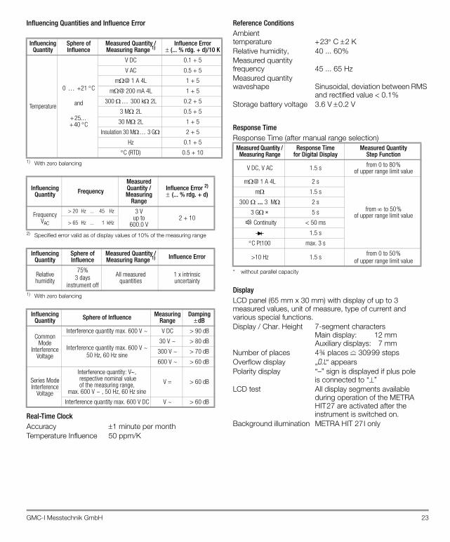
Influencing Quantities and Influence Error
1) With zero balancing
2) Specified error valid as of display values of 10% of the measuring range
1) With zero balancing
Real-Time ClockAccuracy 1 minute per monthTemperature Influence 50 ppm/K
Reference ConditionsAmbienttemperature +23C 2 KRelative humidity, 40 ... 60%Measured quantityfrequency 45 ... 65 HzMeasured quantitywaveshape Sinusoidal, deviation between RMS
and rectified value < 0.1%Storage battery voltage 3.6 V0.2 V
Response TimeResponse Time (after manual range selection)
* without parallel capacity
DisplayLCD panel (65 mm x 30 mm) with display of up to 3 measured values, unit of measure, type of current and various special functions.Display / Char. Height 7-segment characters
Main display: 12 mmAuxiliary displays: 7 mm
Number of places 4¾ places 30999 stepsOverflow display „0. L“ appearsPolarity display “–” sign is displayed if plus pole
is connected to “”LCD test All display segments available
during operation of the METRA HIT27 are activated after the instrument is switched on.
Background illumination METRA HIT 27I only
Influencing Quantity
Sphere of Influence
Measured Quantity /Measuring Range 1)
Influence Error (... % rdg. + d)/10 K
Temperature
0 +21 C
and
+25 +40 C
V DC 0.1 + 5
V AC 0.5 + 5
m@ 1 A 4L 1 + 5
m@ 200 mA 4L 1 + 5
300 300 k 2L 0.2 + 5
3 M2L 0.5 + 5
30 M2L 1 + 5
Insulation 30 M 3 G 2 + 5
Hz 0.1 + 5
C (RTD) 0.5 + 10
Influencing Quantity Frequency
Measured Quantity /Measuring
Range
Influence Error 2) (... % rdg. + d)
FrequencyVAC
> 20 Hz ... 45 Hz 3 Vup to
600.0 V2 + 10
> 65 Hz ... 1 kHz
Influencing Quantity
Sphere of Influence
Measured Quantity /Measuring Range 1) Influence Error
Relative humidity
75%3 days
instrument off
All measured quantities
1 x intrinsic uncertainty
Influencing Quantity Sphere of Influence Measuring
RangeDampingdB
Common Mode
Interference Voltage
Interference quantity max. 600 V ~ V DC > 90 dB
Interference quantity max. 600 V ~50 Hz, 60 Hz sine
30 V ~ > 80 dB
300 V ~ > 70 dB
600 V ~ > 60 dB
Series ModeInterference
Voltage
Interference quantity: V, respective nominal value of the measuring range,
max. 600 V ~ , 50 Hz, 60 Hz sine
V = > 60 dB
Interference quantity max. 600 V DC V ~ > 60 dB
Measured Quantity / Measuring Range
Response Timefor Digital Display
Measured QuantityStep Function
V DC, V AC 1.5 s from 0 to 80% of upper range limit value
m@ 1 A 4L 2 s
from to 50% of upper range limit value
m 1.5 s
300 ... 3 M 2 s
3 G 5 s
Continuity < 50 ms
1.5 s
C Pt100 max. 3 s
>10 Hz 1.5 s from 0 to 50% of upper range limit value
24 GMC-I Messtechnik GmbH
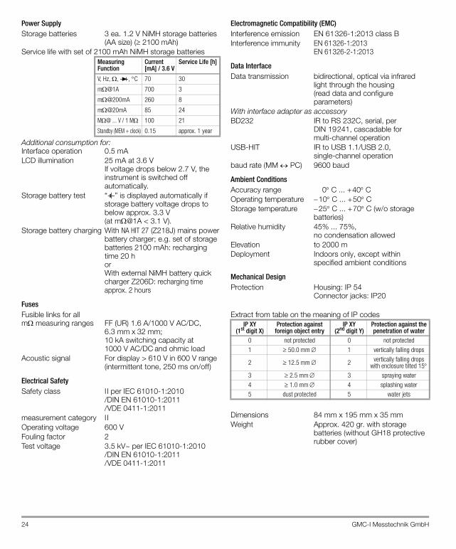
Power SupplyStorage batteries 3 ea. 1.2 V NiMH storage batteries
(AA size) ( 2100 mAh)Service life with set of 2100 mAh NiMH storage batteries
Additional consumption for: Interface operation 0.5 mALCD illumination 25 mA at 3.6 V
If voltage drops below 2.7 V, the instrument is switched off automatically.
Storage battery test “ ” is displayed automatically if storage battery voltage drops to below approx. 3.3 V (at m@1A < 3.1 V).
Storage battery charging With NA HIT 27 (Z218J) mains powerbattery charger; e.g. set of storage batteries 2100 mAh: recharging time 20 horWith external NiMH battery quick charger Z206D: recharging time approx. 2 hours
FusesFusible links for all m measuring ranges FF (UR) 1.6 A/1000 V AC/DC,
6.3 mmx32 mm;10 kA switching capacity at 1000 V AC/DC and ohmic load
Acoustic signal For display > 610 V in 600 V range (intermittent tone, 250 ms on/off)
Electrical SafetySafety class I I per IEC 61010-1:2010
/DIN EN 61010-1:2011 /VDE 0411-1:2011
measurement category I IOperating voltage 600 VFouling factor 2Test voltage 3.5 kV~ per IEC 61010-1:2010
/DIN EN 61010-1:2011 /VDE 0411-1:2011
Electromagnetic Compatibility (EMC)Interference emission EN 61326-1:2013 class BInterference immunity EN 61326-1:2013
EN 61326-2-1:2013
Data InterfaceData transmission bidirectional, optical via infrared
light through the housing(read data and configure parameters)
With interface adapter as accessoryBD232 IR to RS 232C, serial, per
DIN 19241, cascadable formulti-channel operation
USB-HIT IR to USB 1.1/USB 2.0, single-channel operation
baud rate (MM PC) 9600 baud
Ambient ConditionsAccuracy range 0C ... +40COperating temperature 10C ... +50CStorage temperature 25C ... +70C (w/o storage
batteries)Relative humidity 45% ... 75%,
no condensation allowedElevation to 2000 mDeployment Indoors only, except within
specified ambient conditions
Mechanical DesignProtection Housing: IP 54
Connector jacks: IP20
Extract from table on the meaning of IP codes
Dimensions 84 mm x 195 mm x 35 mmWeight Approx. 420 gr. with storage
batteries (without GH18 protective rubber cover)
Measuring Function
Current [mA] / 3.6 V
Service Life [h]
V, Hz, , , C 70 30
m@1A 700 3
m@200mA 260 8
m@20mA 85 24
M@ ... V / 1 M 100 21
Standby (MEM + clock) 0.15 approx. 1 year
IP XY (1st digit X)
Protection againstforeign object entry
IP XY (2nd digit Y)
Protection against the penetration of water
0 not protected 0 not protected1 50.0 mm 1 vertically falling drops
2 12.5 mm 2 vertically falling drops with enclosure tilted 15
3 2.5 mm 3 spraying water4 1.0 mm 4 splashing water5 dust protected 5 water jets
GMC-I Messtechnik GmbH 25
14 Maintenance
Attention!!Disconnect the instrument from the measuring circuit before opening to replace storage batteries, batteries or fuses!
14.1 Storage Batteries and Batteries
Warning!
The mains power battery charger may not be connected if normal batteries have been installed instead of storage batteries: Danger of explosion!
Removing the Storage Batteries During Periods of Non-UseThe integrated quartz clock draws power from the storage batteries, even when the instrument is switched off. It is advisable to remove the storage batteries during long periods of non-use for this reason (e.g. vacation). This prevents excessive depletion of the storage batteries, which may result in damage under unfavorable conditions.
Checking Storage Battery Charge-Level and ConditionThe current storage battery charge level can be queried in the “Info” menu (see chapter 12 on page 17): FUNC + ON|OFF InF0 X.X V (bAtt).Make sure that no storage battery leakage has occurred before initial start-up, and after long periods of storage. Continue to inspect the storage batteries for leakage at short, regular intervals.– If storage battery leakage has occurred, carefully and
completely clean electrolyte from the instrument with a damp cloth, and replace the storage batteries before using the instrument.
– If the “ ” symbol appears at the display, the storage batteries should be replaced or recharged as soon as possible. You can continue working with the instrument, but reduced measuring accuracy may result. Depleted storage batteries require approximately 20 hours recharging time with the NA HIT 27 mains power battery charger. Recharging starts as soon as the instrument is connected to the mains power battery charger. If the storage batteries have been excessively depleted, the instrument cannot be switched on. If this is the case, leave the (switched on) instrument connected to the charger for approximately 30 minutes, and then proceed as described above.
Attention!!Storage battery or battery leakage must be avoided. Resulting damage is not covered by the guarantee.
Recharging the Storage BatteriesUse only the NA HIT 27 mains power battery charger (article number Z218J) from GMC-I Messtechnik GmbH to recharge the storage batteries in the instrument. This assures operator safety by means of an extremely well insulated cable, and safe electrical isolation (nominal secondary ratings: 5 V/600 mA). The recharging time of the batteries (2,100 mAh) in the instrument is approx. 20 h.
Before connecting the mains power battery charger to the recharging jack, make sure that: – Storage batteries have been installed (not normal batteries) – The instrument has been disconnected from the measuring
circuit at all poles.If possible, use the mains power battery charger only for recharging storage batteries, not for measurements, in order to avoid influence errors.
Replacing the Storage Batteries➭ Set the instrument face down onto a flat working surface,
loosen the two screws at the back and lift off the housing base, starting at the bottom. The housing top and housing base are held together with the help of snap hooks at the top front.
➭ Remove the storage batteries from the battery compartment.
➭ Insert three 1.2 V NiMH storage batteries into the battery compartment, making sure that the plus and minus poles match up with the provided polarity symbols.
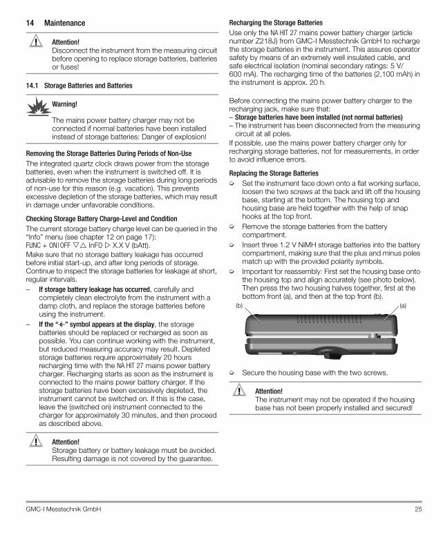
➭ Important for reassembly: First set the housing base onto the housing top and align accurately (see photo below). Then press the two housing halves together, first at the bottom front (a), and then at the top front (b).
➭ Secure the housing base with the two screws.
Attention!!The instrument may not be operated if the housing base has not been properly installed and secured!
(b) (a)
26 GMC-I Messtechnik GmbH
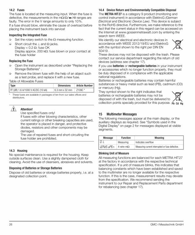
14.2 FusesThe fuse is located at the measuring input. When the fuse is defective, the measurements in the m// / ranges are faulty. The error in the V range amounts to only 10%.If a fuse should blow, eliminate the cause of overload before placing the instrument back into service!
Inspecting the Integrated Fuse➭ Set the rotary switch to the measuring function.➭ Short circuit the and jacks.
Display < 0.2 : fuse OKDisplay approx. 200 k:fuse blown or poor contact at the fuse holder
Replacing the Fuse➭ Open the instrument as described under “Replacing the
Storage Batteries” .➭ Remove the blown fuse with the help of an abject such
as a test probe, and replace it with a new fuse.Table of Allowable Fuses
* These fuses are available in packages of ten from our sales offices and distributors.
Attention!!Use specified fuses only! If fuses with other blowing characteristics, other current ratings or other breaking capacities are used, the operator is placed in danger, and protective diodes, resistors and other components may be damaged. The use of repaired fuses and short-circuiting the fuse holder are prohibited.
14.3 HousingNo special maintenance is required for the housing. Keep outside surfaces clean. Use a slightly dampened cloth for cleaning. Avoid the use of cleansers, abrasives and solvents.
Disposing of Batteries or Storage BatteriesDispose of old batteries or storage batteries properly, i.e. at a designated collection point.
14.4 Device Return and Environmentally Compatible DisposalThe METRA HIT27 is a category 9 product (monitoring and control instrument) in accordance with ElektroG (German Electrical and Electronic Device Law). This device is subject to the RoHS directive. Furthermore, we make reference to the fact that the current status in this regard can be accessed on the Internet at www.gossenmetrawatt.com by entering the search term WEEE.We identify our electrical and electronic devices in accordance with WEEE 2012/19/EU and ElektroG with the symbol shown to the right per DIN EN 50419 .These devices may not be disposed with the trash. Please contact our service department regarding the return of old devices (address see chapter 17).If you use batteries or rechargeable batteries in your instrument or accessories which no longer function properly, they must be duly disposed of in compliance with the applicable national regulations.Batteries or rechargeable batteries may contain harmful substances or heavy metal such as lead (PB), cadmium (CD) or mercury (Hg).They symbol shown to the right indicates that batteries or rechargeable batteries may not be disposed of with the trash, but must be delivered to collection points specially provided for this purpose.
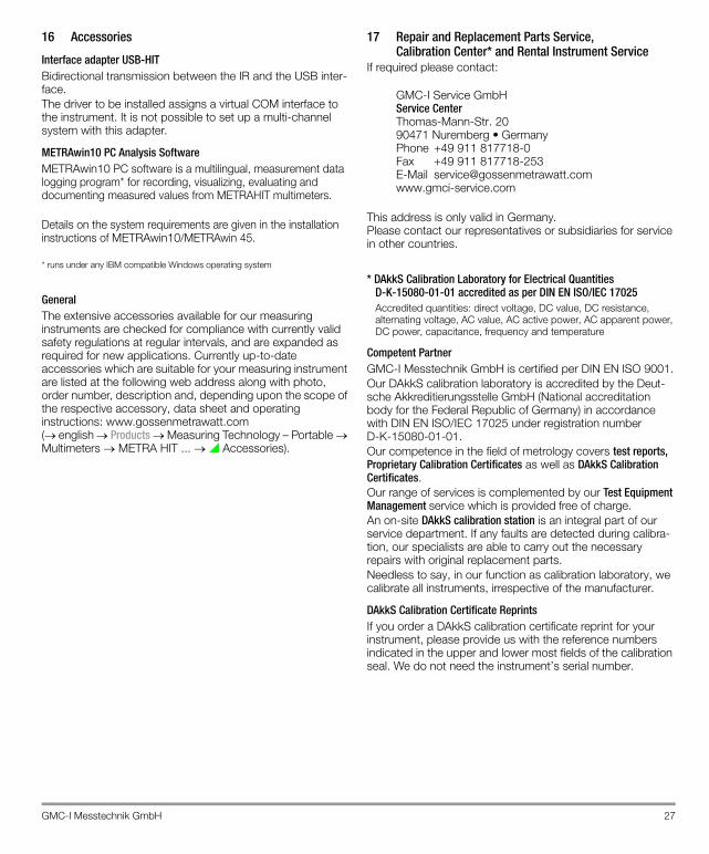
15 Multimeter MessagesThe following messages appear at the main display, or the auxiliary displays as required. See “Symbols used in the Digital Display” on page 2 for messages displayed at visible segments.
Blinking Unit of MeasureAll measuring functions are balanced for each METRA HIT27 at the factory in accordance with the respective technical specification. If a unit of measure blinks, this indicates that balancing constants which have been established and saved to the multimeter are no longer available for the respective function. If this is the case, measurement results may deviate from the specification. We recommend sending the instrument to our Repair and Replacement Parts department for rebalancing (see chapter 17).
Type Dimensions Article Number
FF (UR) 1.6 A/1000 V AC/DC (10 kA) 6.3 mm x 32 mm Z109C *
Message Function Meaning0. L Measuring Indicates overflow
leads open 4-wire-m Measuring current interrupted or fuse defective.
Pb Cd Hg
GMC-I Messtechnik GmbH 27
16 Accessories
Interface adapter USB-HIT Bidirectional transmission between the IR and the USB inter-face.The driver to be installed assigns a virtual COM interface to the instrument. It is not possible to set up a multi-channel system with this adapter.
METRAwin10 PC Analysis SoftwareMETRAwin10 PC software is a multilingual, measurement data logging program* for recording, visualizing, evaluating and documenting measured values from METRAHIT multimeters.
Details on the system requirements are given in the installation instructions of METRAwin10/METRAwin 45.
* runs under any IBM compatible Windows operating system
GeneralThe extensive accessories available for our measuring instruments are checked for compliance with currently valid safety regulations at regular intervals, and are expanded as required for new applications. Currently up-to-date accessories which are suitable for your measuring instrument are listed at the following web address along with photo, order number, description and, depending upon the scope of the respective accessory, data sheet and operating instructions: www.gossenmetrawatt.com (english Products Measuring Technology – Portable Multimeters METRA HIT ... Accessories).
17 Repair and Replacement Parts Service,Calibration Center* and Rental Instrument Service
If required please contact:
GMC-I Service GmbHService Center Thomas-Mann-Str. 2090471 Nuremberg • Germany Phone +49 911 817718-0Fax +49 911 817718-253E-Mail [email protected]
This address is only valid in Germany.Please contact our representatives or subsidiaries for service in other countries.
* DAkkS Calibration Laboratory for Electrical Quantities D-K-15080-01-01 accredited as per DIN EN ISO/IEC 17025Accredited quantities: direct voltage, DC value, DC resistance, alternating voltage, AC value, AC active power, AC apparent power, DC power, capacitance, frequency and temperature
Competent PartnerGMC-I Messtechnik GmbH is certified per DIN EN ISO 9001.Our DAkkS calibration laboratory is accredited by the Deut-sche Akkreditierungsstelle GmbH (National accreditation body for the Federal Republic of Germany) in accordance with DIN EN ISO/IEC 17025 under registration number D-K-15080-01-01. Our competence in the field of metrology covers test reports, Proprietary Calibration Certificates as well as DAkkS Calibration Certificates.Our range of services is complemented by our Test Equipment Management service which is provided free of charge.An on-site DAkkS calibration station is an integral part of our service department. If any faults are detected during calibra-tion, our specialists are able to carry out the necessary repairs with original replacement parts.Needless to say, in our function as calibration laboratory, we calibrate all instruments, irrespective of the manufacturer.
DAkkS Calibration Certificate ReprintsIf you order a DAkkS calibration certificate reprint for your instrument, please provide us with the reference numbers indicated in the upper and lower most fields of the calibration seal. We do not need the instrument’s serial number.
Edited in Germany • Subject to change without notice • A pdf version is available on the internet.
GMC-I Messtechnik GmbHSüdwestpark 1590449 Nürnberg• Germany
Phone +49 911 8602-111Fax +49 911 8602-777E-Mail [email protected]
18 GuaranteeThe guarantee period for all METRA HIT measuring and calibration instruments is 3 years after date of shipment.Calibration is guaranteed for a period of 12 months. The guarantee covers materials and workmanship. Damages resulting from use for any other than the intended purpose or operating errors, as well as any and all consequential damages, are excluded.
19 Product SupportIf required please contact:
GMC-I Messtechnik GmbHProduct Support HotlinePhone +49 911 8602-0Fax +49 911 8602 709E-Mail [email protected]
20 RecalibrationThe respective measuring task and the stress to which your measuring instrument is subjected affect the ageing of the components and may result in deviations from the guaranteed accuracy.
If high measuring accuracy is required and the instrument is frequently used in field applications, combined with transport stress and great temperature fluctuations, we recommend a relatively short calibration interval of 1 year. If your measuring instrument is mainly used in the laboratory and indoors without being exposed to any major climatic or mechanical stress, a calibration interval of 2-3 years is usually sufficient.
During recalibration* in an accredited calibration laboratory(DIN EN ISO/IEC 17025) the deviations of your instrument in relation to traceable standards are measured and documented. The deviations determined in the process are used for correction of the readings during subsequent application.
We are pleased to perform DAkkS or factory calibrations for you in our calibration laboratory. Please visit our website at www.gossenmetrawatt.com ( Company DAkkS Calibration Center or FAQs Calibration questions and answers).
By having your measuring instrument calibrated regularly, you fulfill the requirements of a quality management system per DIN EN ISO 9001.
* Verification of specifications or adjustment services are not part of the calibration. For products from our factory, however, any necessary adjustment is frequently performed and the observance of the relevant specification is confirmed.