Embed Size (px)
Citation preview

Methods for the specification and verification of business processes
MPB (6 cfu, 295AA)
Roberto Brunihttp://www.di.unipi.it/~bruni
22 - Business process execution language
1
martedì 10 dicembre 13

Object
2
We overview the key features of BPEL
martedì 10 dicembre 13

3
martedì 10 dicembre 13

BPEL
4
martedì 10 dicembre 13

Business process execution language
5
Also known as:Web Services Business Process Execution Language
(WS-BPEL) Business Process Execution Language for Web Services
(BPEL4WS)
it is a standard executable language for orchestrating the use of Web Service within business processes
it deals with import / export information, remote invocation, correlation, fault handling, compensation
martedì 10 dicembre 13

Web services
6
Web services fix a standard for interoperability between heterogeneous, loosely coupled, remote
software applications(separately developed, running on different platforms)
over (not only) the HTTP protocol
Informally:web services are for softwarewhat web sites are for human
martedì 10 dicembre 13

WS basics
7
Services must be made available on the web(need a server)
Services must be advertised over the web(need some repositories)
Service repositories must be queried(need service description)
Services must be invoked(need standard communication format)
martedì 10 dicembre 13

XMLification
8
Network
XML based messaging
Service description
Service publication
Service discovery
Service composition
HTTP, HTTPS, SMTP
SOAP
WSDL
UDDI
WSFL, BPEL, ...
{
martedì 10 dicembre 13

WS-*
9
martedì 10 dicembre 13

10
Web Services Standards Overview
innoQ Deutschland GmbH innoQ Schweiz GmbHHalskestraße 17 Gewerbestrasse 11D-40880 Ratingen CH-6330 ChamPhone +49 21 02 77 162-100 Phone +41 41 743 [email protected] · www.innoq.com
This
post
er is
not
to b
e re
prod
uced
or t
rans
mitt
ed in
any
form
or f
or a
ny p
urpo
se w
ithou
t the
exp
ress
per
miss
ion
of in
noQ
Deut
schl
and
GmbH
.·Co
pyrig
ht ©
inno
Q De
utsc
hlan
d Gm
bH. A
ll Ri
ghts
Res
erve
d. T
he p
oste
r may
also
con
tain
refe
renc
es to
oth
er c
ompa
ny, o
rgan
isatio
n, b
rand
and
pro
duct
nam
es. T
hese
com
pany
, org
anisa
tion,
bra
nd a
nd p
rodu
ct n
ames
are
use
d he
rein
for i
dent
ifica
tion
purp
oses
onl
y an
d m
ay b
e th
e tr
adem
arks
of t
heir
resp
ectiv
e ow
ners
.
InteroperabilityIssues
Metadata Specifications Reliability Specifications
Security Specifications TransactionSpecifications
Messaging Specifications SOAP
Management Specifications PresentationSpecifications
Messaging Specifications
WS-Notification
SOAP Message Transmission Optimization Mechanism
SOAP 1.2
SOAP 1.1
WS-Addressing – Core
WS-Addressing – WSDL Binding
WS-Addressing – SOAP Binding
WS-Topics
WS-BrokeredNotification
WS-Eventing
WS-Enumeration
WS-BaseNotification
Met
adat
a
Secu
rity
Reso
urce
Metadata SpecificationsWS-Policy
WS-Discovery
WS-PolicyAttachment
WS-MetadataExchange
Universal Description, Discovery and Integration
Web Service Description Language 1.1
Web Service Description Language 2.0 Core
Web Service Description Language 2.0 SOAP Binding
Mes
sagi
ngSecu
rity
WS-Security
WS-Security: SOAP Message Security
WS-Security: Kerberos Binding
WS-Security: SAML Token Profile
WS-Security: X.509 Certificate Token Profile
WS-Security: Username Token Profile
WS-SecurityPolicy
WS-Trust
WS-Federation
WS-SecureConversation
Security Specifications
Met
adat
a
Mes
sagi
ng
Relia
bilit
y
Dependencies
Basic Profile1.1
WS-IFinal Specification
! Basic Profile – The Basic Profile 1.1 providesimplementation guidelines for how related set of non-proprietary Web Service specifications should be usedtogether for best interoperability.
Basic Profile1.2
WS-IWorking Group Draft
! Basic Profile – The Basic Profile 1.2 builds on Basic Profile1.1 by incorporating Basic Profile 1.1 errata, requirementsfrom Simple SOAP Binding Profile 1.0, and adding supportfor WS-Addressing and MTOM.
Basic Profile2.0
WS-IWorking Group Draft
! Basic Profile – The Basic Profile 2.0 is an update of WS-IBP that includes a profile of SOAP 1.2.
Basic Security Profile1.0
WS-IBoard Approval Draft
! Basic Security Profile defines the WS-I Basic SecurityProfile 1.0, based on a set of non-proprietary Web servicesspecifications, along with clarifications and amendmentsto those specifications which promote interoperability.
REL Token Profile1.0
WS-IWorking Group Draft
! REL Token Profile is based on a non-proprietary Web services specification, along with clarifications andamendments to that specification which promoteinteroperability.
SAML Token Profile1.0
WS-IWorking Group Draft
! SAML Token Profile is based on a non-proprietary Web services specification, along with clarifications andamendments to that specification which promoteinteroperability.
Conformance ClaimAttachment Mechanism (CCAM)
1.0WS-I
Final Specification
! Conformance Claim Attachment Mechanism (CCAM)catalogues mechanisms that can be used to attach WS-IProfile Conformance Claims to Web services artefacts(e.g., WSDL descriptions, UDDI registries).
Reliable AsynchronousMessaging Profile (RAMP)
1.0WS-I
Working Draft
! Reliable Asynchronous Messaging Profile (RAMP) is aprofile, in the fashion of the WS-I profiles, that enables,among other things, basic B2B integration scenarios usingWeb services technologies.
" XML – Extensible MarkupLanguage is a pared-downversion of SGML, designedespecially for Webdocuments. It allows one tocreate own customized tags,enabling the definition,transmission, validation, andinterpretation of databetween applications andbetween organizations.
" XML – Extensible Markup Language is a pared-downversion of SGML, designedespecially for Webdocuments. It allows one tocreate own customized tags,enabling the definition,transmission, validation, andinterpretation of databetween applications andbetween organizations.
" Namespaces in XMLprovides a simple methodfor qualifying element andattribute names used in XMLdocuments by associatingthem with namespacesidentified by IRI references.
" XML Information Set is an abstract data set toprovide a consistent set ofdefinitions for use in otherspecifications that need torefer to the information in a well-formed XMLdocument.
" XML Schema – XMLSchema Definition Languageis an XML language fordescribing and constrainingthe content of XMLdocuments.
" XML binary OptimizedPackaging (XOP) is an XMLlanguage for describing andconstraining the content ofXML documents.
WS-Security1.1
OASISOASIS-Standard
WS-Security: Username Token Profile
1.1OASIS
Public Review Draft
! WS-Security is a communications protocol providing ameans for applying security to Web Services.
WS-Security: SOAP Message Security
1.1OASIS
Public Review Draft
! WS-Security: SOAP Message Security describesenhancements to SOAP messaging to provide messageintegrity and confidentiality. Specifically, this specificationprovides support for multiple security token formats, trustdomains, signature formats and encryption technologies.The token formats and semantics for using these aredefined in the associated profile documents.
WS-Security:Kerberos Binding
1.0Microsoft, IBM, OASIS
Working Draft
WS-Security: X.509Certificate Token Profile
1.1OASIS
Public Review Draft
! WS-Security: X.509 Certificate Token Profile describesthe use of the X.509 authentication framework with theWS-Security: SOAP Message Security specification.
! WS-Security: Username Token Profile describes how a Web Service consumer can supply a Username Token as ameans of identifying the requestor by username, andoptionally using a password (or shared secret, etc.) toauthenticate that identity to the Web Service producer.
WS-SecurityPolicy1.1
IBM, Microsoft, RSA Security, VeriSign
Public Draft
! WS-SecurityPolicy defines how to describe policies related to various features defined in the WS-Security specification.
WS-TrustBEA Systems, Computer Associates, IBM, Layer 7
Technologies, Microsoft, Netegrity, Oblix,OpenNetwork, Ping Identity Corporation,
Reactivity, RSA Security, VeriSign and WestbridgeTechnology · Initial Draft
WS-Security: SAML Token Profile
1.1OASIS
Public Review Draft
! WS-Security: SAML Token Profile defines the use ofSecurity Assertion Markup Language (SAML) v1.1 assertionsin the context of WSS: SOAP Message Security includingfor the purpose of securing SOAP messages and SOAPmessage exchanges.
WS-Federation1.0
IBM, Microsoft, BEA Systems, RSA Security, and VeriSign
Initial Draft
! WS-Federation describes how to manage and broker thetrust relationships in a heterogeneous federatedenvironment including support for federated identities.
WS-SecureConversationBEA Systems, Computer Associates, IBM,
Layer 7 Technologies, Microsoft, Netegrity,Oblix, OpenNetwork,
Ping Identity Corporation, Reactivity, RSA Security, VeriSign and Westbridge
Technology ·Public Draft
! WS-SecureConversation specifies how to manage andauthenticate message exchanges between parties includingsecurity context exchange and establishing and deriving session keys.
WS-PolicyAssertions1.1
BEA Systems, IBM, Microsoft, SAP
Public Draft
WS-Policy1.5
W3CWorking Draft
WS-PolicyAttachment1.2
W3CW3C Member Submission
WS-DiscoveryMicrosoft, BEA Systems, Canon,
Intel and webMethodsDraft
WS-MetadataExchange1.1
BEA Systems, Computer Associates, IBM, Microsoft, SAP, Sun Microsystems and
webMethodsPublic Draft
! WS-Policy describes the capabilities and constraints of the policies on intermediaries and endpoints (e.g. businessrules, required security tokens, supported encryptionalgorithms, privacy rules).
! WS-PolicyAssertions provides an initial set of assertionsto address some common needs of Web Servicesapplications.
! WS-PolicyAttachment defines two general-purposemechanisms for associating policies with the subjects towhich they apply; the policies may be defined as part of existing metadata about the subject or the policies may be defined independently and associated through an external binding to the subject.
! WS-Discovery defines a multicast discovery protocol fordynamic discovery of services on ad-hoc and managednetworks.
! WS-MetadataExchange enables a service to providemetadata to others through a Web services interface. Givenonly a reference to a Web service, a user can access a set of WSDL /SOAP operations to retrieve the metadata thatdescribes the service.
Universal Description,Discovery and Integration (UDDI)
3.0.2OASIS
OASIS-Standard
! Universal Description, Discovery and Integration (UDDI)defines a set of services supporting the description and discovery of businesses, organizations, and other Webservices providers, the Web services they make available,and the technical interfaces which may be used to accessthose services.
Management Of Web Services (WSDM-MOWS)
1.0OASIS
OASIS-Standard
WS-ManagementAMD, Dell, Intel, Microsoft and Sun
MicrosystemsPublished Specification
Management Using WebServices (WSDM-MUWS)
1.0OASIS
OASIS-StandardWeb Services for Remote
Portlets (WSRP)2.0
OASISCommittee Draft
! Web Service Distributed Management: Management OfWeb Services (WSDM-MOWS) addresses management ofthe components that form the network, the Web servicesendpoints, using Web services protocols.
! WS-Management describes a general SOAP-basedprotocol for managing systems such as PCs, servers,devices, Web services and other applications, and othermanageable entities.
Service Modeling LanguageIBM, BEA, BMC, Cisco, Dell, HP, Intel,
Microsoft, SunDraft Specification
! Servcie Modeling Language (SML) is used to modelcomplex IT services and systems, including their structure,constraints, policies, and best practices.
! Web Service Distributed Management: Management UsingWeb Services (WSDM-MUWS) defines how an IT resourceconnected to a network provides manageability interfacessuch that the IT resource can be managed locally and fromremote locations using Web services technologies.
" Web Services for Remote Portlets (WSRP) defines a set of interfaces and related semantics which standardizeinteractions with components providing user-facingmarkup, including the processing of user interactions withthat markup.
Web Service DescriptionLanguage 2.0 Core
2.0W3C
Candidate Recommendation
Web Service DescriptionLanguage 1.1
1.1W3CNote
Web Service DescriptionLanguage 2.0 SOAP Binding
2.0W3C · Working Draft
! WS-Business Activity provides the definition of the business activitycoordination type that is to be used with the extensible coordinationframework described in the WS-Coordination specification.
WS-Coordination1.1
OASISWorking Draft
! WS-Atomic Transaction defines protocols that enable existingtransaction processing systems to wrap their proprietary protocolsand interoperate across different hardware and software vendors.
! WS-Coordination describes an extensible framework for providingprotocols that coordinate the actions of distributed applications.
WS-Composite ApplicationFramework (WS-CAF)
1.0 · Arjuna Technologies, Fujitsu, IONA,Oracle and Sun Microsystems
Committee Specification! WS-Composite Application Framework (WS-CAF) is a
collection of three specifications aimed at solving problemsthat arise when multiple Web Services are used in combina-tion. It proposes standard, interoperable mechanisms formanaging shared context and ensuring business processesachieve predictable results and recovery from failure.
WS-Context (WS-CTX)1.0
Arjuna Technologies, Fujitsu, IONA, Oracleand Sun Microsystems
Committee Draft
! WS-Context (WS-CTX) is intended as a lightweight mechanismfor allowing multiple Web Services to share a common context.
WS-Coordination Framework (WS-CF)
1.0 · Arjuna Technologies, Fujitsu, IONA,Oracle and Sun Microsystems
Committee Draft! WS-Coordination Framework (WS-CF) allows the
management and coordination in a Web Services interactionof a number of activities related to an overall application.
WS-Transaction Management (WS-TXM)
1.0 · Arjuna Technologies, Fujitsu, IONA,Oracle and Sun Microsystems
Committee Draft! WS-Transaction Management (WS-TXM) defines a core infrastructure
service consisting of a Transaction Service for Web Services.
WS-Business Activity1.1
OASISWorking Draft
WS-Atomic Transaction1.1
OASISCommittee Draft
ResourceSpecifications
SOAP Message Transmission Optimization
Mechanism (MTOM)1.0 · W3C
Recommendation
SOAP1.2
W3CRecommendation
SOAP1.1
W3CNote
XML 1.11.1
W3CRecommendation
XML 1.01.0
W3CRecommendation
Namespaces in XML1.1
W3CRecommendation
XML Information Set1.0
W3CRecommendation
XML Schema1.1
W3CWorking Draft
XML binary OptimizedPackaging (XOP)
1.0W3C
Recommendation
" Describing Media Contentof Binary Data in XML(DMCBDX) specifies how toindicate the content-typeassociated with binaryelement content in an XMLdocument and to specify, inXML Schema, the expectedcontent-type(s) associatedwith binary elementcontent.
Describing Media Contentof Binary Data in XML
(DMCBDX)W3CNote
XML Specifications
! WS-Trust describes a framework for trust models that enablesWeb Services to securely interoperate. It uses WS-Security basemechanisms and defines additional primitives and extensionsfor security token exchange to enable the issuance anddissemination of credentials within different trust domains.
! WS-Security: Kerberos Binding defines how to encodeKerberos tickets and attach them to SOAP messages. Aswell, it specifies how to add signatures and encryption to theSOAP message, in accordance with WS-Security, which uses and references the Kerberos tokens.
WS-Addressing – Core1.0
W3CRecommendation
WS-EventingW3C
Public Draft
" WS-Addressing – Coreprovides transport-neutralmechanisms to addressWeb services and messages.This specification definesXML elements to identifyWeb service endpoints andto secure end-to-endendpoint identification inmessages.
WS-Addressing – WSDLBinding
1.0W3C
Candidate Recommendation
" WS-Addressing – WSDLBinding defines how theabstract properties definedin Web Services Addressing– Core are described usingWSDL.
WS-Addressing – SOAP Binding
1.0W3C
Recommendation
" WS-Addressing – SOAPBinding provides transport-neutral mechanisms toaddress Web services andmessages.
" WS-BaseNotificationstandardizes the terminology,concepts, operations, WSDLand XML needed to expressthe basic roles involved inWeb services publish andsubscribe for notificationmessage exchange.
WS-EnumerationSystinet, Microsoft, Sonic Software, BEA
Systems and Computer Associates
Public Draft
" WS-Enumeration describes a general SOAP-basedprotocol for enumerating a sequence of XMLelements that is suitablefor traversing logs, messagequeues, or other linearinformation models.
WS-Notification1.3
OASISOASIS-Standard
" WS-Notification is afamily of related whitepapers and specificationsthat define a standard Web services approach tonotification using a topic-based publish/subscribepattern.
WS-BaseNotification1.3
OASISOASIS-Standard
" WS-Eventing defines abaseline set of operationsthat allow Web services toprovide asynchronousnotifications to interestedparties.
WS-Topics1.3
OASISOASIS-Standard
" WS-Topics defines threetopic expression dialectsthat can be used as sub-scription expressions insubscribe request messagesand other parts of the WS-Notification system.
WS-BrokeredNotification1.3
OASISOASIS-Standard
" WS-BrokeredNotificationdefines the interface forthe NotificationBroker. A NotificationBroker is anintermediary, which, amongother things, allowspublication of messagesfrom entities that are notthemselves service providers.
" SOAP MessageTransmissionOptimizationMechanismdescribes anabstract feature foroptimizing thetransmission and/orwire format of aSOAP message.
" SOAP is a lightweight,XML-based protocol forexchange of informationin a decentralized,distributed environment.
WS-PolicyAssertions
Vers
ion
3.0
· Feb
ruar
y 20
07
Reliability SpecificationsWS-ReliableMessaging
WS-Reliability
WS-Reliable Messaging Policy Assertion
Tran
sact
ion
Resource SpecificationsWeb Service Resource Framework
WS-BaseFaults
WS-ResourceLifetime
WS-Transfer
Resource Representation SOAP Header Block (RRSHB)
WS-ServiceGroup
Mes
sagi
ng
Secu
rity
Tran
sact
ion
WS-ResourceProperties
Met
adat
a
Secu
rity
Basic
Prof
ile
Presentation SpecificationsWeb Services for Remote Portlets
Mes
s.
Secu
r.
Relia
b.
Mes
sagi
ng
Secu
rity
Management Specifications
Reso
urce
Met
a
WS-Management
Management Of Web Services
Management Using Web Services
Service Modeling Language
Business Process Specifications
WS-Choreography Model Overview
Web Service Choreography Description Language
Web Service Choreography Interface
Business Process Management Language
Business Process Execution Language for Web Serv. 2.0
XML Process Definition Language
Business Process Execution Language for Web Services
Mes
sagi
ng
Tran
sact
ion
Secu
rity
Relia
bilit
y
Transaction Specifications
Mes
sagi
ng
Secu
rity
Relia
bilit
y
Met
adat
a
WS-Composite Application Framework
WS-Transaction Management
WS-Context
WS-Coordination Framework
WS-Business Activity
WS-Atomic Transaction
WS-Coordination
Standards BodiesThe Organization for the Advancement of Structured Information Standards (OASIS) is a not-for-profit, international consortium
that drives the development, convergence, and adoption of e-business standards. Theconsortium produces more Web services standards than any other organization along with stan-dards for security, e-business, and standardization efforts in the public sector and for applica-tion-specific markets. Founded in 1993, OASIS has more than 4,000 participants representingover 600 organizations and individual members in 100 countries.
The World Wide Web Consortium (W3C) was created in October 1994 to lead the World Wide Web to its full potential by developing common protocols that promoteits evolution and ensure its interoperability. W3C has over 350 Member organiza-
tions from all over the world and has earned international recognition for its contributions to thegrowth of the Web. W3C is designing the infrastructure, and defining the architecture and the coretechnologies for Web services. In September 2000, W3C started the XML Protocol Activity to addressthe need for an XML-based protocol for application-to-application messaging. In January 2002, theWeb Services Activity was launched, subsuming the XML Protocol Activity and extending its scope.
The Web Services Interoperability Organization (WS-I) is an open industry organization chartered to promote Web services interoperability across platforms,
operating systems and programming languages. The organization’s diverse community of Webservices leaders helps customers to develop interoperable Web services by providing guidance,recommended practices and supporting resources. Specifically, WS-I creates, promotes andsupports generic protocols for the interoperable exchange of messages between Web services.
The Internet Engineering Task Force (IETF) is a large open international community of network designers, operators, vendors, and researchers concerned with the evolution of the Internet architecture and the smooth operation of the Internet.
Attachments Profile1.0
WS-IFinal Specification
! Attachments Profile – The Attachment Profile 1.0complements the Basic Profile 1.1 to add support for interoperable SOAP Messages with attachments-basedWeb Services.
Simple SOAP Binding Profile
1.0WS-I
Final Specification
! Simple SOAP Binding Profile – The Simple SOAP BindingProfile consists of those Basic Profile 1.0 requirementsrelated to the serialization of the envelope and itsrepresentation in the message.
Business Process ExecutionLanguage for Web Services 1.1
(BPEL4WS) · 1.1 · BEA Systems, IBM,Microsoft, SAP,
Siebel Systems · OASIS-Standard
! WS-Choreography Model Overview defines the formatand structure of the (SOAP) messages that are exchanged,and the sequence and conditions in which the messagesare exchanged.
! Business Process Execution Language for Web Services1.1(BPEL4WS) provides a language for the formalspecification of business processes and business interactionprotocols using Web Services.
! Web Service Choreography Interface (WSCI) describeshow Web Service operations can be choreographed in thecontext of a message exchange in which the Web Serviceparticipates.
WS-Choreography ModelOverview
1.0 · W3CWorking Draft
Web Service ChoreographyInterface
(WSCI) · 1.0 · W3CSun Microsystems, SAP, BEA Systems
and Intalio · Note
Business Process Specifications
Business Process ExecutionLanguage for Web Services 2.0
(BPEL4WS) · 2.0OASIS, BEA Systems, IBM, Microsoft, SAP,
Siebel Systems · Committee Draft
! Business Process Execution Language for Web Services2.0 (BPEL4WS) provides a language for the formalspecification of business processes and business interactionprotocols using Web Services.
! Business Process Management Language (BPML)provides a meta-language for expressing businessprocesses and supporting entities.
Business Process ManagementLanguage (BPML)
1.1BPMI.org
Final Draft
! Web Service Choreography Description Language(CDL4WS) is to specify a declarative, XML based languagethat defines from a global viewpoint the common andcomplementary observable behaviour, where messageexchanges occur, and when the jointly agreed orderingrules are satisfied.
Web Service ChoreographyDescription Language
(CDL4WS) · 1.0 · W3CCandidate Recommendation
! XML Process Definition Language (XPDL) provides anXML file format that can be used to interchange processmodels between tools.
XML Process DefinitionLanguage (XPDL)
2.0Final
WS-ReliableMessaging1.1
OASISCommittee Draft
! WS-ReliableMessaging describes a protocol that allowsWeb services to communicate reliable in the presence ofsoftware component, system, or network failures. It definesa SOAP binding that is required for interoperability.
WS-Reliability1.1
OASISOASIS-Standard
! WS-Reliability is a SOAP-based protocol for exchangingSOAP messages with guaranteed delivery, no duplicates,and guaranteed message ordering. WS-Reliability isdefined as SOAP header extensions and is independent ofthe underlying protocol. This specification contains abinding to HTTP.
WS-Reliable Messaging Policy Assertion (WS-RM Policy)
1.1OASIS
Committee Draft
! Web Services ReliableMessaging Policy Assertion(WS-RM Policy) describes a domain-specific policy assertionfor WS-ReliableMessaging that that can be specified withina policy alternative as defined in WS-Policy Framework.
! Web Service Description Language 2.0 Core is an XML-based language for describing Web services and how toaccess them. It specifies the location of the service and theoperations (or methods) the service exposes.
! Web Service Description Language 1.1 is an XML-basedlanguage for describing Web services and how to accessthem. It specifies the location of the service and theoperations (or methods) the service exposes.
! Web Service Description Language SOAP Bindingdescribes the concrete details for using WSDL 2.0 inconjunction with SOAP 1.1 protocol.
WS-BaseFaults (WSRF)1.2
OASISWorking Draft
Web Services Resource Framework (WSRF)
1.2OASIS
OASIS-Standard
WS-ServiceGroup (WSRF)1.2
OASISWorking Draft
! WS-BaseFaults (WSRF) defines a base set of informationthat may appear in fault messages. WS-BaseFaults defines anXML schema type for base faults, along with rules for howthis base fault type is used and extended by Web Services.
! Web Services Resource Framework (WSRF) defines a family ofspecifications for accessing stateful resources using Web Services.
! WS-ServiceGroup (WSRF) defines a means by which WebServices and WS-Resources can be aggregated or groupedtogether for a domain specific purpose.
WS-ResourceProperties1.2
OASISWorking Draft
! WS-ResourceProperties specifies the means by which thedefinition of the properties of a WS-Resource may be declaredas part of the Web Service interface. The declaration of theWS-Resource properties represents a projection of or a viewon the WS-Resource state.
! WS-ResourceLifetime is to standardize the terminology,concepts, message exchanges, WSDL and XML needed tomonitor the lifetime of, and destroy WS-Resources.Additionally, it defines resource properties that may be usedto inspect and monitor the lifetime of a WS-Resource.
! WS-Transfer describes a general SOAP-based protocol foraccessing XML representations of Web service-based resources.
WS-ResourceLifetime1.2
OASISWorking Draft
WS-TransferW3C
W3C Member Submission
Resource RepresentationSOAP Header Block (RRSHB)
W3CRecommendation
! Resource Representation SOAP Header Block (RRSHB)complements MTOM by defining mechanisms fordescribing and conveying non-XML resource representationsin a SOAP 1.2 message.
martedì 10 dicembre 13

Birth of BPEL
11
IBM was pushing for a standard called WSFL
Microsoft was pushing for a technology called XLANG
Intalio was pushing for BPML
IBM and Microsoft merged their efforts and pushed togetherfor BPEL (a hybrid WSFL+XLANG)and BPEL was soon widely adopted
martedì 10 dicembre 13

Life of BPEL
12
BPEL4WS 1.0 (2002) by BEA, IBM, Microsoft
SAP + Siebel joined the effortBPEL 1.1 (2003)
submitted to OASIS
Adobe + HP + NEC + Oracle + Sun + many more joinedWS-BPEL 2.0 (2005)
martedì 10 dicembre 13

The problem with BPEL
13
BPEL is not a graphical language
BPEL is an XML dialect
Machines like XMLHumans being should not like XML
martedì 10 dicembre 13

A typical BPEL tutorial
14
Turn to page 4 of any BPEL tutorial (the first couple of pages are just a verbal introduction)
and you find the first small example...
... of about two pages of formatted XML code(with all actual namespaces
to avoid any misunderstanding)
martedì 10 dicembre 13

15
BPELexample.xml Page 1 of 2
1
!
!
2
3
4
5
6
7
8
!
9
!
10
!
11
!
12
13
14
15
16
17
!
18
19
20
21
22
23
!
24
!
!
25
26
27
28
29
!
30
31
32
33
34
35
36
37
38
39
40
41
42
43
44
45
46
47
48
!
!
<process name="purchaseOrderProcess" targetNamespace="http://example.com/ws-bp/purchase" xmlns="http://docs.oasis-open.org/wsbpel/2.0/process/executable" xmlns:lns="http://manufacturing.org/wsdl/purchase"> <documentation xml:lang="EN"> A simple example of a WS-BPEL process for handling a purchase order. </documentation> <partnerLinks> <partnerLink name="purchasing" partnerLinkType="lns:purchasingLT" myRole="purchaseService" /> <partnerLink name="invoicing" partnerLinkType="lns:invoicingLT" myRole="invoiceRequester" partnerRole="invoiceService" /> <partnerLink name="shipping" partnerLinkType="lns:shippingLT" myRole="shippingRequester" partnerRole="shippingService" /> <partnerLink name="scheduling" partnerLinkType="lns:schedulingLT" partnerRole="schedulingService" /> </partnerLinks> <variables> <variable name="PO" messageType="lns:POMessage" /> <variable name="Invoice" messageType="lns:InvMessage" /> <variable name="shippingRequest" messageType="lns:shippingRequestMessage" /> <variable name="shippingInfo" messageType="lns:shippingInfoMessage" /> <variable name="shippingSchedule" messageType="lns:scheduleMessage" /> </variables> <faultHandlers> <catch faultName="lns:cannotCompleteOrder" faultVariable="POFault" faultMessageType="lns:orderFaultType"> <reply partnerLink="purchasing" portType="lns:purchaseOrderPT" operation="sendPurchaseOrder" variable="POFault" faultName="cannotCompleteOrder" /> </catch> </faultHandlers> <sequence> <receive partnerLink="purchasing" portType="lns:purchaseOrderPT" operation="sendPurchaseOrder" variable="PO" createInstance="yes"> <documentation>Receive Purchase Order</documentation> </receive> <flow> <documentation> A parallel flow to handle shipping, invoicing and scheduling </documentation> <links> <link name="ship-to-invoice" /> <link name="ship-to-scheduling" /> </links> <sequence> <assign> <copy> <from>$PO.customerInfo</from> <to>$shippingRequest.customerInfo</to> </copy> </assign> <invoke partnerLink="shipping" portType="lns:shippingPT"
BPELexample.xml Page 2 of 2
48
!
!
49
50
51
52
53
54
!
55
56
57
58
59
60
61
62
!
63
64
65
66
67
!
68
69
70
71
72
73
74
75
!
76
77
78
!
79
80
81
82
83
!
84
85
86
87
88
89
90
91
92
93
!
94
95
96
operation="requestShipping" inputVariable="shippingRequest" outputVariable="shippingInfo"> <documentation>Decide On Shipper</documentation> <sources> <source linkName="ship-to-invoice" /> </sources> </invoke> <receive partnerLink="shipping" portType="lns:shippingCallbackPT" operation="sendSchedule" variable="shippingSchedule"> <documentation>Arrange Logistics</documentation> <sources> <source linkName="ship-to-scheduling" /> </sources> </receive> </sequence> <sequence> <invoke partnerLink="invoicing" portType="lns:computePricePT" operation="initiatePriceCalculation" inputVariable="PO"> <documentation> Initial Price Calculation </documentation> </invoke> <invoke partnerLink="invoicing" portType="lns:computePricePT" operation="sendShippingPrice" inputVariable="shippingInfo"> <documentation> Complete Price Calculation </documentation> <targets> <target linkName="ship-to-invoice" /> </targets> </invoke> <receive partnerLink="invoicing" portType="lns:invoiceCallbackPT" operation="sendInvoice" variable="Invoice" /> </sequence> <sequence> <invoke partnerLink="scheduling" portType="lns:schedulingPT" operation="requestProductionScheduling" inputVariable="PO"> <documentation> Initiate Production Scheduling </documentation> </invoke> <invoke partnerLink="scheduling" portType="lns:schedulingPT" operation="sendShippingSchedule" inputVariable="shippingSchedule"> <documentation> Complete Production Scheduling </documentation> <targets> <target linkName="ship-to-scheduling" /> </targets> </invoke> </sequence> </flow> <reply partnerLink="purchasing" portType="lns:purchaseOrderPT" operation="sendPurchaseOrder" variable="Invoice"> <documentation>Invoice Processing</documentation> </reply> </sequence></process>
martedì 10 dicembre 13

A syntax called semantics
16
Learning BPEL by looking at XML documents
is like
learning Petri nets by looking at PNML documents
or similar to
learning Java by looking at the bytecode
martedì 10 dicembre 13

17
PNMLnet.xml Page 1 of 4
1
2
3
4
5
6
7
8
9
10
11
12
13
14
15
16
17
18
19
20
21
22
23
24
25
26
27
28
29
30
31
32
33
34
35
36
37
38
39
40
41
42
43
44
45
46
47
48
49
50
51
52
53
54
55
56
57
58
59
60
61
62
63
64
65
66
67
68
69
70
71
72
73
74
75
76
77
<?xml version="1.0" encoding="UTF-8"?><pnml> <net type="http://www.informatik.hu-berlin.de/top/pntd/ptNetb" id="noID"> <place id="p6"> <name> <text>p6</text> <graphics> <offset x="430" y="270"/> </graphics> </name> <graphics> <position x="430" y="230"/> <dimension x="40" y="40"/> </graphics> </place> <place id="p5"> <name> <text>p5</text> <graphics> <offset x="300" y="320"/> </graphics> </name> <graphics> <position x="300" y="280"/> <dimension x="40" y="40"/> </graphics> </place> <place id="p4"> <name> <text>p4</text> <graphics> <offset x="180" y="320"/> </graphics> </name> <graphics> <position x="180" y="280"/> <dimension x="40" y="40"/> </graphics> </place> <place id="p3"> <name> <text>p3</text> <graphics> <offset x="300" y="220"/> </graphics> </name> <graphics> <position x="300" y="180"/> <dimension x="40" y="40"/> </graphics> </place> <place id="p2"> <name> <text>p2</text> <graphics> <offset x="180" y="220"/> </graphics> </name> <graphics> <position x="180" y="180"/> <dimension x="40" y="40"/> </graphics> </place> <place id="p1"> <name> <text>p1</text> <graphics> <offset x="40" y="270"/> </graphics> </name> <graphics> <position x="40" y="230"/> <dimension x="40" y="40"/> </graphics> <initialMarking> <text>1</text> </initialMarking> </place>
PNMLnet.xml Page 2 of 4
78
79
80
81
82
83
84
85
86
87
88
89
90
91
92
93
94
95
96
97
98
99
100
101
102
103
104
105
106
107
108
109
110
111
112
113
114
115
116
117
118
119
120
121
122
123
124
125
126
127
128
129
130
131
132
133
134
135
136
137
138
139
140
141
142
143
144
145
146
147
148
149
150
151
152
153
154
<transition id="t3"> <name> <text>t3</text> <graphics> <offset x="240" y="320"/> </graphics> </name> <graphics> <position x="240" y="280"/> <dimension x="40" y="40"/> </graphics> <toolspecific tool="WoPeD" version="1.0"> <time>0</time> <timeUnit>1</timeUnit> <orientation>1</orientation> </toolspecific> </transition> <transition id="t2"> <name> <text>t2</text> <graphics> <offset x="240" y="220"/> </graphics> </name> <graphics> <position x="240" y="180"/> <dimension x="40" y="40"/> </graphics> <toolspecific tool="WoPeD" version="1.0"> <time>0</time> <timeUnit>1</timeUnit> <orientation>1</orientation> </toolspecific> </transition> <transition id="t1"> <name> <text>t1</text> <graphics> <offset x="120" y="270"/> </graphics> </name> <graphics> <position x="120" y="230"/> <dimension x="40" y="40"/> </graphics> <toolspecific tool="WoPeD" version="1.0"> <time>0</time> <timeUnit>1</timeUnit> <orientation>1</orientation> </toolspecific> </transition> <transition id="t4"> <name> <text>t4</text> <graphics> <offset x="360" y="270"/> </graphics> </name> <graphics> <position x="360" y="230"/> <dimension x="40" y="40"/> </graphics> <toolspecific tool="WoPeD" version="1.0"> <time>0</time> <timeUnit>1</timeUnit> <orientation>1</orientation> </toolspecific> </transition> <transition id="t5"> <name> <text>t5</text> <graphics> <offset x="240" y="150"/> </graphics> </name> <graphics> <position x="240" y="110"/>
PNMLnet.xml Page 3 of 4
155
156
157
158
159
160
161
162
163
164
165
166
167
168
169
170
171
172
173
174
175
176
177
178
179
180
181
182
183
184
185
186
187
188
189
190
191
192
193
194
195
196
197
198
199
200
201
202
203
204
205
206
207
208
209
210
211
212
213
214
215
216
217
218
219
220
221
222
223
224
225
226
227
228
229
230
231
<dimension x="40" y="40"/> </graphics> <toolspecific tool="WoPeD" version="1.0"> <time>0</time> <timeUnit>1</timeUnit> <orientation>1</orientation> </toolspecific> </transition> <arc id="a9" source="t1" target="p4"> <inscription> <text>1</text> </inscription> <graphics/> <toolspecific tool="WoPeD" version="1.0"> <probability>1.0</probability> <displayProbabilityOn>false</displayProbabilityOn> <displayProbabilityPosition x="500.0" y="0.0"/> </toolspecific> </arc> <arc id="a17" source="p3" target="t4"> <inscription> <text>1</text> </inscription> <graphics/> <toolspecific tool="WoPeD" version="1.0"> <probability>1.0</probability> <displayProbabilityOn>false</displayProbabilityOn> <displayProbabilityPosition x="500.0" y="0.0"/> </toolspecific> </arc> <arc id="a14" source="p5" target="t4"> <inscription> <text>1</text> </inscription> <graphics/> <toolspecific tool="WoPeD" version="1.0"> <probability>1.0</probability> <displayProbabilityOn>false</displayProbabilityOn> <displayProbabilityPosition x="500.0" y="0.0"/> </toolspecific> </arc> <arc id="a21" source="p3" target="t5"> <inscription> <text>1</text> </inscription> <graphics/> <toolspecific tool="WoPeD" version="1.0"> <probability>1.0</probability> <displayProbabilityOn>false</displayProbabilityOn> <displayProbabilityPosition x="500.0" y="0.0"/> </toolspecific> </arc> <arc id="a13" source="t3" target="p5"> <inscription> <text>1</text> </inscription> <graphics/> <toolspecific tool="WoPeD" version="1.0"> <probability>1.0</probability> <displayProbabilityOn>false</displayProbabilityOn> <displayProbabilityPosition x="500.0" y="0.0"/> </toolspecific> </arc> <arc id="a10" source="p4" target="t3"> <inscription> <text>1</text> </inscription> <graphics/> <toolspecific tool="WoPeD" version="1.0"> <probability>1.0</probability> <displayProbabilityOn>false</displayProbabilityOn> <displayProbabilityPosition x="500.0" y="0.0"/> </toolspecific> </arc> <arc id="a24" source="t5" target="p2"> <inscription> <text>1</text>
PNMLnet.xml Page 4 of 4
232
233
234
235
236
237
238
239
240
241
242
243
244
245
246
247
248
249
250
251
252
253
254
255
256
257
258
259
260
261
262
263
264
265
266
267
268
269
270
271
272
273
274
275
276
277
278
279
280
281
282
283
284
285
286
287
288
289
290
291
292
293
294
295
296
297
298
299
300
301
302
303
304
305
306
307
</inscription> <graphics/> <toolspecific tool="WoPeD" version="1.0"> <probability>1.0</probability> <displayProbabilityOn>false</displayProbabilityOn> <displayProbabilityPosition x="500.0" y="0.0"/> </toolspecific> </arc> <arc id="a1" source="p1" target="t1"> <inscription> <text>1</text> </inscription> <graphics/> <toolspecific tool="WoPeD" version="1.0"> <probability>1.0</probability> <displayProbabilityOn>false</displayProbabilityOn> <displayProbabilityPosition x="500.0" y="0.0"/> </toolspecific> </arc> <arc id="a2" source="t1" target="p2"> <inscription> <text>1</text> </inscription> <graphics/> <toolspecific tool="WoPeD" version="1.0"> <probability>1.0</probability> <displayProbabilityOn>false</displayProbabilityOn> <displayProbabilityPosition x="500.0" y="0.0"/> </toolspecific> </arc> <arc id="a5" source="p2" target="t2"> <inscription> <text>1</text> </inscription> <graphics/> <toolspecific tool="WoPeD" version="1.0"> <probability>1.0</probability> <displayProbabilityOn>false</displayProbabilityOn> <displayProbabilityPosition x="500.0" y="0.0"/> </toolspecific> </arc> <arc id="a6" source="t2" target="p3"> <inscription> <text>1</text> </inscription> <graphics/> <toolspecific tool="WoPeD" version="1.0"> <probability>1.0</probability> <displayProbabilityOn>false</displayProbabilityOn> <displayProbabilityPosition x="500.0" y="0.0"/> </toolspecific> </arc> <arc id="a18" source="t4" target="p6"> <inscription> <text>1</text> </inscription> <graphics/> <toolspecific tool="WoPeD" version="1.0"> <probability>1.0</probability> <displayProbabilityOn>false</displayProbabilityOn> <displayProbabilityPosition x="500.0" y="0.0"/> </toolspecific> </arc> <toolspecific tool="WoPeD" version="1.0"> <bounds> <position x="11" y="33"/> <dimension x="755" y="490"/> </bounds> <treeWidth>2</treeWidth> <verticalLayout>false</verticalLayout> <resources/> <simulations/> <partnerLinks/> <variables/> </toolspecific> </net></pnml>
martedì 10 dicembre 13

A matter of abstraction
18
A technology should not become “THE model”(though it can serve as a source of inspiration)
this way of thinking can have a bad impact in the near future (in training technical personnel)
!!!!
<operation name = "CheckAvailability">
10
<operation name = "CheckAvailability">< input message = "CheckInDate"/>< input message = "CheckOutDate"/>< input message = "NRooms"/><output message = "Result"/>
</operation>
!!!!
<operation name = "CheckAvailability">
10
<operation name = "CheckAvailability">< input message = "CheckInDate"/>< input message = "CheckOutDate"/>< input message = "NRooms"/><output message = "Result"/>
</operation>
XML http://www.w3.org/XML/SOAP http://www.w3.org/TR/soap/WSDL http://www.w3.org/TR/wsdl20/UDDI http://www.uddi.org/
serviceprovider
servicerequester
UDDIregistry
publish discover
interact
martedì 10 dicembre 13

The source of the problem
19
BPEL is designed to work with WSDL documentsof the services required by the process
A process can itself be exposed as a servicewhich needs its own WSDL document
For us:we can forget that WSDL documents are written in XML
we regard them as abstract interface descriptions
martedì 10 dicembre 13

BPEL guidelines
20
martedì 10 dicembre 13

Structured control vs free flow
21
BPEL4WS should provide both hierarchical and graph-like control regimes,
and allow their usage to be blended as seamlessly as possible.
martedì 10 dicembre 13

About data handling
22
BPEL4WS provides limited data manipulation functions that are sufficient for the simple manipulation of data
that is needed to define process relevant data and control flow.
martedì 10 dicembre 13

Correlation
23
BPEL4WS should support an identification mechanism for process instances that allows the definition of instance identifiers
at the application message level.
Instance identifiers should be partner defined and may change over time.
martedì 10 dicembre 13

Abstract vs executable
24
BPEL4WS should define a set of Web service orchestration concepts that are meant to be used in common by both
the external (abstract) and internal (executable) views of a business process.
Such a business process defines the behavior of a single autonomous entity, typically operating in interaction with
other similar peer entities.
It is recognized that each usage view will require a few specialized extensions, but these extensions are to be kept
to a minimum and tested against requirements
martedì 10 dicembre 13

Transactions
25
BPEL4WS should define a long-running transaction model that is based on practically proven techniques
like compensation actions and scoping to support failure recovery for parts of
long-running business processes.
martedì 10 dicembre 13

WSDL preliminaries
26
martedì 10 dicembre 13

Service
27
A service can be thought of as a container for a set of (logically related) operations
that are made available via web-based protocols
Roughly: a remote object
martedì 10 dicembre 13

PortType / Interface
28
The <portType> element, renamed to <interface> in WSDL 2.0,
defines a web service, the operations that can be performed,
and the messages that are used to perform the operation.
Roughly: the type of a remote object
i.e., a remote (abstract) class
martedì 10 dicembre 13

Operation
29
Each operation can be thought of as a method or function call in some programming language.
Four kinds of operations(one-way, request-response, notification, solicit-response)
Three kinds of parameters/arguments(input, output, fault)
(not all combinations allowed)
Roughly: a remote (abstract) method
martedì 10 dicembre 13

Port / Endpoint
30
The <port> element, renamed to <endpoint> in WSDL 2.0, declares the address of a web service.
It typicaIly involves a name, a binding and a URL
martedì 10 dicembre 13

Binding
31
The binding specifies the interface as well as the SOAP binding style (message format)
and SOAP transport protocol.
martedì 10 dicembre 13

WSDL (from wikipedia)
32
martedì 10 dicembre 13

33
PurchaseExample.wsdl Page 1 of 2
1
2
3
!
4
!
5
!
6
7
8
9
10
!
11
!
12
13
14
!
15
!
16
17
18
19
20
21
22
23
24
25
26
27
28
29
30
31
32
!
33
34
<?xml version="1.0" encoding="UTF-8"?><wsdl:definitions name="PurchaseExample" targetNamespace="http://www.fluidimagination.com/sams/PurchaseExample.wsdl" xmlns:tns="http://www.fluidimagination.com/sams/PurchaseExample.wsdl" xmlns:soap="http://www.schemas.xmlsoap.org/wsdl/soap/" xmlns:wsdl="http://schemas.xmlsoap.org/wsdl/"> <wsdl:types> <xsd:schema targetNamespace="http://www.fluidimagination.com/sams/productType.wsdl" xmlns:xsd="http://www.w3.org/2001/XMLSchema"> <xsd:complexType name="scannerType"> <xsd:all> <xsd:element name="upc" type="upcType"/> <xsd:element name="isbn" type="isbnType"/> </xsd:all> </xsd:complexType> <xsd:simpleType name="upcType"> <xsd:restriction base="xsd:string"> <xsd:pattern value="[0-9]{12}"/> </xsd:restriction> </xsd:simpleType> <xsd:simpleType name="isbnType"> <xsd:restriction base="xsd:string"> <xsd:pattern value="([0-9]- ){10}"/> </xsd:restriction> </xsd:simpleType> </xsd:schema> </wsdl:types> <!-- Adding a message that has two addresses --> <wsdl:message name="purchaseMessage"> <wsdl:part name="productCode" element="tns:scannerType"/> </wsdl:message> <!--create a port type with one operation -->
PurchaseExample.wsdl Page 2 of 2
35
36
37
38
39
40
41
!
42
43
!
44
45
46
47
48
49
50
51
!
52
53
!
54
55
56
57
58
59
60
<wsdl:portType name="purchaseType"> <wsdl:operation name="purchaseOperation"> <wsdl:input name="tns:purchaseMessage"/> </wsdl:operation> </wsdl:portType> <!--Bind the message to SOAP using HTTP --> <wsdl:binding name="purchaseBinding" type="tns:purchaseType"> <soap:binding style="document" transport="http://schemas.xmlsoap.org/soap/http"/> <wsdl:operation name="tns:purchaseOperation"> <wsdl:input> <soap:body use="literal"/> </wsdl:input> </wsdl:operation> </wsdl:binding> <!--Bind the message to SOAP over SMTP --> <wsdl:binding name="purchaseBindingSMTP" type="tns:purchaseType"> <soap:binding style="document" transport="http://schemas.xmlsoap.org/soap/smtp"/> <wsdl:operation name="tns:purchaseOperation"> <wsdl:input> <soap:body use="literal"/> </wsdl:input> </wsdl:operation> </wsdl:binding></wsdl:definitions>
martedì 10 dicembre 13

BPEL ingredients(material partly “stolen” from Antonio Brogi’s slides
on Software Services, thanks!)
34
martedì 10 dicembre 13

BPEL ingredients
35
Data flow(scoped variables)
Partner links and Message correlation
Message flow(one-way, request-response, notify, solicit-response)
Control flow(structured activities and synchronization links)
Handling events, faults, compensations
martedì 10 dicembre 13

Variable
36
Variables can be defined (within a local scope)
The activity <assign> can be used to copy data (messages, part of messages, service references)
between variables
<assign> <copy> <from variable="PO" part="customerInfo"/> <to variable="shippingRequest" part="customerInfo"/> </copy></assign>
martedì 10 dicembre 13

Partner Link
37
A partner is a service that the process invokes, or a client that invokes the process
A BPEL process interacts with a partner using a <partnerLink> a (typed) connector
that the process offers to/requires from its partner(to be declared in the BPEL document)
<partnerLinks> <partnerLink name="shipping" partnerLinkType="lns:shippingLT" myRole="shippingRequester" partnerRole="shippingService"/> ...</partnerLinks>
martedì 10 dicembre 13

Stateless services, stateful processes
38
When a message for (WS-BPEL) service arrives, it must be delivered either to a new
or to an existing instance of the process
Stateful business processes are instantiated to act according to interaction history
Messages should not only be delivered to the correct port, but also to the correct instance of the business process
that provides that port
martedì 10 dicembre 13

Message correlation
39
Message correlation is the way to tie together messages coming from different communications
A correlation set is a set of properties such that all messages having the same values of all properties
are part of the same interaction
The partner that first fixes the values of the properties in the correlation set is the initiator of the exchange,
the other partners are called the followers
martedì 10 dicembre 13

Message flow
40
Basic activities are available to send and receive messages to partners
Activity <invoke>: asynchronous (one-way) orsynchronous (request-response)
Activity <receive>: a request from a partner to execute one of the (WSDL) operations implemented by the process
Activity <reply>: to return the result of a <receive>dsynchronous request-response operation
martedì 10 dicembre 13

Invoke
41
Needed information: the <partnerLink>,the WSDL <portType> of the service to be invoked, and
the name and parameters of the <operation>
<invoke partnerLink="shipping" portType="lns:shippingPT" operation="requestShipping" inputVariable="shippingRequest" outputVariable="shippingInfo"> <source linkName="ship-to-invoice"/></invoke>
martedì 10 dicembre 13

Receive
42
Needed information: the <partnerLink>,the WSDL <portType> of the exposed service, and a <variable> where to copy the parameters of the
<operation>
<receive partnerLink="purchasing" portType="lns:purchaseOrderPT" operation="sendPurchaseOrder" variable="PO"></receive>
martedì 10 dicembre 13

Reply
43
A process can <reply> to a message it <receive>d
Asynchronous operations do not use <reply>If a reply must sent,
<invoke> is used to call back a client operation
<reply partnerLink="purchasing" portType="lns:purchaseOrderPT" operation="sendPurchaseOrder" variable="Invoice" />
martedì 10 dicembre 13

44
martedì 10 dicembre 13

Structured activities
45
<sequence> for specifying sequential compositions
<switch> for (local) internal choices(ordered list of conditional <case> branches, possibly ended by an <otherwise> branch)
<pick> for (global) external choices(set of event handlers of the form event → activity,
<onMessage> arrival of a message or <onAlarm> timer)
<flow> for parallel composition
<while> for iterations (guards are XPath expressions)
only
one
bra
nch
is s
elec
ted
martedì 10 dicembre 13

Link
46
A <link> expresses synchronisation dependencies among activities in a process
Each <link> has a name, one source activity, one target activity, and
it may be associated with a transition condition (a predicate to be evaluated when the source activity ends)
martedì 10 dicembre 13

Join condition
47
Any activity that is the target of one or more linksmay have an explicit <joinCondition>,
(a predicate on the status values of the incoming links, to be evaluated once all such values have been determined)
otherwise the implicit join condition is the OR
If the <joinCondition> evaluates to:
TRUE the activity can be executed,
FALSE a <joinFailure> fault may be thrown(depending on the <suppressJoinFailure> flag
martedì 10 dicembre 13

Scope
48
A scope provides fault and compensation handling capabilities to the activities nested within it
A <scope> activity consists of: a primary activity,
a set of (optional) fault handlers,
a single (optional) compensation handlers,
a set of (optional) event handlers (executed concurrently with the process,
they enable a scope to react to messages and alarm events)
martedì 10 dicembre 13

Formal semantics of control flow in BPEL
49
Formal Semantics and Analysis of Control Flow in WS-BPEL!
(Revised Version)
Chun Ouyang1, Eric Verbeek2, Wil M.P. van der Aalst2,1, Stephen Breutel1,Marlon Dumas1, and Arthur H.M. ter Hofstede1
1 Faculty of Information Technology, Queensland University of Technology,GPO Box 2434, Brisbane QLD 4001, Australia
{c.ouyang,sw.breutel,m.dumas,a.terhofstede}@qut.edu.au2 Department of Technology Management, Eindhoven University of Technology,
GPO Box 513, NL-5600 MB, The Netherlands{h.m.w.verbeek,w.m.p.v.d.aalst}@tm.tue.nl
Abstract. Web service composition refers to the creation of new (Web) services by combination offunctionality provided by existing ones. This paradigm has gained significant attention in the Webservices community and is seen as a pillar for building service-oriented applications. A number ofdomain-specific languages for service composition have been proposed with consensus being formedaround a process-oriented language known as WS-BPEL (or BPEL). The kernel of BPEL consistsof simple communication primitives that may be combined using control-flow constructs expressingsequence, branching, parallelism, synchronisation, etc. As a result, BPEL process definitions lendthemselves to static flow-based analysis techniques. This report aims at validating the feasibility ofusing Petri nets for static analysis of BPEL processes. We present a comprehensive and rigorouslydefined mapping of BPEL constructs into Petri net structures. This leads to the implementationof a tool which operates by translating BPEL processes into Petri nets and exploiting existingPetri net analysis techniques. The tool performs two useful types of static checks and extractsmeta-data to optimise dynamic resource management.
Keywords: Business process modelling, Web services, BPEL, tool-based verification, Petri nets.
1 Introduction
There is an increasing acceptance of Service-Oriented Architectures (SOA) as a paradigm for integratingsoftware applications within and across organisational boundaries. In this paradigm, independentlydeveloped and operated applications are exposed as (Web) services that communicate with each otherusing XML-based standards, most notably SOAP and associated specifications [3]. While the technologyfor developing basic services and interconnecting them on a point-to-point basis has attained a certainlevel of maturity, there remain open challenges when it comes to engineering services that engage incomplex interactions with multiple other services.
A number of approaches have been proposed to address these challenges. One such approach, knownas (process-oriented) service composition [6] has its roots in workflow and business process management.The idea of service composition is to capture the business logic and behavioural interface of services interms of process models. These models may be expressed at di!erent levels of abstraction, down to theexecutable level. A number of domain-specific languages for service composition have been proposed,with consensus gathering around the Business Process Execution Language for Web Services, which isknown as BPEL4WS [4] and recently WS-BPEL [5] (or BPEL for short).
In BPEL, the logic of the interactions between a given service and its environment is describedas a composition of communication actions (send, receive, send/receive, etc). These communicationactions are interrelated by control-flow dependencies expressed through constructs corresponding toparallel, sequential, and conditional execution, event and exception handling, and compensation. Datamanipulation is captured through lexically scoped variables as in imperative programming languages.
The constructs found in BPEL, especially those related to control flow, are close to those found inworkflow definition languages [1]. In the area of workflow, it has been shown that Petri nets providean appropriate foundation for performing static verification: Tools such as Woflan [22] are able toperform state space-based and transition invariant-based analysis on workflow models in order to verifyproperties such as soundness [22]. It is thus natural to conjecture that static analysis can be performed! This work was supported by the Australian Research Council under the Discovery Grant “Expressiveness
Comparison and Interchange Faciliation between Business Process Execution Languages”.
martedì 10 dicembre 13

Motivation
50
BPEL specification:rigourous XML syntax
English prose semantics (of apparent clarity)
Consequences:inconsistencies, ambiguities, incompleteness
try to google for “WS BPEL issues list”, e.g.Issue 32 Link Semantics in Event Handlers (resolved)
Issue 39 Inconsistent syntax for query attribute values in spec examples (resolved)
...
Issue 42 Need for Formalism (resolved) YES
martedì 10 dicembre 13

Approaches
51
Promela (SPIN)
Process algebras
Abstract State Machines
Automata
Weakest preconditions / strongest postconditions
Axiomatic semantics
Petri nets
martedì 10 dicembre 13

Goal
52
Unveil ambiguities in BPEL specification(reported to BPEL standardization committee)
Complete formalization of all control-flow constructs
Checking for unreachable activities
Checking for potential conflicting message receipt actions
Determining which messages can be eventually consumed
martedì 10 dicembre 13

Example: BPEL with unreachable activity
53
which, together with the associated notions of join condition and transition condition, support thedefinition of precedence, synchronization and conditional dependencies on top of those captured by thestructured activity constructs. A control link between activities A and B indicates that B cannot startbefore A has either completed or has been “skipped”. Moreover, B can only be executed if its associatedjoin condition evaluates to true, otherwise B is skipped. This join condition is expressed in terms ofthe tokens carried by control links leading to B. These tokens may take either a positive (true) or anegative (false) value. An activity X propagates a token with a positive value along an outgoing link Lif and only if X was executed (as opposed to being skipped) and the transition condition associated toL evaluates to true. Transition conditions are boolean expressions over the process variables (just likethe conditions in a switch activity). The process by which positive and negative tokens are propagatedalong control links, causing activities to be executed or skipped, is called dead path elimination.
Control links may cross the boundaries of most structured activities. However, they must not createcyclic control dependencies and must not cross the boundary of a while activity or a serializable scope.4Prior to our work, the interaction between structured activities and control links was not fully under-stood, resulting in ambiguities and contradictions in the wording of the BPEL specification [5]. Followingour formalisation e!ort, some of these issues were reported and discussed in the BPEL standardisationcommittee, and changes to the specification’s wording have been proposed, albeit not yet adopted (seefootnote 3).
Also, whilst the control flow constructs of BPEL have been designed in a way to ensure that noBPEL process execution can deadlock5, some combinations of structured activities (in particular switchand pick) with control links can lead to situations where some activities are “unreachable”. Consider theBPEL process definition in Fig. 1 where both the XML code and a graphical representation are provided.During the execution of this process, either A1 or A2 will be skipped because these two activities areplaced in di!erent branches of a switch and in any execution of a switch only one branch is taken. Thus,one of the two control links x1 or x2 will carry a negative token. On the other hand, we assume thatthe join condition attached to activity A3 (denoted by keyword “AND”) evaluates to true if and only ifboth links x1 and x2 carry positive values. Hence, this join condition will always evaluate to false andactivity A3 is always skipped (i.e. it is unreachable).
<invoke name = "A3">
AND
A1 A2
x2
x1
A3
SW
FL
c1 c2
Flow
Switch
Control Link
Legend:
Basic Activity
<process name="unreachableTask"
<flow name="FL" suppressJoinFailure="yes"><links> <link name="x1"/> <link name="x2"/></links><switch name="SW"> <case> <invoke name="A1"> <sources> </invoke> </case> <otherwise> <invoke name="A2"> <sources> </invoke> </otherwise></switch>
<targets> <joinCondition>
</joinCondition> <target linkName="x1"/> <target linkName="x2"/> </targets></invoke> </flow>
</process>
<source linkName="x1"/> </sources>
</sources>
targetNamespace="http://samples.otn.com" suppressJoinFailure="yes" xmlns:tns="http://samples.otn.com" xmlns:services="http://services.otn.com" xmlns="http://schemas.xmlsoap.org/ws/2003/03/business!process/">
bpws:getLinkStatus(‘x1’) and bpws:getLinkStatus(‘x2’)
<source linkName="x2"/>
Fig. 1. Example of a BPEL process with an unreachable activity.
4 Serializable scopes are not covered in this paper since they are not a control-flow construct and thus falloutside the scope of this work. Instead, serializable scopes are fundamentally related to data manipulation.
5 Although it has not been formally proved that BPEL processes are deadlock-free, to the best of our knowledgeno example of a deadlocking BPEL process has been put forward. Also, Kiepuszewski et al. [14] provesthat synchronizing workflows (a subset of BPEL processes made up of elementary actions, control links,and restricted forms of join conditions) are non-deadlocking. Note that here we refer to “individual BPELprocesses” as opposed to “sets of communicating BPEL processes” which are outside the scope of our work.
3
martedì 10 dicembre 13

Basic activity X
54
Table 1. A comparative summary of related work on BPEL formalisation and analysis.
Tech SA CL EH TAV FDM Comm
Fu et al. [12] FSM + - - +/- - +Foster et al. [11] FSM + - - +/- - +Fisteus et al. [10] FSM + - +/- +/- - -Ferrara [9] PA + - + - - -Koshkina & van Breugel [15] PA + + - +/- + -Farahbod et al. [8] ASM + +/- + - + -Martens [16], Hinz et al. [13] PN + +/- + +/- - +Stahl [20] HPN + + + +/- - +our work PN + + + + + -
This paper follows on our previous work on formalising BPEL. A less complete and earlier versionof the formalisation presented here (without the tool support) can be found in [21], while an informalanalysis of BPEL in terms of a set of workflow patterns is given in [23].
3 Mapping WS-BPEL to Petri Nets
In this section we informally establish a mapping of the WS-BPEL control flow constructs to Petri nets.When using Petri nets for capturing formal semantics of WS-BPEL, we allow the usage of both labeledand unlabeled transitions. The labeled transitions are used to model events and basic activities. Thetransitions without a label, which we hereafter refer to as !-transitions, represent internal actions thatcannot be observed by external users.
3.1 Activities
We start with the mapping of a basic activity (X) shown in Fig. 2, which also illustrates our mappingapproach for structured activities. The net is divided into two parts: one (drawn in solid lines) modelsthe normal processing of X, the other (drawn in dashed lines) models the skipping of X. In the normalprocessing part, place rx (“ready”) models an initial state when it is ready to start activity X beforechecking the status of all control links coming into X, and place fx (“finished”) indicates a final statewhen both X completes and the status of all control links leaving from X have been determined. Thetransition labeled x models the action to be performed. This is an abstract way of modelling basicactivities, where the core of each activity is considered as an atomic action. Transition x has an inputplace sx (“started”) for the state when activity X has started, and an output place cx (“completed”)for the state when X is completed. Two !-transitions (drawn as solid bars) model internal actions forchecking pre-conditions or evaluating post-conditions for activities. The skip path is used to facilitatethe mapping of control links, which will be described in Sect. 3.2. Note that the to skip and skippedplaces are respectively decorated by two patterns (a letter Y and its upside-down image) so that theycan be graphically identified. In Fig. 2, hiding the subnet enclosed in the box labeled x yields an abstractgraphic representation of the mapping for activities. This will be used in the rest of the paper.
X
Y
skippedX
"skip"
YXto_skip Xr
Xs
X
Xc
Xf
Fig. 2. A basic activity.
Fig. 3 depicts the mapping of structured activities (except scopes) with a focus on their normalbehaviour. Since scopes are mainly concerned with exception handling, their mapping will be givenin Sect. 3.3. In Fig. 3, next to the mapping of each activity is a BPEL snippet of the activity. More
5
started
completed
ready
finished
martedì 10 dicembre 13

Sequence A;B
55
!-transitions (drawn as hollow bars) are introduced for the mapping of routing constructs. Note that inFigure 3 and subsequent figures, the skip path of the mapping is not shown when it is not used.
A sequence activity consists of one or more activities that are executed sequentially. A flow activityprovides parallel execution and synchronization of activities. The corresponding mappings in Fig. 3(a)and (b) are straightforward.
A switch activity supports conditional routing between activities. In Fig. 3(c), as soon as one of thebranches is taken in activity X the other needs to be skipped, and X will not complete until both theactivity in the selected branch is finished and the activity in the other branch is skipped. Also, amongthe set of branches in a switch activity, the first branch whose condition holds will be taken. In Fig. 3(c),this is captured by the two !-transitions annotated by z1 or ! z1 " z2, where z1 and z2 are conditionsfor the branches with activity A or B, respectively.
A pick activity exhibits the conditional behaviour where decision making is triggered by externalevents or system timeout. It has a set of branches in the form of an event followed by an activity, andexactly one of the branches is selected upon the occurrence of the event associated with it. There are twotypes of events: message events (onMessage) which occur upon the arrival of an external message, andalarm events (onAlarm) which occur upon timeout. In Fig. 3(d), a pick activity is modelled in a similarway as a switch activity, except for the two transitions, labeled e1 or e2, which model the correspondingevents. As compared to the two local !-transitions annotated (by conditions associated with branches)in the mapping of a switch activity (in Fig. 3(c)), the event transitions e1 and e2 (in Fig. 3(d)) areglobal transitions enabled upon external or system triggers.
A while activity supports structured loops. In Fig. 3(e), activity X has a sub-activity A that isperformed multiple times as long as the while condition (z) holds and the loop will exit if the conditiondoes not hold any more (!z).
( d ) pick
</case><case>
<condition>
</condition>
</condition>activity B
</case></switch>
z
z
( c ) switch( b ) flow
( e ) while
name="X">activity Aactivity B
</flow>
( a ) sequence
<flow
<switch name="X"><case>
<condition>
activity A
fA
XrX
Xr
Xs
B
Br
fB
Xc
fX
A
fA
rA
X
"z "1 2z "
Xr
Xs
fA
rA Br
fB
A B
Y Y
YY
Xc
fX
1"~z V
X
1
2
"z""~z"
A
rA
fA
Xs
Xr
fX
Xc
X
</while>activity A</condition>
z<condition>
<while name="X">
Xs
Xr
Xc
fX
e1
fA
rA Br
fB
<sequence
e2
A B
Y Y
YY
X
e1
e2
</pick>
<onMessage >
><onAlarm</onMessage>
activity A
<pick name="X">
</onAlarm>activity B
name="X">activity Aactivity B
</sequence>B
Br
fB
Xc
Xs
fX
A
rA
Fig. 3. Structured activities (normal behaviour).
From the above, except for a while activity (which always contains one sub-activity), we have con-sidered two sub-activities when mapping the normal behaviour of structured activities. This yields abinary version of the mapping, which can be easily extended to an n-ary version.
6
We show the binary version, but it can be generalized to
an arbitrary number of activities
martedì 10 dicembre 13

Flow A|B
56
We show the binary version, but it can be generalized to
an arbitrary number of activities
!-transitions (drawn as hollow bars) are introduced for the mapping of routing constructs. Note that inFigure 3 and subsequent figures, the skip path of the mapping is not shown when it is not used.
A sequence activity consists of one or more activities that are executed sequentially. A flow activityprovides parallel execution and synchronization of activities. The corresponding mappings in Fig. 3(a)and (b) are straightforward.
A switch activity supports conditional routing between activities. In Fig. 3(c), as soon as one of thebranches is taken in activity X the other needs to be skipped, and X will not complete until both theactivity in the selected branch is finished and the activity in the other branch is skipped. Also, amongthe set of branches in a switch activity, the first branch whose condition holds will be taken. In Fig. 3(c),this is captured by the two !-transitions annotated by z1 or ! z1 " z2, where z1 and z2 are conditionsfor the branches with activity A or B, respectively.
A pick activity exhibits the conditional behaviour where decision making is triggered by externalevents or system timeout. It has a set of branches in the form of an event followed by an activity, andexactly one of the branches is selected upon the occurrence of the event associated with it. There are twotypes of events: message events (onMessage) which occur upon the arrival of an external message, andalarm events (onAlarm) which occur upon timeout. In Fig. 3(d), a pick activity is modelled in a similarway as a switch activity, except for the two transitions, labeled e1 or e2, which model the correspondingevents. As compared to the two local !-transitions annotated (by conditions associated with branches)in the mapping of a switch activity (in Fig. 3(c)), the event transitions e1 and e2 (in Fig. 3(d)) areglobal transitions enabled upon external or system triggers.
A while activity supports structured loops. In Fig. 3(e), activity X has a sub-activity A that isperformed multiple times as long as the while condition (z) holds and the loop will exit if the conditiondoes not hold any more (!z).
( d ) pick
</case><case>
<condition>
</condition>
</condition>activity B
</case></switch>
z
z
( c ) switch( b ) flow
( e ) while
name="X">activity Aactivity B
</flow>
( a ) sequence
<flow
<switch name="X"><case>
<condition>
activity A
fA
XrX
Xr
Xs
B
Br
fB
Xc
fX
A
fA
rA
X
"z "1 2z "
Xr
Xs
fA
rA Br
fB
A B
Y Y
YY
Xc
fX
1"~z V
X
1
2
"z""~z"
A
rA
fA
Xs
Xr
fX
Xc
X
</while>activity A</condition>
z<condition>
<while name="X">
Xs
Xr
Xc
fX
e1
fA
rA Br
fB
<sequence
e2
A B
Y Y
YY
X
e1
e2
</pick>
<onMessage >
><onAlarm</onMessage>
activity A
<pick name="X">
</onAlarm>activity B
name="X">activity Aactivity B
</sequence>B
Br
fB
Xc
Xs
fX
A
rA
Fig. 3. Structured activities (normal behaviour).
From the above, except for a while activity (which always contains one sub-activity), we have con-sidered two sub-activities when mapping the normal behaviour of structured activities. This yields abinary version of the mapping, which can be easily extended to an n-ary version.
6
martedì 10 dicembre 13

While z do A
57
!-transitions (drawn as hollow bars) are introduced for the mapping of routing constructs. Note that inFigure 3 and subsequent figures, the skip path of the mapping is not shown when it is not used.
A sequence activity consists of one or more activities that are executed sequentially. A flow activityprovides parallel execution and synchronization of activities. The corresponding mappings in Fig. 3(a)and (b) are straightforward.
A switch activity supports conditional routing between activities. In Fig. 3(c), as soon as one of thebranches is taken in activity X the other needs to be skipped, and X will not complete until both theactivity in the selected branch is finished and the activity in the other branch is skipped. Also, amongthe set of branches in a switch activity, the first branch whose condition holds will be taken. In Fig. 3(c),this is captured by the two !-transitions annotated by z1 or ! z1 " z2, where z1 and z2 are conditionsfor the branches with activity A or B, respectively.
A pick activity exhibits the conditional behaviour where decision making is triggered by externalevents or system timeout. It has a set of branches in the form of an event followed by an activity, andexactly one of the branches is selected upon the occurrence of the event associated with it. There are twotypes of events: message events (onMessage) which occur upon the arrival of an external message, andalarm events (onAlarm) which occur upon timeout. In Fig. 3(d), a pick activity is modelled in a similarway as a switch activity, except for the two transitions, labeled e1 or e2, which model the correspondingevents. As compared to the two local !-transitions annotated (by conditions associated with branches)in the mapping of a switch activity (in Fig. 3(c)), the event transitions e1 and e2 (in Fig. 3(d)) areglobal transitions enabled upon external or system triggers.
A while activity supports structured loops. In Fig. 3(e), activity X has a sub-activity A that isperformed multiple times as long as the while condition (z) holds and the loop will exit if the conditiondoes not hold any more (!z).
( d ) pick
</case><case>
<condition>
</condition>
</condition>activity B
</case></switch>
z
z
( c ) switch( b ) flow
( e ) while
name="X">activity Aactivity B
</flow>
( a ) sequence
<flow
<switch name="X"><case>
<condition>
activity A
fA
XrX
Xr
Xs
B
Br
fB
Xc
fX
A
fA
rA
X
"z "1 2z "
Xr
Xs
fA
rA Br
fB
A B
Y Y
YY
Xc
fX
1"~z V
X
1
2
"z""~z"
A
rA
fA
Xs
Xr
fX
Xc
X
</while>activity A</condition>
z<condition>
<while name="X">
Xs
Xr
Xc
fX
e1
fA
rA Br
fB
<sequence
e2
A B
Y Y
YY
X
e1
e2
</pick>
<onMessage >
><onAlarm</onMessage>
activity A
<pick name="X">
</onAlarm>activity B
name="X">activity Aactivity B
</sequence>B
Br
fB
Xc
Xs
fX
A
rA
Fig. 3. Structured activities (normal behaviour).
From the above, except for a while activity (which always contains one sub-activity), we have con-sidered two sub-activities when mapping the normal behaviour of structured activities. This yields abinary version of the mapping, which can be easily extended to an n-ary version.
6
martedì 10 dicembre 13

Switch (z1)A,(z2)B
58
We show the binary version, but it can be
generalized toan arbitrary number of
activities
In blue:alternative flowto skip activities
(also needed for links)
just decorations
!-transitions (drawn as hollow bars) are introduced for the mapping of routing constructs. Note that inFigure 3 and subsequent figures, the skip path of the mapping is not shown when it is not used.
A sequence activity consists of one or more activities that are executed sequentially. A flow activityprovides parallel execution and synchronization of activities. The corresponding mappings in Fig. 3(a)and (b) are straightforward.
A switch activity supports conditional routing between activities. In Fig. 3(c), as soon as one of thebranches is taken in activity X the other needs to be skipped, and X will not complete until both theactivity in the selected branch is finished and the activity in the other branch is skipped. Also, amongthe set of branches in a switch activity, the first branch whose condition holds will be taken. In Fig. 3(c),this is captured by the two !-transitions annotated by z1 or ! z1 " z2, where z1 and z2 are conditionsfor the branches with activity A or B, respectively.
A pick activity exhibits the conditional behaviour where decision making is triggered by externalevents or system timeout. It has a set of branches in the form of an event followed by an activity, andexactly one of the branches is selected upon the occurrence of the event associated with it. There are twotypes of events: message events (onMessage) which occur upon the arrival of an external message, andalarm events (onAlarm) which occur upon timeout. In Fig. 3(d), a pick activity is modelled in a similarway as a switch activity, except for the two transitions, labeled e1 or e2, which model the correspondingevents. As compared to the two local !-transitions annotated (by conditions associated with branches)in the mapping of a switch activity (in Fig. 3(c)), the event transitions e1 and e2 (in Fig. 3(d)) areglobal transitions enabled upon external or system triggers.
A while activity supports structured loops. In Fig. 3(e), activity X has a sub-activity A that isperformed multiple times as long as the while condition (z) holds and the loop will exit if the conditiondoes not hold any more (!z).
( d ) pick
</case><case>
<condition>
</condition>
</condition>activity B
</case></switch>
z
z
( c ) switch( b ) flow
( e ) while
name="X">activity Aactivity B
</flow>
( a ) sequence
<flow
<switch name="X"><case>
<condition>
activity A
fA
XrX
Xr
Xs
B
Br
fB
Xc
fX
A
fA
rA
X
"z "1 2z "
Xr
Xs
fA
rA Br
fB
A B
Y Y
YY
Xc
fX
1"~z V
X
1
2
"z""~z"
A
rA
fA
Xs
Xr
fX
Xc
X
</while>activity A</condition>
z<condition>
<while name="X">
Xs
Xr
Xc
fX
e1
fA
rA Br
fB
<sequence
e2
A B
Y Y
YY
X
e1
e2
</pick>
<onMessage >
><onAlarm</onMessage>
activity A
<pick name="X">
</onAlarm>activity B
name="X">activity Aactivity B
</sequence>B
Br
fB
Xc
Xs
fX
A
rA
Fig. 3. Structured activities (normal behaviour).
From the above, except for a while activity (which always contains one sub-activity), we have con-sidered two sub-activities when mapping the normal behaviour of structured activities. This yields abinary version of the mapping, which can be easily extended to an n-ary version.
6
YY
martedì 10 dicembre 13

Pick (e1)A,(e2)B
59
We show the binary version, but it can be
generalized toan arbitrary number of
activities
In blue:alternative flowto skip activities
(also needed for links)
just decorationsY
Y
!-transitions (drawn as hollow bars) are introduced for the mapping of routing constructs. Note that inFigure 3 and subsequent figures, the skip path of the mapping is not shown when it is not used.
A sequence activity consists of one or more activities that are executed sequentially. A flow activityprovides parallel execution and synchronization of activities. The corresponding mappings in Fig. 3(a)and (b) are straightforward.
A switch activity supports conditional routing between activities. In Fig. 3(c), as soon as one of thebranches is taken in activity X the other needs to be skipped, and X will not complete until both theactivity in the selected branch is finished and the activity in the other branch is skipped. Also, amongthe set of branches in a switch activity, the first branch whose condition holds will be taken. In Fig. 3(c),this is captured by the two !-transitions annotated by z1 or ! z1 " z2, where z1 and z2 are conditionsfor the branches with activity A or B, respectively.
A pick activity exhibits the conditional behaviour where decision making is triggered by externalevents or system timeout. It has a set of branches in the form of an event followed by an activity, andexactly one of the branches is selected upon the occurrence of the event associated with it. There are twotypes of events: message events (onMessage) which occur upon the arrival of an external message, andalarm events (onAlarm) which occur upon timeout. In Fig. 3(d), a pick activity is modelled in a similarway as a switch activity, except for the two transitions, labeled e1 or e2, which model the correspondingevents. As compared to the two local !-transitions annotated (by conditions associated with branches)in the mapping of a switch activity (in Fig. 3(c)), the event transitions e1 and e2 (in Fig. 3(d)) areglobal transitions enabled upon external or system triggers.
A while activity supports structured loops. In Fig. 3(e), activity X has a sub-activity A that isperformed multiple times as long as the while condition (z) holds and the loop will exit if the conditiondoes not hold any more (!z).
( d ) pick
</case><case>
<condition>
</condition>
</condition>activity B
</case></switch>
z
z
( c ) switch( b ) flow
( e ) while
name="X">activity Aactivity B
</flow>
( a ) sequence
<flow
<switch name="X"><case>
<condition>
activity A
fA
XrX
Xr
Xs
B
Br
fB
Xc
fX
A
fA
rA
X
"z "1 2z "
Xr
Xs
fA
rA Br
fB
A B
Y Y
YY
Xc
fX
1"~z V
X
1
2
"z""~z"
A
rA
fA
Xs
Xr
fX
Xc
X
</while>activity A</condition>
z<condition>
<while name="X">
Xs
Xr
Xc
fX
e1
fA
rA Br
fB
<sequence
e2
A B
Y Y
YY
X
e1
e2
</pick>
<onMessage >
><onAlarm</onMessage>
activity A
<pick name="X">
</onAlarm>activity B
name="X">activity Aactivity B
</sequence>B
Br
fB
Xc
Xs
fX
A
rA
Fig. 3. Structured activities (normal behaviour).
From the above, except for a while activity (which always contains one sub-activity), we have con-sidered two sub-activities when mapping the normal behaviour of structured activities. This yields abinary version of the mapping, which can be easily extended to an n-ary version.
6
martedì 10 dicembre 13

Basic activity + skip
60
Table 1. A comparative summary of related work on BPEL formalisation and analysis.
Tech SA CL EH TAV FDM Comm
Fu et al. [12] FSM + - - +/- - +Foster et al. [11] FSM + - - +/- - +Fisteus et al. [10] FSM + - +/- +/- - -Ferrara [9] PA + - + - - -Koshkina & van Breugel [15] PA + + - +/- + -Farahbod et al. [8] ASM + +/- + - + -Martens [16], Hinz et al. [13] PN + +/- + +/- - +Stahl [20] HPN + + + +/- - +our work PN + + + + + -
This paper follows on our previous work on formalising BPEL. A less complete and earlier versionof the formalisation presented here (without the tool support) can be found in [21], while an informalanalysis of BPEL in terms of a set of workflow patterns is given in [23].
3 Mapping WS-BPEL to Petri Nets
In this section we informally establish a mapping of the WS-BPEL control flow constructs to Petri nets.When using Petri nets for capturing formal semantics of WS-BPEL, we allow the usage of both labeledand unlabeled transitions. The labeled transitions are used to model events and basic activities. Thetransitions without a label, which we hereafter refer to as !-transitions, represent internal actions thatcannot be observed by external users.
3.1 Activities
We start with the mapping of a basic activity (X) shown in Fig. 2, which also illustrates our mappingapproach for structured activities. The net is divided into two parts: one (drawn in solid lines) modelsthe normal processing of X, the other (drawn in dashed lines) models the skipping of X. In the normalprocessing part, place rx (“ready”) models an initial state when it is ready to start activity X beforechecking the status of all control links coming into X, and place fx (“finished”) indicates a final statewhen both X completes and the status of all control links leaving from X have been determined. Thetransition labeled x models the action to be performed. This is an abstract way of modelling basicactivities, where the core of each activity is considered as an atomic action. Transition x has an inputplace sx (“started”) for the state when activity X has started, and an output place cx (“completed”)for the state when X is completed. Two !-transitions (drawn as solid bars) model internal actions forchecking pre-conditions or evaluating post-conditions for activities. The skip path is used to facilitatethe mapping of control links, which will be described in Sect. 3.2. Note that the to skip and skippedplaces are respectively decorated by two patterns (a letter Y and its upside-down image) so that theycan be graphically identified. In Fig. 2, hiding the subnet enclosed in the box labeled x yields an abstractgraphic representation of the mapping for activities. This will be used in the rest of the paper.
X
Y
skippedX
"skip"
YXto_skip Xr
Xs
X
Xc
Xf
Fig. 2. A basic activity.
Fig. 3 depicts the mapping of structured activities (except scopes) with a focus on their normalbehaviour. Since scopes are mainly concerned with exception handling, their mapping will be givenin Sect. 3.3. In Fig. 3, next to the mapping of each activity is a BPEL snippet of the activity. More
5
Regularflow
Skippath
started
completed
ready
finished
martedì 10 dicembre 13

Basic activity + skip
61
Table 1. A comparative summary of related work on BPEL formalisation and analysis.
Tech SA CL EH TAV FDM Comm
Fu et al. [12] FSM + - - +/- - +Foster et al. [11] FSM + - - +/- - +Fisteus et al. [10] FSM + - +/- +/- - -Ferrara [9] PA + - + - - -Koshkina & van Breugel [15] PA + + - +/- + -Farahbod et al. [8] ASM + +/- + - + -Martens [16], Hinz et al. [13] PN + +/- + +/- - +Stahl [20] HPN + + + +/- - +our work PN + + + + + -
This paper follows on our previous work on formalising BPEL. A less complete and earlier versionof the formalisation presented here (without the tool support) can be found in [21], while an informalanalysis of BPEL in terms of a set of workflow patterns is given in [23].
3 Mapping WS-BPEL to Petri Nets
In this section we informally establish a mapping of the WS-BPEL control flow constructs to Petri nets.When using Petri nets for capturing formal semantics of WS-BPEL, we allow the usage of both labeledand unlabeled transitions. The labeled transitions are used to model events and basic activities. Thetransitions without a label, which we hereafter refer to as !-transitions, represent internal actions thatcannot be observed by external users.
3.1 Activities
We start with the mapping of a basic activity (X) shown in Fig. 2, which also illustrates our mappingapproach for structured activities. The net is divided into two parts: one (drawn in solid lines) modelsthe normal processing of X, the other (drawn in dashed lines) models the skipping of X. In the normalprocessing part, place rx (“ready”) models an initial state when it is ready to start activity X beforechecking the status of all control links coming into X, and place fx (“finished”) indicates a final statewhen both X completes and the status of all control links leaving from X have been determined. Thetransition labeled x models the action to be performed. This is an abstract way of modelling basicactivities, where the core of each activity is considered as an atomic action. Transition x has an inputplace sx (“started”) for the state when activity X has started, and an output place cx (“completed”)for the state when X is completed. Two !-transitions (drawn as solid bars) model internal actions forchecking pre-conditions or evaluating post-conditions for activities. The skip path is used to facilitatethe mapping of control links, which will be described in Sect. 3.2. Note that the to skip and skippedplaces are respectively decorated by two patterns (a letter Y and its upside-down image) so that theycan be graphically identified. In Fig. 2, hiding the subnet enclosed in the box labeled x yields an abstractgraphic representation of the mapping for activities. This will be used in the rest of the paper.
X
Y
skippedX
"skip"
YXto_skip Xr
Xs
X
Xc
Xf
Fig. 2. A basic activity.
Fig. 3 depicts the mapping of structured activities (except scopes) with a focus on their normalbehaviour. Since scopes are mainly concerned with exception handling, their mapping will be givenin Sect. 3.3. In Fig. 3, next to the mapping of each activity is a BPEL snippet of the activity. More
5
The token arrives either here... ... or here
(but not both)
martedì 10 dicembre 13

Sequence + skip
62
Regularflow
Skippath
The mapping of skipping an entire structured activity is shown in Fig. 4. To capture the controldependencies generated by structural constructs like sequence, we define separately the mapping ofskipping a non-sequence activity (i.e. flow, switch, pick, or while) in Fig. 4(a), and the mapping ofskipping a sequence activity in Fig. 4(b). In both mappings, a skipping place is added to specify anintermediate state when the structured activity (X) waits for all its sub-activities (X1 to Xn) to beskipped before X itself can be skipped. In Fig. 4(a), when a non-sequence activity is skipped, all itssub-activities will be skipped in parallel. Whereas in Fig. 4(b), when a sequence activity is skipped, allits sub-activities need to be skipped in the same order as their normal occurrences in the sequence.
( a ) non!sequence
X Xn. . . are all direct sub!activities of X.[note]
.
..
.
..
Xn
Xn
. ..
. . .. . .
X
n
X1
X1
X1
X
X
X
Y
I
Y Y
Y
Y Y
X
X
r
s
c
f
r
ff
r
"skip"
"skip_fin"
Xto_skip
Xskipped
Xskipping
nX
2X
1X
.
..
Xf
.
..
X
X
Xn
nr
f
c
X2
X2
r
f
X
X
X1
X1
Y
r
s
r
f
Y
IY
Y
Y
Y
Y
Y
"skip"
"skip_fin"
XX
X
Xskipped
skipping
to_skip
( b ) sequence1
Fig. 4. Skipping structured activities.
3.2 Control Links
Control links are non-structural constructs used to express control dependencies between activities.Fig. 5 depicts the mapping of control links using an example of a basic activity. The given BPELsnippet specifies that activity X is the source of links X out
1 to X outn and the target of links X in
1 to X inm .
Each control link has a link status that may be set to true or false, as represented by place lst (“linkstatus true”) or lsf (“link status false”).
..
. BNXnetboolean
!X
(mappingof )
jctX
jcfX
...
. ..
lsttcXout
lstlsf
tc
1out
out
out
lsflst
1
lsflst
in
in
in
in1
m
m
X
X
X
X
r
c
f
s
X
X
"sjf"
XinL
L
n
n
n
1
1
lsf
out
out
out
jlsin Xinjis the status of control link
where j=1, 2, ... , m.,[note]
outtcn
out1tc
...
...
!X lsin1 , ... , mlsin( )
Xoutn
Xout1
Xin1
Xinm
<targets><joinCondition>
</transitionCondition> </source>
</sources>
</joinCondition>
<activityX suppressJoinFailure="yes"><sources>
</transitionCondition> </source>
</targets></activityX>
<transitionCondition>
<source linkname="
<source linkname="
<target linkname="
<transitionCondition> ">
">
<target linkname=" ">
">
Fig. 5. A basic activity with control links.
7
martedì 10 dicembre 13

Non-sequence + skip
63
Regularflow
Skippath
The mapping of skipping an entire structured activity is shown in Fig. 4. To capture the controldependencies generated by structural constructs like sequence, we define separately the mapping ofskipping a non-sequence activity (i.e. flow, switch, pick, or while) in Fig. 4(a), and the mapping ofskipping a sequence activity in Fig. 4(b). In both mappings, a skipping place is added to specify anintermediate state when the structured activity (X) waits for all its sub-activities (X1 to Xn) to beskipped before X itself can be skipped. In Fig. 4(a), when a non-sequence activity is skipped, all itssub-activities will be skipped in parallel. Whereas in Fig. 4(b), when a sequence activity is skipped, allits sub-activities need to be skipped in the same order as their normal occurrences in the sequence.
( a ) non!sequence
X Xn. . . are all direct sub!activities of X.[note]
.
..
.
..
Xn
Xn
. ..
. . .. . .
X
n
X1
X1
X1
X
X
X
Y
I
Y Y
Y
Y Y
X
X
r
s
c
f
r
ff
r
"skip"
"skip_fin"
Xto_skip
Xskipped
Xskipping
nX
2X
1X
.
..
Xf
.
..
X
X
Xn
nr
f
c
X2
X2
r
f
X
X
X1
X1
Y
r
s
r
f
Y
IY
Y
Y
Y
Y
Y
"skip"
"skip_fin"
XX
X
Xskipped
skipping
to_skip
( b ) sequence1
Fig. 4. Skipping structured activities.
3.2 Control Links
Control links are non-structural constructs used to express control dependencies between activities.Fig. 5 depicts the mapping of control links using an example of a basic activity. The given BPELsnippet specifies that activity X is the source of links X out
1 to X outn and the target of links X in
1 to X inm .
Each control link has a link status that may be set to true or false, as represented by place lst (“linkstatus true”) or lsf (“link status false”).
..
. BNXnetboolean
!X
(mappingof )
jctX
jcfX
...
. ..
lsttcXout
lstlsf
tc
1out
out
out
lsflst
1
lsflst
in
in
in
in1
m
m
X
X
X
X
r
c
f
s
X
X
"sjf"
XinL
L
n
n
n
1
1
lsf
out
out
out
jlsin Xinjis the status of control link
where j=1, 2, ... , m.,[note]
outtcn
out1tc
...
...
!X lsin1 , ... , mlsin( )
Xoutn
Xout1
Xin1
Xinm
<targets><joinCondition>
</transitionCondition> </source>
</sources>
</joinCondition>
<activityX suppressJoinFailure="yes"><sources>
</transitionCondition> </source>
</targets></activityX>
<transitionCondition>
<source linkname="
<source linkname="
<target linkname="
<transitionCondition> ">
">
<target linkname=" ">
">
Fig. 5. A basic activity with control links.
7
martedì 10 dicembre 13

What about control links?
64
Control links are a non-structural elementthat introduces control dependencies
An activity can be the source of many links(it must evaluate the corresponding “transition condition”)
An activity can be the target of many links(it must receive their boolean evaluation and
apply the join condition)
martedì 10 dicembre 13

Join condition failure
65
If the attribute suppressJoinFailure is set to no, a join failure needs to be thrown,
which triggers a standard fault handling procedure
If the attribute suppressJoinFailure is set to yes, the activity will not be performed, will end up in the “finished” state,
(the processing of any following activity will not be affected)and the status of all outgoing links will be set to false.
This is known as dead path elimination (the false link status is propagated transitively along the
paths formed by control links, until a join condition is reached that evaluates to true)
martedì 10 dicembre 13

Basic activity with control links
66
The mapping of skipping an entire structured activity is shown in Fig. 4. To capture the controldependencies generated by structural constructs like sequence, we define separately the mapping ofskipping a non-sequence activity (i.e. flow, switch, pick, or while) in Fig. 4(a), and the mapping ofskipping a sequence activity in Fig. 4(b). In both mappings, a skipping place is added to specify anintermediate state when the structured activity (X) waits for all its sub-activities (X1 to Xn) to beskipped before X itself can be skipped. In Fig. 4(a), when a non-sequence activity is skipped, all itssub-activities will be skipped in parallel. Whereas in Fig. 4(b), when a sequence activity is skipped, allits sub-activities need to be skipped in the same order as their normal occurrences in the sequence.
( a ) non!sequence
X Xn. . . are all direct sub!activities of X.[note]
.
..
.
..
Xn
Xn
. ..
. . .. . .
X
n
X1
X1
X1
X
X
X
Y
I
Y Y
Y
Y Y
X
X
r
s
c
f
r
ff
r
"skip"
"skip_fin"
Xto_skip
Xskipped
Xskipping
nX
2X
1X
.
..
Xf
.
..
X
X
Xn
nr
f
c
X2
X2
r
f
X
X
X1
X1
Y
r
s
r
f
Y
IY
Y
Y
Y
Y
Y
"skip"
"skip_fin"
XX
X
Xskipped
skipping
to_skip
( b ) sequence1
Fig. 4. Skipping structured activities.
3.2 Control Links
Control links are non-structural constructs used to express control dependencies between activities.Fig. 5 depicts the mapping of control links using an example of a basic activity. The given BPELsnippet specifies that activity X is the source of links X out
1 to X outn and the target of links X in
1 to X inm .
Each control link has a link status that may be set to true or false, as represented by place lst (“linkstatus true”) or lsf (“link status false”).
..
. BNXnetboolean
!X
(mappingof )
jctX
jcfX
.... ..
lsttcXout
lstlsf
tc
1out
out
out
lsflst
1
lsflst
in
in
in
in1
m
m
X
X
X
X
r
c
f
s
X
X
"sjf"
XinL
L
n
n
n
1
1
lsf
out
out
out
jlsin Xinjis the status of control link
where j=1, 2, ... , m.,[note]
outtcn
out1tc
...
...
!X lsin1 , ... , mlsin( )
Xoutn
Xout1
Xin1
Xinm
<targets><joinCondition>
</transitionCondition> </source>
</sources>
</joinCondition>
<activityX suppressJoinFailure="yes"><sources>
</transitionCondition> </source>
</targets></activityX>
<transitionCondition>
<source linkname="
<source linkname="
<target linkname="
<transitionCondition> ">
">
<target linkname=" ">
">
Fig. 5. A basic activity with control links.
7
join condition true
join condition false
suppress join failure is selected
transition conditions(true / false)
martedì 10 dicembre 13

Skipping a basic activity with control links
67
The subnet enclosed in the box labeled Loutx specifies the mapping of outgoing links from activity X.
Once X is complete, it is ready to evaluate transition conditions, which determine the link status for eachof the outgoing links. Since transition condition expressions are part of the data perspective, they arenot explicitly specified in the mapping and their boolean evaluation is modelled non-deterministically.
The subnet enclosed in the box labeled Linx specifies the mapping of incoming links to activity X. A
join condition is defined as a boolean expression (e.g. !X (ls in1 ,...,ls in
m )) in the set of variables representingthe status of each of the incoming links. It is mapped to a boolean net (BNx), which takes the statusof all incoming links as input and produces an evaluation result as output to place jctx (“join conditiontrue”) or jcfx (“join condition false”). The definition of this boolean net is given in Sect. 4.2.
If the join condition evaluates to true, activity X can start as normal. Otherwise, a fault calledjoin failure occurs. A join failure can be handled in two di!erent ways, as determined by a so-calledsuppressJoinFailure attribute associated with X. If this attribute is set to yes, the join failure willbe suppressed, as modelled by transition “sjf” (“suppress join failure”). In this case, the activity willnot be performed and the status of all outgoing links will be set to false. This is known as dead pathelimination in the sense that suppressing a join failure has the e!ect of propagating the false link statustransitively along the paths formed by control links, until a join condition is reached that evaluates totrue. An activity for which a join failure is suppressed, will end up in the “finished” state (e.g. fx) as if itis completed as normal, and thus the processing of any following activity will not be a!ected. Otherwise,if suppressJoinFailure is set to no, a join failure needs to be thrown, which triggers a standard faulthandling procedure as described in Sect. 3.5.
The mapping of skipping a basic activity with control links is shown in Fig. 6. Such an activity X, ifasked to skip, cannot be skipped until the status of all incoming links has been determined. Place jcvxis used to collect either true or false token which represents the corresponding result of join conditionevaluation, as such result will not a!ect the skipping behaviour of X. In this way, we capture the controldependency between activity X and the source activity of each of the incoming links to X. As soon asactivity X is skipped, the status of each of the outgoing links from X will be set to false, which capturesthe dead path elimination as a result of skipping the activity.
jcfX
jctX
jcvX
. . . .. .
X
Xin
X
X
X
r
c
f
s
X
X
.
L
.
.
LXout"skip"
Y
Y
.
..
. . .
. . .
out1
noutlsf
lsf
skipped
X
X
to_skip
Fig. 6. Mapping of skipping a basic activity with control links.
. ..
. . .
Xto_f
.
..
.
..
. . .. . .
Xr
Xn
Xn
jcfX
jctX
XLin
.
.
.
.... . .
. . .
LXout
out1
noutlsf
lsf
X
Xs
Xc
Xf
X1
X1
X1
f
rY
Y
Xn
r
f
Y
Y
. . .
"sjf_fin"
"sjf"...
.
..
Xc
Xr. ..X1 Xn
Xn
Xn
jcfX
jctX
XLin
.
.
.
.... . .
. . .
LXout
out1
noutlsf
lsf
Xs
X
Xf
Y
Y
X1
X1
r
f
r
fI
. . .
Y Y
Y Y
"skip_fin"
"skip"
to_skipX
skippedX
skipping
. . .. . .
. . .
Xjcv
X
( a ) normal behaviour ( b ) skipping behaviour
Fig. 7. A non-sequence structured activity with control links.
8
join condition true
join condition false
link status false
link status false
martedì 10 dicembre 13

Sequence activity with control links
68
We now extend the mapping of control links for structured activities. This is shown in Fig. 7 whichincludes mappings for both (a) normal behaviour and (b) skipping behaviour of a non-sequence activity.For the mapping of suppressing a join failure in Fig. 7(a), place to fx is added to capture an intermediatestate when activity X waits for all its sub-activities X1 to Xn to be skipped, before it is finished (fx).For both mappings in Fig. 7(a) and (b), the dead path elimination is captured upon the completion ofsuppressing the join failure (transition “sjffin”) or skipping all sub-activities of X (transition “skipfin”).The mapping for a sequence activity can be extended in a similar way, as shown in Fig. 8. Note thatthere is an exclusive choice between the normal behaviour (Fig. 7 (a) and Fig. 8 (a)) and the skippingbehaviour (Fig. 7 (b) and Fig. 8 (b)), because the environment puts a token in either place rx or to skipx.
Xn
Xn
. . .
to_fX
Xf
Xn
Xn
. . .
...
rX
skippedX
jctX
jcfX
XLin
...
XLin
jctX
jcfX
.
.
.
.... . .
. . .
LXout
out1
noutlsf
lsf .... . .
. . .
LXout
out1
noutlsf
lsf......
to_skipX
skippingX
X1
X2
XnXn
X2
X1
( a ) normal behaviour ( b ) skipping behaviour
X
r
f
c"sjf_fin"
X2
2
r
Xf
rX
X
X1
X1
s
r
f
X
"sjf"
X
r
f
c
X2
2
r
Xf
X
X1
X1
s
r
f
X
Y
...
Xf
Y
Y
I
Y
Y
Y
Y
Y
.
.
.
"skip"Y
Y
Y
Y
Y
Y
...
jcv
"skip_fin"
X
Fig. 8. A sequence activity with control links.
As an example, Figure 9 depicts the mapping of the BPEL process shown in Figure 1.
"c1"
FL
rFL
cFL
fFL
cSW
fSW
rSW
sSW
Y Y
Y Y
"~c1 c2"v
tc
tc
"tt"
"ff"
"tf"
"ft"
r
s
A3
c
f
c
s
r
f f
c
A2
s
A2r
jct
jcflsf
lstlsf
lst
A1
A1 A2
A2A1
A1 A2
A3
A3
A3
A3
A1x2
x1
x2
x2
x1
A3
A3
x1
s
Fig. 9. Mapping of the BPEL process shown in Figure 1.
9
martedì 10 dicembre 13
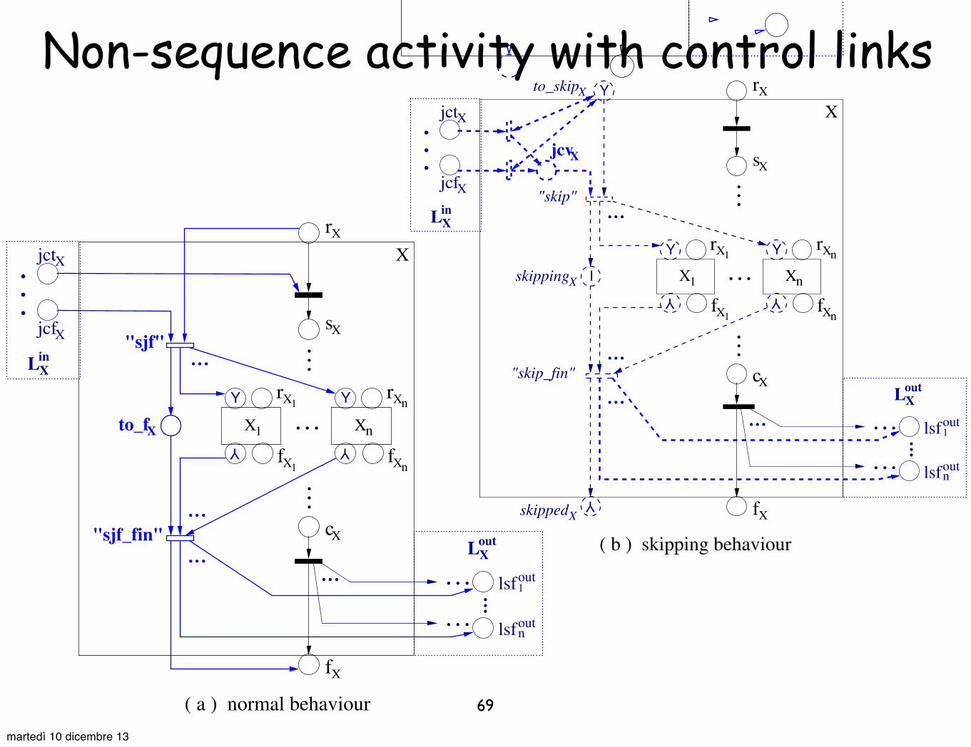
Non-sequence activity with control links
69
The subnet enclosed in the box labeled Loutx specifies the mapping of outgoing links from activity X.
Once X is complete, it is ready to evaluate transition conditions, which determine the link status for eachof the outgoing links. Since transition condition expressions are part of the data perspective, they arenot explicitly specified in the mapping and their boolean evaluation is modelled non-deterministically.
The subnet enclosed in the box labeled Linx specifies the mapping of incoming links to activity X. A
join condition is defined as a boolean expression (e.g. !X (ls in1 ,...,ls in
m )) in the set of variables representingthe status of each of the incoming links. It is mapped to a boolean net (BNx), which takes the statusof all incoming links as input and produces an evaluation result as output to place jctx (“join conditiontrue”) or jcfx (“join condition false”). The definition of this boolean net is given in Sect. 4.2.
If the join condition evaluates to true, activity X can start as normal. Otherwise, a fault calledjoin failure occurs. A join failure can be handled in two di!erent ways, as determined by a so-calledsuppressJoinFailure attribute associated with X. If this attribute is set to yes, the join failure willbe suppressed, as modelled by transition “sjf” (“suppress join failure”). In this case, the activity willnot be performed and the status of all outgoing links will be set to false. This is known as dead pathelimination in the sense that suppressing a join failure has the e!ect of propagating the false link statustransitively along the paths formed by control links, until a join condition is reached that evaluates totrue. An activity for which a join failure is suppressed, will end up in the “finished” state (e.g. fx) as if itis completed as normal, and thus the processing of any following activity will not be a!ected. Otherwise,if suppressJoinFailure is set to no, a join failure needs to be thrown, which triggers a standard faulthandling procedure as described in Sect. 3.5.
The mapping of skipping a basic activity with control links is shown in Fig. 6. Such an activity X, ifasked to skip, cannot be skipped until the status of all incoming links has been determined. Place jcvxis used to collect either true or false token which represents the corresponding result of join conditionevaluation, as such result will not a!ect the skipping behaviour of X. In this way, we capture the controldependency between activity X and the source activity of each of the incoming links to X. As soon asactivity X is skipped, the status of each of the outgoing links from X will be set to false, which capturesthe dead path elimination as a result of skipping the activity.
jcfX
jctX
jcvX
. . . .. .
X
Xin
X
X
X
r
c
f
s
X
X
.
L
.
.
LXout"skip"
Y
Y
.
..
. . .
. . .
out1
noutlsf
lsf
skipped
X
X
to_skip
Fig. 6. Mapping of skipping a basic activity with control links.
. ..
. . .
Xto_f
.
..
.
..
. . .. . .
Xr
Xn
Xn
jcfX
jctX
XLin
.
.
.
.... . .
. . .
LXout
out1
noutlsf
lsf
X
Xs
Xc
Xf
X1
X1
X1
f
rY
Y
Xn
r
f
Y
Y
. . .
"sjf_fin"
"sjf"...
.
..
Xc
Xr
. ..X1 Xn
Xn
Xn
jcfX
jctX
XLin
.
.
.
.... . .
. . .
LXout
out1
noutlsf
lsf
Xs
X
Xf
Y
Y
X1
X1
r
f
r
fI
. . .
Y Y
Y Y
"skip_fin"
"skip"
to_skipX
skippedX
skipping
. . .. . .
. . .
Xjcv
X
( a ) normal behaviour ( b ) skipping behaviour
Fig. 7. A non-sequence structured activity with control links.
8
martedì 10 dicembre 13

The previous example
70
which, together with the associated notions of join condition and transition condition, support thedefinition of precedence, synchronization and conditional dependencies on top of those captured by thestructured activity constructs. A control link between activities A and B indicates that B cannot startbefore A has either completed or has been “skipped”. Moreover, B can only be executed if its associatedjoin condition evaluates to true, otherwise B is skipped. This join condition is expressed in terms ofthe tokens carried by control links leading to B. These tokens may take either a positive (true) or anegative (false) value. An activity X propagates a token with a positive value along an outgoing link Lif and only if X was executed (as opposed to being skipped) and the transition condition associated toL evaluates to true. Transition conditions are boolean expressions over the process variables (just likethe conditions in a switch activity). The process by which positive and negative tokens are propagatedalong control links, causing activities to be executed or skipped, is called dead path elimination.
Control links may cross the boundaries of most structured activities. However, they must not createcyclic control dependencies and must not cross the boundary of a while activity or a serializable scope.4Prior to our work, the interaction between structured activities and control links was not fully under-stood, resulting in ambiguities and contradictions in the wording of the BPEL specification [5]. Followingour formalisation e!ort, some of these issues were reported and discussed in the BPEL standardisationcommittee, and changes to the specification’s wording have been proposed, albeit not yet adopted (seefootnote 3).
Also, whilst the control flow constructs of BPEL have been designed in a way to ensure that noBPEL process execution can deadlock5, some combinations of structured activities (in particular switchand pick) with control links can lead to situations where some activities are “unreachable”. Consider theBPEL process definition in Fig. 1 where both the XML code and a graphical representation are provided.During the execution of this process, either A1 or A2 will be skipped because these two activities areplaced in di!erent branches of a switch and in any execution of a switch only one branch is taken. Thus,one of the two control links x1 or x2 will carry a negative token. On the other hand, we assume thatthe join condition attached to activity A3 (denoted by keyword “AND”) evaluates to true if and only ifboth links x1 and x2 carry positive values. Hence, this join condition will always evaluate to false andactivity A3 is always skipped (i.e. it is unreachable).
<invoke name = "A3">
AND
A1 A2
x2
x1
A3
SW
FL
c1 c2
Flow
Switch
Control Link
Legend:
Basic Activity
<process name="unreachableTask"
<flow name="FL" suppressJoinFailure="yes"><links> <link name="x1"/> <link name="x2"/></links><switch name="SW"> <case> <invoke name="A1"> <sources> </invoke> </case> <otherwise> <invoke name="A2"> <sources> </invoke> </otherwise></switch>
<targets> <joinCondition>
</joinCondition> <target linkName="x1"/> <target linkName="x2"/> </targets></invoke> </flow>
</process>
<source linkName="x1"/> </sources>
</sources>
targetNamespace="http://samples.otn.com" suppressJoinFailure="yes" xmlns:tns="http://samples.otn.com" xmlns:services="http://services.otn.com" xmlns="http://schemas.xmlsoap.org/ws/2003/03/business!process/">
bpws:getLinkStatus(‘x1’) and bpws:getLinkStatus(‘x2’)
<source linkName="x2"/>
Fig. 1. Example of a BPEL process with an unreachable activity.
4 Serializable scopes are not covered in this paper since they are not a control-flow construct and thus falloutside the scope of this work. Instead, serializable scopes are fundamentally related to data manipulation.
5 Although it has not been formally proved that BPEL processes are deadlock-free, to the best of our knowledgeno example of a deadlocking BPEL process has been put forward. Also, Kiepuszewski et al. [14] provesthat synchronizing workflows (a subset of BPEL processes made up of elementary actions, control links,and restricted forms of join conditions) are non-deadlocking. Note that here we refer to “individual BPELprocesses” as opposed to “sets of communicating BPEL processes” which are outside the scope of our work.
3
We now extend the mapping of control links for structured activities. This is shown in Fig. 7 whichincludes mappings for both (a) normal behaviour and (b) skipping behaviour of a non-sequence activity.For the mapping of suppressing a join failure in Fig. 7(a), place to fx is added to capture an intermediatestate when activity X waits for all its sub-activities X1 to Xn to be skipped, before it is finished (fx).For both mappings in Fig. 7(a) and (b), the dead path elimination is captured upon the completion ofsuppressing the join failure (transition “sjffin”) or skipping all sub-activities of X (transition “skipfin”).The mapping for a sequence activity can be extended in a similar way, as shown in Fig. 8. Note thatthere is an exclusive choice between the normal behaviour (Fig. 7 (a) and Fig. 8 (a)) and the skippingbehaviour (Fig. 7 (b) and Fig. 8 (b)), because the environment puts a token in either place rx or to skipx.
Xn
Xn
. . .
to_fX
Xf
Xn
Xn
. . .
...
rX
skippedX
jctX
jcfX
XLin
...
XLin
jctX
jcfX
.
.
.
.... . .
. . .
LXout
out1
noutlsf
lsf .... . .
. . .
LXout
out1
noutlsf
lsf......
to_skipX
skippingX
X1
X2
XnXn
X2
X1
( a ) normal behaviour ( b ) skipping behaviour
X
r
f
c"sjf_fin"
X2
2
r
Xf
rX
X
X1
X1
s
r
f
X
"sjf"
X
r
f
c
X2
2
r
Xf
X
X1
X1
s
r
f
X
Y
...
Xf
Y
Y
I
Y
Y
Y
Y
Y
.
.
.
"skip"Y
Y
Y
Y
Y
Y
...
jcv
"skip_fin"
X
Fig. 8. A sequence activity with control links.
As an example, Figure 9 depicts the mapping of the BPEL process shown in Figure 1.
"c1"
FL
rFL
cFL
fFL
cSW
fSW
rSW
sSW
Y Y
Y Y"~c1 c2"v
tc
tc
"tt"
"ff"
"tf"
"ft"
r
s
A3
c
f
c
s
r
f f
c
A2
s
A2r
jct
jcflsf
lstlsf
lst
A1
A1 A2
A2A1
A1 A2
A3
A3
A3
A3
A1x2
x1
x2
x2
x1
A3
A3
x1
s
Fig. 9. Mapping of the BPEL process shown in Figure 1.
9
martedì 10 dicembre 13

Scope
71
Remind that a scope has a primary activity, and optionally:a set of fault handlers,
a set of event handlers, andone compensation handler.
To deal with them, four “flags” are attached to a scope:to_continue (no exception, execution is in progress)to_stop (an error occurred, activities need to stop)snapshot (successfully completed, uncompensated)
no_snapshot (no compensation needed)
In the following, we just sketch the handling of faults
martedì 10 dicembre 13

Scope
72
3.3 Scopes
A scope is a special type of structured activity defined for event and exception handling. It has aprimary (i.e. main) activity, and can provide event handlers (Sect. 3.4), fault handlers (Sect. 3.5) anda compensation handler (Sect. 3.6). Like other structured activities, scopes can be nested to arbitrarydepth, and the whole process is implicitly regarded as the top level scope.
To facilitate the mapping of exception handling, we define four flags for a scope. These are: to continue,indicating the execution of the scope is in progress and no exception has occurred; to stop, signaling anerror has occurred and all active activities nested in the scope need to stop; snapshot, capturing the scopesnapshot defined in [5] which refers to the preserved state of a successfully completed uncompensatedscope; and no snapshot, indicating the absence of a scope snapshot.
Fig. 10 depicts the basic mapping for a scope (Q) in which the mapping of any event or exceptionhandler associated with the scope is not included. Assume that no exception occurs. Scope Q remains inthe status of to continue during its normal performance (i.e. the execution of Q’s main activity A). Uponthe completion of activity A, a snapshot is preserved for scope Q. Next, consider the case of skippingscope Q (see Fig. 10(a)) or the case of suppressing a join failure for Q (see Fig. 10(b)). Once activity Ahas been skipped (upon the occurrence of transition “skip fin” or “sjf fin”), the status indicating theabsence of a scope snapshot for Q (place no snapshotQ) will be recorded. Finally, faults may occur duringthe normal performance of scope Q, causing the status of Q to change from to continue to to stop. Thiswill be described further in Sect. 3.5.
( b ) suppressing join failure
to_stopX
to_continueQC
snapshotQ
:)
Qno_snapshotskippedQ
Qskipping
to_skipQ
Q
A
A
A
Qr
s
r
f
YQ
Q
Q
c
f
Y !
Y
I
Y
"skip_fin"
"skip"
( a ) skipping behaviour
Qr
Qs
Qc
snapshotQ
:)
Qno_snapshot ! Qf
jctQ
jcfQ
QinL
to_fQ
LXout
.... . .
. . .
out1
noutlsf
lsf
Qto_stopX
to_continueQC
Ar
A
Af
.
.
.
"sjf"
"sjf_fin"
Y
Y
Q
. ..
. . .
Q
Fig. 10. A scope with its main activity.
3.4 Event Handlers
A scope can provide event handlers that are responsible for handling normal events (i.e. message or alarmevents) that occur concurrently while the scope is running. A message event handler can be triggeredmultiple times if the expected message event occurs multiple times, and an alarm event handler, exceptfor a repeatEvery alarm, can be invoked at most once (upon timeout). The repeatEvery alarm eventoccurs repeatedly upon each timeout when the scope is active, and the corresponding event handler canbe invoked multiple times as long as the alarm event occurs.
We discuss a couple of decisions made for the mapping of event handlers. Firstly, since no controllinks are allowed to cross the boundary of event handlers, each event handler can be viewed as anindependent unit of activities within a scope. Secondly, the occurrence of an event is either triggered bythe system (for an alarm event) or by the environment (for a message event), and the event handler isinvoked only if the expected event occurs. So it is not necessary to distinguish between the mappingsof the di!erent types of event handlers.
Fig. 11 depicts the mapping of a scope (Q) with an event handler (EH). The four flags associatedwith the scope are omitted. The subnet enclosed in the box labeled EH specifies the mapping of eventhandler EH. As soon as scope Q starts, it is ready to invoke EH. Meanwhile, event enormal is enabledand may occur upon an environment or a system trigger. When enormal occurs, an instance of EH iscreated, in which activity HE (“handling event”) is executed. EH remains active as long as Q is active.Finally, event enormal becomes disabled once the normal process of Q (i.e. Q’s main activity A) is finished.
10
3.3 Scopes
A scope is a special type of structured activity defined for event and exception handling. It has aprimary (i.e. main) activity, and can provide event handlers (Sect. 3.4), fault handlers (Sect. 3.5) anda compensation handler (Sect. 3.6). Like other structured activities, scopes can be nested to arbitrarydepth, and the whole process is implicitly regarded as the top level scope.
To facilitate the mapping of exception handling, we define four flags for a scope. These are: to continue,indicating the execution of the scope is in progress and no exception has occurred; to stop, signaling anerror has occurred and all active activities nested in the scope need to stop; snapshot, capturing the scopesnapshot defined in [5] which refers to the preserved state of a successfully completed uncompensatedscope; and no snapshot, indicating the absence of a scope snapshot.
Fig. 10 depicts the basic mapping for a scope (Q) in which the mapping of any event or exceptionhandler associated with the scope is not included. Assume that no exception occurs. Scope Q remains inthe status of to continue during its normal performance (i.e. the execution of Q’s main activity A). Uponthe completion of activity A, a snapshot is preserved for scope Q. Next, consider the case of skippingscope Q (see Fig. 10(a)) or the case of suppressing a join failure for Q (see Fig. 10(b)). Once activity Ahas been skipped (upon the occurrence of transition “skip fin” or “sjf fin”), the status indicating theabsence of a scope snapshot for Q (place no snapshotQ) will be recorded. Finally, faults may occur duringthe normal performance of scope Q, causing the status of Q to change from to continue to to stop. Thiswill be described further in Sect. 3.5.
( b ) suppressing join failure
to_stopX
to_continueQC
snapshotQ
:)
Qno_snapshotskippedQ
Qskipping
to_skipQ
Q
A
A
A
Qr
s
r
f
YQ
Q
Q
c
f
Y !
Y
IY
"skip_fin"
"skip"
( a ) skipping behaviour
Qr
Qs
Qc
snapshotQ
:)
Qno_snapshot ! Qf
jctQ
jcfQ
QinL
to_fQ
LXout
.... . .
. . .
out1
noutlsf
lsf
Qto_stopX
to_continueQC
Ar
A
Af
.
.
.
"sjf"
"sjf_fin"
Y
Y
Q
. ..
. . .
Q
Fig. 10. A scope with its main activity.
3.4 Event Handlers
A scope can provide event handlers that are responsible for handling normal events (i.e. message or alarmevents) that occur concurrently while the scope is running. A message event handler can be triggeredmultiple times if the expected message event occurs multiple times, and an alarm event handler, exceptfor a repeatEvery alarm, can be invoked at most once (upon timeout). The repeatEvery alarm eventoccurs repeatedly upon each timeout when the scope is active, and the corresponding event handler canbe invoked multiple times as long as the alarm event occurs.
We discuss a couple of decisions made for the mapping of event handlers. Firstly, since no controllinks are allowed to cross the boundary of event handlers, each event handler can be viewed as anindependent unit of activities within a scope. Secondly, the occurrence of an event is either triggered bythe system (for an alarm event) or by the environment (for a message event), and the event handler isinvoked only if the expected event occurs. So it is not necessary to distinguish between the mappingsof the di!erent types of event handlers.
Fig. 11 depicts the mapping of a scope (Q) with an event handler (EH). The four flags associatedwith the scope are omitted. The subnet enclosed in the box labeled EH specifies the mapping of eventhandler EH. As soon as scope Q starts, it is ready to invoke EH. Meanwhile, event enormal is enabledand may occur upon an environment or a system trigger. When enormal occurs, an instance of EH iscreated, in which activity HE (“handling event”) is executed. EH remains active as long as Q is active.Finally, event enormal becomes disabled once the normal process of Q (i.e. Q’s main activity A) is finished.
10
martedì 10 dicembre 13

Faults
73
BPEL defines three kinds of faults:
application faults (also service faults)generated by invoked services
process-defined faultsgenerated by a <throw> activity
system faultsgenerated by the process engine, such as join failures
“it is never possible to run more than one fault handler for the same scope, under any circumstances”
martedì 10 dicembre 13

Some assumptions
74
It is not shown entirely here, but the scope is encoded in such a way that when the token is in to_stop
(instead of to_continue)all active activities in the scope are by-passed:
they will be terminated reaching their “finished” state
We do not show the case of a fault occurred during the faulty mode of a scope (it is handled by the parent scope)
Control links are only allowed to leave the boundary of a fault handler: we do not show dead-path elimination for them
martedì 10 dicembre 13

By-pass a basic activity
75
. . .
1<scope name=" ">Q1<scope name=" ">
...
...
...
...
</activity >Ai
...Q1<compensate scope=" ">
...
FHi(of )
<activity >Ai
Q CHi<scope name=" ">
...
Q1(of )
...
<activityA>
<compensationHandler>
<throw faultname="fault">
<activity
</activity</compensationHandler>
</compensationHandler>
</scope>
<faultHandlers><catch faultName="fault">
activity</catch>
</faultHandlers>
<compensationHandler><scope name="Q">
activity</scope>
</activity></scope>
HC >1
HC >1
sthrow
cthrow
fthrow
rthrow
HC1r
to_invokeCH1
HC1f
!
:)
CH1
Q1
f
c
compensates
compensater
compensate
compensate
compensate
Q iCH
A i
...
...
throw
X
C iFH. . .
. . .
. .
.
. . .
. . .
A
CH
Q
. . .
Q
Fig. 20. Handling faults thrown from within a compensate handler.
Termination of a scope due to a fault The main activity of a scope needs to terminate when thescope is faulty. If the fault has been handled successfully, the scope will end as if it is completed normallyand thus the processing of its parent scope will not be a!ected. Also, the control dependencies shouldbe preserved during activity termination. Hence, for the mapping of activity termination, we adopt anapproach of conducting a dry run of the activity without performing its concrete actions (i.e. the coreaction of each basic activity) nor allowing it to process any normal events (i.e. message or alarm events).
Fig. 21 depicts the mapping for the termination of a basic activity with suppressJoinFailureattribute set to (a) yes or (b) no. We assume that activity X is directly enclosed in scope Q and hasincoming and outgoing links. As shown in both mappings, the core action of X (transition X) can beperformed only if Q is allowed to continue its normal process. Otherwise, if Q is asked to stop, the coreaction of X will be bypassed, as captured by the !-transition “bypass”. The dead path elimination isrealised by imposing an additional condition to link status evaluation of each outgoing link from X, suchthat a true status may be obtained only if Q is in the normal processing mode.
Suppose that a join failure occurs at activity X when X is required to terminate. A dry run ofsuppressing join failure is performed by transition “sjf” shown in Fig. 21 (a). However, it is not possibleto conduct a dry run of throwing join failure to scope Q when Q needs to stop. Recall the mapping ofhandling a join failure fault in Fig. 15, where ejoinf may be triggered only within the normal process of Q.In order to continue the dry run of activity X which attempts to throw a join failure during terminationof scope Q, we add transition “ignore” to the mapping in Fig. 21 (b). This transition will fire if a joinfailure occurs at X and X needs to terminate. As a result, the join failure is ignored and the dry run ofX is continued.
out
inX
jctX
jcfX
Qto_stop
XLout
lstouttcout
( a ) suppressJoinFailure = yes
X
X
CX
rX
X
X
X
s
c
f
"bypass"Qto_continue
"sjf"
lsfout
LinX
jctX
jcfX
XLout
tcout
X
X
X C
( b ) suppressJoinFailure = no
X
X
X
Xr
s
c
f
to_stopQ
to_continueQ"bypass"
"ignore"
lsfout
lst
L
Fig. 21. Termination of a basic activity.
17
. . .
1<scope name=" ">Q1<scope name=" ">
...
...
...
...
</activity >Ai
...Q1<compensate scope=" ">
...
FHi(of )
<activity >Ai
Q CHi<scope name=" ">
...
Q1(of )
...
<activityA>
<compensationHandler>
<throw faultname="fault">
<activity
</activity</compensationHandler>
</compensationHandler>
</scope>
<faultHandlers><catch faultName="fault">
activity</catch>
</faultHandlers>
<compensationHandler><scope name="Q">
activity</scope>
</activity></scope>
HC >1
HC >1
sthrow
cthrow
fthrow
rthrow
HC1r
to_invokeCH1
HC1f
!
:)
CH1
Q1
f
c
compensates
compensater
compensate
compensate
compensate
Q iCH
A i
...
...
throw
X
C iFH. . .
. . .
. .
.
. . .
. . .
A
CH
Q
. . .
Q
Fig. 20. Handling faults thrown from within a compensate handler.
Termination of a scope due to a fault The main activity of a scope needs to terminate when thescope is faulty. If the fault has been handled successfully, the scope will end as if it is completed normallyand thus the processing of its parent scope will not be a!ected. Also, the control dependencies shouldbe preserved during activity termination. Hence, for the mapping of activity termination, we adopt anapproach of conducting a dry run of the activity without performing its concrete actions (i.e. the coreaction of each basic activity) nor allowing it to process any normal events (i.e. message or alarm events).
Fig. 21 depicts the mapping for the termination of a basic activity with suppressJoinFailureattribute set to (a) yes or (b) no. We assume that activity X is directly enclosed in scope Q and hasincoming and outgoing links. As shown in both mappings, the core action of X (transition X) can beperformed only if Q is allowed to continue its normal process. Otherwise, if Q is asked to stop, the coreaction of X will be bypassed, as captured by the !-transition “bypass”. The dead path elimination isrealised by imposing an additional condition to link status evaluation of each outgoing link from X, suchthat a true status may be obtained only if Q is in the normal processing mode.
Suppose that a join failure occurs at activity X when X is required to terminate. A dry run ofsuppressing join failure is performed by transition “sjf” shown in Fig. 21 (a). However, it is not possibleto conduct a dry run of throwing join failure to scope Q when Q needs to stop. Recall the mapping ofhandling a join failure fault in Fig. 15, where ejoinf may be triggered only within the normal process of Q.In order to continue the dry run of activity X which attempts to throw a join failure during terminationof scope Q, we add transition “ignore” to the mapping in Fig. 21 (b). This transition will fire if a joinfailure occurs at X and X needs to terminate. As a result, the join failure is ignored and the dry run ofX is continued.
out
inX
jctX
jcfX
Qto_stop
XLout
lstouttcout
( a ) suppressJoinFailure = yes
X
X
CX
rX
X
X
X
s
c
f
"bypass"Qto_continue
"sjf"
lsfout
LinX
jctX
jcfX
XLout
tcout
X
X
X C
( b ) suppressJoinFailure = no
X
X
X
Xr
s
c
f
to_stopQ
to_continueQ"bypass"
"ignore"
lsfout
lst
L
Fig. 21. Termination of a basic activity.
17
ignore join-failurewhen to_stop
martedì 10 dicembre 13

A fault handler (general case)
76
Q
<faultHandlers><catch faultName="fault">
activityHF
<scope name="Q">
</scope>
</catch>
activityA
!
X
C
FHinvoked
FHto_invoke
"efault"
Qto_stop
Qto_continue
Q
Q
no_snapshotQ
FH
HF
A
A
A
Q
r
s
r
c
fQ
fHF
HF
r
f
Q
:) snapshot
</faultHandlers>
Fig. 13. A fault handler (general mapping).
The above throw activity in A
X
C
.. .
Af
Qc
rthrow
sthrow
cthrow
fthrow
.. .Q
Q
A
r
s
r
snapshotQ
:)no_snapshotQ! Qf
HFt
throw
A
Q
HF
HF
FHt
r
f
t
t
tto_invokeFH
FHinvoked t
.
..
.
..
</scope>
</faultHandlers></catch>
<activityA>
</activityA>
<throw faultName="fault"/>
<faultHandlers><catch faultName="fault">
<scope name="Q">
activityHFt
[note]is directly enclosed in scope Q.
Fig. 14. Handling a process-defined fault generated by the throw activity.
Handling a join failure fault. We instantiate the general mapping of a fault handler for a join failurefault, as shown in Fig. 15. Assume that activity X, which is part of the normal process of scope Q andis directly enclosed Q, has the suppressJoinFailure attribute set to no. The occurrence of fault eventejoinf will be triggered if a join failure occurs (place jcfX being marked) at activity X and X is ready tostart (place rX being marked). The arc from transition “ejoinf” to place sX allows the continuation of theflow in the normal process of scope Q. This is necessary in the mapping of activity termination (seeSection 3.7) which requires a dry run of the uncompleted activities in the scope.
Handling faults occurred within fault handlers. Any type of activity (e.g. a scope) can be usedfor fault handling, and thus the main activity carried out by a fault handler may contain scope activitiesthat are nested to arbitrary depth. If a fault occurred within a fault handler can be solved inside thefault handler, the mapping of fault handling shown in Fig. 13 can be used. Otherwise, if the fault cannotbe solved locally, it needs to be thrown to outside of the fault handler. Fig. 16 depicts the mappingof throwing a fault from within a fault handler (FH1) of the current scope (Q1), which invokes thefault handler (FH) for the parent scope (Q) of Q1. Note that the BPEL specification [5] also defines arethrow activity, which in essence “can be considered a macro for a <throw> (i.e. throw activity) thatthrows the fault caught by the corresponding fault handler” but cannot be solved by that fault handler(Section 13.4 of [5]).
13
efault is only enabledwhile A is running
martedì 10 dicembre 13

Example: process-defined fault
77
Q
<faultHandlers><catch faultName="fault">
activityHF
<scope name="Q">
</scope>
</catch>
activityA
!
X
C
FHinvoked
FHto_invoke
"efault"
Qto_stop
Qto_continue
Q
Q
no_snapshotQ
FH
HF
A
A
A
Q
r
s
r
c
fQ
fHF
HF
r
f
Q
:) snapshot
</faultHandlers>
Fig. 13. A fault handler (general mapping).
The above throw activity in A
X
C
.. .
Af
Qc
rthrow
sthrow
cthrow
fthrow
.. .
Q
Q
A
r
s
r
snapshotQ
:)no_snapshotQ! Qf
HFt
throw
A
Q
HF
HF
FHt
r
f
t
t
tto_invokeFH
FHinvoked t
.
..
.
..
</scope>
</faultHandlers></catch>
<activityA>
</activityA>
<throw faultName="fault"/>
<faultHandlers><catch faultName="fault">
<scope name="Q">
activityHFt
[note]is directly enclosed in scope Q.
Fig. 14. Handling a process-defined fault generated by the throw activity.
Handling a join failure fault. We instantiate the general mapping of a fault handler for a join failurefault, as shown in Fig. 15. Assume that activity X, which is part of the normal process of scope Q andis directly enclosed Q, has the suppressJoinFailure attribute set to no. The occurrence of fault eventejoinf will be triggered if a join failure occurs (place jcfX being marked) at activity X and X is ready tostart (place rX being marked). The arc from transition “ejoinf” to place sX allows the continuation of theflow in the normal process of scope Q. This is necessary in the mapping of activity termination (seeSection 3.7) which requires a dry run of the uncompleted activities in the scope.
Handling faults occurred within fault handlers. Any type of activity (e.g. a scope) can be usedfor fault handling, and thus the main activity carried out by a fault handler may contain scope activitiesthat are nested to arbitrary depth. If a fault occurred within a fault handler can be solved inside thefault handler, the mapping of fault handling shown in Fig. 13 can be used. Otherwise, if the fault cannotbe solved locally, it needs to be thrown to outside of the fault handler. Fig. 16 depicts the mappingof throwing a fault from within a fault handler (FH1) of the current scope (Q1), which invokes thefault handler (FH) for the parent scope (Q) of Q1. Note that the BPEL specification [5] also defines arethrow activity, which in essence “can be considered a macro for a <throw> (i.e. throw activity) thatthrows the fault caught by the corresponding fault handler” but cannot be solved by that fault handler(Section 13.4 of [5]).
13
fault due to throw activity
martedì 10 dicembre 13

Example: system fault
78
fault due to join-failure
FH
X is directly enclosed in scope Q.
...
. . .
. . .<target linkname= >
...
<activityA>
<scope name="Q">
</faultHandlers>
<faultHandlers><catch faultname="bpws: joinFailure">
</catch>
<activityX suppressJoinFailure="no">
</activityA></scope>
<targets><joinCondition>
</joinCondition>
</targets></activityX>
activity HFjf
:)
C
X
!
.. ... .
"ejoinf "
jctX
jcfX
Q
rQ
sQ
rA
fA
c
fQ
Q
rHF
fHF
HF
FH
r
s
c
f
X
X
AX
X
X
X
jf
jf
jf
jf
to_invokeFHjf
jfinvoked
[note]
Fig. 15. Handling a join failure as an example of a system fault.
f
1[note]
.
..Q1<scope name=" ">
.
..
.
..
.
..
</catch></faultHandlers><activityA>
<faultHandlers><catch faultName="fault">
<scope name="Q"><faultHandlers>
<catch faultname="fault">
</catch></faultHandlers>
</scope>
</activityA> </scope>
activity (of FH )t
activity (of Q )1
<rethrow/>
X
C to_continue Q
to_stopQ
.
.
.
FHinvoked t
FHt
tto_invokeFH
rthrow
sthrow
cthrow
fthrow
..
.
..
. FH1
rFH1
fFH1
.
.
.
Q1
.. .
Af
Ar
Q
Q
r
s
.. .
...
throw
A
Q
Q
Q is directly enclosed in scope Q.
Fig. 16. Handling a fault thrown from within a fault handler.
Handling faults occurred in a scope with event handlers. Since event handlers are considered aspart of the normal process of a scope, faults occurred within a scope include those occurred within theevent handlers attached to the scope. Fig. 17 depicts the mapping of handling a fault occurred withina scope that has event handlers attached to it. This mapping is mainly obtained by combining themappings of event handling (Fig. 11) and fault handling (Fig. 13) for the scope. Based on this, we addthe following two arcs, both drawn in thick dashed lines. The arc from place to invokeEH to the inputtransition of place rHF, is added to ensure that any active instance of event handler (EH) will terminatebefore the fault handling (activity HF) starts. The bidirectional arc connecting place to continueQ andtransition “enormal”, is added to disable event enormal once a fault occurs within scope Q.
14
martedì 10 dicembre 13

Expressiveness...not in the formal sense
(w.r.t. WF patterns)
79
martedì 10 dicembre 13

80
Basic Control Flow Patterns
• Pattern 1 (Sequence)
• Pattern 2 (Parallel Split)
• Pattern 3 (Synchronization)
• Pattern 4 (Exclusive Choice)
• Pattern 5 (Simple Merge)
Advanced Branching and
Synchronization Patterns
• Pattern 6 (Multi - choice)
• Pattern 7 (Synchronizing Merge)
• Pattern 8 (Multi - merge)
• Pattern 9 (Discriminator)
Structural Patterns
• Pattern 10 (Arbitrary Cycles)
• Pattern 11 (Implicit Termination)
State-based Patterns
• Pattern 16 (DeferredChoice)
• Pattern 17 (InterleavedParallel Routing)
• Pattern 18 (Milestone)
Patterns involving Multiple Instances
• Pattern 12 (Multiple Instances WithoutSynchronization)
• Pattern 13 (Multiple Instances With a PrioriDesign Time Knowledge)
• Pattern 14 (Multiple Instances With a PrioriRuntime Knowledge)
• Pattern 15 (Multiple Instances Without a PrioriRuntime Knowledge)
Cancellation Patterns
• Pattern 19 (Cancel Activity)
• Pattern 20 (Cancel Case)
Fig. 1. Overview of the 20 most relevant patterns.
WWW site” [48]. The patterns range from very simple patterns such as sequential rout-
ing (Pattern 1) to complex patterns involving complex synchronizations such as the
discriminator pattern (Pattern 9). In this paper, we restrict ourselves to the 20 most
relevant patterns. These patterns can be classified into six categories:
1. Basic control flow patterns. These are the basic constructs present in most workflow
languages to model sequential, parallel and conditional routing.
2. Advanced branching and synchronization patterns. These patterns transcend the
basic patterns to allow for more advanced types of splitting and joining behavior.
An example is the Synchronizing merge (Pattern 7) which behaves like an AND-
join or XOR-join depending on the context.
3. Structural patterns. In programming languages a block structure which clearly
identifies entry and exit points is quite natural. In graphical languages allowing for
parallelism such a requirement is often considered to be too restrictive. Therefore,
we have identified patterns that allow for a less rigid structure.
4. Patterns involvingmultiple instances.Within the context of a single case (i.e., work-
flow instance) sometimes parts of the process need to be instantiated multiple times,
e.g., within the context of an insurance claim, multiple witness statements need to
be processed.
5. State-based patterns. Typical workflow systems focus only on activities and events
and not on states. This limits the expressiveness of the workflow language because
it is not possible to have state dependent patterns such as the Milestone pattern
(Pattern 18).
martedì 10 dicembre 13
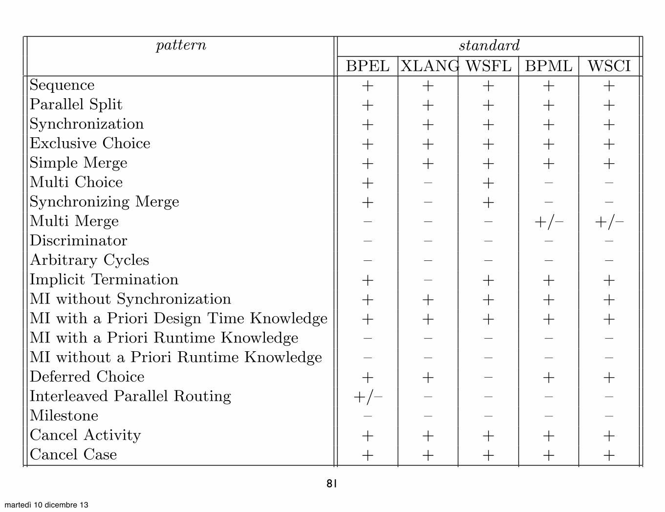
81
Pattern-Based Analysis of BPML (and WSCI) 24
pattern standardBPEL XLANG WSFL BPML WSCI
Sequence + + + + +Parallel Split + + + + +Synchronization + + + + +Exclusive Choice + + + + +Simple Merge + + + + +Multi Choice + – + – –Synchronizing Merge + – + – –Multi Merge – – – +/– +/–Discriminator – – – – –Arbitrary Cycles – – – – –Implicit Termination + – + + +MI without Synchronization + + + + +MI with a Priori Design Time Knowledge + + + + +MI with a Priori Runtime Knowledge – – – – –MI without a Priori Runtime Knowledge – – – – –Deferred Choice + + – + +Interleaved Parallel Routing +/– – – – –Milestone – – – – –Cancel Activity + + + + +Cancel Case + + + + +Request/Reply + + + + +One-Way + + + + +Synchronous Polling + + + + +Message Passing + + + + +Publish/Subscribe – – – – –Broadcast – – – – –
Table 1. Comparison of BPEL4WS, XLANG, WSFL, BPML and WSCI using bothworkflow and communication patterns.
– BPML does not o�er direct support for the Multi Choice and Synchro-nizing Merge while BPEL4WS does. This comes from the fact thatBPEL4WS borrows the concept of “dead-path elimination” charac-teristic of WSFL/IBM MQSeries.
– Each of the languages supports Multiple Instances without Synchro-nization, Multiple Instances with a Priori Design Time Knowledge,Cancel Activity, and Cancel Case.
– Most of the languages support the Implicit Termination and the De-ferred Choice.
– None of the compared languages support arbitrary cycles, althoughall of them directly support structured cycles.
When comparing BPEL4WS, XLANG, WSFL, BPML and WSCI tocontemporary workflow systems [3] on the basis of the patterns discussed
FIT Technical Report FIT-TR-2002-05
martedì 10 dicembre 13