Embed Size (px)
Citation preview
96 OPTICS LETTERS / Vol. 14, No. 1 / January 1, 1989
Method for propagation of total fields or beams through opticalwaveguides
Anurag Sharma and Swagata Banerjee
Department of Physics, Indian Institute of Technology Delhi, New Delhi 110016, India
Received November 9, 1987; accepted September 13, 1988
A new method for solving the scalar Helmholtz equation to obtain the propagation of total fields or beams throughgeneral optical waveguiding structures is presented. The method is based on converting the partial differentialequation into a matrix total differential equation using a collocation method and then solving the resulting equationthrough standard numerical methods. A comparison with the propagating-beam method shows that the presentmethod has better accuracy and is more efficient numerically.
The propagation characteristics of an optical wave-guide are usually described in terms of the waveguide'smodes, and the propagation of an incident fieldthrough the waveguide is studied by expanding theincident field in terms of various modes, which thenpropagate with definite propagation constants. Thisapproach, although well understood and easy to ma-nipulate, is applicable only to uniform waveguides.As such, alternative approaches to solve the scalar-wave equation directly and to study the propagation oftotal fields through waveguides have received in-creased attention.1-8 One such approach is the propa-gating-beam method1 -3 (PBM), which has been ap-plied to a variety of waveguide problems. 1-8 An ex-tensive discussion on this method and its applicabilityand limitations can be found in Refs. 5 and 6.
We have developed a new method for studying thepropagation of a field through a general waveguidingstructure. The method is applicable to all kinds ofprofiles as well as to waveguides that are nonuniformalong the direction of propagation. The method in-volves no inherent approximation and hence can bemade as accurate as desired. It is based on convertingthe scalar Helmholtz equation into a matrix equationusing the orthogonal collocation method9-"1 and solvingthe matrix equation numerically using any standardprocedure, such as the Runge-Kutta method. In thisLetter we describe the principle of our method and giveillustrative examples to show its accuracy and effective-ness. A comparison with PBM is also included, whichshows that our method is more accurate and more effi-cient numerically. Although the method is applicableto arbitrary waveguiding structures, for simplicity weconfine our discussion to planar guiding structures. Adiscussion on the applicability of our method to practi-cal guiding structures is also included.
The propagation characteristics of a planar mediumcharacterized by the index distribution n(x, z) is de-scribed by the scalar Helmholtz equation,
82 E + 2E k22(X,+-k 0 n2 (xz)E(x, z) = 0,OX2 OZ2 (1)
where E is a Cartesian component of the electric field
and ko = wic is the free-space wave number. The fieldis assumed to have a time dependence of exp(iwt). Tosolve Eq. (1) we expand E(x, z) in terms of a completeset of suitable functions ¢(x),
M
E(x, z) = E 40¢A),n=1
(2)
where Cn(z) are the expansion coefficients. For pla-nar guiding structures, kn(x) can be taken as the Her-mite-Gauss functions,12
On(X) = Hn-,(ax)exp(_%a2XI), (3)
where a is a constant that can be chosen arbitrarily.We make use of the principle of orthogonal colloca-tion10 to convert the partial differential equation inEq. (1) into a matrix total differential equation. Inthe orthogonal collocation method, the expansion co-efficients C,, are obtained by requiring that Eq. (1) issatisfied by expansion in Eq. (2) at M collocationpoints xm, m = 1, 2,. . ., M, where xm are given by
HM(axm) = 0. (4)The Hermite polynomial HM has M zeros, which arewell documented in the tables for the Hermite-Gaussintegration procedure.' 2' 13 Thus we get a set of Mtotal differential equations,
a 2E d2Em 22Xmd2E | + + k02o 2(Xm, z)Em(z) = 0,
ax2X=Xm dz2
m=1,2,...,M, (5)where Em(z) = E(x = xm, z). This set of equations canbe written as a matrix differential equation,
(d2/dz 2)E +D +R*E = 0; (6)
E = collEl, E2, E3,... ,EM
R = k02 diagln2 (x,), n2(x 2), n2 (x 3), .... , n2(XM)3,
D { =col X a'E a'a x2 x=x1 Ox2 X=X 2
0146-9592/89/010096-03$2.00/0 © 1989 Optical Society of America
I--- Ia'E � (7)ax2 x=xm
January 1, 1989 / Vol. 14, No. 1 / OPTICS LETTERS 97
are the matrices in Eq. (6). Equation (2) can be re-written in matrix form as
E = A * C, (8)
where
C = col{C1, C2, C3 , ... , CM),
A = 1Ai j1A jj = okj(xi), i, j E N, i, j < MI. (9)
Similarly, we can write D = B * C, where
B =B. IB aX2.
Using Eq. (8), we get D = B - A-' -E, and Eq. (6) thenbecomes
(d2/dz2)E + S * E(z) = 0, (11)
where
S = B * A-' + R. (12)
The field represented by vector E varies rapidly owingto a phase factor exp(-ikz), where k is a constant. Ingeneral, k could be taken as k0nci, where n~j is theindex of the cladding, which is known. Thus,
E(z) = X(z)exp(-ikz), (13)
where X(z) is a slowly varying function of z. Substitu-tion of E from Eq. (13) into Eq. (11) gives
d 2X dX-_ - 2ik - + (S - k2I)X(z) = 0, (14)
dz2 dz
where I is the unit matrix. Thus, we have a second-order matrix differential equation that can be solveddirectly using standard techniques such as the Runge-Kutta method or a predictor-corrector method. 12' 14
The solution E(z) represents the field at various collo-cation points in the transverse direction as a functionof the propagation distance z.
For a uniform waveguide, it is sufficient to considerthe parabolic equation3 that is obtained by neglectingthe second derivative of X:
(d/dz)X = (S - k2I)X(z)/(2ik). (15)
Even for a nonuniform waveguide, Eq. (15) is an excel-lent approximation and has been used in PBM.3-8
A few salient features of our method, particularly incomparison with the PBM, may be noted:
(1) In deriving the matrix equation [Eq. (14)], nophysical or mathematical approximation has beenmade. The only numerical approximation involved isthe finiteness of M. Obviously, one has to obtain anappropriate value of M by testing the convergencewith M for a desired accuracy. As M - -, Eq. (14) isexactly equivalent to the scalar-wave equation [Eq.(1)]. In PBM it is necessary to use the extendedFresnel approximation.2
(2) It is straightforward to obtain eigenvalues andeigenvectors in our method. For a mode, Eq. (11)reduces to a standard real matrix eigenvalue problemfor the propagation constant f,
S * E = 02E, (16)
which can easily be solved. On the other hand, toobtain eigenvalues and eigenvectors with PBM in-volves numerical propagation over exceedingly largedistances, and inaccuracies could be large where theamplitude of the field is small.3' 7
(3) In PBM, the transverse cross section is usedonly up to a finite extent, beyond which the fast-Fourier-transform procedure assumes that the guid-ing structure and field are periodic. Thus, one hasalways to assume the presence of a fictitious strong
) absorber in this latter region. There is no need forsuch an unrealistic assumption in our method.
To illustrate the accuracy and numerical efficiencyof our method, we consider the propagation of thefundamental mode in a uniform waveguide so that thechange in the propagating field distribution is a directmeasure of accuracy. We choose an index profile forwhich the field distribution as well as the propagationconstants are analytically known. Thus the numeri-cal calculations have been performed using the indexdistribution 1 5 :
n2 (x, z) = n22 + (n1
2 - n 22)sech 2 (x/a), (17)
with a = 3,um, nj = 1.45, and n2 = 1.4476. We assumethe free-space wavelength of the propagating wave tobe k, = 1.31 Am so that the V value [V = 2,-a(n, 2
-
n22 )1/ 2/XC] is 1.2. We consider the incidence of thefundamental mode of the straight waveguide at z = 0,i.e.,
E(x, z = 0) = cosh-W(x/a), (18)
where W-- a(j32 - 47r2n22/XC2)1/2 = '/2[(l + 4V2)1/2 - 1].As a measure of accuracy we have computed the corre-lation factor of the propagating field at z = 100 Amwith the fundamental mode. The absolute value ofthis factor should be unity. Thus, the error in thecorrelation factor, i.e., the difference of its absolute
0
.4ILL
0
4
0U
z
0
ML
2.0
w
I--
z0I.-4
1.0 EL0U
W
I.l
WM:
o10 30 50 70
NUMBER OF COLLOCATION POINTS
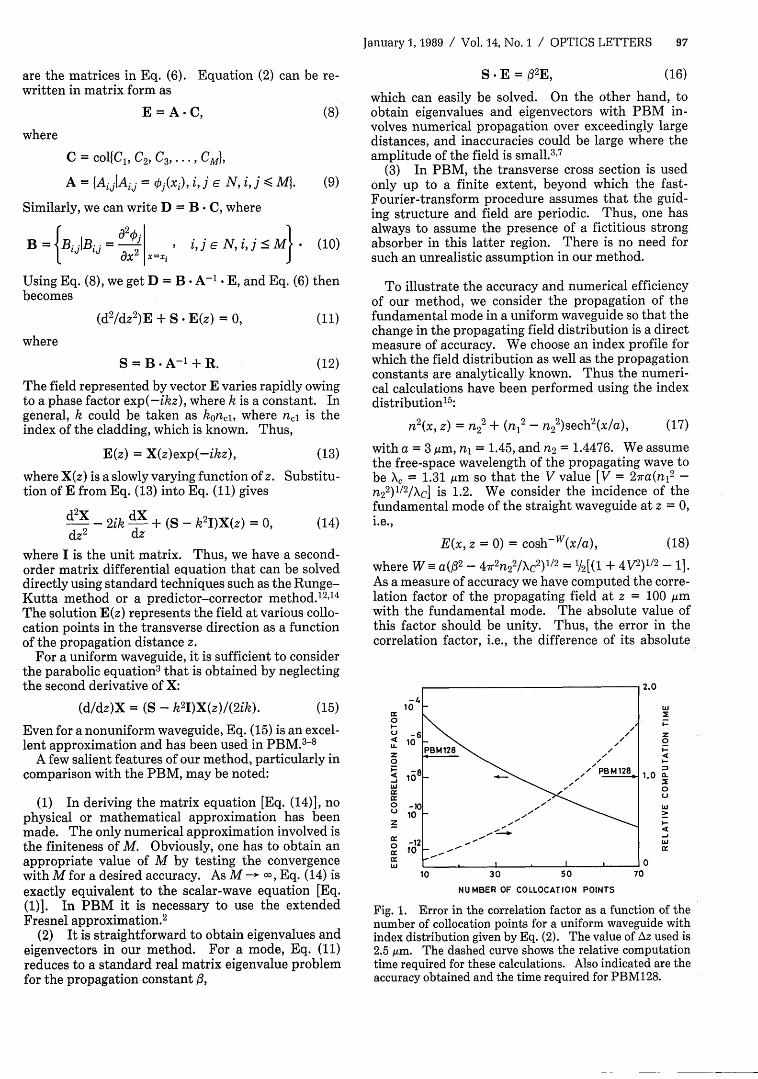
Fig. 1. Error in the correlation factor as a function of thenumber of collocation points for a uniform waveguide withindex distribution given by Eq. (2). The value of Az used is2.5 ,um. The dashed curve shows the relative computationtime required for these calculations. Also indicated are theaccuracy obtained and the time required for PBM128.
) ijFNi'j< - (10)

98 OPTICS LETTERS / Vol. 14, No. 1 / January 1, 1989
Table 1. Number of Multiplications in OnePropagation Stepa
OurPBMb Method
Two dimensional n(4 1og2 n + 1) 4M2
Three dimensional n2 (8 lg 2 n + 1) 4M2(2M + 1)Increment factor 2n 2M
(n, M >> 1)
a n, Number of sample points for fast-Fourier transform in PBM;M, number of collocation points in our method. For a desiredaccuracy, M << n (see Fig. 1).
b Ref. 5.
value from unity, is a direct measure of the accuracy ofthe method and is plotted as a function of M in Fig. 1.For comparison we have also included the results ob-tained using the PBM method with a grid of 128 points(PBM128) in the cross section between -50,4m and 50
ium. The value of Az is 2.5,um for all calculations. Toindicate the numerical efficiency of the method, wehave also plotted in Fig. 1 the computation time re-quired (relative to PBM128). The following observa-tions may be made from Fig. 1:
(1) The nonsaturating behavior of the curve forlarge values of M shows that the error can be reducedindefinitely by increasing M, as discussed above.
(2) The accuracy of -10-7 (which is obtained withPBM128) is obtained with 25 collocation points, andthe time required is less than one third of the timerequired by PBM.
(3) For collocation points, with M lying between25 and 54, our method gives better accuracy and re-quires shorter computation time in comparison withPBM128, hence our method is superior to PBM bothin accuracy and numerical efficiency.
Finally, we discuss the applicability of our methodto other guiding structures of practical importance.Our method can be extended easily to three-dimen-sional guiding structures. In this case, one has to use adouble linear expansion in terms of two sets of theHermite-Gauss functions along the x and y directions,and the field vector E then becomes a matrix specify-ing the field at a two-dimensional transverse grid ofcollocation points. The number of multiplications re-quired in the two-dimensional and three-dimensionalcases, which can be considered as a measure of com-plexity in the implementation of a numerical method,5are shown in Table 1. The increase in complexity inthree-dimensional cases over two-dimensional cases inour method is much smaller in comparison with PBMsince the number of collocation points required toachieve a desired accuracy is much smaller than thenumber of sample points needed in PBM. Further-more, if the three-dimensional guiding structure hascircular symmetry, as in the case of optical fibers (in-cluding tapers and expanders that retain the circularsymmetry), the Helmholtz equation reduces to a two-dimensional equation (for fields of one azimuthal sym-metry). In such cases, our method can be implement-ed as in the case of a two-dimensional guiding struc-ture using appropriate Laguerre-Gauss functions.
This could prove to be particularly useful for single-mode fibers and for devices based on them. There isno such possibility in PBM. The integrated-opticalcircuit elements, such as the branching elements,bends and corners, and crossing waveguides, can betreated with our method in the same way as withPBM, with advantages in computational effort similarto those discussed in this Letter, since in these casesthe only difference is that the refractive-index distri-bution is a more complex function of the position coor-dinates. This kind of situation is fully represented bythe Helmholtz equation and hence can evidently behandled by our method.
In conclusion, we have presented a new method tosolve the scalar Helmholtz equation numerically andto obtain the propagation of total fields through ageneral waveguide. The method yields better accura-cy and is more efficient numerically compared withPBM and has several advantages. The method, un-like PBM, needs no approximation and hence can beused for obtaining any desired accuracy.
Anurag Sharma is indebted to Sharad K. Gupta ofthe Chemical Engineering Department, Indian Insti-tute of Technology Delhi, for introducing him to thecollocation technique and for providing Ref. 10. Thisresearch was partially supported by a project spon-sored by the U.S. National Institute of Standards andTechnology and the Department of Science and Tech-nology, India.
References
1. J. A. Fleck, Jr., J. R. Morris, and M. D. Feit, Appl. Phys.10, 129 (1976).
2. M. D. Feit and J. A. Fleck, Jr., Appl. Opt. 17, 3990(1978).
3. M. D. Feit and J. A. Fleck, Jr., Appl. Opt. 18, 2843(1979).
4. D. Yevick and P. Danielson, J. Opt. Commun. 4, 94(1983).
5. J. Van Roey, J. van der Donk, and P. E. Lagasse, J. Opt.Soc. Am. 71, 803 (1981).
6. L. Thylen, Opt. Quantum Electron. 15, 433 (1983).7. D. Yevick and P. Danielson, Appl. Opt. 21, 2727 (1982).8. D. Yevick and B. Hermansson, Opt. Lett. 11, 103 (1986).9. L. A. Pipes and L. R. Harvill, Applied Mathematics for
Engineers and Physicists (McGraw-Hill, New York,1970), p. 583.
10. J. V. Villadsen and W. E. Stewart, Chem. Eng. Sci. 22,1483 (1967).
11. Collocation methods have been used extensively to solvepartial differential equations in chemical engineering(see, e.g., Ref. 10). The orthogonal collocation method,which was proposed in Ref. 10, has distinct advantagesover the general collocation method. The Hermite-Gauss functions in orthogonal collocation are used forthe first time, to our knowledge, in this Letter.
12. M. Abramowitz and I. A. Stegun, Handbook of Mathe-matical Functions (Dover, New York, 1970).
13. A. H. Stroud and D. Secrest, Gaussian Quadrature For-mulas (Prentice-Hall, Englewood Cliffs, N.J., 1966), p.217.
14. J. B. Scarborough, Numerical Mathematical Analysis(Oxford U. Press, London, 1966), p. 353.
15. M. J. Adams, An Introduction to Optical Waveguides(Wiley, New York, 1981), p. 132.


![Propagation of Bessel and Airy beams through atmospheric ... · modify the propagation of laser beams through atmosphere [1-7]. In weak atmospheric turbulence, the modifications can](https://img.pdfslide.us/doc/110x75/5f30f0d7fc73d56e2278b679/propagation-of-bessel-and-airy-beams-through-atmospheric-modify-the-propagation.jpg)