Embed Size (px)
Citation preview

(12) United States Patent Yeckley
US007392691B1
US 7,392,691 B1 Jul. 1, 2008
(10) Patent N0.: (45) Date of Patent:
(54)
(75)
(73)
(*)
(21)
(22)
(51)
(52) (58)
(56)
METHOD AND APPARATUS FOR 3,755,801 A * 8/1973 Milo ........................ .. 340/622
DETECTING THE LEVEL OFA LIQUID 4,949,069 A * 8/1990 Wilson .................. .. 340/450.1 6,431,750 B1 8/2002 Haberbusch et a1.
Inventor: algander J. Yeckley, Castalia, OH OTHER PUBLICATIONS
“Cryo-Tracker TM Level, Temperature, and Mass Gauging Fluid Sen Assignee: Sierra L0b0, Inc., Fremont, OH (US) SOTS”, Sierra Lobe, 111°» Aug 21, 2003, PP 1-9~*
* 't d b ' Notice: Subject to any disclaimer, the term of this C1 e y exammer
patent is extended or adjusted under 35 Primary ExamineriDaniel S. Larkin U.S.C. 154(b) by 130 days. (74) Attorney, Agent, or FirmiPearne & Gordon LLP
Appl. N0.: 11/255,416 (57) ABSTRACT
Filed; Oct_ 20, 2005 A system for determining the position of a gas/ liquid interface of a ?uid in a tank having a probe and a controller. The probe
Int. Cl. has silicon diodes arranged linearly on a substrate. The con G01F 23/22 (2006.01) troller applies poWer to each of the silicon diodes to make a US. Cl. ...................................... .. 73/64.55; 73/295 determination of Whether a ?uid in which the silicon diode is
Field of Classi?cation Search .............. .. 73/64.55, immersed is a liquid Or a gas based on a rate Oftransfer Ofheat 73/295 from the silicon diode to the ?uid. A method for determining
See application ?le for Complete Search history the phase of a ?uid in Which a sensor is immersed includes the steps of immersing the sensor in a ?uid and increasing poWer
References Clted applied to the sensor. The Value of a thermal transient of the
U S PATENT DOCUMENTS sensor is then measured and the phase of the ?uid is deter ' ' mined based on the measured Value of the thermal transient.
3,465,587 A * 9/1969 Pierce ....................... .. 73/295
3,734,123 A * 5/1973 Pomerantz ................ .. 137/392 24 Claims, 4 Drawing Sheets
1 6 14
26
1 8
1O 4/
NON VOLATILE ( ) MICROPROCESSOR ( } VOLATILE MEMORY MEMORY
22 1 2 24
US. Patent Jul. 1, 2008 Sheet 1 014 US 7,392,691 B1
18
10 4/
NON VOLATILE MICROPROCESSOR VOLATILE MEMORY MEMORY
22 12 24
FIG. 1

US. Patent Jul. 1, 2008 Sheet 2 of4 US 7,392,691 B1
310 S34
INITIALIZATION END LEARN MODE
S32 REPEAT LEARN MODE
s12 \UNTIL BOTH xa YCHANGE, AND STORE AS “LIQUID WARMING” & “LIQUID
START LEARN MODE COOLING” RESPECTIVELY
S30 S14 \ COMPUTE AVERAGE TIME
CONSTANT, Y, AND STORE AS “GAS COOLING
SWITCH ALL DIODES TO T TEMPERATURE MODE S28\
STORE tw ‘
S16
\ SWITCH ALL DIoDEs TO 0 LIQUID LEVEL MODE FOR <—- REDUCE tw BY 25/0
TIME tw
S24
TEMPER ATURE
S18 \ MEASURE TEMPERATURE
F DI DE 0 O S CHANGED?
S22
S20 \ COMPUTE AVERAGE TIME WAIT tc SECONDS &
CONSTANT, X, AND STORE ’ MEASURE TEMPERATURE AS “GAS WARMING” OF DIODES
FIG. 2

US. Patent Jul. 1, 2008 Sheet 3 of4 US 7,392,691 B1
S100
\ START PHASE STATE DETERMINATION
S102 Y / MEASURE TEMPERATURE
OF DIODE
I SWITCH DIODE TO LIQUID LEVEL MODE TO SELF HEAT FOR IWSECONDS
I MEASURE NEW
TEMPERATURE OF DIODE
I
S104
S106
S108 // CALCULATE TIME CONSTANT
S110
DIODE IS IN GAS
TIME CONSTANT > TIME
CONSTANT, X, IN LOOKUP TABLE?
YES
s114\ DIODE IS IN LIQUID —> WA” FOR D'ODE — TO COOL
\\S116 FIG. 3

US. Patent
S200
S202
S204
S206
S208
/ /
Jul. 1, 2008 Sheet 4 0f 4
DETERMINE THE PHASE STATE OF EACH ACTIVE
DIODE
STORE PHASE STATES IN VOLATILE MEMORY
DETERMINE LIQUID LEVEL BASED ON PHASE STATE
ACTIVATE DIODES ADJACENT TO LIQUID
LEVEL // DEACTIVATE UNNEEDED (NONADJACENT) DIODES
FIG. 4
US 7,392,691 B1

US 7,392,691 B1 1
METHOD AND APPARATUS FOR DETECTING THE LEVEL OF A LIQUID
This invention Was made With Government support under contract 13296-1 -02-C-0210 With the US . Air Force and fund ing provided by the Missile Defense Agency. The Govem ment has certain rights in the invention.
BACKGROUND OF THE INVENTION
The present invention relates to measuring the liquid level orposition of a gas/ liquid interface along the length of a probe and, in particular, to a probe for measuring the temperature and gas/ liquid interface position in a tank of cryogenic liquid.
In cryogenic liquid tanks (for example, propellant tanks for aerospace vehicles), it is important to knoW the temperature in various levels of the liquid and to knoW the level of the liquid Within the tank. As the density of the liquid varies With tem perature, this information is important to determine such values as the mass of the liquid in the tank.
Propellant tanks are usually more than 5 feet tall and typi cally in the range of 8 to 100 feet tall. One knoWn device for the measurement of the temperatures in these tanks includes temperature sensors mounted on a metallic rake-like structure consisting of vertical and horizontal beams With temperature sensors mounted at various locations on the rake. Typical temperature sensors include silicon diodes, thermocouples, thermopiles, thermistors, and RTDs.
Another type of probe used for taking measurements of cryogenic liquid in a tank is disclosed in US. Pat. No. 6,431, 750 to Haberbusch et al, Which is incorporated by reference herein. The probe disclosed therein is a lightweight elongate ?exible temperature probe including several temperature sen sors embedded inside multiple layers of a thin ?lm polyimide or polyester. In tWo of the layers, thin ?lm copper is etched to form conductors to the sensors. The conductors are in abut ting electrical contact With the sensors. Known temperature probes, such as those described above,
can be used to estimate the level of liquid the tank based on the temperatures sensed at various levels. HoWever, in a partially empty tank, the cryogenic liquid may evaporate to form a layer of cryogenic gas above the liquid. Therefore, it can be dif?cult to ascertain the precise level of the liquid, since the cryogenic gas may have a temperature very close to that of the liquid.
BRIEF SUMMARY OF THE INVENTION
According to one aspect, the present invention provides a system for determining the level of a liquid in a tank. The system comprises a probe comprising a plurality of silicon diodes arranged linearly on a substrate; and a controller for controlling poWer applied to each of the plurality of silicon diodes to make a determination of Whether a ?uid in Which the silicon diode is immersed is a liquid or a gas based on a rate of transfer of heat from the silicon diode to the ?uid.
According to a further aspect, the present invention pro vides a method for determining the phase of a ?uid in Which a sensor is immersed. The method comprises the steps of: immersing a sensor in a ?uid; increasing poWer applied to the sensor; measuring a value of a thermal transient of the sensor; and determining a phase of the ?uid based on the measured value of the thermal transient.
According to a further aspect, the present invention pro vides a method of determining a level of a liquid in a tank, the method comprises the steps of: installing a probe in the tank, the probe comprising a plurality of silicon diodes arranged
20
25
30
35
40
45
50
55
60
65
2 linearly on a substrate; immersing the probe in ?uid; increas ing poWer to at least tWo of the plurality of silicon diodes; measuring a value of a thermal transient of each of the silicon diodes; determining a phase of the ?uid at each of the at least tWo silicon diodes based on the measured value of the thermal transient; and determining a location of a gas/ liquid interface based on the phase determined for each of the at least tWo diodes.
BRIEF SUMMARY OF THE DRAWINGS
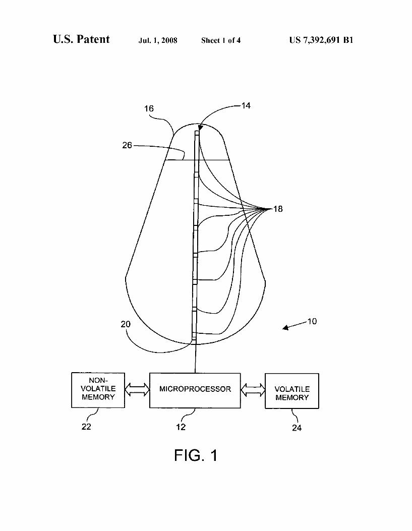
FIG. 1 is a schematic illustration of a liquid level and temperature sensing system installed on a cryogenic tank according to an example embodiment of the present inven tion;
FIG. 2 is a ?oW chart illustrating a learning process for the system of FIG. 1 according to an example embodiment of the present invention;
FIG. 3 is a ?oW chart illustrating a method of operating the system of FIG. 1 to determine the phase state of a ?uid in Which a silicon diode is immersed according to an example embodiment of the present invention; and
FIG. 4 is a ?oW chart illustrating a method of operating the system of FIG. 1 to determine the level of liquid in a tank according to an example embodiment of the present inven tion.
DETAILED DESCRIPTION OF THE INVENTION
According to the present invention, a liquid level detecting and temperature measuring system is provided in Which sili con diodes in a temperature sensing probe are used to deter mine a liquid level in a cryogenic tank. As used herein, the term “liquid level” refers to an interface betWeen a gas and a
liquid (“gas/ liquid interface”). In some environments, the typical planar liquid level surface may not be present, such as When a gravity vector is less than 1 g, for example, in the near Weightless environment of space or earth orbit. The present invention operates on the principle that the
effective heat transfer rate (h) betWeen a silicon diode (includ ing surrounding probe material) and a surrounding liquid differs from the effective heat transfer rate betWeen the same diode and a surrounding gas. This principle holds true even When the temperature of the gas is identical to the temperature of the liquid.
According to the present inventions tWo different thermal transient processes are introduced for determining Whether surrounding ?uid is in a liquid or a gas phase. These transients result from the self-heating characteristics of a silicon diode. The initiation of these transients is controlled using a micro controller. After initiation, the controller ob serves the system response to the transients in order to make the phase deter mination.
The ?rst thermal transient is created by the temperature rise of the silicon diode and surrounding probe material due to the addition of electrical energy. During the initial heating of the silicon diode, energy is being removed by the cryogenic ?uid (liquid or gas). As a result, the temperature of the silicon diode increases measurably during this initial heating. In order for the silicon diode to generate a thermal transient, Which even tually reaches a thermal steady state, the heat transfer rate into the diode and surrounding probe material must be greater than the initial heat transfer rate from the probe material into the cryogenic ?uid. This can be accomplished by providing suf?cient poWer to the silicon diode. Experimental results have shoWn that an electrical current of approximately 30 mA or greater applied to the silicon diode results in su?icient self heating of the silicon diode.
US 7,392,691 B1 3
The second thermal transient results from the discontinu ation of the self-heating current described above. The latent energy remaining in the probe material is transferred to the cryogenic ?uid over a short period of time. Eventually (a matter of seconds) the temperature of the silicon diode and surrounding probe material reaches a steady-state tempera ture identical to the adjacent ?uid.
Both the ?rst and second thermal transient processes, as described above, can be modeled using relatively simple equations. The theory governing these processes Will described in detail beloW.
First, the heating thermal transient Will be described. For simpli?cation, a theoretical, isothermal “local lump” of mate rial of an indeterminate siZe and heat capacity Will be used to represent a silicon diode and the adjacent probe material according an example embodiment of the present invention. During self-heating, energy accumulates in the silicon diode and the probe material immediately adjacent to it according to the folloWing mathematical relationship.
dE
dz (1)
= electrical — [Ifluid
The ?rst term, WeZecm-cab on the right side of equation 1 represents the electrical poWer input to the silicon diode. The second term, q?md, represents the heat that is dissipated directly to the ?uid in the immediate area of the probe. Since, according to the present invention the ?rst term, WeZecm-cal is greater in magnitude than the second term, q?m-d, there is a net accumulation of energy in the probe during the heating ther mal transient. This net accumulation of energy is manifested by a rise in temperature of the local lump.
Given an arbitrary silicon diode subjected to a constant current ?oW through it:
VI?T), (2)
Where Vq/oltage dropped across the diode junction, and T?emperature of the diode junction. In equation 2, V and T are inversely proportional, such that
the voltage, V, decreases as the temperature, T, of the diode junction increases.
The electrical poWer input, WeZecm-cab is ?xed since a con stant current, I, is applied to the silicon diode, and the effec tive resistance of the silicon diode Will change a negligible amount. Thus, according to equation 3, beloW, the poWer input, WeZecm-cab is thus essentially independent of the ?uid state surrounding the probe, Which is a requirement of the present invention.
(3)
The ?uid heat transfer term, q?uid, Will vary depending on the ?uid phase: liquid or gas. Assume that the heat transfer rate of a body at temperature T submerged into an isothermal bath at T00 is determined by:
i 2 WWW-Carl Rail-ode
(4)
Where qIheat transfer rate, hIheat transfer coe?icient, AIarea across Which heat ?oWs, and T?emperature. In the present example, the local lump is considered to be
the subject body. The heat transfer, q?m-d, only begins to take place When su?icient electrical poWer, WeZecm-cab is applied to
20
25
30
35
40
45
50
55
60
65
4 the silicon diode or lump. Here, A represents the effective area of surface contact betWeen the lump and the ?uid, or “Wetted area,” of the lump, and T represents the instantaneous tem perature of the lump. It is not necessary to knoW the exact area A for reasons Which Will be apparent from the description beloW.
Eventually, a state of thermal equilibrium is reached When the poWer input to the diode matches the heat transfer rate aWay from the diode and the temperature of the diode ceases to rise. It should be appreciated that the present invention does not require the system to actually reach this equilibrium state.
Second, the cooling thermal transient Will be described. During cooling, after poWer has been removed from the sili con diode, the accumulated energy in the local lump is dissi pated into the surrounding ?uid due to the difference in tem perature according to the folloWing mathematical relationship:
dB (5) E =_qfluid
Using the so-called incompressible substance model and the ?rst laW of thermodynamics, the temperature relationship betWeen the local lump and time can be represented by the folloWing equation:
(6)
Integrating the local lump temperature (T) and time (t) produces:
a
Which is a simple exponential decay relationship. The termsA, p, c andV are constants unique to the construction of a particular probe. These terms are independent of the ?uid in Which the probe is immersed. Accordingly, a “probe con stant” can be determined as folloWs:
A (8)
Note that the probe constant, kp, is essentially the inverse of a time constant, "c, as used in an electrical analogy:
(9)
Treating the parameters according to equations 8 and 9, and rearranging equation 7, a more intuitive form is produced:
Treating the thermal behavior of the probe in terms of a time constant, "5, allows the behavior of the temperature of the probe to be analogiZed to an electrical charge in a capacitor
US 7,392,691 B1 5
undergoing discharge, or the corresponding voltage across the capacitor, resulting in the following equation:
Thus, the analogy of a charging capacitor is applicable during the heating thermal transient.
According to the present invention, since the probe geom etry Will not change over the life of the system, it is only necessary to consider relative heat transfer rates, Whether during heating or cooling, in order to determine the presence of liquid or gas. As shoWn above, the determination of a probe constant simpli?es the determination of ?uid phase according to the present invention. Based on observation of the above equations, the folloWing further simpli?cation is possible: the heat transfer coe?icient, h, is inversely proportional to the time constant, "c, of an exponential decay process. It is there fore possible to create a table, using empirical methods, con taining time constants for both liquid and gas probe immer sion. According to the present invention, such a table is used by a microcontroller to determine the immersion state of each silicon diode in the probe. In practice, although it is not immediately apparent from the simpli?ed mathematical behavior models presented above, the time constant for heat ing may be different than the corresponding time constant for cooling. Taking advantage of this asymmetry, a system of “checks and balances” can be implemented, Wherein the determination is made using both the heating thermal tran sient and the cooling thermal transient. If the same conclusion (i.e. liquid or gas) is not reached for a particular silicon diode during each thermal transient, a system malfunction may be indicated. Alternately, the system can use only the heating transient or the cooling transient to determine the ?uid phase, Which Would effectively doubles the frequency of liquid level determinations .
According to the present invention, there are tWo modes of operation for the silicon diodes: l) a “liquid level” mode in Which the ?uid phase at each silicon diode is determined according to the above principles, and 2) a “temperature” mode according to the prior art, as described for example in Us. Pat. No. 6,431,750. In the liquid level mode, a relatively large amount (eg 30 mA) of current is passed through a forWard-biased silicon diode. The temperature of the silicon diode cannot be accurately measured in this mode. The diode responds nearly instantaneously, from an electrical perspec tive, to the sWitching of the mode. From a thermal perspec tive, the silicon diode does not respond instantaneously. As a result, each silicon diode can be sWitched from liquid level mode to temperature mode in a matter of microseconds, and then an accurate temperature measurement can be taken in a feW microseconds. The diode can then be sWitched back into liquid level mode only a feW more microseconds later. Although the diode junction cools slightly When sWitched from liquid level to temperature mode, the short period of time involved (i.e. several microseconds) causes only a small latency error to be introduced into the liquid level determina tion process, since only a small amount of heat Will have been lost to the ?uid. As explained above, the relative rates of heat transfer dur
ing both the heating and cooling thermal transients can be determined by observation of ?nite temperature changes over ?nite periods of time. The smallest acceptable temperature change, AT, or time increment, At, necessary to meet the particular accuracy requirements for a system Would result in
20
25
30
35
40
45
50
55
60
65
6 the fastest overall system response to changes in the liquid level in a tank. Either of the folloWing tWo approaches can be used, as appropriate, to determine the time constant for a chosen At. These approaches can be performed manually or, alternatively, can be performed automatically by a micropro cessor controlling the system. Each approach has relative advantages and disadvantages that should be considered rela tive to the particular application. The ?rst approach is to identify a target temperature
change, AT (one for heating and another for cooling), and then to measure the amount of time, At, required for each of these changes to occur. An ideal or optimum temperature change, AT, is determined by balancing the desired level of accuracy required With the need to minimize cycle duration. It has been determined through experimentation that a AT of 5 K is satisfactory. This approach requires repeatedly sampling the diode temperature during the transients. The second approach is to identify a likely period of time
that a suitable rate of temperature change Would occur, and to sample the diode temperature at only the beginning and end of this time period. With this method, there is potentially less sWitching betWeen the liquid level mode to the temperature mode required, and therefore less latency error is introduced. It does hoWever require an educated guess at the appropriate length of time for the desired amount of heating and cooling.
Using the second approach described above, the system according to the present invention performs a “leaming” operation to determine the appropriate length of time for both heating and cooling. This learning operation can be per formed at Whatever interval is appropriate to the application. The learning may take place in a laboratory setting and be set to a ?xed value. Alternatively, the learning process can take place in situ, i.e. be performed With the temperature probe installed in a tank as an initial setup operation. One learned parameter is the period of time, AT, over Which
to consider the time constant, "c. When the time constant learning process is performed in situ, at least one diode in the system must be exposed to a gas/liquid interface. That is, a single silicon diode must be immersed in liquid for a period of time and in gas for another period of time. The time constants Which are learned from that silicon diode can then be used for all the silicon diodes in the probe.
Further, the use of “interface diode adjacency” can be implemented in a method according to the present invention. For example, it Will be assumed that there a plurality of silicon diodes, each positioned at a different vertical position in a tank. The system of the present invention can identify Which silicon diode(s) are immersed in liquid and Which silicon diode(s) are immersed in gas. Based on these determinations, the position of the gas/liquid interface can be determined. Normally, the position of the gas/liquid interface or liquid level Will increase or decrease at a relatively sloW rate as ?uid is added or removed from the tank, and thus, Will not tend to skip over one or more of the silicon diodes. In such cases, only silicon diodes immediately adjacent to the gas/liquid inter face Will detect a change in ?uid phase at any given time. It is therefore only necessary to observe these adjacent diodes to determine changes in the level of the gas/liquid interface in the tank. As the gas/ liquid interface moves out of range of an active silicon diode, the next logical one can be made active and the original can be inactivated so that the gas/ liquid interface is alWays surrounded by tWo active silicon diodes. Since the majority of the diodes may be kept turned off at any given time, the required poWer input to the tank is reduced and the overall system response is improved by reducing the computational Workload. Further, the rate of change of the position of the gas/liquid interface can be estimated during

US 7,392,691 B1 7
the learning process, so that as the gas/liquid interface approaches a nonadj acent silicon diode, the diode can be thermally preconditioned, if needed depending upon the spe ci?c application, by applying a reduced amount of current in advance of applying the full current (eg 30 mA). Further, the operation of the system according to the present invention can be modi?ed to predict and compensate for interface oscilla tions or “sloshing”, as Well as for other conditions as appro priate.
According to an example embodiment, a liquid level detecting system according to the present invention may per form the learning operation as folloWs. In the example embodiment, the probe system Will be used in conjunction With a softWare-based Mass Gauging System (MGS).
According to the example embodiment, as illustrated sche matically in FIG. 1, the liquid level detecting system 10 includes a microprocessor or controller 12 connected to a diode probe 14, Which is attached to a cylindrical tank 16 designed for use With normal boiling point liquid nitrogen (“LN2”). It should be appreciated that tanks having other shapes, such as spherical, prismatic, etc ., and containing other ?uids can be used With the present invention.
The diode probe 14 includes a plurality of vertically spaced silicon diodes 18 attached to a ?exible dielectric strip 20, such as is described in detail in US. Pat. No. 6,431,750. The temperature offset or error for each silicon diode 18 on the probe 14 is determined experimentally in a lab and corre sponding values are stored in non-volatile memory 22 pro vided to the microprocessor 12. The temperature offsets are used as a correction factor during the temperature determina tion process. The microprocessor 12 is also provided With volatile memory 24 for use during normal operation of the system 10. Prior to starting the learning process, the tank 16 is initially empty, and is prepared to be ?lled for the ?rst time. The tank 16 has been purged With Warm gaseous nitrogen (“GN2”), and the silicon diodes 16 are all at ambient tem perature.
With reference to FIG. 2, the folloWing steps are performed by the microprocessor 12. At step S10, poWer is applied to the system after the probe 14 has been installed in the tank 16. At step S12, a “learn” command is sent to the system by an operator using the MGS softWare. The system measures the ullage pressure in the tank 16 and the system veri?es that the tank 1 6 is at ambient pres sure and the learning process begins. LN2 begins to ?ll the tank 16. During the ?lling and chill doWn process, large amounts of cold GN2 are vented out of the tank 16, Which Will cool the entirety of the probe 14.
At step S14, all of the silicon diodes 18 on the probe 14 are sWitched to temperature mode and, as the tank 16 ?lls With LN2, the system monitors the temperature of all of the silicon diodes 18. In the present example, the system observes that the temperature of the silicon diodes 18 is dropping at a rate exceeding 10 K per minute as the tank continues to ?ll. Based on this high rate of temperature decrease, the system can determine that an initial ?ll operation of a normal boiling point ?uid is occurring and that it is possible to continue the learning process. Eventually, the silicon diodes 18 reach cold steady-state temperatures. The operator is then noti?ed via the MGS softWare that ?ling should be temporarily sus pended. Filling of the tank 16 must be temporarily suspended by the operator prior to a level Where any of the silicon diodes 18 are submerged. In the present example, the cold steady state temperature Would be approximately 79 K. At step S16, the system sWitches all of the silicon diodes 18
to liquid level mode for an initial Warming time interval, tW, of three seconds. At step S18, the system then sWitches all of the silicon diodes 18 back to the temperature mode and immedi
20
25
30
35
40
45
50
55
60
65
8 ately measures the temperature of each diode 18. Then, at step S20 the system averages all of the detected silicon diode temperatures together and calculates an average time con stant, X, for the silicon diodes 18. The system compares the average time constant, X, to the time constant for each silicon diode 18 and discards any values outside of a predetermined range and recalculates X. Such outlying values are represen tative of silicon diodes 18 that are immersed in liquid (LN2) as the gas/liquid interface or liquid level 26 rises. The system saves the ?nal X value as the “gas Warming” time constant in the non-volatile memory 22. The stored value of X is repre sentative of the heating thermal transient of the silicon diodes 18 While immersed in gas, and Will be used during normal operation of the system 10. It should be appreciated that, although the gas/ liquid interface 26 is represented schemati cally in FIG. 1 as a straight line, the gas/liquid interface 26 is actually amorphous and does not present as an instantaneous transition from gas to liquid.
At step S22, the system 10 Waits for a cooling time interval, tC, for example, ten seconds, from the prior temperature mea surement and performs a second temperature measurement of each silicon diode 18. The system calculates the average temperature from the second temperature measurement. At step S24, the system compares the average from the second temperature measurements and compares it to the average temperature from the temperature measurement performed at step S20. If there is a difference, then the system concludes that the silicon diodes 18 have not yet reached thermal equi librium, and the system proceeds to step S26 and repeats the procedure, using modi?ed parameters, until the comparison indicates that the silicon diodes 18 have reached thermal equilibrium during the modi?ed cooling time interval tC. Speci?cally, at step S26, the three second Warming time inter val, tW, used to make the ?rst heating thermal transient mea surement is reduced by a predetermined amount, for example 25%, and the process is repeated beginning at step S16. Steps S16 to S26 are repeated as many times as required to meet the criteria at step S24, such that each silicon diode 18 returns to the same initial thermal state after each heating/ cooling cycle. Once a suf?ciently optimiZed time interval, tW, is identi
?ed, it is saved in the non-volatile memory 22. The average gas heating time constant, X, is recalculated using the stored time interval, tW, and then stored in the non-volatile memory 22 at step S28. At step S30, the system folloWs a similar process to determine the average time constant, Y, for the silicon diodes 18 based on the temperature measurement taken at step S22. Again, as in step S20, the system compares the average gas cooling time constant,Y, for the silicon diodes 18 to the time constant for each individual silicon diode 18. Any outliers are discarded and the average time constant,Y, is recalculated. The system saves the average time constant, Y, as the “gas cooling” time constant in the non-volatile memory 22. Upon completion of this step, the operator is noti?ed via the MGS softWare that the system 10 is ready to continue the tank ?ling operation. As the tank ?lls, at step S32, the system repeats steps S16
to S30 continuously until a change, presumably a reduction, is detected in both the Warming time constant, X, and the cooling time constant, Y, on any of the silicon diodes 18. Such a change implies that the silicon diode 18 is noW immersed in liquid or very near the gas/ liquid interface 26. The operator is then noti?ed via the MGS softWare that ?ling should again be temporarily suspended. The system continues to repeat the Warming/cooling cycle at steps S16 to S30 until the Warming time constant, X, and the cooling time constant, Y, both reach ?xed values. These values, X andY, are stored as the “liquid Warming” time constant and the “liquid cooling” time con

US 7,392,691 B1
stant, respectively, in the non-volatile memory 22. At step S34, the system sends a “learn complete” response back to the MGS software, notifying the operator that the system 10 is ready for use. Alternatively, the operator may choose to con tinue the learning process to determine individual time con stants for each of the remaining silicon diodes 18 not yet submerged in liquid, i.e. beloW the liquid/vapor interface 26. This completes the description of the learning process according to the example embodiment. Once the learning process is complete, the example system
can be placed in normal operating mode to determine the phase state of each silicon diode 18, to thereby determine the liquid level 26 in the tank 16. FIG. 3 illustrates the process of determining the phase state of a silicon diode 18 according to the present invention. FIG. 4 illustrates an alternative process of determining the liquid level 26 in a tank 16, including deactivating unneeded silicon diodes 18.
With reference to FIG. 3, the phase state determination process begins at step S100. At step S102, the temperature of a silicon diode 18 is measured. Then, at step S104, the silicon diode 18 is sWitched to liquid level mode, in Which a higher current is applied to self-heat the silicon diode. Self-heating is performed for a predetermined period, tW, previously stored in the nonvolatile memory 22 during the learning process. At step S106, the silicon diode 18 is sWitched back to tempera ture mode and the temperature is immediately measured.
At step S108, the temperature measured in step S102 is then compared to the temperature measured in step S106 to determine a temperature difference. At step S110, if the tem perature difference (eg the time constant) is greater than the liquid Warming time constant determined in the learning pro cess, then the silicon diode 18 is determined to be immersed in a gas. Control passes to step S112 and the gaseous phase state is reported to the MGS softWare. If the temperature difference is not greater than the threshold temperature, then the silicon diode 18 is determined to be immersed in a liquid. Control then passes to step S114 and the liquid phase state is reported to the MGS softWare.
If the time constant does not correspond to the established time constants for liquid versus gas, then an error is reported to the MGS softWare. Alternatively, When an error is detected, a more sophisticated relativistic method can be performed to determine the ?uid phase. For example, individual time con stants can be determined for all of the silicon diodes 18 on the probe 14 as described above. These values canbe compared to the established time constant in an attempt to determine the position of gas/ liquid interface 26. For example, silicon diodes 18 determined to have relatively high time constants, such as Within 5% of the previously stored gas Warming time constant, can be presumed to be immersed in a gas. Similarly, silicon diodes 18 determined to have relatively time con stants, such as Within 5% of the previously stored liquid Warming time constant, can be presumed to be immersed in a liquid. The operator may vary these percentages to balance system response time versus the level of con?dence in the phase state. A similar process is folloWed using the cooling portion of
the cycle. The time constants measured are compared to the liquid cooling time constant and the gas cooling time constant stored in the non-volatile memory 22 during the learning process.
After the silicon diode has cooled, at step S116, the phase state determination process can be repeated inde?nitely at step S102. The phase state determination process is per formed for each active silicon diode 18. It should be appre ciated that each silicon diode 18 can undergo the phase deter mining process in sequence, or the entire array of silicon
20
25
30
35
40
45
50
55
60
65
10 diodes 18 can undergo the phase determination process simultaneously to increase overall system performance. With reference to FIG. 4, an alternative process is illus
trated, Which is performed by the microprocessor to deter mine the liquid level 26 in the tank 16 using a reduced level of electrical and computational poWer. First, at step S200, the phase state of each active diode is determined by performing the phase state determination process described above With reference to FIG. 3. As used herein, the term “active diode” refers to a diode Which is alloWed to be placed in liquid level determination mode. The term “inactive diode” refers to a diode Which is prevented from being placed in liquid level determination mode.
Next, at step S202, the system 10 stores the current liquid/ gas state of each diode 18 in the volatile memory 24. The system may also store the ullage pressure in the tank, mea sured by a pres sure sensor (not shoWn) in the volatile memory 24. Then, at step S204, based on the phase state of each silicon diode 18, the liquid level 26 is determined. The liquid level 26 is determined to be located at a level above a silicon diode 18 that is determined to be immersed in liquid and beloW an adjacent silicon diode 18 that is determined to be immersed in gas. The liquid level 26 is reported to the MGS softWare, Which proceeds to calculate the mass of ?uid in the tank.
At step S206, if the liquid level 26 has changed, adjacent inactive silicon diodes must be activated. If the liquid level 26 has increased, for example, then the next higher silicon diode 18 is made active. If the liquid level 26 has decreased, then the next loWer silicon diode 18 is made active. LikeWise, at step S208, after a change in the liquid level 26, silicon diodes 18 that are no longer adjacent to the liquid level 26, are deacti vated (i.e. placed in temperature measurement mode only).
Alternatively, the system 10 can be programmed to peri odically perform a “conformity test” on the results of step S206 and S208 and send an error code if the results do not meet certain criteria. The system 10 can also be programmed to periodically con?rm that the ullage pressure has not changed signi?cantly. Such a change might indicate that the learned time constants are no longer valid, and that it is necessary to perform the learn process again. An error mes sage is then sent to the MGS softWare to indicate the need for a learning process. Alternatively, instead of a single table of time constants learned for a given pressure, the system can be modi?ed to generate a series of tables during the learning process, each table corresponding to a range of ullage pres sures. Thus, the system 10 can be programmed to automati cally adapt to a change in ullage pressure by sWitching tables. not meet certain criteria. The system 10 can also be pro grammed to periodically con?rm that the ullage pressure has not changed signi?cantly. Such a change might indicate that the learned time constants are no longer valid, and that it is necessary to perform the learn process again. An error mes sage is then sent to the MGS softWare to indicate the need for a learning process. Alternatively, instead of a single table of time constants learned for a given pressure, the system can be modi?ed to generate a series of tables during the learning process, each table corresponding to a range of ullage pres sures. Thus, the system 10 can be programmed to automati cally adapt to a change in ullage pressure by sWitching tables. The system 10 responds to queries and commands from the
MGS softWare requesting information (e. g. temperature, ullage pressure, liquid level, etc.) and acts on them as requested. The process repeats continuously beginning at step S200. The above-described methods according to the example
embodiment is only an example of an implementation of the present invention. One of ordinary skill in the art Will appre

US 7,392,691 B1 11
ciate there are many more sophisticated approaches that can be used for more complicated applications, such as densi?ed propellant tanks, tanks With rapid ?ll or discharge rates, super?uid tanks and so on. For example, instead of using “static” time constant tables, it Would be possible to use pressure-dependant tables as described above. Another example Wouldbe to provide time and temperature dependant tables, such as might be required for pressurized densi?ed propellant tanks.
Further, the use of lookup tables can be replaced by a parametric equation designed to model the established time constants in comparison With one or more additional param eters. For example, a system according to the present inven tion may use a higher-order parametric equation relating time constants to the type of ?uid, local ?uid temperature, ullage pressure, tank skin temperature and any other appropriate independent variable. Such a system Would be able to adapt to any tank and any ?uid at any state automatically, Without user intervention. Due to the ?exibility of the concepts used for determining
?uid phase according to the present invention, numerous control and/or measurement scenarios are possible, Which can be selected to meet the needs of a particular application. It should be evident that this disclosure is provided by Way of example and that various changes may be made by adding, modifying or eliminating details Without departing from the fair scope of the teaching contained in this disclosure. The invention is therefore not limited to particular details of this disclosure except to the extent that the folloWing claims are necessarily so limited. What is claimed is: 1. A system for determining the position of a gas/liquid
interface of a ?uid in a tank, the system comprising: a probe comprising a plurality of silicon diodes arranged
on a substrate; and a controller for controlling poWer applied to each of the
plurality of silicon diodes to make a determination of Whether a ?uid in Which at least one of the plurality of silicon diodes is immersed is a liquid or a gas based on a rate of transfer of heat from the at least one of the plurality of silicon diodes to the ?uid, Wherein the deter mination is made by measuring a characteristic of a thermal transient of the at least one of the plurality of silicon diodes.
2. The system of claim 1, Wherein the characteristic is a temperature.
3. The system of claim 1, Wherein the characteristic is a time constant.
4. The system of claim 1, further comprising a storage device for storing a lookup table, Wherein the determination is made by comparing the characteristic to values in the lookup table.
5. The system of claim 1, Wherein the determination is made by calculating the result of a parametric equation based as a function of the characteristic.
6. The system of claim 1, Wherein each of the plurality of silicon diodes is self-heating upon an increase in poWer by the controller.
7. The system of claim 1, Wherein the probe has a tempera ture mode and a gas/liquid interface position detecting mode.
8. The system of claim 1, Wherein the plurality of silicon diodes are arrange linearly on the substrate.
9. The system of claim 1, Wherein the controller increases the poWer to induce the thermal transient in the at least one of the plurality of silicon diodes.
10. A system for determining the position of a gas/liquid interface of a ?uid in a tank, the system comprising:
5
20
25
30
40
45
50
55
60
65
12 a probe comprising a plurality of silicon diodes arranged
on a substrate; and a controller for controlling poWer applied to each of the
plurality of silicon diodes to make a determination of Whether a ?uid in Which at least one of the plurality of silicon diodes is immersed is a liquid or a gas based on a rate of transfer of heat from the at least one of the plurality of silicon diodes to the ?uid, Wherein the con troller applies poWer to less than all of the plurality of silicon diodes based on the position of the gas/liquid interface in the tank.
11. The system of claim 10, Wherein the controller applies poWer only to tWo adjacent ones of the plurality of silicon diodes for detecting a gas/ liquid interface positioned betWeen the tWo adjacent ones of the plurality of silicon diodes.
12. Method for determining the phase of a ?uid in Which a sensor is immersed, the method comprising the steps of:
immersing a sensor in a ?uid; inducing a thermal transient in the sensor by increasing poWer applied to the sensor;
measuring a value of the thermal transient of the sensor; and
determining a phase of the ?uid based on the measured value of the thermal transient.
13. The method of claim 12, further comprising a step of heating the sensor after increasing the poWer, Wherein the step of measuring is performed during the heating of the sensor.
14. The method of claim 12, further comprising a step of cooling the sensor after increasing the poWer, Wherein the step of measuring is performed during the cooling of the sensor.
15. The method of claim 12, Wherein the step of determin ing comprises comparing the measured value to a table of stored values.
16. Method for determining the phase of a ?uid in Which a sensor is immersed, the method comprising the steps of:
performing a learning process, Wherein values are deter mined in the learning process are stored in a table;
immersing a sensor in a ?uid; increasing poWer applied to the sensor; measuring a value of a thermal transient of the sensor; and determining a phase of the ?uid based on the measured
value of the thermal transient, including comparing the measured value to the values stored in the table during the learning process.
17. The method of claim 12, Wherein the step of determin ing comprises calculating the result of a parametric equation as a function of the measured value.
18. Method for determining the phase of a ?uid in Which a sensor is immersed, the method comprising the steps of:
immersing a sensor in a ?uid; increasing poWer applied to the sensor; measuring a value of a thermal transient of the sensor; determining a phase of the ?uid based on the measured
value of the thermal transient; and performing a learning process, Wherein the sensor com
prises at least one silicon diode and Wherein the learning process comprises the steps of:
immersing the silicon diode in a gas; after the step of immersing, increasing poWer applied to the
silicon diode for a Warming period, tW; reducing the poWer to the silicon diode after the Warming
period, tW, has elapsed; measuring the temperature of the silicon diode after reduc
ing the poWer; computing a time constant based on the measured tempera
ture; and

US 7,392,691 B1 13
storing the time constant in a storage device as a gas Warm ing time constant.
19. The method of claim 18, Wherein the learning process further comprises the steps of:
Waiting for a cooling period, tC, after storing the time constant;
measuring the temperature of the silicon diode after Wait ing for the predetermined period;
computing a second time constant based on the second measured temperature; and storing the second time con stant in the storage device as a gas cooling time constant.
20. The method of claim 18, Wherein the learning process further comprises the steps of:
immersing the silicon diode in a liquid; after the second step of immersing, increasing poWer
applied to the silicon diode for a second Warming period, tW;
reducing the poWer to the silicon diode after the second period of time, T, has elapsed;
measuring the temperature of the silicon diode after reduc ing the poWer;
computing a second time constant based on the second measured temperature; and
storing the second time constant in the storage device as a liquid Warming time constant.
21. The method of claim 20, Wherein the learning process further comprises the step of comparing the ?rst measured temperature and the second measured temperature and reduc ing the value of tW and repeating the learning process if the ?rst measured temperature and the second measured tem perature are different.
22. The method of claim 20, Wherein the learning process further comprises the steps of:
15
20
25
30
14 Waiting for a cooling period, tC, after storing the time
constant; measuring the temperature of the silicon diode after Wait
ing for the predetermined period; computing a second time constant based on the second
measured temperature; and storing the second time con stant in the storage device as a liquid cooling time con stant.
23. The method of claim 22, Wherein the learning process further comprises the step of comparing the ?rst measured temperature and the second measured temperature and reduc ing the value of tC and repeating the learning process if the ?rst measured temperature and the second measured tem perature are different.
24. A method of determining a position of a gas/liquid interface of a ?uid in a tank, the method comprising the steps of:
installing a probe in the tank, the probe comprising a plu rality of silicon diodes arranged linearly on a substrate;
immersing the probe in ?uid; inducing a thermal transient in the sensor by increasing poWer applied to at least tWo of the plurality of silicon diodes;
measuring a value of the thermal transient of each of the silicon diodes;
determining a phase of the ?uid at each of the at least tWo silicon diodes based on the measured value of the ther mal transient; and
determining a location of a gas/liquid interface based on the phase determined for each of the at least tWo diodes.

UNITED STATES PATENT AND TRADEMARK OFFICE
CERTIFICATE OF CORRECTION
PATENT NO. : 7,392,691 B1 Page 1 of 1 APPLICATION NO. : 11/255416 DATED : July 1, 2008 INVENTOR(S) : Alexander J. Yeckley
It is certified that error appears in the above-identi?ed patent and that said Letters Patent is hereby corrected as shown below:
Column 1, line 5, the contract number “F296-1-02-C-0210” should read --F29601-02-C-0210--.
Signed and Sealed this
Twenty-third Day of September, 2008
,rrgr JON W. DUDAS
Director ofthe United States Patent and Trademark O?ice