Embed Size (px)
Citation preview
試-0504
Full Automatic Transformation Measuring ApparatusFull Automatic Transformation Measuring ApparatusFull Automatic Transformation Measuring ApparatusFull Automatic Transformation Measuring Apparatus WithWithWithWith
Low (Subzero) Temperature Range Cooling MechanismLow (Subzero) Temperature Range Cooling MechanismLow (Subzero) Temperature Range Cooling MechanismLow (Subzero) Temperature Range Cooling Mechanism
formastor formastor formastor formastor ---- FII FII FII FII
(Model: FTF(Model: FTF(Model: FTF(Model: FTF----340 )340 )340 )340 )
SpecificationsSpecificationsSpecificationsSpecifications
2008/02/01
approval check editor
FUJI ELECTRONIC INDUSTRIAL CO., LTD.FUJI ELECTRONIC INDUSTRIAL CO., LTD.FUJI ELECTRONIC INDUSTRIAL CO., LTD.FUJI ELECTRONIC INDUSTRIAL CO., LTD.
Tokyo, Japan
試-0504
CONTENTSCONTENTSCONTENTSCONTENTS
Page
1. INTRODUCTION ·········································································· 1
2. MAIN PERFORMANCES ································································ 3
2.1 Dimension of Specimen ································································ 3
2.2 Heating System ·········································································· 3
2.3 Cooling System ··········································································· 3
2.4 General Temperature Range Testing Performance ····························· 3
2.5 Low Temperature Range Testing Performance ·································· 4
2.6 Dilation Measurement ·································································· 4
2.7 Vacuum/Exhaust System ······························································ 4
3. COMPUTER SYSTEM ··································································· 5
3.1 Hardware ··················································································· 5
3.2 「FDCPRG」Software ·································································· 6
3.3 Data Processing ··········································································· 7
4. OPERATION FLOW CHART ··························································· 12
5. SYSTEM CONSTITUTION AND SPECIFICATIONS ··························· 13
5.1 Heating/Cooling Control System ····················································· 14
5.2 Dilation Measurement System ······················································· 18
5.3 Test Atmosphere Adjustment System ··············································· 19
5.4 Computer System ········································································ 22
5.5 Recorder ···················································································· 24
6. SAFETY AND PROTECTION MECHANISM ···································· 25
7. STANDARD ACCESSORIES ·························································· 28
8. ADDITIONAL SPARE PARTS ························································ 29
9. CONSTRUCTION WORKS (UTILITY) ············································· 30
10. GENERAL MATTERS ··································································· 31
Appendix – Drawings
i. System Arrangement Drawing EE02032BB
ii Schematic Drawing AI93A01A
試-0504 1
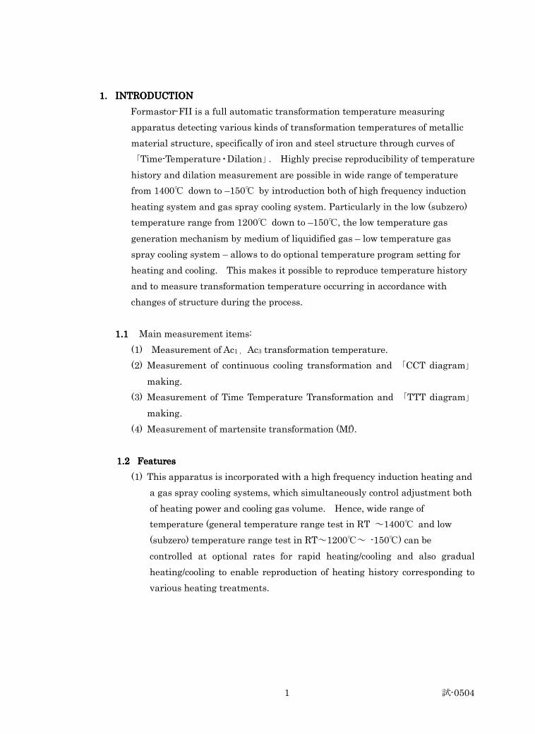
1.1.1.1. INTRODUCTIONINTRODUCTIONINTRODUCTIONINTRODUCTION
Formastor-FII is a full automatic transformation temperature measuring
apparatus detecting various kinds of transformation temperatures of metallic
material structure, specifically of iron and steel structure through curves of
「Time-Temperature・Dilation」. Highly precise reproducibility of temperature
history and dilation measurement are possible in wide range of temperature
from 1400℃ down to –150℃ by introduction both of high frequency induction
heating system and gas spray cooling system. Particularly in the low (subzero)
temperature range from 1200℃ down to –150℃, the low temperature gas
generation mechanism by medium of liquidified gas – low temperature gas
spray cooling system – allows to do optional temperature program setting for
heating and cooling. This makes it possible to reproduce temperature history
and to measure transformation temperature occurring in accordance with
changes of structure during the process.
1.11.11.11.1 Main measurement items:
(1) Measurement of Ac1 , Ac3 transformation temperature.
(2) Measurement of continuous cooling transformation and 「CCT diagram」
making.
(3) Measurement of Time Temperature Transformation and 「TTT diagram」
making.
(4) Measurement of martensite transformation (Mf).
1.21.21.21.2 Features Features Features Features
(1) This apparatus is incorporated with a high frequency induction heating and
a gas spray cooling systems, which simultaneously control adjustment both
of heating power and cooling gas volume. Hence, wide range of
temperature (general temperature range test in RT ~1400℃ and low
(subzero) temperature range test in RT~1200℃~ -150℃) can be
controlled at optional rates for rapid heating/cooling and also gradual
heating/cooling to enable reproduction of heating history corresponding to
various heating treatments.
試-0504 2
(2) Computer system enables to do integrated treatments starting with pattern
making to pattern generation = test =data collection, operational
monitoring and test = data processing of measurement results (automatic
detection of transformation temperature, CCT・TTT diagram making, etc.).
This system consists of relating hardware and software as a total system
and is very easy to operate.
(3) Detection mechanism for dilation changes occurring from transformation
is composed of low dilation material like quartz, super invar material, and
so on to avoid, to the utmost, affects from surrounding temperatures. This
makes more precise measurement
(4) In order to prevent materials from oxidation, de-carbonization and so on,
It is possible to automatically make test atmosphere condition of vacuum or
inert gas atmosphere
試-0504 3
2.2.2.2. MAIN PERFORMANCESMAIN PERFORMANCESMAIN PERFORMANCESMAIN PERFORMANCES
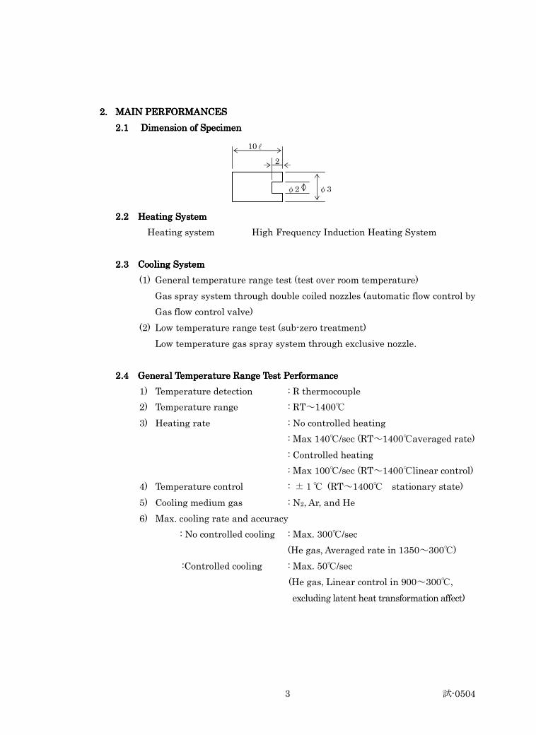
2.12.12.12.1 Dimension of Specimen Dimension of Specimen Dimension of Specimen Dimension of Specimen
2.2 Heating System2.2 Heating System2.2 Heating System2.2 Heating System
Heating system High Frequency Induction Heating System
2.3 Cooling System 2.3 Cooling System 2.3 Cooling System 2.3 Cooling System
(1) General temperature range test (test over room temperature)
Gas spray system through double coiled nozzles (automatic flow control by
Gas flow control valve)
(2) Low temperature range test (sub-zero treatment)
Low temperature gas spray system through exclusive nozzle.
2.4 General Temperature Range Test Performance2.4 General Temperature Range Test Performance2.4 General Temperature Range Test Performance2.4 General Temperature Range Test Performance
1) Temperature detection : R thermocouple
2) Temperature range : RT~1400℃
3) Heating rate : No controlled heating
: Max 140℃/sec (RT~1400℃averaged rate)
: Controlled heating
: Max 100℃/sec (RT~1400℃linear control)
4) Temperature control : ±1℃ (RT~1400℃ stationary state)
5) Cooling medium gas : N2, Ar, and He
6) Max. cooling rate and accuracy
: No controlled cooling : Max. 300℃/sec
(He gas, Averaged rate in 1350~300℃)
:Controlled cooling : Max. 50℃/sec
(He gas, Linear control in 900~300℃,
excluding latent heat transformation affect)
10 l
2
φ2 φ3
試-0504 4
2.5 Low Temperature Range Testing Performance2.5 Low Temperature Range Testing Performance2.5 Low Temperature Range Testing Performance2.5 Low Temperature Range Testing Performance
1) Temperature detection : K thermocouple
2) Temperature range : -150℃~1200℃ (continuously)
3) Heating rate (Controlled heating) : Max.50℃/sec (RT~1200℃)
4) Cooling rate : ① 100℃/sec (1200~50℃)
: ② 15℃/sec (50~-50℃)
: ③ 1.5℃/sec (-50~-100℃)
: ④ 0.8℃/sec (-100~-150℃)
5) Control accuracy : ①±1℃(RT~1200℃ stationary state)
: ②±3℃(RT~-150℃ stationary state)
6) Atmosphere : ① Vacuum, Inert gas (RT~1200℃)
: ② He Gas (Low temperature range
RT~ -150℃)
2.6 Dilation Measurement2.6 Dilation Measurement2.6 Dilation Measurement2.6 Dilation Measurement
1) Detection system : Differential transformation system
2) Measuring range : 4 ranges of;
0.5, 0.2, 0.1, 0.05mm /±5V
3) Accuracy : ±1.0% / F.S.
4) Output voltage : ±5V / F.S.
5) Stability : room temperature 1μ/4hours
sub-zero temperature 5μ/20minutes
(RT change within 5%)
2.7 Vacuum/Exhaust 2.7 Vacuum/Exhaust 2.7 Vacuum/Exhaust 2.7 Vacuum/Exhaust SystemSystemSystemSystem
1) Rotary pump : 162 (50Hz) / 197 (60 Hz) ℓ /min.
2) Diffusion pump : 360 L /sec ( Dia. 3 inches)
3) Vacuuming rate : Max. 1.3 x 10⁻² Pa / 15 min.
4) Attainable vacuum : Order of 10-3 Pa
5) Valve drive : Air drive system
試-0504 5
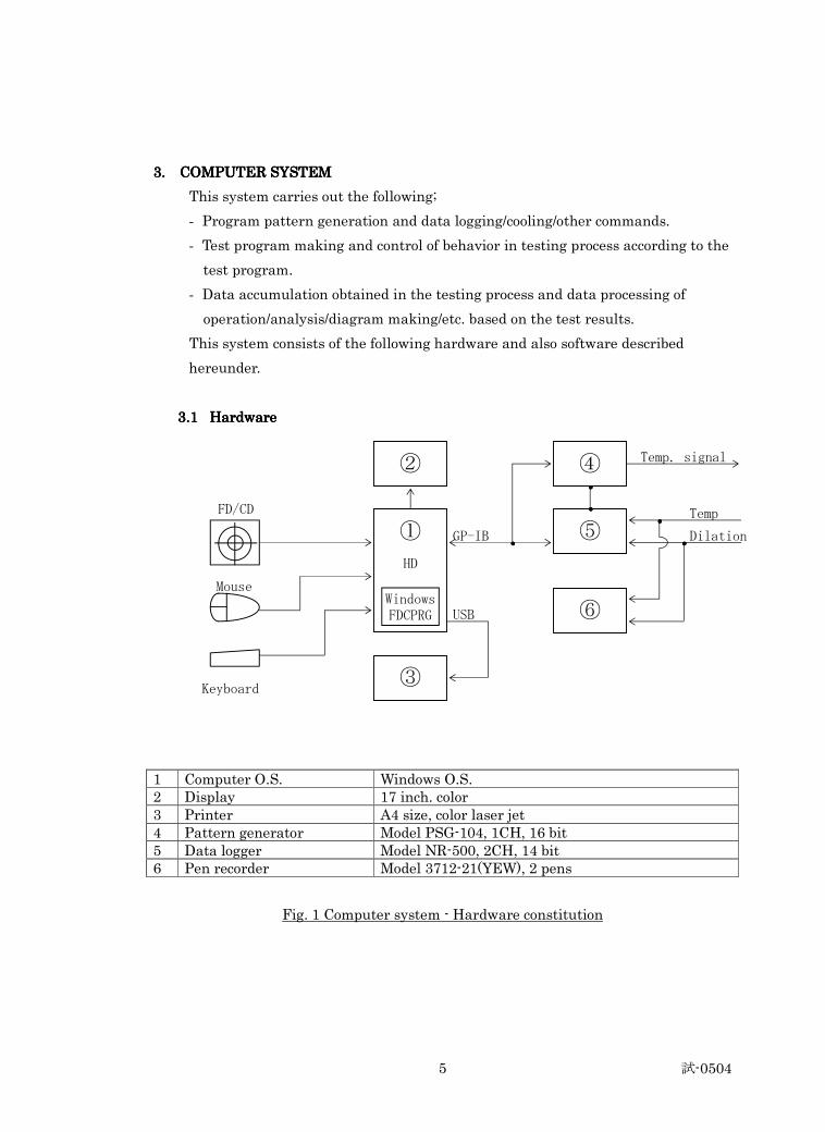
3. COMPUTER SYSTE3. COMPUTER SYSTE3. COMPUTER SYSTE3. COMPUTER SYSTEMMMM
This system carries out the following;
- Program pattern generation and data logging/cooling/other commands.
- Test program making and control of behavior in testing process according to the
test program.
- Data accumulation obtained in the testing process and data processing of
operation/analysis/diagram making/etc. based on the test results.
This system consists of the following hardware and also software described
hereunder.
3.13.13.13.1 Hardware Hardware Hardware Hardware
FD/CD
Keyboard
1 Computer O.S. Windows O.S. 2 Display 17 inch. color 3 Printer A4 size, color laser jet 4 Pattern generator Model PSG-104, 1CH, 16 bit 5 Data logger Model NR-500, 2CH, 14 bit 6 Pen recorder Model 3712-21(YEW), 2 pens
Fig. 1 Computer system - Hardware constitution
② ④
⑤
⑥
③
①
HD
Windows FDCPRG
Mouse
GP-IB
USB
Temp. signal
Temp
Dilation ・・・・
・・・・ ・・・・
・・・・ ・・・・
試-0504 6
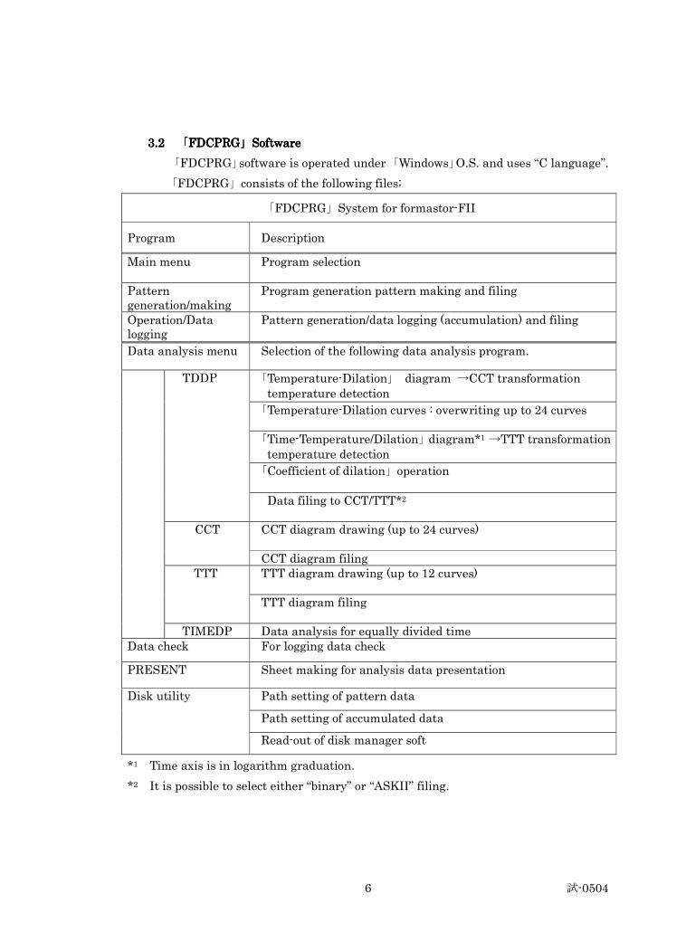
3.2 3.2 3.2 3.2 「「「「FDCPRGFDCPRGFDCPRGFDCPRG」」」」SoftwareSoftwareSoftwareSoftware
「FDCPRG」software is operated under 「Windows」O.S. and uses “C language”.
「FDCPRG」consists of the following files;
「FDCPRG」System for formastor-FII
Program Description
Main menu
Program selection
Pattern generation/making
Program generation pattern making and filing
Operation/Data logging
Pattern generation/data logging (accumulation) and filing
Data analysis menu Selection of the following data analysis program.
「Temperature-Dilation」 diagram →CCT transformation temperature detection
「Temperature-Dilation curves : overwriting up to 24 curves
「Time-Temperature/Dilation」diagram*1 →TTT transformation temperature detection
「Coefficient of dilation」operation
TDDP
Data filing to CCT/TTT*2
CCT diagram drawing (up to 24 curves) CCT
CCT diagram filing TTT diagram drawing (up to 12 curves) TTT
TTT diagram filing
TIMEDP Data analysis for equally divided time Data check For logging data check
PRESENT Sheet making for analysis data presentation
Path setting of pattern data
Path setting of accumulated data
Disk utility
Read-out of disk manager soft
*1 Time axis is in logarithm graduation.
*2 It is possible to select either “binary” or “ASKII” filing.
試-0504 7
3.3 3.3 3.3 3.3 Data ProcessingData ProcessingData ProcessingData Processing
3.3.13.3.13.3.13.3.1 TDDPTDDPTDDPTDDP
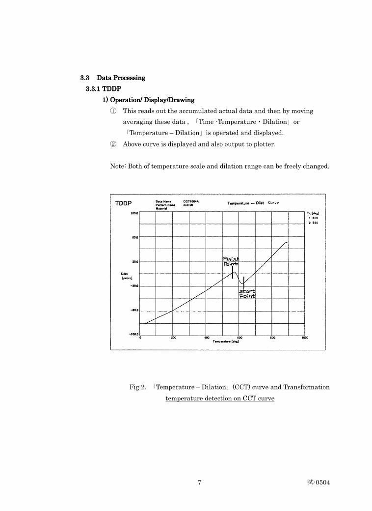
1)1)1)1) Operation/ Display/DrawingOperation/ Display/DrawingOperation/ Display/DrawingOperation/ Display/Drawing
① This reads out the accumulated actual data and then by moving
averaging these data , 「Time -Temperature・Dilation」or
「Temperature – Dilation」is operated and displayed.
② Above curve is displayed and also output to plotter.
Note: Both of temperature scale and dilation range can be freely changed.
Fig 2. 「Temperature – Dilation」(CCT) curve and Transformation
temperature detection on CCT curve
試-0504 8
2)2)2)2) Transformation Temperature DetectionTransformation Temperature DetectionTransformation Temperature DetectionTransformation Temperature Detection
Transformation temperature is detected on the curve drawn on the item
(Operation/Display/Drawing)-1)
<<<< Detection on Detection on Detection on Detection on 「「「「Temperature Temperature Temperature Temperature ---- Dilation Dilation Dilation Dilation」」」」(CCT) curve (CCT) curve (CCT) curve (CCT) curve >>>>………… Fig. Fig. Fig. Fig.2
① When “Automatic Detection” is selected, cursor is indicated. It comes
down on the curve from higher temperature side, operating gradient
and so on.
② When the transformation temperature is detected, the point is
acknowledged as the starting point of transformation. Cursor stops
at the point, which is the 「transformation temperature」.
③ “Automatic Detection” starts again, cursor simultaneously moves and
stops at the different point on the curve, which is the second
transformation point and finishing point.
④ Simultaneously, detection and registration of transformation
temperature shall be repeatedly done.
試-0504 9
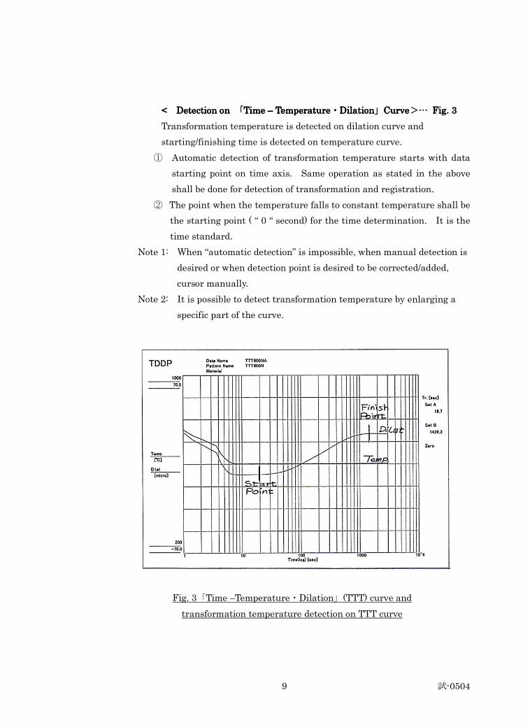
< Detection on < Detection on < Detection on < Detection on 「「「「Time Time Time Time –––– Temperature Temperature Temperature Temperature・・・・DilationDilationDilationDilation」」」」CurveCurveCurveCurve>>>>………… Fig. 3 Fig. 3 Fig. 3 Fig. 3
Transformation temperature is detected on dilation curve and
starting/finishing time is detected on temperature curve.
① Automatic detection of transformation temperature starts with data
starting point on time axis. Same operation as stated in the above
shall be done for detection of transformation and registration.
② The point when the temperature falls to constant temperature shall be
the starting point ( “ 0 “ second) for the time determination. It is the
time standard.
Note 1: When “automatic detection” is impossible, when manual detection is
desired or when detection point is desired to be corrected/added,
cursor manually.
Note 2: It is possible to detect transformation temperature by enlarging a
specific part of the curve.
Fig. 3「Time –Temperature・Dilation」(TTT) curve and
transformation temperature detection on TTT curve
試-0504 10
3) 「CCT」and 「TTT」file making
① Data that the transformation temperature is detected and registered
on「Temperature – Dilation」curve shall be saved in 「CCT」 file for
making 「CCT diagram」.
② Data that the transformation point is detected and registered on
「Time – Temperature・Dilation」curve shall be saved in 「TTT」file for
making 「TTT diagram」.
4) Operation of coefficient of linear thermal expansion Dilation coefficient
can be operated from 「Temperature – Dilation」(CCT) curve.
For this, data during heat rise process is necessary.
By inputting temperature range and step temperature, dilation
coefficient is output accordingly.
3.3.2 3.3.2 3.3.2 3.3.2 「「「「CCTCCTCCTCCT」」」」and and and and 「「「「TTTTTTTTTTTT」」」」
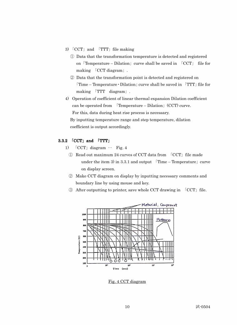
1) 「CCT」diagram … Fig. 4
① Read out maximum 24 curves of CCT data from 「CCT」file made
under the item 3) in 3.3.1 and output 「Time – Temperature」curve
on display screen.
② Make CCT diagram on display by inputting necessary comments and
boundary line by using mouse and key.
③ After outputting to printer, save whole CCT drawing in 「CCT」file.
Fig. 4 CCT diagram
試-0504 11
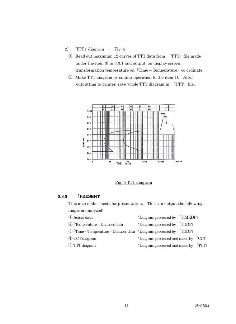
2) 「TTT」diagram … Fig. 5
① Read out maximum 12 curves of TTT data from 「TTT」file made
under the item 3) in 3.3.1 and output, on display screen,
transformation temperature on「Time – Temperature」co-ordinate.
② Make TTT diagram by similar operation to the item 1). After
outputting to printer, save whole TTT diagram in 「TTT」file.
Fig. 5 TTT diagram
3.3.33.3.33.3.33.3.3 「「「「PRESENTPRESENTPRESENTPRESENT」」」」
This is to make sheets for presentation. This can output the following
diagram analyzed;
① Actual data : Diagram processed by 「TIMEDP」
② 「Temperature – Dilation」data : Diagram processed by 「TDDP」
③ 「Time – Temperature・Dilation」data : Diagram processed by 「TDDP」
④ CCT diagram : Diagram processed and made by 「CCT」
⑤ TTT diagram : Diagram processed and made by 「TTT」
試-0504 12
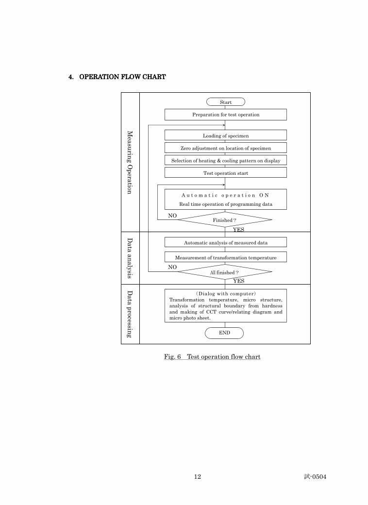
4.4.4.4. OPERATION FLOW CHART OPERATION FLOW CHART OPERATION FLOW CHART OPERATION FLOW CHART
Fig. 6 Test operation flow chart
NO
YES
NO
YES
Mea
surin
g O
pera
tion
Preparation for test operation
Start
Loading of specimen
Zero adjustment on location of specimen
Selection of heating & cooling pattern on display
Test operation start
A u t o m a t i c o p e r a t i o n O N
Real time operation of programming data
Finished?
Automatic analysis of measured data
Measurement of transformation temperature
All finished?
(Dialog with computer) Transformation temperature, micro structure, analysis of structural boundary from hardness and making of CCT curve/relating diagram and micro photo sheet.
END
Data analysis
Data processin
g
試-0504 13
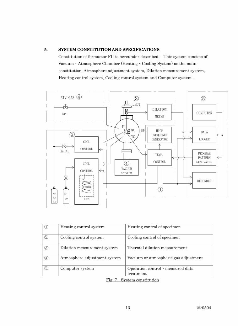
5.5.5.5. SYSTEM CONSTITUTION AND SPECIFICATIONSSYSTEM CONSTITUTION AND SPECIFICATIONSSYSTEM CONSTITUTION AND SPECIFICATIONSSYSTEM CONSTITUTION AND SPECIFICATIONS
Constitution of formastor FII is hereunder described. This system consists of
Vacuum・Atmosphere Chamber (Heating・Cooling System) as the main
constitution, Atmosphere adjustment system, Dilation measurement system,
Heating control system, Cooling control system and Computer system..
LVDT
WC HF
TC
N2 He
N2
①
Heating control system Heating control of specimen
②
Cooling control system Cooling control of specimen
③ Dilation measurement system Thermal dilation measurement
④
Atmosphere adjustment system Vacuum or atmospheric gas adjustment
⑤ Computer system Operation control・measured data treatment
Fig. 7 System constitution
DILATION
METER COMPUTER
HIGH FREQUENCE GENERATOR
TEMP.
CONTROL
DATA
LOGGER
PROGRAM PATTERN GENERATOR
RECORDER
④ VACUUM SYSTEM
COOL
CONTROL
LN2
③ ⑤
①
ATM GAS ④
TP
・・・・
・・・・
・・・・
・・・・ ・・・・
Ar
He
He,N2
Ar
②
COOL
CONTROL
LN2
試-0504 14
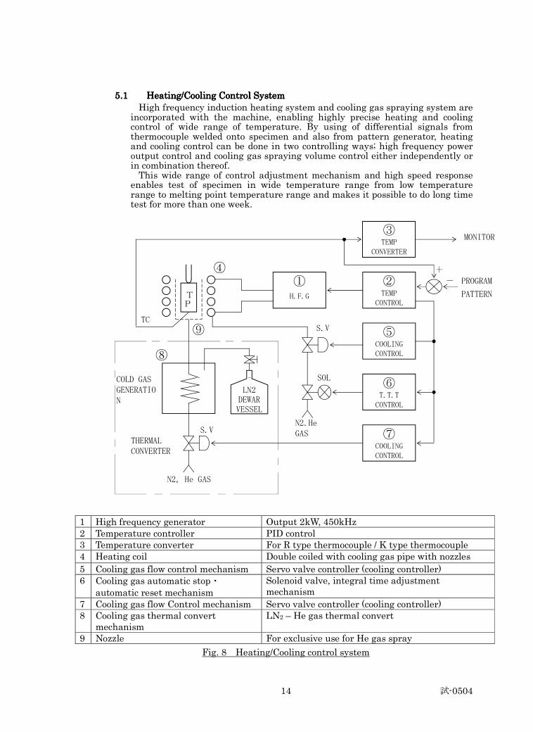
5.15.15.15.1 Heating/Cooling Control System Heating/Cooling Control System Heating/Cooling Control System Heating/Cooling Control System High frequency induction heating system and cooling gas spraying system are incorporated with the machine, enabling highly precise heating and cooling control of wide range of temperature. By using of differential signals from thermocouple welded onto specimen and also from pattern generator, heating and cooling control can be done in two controlling ways; high frequency power output control and cooling gas spraying volume control either independently or in combination thereof. This wide range of control adjustment mechanism and high speed response enables test of specimen in wide temperature range from low temperature range to melting point temperature range and makes it possible to do long time test for more than one week.
TC
SOL
N2, He GAS
1 High frequency generator Output 2kW, 450kHz 2 Temperature controller PID control 3 Temperature converter For R type thermocouple / K type thermocouple 4 Heating coil Double coiled with cooling gas pipe with nozzles
5 Cooling gas flow control mechanism Servo valve controller (cooling controller) 6
Cooling gas automatic stop・ automatic reset mechanism
Solenoid valve, integral time adjustment mechanism
7 Cooling gas flow Control mechanism Servo valve controller (cooling controller) 8 Cooling gas thermal convert
mechanism LN2 – He gas thermal convert
9 Nozzle For exclusive use for He gas spray
Fig. 8 Heating/Cooling control system
③ TEMP
CONVERTER
② TEMP
CONTROL
⑤ COOLING CONTROL
⑥ T.T.T CONTROL
⑦ COOLING CONTROL
① H.F.G
LN2 DEWAR VESSEL
THERMAL CONVERTER
S.V
-
TP
N2.He GAS
S.V
⑧
⑨
④ +
PROGRAM
PATTERN
MONITOR
COLD GAS GENERATION
試-0504 15
5.1.1.15.1.1.15.1.1.15.1.1.1 High Frequency GeneratorHigh Frequency GeneratorHigh Frequency GeneratorHigh Frequency Generator
1) Oscillation method : Colpitts method
2) Output : 2 kW
3) Frequency : 450kHz ± 10%
4) Output control : Duty control (PWM)
5) Output range : 0~100% / 0~5V
6) Oscillation bulb : 6T58RA
7) Power supply : 3φ 200V 3.5kVA
8) Cooling water : 8 l /min. 0.25~0.35Moa ( 2.5~3.5kgf/cm2)
Back pressure 0.05Mpa ( 0.5kgf / cm2)
9) Protection circuit : ① Over current relay
: ② Water shut-off relay
5.1.25.1.25.1.25.1.2 Temperature ControllerTemperature ControllerTemperature ControllerTemperature Controller
1) Control method : PID operation method
2) Setting input : ① 0~4V / 0~1600℃ (R thermocouple)
: ② -0.375~3V / -150~1200℃ (K thermocouple)
3) Thermocouple input : ① 0~16mV / 0~1600℃ ( R thermocouple)
: ② -1.5~12mV / -150~1200℃ (K thermocouple)
4) Output signal : ① 0~5V / 0~100% ( heating signal)
: ② ±10V / ±100% ( cooling signal)
5) Control accuracy : ① General temperature range test: ±1℃
: ② Low temperature range test :
in general temperature range ±1℃
in low temperature range ±5℃
6) Temperature indication : 3-1/2 figures Digital indication
( actual/differential measurement)
7) Protection circuit : Temperature differential limit ( ±100℃)
試-0504 16
5.1.35.1.35.1.35.1.3 Temperature ConverterTemperature ConverterTemperature ConverterTemperature Converter
2 different kinds of converter are prepared for general temperature range
test and for low temperature range test separately. These are used for
input of signal to temperature monitor and also data logger.
< For General Temperature Range Test = Using< For General Temperature Range Test = Using< For General Temperature Range Test = Using< For General Temperature Range Test = Using「「「「RRRR」」」」Thermocouple >Thermocouple >Thermocouple >Thermocouple >
1) Model : MS-3701-R
2) Input signal : 0~18.74mV / 0~1600℃
3) Output signal : 0~16mV / 0~1600℃ (linear)
4) Accuracy : ± ( 0.1%FS + 0.3℃ linearize accuracy)
5) Response Speed : 100Hz
6) Protection Circuit : UP Burnout
< Low Temperature Range Test = Using< Low Temperature Range Test = Using< Low Temperature Range Test = Using< Low Temperature Range Test = Using「「「「KKKK」」」」Thermocouple >Thermocouple >Thermocouple >Thermocouple >
7) Model : MS-3701-K
8) Input signal : -3.64~48.94mV / -150~1200℃
9) Output signal : -1.5~12mV / -150~1200℃ (linear)
10) Accuracy : ± (0.1%FS +0.3℃ linerize accuracy)
11) Response Speed : 100Hz
12) Protection Circuit : UP Burnout
5.1.45.1.45.1.45.1.4 Cooling ControllerCooling ControllerCooling ControllerCooling Controller
2 different kinds of cooling control circuits are prepared in 2 series;
one for controlled cooling and the other for rapid cooling. In order to do the
test in low temperature range, thermal converter is set in cooling circuit to
reduce He gas temperature to less than zero centigrade for spraying onto
specimen. This is for making heat history in sub-zero treatment.
< Common >< Common >< Common >< Common >
1) Cooling method : General temperature range
Gas spray from nozzles on inner coil
: Low temperature range
Gas spray from independent/exclusive nozzles
2) Cooling signal : Time signal ON/OFF signal from pattern
generator
試-0504 17
3) Cooling gas : General temperature range:
N2, He Max. 0.7Mpa, 200 ℓ /min.
:Low temperature range
He Max. 0.7Mpa 200 ℓ /min.
LN2 Max. 10 ℓ (DEWAR VESSEL Volume)
< Controlled Cooling Circuit >< Controlled Cooling Circuit >< Controlled Cooling Circuit >< Controlled Cooling Circuit >
1) Control method : PID operation method
2) Control object : Gas flow 0~ 70 ℓ /min.
3) Input signal : Temperature differential signal ±10V / ±200℃
4) Output signal : Signal to servo valve ±100mA /±100%
5) Monitor : ±100mA Analog Meter
6) Valve : Servo valve 58A
< Rapid Cooling Circuit >< Rapid Cooling Circuit >< Rapid Cooling Circuit >< Rapid Cooling Circuit >
1) Control method : 2 position ( ON/OFF ) control
2) Valve : Solenoid valve AC200V
Note: This mechanism prevents overshoot (undershoot) at the time of abrupt
temperature change to stationary state in T.T.T. program and allows
to reach desired temperature (constant temperature) in a short time.
< Cooling Stop Mechanism >< Cooling Stop Mechanism >< Cooling Stop Mechanism >< Cooling Stop Mechanism >
Cooling valve should be turned to “CLOSE” at the temperature set for a
target temperature.
1) Cooling stop setting method: Temperature differential setting method
by dial
2) Temperature differential setting range: 0~200℃ for target temperature
< Auto Reset Mechanism >< Auto Reset Mechanism >< Auto Reset Mechanism >< Auto Reset Mechanism >
This is a mechanism rapidly to attain the target temperature, decreasing
unnecessary time by altering integrating time.
1) Reset setting method: Time differential setting method by dial
2) Temperature differential setting range: 0~100℃ for target
試-0504 18
SPECIMEN
HEATING COIL
THERMO COUPLE
TO RECORDER
DATA LOGGER
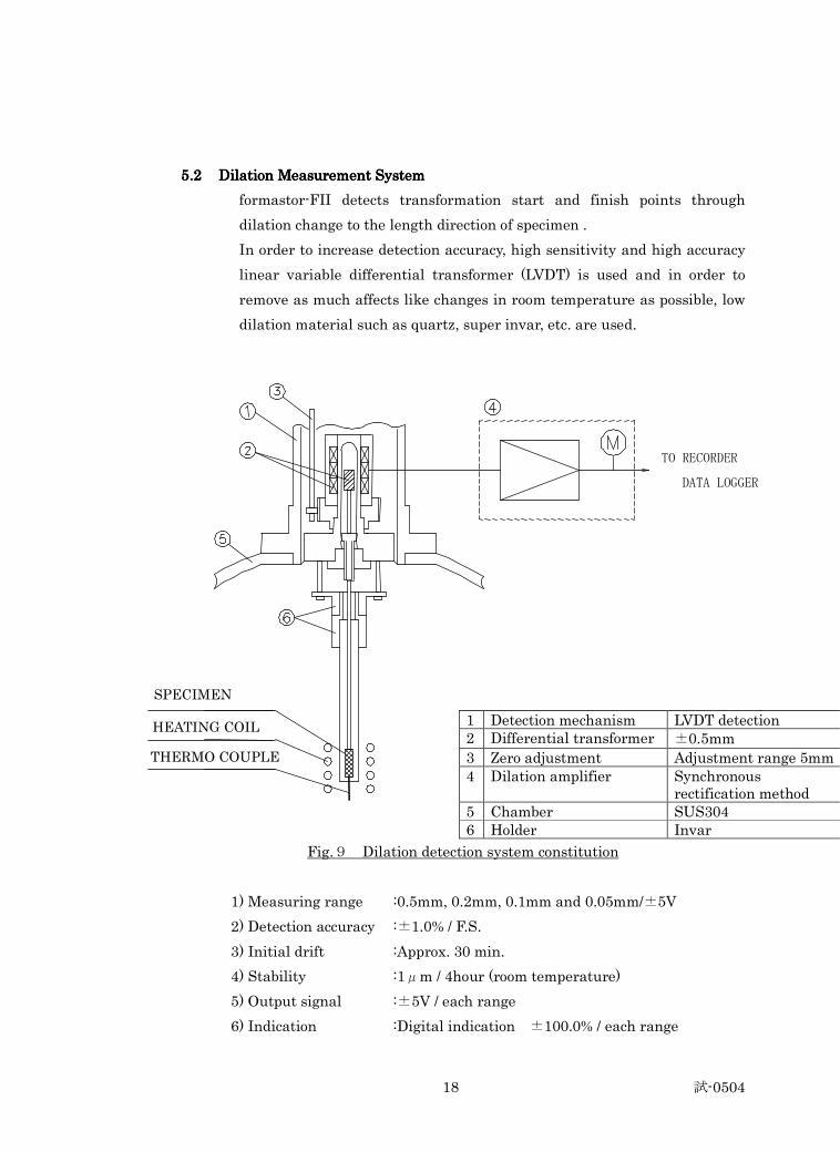
5.2 5.2 5.2 5.2 Dilation Measurement System Dilation Measurement System Dilation Measurement System Dilation Measurement System
formastor-FII detects transformation start and finish points through
dilation change to the length direction of specimen .
In order to increase detection accuracy, high sensitivity and high accuracy
linear variable differential transformer (LVDT) is used and in order to
remove as much affects like changes in room temperature as possible, low
dilation material such as quartz, super invar, etc. are used.
1 Detection mechanism LVDT detection 2 Differential transformer ±0.5mm
3 Zero adjustment Adjustment range 5mm 4
Dilation amplifier Synchronous rectification method
5 Chamber SUS304 6 Holder Invar
Fig.9 Dilation detection system constitution
1) Measuring range :0.5mm, 0.2mm, 0.1mm and 0.05mm/±5V
2) Detection accuracy :±1.0% / F.S.
3) Initial drift :Approx. 30 min.
4) Stability :1μm / 4hour (room temperature)
5) Output signal :±5V / each range
6) Indication :Digital indication ±100.0% / each range
試-0504 19
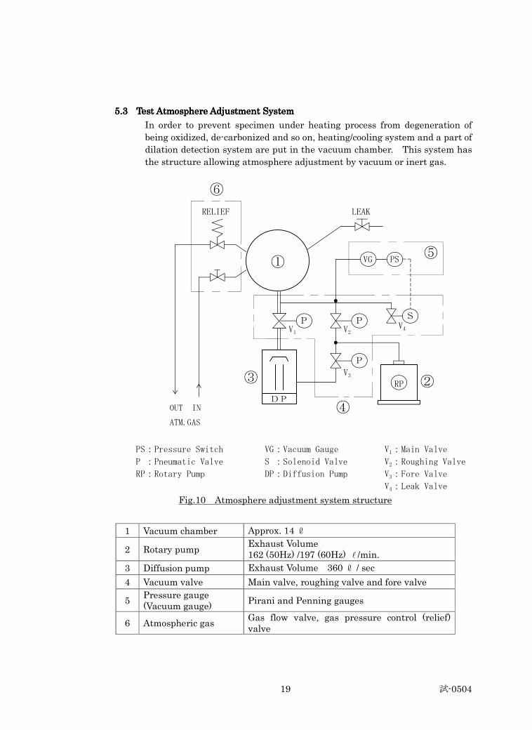
5.35.35.35.3 Test Atmosphere Adjustment SystemTest Atmosphere Adjustment SystemTest Atmosphere Adjustment SystemTest Atmosphere Adjustment System
In order to prevent specimen under heating process from degeneration of
being oxidized, de-carbonized and so on, heating/cooling system and a part of
dilation detection system are put in the vacuum chamber. This system has
the structure allowing atmosphere adjustment by vacuum or inert gas.
OUT IN
ATM.GAS
PS:Pressure Switch VG:Vacuum Gauge V1:Main Valve
P :Pneumatic Valve S :Solenoid Valve V2:Roughing Valve
RP:Rotary Pump DP:Diffusion Pump V3:Fore Valve
V4:Leak Valve
Fig.10 Atmosphere adjustment system structure
1 Vacuum chamber Approx. 14 ℓ
2 Rotary pump Exhaust Volume 162 (50Hz) /197 (60Hz) l /min.
3 Diffusion pump Exhaust Volume 360 ℓ / sec
4 Vacuum valve Main valve, roughing valve and fore valve
5 Pressure gauge (Vacuum gauge)
Pirani and Penning gauges
6 Atmospheric gas Gas flow valve, gas pressure control (relief) valve
①
DP
RP
P
P P S
VG
LEAK RELIEF
⑥
⑤
② ③
④
V4 V2 V1
V3
PS
試-0504 20
5.3.15.3.15.3.15.3.1 ChamberChamberChamberChamber
1) Material : SUS304
2) Size : φ300 x D200
3) Port : ① cooling and atmospheric gas induction port
: ② leak gas exhaust port
: ③ Gauge port
: ④ Thermocouple port
: : : : ⑤ High frequency induction lead-through port
: : : : ⑥ Dilation detection port
4) Observation window : φ50
5) Protector : ⑦ Door switch
5.3.25.3.25.3.25.3.2 Rotary PumpRotary PumpRotary PumpRotary Pump
1) Model : RV8
2) Exhaust rate : 162 (50Hz) / 197 (60Hz) ℓ /min.
3 ) Attainable pressure : 1.3 x 10⁻¹Pa order
4) Oil volume : 750 cc
5) Motor : 3φ 200V 450W (50Hz) / 550W (60Hz)
6) Protection Circuit : Auto-leak
5.35.35.35.3.3.3.3.3 Diffusion PumpDiffusion PumpDiffusion PumpDiffusion Pump
1) Model : DSS-321 (DPF-3Z 3 inch)
2) Exhaust rate : 360 ℓ / sec
3) Attainable pressure : 1.3 x 10⁻⁴Pa
4) Oil volume : 100 cc
5) Heater : 1φ 200V 500W
6) Cooling water : 2 ℓ /min. 0.25Mpa (2.5kgf / cm2)
7) Protection Circuit : ① Flow switch
: ② Over-heat
試-0504 21
5.3.45.3.45.3.45.3.4 ValveValveValveValve
1) Method : Pneumatic method
2) Air pressure : 0.4Mpa (4kg/cm2)
3) Main valve : 3 inch butterfly valve
4) Rough/Back valve : 1 inch 3way valve
5) Leak valve : 3/8 inch solenoid valve
6) Protection circuit : ① Air pressure detection
: ② Main valve open/close LS
: ③ Rough/Back valve open LS
5.3.55.3.55.3.55.3.5 Vacuum GaugeVacuum GaugeVacuum GaugeVacuum Gauge
<Pressure switch <Pressure switch <Pressure switch <Pressure switch –––– Digital Indication> Digital Indication> Digital Indication> Digital Indication>
1) Model : PIS-PO1K
2) Measuring pressure : 0~ 0.1 MPa
3) Contact : 0.01MPa
<Pirani gauge><Pirani gauge><Pirani gauge><Pirani gauge>
1) Model : ① Sensor P-3
: ② Amplifier VS-10P
2) Measuring pressure : 102 ~10-1Pa
3) Contact : 10Pa
<Penning gauge><Penning gauge><Penning gauge><Penning gauge>
1) Model : ① Sensor C-1
: ② Amplifier VS-5P
2) Measuring pressure : 10-1 ~10-4 Pa (ON)
3) Contact : 1.3 x 10⁻²Pa
5.3.6 Atmospheric Gas Relations5.3.6 Atmospheric Gas Relations5.3.6 Atmospheric Gas Relations5.3.6 Atmospheric Gas Relations
1) Atmospheric gas : Inert gas ( Ar, N2 )
2) Gas flow-through valve : 1/4 inch solenoid valve
3) Gas exhaust valve : 1/4 inch valve
試-0504 22
5.45.45.45.4 Computer System Computer System Computer System Computer System
This system consists of DOS/V and the “Windows” OS type computer as the
main items, Display, Printer connected with RS-232C, Pattern generator
and Data logger controlled by GP-IB.
5.4.15.4.15.4.15.4.1 ComputerComputerComputerComputer
1) Model : * Optiplex GX755(DELL)
2) C P U : * Pentium 4
3) Memory : 512 MB
4) Memory equipment : ① Floppy Disk 3.5 inch
: ② Hard Disk * GB
: ③ CD R/W 12X / 8X / 32X
5) O. S. : Windows * XP
6) Interface : USB, RS-232C, GP-IB
5.4.25.4.25.4.25.4.2 Display ( Separate Setting)Display ( Separate Setting)Display ( Separate Setting)Display ( Separate Setting)
1) Model : * E178WFP (DELL)
2) Size : 17 inch Color
3) Control : Brightness/contrast/size/position
5.4.35.4.35.4.35.4.3 Printer ( Separate Setting)Printer ( Separate Setting)Printer ( Separate Setting)Printer ( Separate Setting)
1) Model :* CLJ3600 (HP)
2) Printing method : laser Jet Method
3) Resolution : 3600 dot/inch *
4) Printing rate : 16 sheets / min: color *
Note: * mark stands for model no., function, item, etc. available at the time of
discussion and/or contract.
試-0504 23
5.4.5.4.5.4.5.4.4444 Pattern GeneratorPattern GeneratorPattern GeneratorPattern Generator
1) Model : PSG-104 ( 1 channel Pattern generator)
2) Programming method : Program transfer from computer
3) Channel : 1 (Temperature)
4) Address : 99 points
5) Time setting : ( 1~9999 sec) x 1/100, 1/10, 1 and 10
6) Temperature setting : -200~1600℃ 1℃ step
7) Controlled signal : 8 series (RT1~RT8)
8) Controlled signal setting : 1 / series / each address
9) Output voltage : –0.5~4v
10) Output voltage accuracy : ±0.1% (16 bits)
11) Output time accuracy : ±0.1 sec at “ x 1 “ magnification
12) Interface : GP-IB
5.4.5.4.5.4.5.4.5555 Data LoggerData LoggerData LoggerData Logger
1) Model : NR-500 ( 4 channel data logger )
2) Channel : ① 1 ch ( Temperature )
: ② 2 ch ( Dilation )
Note : 3 and 4ch are for spare use.
3) Resolution : 14 bits
4) Input signal : ① 1ch (Temperature) 0~5V/ 0~1600℃
: ② 2 ch (Dilation) ±5V/±100%
5) Sampling time : 1μs~60s
6) Accuracy : DC volt 0.1% of F.S
7) Interface : USB (Ver 1.0)
8) Accessory : AC adapter, USB cable
試-0504 24
5.55.55.55.5 RecorderRecorderRecorderRecorder
1) Model : 3712-21 (YEW)
2) Pen : 2 pens (red and green)
& signal Temperature and dilation
3) Recording paper width : 250mm
4) Accuracy : ±0.25% / recording paper width
5) Pen rate : 1600mm/sec
6) measuring range : Direct current (DCV) 10mV~200V F.S.
7) Recording paper : Folding type approx. 20m (DIN chart)
8) Chart speed : 10~1200mm/min and mm/hour
9) Remote function : Pen up・down
Chart start, stop
Chart speed 2 kinds
試-0504 25
6.6.6.6. SafetySafetySafetySafety Protection Mechanism Protection Mechanism Protection Mechanism Protection Mechanism
In order to secure safety and protection of the system during operation,
following safety/protection mechanism are incorporated.
6.16.16.16.1 Countermeasure for Electricity Service Interruption>Countermeasure for Electricity Service Interruption>Countermeasure for Electricity Service Interruption>Countermeasure for Electricity Service Interruption>
1) Oscillation, heating and cooling stoppage
2) Exhausting system shut down
3) Prevention of rotary pump oil from adverse flow
6.26.26.26.2 Countermeasure for Cooling Water FailureCountermeasure for Cooling Water FailureCountermeasure for Cooling Water FailureCountermeasure for Cooling Water Failure
1) Oscillation・heating stoppage
2) Diffusion pump shut down
6.36.36.36.3 Countermeasure for Pressure Rise in ChamberCountermeasure for Pressure Rise in ChamberCountermeasure for Pressure Rise in ChamberCountermeasure for Pressure Rise in Chamber
When pressure in chamber should rise over specified setting point during
cooling, safety valve (pressure control valve) opens to discharge gas and
prevents abnormal pressure rise.
6.46.46.46.4 Countermeasure for OscillationCountermeasure for OscillationCountermeasure for OscillationCountermeasure for Oscillation・・・・Heating ProblemsHeating ProblemsHeating ProblemsHeating Problems
Alarm indications are on for problems during oscillating and heating. When
the followings should happen, heating immediately stops.
1) Chamber door opens.
2) Current is over rated current.
3) Either cooling water supply stops or is less than specified requirement.
4) Abnormal situation happens with vacuum/exhaust relations.
5) Temperature differential limit starts working.
6) Operation finishes as programmed.
試-0504 26
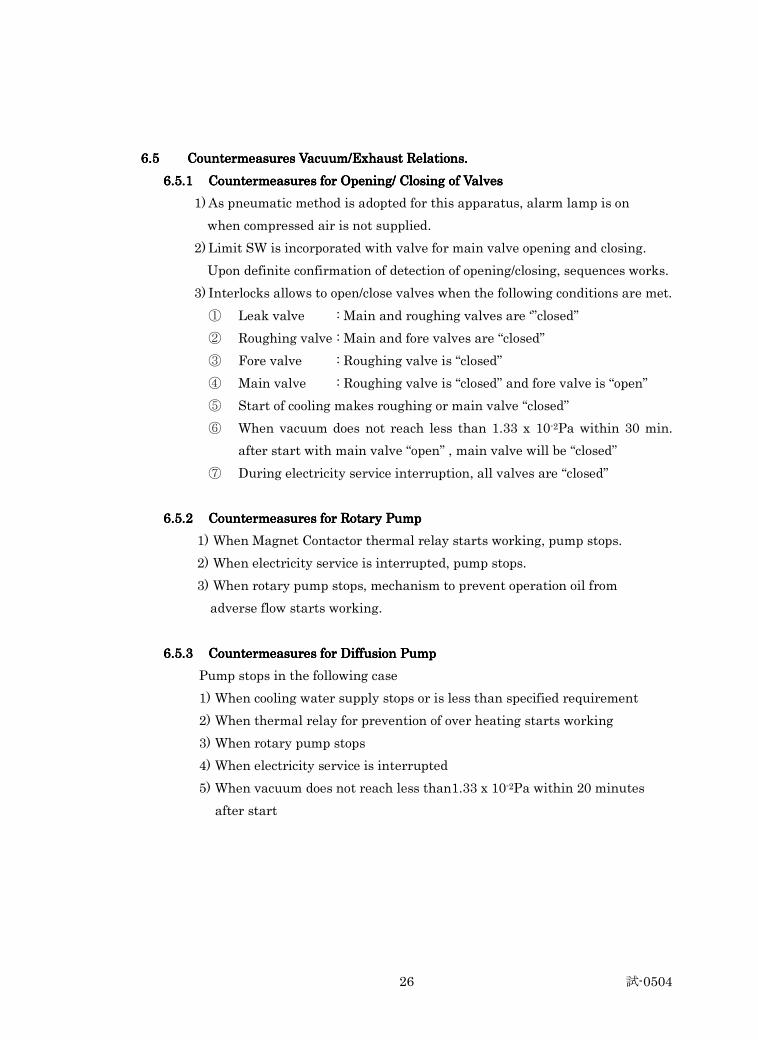
6.56.56.56.5 Countermeasures Vacuum/Exhaust Relations.Countermeasures Vacuum/Exhaust Relations.Countermeasures Vacuum/Exhaust Relations.Countermeasures Vacuum/Exhaust Relations.
6.5.16.5.16.5.16.5.1 Countermeasures for Opening/ Closing of ValvesCountermeasures for Opening/ Closing of ValvesCountermeasures for Opening/ Closing of ValvesCountermeasures for Opening/ Closing of Valves
1) As pneumatic method is adopted for this apparatus, alarm lamp is on
when compressed air is not supplied.
2) Limit SW is incorporated with valve for main valve opening and closing.
Upon definite confirmation of detection of opening/closing, sequences works.
3) Interlocks allows to open/close valves when the following conditions are met.
① Leak valve : Main and roughing valves are ‘”closed”
② Roughing valve : Main and fore valves are “closed”
③ Fore valve : Roughing valve is “closed”
④ Main valve : Roughing valve is “closed” and fore valve is “open”
⑤ Start of cooling makes roughing or main valve “closed”
⑥ When vacuum does not reach less than 1.33 x 10⁻²Pa within 30 min.
after start with main valve “open” , main valve will be “closed”
⑦ During electricity service interruption, all valves are “closed”
6.5.26.5.26.5.26.5.2 Countermeasures for Rotary Pump Countermeasures for Rotary Pump Countermeasures for Rotary Pump Countermeasures for Rotary Pump
1) When Magnet Contactor thermal relay starts working, pump stops.
2) When electricity service is interrupted, pump stops.
3) When rotary pump stops, mechanism to prevent operation oil from
adverse flow starts working.
6.5.36.5.36.5.36.5.3 Countermeasures for Diffusion PumpCountermeasures for Diffusion PumpCountermeasures for Diffusion PumpCountermeasures for Diffusion Pump
Pump stops in the following case
1) When cooling water supply stops or is less than specified requirement
2) When thermal relay for prevention of over heating starts working
3) When rotary pump stops
4) When electricity service is interrupted
5) When vacuum does not reach less than1.33 x 10-2Pa within 20 minutes
after start
試-0504 27
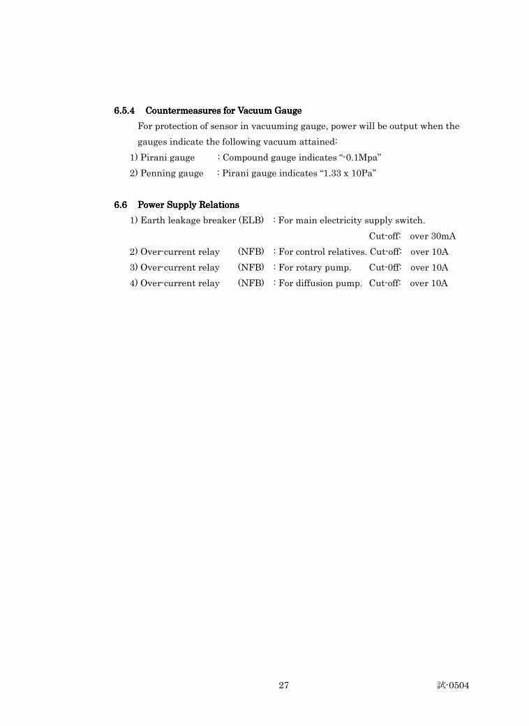
6.5.4 6.5.4 6.5.4 6.5.4 Countermeasures for Vacuum GaugeCountermeasures for Vacuum GaugeCountermeasures for Vacuum GaugeCountermeasures for Vacuum Gauge
For protection of sensor in vacuuming gauge, power will be output when the
gauges indicate the following vacuum attained:
1) Pirani gauge : Compound gauge indicates “-0.1Mpa”
2) Penning gauge : Pirani gauge indicates “1.33 x 10Pa”
6.66.66.66.6 Power Supply RelationsPower Supply RelationsPower Supply RelationsPower Supply Relations
1) Earth leakage breaker (ELB) : For main electricity supply switch.
Cut-off: over 30mA
2) Over-current relay (NFB) : For control relatives. Cut-off: over 10A
3) Over-current relay (NFB) : For rotary pump. Cut-0ff: over 10A
4) Over-current relay (NFB) : For diffusion pump. Cut-off: over 10A
試-0504 28
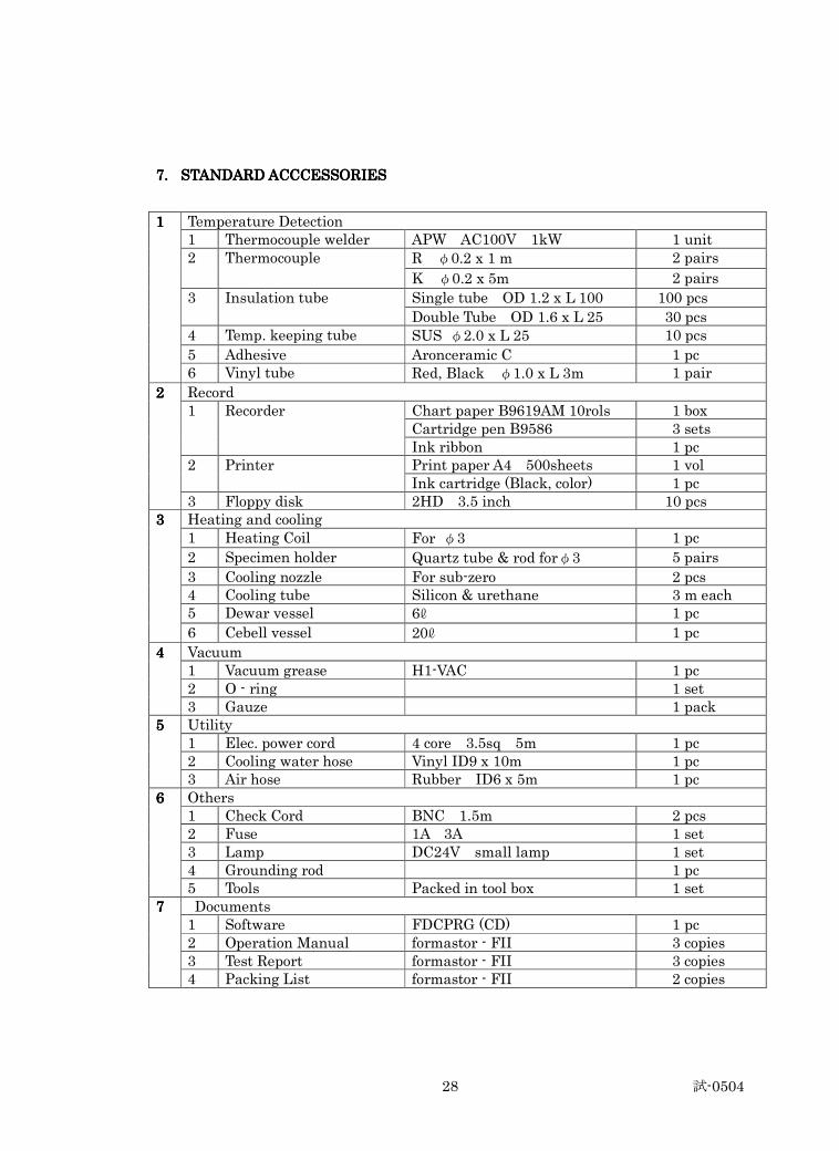
7.7.7.7. STANDSTANDSTANDSTANDARD ACCCESSORIESARD ACCCESSORIESARD ACCCESSORIESARD ACCCESSORIES
Temperature Detection 1 Thermocouple welder APW AC100V 1kW 1 unit
R φ0.2 x 1 m 2 pairs 2 Thermocouple
K φ0.2 x 5m 2 pairs
Single tube OD 1.2 x L 100 100 pcs 3 Insulation tube
Double Tube OD 1.6 x L 25 30 pcs 4 Temp. keeping tube SUS φ2.0 x L 25 10 pcs
5 Adhesive Aronceramic C 1 pc
1111
6 Vinyl tube Red, Black φ1.0 x L 3m 1 pair
Record Chart paper B9619AM 10rols 1 box Cartridge pen B9586 3 sets
1 Recorder
Ink ribbon 1 pc Print paper A4 500sheets 1 vol 2 Printer Ink cartridge (Black, color) 1 pc
2222
3 Floppy disk 2HD 3.5 inch 10 pcs Heating and cooling 1 Heating Coil For φ3 1 pc
2 Specimen holder Quartz tube & rod forφ3 5 pairs
3 Cooling nozzle For sub-zero 2 pcs 4 Cooling tube Silicon & urethane 3 m each 5 Dewar vessel 6ℓ 1 pc
3333
6 Cebell vessel 20ℓ 1 pc
Vacuum 1 Vacuum grease H1-VAC 1 pc 2 O - ring 1 set
4444
3 Gauze 1 pack Utility 1 Elec. power cord 4 core 3.5sq 5m 1 pc 2 Cooling water hose Vinyl ID9 x 10m 1 pc
5555
3 Air hose Rubber ID6 x 5m 1 pc Others 1 Check Cord BNC 1.5m 2 pcs 2 Fuse 1A 3A 1 set 3 Lamp DC24V small lamp 1 set 4 Grounding rod 1 pc
6666
5 Tools Packed in tool box 1 set Documents 1 Software FDCPRG (CD) 1 pc 2 Operation Manual formastor - FII 3 copies 3 Test Report formastor - FII 3 copies
7777
4 Packing List formastor - FII 2 copies

試-0504 29
8.8.8.8. ADDITIONAL SPARE PARTSADDITIONAL SPARE PARTSADDITIONAL SPARE PARTSADDITIONAL SPARE PARTS
1) Cooling water supply unit : add 1set
2) Step down transformer : add 1set
試-0504 30
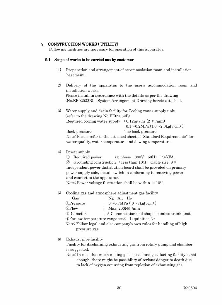
9.9.9.9. CONSTRUCTION WORKS ( UTILITY)CONSTRUCTION WORKS ( UTILITY)CONSTRUCTION WORKS ( UTILITY)CONSTRUCTION WORKS ( UTILITY)
Following facilities are necessary for operation of this apparatus.
9999.1 Scope of works to be carried out by customer.1 Scope of works to be carried out by customer.1 Scope of works to be carried out by customer.1 Scope of works to be carried out by customer
1) Preparation and arrangement of accommodation room and installation
basement.
2) Delivery of the apparatus to the user’s accommodation room and
installation works.
Please install in accordance with the details as per the drawing
(No.EE02032B) – System Arrangement Drawing hereto attached.
3) Water supply and drain facility for Cooling water supply unit
(refer to the drawing No.EE02032B)
Required cooling water supply : 0.12m3 / hr (2 ℓ /min)
0.1~0.2MPa (1.0~2.0kgf / cm2 )
Back pressure : no back pressure
Note: Please refer to the attached sheet of “Standard Requirements” for
water quality, water temperature and dewing temperature.
4) Power supply
① Required power : 3 phase 380V 50Hz 7.5kVA
② Grounding construction : less than 10Ω Cable size: 8 sq
Independent power distribution board shall be provided on primary
power supply side, install switch in conforming to receiving power
and connect to the apparatus.
Note: Power voltage fluctuation shall be within ±10%.
5) Cooling gas and atmosphere adjustment gas facility
Gas : N2, Ar, He
①Pressure : 0~0.7MPa ( 0~7kgf /cm2 )
②Flow : Max. 200Nℓ /min
③Diameter : φ7 connection end shape: bamboo trunk knot
④For low temperature range test: Liquidities N2
Note: Follow legal and also company’s own rules for handling of high
pressure gas.
6) Exhaust pipe facility
Facility for discharging exhausting gas from rotary pump and chamber
is suggested.
Note: In case that much cooling gas is used and gas ducting facility is not
enough, there might be possibility of serious danger to death due
to lack of oxygen occurring from repletion of exhausting gas
試-0504 31
10.10.10.10. GENERAL MATTERSGENERAL MATTERSGENERAL MATTERSGENERAL MATTERS
10101010.1 Warranty.1 Warranty.1 Warranty.1 Warranty
The guarantee period is 12 months after signing the Final Acceptance Report.
During the guarantee period,
A. The Buyer will bear the expenses of replacing and mailing items and
sending technicians for maintenance provided that the product is
improperly operated by the Buyer.
B. The Seller agrees to be responsible for whole – life maintenance of the
equipment. The seller shall reply within 48 hours (by telephone, email, fax
or through Mr. Wang Daoyuan) after receiving notice from the Buyer for
any problems happened after acceptance.
10101010.2 Dispatch of .2 Dispatch of .2 Dispatch of .2 Dispatch of engineer(s) to the userengineer(s) to the userengineer(s) to the userengineer(s) to the user
The manufacturer will dispatch engineer(s) to the user’s premises at the time
of apparatus delivery to the user for instructions for delivery to the operating
premises and installation as well as instructions for setting/commissioning,
test operation, training of user’s operators including handling of the
apparatus. All expenses necessary for this shall be paid by the user.
10101010.3 Documents to be submitted to the user.3 Documents to be submitted to the user.3 Documents to be submitted to the user.3 Documents to be submitted to the user
Following documents (English) will be submitted to the user;
1) Operation test report : 3 copies
2) Operation manual : 3 copies
3) Packing list : 2 copies
10101010.4 Environment conditions for operation.4 Environment conditions for operation.4 Environment conditions for operation.4 Environment conditions for operation
As the apparatus is precision machine, the user shall pay attention to the
following environmental conditions.
1) Installation site : In a building room, clean and no dust place.
Exposure direct to the sun shall be avoided.
2) Environmental temperature : 10℃~40℃
3) Environmental moisture : less than 75% RH, no dew drop.
4) Sea level height : lower than 1000m