Embed Size (px)
Citation preview
Meteor Radar SDR Receiver (FUNcube Dongle)
© Dr David Morgan 2011 Page 1
1 Introduction This article describes recent experiments with the software defined radio equipment known as the FUNcube Dongle (FCD)1 to determine its usefulness as the receiver in a Meteor Scatter Radar. For details of the FCD see Appendix A The radar uses the Graves French space surveillance transmitter2 located near Dijon, operating on a frequency of 143.050MHz. The experiments reported here were to determine if the FCD was capable of receiving the weak backscatter echoes from meteors in the presence of much larger locally transmitted signals such as 2m amateur radio and pagers. The work was conducted with a commercial 140MHz low pass filter in place to eliminate some strong signals above this frequency. No high Q bandpass filter was available during these tests to minimise nearby signals, however it is planned to carry out more work when such a filter has been constructed. The results presented here therefore can probably be improved upon. As the article will show, a fair degree of success was achieved in detecting meteors during the Draconid Meteor shower3 on the 8th and 9th of October 2011.
Meteor Radar SDR Receiver (FUNcube Dongle)
© Dr David Morgan 2011 Page 2
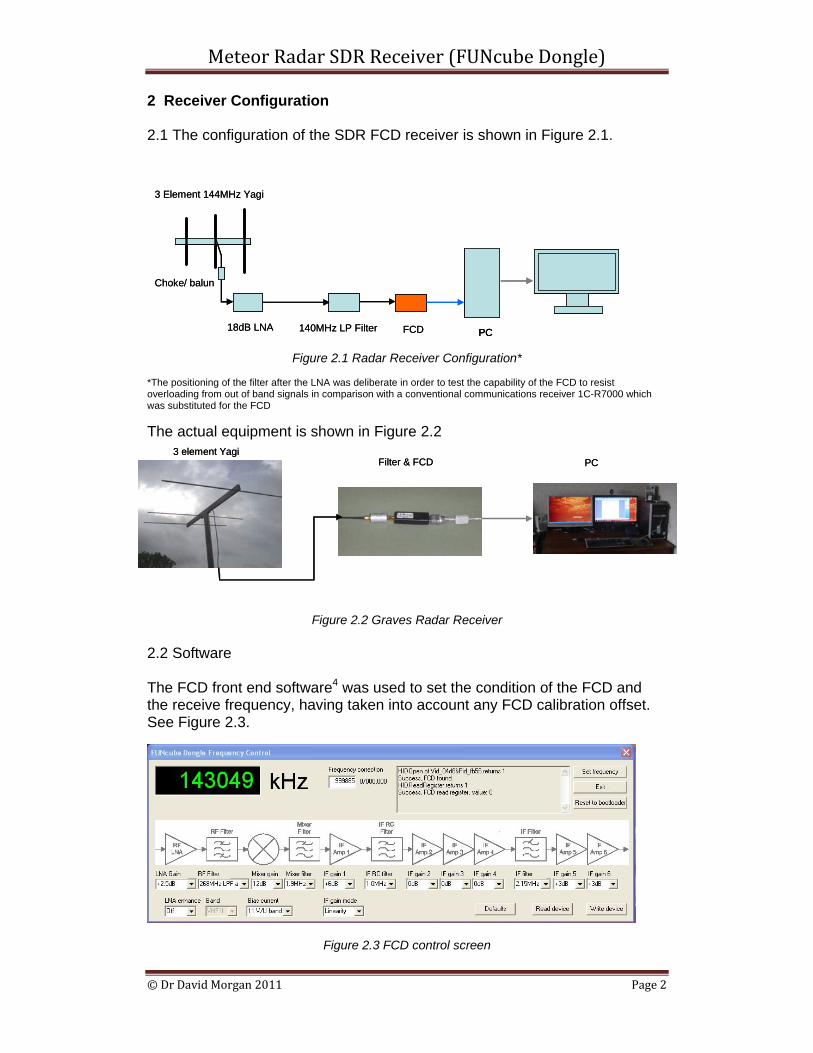
2 Receiver Configuration 2.1 The configuration of the SDR FCD receiver is shown in Figure 2.1.
Figure 2.1 Radar Receiver Configuration* *The positioning of the filter after the LNA was deliberate in order to test the capability of the FCD to resist overloading from out of band signals in comparison with a conventional communications receiver 1C-R7000 which was substituted for the FCD The actual equipment is shown in Figure 2.2
Figure 2.2 Graves Radar Receiver 2.2 Software The FCD front end software4 was used to set the condition of the FCD and the receive frequency, having taken into account any FCD calibration offset. See Figure 2.3.
Figure 2.3 FCD control screen
3 Element 144MHz Yagi
18dB LNA
Choke/ balun
140MHz LP Filter FCD PC
3 Element 144MHz Yagi
18dB LNA
Choke/ balun
140MHz LP Filter FCD PCPC
3 element YagiFilter & FCD PC
3 element YagiFilter & FCD PC
Meteor Radar SDR Receiver (FUNcube Dongle)
© Dr David Morgan 2011 Page 3
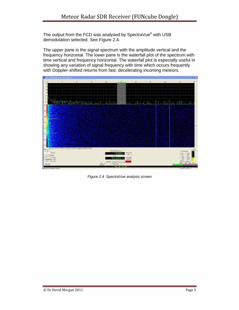
The output from the FCD was analysed by SpectraVue5 with USB demodulation selected. See Figure 2.4. The upper pane is the signal spectrum with the amplitude vertical and the frequency horizontal. The lower pane is the waterfall plot of the spectrum with time vertical and frequency horizontal. The waterfall plot is especially useful in showing any variation of signal frequency with time which occurs frequently with Doppler-shifted returns from fast, decelerating incoming meteors.
Figure 2.4 SpectraVue analysis screen
Meteor Radar SDR Receiver (FUNcube Dongle)
© Dr David Morgan 2011 Page 4
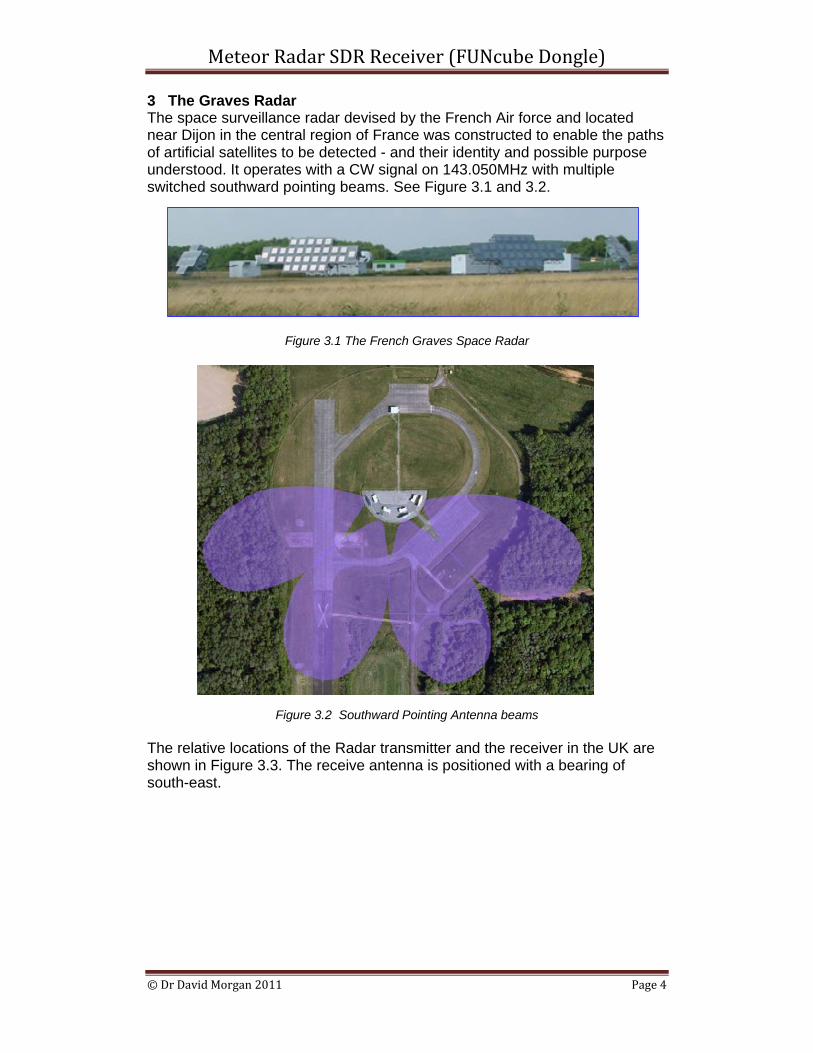
3 The Graves Radar The space surveillance radar devised by the French Air force and located near Dijon in the central region of France was constructed to enable the paths of artificial satellites to be detected - and their identity and possible purpose understood. It operates with a CW signal on 143.050MHz with multiple switched southward pointing beams. See Figure 3.1 and 3.2.
Figure 3.1 The French Graves Space Radar
Figure 3.2 Southward Pointing Antenna beams The relative locations of the Radar transmitter and the receiver in the UK are shown in Figure 3.3. The receive antenna is positioned with a bearing of south-east.
Meteor Radar SDR Receiver (FUNcube Dongle)
© Dr David Morgan 2011 Page 5
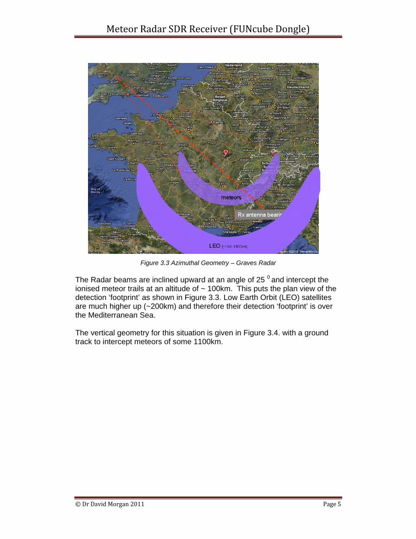
Figure 3.3 Azimuthal Geometry – Graves Radar
The Radar beams are inclined upward at an angle of 25 0 and intercept the ionised meteor trails at an altitude of ~ 100km. This puts the plan view of the detection ‘footprint’ as shown in Figure 3.3. Low Earth Orbit (LEO) satellites are much higher up (~200km) and therefore their detection ‘footprint’ is over the Mediterranean Sea. The vertical geometry for this situation is given in Figure 3.4. with a ground track to intercept meteors of some 1100km.
Meteor Radar SDR Receiver (FUNcube Dongle)
© Dr David Morgan 2011 Page 6
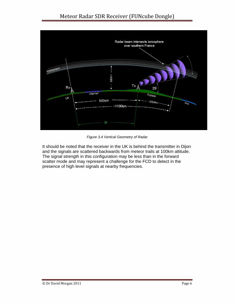
Figure 3.4 Vertical Geometry of Radar
It should be noted that the receiver in the UK is behind the transmitter in Dijon and the signals are scattered backwards from meteor trails at 100km altitude. The signal strength in this configuration may be less than in the forward scatter mode and may represent a challenge for the FCD to detect in the presence of high level signals at nearby frequencies.
Meteor Radar SDR Receiver (FUNcube Dongle)
© Dr David Morgan 2011 Page 7
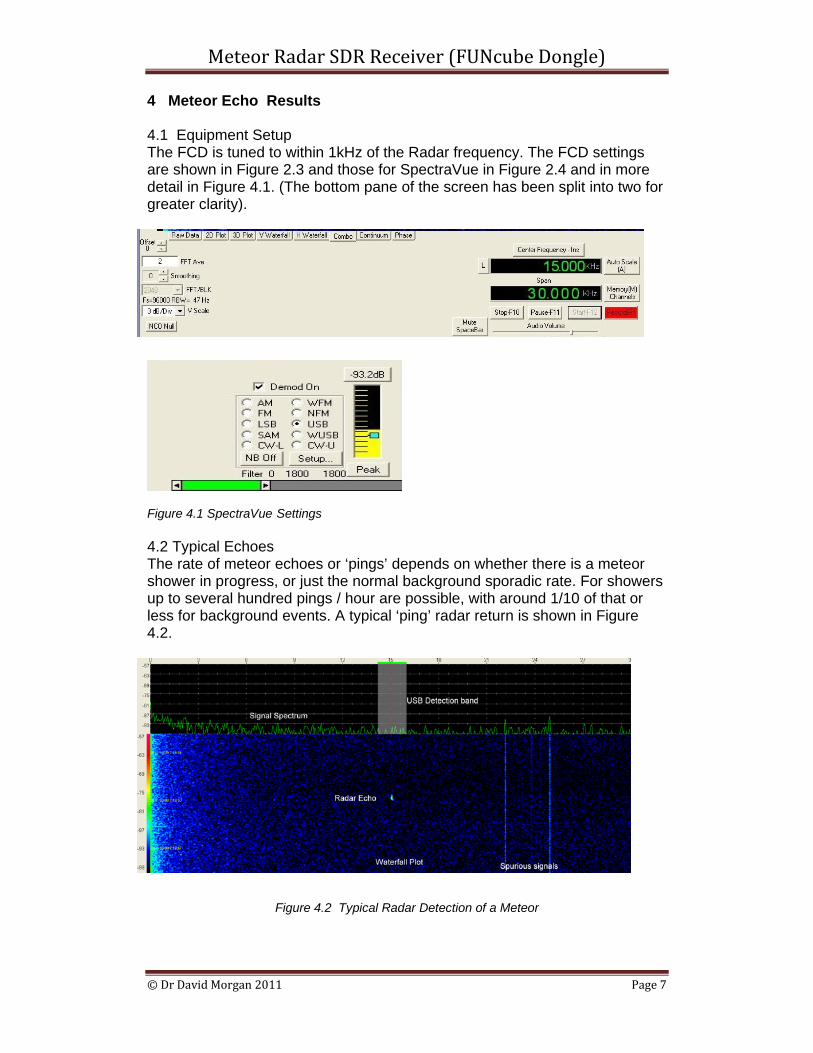
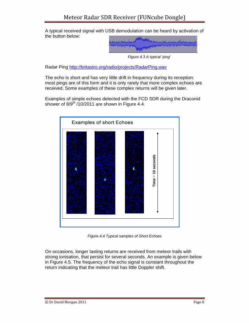
4 Meteor Echo Results 4.1 Equipment Setup The FCD is tuned to within 1kHz of the Radar frequency. The FCD settings are shown in Figure 2.3 and those for SpectraVue in Figure 2.4 and in more detail in Figure 4.1. (The bottom pane of the screen has been split into two for greater clarity). Figure 4.1 SpectraVue Settings 4.2 Typical Echoes The rate of meteor echoes or ‘pings’ depends on whether there is a meteor shower in progress, or just the normal background sporadic rate. For showers up to several hundred pings / hour are possible, with around 1/10 of that or less for background events. A typical ‘ping’ radar return is shown in Figure 4.2.
Figure 4.2 Typical Radar Detection of a Meteor
Meteor Radar SDR Receiver (FUNcube Dongle)
© Dr David Morgan 2011 Page 8
A typical received signal with USB demodulation can be heard by activation of the button below:
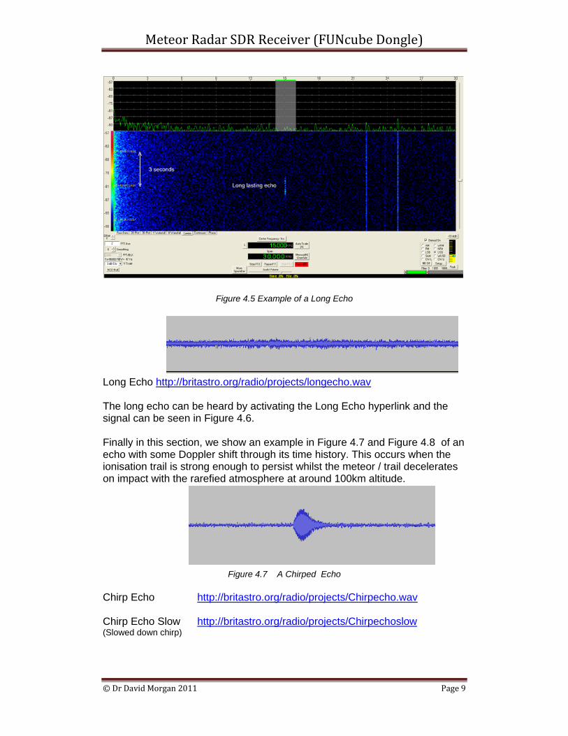
Figure 4.3 A typical ‘ping’ Radar Ping http://britastro.org/radio/projects/RadarPing.wav The echo is short and has very little drift in frequency during its reception: most pings are of this form and it is only rarely that more complex echoes are received. Some examples of these complex returns will be given later. Examples of simple echoes detected with the FCD SDR during the Draconid shower of 8/9th /10/2011 are shown in Figure 4.4.
Figure 4.4 Typical samples of Short Echoes
On occasions, longer lasting returns are received from meteor trails with strong ionisation, that persist for several seconds. An example is given below in Figure 4.5. The frequency of the echo signal is constant throughout the return indicating that the meteor trail has little Doppler shift.
Tim
e ~
10 s
econ
dsTi
me
~ 10
sec
onds
Meteor Radar SDR Receiver (FUNcube Dongle)
© Dr David Morgan 2011 Page 9
Figure 4.5 Example of a Long Echo
Figure 4.6 A long Echo Long Echo http://britastro.org/radio/projects/longecho.wav The long echo can be heard by activating the Long Echo hyperlink and the signal can be seen in Figure 4.6. Finally in this section, we show an example in Figure 4.7 and Figure 4.8 of an echo with some Doppler shift through its time history. This occurs when the ionisation trail is strong enough to persist whilst the meteor / trail decelerates on impact with the rarefied atmosphere at around 100km altitude.
Figure 4.7 A Chirped Echo Chirp Echo http://britastro.org/radio/projects/Chirpecho.wav Chirp Echo Slow http://britastro.org/radio/projects/Chirpechoslow (Slowed down chirp)
Meteor Radar SDR Receiver (FUNcube Dongle)
© Dr David Morgan 2011 Page 10
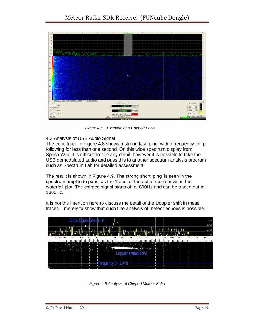
Figure 4.8 Example of a Chirped Echo 4.3 Analysis of USB Audio Signal The echo trace in Figure 4.8 shows a strong fast ‘ping’ with a frequency chirp following for less than one second. On this wide spectrum display from SpectraVue it is difficult to see any detail, however it is possible to take the USB demodulated audio and pass this to another spectrum analysis program such as Spectrum Lab for detailed assessment. The result is shown in Figure 4.9. The strong short ‘ping’ is seen in the spectrum amplitude panel as the ‘head’ of the echo trace shown in the waterfall plot. The chirped signal starts off at 800Hz and can be traced out to 1300Hz. It is not the intention here to discuss the detail of the Doppler shift in these traces – merely to show that such fine analysis of meteor echoes is possible.
Figure 4.9 Analysis of Chirped Meteor Echo
Meteor Radar SDR Receiver (FUNcube Dongle)
© Dr David Morgan 2011 Page 11
5 Conclusions From these preliminary investigations into the use of the FUNcube Dongle software radio device it is possible to draw a few conclusions:
• Using the French Graves Space Surveillance transmitter it is possible to detect meteor echoes reliably with the FCD.
• For adequate performance the FCD needs a band-limiting or, better still, a band-pass filter around the operating frequency of 143.050MHz to reduce the strong nearby signals and prevent overloading of the FCD LNA and mixer.
• A simple 3 element Yagi antenna pointed south-east is sufficient to receive the backscattered signal from meteors over southern France.
• The cost of setting up this FCD based meteor radar system is only about £200 and is affordable for interested amateurs.
• Radar observation of meteors can be an engaging activity and analysis can range for simple detection of echoes to the detailed analysis of Doppler shifted signals and the inference of the creation of the ionisation trails in the lower ionosphere.
• Setting up a system such as described in this article is quite simple and should encourage interested parties to get involved in meteor detection activities with local amateur radio clubs, astronomical societies and the British Astronomical Association 7.
Meteor Radar SDR Receiver (FUNcube Dongle)
© Dr David Morgan 2011 Page 12
Appendix A
1. Software Defined Radio A number of definitions can be found to describe Software Defined Radio or SDR. The Wireless Innovation Forum8, working in collaboration with the Institute of Electrical and Electronic Engineers (IEEE) P1900.1 group, has worked to establish a definition of SDR that provides consistency and a clear overview of the technology and its associated benefits. Simply put, Software Defined Radio is defined as: "Radio in which some or all of the physical layer functions are software defined". Software-defined radio is an implementation of a radio communication system where components that have normally been implemented in hardware (e.g. low noise amplifiers, mixers, filters, IF amplifiers, modulators/demodulators and detectors), are instead implemented by means of software on a personal computer or other computing devices. While SDR is not new, the rapidly developing capability of digital electronics makes practical many processes which used to be only conceptual 9. Large amounts of signal processing are carried out in a general-purpose processor, rather than being done in special-to-type hardware. This type of design produces a radio which can receive signals over a very wide band of frequencies (eg 50 to 2500MHz) without changing any hardware. SDR also permits different radio protocols to be accessed by using appropriate software modules. High performance software defined radios have been vigorously developed in the last decade, providing significant utility for the military and cell phone services, both of which must be flexible and capable of reconfiguration to respond to changing requirements.
2. Fun Cube Dongle The Fun Cube Dongle or ‘FCD’ is an SDR product that has recently become available in small numbers and which has been bought by amateur radio enthusiasts around the world who wish to become involved with this new technology and explore its many applications. The idea behind the development of this device was to make available a low cost unit capable of receiving signals from the FUNcube amateur satellite. This is a ‘CubeSat’ - which is a standardized format for micro-satellites having a size of 10cm x 10cm x 10cm. The FUNcube Project is a new amateur satellite project that features a 435 to 145 MHz Linear Transponder for SSB/CW operation. The project has received major initial funding from the Radio
Meteor Radar SDR Receiver (FUNcube Dongle)
© Dr David Morgan 2011 Page 13
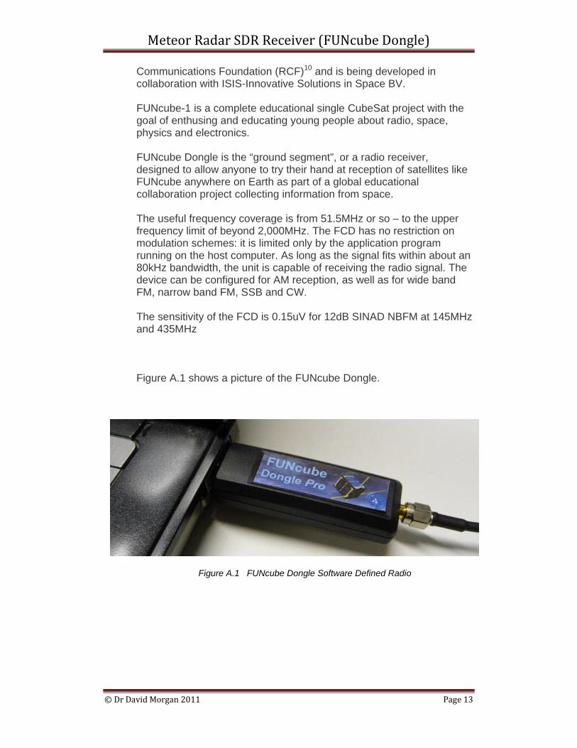
Communications Foundation (RCF)10 and is being developed in collaboration with ISIS-Innovative Solutions in Space BV. FUNcube-1 is a complete educational single CubeSat project with the goal of enthusing and educating young people about radio, space, physics and electronics. FUNcube Dongle is the “ground segment”, or a radio receiver, designed to allow anyone to try their hand at reception of satellites like FUNcube anywhere on Earth as part of a global educational collaboration project collecting information from space. The useful frequency coverage is from 51.5MHz or so – to the upper frequency limit of beyond 2,000MHz. The FCD has no restriction on modulation schemes: it is limited only by the application program running on the host computer. As long as the signal fits within about an 80kHz bandwidth, the unit is capable of receiving the radio signal. The device can be configured for AM reception, as well as for wide band FM, narrow band FM, SSB and CW. The sensitivity of the FCD is 0.15uV for 12dB SINAD NBFM at 145MHz and 435MHz Figure A.1 shows a picture of the FUNcube Dongle.
Figure A.1 FUNcube Dongle Software Defined Radio
Meteor Radar SDR Receiver (FUNcube Dongle)
© Dr David Morgan 2011 Page 14
6 References 1 www.funcubedongle.com/ 2 www.onera.fr/synindex-en/graves-radar.html 3 earthsky.org/astronomy-essentials/earthskys-meteor-shower-guide 4 groups.yahoo.com/group/FUNcube/ 5 www.moetronix.com/spectravue.htm 6 www.qsl.net/dl4yhf/spectra1.html 7 www.britastro.org/radio 8 http://www.wirelessinnovation.org/page/Introduction_to_SDR 9 Software Defined Radio: Architectures, Systems and Functions
(Markus Dillinger, Kambiz Madani, Nancy Alonistioti) Page xxxiii (Wiley & Sons, 2003, ISBN 0-470-85164-3)
10 www.commsfoundation.org/ David Morgan www.dmradas.co.uk