Embed Size (px)
Citation preview
An SDR-based Experimental Setup forOFDM-based Radar
Manuel Fuhr∗, Martin Braun∗, Christian Sturm‡, Lars Reichardt‡ and Friedrich K. Jondral∗∗Communications Engineering Lab, Karlsruhe Institute of Technology (KIT), Germany
‡Institut fur Hochfrequenztechnik und Elektronik, Karlsruhe Institute of Technology (KIT), [email protected], {martin.braun, christian.sturm, lars.reichardt, friedrich.jondral}@kit.edu
Abstract—We present a software radio-based testbed for livetesting of OFDM radar algorithms. Unlike previous testingsetups, the hardware used (Universal Software Radio Peripherals)was low-cost and low-power, thus making the measurement setupboth flexible and easy to use. The hardware can be easily batterypowered. Both stationary and mobile measurements in realisticscenarios were performed.
Index Terms—OFDM Radar, Software Defined Radio, USRP
I. INTRODUCTION
OFDM radar has recently become a focus of research for usein mobile networks which combine radar and communicationsin a single system [1], [2], [3]. Although the proposed concepthas been proven both by simulations and measurements,what is lacking is a measurement setup which is simple,small, portable and easily reconfigured. Measurement setups asdescribed in [4] are complex and expensive. To evaluate radarand data communication at the same time several communi-cation partners are required. With a simple and cost efficientsetup this would be easily achievable.
In this paper, we will present a software radio-based ap-proach using Universal Software Radio Peripherals (USRPs)which fulfills all these requirements. Although this hardwareis not optimized for radar applications, we can still show thatthe principle works fine. Many measurements were performed,both with a stationary measurement setup and from a movingvehicle. In measurements, we were able to produce radarimages with a refresh rate of 10 Hz.
The paper is organized as follows. Section II describesthe functionality of the radar system. Section III explainsthe equipment used in the measurements and gives detailson how the setup is configured. In Section IV, the differentmeasurement scenarios are shown and the measurement resultsare discussed. Section V concludes and discusses furtherimprovements.
II. RADAR SYSTEM DESCRIPTION
A. Overview
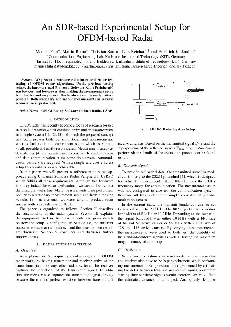
As explained in [5], acquiring a radar image with OFDMradar works by having transmitter and receiver active at thesame time, just like any other radar system. The receivercaptures the reflections of the transmitted signal. In addi-tion, the receiver also captures the transmitted signal directlybecause there is no perfect isolation between transmit and
Fig. 1: OFDM Radar System Setup
receive antennas. Based on the transmitted signal FTX and thesuperposition of the reflected signals FRX target estimation isperformed; the details of the estimation process can be foundin [5].
B. Transmit signal
To provide real-world data, the transmitted signal is mod-elled similarly to the 802.11p standard [6], which is designedfor vehicular environments. IEEE 802.11p uses the 5 GHzfrequency range for communication. The measurement setupwas not configured to also test the communication system,therefore all transmitted data simply consisted of pseudo-random sequences.
In the current state, the transmit bandwidth can be setto any value up to 25 MHz. The 802.11p standard specifiesbandwidths of 5 MHz or 10 MHz. Depending on the scenario,the signal bandwidth was either 10 MHz with a FFT sizeof 64 and 52 active carries or 25 MHz with a FFT size of128 and 116 active carriers. By varying these parameters,the measurements were used to both test the usability ofthe standard-conform signals as well as testing the maximumrange accuracy of our setup.
C. Challenges
While synchronisation is easy in simulation, the transmitterand receiver also have to be kept synchronous while perform-ing measurements. Range estimation is performed by estimat-ing the delay between transmit and receive signal; a differentstarting time for these signals would therefore severely affectthe estimated distance of an object. Analogously, Doppler
Laptop USRP (TX) USRP (RX)
TX antenna RX antenna
Ethernet MIMO cable
Fig. 2: OFDM Radar Measurement Setup
estimation consists of estimating the frequency offset of thereceived signal. If the receiving terminal’s oscillator werealready offset from the transmitter’s, the Doppler estimationwould also be affected negatively.
Another problem is the isolation between transmit andreceive terminals. Depending on the distance of the targets,the power of the reflected signal is very low. In most casesthe power of the direct coupling is higher. This limits thedynamic range.
III. MEASUREMENT SETUP
A. Hardware
The measurement setup consists of two USRP N210, eachequipped with XCVR2450 daughterboards to allow transmis-sion and reception in the 5 GHz range and a horn antenna.The USRP N210 is a popular software-defined radio whichsupports different daughterboards to transmit and receive indifferent frequency ranges. While most of the signal process-ing is done on the PC and FPGA of the USRP N210, thedaughterboard modulates the baseband signal onto the carrierfrequency. In addition to modulation several daughterboardsalso offer low-pass filtering before modulation to reducealiasing.
The XCVR2450 is the only daughterboard available forthe USRP N210 that allows transmitting and receiving in the5 GHz range. The modulation and most of the filtering ofthe XCVR2450 is performed by a MAX2829ETN, which isa 802.11a/b/g transceiver IC. Since full-duplex is not requiredfor Wireless LAN this transceiver only offers half-duplexoperation, making the XCVR2450 incapable of full-duplexoperation.
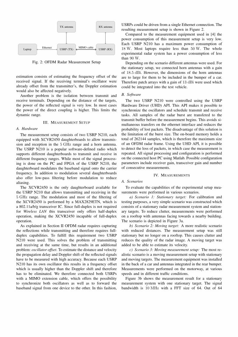
As explained in Section II OFDM radar requires capturingthe reflections while transmitting and therefore requires full-duplex capabilities. To fulfill this requirement two USRPN210 were used. This solves the problem of transmittingand receiving at the same time, but results in an additionalproblem: oscillator offset. To estimate the distance and velocitythe propagation delay and Doppler shift of the reflected signalshave to be measured with high accuracy. Because each USRPN210 has its own oscillator this results in a frequency offsetwhich is usually higher than the Doppler shift and thereforehas to be eliminated. We therefore connected both USRPswith a MIMO extension cable, which offers the possibilityto synchronize both oscillators as well as to forward thebaseband signal from one device to the other. In this fashion,
USRPs could be driven from a single Ethernet connection. Theresulting measurement setup is shown in Figure 2.
Compared to the measurement equipment used in [4] thepower consumption of this measurement setup is very low.Each USRP N210 has a maximum power consumption of18 W. Most laptops require less than 50 W. The wholeexperimental radar system has a power consumption of lessthan 90 W.
Depending on the scenario different antennas were used. Forthe stationary setup, we connected horn antennas with a gainof 18.5 dBi. However, the dimensions of the horn antennasare to large for them to be included in the bumper of a car.Therefore patch arrays with a gain of 13 dBi were used whichcould be integrated into the test vehicle.
B. Software
The two USRP N210 were controlled using the USRPHardware Driver (UHD) API. This API makes it possible tosynchronize the oscillators and schedule transmit and receivetasks. All samples of the radar burst are transfered to thetransmit buffer before the measurement begins. This avoids si-multaneous transfers on the ethernet interface and reduces theprobability of lost packets. The disadvantage of this solution isthe limitation of the burst size. The on-board memory holds atotal of 262144 samples, which is therefore the maximum sizeof an OFDM radar frame. Using the UHD API, it is possibleto detect the loss of packets, in which case the measurement isrepeated. All signal processing and configuration is performedon the connected host PC using Matlab. Possible configurationparameters include receiver gain, transceiver gain and numberof consecutive measurements.
IV. MEASUREMENTS
A. Scenarios
To evaluate the capabilities of the experimental setup mea-surements were performed in various scenarios.
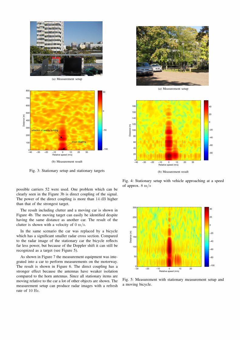
a) Scenario 1: Stationary target: For calibration andtesting purposes, a very simple scenario was constructed whichconsists of a stationary radar measurement system and station-ary targets. To reduce clutter, measurements were performedon a rooftop with antennas facing towards a nearby building.The scenario is depicted in Figure 3a.
b) Scenario 2: Moving target: A more realistic scenariowith reduced distances. The measurement setup was stillstationary but no longer on a rooftop. This causes clutter andreduces the quality of the radar image. A moving target wasadded to be able to estimate its velocity.
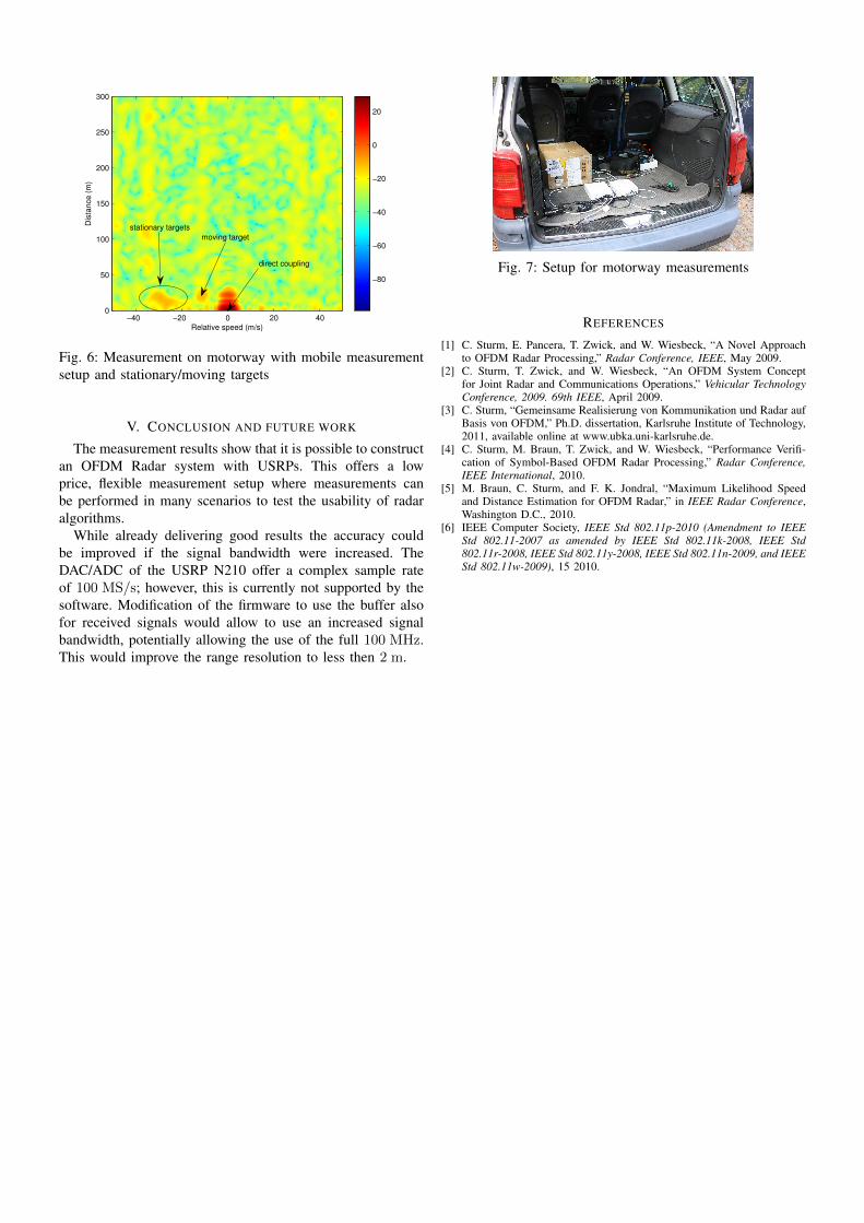
c) Scenario 3: Moving measurement setup: The most re-alistic scenario is a moving measurement setup with stationaryand moving targets. The measurement equipment was installedin the back of a car and antennas integrated in the rear bumper.Measurements were performed on the motorway, at variousspeeds and in different traffic conditions.
Figure 3b shows the measurement result for a stationarymeasurement system with one stationary target. The signalbandwidth is 10 MHz with a FFT size of 64. Out of 64
(a) Measurement setup
Relative speed (m/s)
Dis
tan
ce
(m
)
−40 −30 −20 −10 0 10 20 300
100
200
300
400
500
600
700
800
−100
−50
0
50
direct coupling
reflection of nearby building
(b) Measurement result
Fig. 3: Stationary setup and stationary targets
possible carriers 52 were used. One problem which can beclearly seen in the Figure 3b is direct coupling of the signal.The power of the direct coupling is more than 14 dB higherthan that of the strongest target.
The result including clutter and a moving car is shown inFigure 4b. The moving target can easily be identified despitehaving the same distance as another car. The result of theclutter is shown with a velocity of 0 m/s.
In the same scenario the car was replaced by a bicyclewhich has a significant smaller radar cross section. Comparedto the radar image of the stationary car the bicycle reflectsfar less power, but because of the Doppler shift it can still berecognized as a target (see Figure 5).
As shown in Figure 7 the measurement equipment was inte-grated into a car to perform measurements on the motorway.The result is shown in Figure 6. The direct coupling has astronger effect because the antennas have weaker isolationcompared to the horn antennas. Since all stationary items aremoving relative to the car a lot of other objects are shown. Themeasurement setup can produce radar images with a refreshrate of 10 Hz.
(a) Measurement setup
Relative speed (m/s)
Dis
tan
ce
(m
)
−40 −30 −20 −10 0 10 20 300
20
40
60
80
100
120
140
160
180
−80
−60
−40
−20
0
20
40
(b) Measurement result
Fig. 4: Stationary setup with vehicle approaching at a speedof approx. 8 m/s
Relative speed (m/s)
Dis
tance (
m)
−30 −20 −10 0 10 200
50
100
150
200
250
300
−100
−80
−60
−40
−20
0
20
40
Fig. 5: Measurement with stationary measurement setup anda moving bicycle.
Relative speed (m/s)
Dis
tance (
m)
−40 −20 0 20 400
50
100
150
200
250
300
−80
−60
−40
−20
0
20
moving target
stationary targets
direct coupling
Fig. 6: Measurement on motorway with mobile measurementsetup and stationary/moving targets
V. CONCLUSION AND FUTURE WORK
The measurement results show that it is possible to constructan OFDM Radar system with USRPs. This offers a lowprice, flexible measurement setup where measurements canbe performed in many scenarios to test the usability of radaralgorithms.
While already delivering good results the accuracy couldbe improved if the signal bandwidth were increased. TheDAC/ADC of the USRP N210 offer a complex sample rateof 100 MS/s; however, this is currently not supported by thesoftware. Modification of the firmware to use the buffer alsofor received signals would allow to use an increased signalbandwidth, potentially allowing the use of the full 100 MHz.This would improve the range resolution to less then 2 m.
Fig. 7: Setup for motorway measurements
REFERENCES
[1] C. Sturm, E. Pancera, T. Zwick, and W. Wiesbeck, “A Novel Approachto OFDM Radar Processing,” Radar Conference, IEEE, May 2009.
[2] C. Sturm, T. Zwick, and W. Wiesbeck, “An OFDM System Conceptfor Joint Radar and Communications Operations,” Vehicular TechnologyConference, 2009. 69th IEEE, April 2009.
[3] C. Sturm, “Gemeinsame Realisierung von Kommunikation und Radar aufBasis von OFDM,” Ph.D. dissertation, Karlsruhe Institute of Technology,2011, available online at www.ubka.uni-karlsruhe.de.
[4] C. Sturm, M. Braun, T. Zwick, and W. Wiesbeck, “Performance Verifi-cation of Symbol-Based OFDM Radar Processing,” Radar Conference,IEEE International, 2010.
[5] M. Braun, C. Sturm, and F. K. Jondral, “Maximum Likelihood Speedand Distance Estimation for OFDM Radar,” in IEEE Radar Conference,Washington D.C., 2010.
[6] IEEE Computer Society, IEEE Std 802.11p-2010 (Amendment to IEEEStd 802.11-2007 as amended by IEEE Std 802.11k-2008, IEEE Std802.11r-2008, IEEE Std 802.11y-2008, IEEE Std 802.11n-2009, and IEEEStd 802.11w-2009), 15 2010.


![OFDM - iut.ac.iromidi.iut.ac.ir/SDR/2010/Aghajan-Saberi/paper.pdf · OFDM [1] M. Wylie Interference Mitigation, [2] J. False Alarm Probabilities in Spectrum vol. 9, no. [3] T. Yücek](https://img.pdfslide.us/doc/110x75/5b279d337f8b9a80218b89dc/ofdm-iutac-ofdm-1-m-wylie-interference-mitigation-2-j-false-alarm.jpg)


![Hard Decision-Based PWM for MIMO-OFDM Radar · 2. MIMO-OFDM Radar Signal Model-Based PWM 2.1. MIMO-OFDM Radar Systems Structure In [1], OFDM technique has the advantage of combating](https://img.pdfslide.us/doc/110x75/5e6a685a5002aa073940e3bf/hard-decision-based-pwm-for-mimo-ofdm-radar-2-mimo-ofdm-radar-signal-model-based.jpg)