Embed Size (px)
Citation preview
METAL TO METAL BALL VALVES CATALOGUE
2
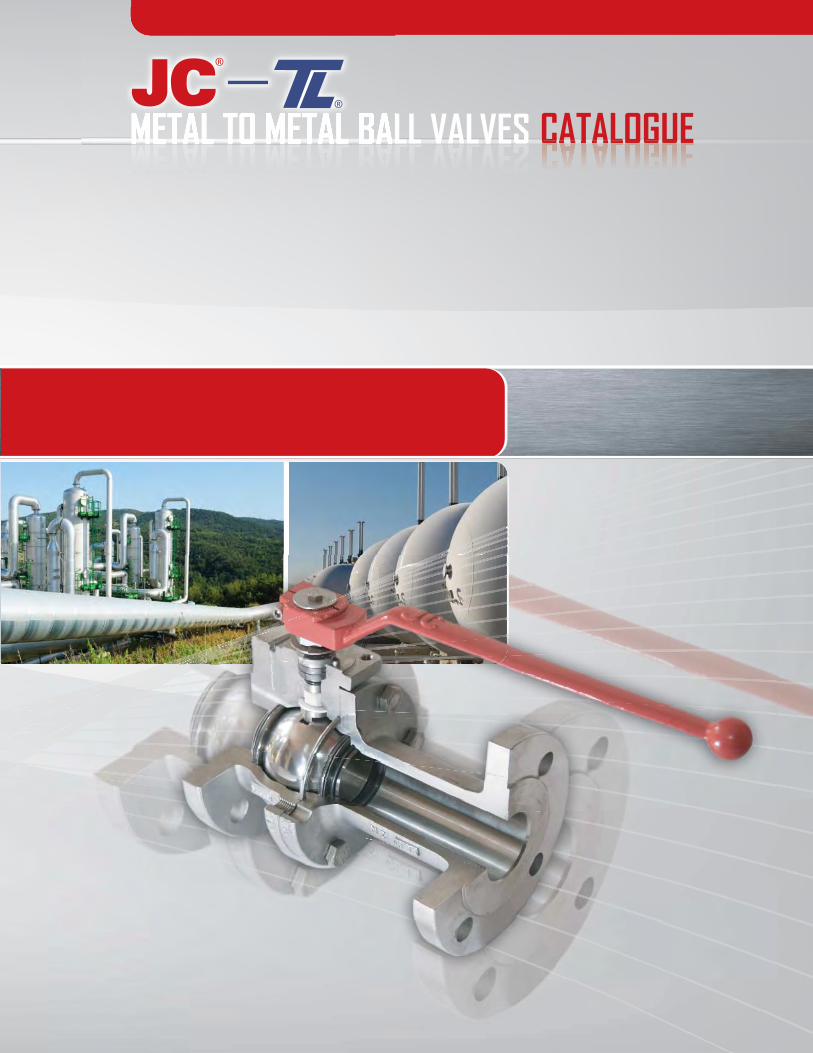
INDEX JC-TL IN THE WORLD FLOATING AND SEMI TRUNNION BALL VALVES - FIG. 515/530 - ASME-EN-STANDARD. TRUNNION FORGED BALL VALVES - FIG. 6015/6030 - ASME-API-EN STANDARD.
FLOATING WELDED BALL VALVES - FIG. B3401 (UDV) - ASME-EN STANDARD.
THREE PIECE METAL SEATED BALL VALVES - FIG. N652 ASME CE PED STANDARD.
STATE OF THE ART TECHNOLOGY - HOW TO ORDER.
DIMENSIONS
2-3
4-5
6-7
8-9
10-11
12-13
14-15
CHEMICAL INDUSTRY ENERGY INDUSTRY
WE DEVELOP VALVES FOR SPEC IAL OR STANDARD APPL ICAT IONS FOR ALL TYPES OF INDUSTRY .
OIL & GAS INDUSTRY PULP & PAPER INDUSTRY PETRO-CHEMICAL INDUSTRY

3
METAL TO METAL BALL VALVES CATALOGUECATALOGUE w w w . j c - t l . c o m w w w . jjj c t l . c o m
J C - T L i s a n i n t e r n a t i o n a l d y n a m i c c o m p a n y r e n o w n e d f o r i t ' s a b i l i t y t o d e s i g n , d e v e l o p a n d p r o d u c e b a l l v a l v e s f o r O i l a n d G a s , P e t r o c h e m i c a l , P u l p a n d P a p e r , E n e r g y a n d G e n e r a l i n d u s t r i e s f o r f o r t y y e a r s .M o d e r n p r o d u c t i o n m e t h o d s a s w e l l a s c o n t i n u o u s p r o c e s s i m p r o v e m e n t r e s u l t i n h i g h l y e f f i c i e n t p r o d u c t i o n i n a c c o r d a n c e w i t h t h e h i g h e s t i n t e r n a t i o n a l s t a n d a r d s .
J C - T L h a s i n v e s t e d i n t h e d e v e l o p m e n t o f n e w p r o d u c t s , q u a l i t y a s s u r a n c e a n d p r o t e c t i o n a g a i n s t f u g i t i v e e m i s s i o n s i n o r d e r t o a s s i s t c u s t o m e r s i n s a f e l y c o n t r o l l i n g t h e i r p r o c e s s e s . T h i s i s s u p p o r t e d b y n u m e r o u s r e f e r e n c e s f r o m s a t i s f i e d c u s t o m e r s l o c a t e d t h r o u g h o u t t h e w o r l d .
A d d i t i o n a l l y p e r s o n a l i z e d t e c h n i c a l s e r v i c e i s o f f e r e d w o r l d w i d e b y e x p e r i e n c e d s t a f f t h r o u g h o u r e x t e n s i v e n e t w o r k o f d i s t r i b u t o r s .
OUR FACILITIES
QUEBEC | CANADA ASIA, SHANGHAICHINABARCELONA | SPAIN SOUTH AMERICA
SAO PAULO BRAZIL SHARJAH | UAE
w w w . j c - t l . c o m jjjjMETAL TO METAL BALL VALVES
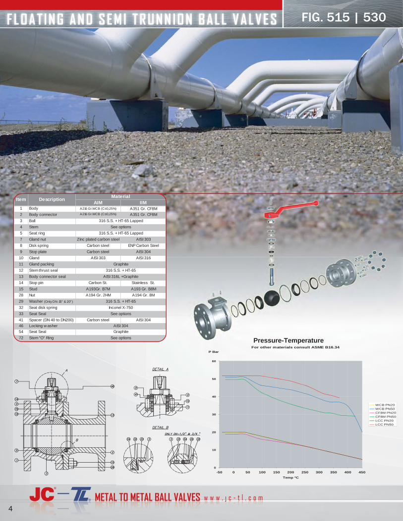
FLOAT ING AND SEMI TRUNNION BALL VALVES
4
AIM IIM1 Body A216 Gr.WCB (C ≤ 0,25%) A351 Gr. CF8M
2 Body connector A216 Gr.WCB (C ≤ 0,25%) A351 Gr. CF8M
3 Ball
4 Stem
5 Seat ring
7 Gland nut Zinc plated carbon steel AISI 303
8 Disk spring Carbon steel ENP Carbon Steel
9 Stop plate Carbon steel AISI 304
10 Gland AISI 303 AISI 316
11 Gland packing
12 Stem thrust seal
13 Body connector seal
14 Stop pin Carbon St. Stainless St.
15 Stud A193Gr. B7M A193 Gr. B8M
28 Nut A194 Gr. 2HM A194 Gr. 8M
29 Washer (Only DN-15" & 20")
32 Seat disk spring
33 Seat Seal
41 Spacer (DN 40 to DN200) Carbon steel AISI 304
46 Locking w asher
54 Seat Seal
72 Stem "O" Ring
Item DescriptionMaterial
Inconel X-750
316 S.S. + HT-65
AISI 316L +Graphite
316 S.S. + HT-65 Lapped
See options
316 S.S. + HT-65 Lapped
See options
Graphite
316 S.S. + HT-65
See options
AISI 304
Graphite
FIG. 515 | 530
For other materials consult ASME B16.34
0
10
20
30
40
50
60
-50 0 50 100 150 200 250 300 350 400 450
Temp ºC
P Bar
WCB PN20 WCB PN50 CF8M PN20 CF8M PN50 LCC PN20 LCC PN50
Pressure-Temperature

5
GENERAL CHARACTERISTICS Fig 515/3530 Series SFF Split Body Floating Ball Full Bore
DESIGN STANDARDSValves design API 6D / ISO 14313 ASME B16.34 BS 5351 NF E 29-470 ISO 17292
Body design ASME VIII Div.1
Shell thickness ASME B16.34 BS 5351 ISO 17292
Flanges ASME B16.5 Raised face
Face to face dimensions ASME B16.10 Long pattern API 6D / ISO 14313 EN 558-2 Series 3, 4 & 12
Actuator mounting flange ISO 5211
Wetted parts materials and bolting NACE MR.01.75
Shell f inishing quality MSS SP 55
Marking API 6D / ISO 14313 BS 5351 ISO 17292 CE - PED EN 19
TESTS AND CERTIFICATESQuality Assurance ISO 9001 API Q1 CE - PED
Fire Safe design BS 6755 Part 2 API 6FA ISO 10497 API 607 5 TH Edition
Pressure testing API 598 BS 6755 Part 1 ISO 5208 / ISO 17292 NF E 29-203 EN 12266
Other ISO 14001 ATEX
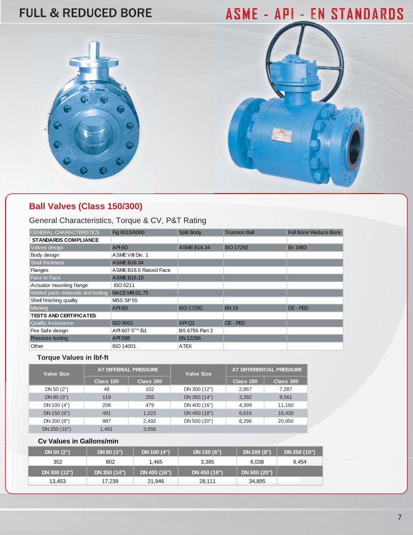
Ball Valves (Class 150/300)
General Characteristics, Torque & CV, P&T Rating
ASME - AP I - EN STANDARDSFULL & REDUCED BORE
Class 150 Class 300 Class 150 Class 30020 bar 50 bar 20 bar 50 bar
DN 15 (½") 19 23 DN 65 (2½") 103
DN 20 (¾") 23 30 DN 80 (3”) 125 211
DN 25 (1") 28 33 DN 100 (4”) 201
DN 40 (1½") 40 52 DN 150 (6") 573
DN 50 (2”) 66 100 DN 200 (8") 968
AT DIFFERENTIAL PRESSUREVALVE SIZE VALVE SIZE
AT DIFFERENTIAL PRESSURETorque Values in lbf-ft
***
***
******
*** Consult Factory
Cv Values in Gallons/min
DN 15 (½”) DN 20 (¾”) DN 25 (1”) DN 40 (1½”) DN 50 (2”)25 45 90 200 315
DN 65 (2½”) DN 80 (3”) DN 100 (4”) DN 150 (6”) DN 200 (8")
640 1,160 1,915 4,870 10,440
w w w . j c - t l . c o m jjjjjMETAL TO METAL BALL VALVES
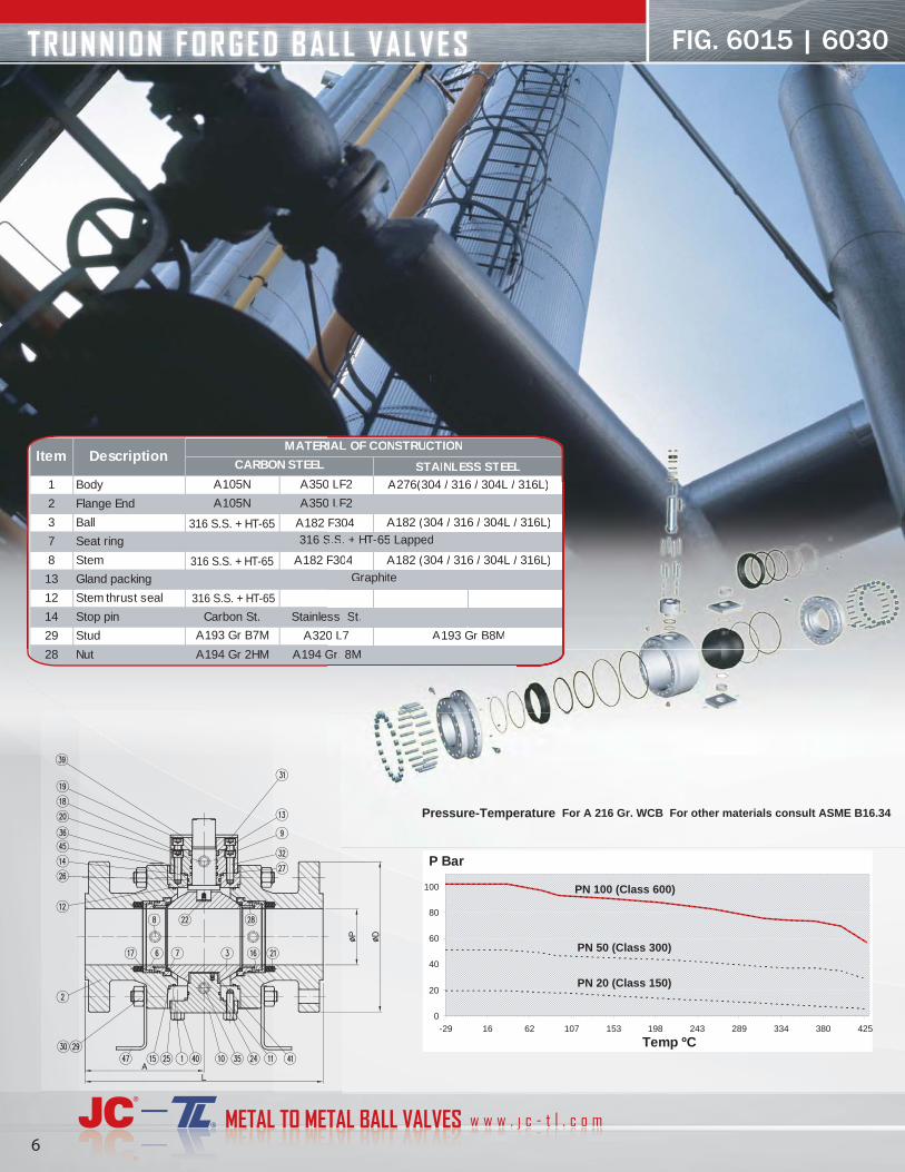
TRUNNION FORGED BALL VALVES
6
1 Body A105N A350 LF2
2 Flange End A105N A350 LF2
3 Ball A182 F304
7 Seat ring
8 Stem A182 F304
13 Gland packing
12 Stem thrust seal
14 Stop pin Carbon St. Stainless St.
29 Stud A193 Gr B7M A320 L7
28 Nut A194 Gr 2HM A194 Gr. 8M
A182 (304 / 316 / 304L / 316L)
316 S.S. + HT-65 Lapped
Item DescriptionMATERIAL OF CONSTRUCTION
CARBON STEEL STAINLESS STEELA276(304 / 316 / 304L / 316L)
A182 (304 / 316 / 304L / 316L)
Graphite
A193 Gr B8M
316 S.S. + HT-65
316 S.S. + HT-65
316 S.S. + HT-65
FIG. 6015 | 6030
0 LF2
0 LF2
F304
F304
ss St.
0 L7
Gr. 8M
A182 (304 / 316 / 304L / 316L)
S.S. + HT-TT 65 Lapped
IAL OF CONSTRURR CTION
STAINLESEE S STEELA276(304 / 316 / 304L / 316L)
A182 (304 / 316 / 304L / 316L)
Graphite
A193 Gr B8M
0
20
40
60
80
100
-29 16 62 107 153 198 243 289 334 380 425
Temp ºC
P Bar
Pressure-Temperature For A 216 Gr. WCB For other materials consult ASME B16.34
PN 20 (Class 150)
PN 50 (Class 300)
PN 100 (Class 600)
7
ASME - AP I - EN STANDARDSFULL & REDUCED BORE ASME - AAAPPPPPP IIIIII -- EEEEEEEENNNNNN SSTANDARARDARDAR
Ball Valves (Class 150/300)
General Characteristics, Torque & CV, P&T Rating
Torque Values in lbf-ft
Class 150 Class 300 Class 150 Class 300
DN 50 (2") 48 102 DN 300 (12") 2,867 7,287
DN 80 (3") 119 255 DN 350 (14") 3,392 8,561
DN 100 (4") 208 479 DN 400 (16") 4,399 11,160
DN 150 (6") 491 1,223 DN 450 (18") 6,616 16,430
DN 200 (8") 987 2,492 DN 500 (20") 8,296 20,950
DN 250 (10") 1,461 3,658
Valve Size Valve SizeAT DIFFERIAL PRESSURE AT DIFFERENTIAL PRESSURE
GENERAL CHARACTERISTICS Fig 6015/6060 Split Body Trunnion Ball Full Bore/ Reduce Bore
STANDARDS COMPLIANCEValves design API 6D ASME B16.34 ISO 17292 En 1983
1 .viD IIIV EMSAngised ydoB
Shell thickness ASME B16.34
ecaF desiaR 5.61B EMSAsegnalF
Face to Face ASME B16.10
Actuator mounting f lange ISO 5211
Wetted parts materials and bolting NACE MR.01.75
Shell f inishing quality MSS SP 55
Marking API 6D ISO 17292 EN 19 CE - PED
TESTS AND CERTIFICATESQuality Assurance ISO 9001 API Q1 CE - PED
Fire Safe design API 607 5TH Ed. BS 6755 Part 2
Pressure testing API 598 EN 12266
XETA10041 OSIrehtO
Cv Values in Gallons/min
DN 50 (2") DN 80 (3") DN 100 (4") DN 150 (6") DN 200 (8") DN 250 (10")
352 802 1,465 3,385 6,038 9,454
DN 300 (12") DN 350 (14") DN 400 (16") DN 450 (18") DN 500 (20")
13,453 17,239 21,946 28,111 34,895
w w w . j c - t l . c o m jjjjjMETAL TO METAL BALL VALVES
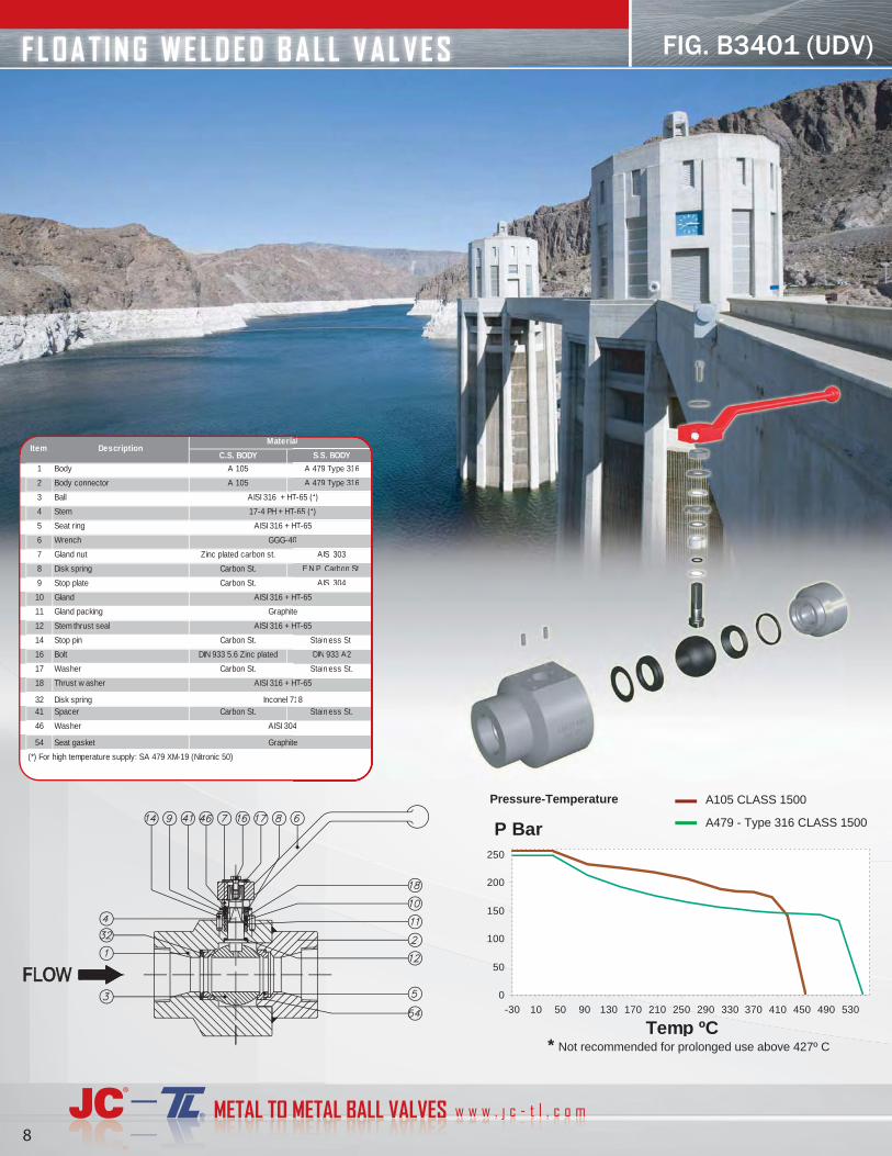
FLOAT ING WELDED BALL VALVES
8
C.S. BODY S.S. BODY
1 Body A 105 A 479 Type 316
2 Body connector A 105 A 479 Type 316
3 Ball
4 Stem
5 Seat ring
6 Wrench
7 Gland nut Zinc plated carbon st. AISI 303
8 Disk spring Carbon St. E.N.P. Carbon St.
9 Stop plate Carbon St. AISI 304
10 Gland
11 Gland packing
12 Stem thrust seal
14 Stop pin Carbon St. Stainless St.
16 Bolt DIN 933 5.6 Zinc plated DIN 933 A2
17 Washer Carbon St. Stainless St.
18 Thrust w asher
32 Disk spring 41 Spacer Carbon St. Stainless St.
46 Washer
54 Seat gasket
17-4 PH + HT-65 (*)
AISI 316 + HT-65
Inconel 718
AISI 304
GGG-40
(*) For high temperature supply: SA 479 XM-19 (Nitronic 50)
Item DescriptionMaterial
Graphite
Graphite
AISI 316 + HT-65
AISI 316 + HT-65
AISI 316 + HT-65 (*)
AISI 316 + HT-65
S.S. BODYDD
A 479 TyTT pe 316
A 479 TyTT pe 316
AISI 303
E.N.P. CaC rbon St.
AISI 304
Stainless St.
DIN 933 A2
Stainless St.
Stainless St.
T-TT 65 (*)
HT-TT 65
718
4
0
al
te
te
HT-TT 65
HT-TT 65
T-TT 65 (*)
HT-TT 65
FIG. B3401 (UDV)
Pressure-Temperature
* Not recommended for prolonged use above 427º C
0
50
100
150
200
250
-30 10 50 90 130 170 210 250 290 330 370 410 450 490 530
Temp ºC
P Bar
A105 CLASS 1500
A479 - Type 316 CLASS 1500
9
ASME - EN STANDARDSASMREDUCED BORE
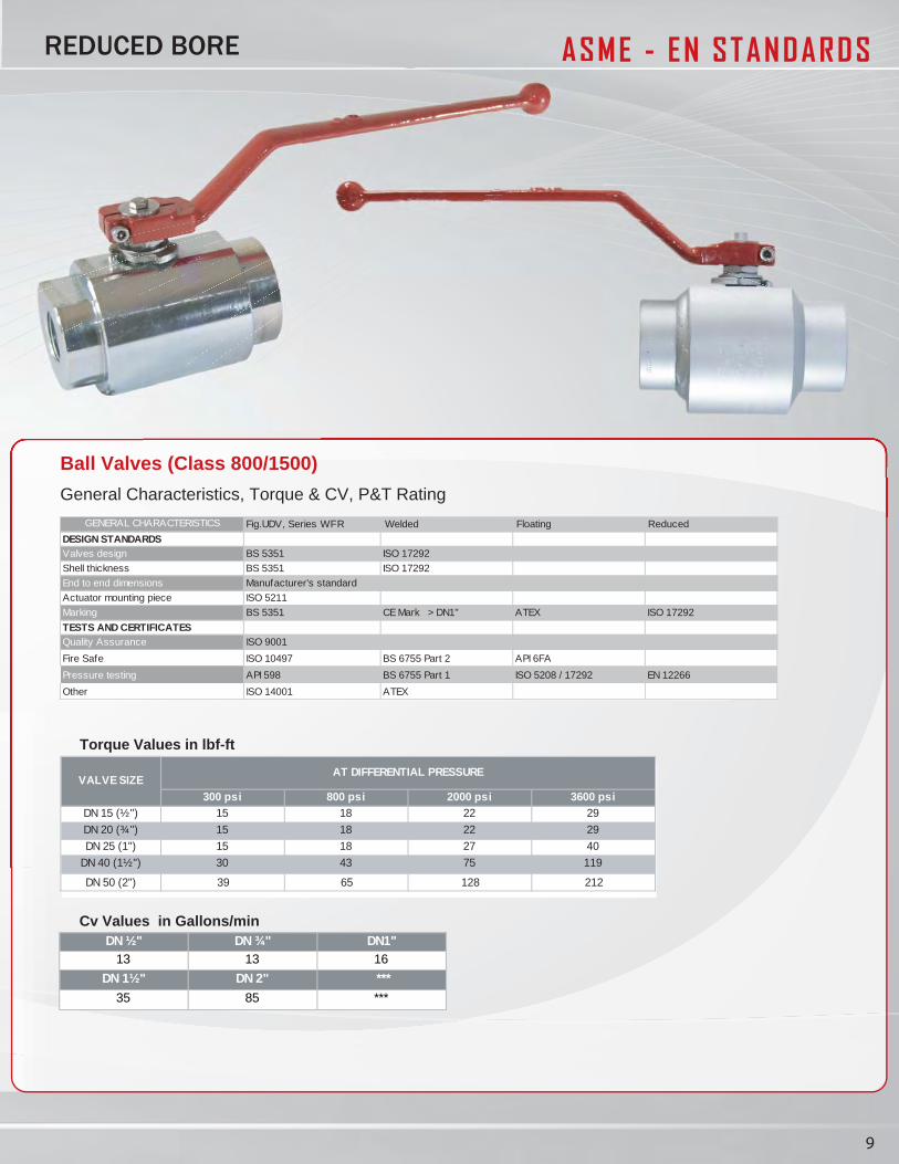
GENERAL CHARACTERISTICS Fig.UDV, Series WFR Welded Floating Reduced
DESIGN STANDARDSValves design BS 5351 ISO 17292
Shell thickness BS 5351 ISO 17292
End to end dimensions Manufacturer's standard
Actuator mounting piece ISO 5211
Marking BS 5351 CE Mark > DN1" ATEX ISO 17292
TESTS AND CERTIFICATESQuality Assurance ISO 9001
Fire Safe ISO 10497 BS 6755 Part 2 API 6FA
Pressure testing API 598 BS 6755 Part 1 ISO 5208 / 17292 EN 12266
Other ISO 14001 ATEX
Ball Valves (Class 800/1500)
General Characteristics, Torque & CV, P&T Rating
300 psi 800 psi 2000 psi 3600 psiDN 15 (½") 15 18 22 29
DN 20 (¾") 15 18 22 29
DN 25 (1") 15 18 27 40
DN 40 (1½") 30 43 75 119
DN 50 (2") 39 65 128 212
VALVE SIZEAT DIFFERENTIAL PRESSURE
Torque Values in lbf-ft
DN ½" DN ¾" DN1"13 13 16
DN 1½" DN 2" ***
35 85 ***
Cv Values in Gallons/min
w w w . j c - t l . c o m jjjjjMETAL TO METAL BALL VALVES 10
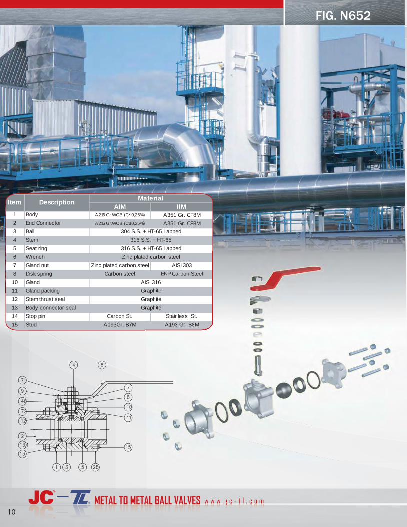
AIM IIM1 Body A216 Gr.WCB (C ≤ 0,25%) A351 Gr. CF8M
2 End Connector A216 Gr.WCB (C ≤ 0,25%) A351 Gr. CF8M
3 Ball
4 Stem
5 Seat ring
6 Wrench
7 Gland nut Zinc plated carbon steel AISI 303
8 Disk spring Carbon steel ENP Carbon Steel
10 Gland
11 Gland packing
12 Stem thrust seal
13 Body connector seal
14 Stop pin Carbon St. Stainless St.
15 Stud A193Gr. B7M A193 Gr. B8M
Item DescriptionMaterial
Graphite
Graphite
316 S.S. + HT-65
304 S.S. + HT-65 Lapped
316 S.S. + HT-65 Lapped
Zinc plated carbon steel
AISI 316
Graphite
FIG. N652
el AISI 303
ENP CaCC rbon Steel
Stainless St.
A193 Gr. B8M
raphite
raphite
pp
ed carbon steel
ISI 316
raphite
11
ASME - CE PED STANDARDS
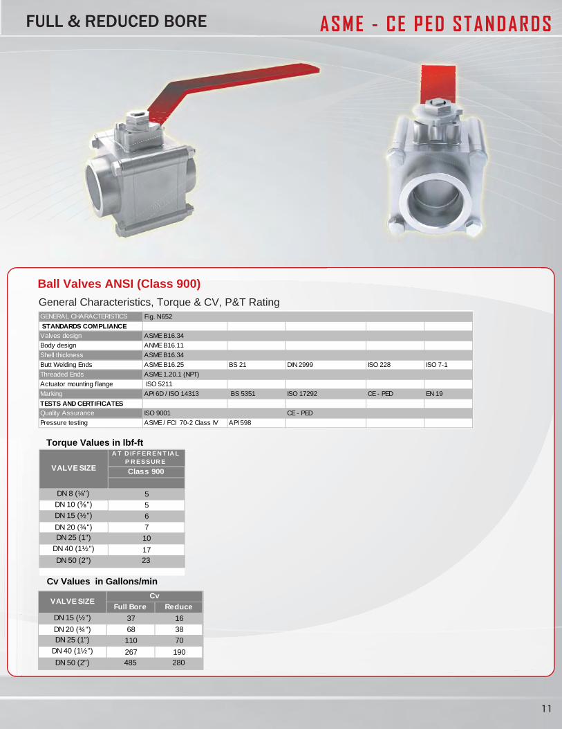
Ball Valves ANSI (Class 900)General Characteristics, Torque & CV, P&T RatingGENERAL CHARACTERISTICS
STANDARDS COMPLIANCEValves design ASME B16.34
11.61B EMNAngised ydoB
Shell thickness ASME B16.34
Butt Welding Ends ASME B16.25 BS 21 DIN 2999 ISO 228 ISO 7-1
Threaded Ends ASME 1.20.1 (NPT)
Actuator mounting flange ISO 5211
Marking API 6D / ISO 14313 BS 5351 ISO 17292 CE - PED EN 19
TESTS AND CERTIFICATESQuality Assurance ISO 9001 CE - PED
Pressure testing ASME / FCI 70-2 Class IV API 598
FULL & REDUCED BORE
Fig. N652
Full Bore Reduce DN 15 (½") 37 16
DN 20 (¾") 68 38DN 25 (1") 110 70
DN 40 (1½") 267 190DN 50 (2”) 485 280
VALVE SIZECv
Cv Values in Gallons/min
A T D IF F ER EN T IA LP R ESSUR E
Class 900
DN 8 (¼") 5DN 10 (⅜") 5DN 15 (½") 6
DN 20 (¾") 7DN 25 (1") 10
DN 40 (1½") 17DN 50 (2”) 23
VALVE SIZE
Torque Values in lbf-ft
12
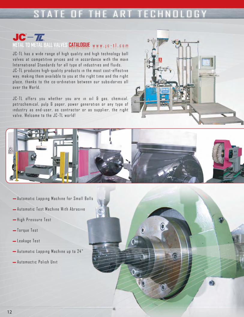
METAL TO METAL BALL VALVES CATALOGUE CATALOGUUEE w w w . j c - t l . c o m ww w w . jjjj c t l . c o mmmm
J C - T L h a s a w i d e r a n g e o f h i g h q u a l i t y a n d h i g h t e c h n o l o g y b a l l v a l v e s a t c o m p e t i t i v e p r i c e s a n d i n a c c o r d a n c e w i t h t h e m a i n I n t e r n a t i o n a l S t a n d a r d s f o r a l l t y p e o f i n d u s t r i e s a n d f l u i d s . J C - T L p r o d u c e s h i g h - q u a l i t y p r o d u c t s i n t h e m o s t c o s t - e f f e c t i v e w a y , m a k i n g t h e m a v a i l a b l e t o y o u a t t h e r i g h t t i m e a n d t h e r i g h t p l a c e , t h a n k s t o t h e c o - o r d i n a t i o n b e t w e e n o u r s u b s i d a r i e s a l l o v e r t h e W o r l d .
J C - T L o f f e r s y o u w h e t h e r y o u a r e i n o i l & g a s , c h e m i c a l , p e t r o c h e m i c a l , p u l p & p a p e r , p o w e r g e n e r a t i o n o r a n y t y p e o f i n d u s t r y a s e n d - u s e r , a s c o n t r a c t o r o r a s s u p p l i e r , t h e r i g h t v a l v e . W e l c o m e t o t h e J C - T L w o r l d !
A u t o m a t i c L a p p i n g M a c h i n e f o r S m a l l B a l l s
A u t o m a t i c T e s t M a c h i n e W i t h A b r a s i v e
H i g h P r e s s u r e T e s t
T o r q u e T e s t
L e a k a g e T e s t
A u t o m a t i c L a p p i n g M a c h i n e u p t o 2 4 ”
A u t o m a c t i c P o l i s h U n i t
S T A T E O F T H E A R T T E C H N O L O G Y
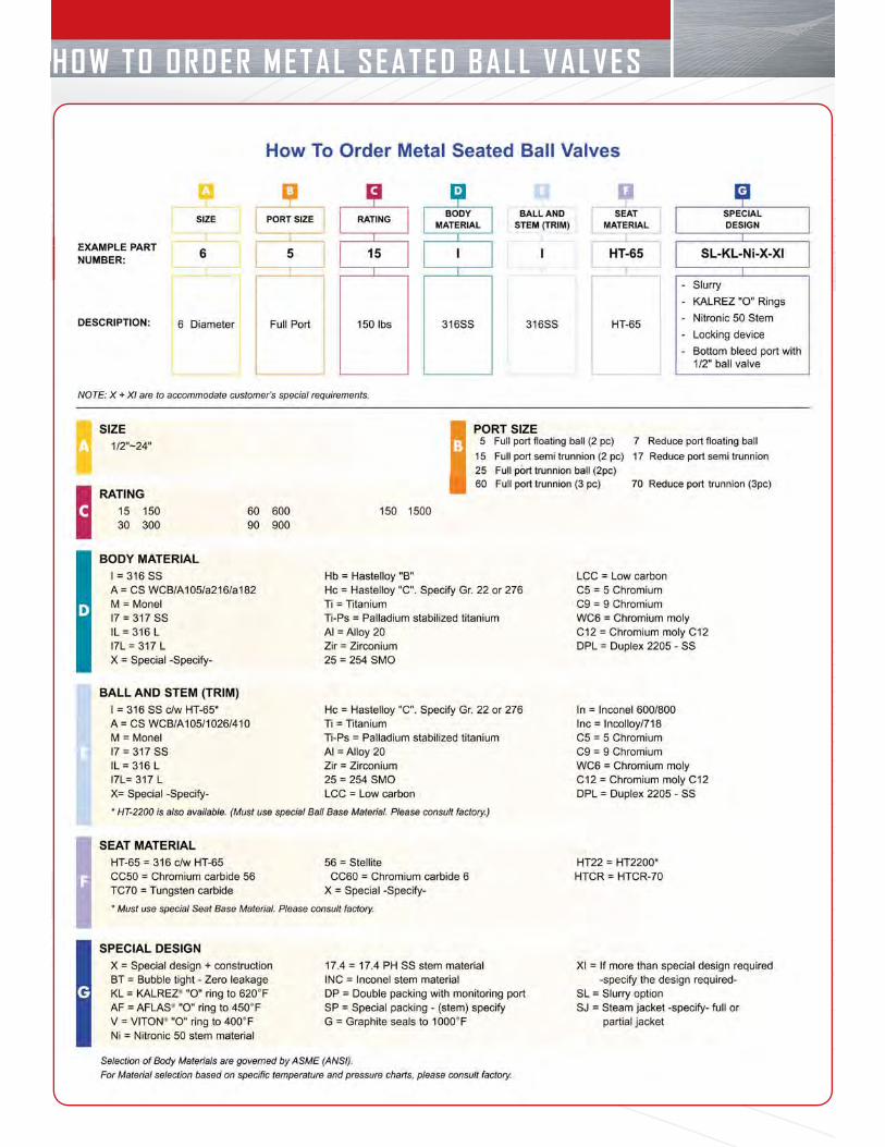
HOW TO ORDER METAL SEATED BALL VALVES
(*) Dimensions in mm and weight in kg.
DN Ød L (RF) L (BW) H1 H2 WEIGHT50 (2” x 1 1/2") 38 178 216 110 160 26
50 (2”) 51 178 216 120 175 30
80 (3” x 2") 51 203 283 120 175 33
80 (3”) 76 203 283 150 210 60
100 (4” x 3") 76 229 305 150 210 64
100 (4”) 102 229 305 165 255 103
150 (6” x 4") 102 394 457 165 255 110
150 (6”) 152 394 457 190 280 188
200 (8” x 6") 152 457 521 190 280 185
200 (8”) 203 457 521 225 320 250
250 (10” x 8") 203 533 559 225 320 290
250 (10”) 254 533 559 265 370 435
300 (12” x 10") 254 610 635 265 370 505
300 (12”) 305 610 635 280 380 610
350 (14" x 12") 305 686 762 280 380 685
350 (14") 337 686 762 310 435 825
400 (16" x 14") 337 762 838 310 435 880
400 (16") 387 762 838 350 470 1010
450 (18" x 16") 387 864 914 350 470 1100
450 (18") 438 864 914 405 510 1360
500 (20" x 18") 438 914 991 405 510 1500
500 (20") 489 914 991 460 530 1905
600 (24" x 20") 489 1067 1143 460 530 2050
600 (24") 591 1067 1143 530 635 3070
750 (30" x 24") 591 1295 1397 530 635 3300
750 (30") 737 1295 1397 660 760 5210
800 (32" x 30") 737 1371 1524 710 760 5600
800 (32") 781 1371 1524 710 790 6820
850 (34" x 32") 781 1473 1626 760 790 7200
850 (34") 813 1473 1626 760 810 7600900 (36" x34") 813 1524 1728 790 810 8100
900 (36") 876 1524 1728 790 890 8810
Series: 6015, 6115, 7015, 7115 PN 20 (Class 150)
w w w . j c - t l . c o mMETAL TO METAL BALL VALVES14 15
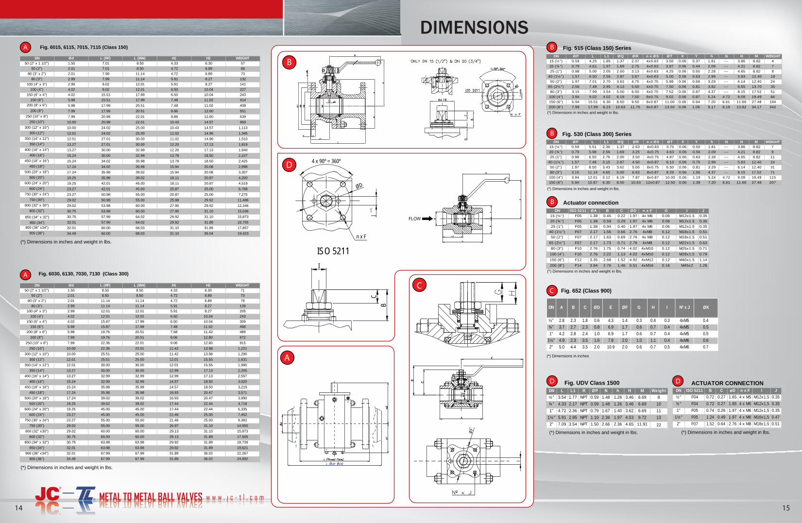
DIMENSIONS
I
CB
ØD
n x F
J-0.0
5
4 x 90º = 360º
ISO 5211
Fig. 515 (Class 150) Series
(*) Dimensions in inches and weight in lbs.
DN ØP L L1 ØQ ØR n x ØS ØT X Y h N H M WEIGHT15 (½”) 0.59 4.25 1.85 1.37 2.37 4x0.63 3.50 0.06 0.37 1.81 --- 3.86 8.82 4
20 (¾") 0.79 4.61 1.97 1.69 2.75 4x0.63 3.87 0.06 0.44 2.09 --- 4.21 8.82 7
25 (1") 0.98 5.00 2.05 2.00 3.13 4x0.63 4.25 0.06 0.50 2.28 --- 4.65 8.82 8
40 (1½”) 1.57 6.50 2.56 2.87 3.87 4x0.63 5.00 0.06 0.63 2.99 --- 5.83 12.40 18
50 (2”) 1.97 7.01 2.70 3.62 4.75 4x0.75 5.98 0.06 0.69 3.29 --- 6.14 12.40 24
65 (2½”) 2.56 7.48 2.95 4.13 5.50 4x0.75 7.00 0.06 0.81 3.82 --- 6.65 13.70 35
80 (3”) 3.15 7.99 3.54 5.00 6.00 4x0.75 7.52 0.06 0.87 4.37 --- 8.15 17.52 51
100 (4”) 3.94 9.02 4.02 6.19 7.50 8x0.75 9.02 0.06 0.87 5.24 4.72 9.09 19.49 84
150 (6”) 5.94 15.51 6.30 8.50 9.50 8x0.87 11.00 0.06 0.94 7.20 6.61 11.69 27.48 194
200 (8”) 7.99 17.99 8.23 10.63 11.75 8x0.87 13.50 0.06 1.06 9.17 8.19 13.82 34.17 342
Fig. 530 (Class 300) SeriesDN ØP L L1 ØQ ØR n x ØS ØT X Y h N H M WEIGHT
15 (½”) 0.59 5.51 2.36 1.37 2.63 4x0.63 3.75 0.06 0.50 1.81 --- 3.86 8.82 7
20 (¾") 0.79 5.98 2.56 1.69 3.25 4x0.75 4.63 0.06 0.56 2.09 --- 4.21 8.82 9
25 (1") 0.98 6.50 2.76 2.00 3.50 4x0.75 4.87 0.06 0.63 2.28 --- 4.65 8.82 11
40 (1½”) 1.57 7.48 3.15 2.87 4.50 4x0.87 6.13 0.06 0.75 2.99 --- 5.83 12.40 24
50 (2”) 1.97 8.50 3.43 3.62 5.00 8x0.75 6.50 0.06 0.81 3.29 --- 6.14 12.40 31
80 (3”) 3.15 11.14 4.65 5.00 6.63 8x0.87 8.29 0.06 1.06 4.37 --- 8.15 17.52 71
100 (4”) 3.94 12.01 5.12 6.19 7.87 8x0.87 10.00 0.06 1.19 5.24 4.72 9.09 19.49 115
150 (6”) 5.94 15.87 6.30 8.50 10.63 12x0.87 12.50 0.06 1.38 7.20 6.61 11.69 27.48 207
(*) Dimensions in inches and weight in lbs.
Actuator connectionDN ISO 5211 ØA B C ØD n x F G I J
15 (½”) F05 1.38 0.45 0.22 1.97 4x M6 0.06 M12x1.5 0.35
20 (¾") F05 1.38 0.59 0.29 1.97 4x M6 0.06 M12x1.5 0.35
25 (1") F05 1.38 0.94 0.40 1.97 4x M6 0.06 M12x1.5 0.35
40 (1½ ”) F07 2.17 1.56 0.66 2.76 4xM8 0.12 M18x1.5 0.51
50 (2”) F07 2.17 1.63 0.69 2.76 4x M8 0.12 M18x1.5 0.51
65 (2½ ”) F07 2.17 1.73 0.71 2.76 4xM8 0.12 M22x1.5 0.63
80 (3”) F10 2.76 1.75 0.74 4.02 4xM10 0.12 M25x1.5 0.71
100 (4”) F10 2.76 2.22 1.13 4.02 4xM10 0.12 M28x1.5 0.79
150 (6”) F12 3.35 2.68 1.52 4.92 4xM12 0.12 M40x1.5 1.14
200 (8”) F14 3.94 2.76 1.46 5.51 4xM16 0.16 M45x2 1.26
(*) Dimensions in inches and weight in lbs.
Fig. UDV Class 1500
(*) Dimensions in inches and weight in lbs.
DN L L1 R ØP N h H M Weight
½" 3.54 1.77 NPT 0.59 1.48 1.26 3.46 6.69 8
¾" 4.33 2.17 NPT 0.59 1.48 1.26 3.46 6.69 10
1" 4.72 2.36 NPT 0.79 1.67 1.40 3.62 6.69 11
1½" 5.91 2.95 NPT 1.10 2.36 1.97 4.53 9.72 13
2" 7.09 3.54 NPT 1.50 2.66 2.36 4.65 11.91 22
ACTUATOR CONNECTION
(*) Dimensions in inches and weight in lbs.
DN ISO 5211 B C øD n x F I J
½ " F04 0.72 0.27 1.65 4 x M5 M12x1,5 0.35
¾ " F04 0.72 0.27 1.65 4 x M5 M12x1,5 0.35
1" F05 0.74 0.26 1.97 4 x M6 M12x1,5 0.35
1½" F05 1.24 0.49 1.97 4 x M6 M16x1,5 0.47
2" F07 1.52 0.64 2.76 4 x M8 M18x1,5 0.51
D
B
A B
B
C
B
D D
A
C
A
(*) Dimensions in inches and weight in lbs.
DN Ød L (RF) L (BW) H1 H2 WEIGHT50 (2” x 1 1/2") 1.50 7.01 8.50 4.33 6.30 57
50 (2”) 2.01 7.01 8.50 4.72 6.89 66
80 (3” x 2") 2.01 7.99 11.14 4.72 6.89 73
80 (3”) 2.99 7.99 11.14 5.91 8.27 132
100 (4” x 3") 2.99 9.02 12.01 5.91 8.27 141
100 (4”) 4.02 9.02 12.01 6.50 10.04 227
150 (6” x 4") 4.02 15.51 17.99 6.50 10.04 243
150 (6”) 5.98 15.51 17.99 7.48 11.02 414
200 (8” x 6") 5.98 17.99 20.51 7.48 11.02 408
200 (8”) 7.99 17.99 20.51 8.86 12.60 551
250 (10” x 8") 7.99 20.98 22.01 8.86 12.60 639
250 (10”) 10.00 20.98 22.01 10.43 14.57 959
300 (12” x 10") 10.00 24.02 25.00 10.43 14.57 1,113
300 (12”) 12.01 24.02 25.00 11.02 14.96 1,345
350 (14" x 12") 12.01 27.01 30.00 11.02 14.96 1,510
350 (14") 13.27 27.01 30.00 12.20 17.13 1,819
400 (16" x 14") 13.27 30.00 32.99 12.20 17.13 1,940
400 (16") 15.24 30.00 32.99 13.78 18.50 2,227
450 (18" x 16") 15.24 34.02 35.98 13.78 18.50 2,425
450 (18") 17.24 34.02 35.98 15.94 20.08 2,998
500 (20" x 18") 17.24 35.98 39.02 15.94 20.08 3,307
500 (20") 19.25 35.98 39.02 18.11 20.87 4,200
600 (24" x 20") 19.25 42.01 45.00 18.11 20.87 4,519
600 (24") 23.27 42.01 45.00 20.87 25.00 6,768
750 (30" x 24") 23.27 50.98 55.00 20.87 25.00 7,275
750 (30") 29.02 50.98 55.00 25.98 29.92 11,486
800 (32" x 30") 29.02 53.98 60.00 27.95 29.92 12,346
800 (32") 30.75 53.98 60.00 27.95 31.10 15,036
850 (34" x 32") 30.75 57.99 64.02 29.92 31.10 15,873
850 (34") 32.01 57.99 64.02 29.92 31.89 16,755
900 (36" x34") 32.01 60.00 68.03 31.10 31.89 17,857
900 (36") 34.49 60.00 68.03 31.10 35.04 19,423
Fig. 6015, 6115, 7015, 7115 (Class 150)
DN Ød L (RF) L (BW) H1 H2 WEIGHT50 (2” x 1 1/2") 1.50 8.50 8.50 4.33 6.30 71
50 (2”) 2.01 8.50 8.50 4.72 6.89 73
80 (3” x 2") 2.01 11.14 11.14 4.72 6.89 79
80 (3”) 2.99 11.14 11.14 5.91 8.27 139
100 (4” x 3") 2.99 12.01 12.01 5.91 8.27 205
100 (4”) 4.02 12.01 12.01 6.50 10.04 243
150 (6” x 4") 4.02 15.87 17.99 6.50 10.04 309
150 (6”) 5.98 15.87 17.99 7.48 11.02 498
200 (8” x 6") 5.98 19.76 20.51 7.68 11.42 489
200 (8”) 7.99 19.76 20.51 9.06 12.80 672
250 (10” x 8") 7.99 22.36 22.01 9.06 12.80 915
250 (10”) 10.00 22.36 22.01 11.42 13.98 1,221
300 (12” x 10") 10.00 25.51 25.00 11.42 13.98 1,290
300 (12”) 12.01 25.51 25.00 12.01 15.55 1,631
350 (14" x 12") 12.01 30.00 30.00 12.01 15.55 1,995
350 (14") 13.27 30.00 30.00 12.99 17.13 2,205
400 (16" x 14") 13.27 32.99 32.99 12.99 17.13 2,557
400 (16") 15.24 32.99 32.99 14.57 18.50 3,020
450 (18" x 16") 15.24 35.98 35.98 14.57 18.50 3,219
450 (18") 17.24 35.98 35.98 16.93 20.47 3,571
500 (20" x 18") 17.24 39.02 39.02 16.93 20.47 3,990
500 (20") 19.25 39.02 39.02 17.44 22.44 4,718
600 (24" x 20") 19.25 45.00 45.00 17.44 22.44 5,335
600 (24") 23.27 45.00 45.00 21.46 25.00 7,452
750 (30" x 24") 23.27 55.00 55.00 21.46 25.00 9,392
750 (30") 29.02 55.00 55.00 26.97 31.10 14,550
800 (32" x30") 29.02 60.00 60.00 29.13 31.10 15,873
800 (32") 30.75 60.00 60.00 29.13 31.89 17,505
850 (34" x 32") 30.75 63.98 63.98 29.92 31.89 18,739
850 (34") 32.01 63.98 63.98 29.92 31.89 19,621
900 (36" x34") 32.01 67.99 67.99 31.89 36.02 22,267
900 (36") 34.49 67.99 67.99 31.89 36.02 24,692
Fig. 6030, 6130, 7030, 7130 (Class 300)
(*) Dimensions in inches and weight in lbs.
½" 2.8 2.3 1.8 0.6 4.3 1.4 0.3 0.4 0.3 4xM5 0.4
¾" 3.7 2.7 2.3 0.8 6.9 1.7 0.6 0.7 0.4 4xM5 0.5
1" 4.2 2.8 2.4 1.0 6.9 1.7 0.6 0.7 0.4 4xM5 0.5
1½" 4.9 2.3 3.5 1.6 7.8 2.0 1.0 1.1 0.4 4xM6 0.6
2" 5.0 4.4 3.5 2.0 10.9 2.0 0.6 0.7 0.5 4xM6 0.7
I Nº x J ØKE ØF G HØDDN A B C
(*) Dimensions in inches
Fig. 652 (Class 900)
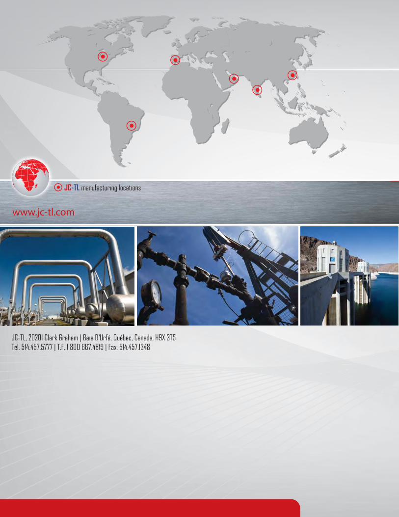
JC-TL, 20201 Clark Graham | Baie D’Urfé, Québec, Canada, H9X 3T5 Tel. 514.457.5777 | T.F. 1 800 667.4819 | Fax. 514.457.1348
www.jc-tl.com
JC-TL manufacturing locations