Embed Size (px)
Citation preview
Installation, Operation and Maintenance Manual Metal Seated Floating Ball Valve Document #: DHV-IOM-MSFBV-19 Published: September 2019
Revision: 0
Page 1 of 22
INSTALLATION, OPERATION AND MAINTENANCE MANUAL
METAL SEATED
FLOATING BALL VALVE
Installation, Operation and Maintenance Manual Metal Seated Floating Ball Valve Document #: DHV-IOM-MSFBV-19 Published: September 2019
Revision: 0
Page 2 of 22
TABLE OF CONTENTS
TYPICAL CONFIGURATION .................................................................................................................. 3
FOREWORD ......................................................................................................................................... 4
1. END USER INSTRUCTION ................................................................................................................ 4
2. VALVE TRANSPORTATION AND STORAGE ....................................................................................... 5
2.1 TRANSPORTATION ......................................................................................................................... 5
2.2 STORAGE ....................................................................................................................................... 7
3. VALVE INSTALLATION ...................................................................................................................... 7
3.1 INSPECTION BEFORE INSTALLATION ............................................................................................. 8
3.2 INSTALLATION ............................................................................................................................... 8
4. VALVE OPERATION ........................................................................................................................ 11
5. VALVE MAINTENANCE .................................................................................................................. 13
6. DETAILED DISASSEMBLY AND ASSEMBLY ...................................................................................... 15
6.1 TRUNNION BALL VALVE DISASSEMBLY ....................................................................................... 15
6.2 TRUNNION BALL VALVE ASSEMBLY ............................................................................................. 16
7. TROUBLESHOOTING...................................................................................................................... 19
8. WARRANTY AND SERVICE ............................................................................................................. 20
8.1 VALVE WARRANTY PERIOD ......................................................................................................... 20
8.2 SERVICE ....................................................................................................................................... 20
APPENDIX I – INSTALLATION REQUIREMENTS .................................................................................. 21
Installation, Operation and Maintenance Manual Metal Seated Floating Ball Valve Document #: DHV-IOM-MSFBV-19 Published: September 2019
Revision: 0
Page 3 of 22
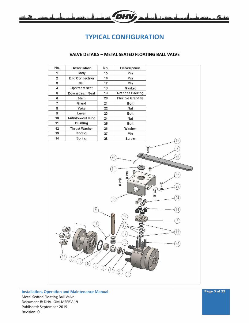
TYPICAL CONFIGURATION
VALVE DETAILS – METAL SEATED FLOATING BALL VALVE
Installation, Operation and Maintenance Manual Metal Seated Floating Ball Valve Document #: DHV-IOM-MSFBV-19 Published: September 2019
Revision: 0
Page 4 of 22
FOREWORD
Personal safety and Long Term Ownership of your DHV API-6D Trunnion Ball Valve is the most
important matter in reviewing our Installation, Operation & Maintenance Manual. This manual will
provide all the necessary safety guidelines for our valve including information for the valve
transportation, storage, installation, operation and maintenance. Please read carefully before
installing or servicing the valve.
DHV provides general guidelines in this manual, and cannot provide specific data and warnings for all
possible applications. The purchaser/end user must therefore assume responsibility for proper valve
selection, sizing, installation, operation, and maintenance of DHV valve products. The purchaser/end
user should read and understand this document and any instructions provided with the product, and
conduct training with its employees and contractors to ensure they are aware of the proper and safe
use of DHV valve products in connection with the specific application.
1. ENDUSER INSTRUCTION
Personnel safety is always the most important factor in the transportation, storage, installation,
operation and maintenance of any valve. DHV valves are designed to meet the customer’s order
requirements and specifications. DHV disclaims all responsibility for problems that may be caused by
applications other than the specified use. Valve service pressure/temperature information is detailed
on the valve name plate. When selecting a valve, always consider the application, service and
temperature for the intended service. Select the applicable valve material for anti-corrosion and anti-
abrasive service. For safety of personnel and plant/environment: Prior to conducting any service to
the valve, ensure the valve is not under pressure, properly vented, and drained before servicing. For
all electric, hydraulic or pneumatic actuated valves, all power connections to the valve/actuator must
be turned off before performing any maintenance and service. When performing any operation,
maintenance or service, personal protective equipment should be used, such as protective clothing,
oxygen masks, safety glasses, work gloves, etc. DHV will not be responsible for any loss or expense
resulting from the failure of equipment, damage to any property, or death or injury to any person
resulting in whole or in part from repairs or modification performed by other than authorized DHV
personnel. Such unauthorized repairs shall also serve to terminate any contractual or other warranty,
if any, on the equipment and may result in equipment no longer meeting applicable requirements.
Installation, Operation and Maintenance Manual Metal Seated Floating Ball Valve Document #: DHV-IOM-MSFBV-19 Published: September 2019
Revision: 0
Page 5 of 22
2. VALVE TRANSPORTATION AND STORAGE
2.1 TRANSPORTATION
1. Valves should remain in the open position to prevent damage to the seating surface during shipping
and handling. Each valve should be securely packaged either on a pallet or in a crate to avoid any
damage during shipping.
2. Use the proper hoisting equipment to transport the valve, especially during lifting or lowering the
valve. Special attention to personnel safety and the care of the valve should be made when
transporting the valve. Avoid impacting or striking the valve during transportation. Lay the valve on a
clean flat surface; make sure to avoid laying the valve on the flange face. Ensure there is adequate
clearance around the valve for proper operation and maintenance.
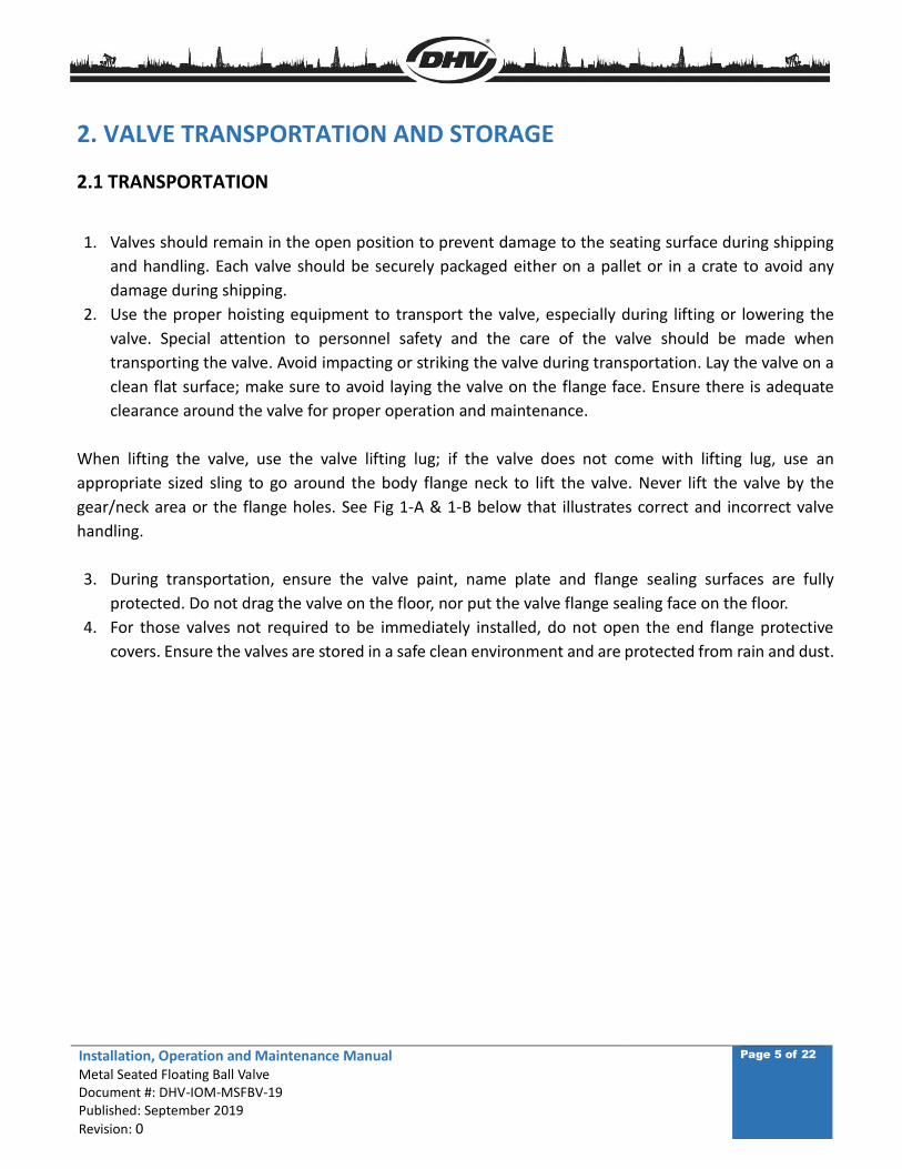
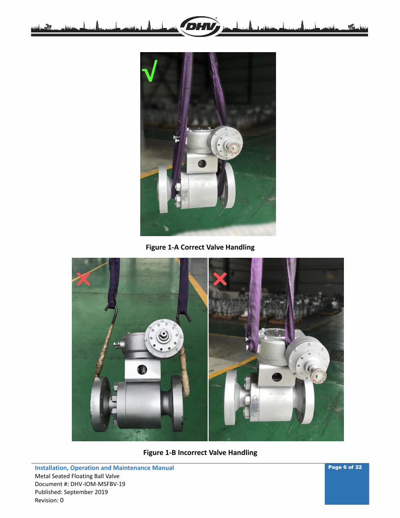
When lifting the valve, use the valve lifting lug; if the valve does not come with lifting lug, use an
appropriate sized sling to go around the body flange neck to lift the valve. Never lift the valve by the
gear/neck area or the flange holes. See Fig 1-A & 1-B below that illustrates correct and incorrect valve
handling.
3. During transportation, ensure the valve paint, name plate and flange sealing surfaces are fully
protected. Do not drag the valve on the floor, nor put the valve flange sealing face on the floor.
4. For those valves not required to be immediately installed, do not open the end flange protective
covers. Ensure the valves are stored in a safe clean environment and are protected from rain and dust.
Installation, Operation and Maintenance Manual Metal Seated Floating Ball Valve Document #: DHV-IOM-MSFBV-19 Published: September 2019
Revision: 0
Page 6 of 22
Figure 1-A Correct Valve Handling
Figure 1-B Incorrect Valve Handling
Installation, Operation and Maintenance Manual Metal Seated Floating Ball Valve Document #: DHV-IOM-MSFBV-19 Published: September 2019
Revision: 0
Page 7 of 22
2.2 STORAGE
1. Valves should be stored in the open position. Valve ports and flange serration surfaces should be kept
sealed with protective flange covers.
2. Valves should be stored in a dust free, low humidity and well ventilated room, not in direct contact to
the floor. If possible, the valves shall be kept in the original packing box. If valves have to be stored
outdoors, keep the valve in the original crate or shipping container. Ensure the valve packaging is stored
on raised blocking to avoid moisture damage. Protective covering should be used for protection against
dust and rain.
3. Valves should never be stacked on top of each other, to avoid any valve distortion which may affect
valve performance and cause personnel injury.
4. Valves that have been stored for an extended period of time should be cleaned and inspected prior to
installation. Inspect the sealing surface to ensure it is clean and free of any debris or damage.
5. Do not expose the valve to any corrosive environment as this may cause damage to the valve
components.
3. VALVE INSTALLATION
Review all documentation to fully understand the valve and related information that will provide safe
installation and a long service life for your valve.
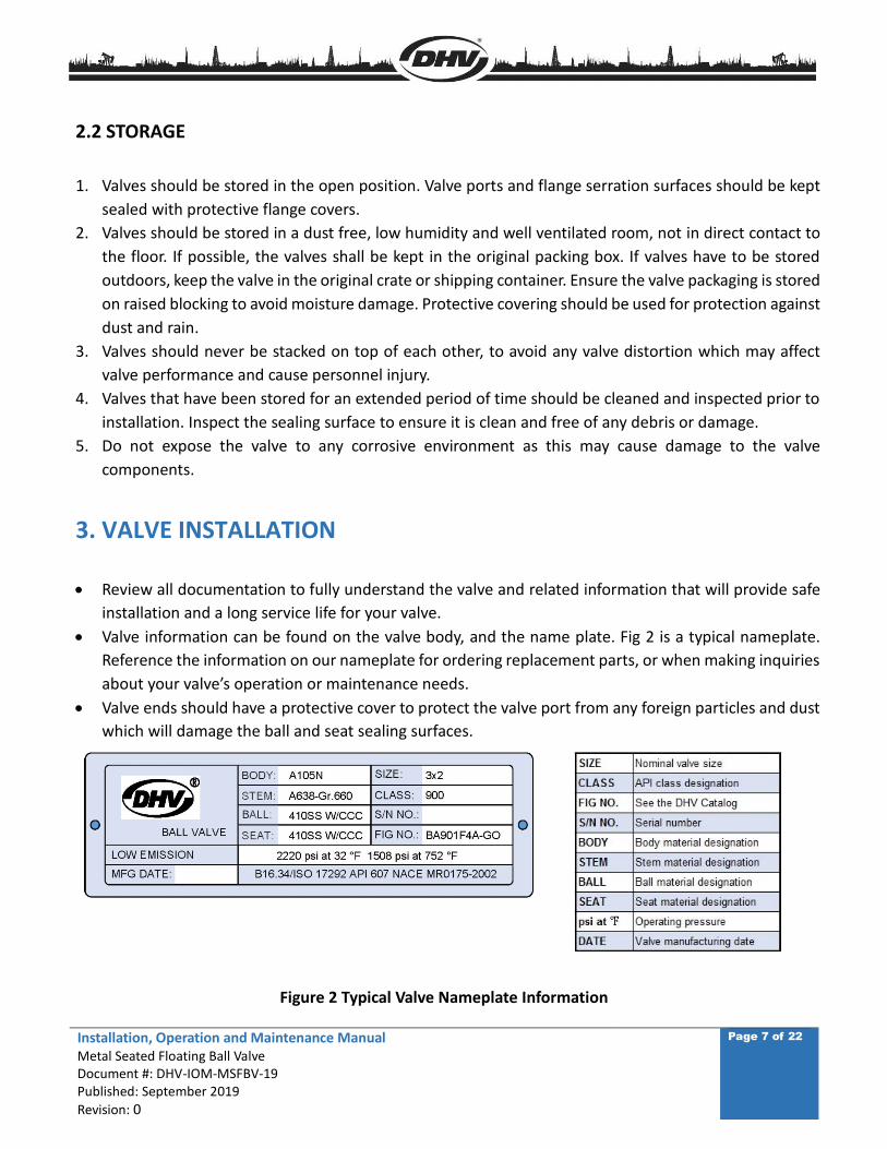
Valve information can be found on the valve body, and the name plate. Fig 2 is a typical nameplate.
Reference the information on our nameplate for ordering replacement parts, or when making inquiries
about your valve’s operation or maintenance needs.
Valve ends should have a protective cover to protect the valve port from any foreign particles and dust
which will damage the ball and seat sealing surfaces.
Figure 2 Typical Valve Nameplate Information
Installation, Operation and Maintenance Manual Metal Seated Floating Ball Valve Document #: DHV-IOM-MSFBV-19 Published: September 2019
Revision: 0
Page 8 of 22
3.1 INSPECTION BEFORE INSTALLATION
3.1.1 Before installation, check the valve nameplate and valve body information to ensure the valve is
suitable for the intended service.
3.1.2 Before installation, remove the flange cover and the protective film on the flange sealing face, inspect
the ports and the flange sealing surface, remove any dirt with a clean soft cloth, use an anti-corrosive
cleaning liquid to clean if necessary, and never use any other chemical products.
3.1.3 Inspect the flange gasket (including ring gasket) sealing surface and ensure it is in acceptable
condition for installation.
3.1.4 After cleaning the valve and before installation, open and close the valve one time. Ensure the valve
cycles smoothly. If abnormal operation is experienced, stop the operation and inspect the valve internals
for any obstructions that may be preventing normal operation.
3.1.5 After successfully cycling and assuring the proper operation of the valve, return the valve to the open
position and ensure the valve sealing surfaces are protected until installation is complete.
3.2 INSTALLATION
3.2.1 Position the valve into the pipe or the flange connection; ensure that any stresses caused by improper
pipe alignment are relieved. Valves are not intended to be a means of aligning improperly fitted pipe.
3.2.2 Install the valve using qualified piping standards and practices. Valves marked with flow direction
must be installed in line with the piping flow.
3.2.3 The recommended orientation for ball valves is upright with the valve in a horizontal line. The valve
may be installed in other orientations; however, any deviation from recommended horizontal position may
compromise proper valve operation and void the warranty.
FLANGE ENDS:
Select the proper gasket (including ring gasket) to install, line up the bolt holes between the valve flange
and pipeline flange, then install the bolts and nuts and tighten to the accepted piping and bolting
standards. The bolt threads should be lubricated first for ease of bolting.
Use an appropriate sized torque wrench when tightening the bolt/nut, to avoid flange deformation.
Please follow Fig 3 and Table 1 for bolting sequence and bolting torque. If the bolting quantity is
different from the chart shown, please follow the same principle to get a new sequence to follow.
For large diameter valves, the valve must be properly and safely supported during installation. After
installation is completed, valve supports should be moved to the bottom of the valve flanges.
After valve installation is complete, recheck and tighten the bolts including the gland bolts as necessary
to the values provided in Table1 & Figure 3
Installation, Operation and Maintenance Manual Metal Seated Floating Ball Valve Document #: DHV-IOM-MSFBV-19 Published: September 2019
Revision: 0
Page 9 of 22
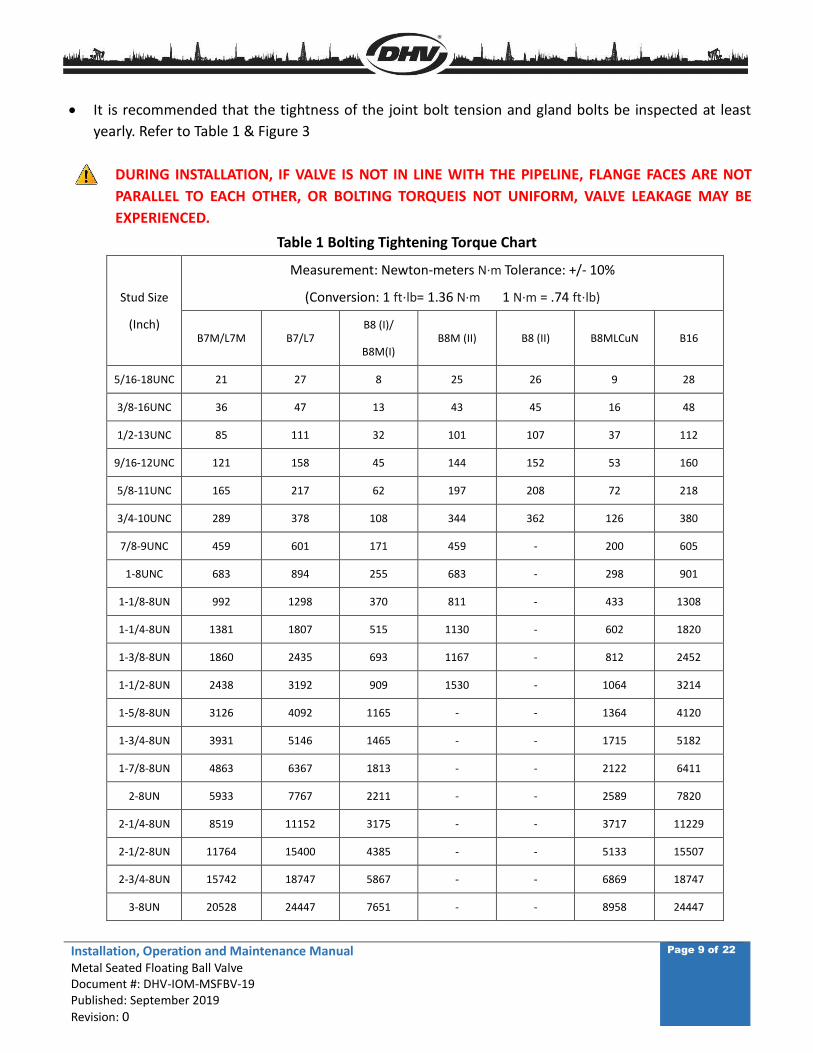
It is recommended that the tightness of the joint bolt tension and gland bolts be inspected at least
yearly. Refer to Table 1 & Figure 3
DURING INSTALLATION, IF VALVE IS NOT IN LINE WITH THE PIPELINE, FLANGE FACES ARE NOT
PARALLEL TO EACH OTHER, OR BOLTING TORQUEIS NOT UNIFORM, VALVE LEAKAGE MAY BE
EXPERIENCED.
Table 1 Bolting Tightening Torque Chart
Stud Size
(Inch)
Measurement: Newton-meters N·m Tolerance: +/- 10%
(Conversion: 1 ft⋅lb= 1.36 N·m 1 N·m = .74 ft⋅lb)
B7M/L7M B7/L7 B8 (I)/
B8M(I) B8M (II) B8 (II) B8MLCuN B16
5/16-18UNC 21 27 8 25 26 9 28
3/8-16UNC 36 47 13 43 45 16 48
1/2-13UNC 85 111 32 101 107 37 112
9/16-12UNC 121 158 45 144 152 53 160
5/8-11UNC 165 217 62 197 208 72 218
3/4-10UNC 289 378 108 344 362 126 380
7/8-9UNC 459 601 171 459 - 200 605
1-8UNC 683 894 255 683 - 298 901
1-1/8-8UN 992 1298 370 811 - 433 1308
1-1/4-8UN 1381 1807 515 1130 - 602 1820
1-3/8-8UN 1860 2435 693 1167 - 812 2452
1-1/2-8UN 2438 3192 909 1530 - 1064 3214
1-5/8-8UN 3126 4092 1165 - - 1364 4120
1-3/4-8UN 3931 5146 1465 - - 1715 5182
1-7/8-8UN 4863 6367 1813 - - 2122 6411
2-8UN 5933 7767 2211 - - 2589 7820
2-1/4-8UN 8519 11152 3175 - - 3717 11229
2-1/2-8UN 11764 15400 4385 - - 5133 15507
2-3/4-8UN 15742 18747 5867 - - 6869 18747
3-8UN 20528 24447 7651 - - 8958 24447
Installation, Operation and Maintenance Manual Metal Seated Floating Ball Valve Document #: DHV-IOM-MSFBV-19 Published: September 2019
Revision: 0
Page 10 of 22
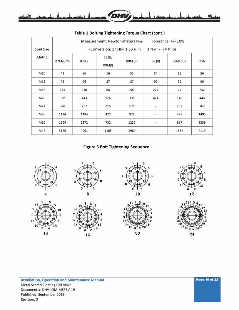
Table 1 Bolting Tightening Torque Chart (cont.)
Stud Size
(Metric)
Measurement: Newton-meters N·m Tolerance: +/- 10%
(Conversion: 1 ft⋅lb= 1.36 N·m 1 N·m = .74 ft⋅lb)
B7M/L7M B7/L7 B8 (I)/
B8M(I) B8M (II) B8 (II) B8MLCuN B16
M10 43 56 16 51 54 19 56
M12 73 96 27 87 92 32 96
M16 175 230 66 209 221 77 232
M20 338 443 126 338 424 148 446
M24 578 757 215 578 - 252 762
M30 1134 1484 422 928 - 495 1495
M36 1964 2572 732 1232 - 857 2589
M42 3125 4091 1165 1960 - 1364 4119
Figure 3 Bolt Tightening Sequence
Installation, Operation and Maintenance Manual Metal Seated Floating Ball Valve Document #: DHV-IOM-MSFBV-19 Published: September 2019
Revision: 0
Page 11 of 22
WELD ENDS:
Weld ends must be kept clean with no burrs, oil, dirt or foreign objects.
The valve end and pipe end must be in proper alignment for effective welding.
Follow the approved WPS to perform the welding. Ensure that the temperature of the body/seats area
does not exceed 200°F, verify this temperature with a Tempil stick; welding too close to the
seat/sealing area will cause area distortion. Protect the valve port area to prevent welding slag and
foreign matter from entering the valve.
After welding, use approved and proper Non-Destructive Testing (NDT) method to check the welds;
clean the welds thoroughly, and then perform local heat treatment if required.
When installation is complete, prior to system testing and start-up, clean the valve by flushing the line
of debris and other materials that may have accumulated inside the valve and in the valve seating area
and surfaces during construction. When flushing the valve, open the valve fully, flush for a determined
time based on line size. Close the valve to allow the fluid to fill the line; operate the valve to the half
open and half closed position repeatedly, this action allows the fluid to build up within the valve
assisting in flushing heavier debris from the valve. Fully close the valve, if seat leakage is noted after
flushing, repeat flushing procedure. If leakage from the seat is still evident, the seating surface maybe
damaged and need repair. If the valve is equipped with seat injection, the seats should be charged with
a valve lubricant to displace any residual fluids or moisture in the seal areas of the valve.
DURING WELDING, THE TEMPERATURE NEAR THE VALVE SEAT INSERT AND ANY O-RING AREAS
SHOULD NEVER EXCEED 94°C/200°F. A TEMPERATURE INDICATING DEVICE SHOULD BE USED TO
MONITOR THE TEMPERATURE DURING THE WELDING. THIS ALSO APPLIES TO POST WELD HEAT
TREATMENT.
4. VALVE OPERATION
To assure maximum valve performance, only use a valve that is suitable for the rated
pressure/temperature and corrosive environment.
For your safety and normal operation, please read the following valve operation procedures:
4.1 The valve must be kept either in the fully open or fully closed position. Never throttle or leave the
valve at the half-open position as erosion of the ball and seating surface may occur and damage will result.
4.2 Valve open and closed positions are indicated on the valve gear box or lever. Rotating the valve hand
wheel clockwise will close the valve; counter-clockwise operation will open the valve, this is also applicable
to gear or motor actuated operation.
4.3 There are position stops for the valve at the fully open and fully closed position. When the valve
lever or hand wheel will not rotate any further it means the valve is already at the fully open or fully closed
Installation, Operation and Maintenance Manual Metal Seated Floating Ball Valve Document #: DHV-IOM-MSFBV-19 Published: September 2019
Revision: 0
Page 12 of 22
position. The open/close stroke is 90°.
4.4 Lever operated valves are in the open position when the lever is in-line with the flow centerline.
Conversely when the lever is perpendicular to the flow centerline the valve is in the closed position. Gear
operated valves will have a position indicator on the gear.
4.5 Never operate the valve without authorization and a full understanding of the safe operation
procedures, inspections and proper handling instructions.
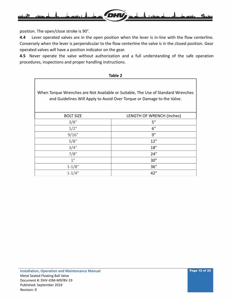
Table 2
When Torque Wrenches are Not Available or Suitable, The Use of Standard Wrenches
and Guidelines Will Apply to Avoid Over Torque or Damage to the Valve.
BOLT SIZE LENGTH OF WRENCH (inches)
3/8" 5"
1/2" 6"
9/16" 9"
5/8" 12"
3/4" 18"
7/8" 24"
1" 30"
1-1/8" 36"
1-1/4" 42"
Installation, Operation and Maintenance Manual Metal Seated Floating Ball Valve Document #: DHV-IOM-MSFBV-19 Published: September 2019
Revision: 0
Page 13 of 22
5. VALVE MAINTENANCE
Valves should be inspected regularly during operation and any findings should receive immediate attention
in order to avoid any further damage to the valve or the system. Regular inspection and maintenance
should be scheduled at a minimum of twice per year, or more often if required.
5.1 In less corrosive environments, it is suggested to check the valve body thickness every six months. In
more corrosive environments, it should be checked every three months. If the measured wall thickness is
less than specified in ASME B16.34, the valve should be replaced immediately.
5.2 The valve seat pocket area is a primary area where the operation of the valve can be affected by
debris and contaminants within the line. To ensure the seat’s operational movement within the valve, it is
recommended that the valve seat pockets be cleaned routinely with a product designed for the valve trim
and the service needs. Routine service can vary depending on the severity of the operating service of the
valve. Once the valve is in service, it is recommended to use a seat cleaning detergent or light lubricant to
clean the seat sealing surface of any debris which may have been introduced into the piping or the valve
at the time of installation. Recommended cleaning of the valve seats should be at minimum every six
months; valves which are operated more often should be every three months to maintain and ensure the
integrity of the seat’s seal.
5.3 Before removing the valve from a pipeline, always mark the connecting flanges for proper fitment
and valve flow direction.
5.4 After any valve repair, reference Table 1 for proper bolt torque to assemble the valve.
5.4.1 Over torquing can cause deformation of the body/bonnet flange causing leakage. Failure to
properly follow the tightening sequence will result in the gasket not being compressed evenly,
resulting in gasket leakage.
5.4.2 WARNING: Never use impact devices to tighten the bolting on the body/cap connections.
Use suitable designed mechanical devices such as hand torque wrenches for tightening and refer to
Table 1. Torque wrenches and standard wrenches may be used in combination when performing
tightening sequences.
5.5 To assure the valve is sealing properly, perform the required pressure testing per recognized and
applicable design standards.
5.6 During maintenance or servicing of the valve, all replacement parts must be the same as the original
specification (parts dimensions and materials). End user may also purchase the spare parts such as packing,
gaskets, bolts/nuts etc. when ordering the valve. With the new packing, gasket or bolt/nuts installed, the
valve must pass the applicable pressure testing prior to installation and service.
5.7 The gear box requires different grease, suitable for -20°C (-4°F) to 80°C (176°F), contact DHV for other
grease applications.
5.8 If the gear operator is used frequently, the gear box grease should be replaced every three years. If
used less frequently, it should be replaced every five years.
Installation, Operation and Maintenance Manual Metal Seated Floating Ball Valve Document #: DHV-IOM-MSFBV-19 Published: September 2019
Revision: 0
Page 14 of 22
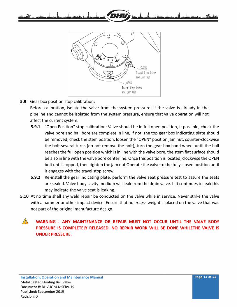
5.9 Gear box position stop calibration:
Before calibration, isolate the valve from the system pressure. If the valve is already in the
pipeline and cannot be isolated from the system pressure, ensure that valve operation will not
affect the current system.
5.9.1 ”Open Position” stop calibration: Valve should be in full open position, if possible, check the
valve bore and ball bore are complete in line, if not, the top gear box indicating plate should
be removed, check the stem position, loosen the “OPEN” position jam nut, counter-clockwise
the bolt several turns (do not remove the bolt), turn the gear box hand wheel until the ball
reaches the full open position which is in line with the valve bore, the stem flat surface should
be also in line with the valve bore centerline. Once this position is located, clockwise the OPEN
bolt until stopped, then tighten the jam nut Operate the valve to the fully closed position until
it engages with the travel stop screw.
5.9.2 Re-install the gear indicating plate, perform the valve seat pressure test to assure the seats
are sealed. Valve body cavity medium will leak from the drain valve. If it continues to leak this
may indicate the valve seat is leaking.
5.10 At no time shall any weld repair be conducted on the valve while in service. Never strike the valve
with a hammer or other impact device. Ensure that no excess weight is placed on the valve that was
not part of the original manufacture design.
WARNING ! ANY MAINTENANCE OR REPAIR MUST NOT OCCUR UNTIL THE VALVE BODY
PRESSURE IS COMPLETELY RELEASED. NO REPAIR WORK WILL BE DONE WHILETHE VALVE IS
UNDER PRESSURE.
Installation, Operation and Maintenance Manual Metal Seated Floating Ball Valve Document #: DHV-IOM-MSFBV-19 Published: September 2019
Revision: 0
Page 15 of 22
6. DETAILED DISASSEMBLY AND ASSEMBLY
6.1 METAL SEATED FLOATING BALL VALVE DISASSEMBLY
Metal seated floating ball valve shall be removed from pipeline before disassembling the valve, and the
valve must be in closed position, mark the direction and position on the parts. Assure any markings do not
disappear during the cleaning process; take care not to damage any parts (stamping of the ball or seats
may cause damage).
ATTENTION: Mark the valve seat and its matching ball sealing surface. Seats are not interchangeable, when
reassembling, the corresponding ball and seats must be installed together.
6.1.1 Lever operated valves, remove the locating and locking pin and the hand lever,
6.1.2 Gear operated valve, Remove the gear box fastener (nuts and washer) and remove the gear box.
6.1.3 Place the valve vertically on a clean surface, preferable a wood or plastic surface material to
assure protection for the flange sealing surface and to avoid damage to the RF or RTJ end
connection. Loosen and remove the body/end connection nuts, and then remove the end
connection and place the end connection vertically with flange facing downwards.
6.1.4 Remove the downstream seat from the ball and mark both the ball sealing surface and
downstream seat, if it is a bolted type downstream seat, the seat holding plate and screws must
be removed first, then remove the seat.
WARNING: do not damage the sealing surface of seat and ball, do not damage the seat support surface on
the end connection.
6.1.5 Remove the body/end connection bolting, and the body spiral wound gasket.
6.1.6 Carefully remove the ball from the body and avoid damaging the ball surface. mark the upstream
and downstream seat side in the stem/ball connection slot.
6.1.7 Remove the upstream seat and disc spring from the body.
6.1.8 Remove the gland bolts, Belleville washer and the gland flange.
6.1.9 If the valve is designed with an anti-blow out device, , push the stem (including thee thrust bearing),
towards the body cavity, to remove the anti-blow ring, pin, and stem thrust bearing, then remove
the stem out from the stem packing bore area. For 1 piece stem design, remove the stem and
thrust bearing from body cavity area.
6.1.10 Remove stem packing.
WARNING: Do not damage the surface of stem and packing bore area. This may cause stem leakage.
Installation, Operation and Maintenance Manual Metal Seated Floating Ball Valve Document #: DHV-IOM-MSFBV-19 Published: September 2019
Revision: 0
Page 16 of 22
6.2 METAL SEATED FLOATING BALL VALVE ASSEMBLY
6.2.1 Clean all parts, and replace any damaged parts with new replacement parts
6.2.2 Place the valve body vertically on a clean surface, assure that flange surfaces are not damaged.
6.2.3 Install the seat disc spring, upstream seat into the seat pocket area.
ATTENTION: use the marked upstream seat to install, do not mix the upstream and downstream seats.
6.2.4 For anti-blowout stem, install the stem from the body packing bore area, install the thrust
washer, and anti-blowout ring, line up the holes on the anti-blowout ring and the stem, insert
the pin through and then pull up the stem all the way up to correct location. For one piece
stem design, install the thrust washer from top of the stem all the way to the stem shoulder,
and then install the stem through body cavity area all the way through the bottom stem
packing bore and reach to the correct location.
6.2.5 Rotate the stem until the stem bottom flat face is parallel to the valve body bore, and then
install the ball (closed position) connecting to the stem/ball connection area.
WARNING: DO NOT DAMAGE THE BALL, SEAT, OR SEALING SURFACE
6.2.6 Install the new spiral wound body gasket and the body/end connection bolting.
6.2.7 Install the downstream seat to the end connection, if it is the bolted type seat, use the holding
plate and bolts to secure the seat.
6.2.8 Install the end connection/downstream seat to the valve body connection, make sure body
and end connection are connecting correctly, flat top matching to the body, and then tighten
the bolt/nut connections
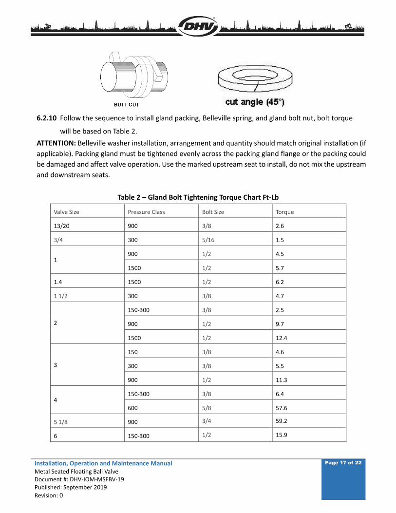
6.2.9 Install the new stem packing to the packing bore area. Note: Install packing rings one at a time,
the top and bottom rings are Inconel wound graphite packing, in between are the graphite
packing ring (flexible graphite), compress each ring with the packing gland before installing the
next one. Graphite packing ring may be cut by wrapping the packing around a round bar with
the same stem diameter as shown in figure below. Do not stretch the packing and use a sharp
knife to cut at 45°. The seam position between top and bottom packing ring shall be installed
at 180° apart. Graphite packing rings are one piece ring shaped, and install around the stem
and pushed into the packing bore into the valve body.
Installation, Operation and Maintenance Manual Metal Seated Floating Ball Valve Document #: DHV-IOM-MSFBV-19 Published: September 2019
Revision: 0
Page 17 of 22
6.2.10 Follow the sequence to install gland packing, Belleville spring, and gland bolt nut, bolt torque
will be based on Table 2.
ATTENTION: Belleville washer installation, arrangement and quantity should match original installation (if
applicable). Packing gland must be tightened evenly across the packing gland flange or the packing could
be damaged and affect valve operation. Use the marked upstream seat to install, do not mix the upstream
and downstream seats.
Table 2 – Gland Bolt Tightening Torque Chart Ft-Lb
Valve Size Pressure Class Bolt Size Torque
13/20 900 3/8 2.6
3/4 300 5/16 1.5
1 900 1/2 4.5
1500 1/2 5.7
1.4 1500 1/2 6.2
1 1/2 300 3/8 4.7
2
150-300 3/8 2.5
900 1/2 9.7
1500 1/2 12.4
3
150 3/8 4.6
300 3/8 5.5
900 1/2 11.3
4 150-300 3/8 6.4
600 5/8 57.6
5 1/8 900 3/4 59.2
6 150-300 1/2 15.9
Installation, Operation and Maintenance Manual Metal Seated Floating Ball Valve Document #: DHV-IOM-MSFBV-19 Published: September 2019
Revision: 0
Page 18 of 22
6.2.11 Install the mounting bracket to the valve body, tighten the mounting bracket bolt/nut to the
right torque. Continue installing the adapter sleeve (if required), bushing to the stem, driving
sleeve key (if required) etc.
6.2.12 For lever operated valve, install the connecting pin through the holes on the lever and the
stem, locking pin on the lever.
6.2.13 For gear operated valve, install the gear box to the mounting bracket, tighten the
bolt/nut/washer connection.
Installation, Operation and Maintenance Manual Metal Seated Floating Ball Valve Document #: DHV-IOM-MSFBV-19 Published: September 2019
Revision: 0
Page 19 of 22
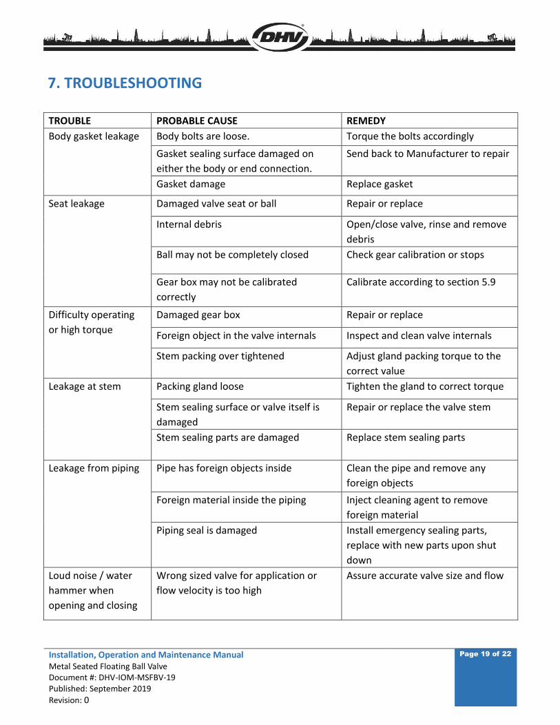
7. TROUBLESHOOTING
TROUBLE PROBABLE CAUSE REMEDY
Body gasket leakage Body bolts are loose. Torque the bolts accordingly
Gasket sealing surface damaged on
either the body or end connection.
Send back to Manufacturer to repair
Gasket damage Replace gasket
Seat leakage Damaged valve seat or ball Repair or replace
Internal debris Open/close valve, rinse and remove
debris
Ball may not be completely closed Check gear calibration or stops
Gear box may not be calibrated
correctly
Calibrate according to section 5.9
Difficulty operating
or high torque
Damaged gear box Repair or replace
Foreign object in the valve internals Inspect and clean valve internals
Stem packing over tightened Adjust gland packing torque to the
correct value
Leakage at stem Packing gland loose Tighten the gland to correct torque
Stem sealing surface or valve itself is
damaged
Repair or replace the valve stem
Stem sealing parts are damaged
Replace stem sealing parts
Leakage from piping Pipe has foreign objects inside
Clean the pipe and remove any
foreign objects
Foreign material inside the piping Inject cleaning agent to remove
foreign material
Piping seal is damaged Install emergency sealing parts,
replace with new parts upon shut
down
Loud noise / water
hammer when
opening and closing
Wrong sized valve for application or
flow velocity is too high
Assure accurate valve size and flow
Installation, Operation and Maintenance Manual Metal Seated Floating Ball Valve Document #: DHV-IOM-MSFBV-19 Published: September 2019
Revision: 0
Page 20 of 22
8. WARRANTY AND SERVICE
8.1 VALVE WARRANTY PERIOD
8.1.1 Valve warranty period is 12 months from the date shipped from the factory.
8.1.2 In the event the end user encounters an issue of quality, please notify DHV immediately. DHV reserve
the right to investigate and settle all issues of quality concerns directly with the end user. Refer to DHV’s
standard warranty policies for questions or concerns regarding warranty concerns.
8.1.3 Addressing a valve quality issue within the warranty period:
DHV reserves the right to review and respond to all requests for warranty repair or replacement, prior to
making any replacement or repairs by the end user.
8.1.4 DHV will not be held responsible for any damage due to natural disaster, such as earthquake,
hurricane etc. during valve shipment.
8.1.5 DHV must to be consulted for any warranty issue before being held responsible for any repairs or
valve replacement.
8.2 SERVICE
8.2.1 If required by the contract, DHV may provide and perform field installation and start up testing.
8.2.2 Upon end user request, DHV can provide services in monitoring the valve quality and history for Long
Term Ownership. Additionally, DHV can provide all the necessary training of repair services to the valve, as
well as training on safe valve operations.
APPENDIX I
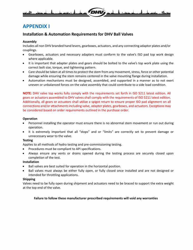
Installation & Automation Requirements for DHV Ball Valves
Assembly Includes all non DHV branded hand levers, gearboxes, actuators, and any connecting adaptor plates and/or couplings.
Gearboxes, actuators and necessary adapters must conform to the valve’s ISO pad top work design where applicable.
It is important that adapter plates and gears should be bolted to the valve’s top work plate using the correct bolt size, torque, and tightening pattern.
Care should be taken at all times to protect the stem from any movement, stress, force or other potential damage while ensuring the stem remains centered in the valve mounting flange during installation.
Automation mechanisms must be designed, assembled, and supported in a manner as to not exert uneven or unbalanced forces on the valve assembly that could contribute to a side load condition.
NOTE: DHV valve top works fully comply with the requirements set forth in ISO 5211 latest edition. All gears or actuators assembled to DHV valves shall comply with the requirements of ISO 5211 latest edition. Additionally, all gears or actuators shall utilize a spigot return to ensure proper ISO pad alignment on all connections and/or attachments including valve, adapter plates, gearboxes, and actuators. Exceptions may be considered based on order requirements outlined in the purchase order. Operation
Personnel installing the operator must ensure there is no abnormal stem movement or run out during operation.
It is extremely important that all “stops” and or “limits” are correctly set to prevent damage or unnecessary wear to the valve.
Testing Applies to all methods of hydro testing and pre-commissioning testing.
Procedures must be compliant to API specifications.
Always ensure any vents or drains opened during the testing process are securely closed upon completion of the test.
Installation
Ball valves are best suited for operation in the horizontal position.
Ball valves must always be either fully open, or fully closed once installed and are not designed or intended for throttling applications.
Shipping Valves need to be fully open during shipment and actuators need to be braced to support the extra weight at the top end of the valve.
Failure to follow these manufacturer prescribed requirements will void any warranties
Installation, Operation and Maintenance Manual Metal Seated Floating Ball Valve Document #: DHV-IOM-MSFBV-19 Published: September 2019
Revision: 0
Page 22 of 22
DHV Industries, Inc.
3451 Pegasus Drive
Bakersfield, CA 93308 USA
Call Toll Free: (833) DHV-USA1
Phone: (661) 392-8948
Fax: (661) 392-8947
E-mail:[email protected]
Website: www.dhvindustries.com
DHV Valve Company, Inc.
10401 South Sam Houston Pkwy West,
Houston, TX 77071 USA
Call Toll Free: (844) 828-2169
Phone: (346) 304-2968
Fax: (346) 304-2971
E-mail:[email protected]
Website: www.dhvvalve.com
DHV is committed to providing you with the necessary information to support our products. Our global
network of authorized service centers, technical support personnel and warranty support personnel are
ready to serve your needs for support on applications, products, service and warranty. Contact our USA
Bakersfield headquarters for immediate assistance to your support needs.