Embed Size (px)
Citation preview
1
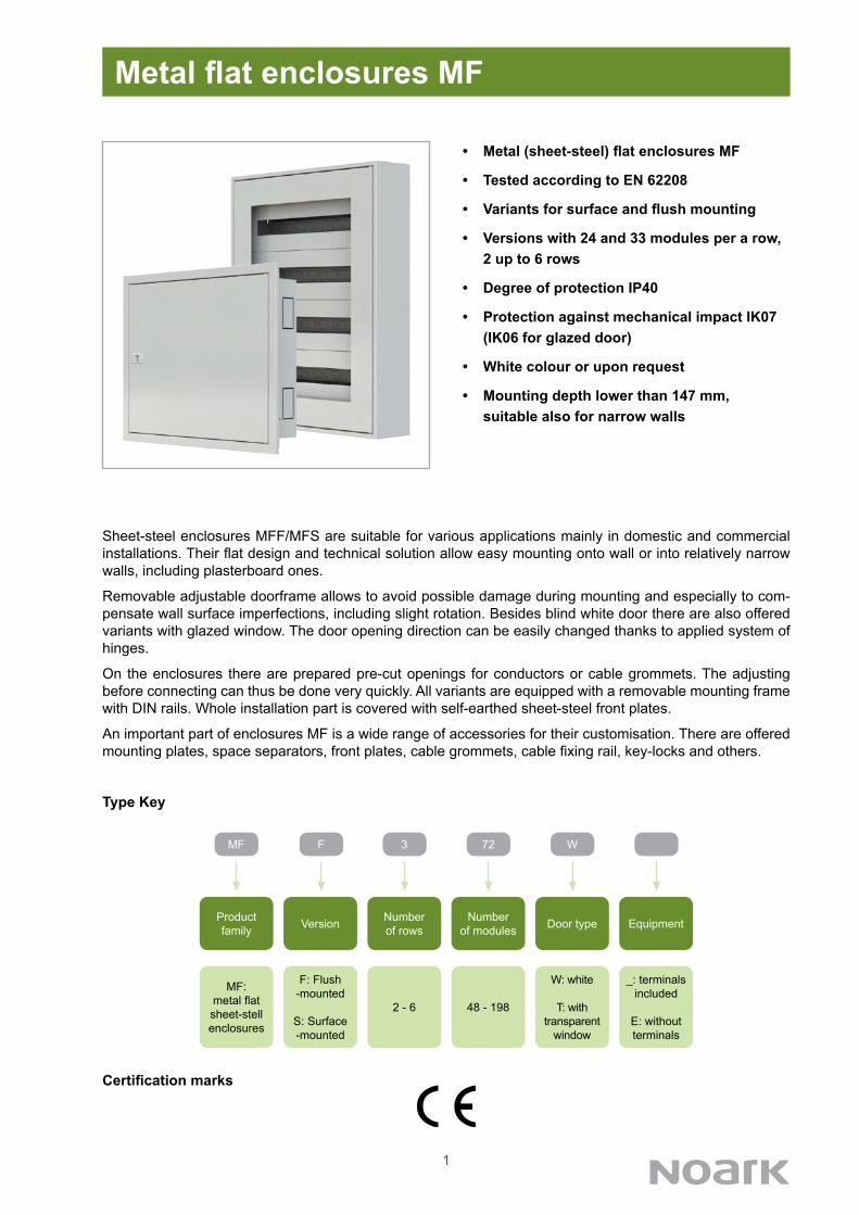
Metal flat enclosures MF
• Metal (sheet-steel) flat enclosures MF
• Tested according to EN 62208
• Variants for surface and flush mounting
• Versions with 24 and 33 modules per a row, 2 up to 6 rows
• Degree of protection IP40
• Protection against mechanical impact IK07 (IK06 for glazed door)
• White colour or upon request
• Mounting depth lower than 147 mm, suitable also for narrow walls
Sheet-steel enclosures MFF/MFS are suitable for various applications mainly in domestic and commercial installations. Their flat design and technical solution allow easy mounting onto wall or into relatively narrow walls, including plasterboard ones.
Removable adjustable doorframe allows to avoid possible damage during mounting and especially to com-pensate wall surface imperfections, including slight rotation. Besides blind white door there are also offered variants with glazed window. The door opening direction can be easily changed thanks to applied system of hinges.
On the enclosures there are prepared pre-cut openings for conductors or cable grommets. The adjusting before connecting can thus be done very quickly. All variants are equipped with a removable mounting frame with DIN rails. Whole installation part is covered with self-earthed sheet-steel front plates.
An important part of enclosures MF is a wide range of accessories for their customisation. There are offered mounting plates, space separators, front plates, cable grommets, cable fixing rail, key-locks and others.
MF
Product family
MF: metal flat sheet-stell enclosures
3
Numberof rows
2 - 6
Type Key
Certification marks
F
Version
F: Flush -mounted
S: Surface -mounted
72
Number of modules
48 - 198
W
Door type
W: white
T: with transparent
window
Equipment
_: terminalsincluded
E: without terminals
2
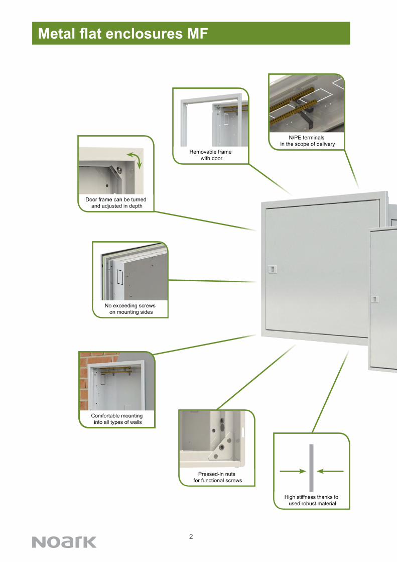
Metal flat enclosures MF
Door frame can be turned and adjusted in depth
Pressed-in nuts for functional screws
N/PE terminals in the scope of delivery
Removable frame with door
No exceeding screws on mounting sides
High stiffness thanks to used robust material
Comfortable mountinginto all types of walls

3
Metal flat enclosures MF
Pre-pressed openings for cable grommets
Standardized key-lock system
Wide range of accessories
Separate sheet-steelfront plates
Pre-cut openings for conductors
Easy change of door opening direction
4
Modules Number Total N+PE Article No. Type Packing per a row of rows modules terminals
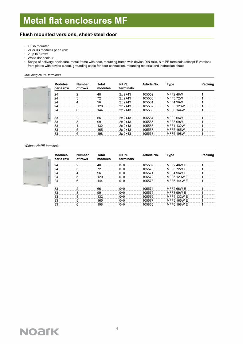
24 2 48 2x 2+43 105559 MFF2 48W 124 3 72 2x 2+43 105560 MFF3 72W 124 4 96 2x 2+43 105561 MFF4 96W 124 5 120 2x 2+43 105562 MFF5 120W 124 6 144 2x 2+43 105563 MFF6 144W 1
33 2 66 2x 2+43 105564 MFF2 66W 133 3 99 2x 2+43 105565 MFF3 99W 133 4 132 2x 2+43 105566 MFF4 132W 133 5 165 2x 2+43 105567 MFF5 165W 133 6 198 2x 2+43 105568 MFF6 198W 1
24 2 48 0+0 105569 MFF2 48W E 124 3 72 0+0 105570 MFF3 72W E 124 4 96 0+0 105571 MFF4 96W E 124 5 120 0+0 105572 MFF5 120W E 124 6 144 0+0 105573 MFF6 144W E 1
33 2 66 0+0 105574 MFF2 66W E 133 3 99 0+0 105575 MFF3 99W E 133 4 132 0+0 105576 MFF4 132W E 133 5 165 0+0 105577 MFF5 165W E 133 6 198 0+0 105865 MFF6 198W E 1
Modules Number Total N+PE Article No. Type Packing per a row of rows modules terminals
Flush mounted versions, sheet-steel door
• Flush mounted• 24 or 33 modules per a row• 2 up to 6 rows• White door colour • Scope of delivery: enclosure, metal frame with door, mounting frame with device DIN rails, N + PE terminals (except E version),
front plates with device cutout, grounding cable for door connection, mounting material and instruction sheet
Metal flat enclosures MF
Including N+PE terminals
Without N+PE terminals
5
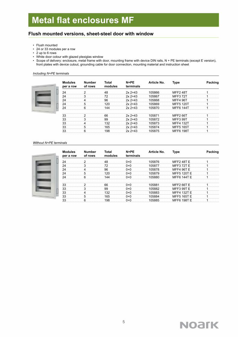
24 2 48 0+0 105876 MFF2 48T E 124 3 72 0+0 105877 MFF3 72T E 124 4 96 0+0 105878 MFF4 96T E 124 5 120 0+0 105879 MFF5 120T E 124 6 144 0+0 105880 MFF6 144T E 1
33 2 66 0+0 105881 MFF2 66T E 133 3 99 0+0 105882 MFF3 99T E 133 4 132 0+0 105883 MFF4 132T E 133 5 165 0+0 105884 MFF5 165T E 133 6 198 0+0 105885 MFF6 198T E 1
Modules Number Total N+PE Article No. Type Packing per a row of rows modules terminals
Modules Number Total N+PE Article No. Type Packing per a row of rows modules terminals
24 2 48 2x 2+43 105866 MFF2 48T 124 3 72 2x 2+43 105867 MFF3 72T 124 4 96 2x 2+43 105868 MFF4 96T 124 5 120 2x 2+43 105869 MFF5 120T 124 6 144 2x 2+43 105870 MFF6 144T 1
33 2 66 2x 2+43 105871 MFF2 66T 133 3 99 2x 2+43 105872 MFF3 99T 133 4 132 2x 2+43 105873 MFF4 132T 133 5 165 2x 2+43 105874 MFF5 165T 133 6 198 2x 2+43 105875 MFF6 198T 1
Flush mounted versions, sheet-steel door with window
• Flush mounted• 24 or 33 modules per a row• 2 up to 6 rows• White door colour with glazed plexiglas window• Scope of delivery: enclosure, metal frame with door, mounting frame with device DIN rails, N + PE terminals (except E version),
front plates with device cutout, grounding cable for door connection, mounting material and instruction sheet
Metal flat enclosures MF
Including N+PE terminals
Without N+PE terminals

6
Surface mounted versions, sheet-steel door
• Surface mounted• 24 or 33 modules per a row• 2 up to 6 rows• White door colour• Scope of delivery: enclosure, metal frame with door, mounting frame with device DIN rails, N + PE terminals (except E version),
front plates with device cutout, grounding cable for door connection, mounting material and instruction sheet
Metal flat enclosures MF
Modules Number Total N+PE Article No. Type Packing per a row of rows modules terminals
24 2 48 2x 2+43 105886 MFS2 48W 124 3 72 2x 2+43 105887 MFS3 72W 124 4 96 2x 2+43 105888 MFS4 96W 124 5 120 2x 2+43 105889 MFS5 120W 124 6 144 2x 2+43 105890 MFS6 144W 1
33 2 66 2x 2+43 105891 MFS2 66W 133 3 99 2x 2+43 105892 MFS3 99W 133 4 132 2x 2+43 105893 MFS4 132W 133 5 165 2x 2+43 105894 MFS5 165W 133 6 198 2x 2+43 105895 MFS6 198W 1
24 2 48 0+0 105896 MFS2 48W E 124 3 72 0+0 105897 MFS3 72W E 124 4 96 0+0 105898 MFS4 96W E 124 5 120 0+0 105899 MFS5 120W E 124 6 144 0+0 105900 MFS6 144W E 1
33 2 66 0+0 105901 MFS2 66W E 133 3 99 0+0 105902 MFS3 99W E 133 4 132 0+0 105903 MFS4 132W E 133 5 165 0+0 105904 MFS5 165W E 133 6 198 0+0 105905 MFS6 198W E 1
Modules Number Total N+PE Article No. Type Packing per a row of rows modules terminals
Including N+PE terminals
Without N+PE terminals

7
24 2 48 0+0 105916 MFS2 48T E 124 3 72 0+0 105917 MFS3 72T E 124 4 96 0+0 105918 MFS4 96T E 124 5 120 0+0 105919 MFS5 120T E 124 6 144 0+0 105920 MFS6 144T E 1
33 2 66 0+0 105921 MFS2 66T E 133 3 99 0+0 105922 MFS3 99T E 133 4 132 0+0 105923 MFS4 132T E 133 5 165 0+0 105924 MFS5 165T E 133 6 198 0+0 105925 MFS6 198T E 1
Modules Number Total N+PE Article No. Type Packing per a row of rows modules terminals
Modules Number Total N+PE Article No. Type Packing per a row of rows modules terminals
24 2 48 2x 2+43 105906 MFS2 48T 124 3 72 2x 2+43 105907 MFS3 72T 124 4 96 2x 2+43 105908 MFS4 96T 124 5 120 2x 2+43 105909 MFS5 120T 124 6 144 2x 2+43 105910 MFS6 144T 1
33 2 66 2x 2+43 105911 MFS2 66T 133 3 99 2x 2+43 105912 MFS3 99T 133 4 132 2x 2+43 105913 MFS4 132T 133 5 165 2x 2+43 105914 MFS5 165T 133 6 198 2x 2+43 105915 MFS6 198T 1
Surface mounted versions, sheet-steel door with window
• Surface mounted• 24 or 33 modules per a row• 2 up to 6 rows• White door colour with glazed plexiglas window• Scope of delivery: enclosure, metal frame with door, mounting frame with device DIN rails, N + PE terminals (except E version),
front plates with device cutout, grounding cable for door connection, mounting material and instruction sheet
Metal flat enclosures MF
Including N+PE terminals
Without N+PE terminals

8
24 2 48 105936 MFF DR2 48T 124 3 72 105937 MFF DR3 72T 124 4 96 105938 MFF DR4 96T 124 5 120 105939 MFF DR5 120T 124 6 144 105940 MFF DR6 144T 1
33 2 66 105941 MFF DR2 66T 133 3 99 105942 MFF DR3 99T 133 4 132 105943 MFF DR4 132T 133 5 165 105944 MFF DR5 165T 133 6 198 105945 MFF DR6 198T 1
Modules Number Total Article No. Type Packing per a row of rows modules
Modules Number Total Article No. Type Packing per a row of rows modules
24 2 48 105926 MFF DR2 48W 124 3 72 105927 MFF DR3 72W 124 4 96 105928 MFF DR4 96W 124 5 120 105929 MFF DR5 120W 124 6 144 105930 MFF DR6 144W 1
33 2 66 105931 MFF DR2 66W 133 3 99 105932 MFF DR3 99W 133 4 132 105933 MFF DR4 132W 133 5 165 105934 MFF DR5 165W 133 6 198 105935 MFF DR6 198W 1
Spare door
• Spare door with plastic lock for flush mounted enclosures• 24 or 33 modules per a row• 2 up to 6 rows• White coloured sheet-steel parts of door • Plexiglas window material• Packed separately • Door hinges are not included
Metal flat enclosures MF
White door
Door with glazed window
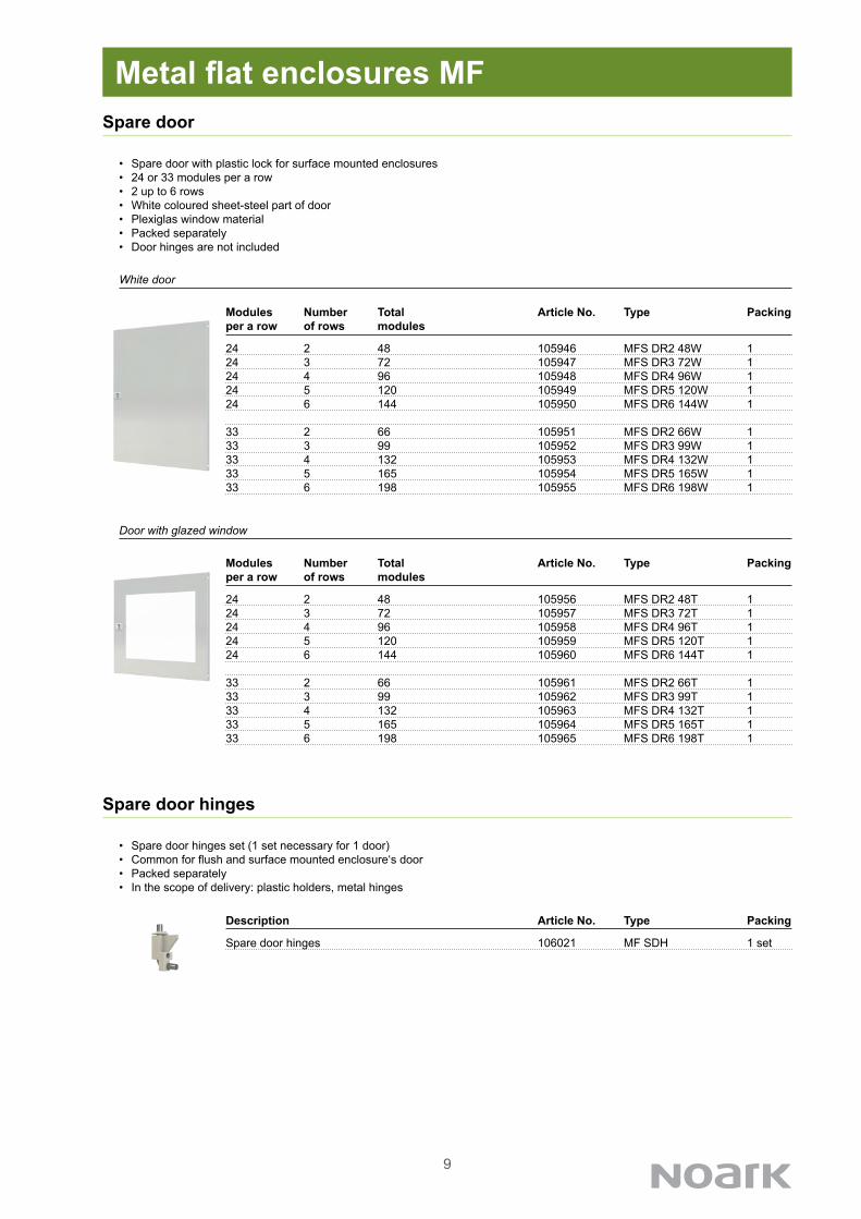
Description Article No. Type Packing
Spare door hinges 106021 MF SDH 1 set
Spare door hinges
• Spare door hinges set (1 set necessary for 1 door)• Common for flush and surface mounted enclosure‘s door• Packed separately• In the scope of delivery: plastic holders, metal hinges
9
24 2 48 105956 MFS DR2 48T 124 3 72 105957 MFS DR3 72T 124 4 96 105958 MFS DR4 96T 124 5 120 105959 MFS DR5 120T 124 6 144 105960 MFS DR6 144T 1
33 2 66 105961 MFS DR2 66T 133 3 99 105962 MFS DR3 99T 133 4 132 105963 MFS DR4 132T 133 5 165 105964 MFS DR5 165T 133 6 198 105965 MFS DR6 198T 1
Modules Number Total Article No. Type Packing per a row of rows modules
Modules Number Total Article No. Type Packing per a row of rows modules
24 2 48 105946 MFS DR2 48W 124 3 72 105947 MFS DR3 72W 124 4 96 105948 MFS DR4 96W 124 5 120 105949 MFS DR5 120W 124 6 144 105950 MFS DR6 144W 1
33 2 66 105951 MFS DR2 66W 133 3 99 105952 MFS DR3 99W 133 4 132 105953 MFS DR4 132W 133 5 165 105954 MFS DR5 165W 133 6 198 105955 MFS DR6 198W 1
Spare door
• Spare door with plastic lock for surface mounted enclosures• 24 or 33 modules per a row• 2 up to 6 rows• White coloured sheet-steel part of door • Plexiglas window material• Packed separately • Door hinges are not included
Metal flat enclosures MF
White door
Door with glazed window
Description Article No. Type Packing
Spare door hinges 106021 MF SDH 1 set
Spare door hinges
• Spare door hinges set (1 set necessary for 1 door)• Common for flush and surface mounted enclosure‘s door• Packed separately• In the scope of delivery: plastic holders, metal hinges
10
Description Modules Height Article No. Type Packing per a row
Standard plate 24 141 mm 105966 MF FP 1 24 1Wide outer plate 24 212 mm 105968 MF FP 1+ 24 1
Standard plate 33 141 mm 105967 MF FP 1 33 1Wide outer plate 33 212 mm 105969 MF FP 1+ 33 1
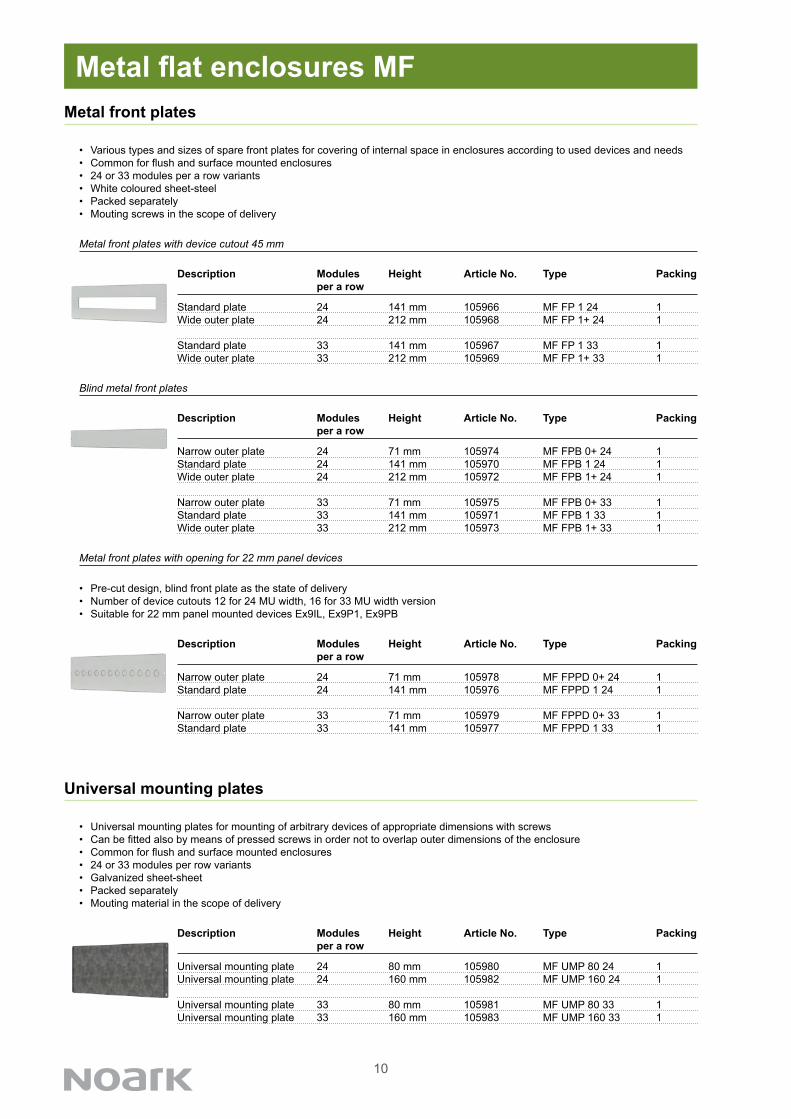
Metal front plates
• Various types and sizes of spare front plates for covering of internal space in enclosures according to used devices and needs• Common for flush and surface mounted enclosures• 24 or 33 modules per a row variants• White coloured sheet-steel• Packed separately• Mouting screws in the scope of delivery
Metal flat enclosures MF
Metal front plates with device cutout 45 mm
Description Modules Height Article No. Type Packing per a row
Narrow outer plate 24 71 mm 105974 MF FPB 0+ 24 1Standard plate 24 141 mm 105970 MF FPB 1 24 1Wide outer plate 24 212 mm 105972 MF FPB 1+ 24 1
Narrow outer plate 33 71 mm 105975 MF FPB 0+ 33 1Standard plate 33 141 mm 105971 MF FPB 1 33 1Wide outer plate 33 212 mm 105973 MF FPB 1+ 33 1
Blind metal front plates
Description Modules Height Article No. Type Packing per a row
Narrow outer plate 24 71 mm 105978 MF FPPD 0+ 24 1Standard plate 24 141 mm 105976 MF FPPD 1 24 1
Narrow outer plate 33 71 mm 105979 MF FPPD 0+ 33 1Standard plate 33 141 mm 105977 MF FPPD 1 33 1
Metal front plates with opening for 22 mm panel devices
• Pre-cut design, blind front plate as the state of delivery• Number of device cutouts 12 for 24 MU width, 16 for 33 MU width version• Suitable for 22 mm panel mounted devices Ex9IL, Ex9P1, Ex9PB
Description Modules Height Article No. Type Packing per a row
Universal mounting plate 24 80 mm 105980 MF UMP 80 24 1Universal mounting plate 24 160 mm 105982 MF UMP 160 24 1
Universal mounting plate 33 80 mm 105981 MF UMP 80 33 1Universal mounting plate 33 160 mm 105983 MF UMP 160 33 1
Universal mounting plates
• Universal mounting plates for mounting of arbitrary devices of appropriate dimensions with screws• Can be fitted also by means of pressed screws in order not to overlap outer dimensions of the enclosure• Common for flush and surface mounted enclosures• 24 or 33 modules per row variants• Galvanized sheet-sheet• Packed separately• Mouting material in the scope of delivery

11
Description Modules Article No. Type Packing per row
For vertically mounted Ex9M1 3P 24 105986 MF FP M1V 3P 24 1For vertically mounted Ex9M1 4P 24 105988 MF FP M1V 4P 24 1For vertically mounted Ex9M2 3P 24 105990 MF FP M2V 3P 24 1For vertically mounted Ex9M2 4P 24 105992 MF FP M2V 4P 24 1For horizontally mounted Ex9M1 3P 24 105987 MF FP M1H 3P 24 1For horizontaly mounted Ex9M1 4P 24 105989 MF FP M1H 4P 24 1For horizontaly mounted Ex9M2 3P 24 105991 MF FP M2H 3P 24 1
For vertically mounted Ex9M1 3P 33 105994 MF FP M1V 3P 33 1For vertically mounted Ex9M1 4P 33 105996 MF FP M1V 4P 33 1For vertically mounted Ex9M2 3P 33 105998 MF FP M2V 3P 33 1For vertically mounted Ex9M2 4P 33 106000 MF FP M2V 4P 33 1For horizontally mounted Ex9M1 3P 33 105995 MF FP M1H 3P 33 1For horizontally mounted Ex9M1 4P 33 105997 MF FP M1H 4P 33 1For horizontally mounted Ex9M2 3P 33 105999 MF FP M2H 3P 33 1
Metal front plates for MCCBs Ex9M
• Pre-cut front plate for MCCB of Ex9M line mounted in vertical and horizontal position• Common for flush and surface mounted enclosures• 24 or 33 modules per row variants• Front plate height 141 mm• White coloured sheet-steel• Packed separately• Mouting material in the scope of delivery
Metal flat enclosures MF
Description Modules Article No. Type Packing per row
Mounting plate for MCCBs 24 105984 MF MP M12 24 1
Mounting plate for MCCBs 33 105985 MF MP M12 33 1
Mounting plates for MCCBs line Ex9M
• Tailored pre-drilled mounting plates for mounting of MCCBs of Ex9M line, frame sizes M1 and M2• Mounting holes with thread for easy mounting of Ex9M1 and Ex9M2• In case common mounting depth of the M1 size breaker‘s front panel is requested,
it is necessary to use mounting depth spacers WG 10• Common for flush and surface mounted enclosures• 24 or 33 modules per row variants• Galvanized sheet-sheet• Packed separately• Mounting material in the scope of delivery
Mounting depth spacers for mounting of M1 size MCCB• Set of mounting depth spacers for compensation of differences in height between frame sizes M1 and M2• Assure the same position of front panel towards front plate• Height 10 mm to fit M1 size of MCCBs with front plates MF FP M1
Mounting depth spacers M1 10 mm 106321 WG 10 1 set
Description Frame size Height Article No. Type Packing
12
Description Modules Article No. Type Packing per a row
Cable fixing rail 24 106019 MF CFR24 1
Cable fixing rail 33 106020 MF CFR33 1
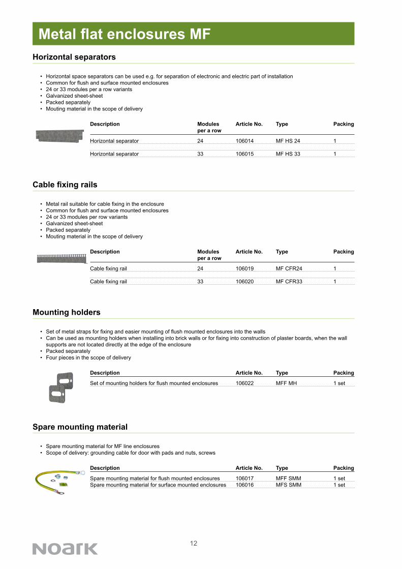
Cable fixing rails
• Metal rail suitable for cable fixing in the enclosure• Common for flush and surface mounted enclosures• 24 or 33 modules per row variants• Galvanized sheet-sheet• Packed separately• Mouting material in the scope of delivery
Metal flat enclosures MF
Description Article No. Type Packing
Set of mounting holders for flush mounted enclosures 106022 MFF MH 1 set
Mounting holders
• Set of metal straps for fixing and easier mounting of flush mounted enclosures into the walls• Can be used as mounting holders when installing into brick walls or for fixing into construction of plaster boards, when the wall
supports are not located directly at the edge of the enclosure• Packed separately• Four pieces in the scope of delivery
Description Modules Article No. Type Packing per a row
Horizontal separator 24 106014 MF HS 24 1
Horizontal separator 33 106015 MF HS 33 1
Horizontal separators
• Horizontal space separators can be used e.g. for separation of electronic and electric part of installation• Common for flush and surface mounted enclosures• 24 or 33 modules per a row variants• Galvanized sheet-sheet• Packed separately• Mouting material in the scope of delivery
Description Article No. Type Packing
Spare mounting material for flush mounted enclosures 106017 MFF SMM 1 setSpare mounting material for surface mounted enclosures 106016 MFS SMM 1 set
Spare mounting material
• Spare mounting material for MF line enclosures• Scope of delivery: grounding cable for door with pads and nuts, screws
13
Metal flat enclosures MF
square socket, 6 mm 106826 MF DLK SQ6 1 set
square pin, 6 mm 106863 MF DLK SP6 1 set
double bit, 3 mm pin 106825 MF DLK DB3 1 set
double bit, 5 mm pin 106828 MF DLK DB5 1 set
slotted 2x4mm 106829 MF DLK S24 1 set
Czech crescent 106827 MF DLK CZ 1 set
Daimler-Benz 106830 MF DLK D 1 set
Insert Article No. Type Packing shape
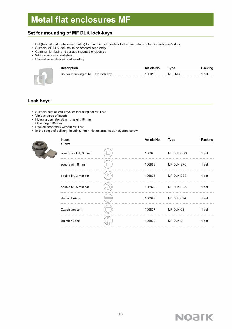
Lock-keys
• Suitable sets of lock-keys for mounting set MF LMS• Various types of inserts• Housing diameter 28 mm, height 18 mm• Cam length 35 mm• Packed separately without MF LMS• In the scope of delivery: housing, insert, flat external seal, nut, cam, screw
Description Article No. Type Packing
Set for mounting of MF DLK lock-key 106018 MF LMS 1 set
Set for mounting of MF DLK lock-keys
• Set (two tailored metal cover plates) for mounting of lock-key to the plastic lock cutout in enclosure‘s door• Suitable MF DLK lock-key to be ordered separately• Common for flush and surface mounted enclosures• White coloured sheet-steel• Packed separately without lock-key
14
Description Modules per row Article No. Type Packing
Spare single DIN rail 24 106002 MF DIN24 1
Spare single DIN rail 33 106003 MF DIN33 1
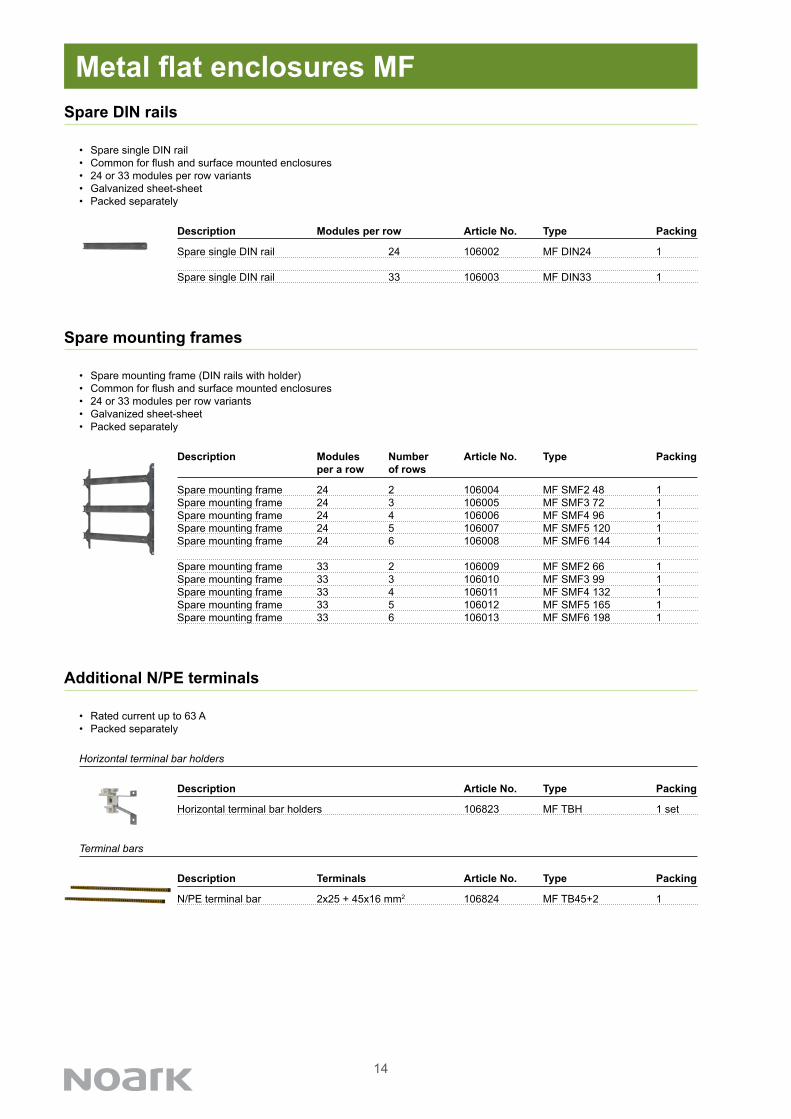
Spare DIN rails
• Spare single DIN rail• Common for flush and surface mounted enclosures• 24 or 33 modules per row variants• Galvanized sheet-sheet• Packed separately
Metal flat enclosures MF
Description Modules Number Article No. Type Packing per a row of rows
Spare mounting frame 24 2 106004 MF SMF2 48 1Spare mounting frame 24 3 106005 MF SMF3 72 1Spare mounting frame 24 4 106006 MF SMF4 96 1Spare mounting frame 24 5 106007 MF SMF5 120 1Spare mounting frame 24 6 106008 MF SMF6 144 1
Spare mounting frame 33 2 106009 MF SMF2 66 1Spare mounting frame 33 3 106010 MF SMF3 99 1Spare mounting frame 33 4 106011 MF SMF4 132 1Spare mounting frame 33 5 106012 MF SMF5 165 1Spare mounting frame 33 6 106013 MF SMF6 198 1
Spare mounting frames
• Spare mounting frame (DIN rails with holder) • Common for flush and surface mounted enclosures• 24 or 33 modules per row variants• Galvanized sheet-sheet• Packed separately
Horizontal terminal bar holders 106823 MF TBH 1 set
Description Article No. Type Packing
Additional N/PE terminals
• Rated current up to 63 A• Packed separately
Horizontal terminal bar holders
N/PE terminal bar 2x25 + 45x16 mm2 106824 MF TB45+2 1
Description Terminals Article No. Type Packing
Terminal bars

15
• Rated current up to 63 A• Rated operational voltage 690 V AC• All side finger-safe• One-side closed conductor notch• Plastic DIN-rail clip• For wires up to 16 mm2
7 up to 16 mm² blue 103850 TBB 7x16 1/107 up to 16 mm² green 103851 TBG 7x16 1/1015 up to 16 mm² blue 103852 TBB 15x16 1/1015 up to 16 mm² green 103853 TBG 15x16 1/10
Terminals Terminal Colour Article Type Packing capacity No.
Covered neutral and grounding terminal bars
• Rated current up to 63 A• Rated operational voltage 690 V AC• Plastic DIN-rail clip• For wires up to 10 mm2
7 10 mm² blue 103854 TBB 7x10 1/107 10 mm² green 103855 TBG 7x10 1/1012 10 mm² blue 103856 TBB 12x10 1/1012 10 mm² green 103857 TBG 12x10 1/10
Terminals Terminal Colour Article Type Packing capacity No.
Uncovered neutral and grounding terminal bars
• Rated current up to 63 A• Rated operational voltage 690 V AC• Steel-sheet DIN-rail clip, self-earthed• For wires up to 10 mm2
7 10 mm² 103858 TB 7x10 1/1012 10 mm² 103859 TB 12x10 1/10
Terminals Terminal Article Type Packing capacity No.
Terminal bars up to 63 A with steel DIN rail clip
Metal flat enclosures MF

16
Plastic cover for unused 45 mm device cutout 101574 B CC45 1/500
Description Article No. Type Packing
Plastic cover for empty place
• Plastic cover for unused 45 mm device cutouts• Total width 224 mm, can be shortened• Segmented as 1x 15 mm, 22 x 1/2 module width, 1x 15 mm• White colour plastic• Packed separately
Metal flat enclosures MF
Self-adhesive documentation pocket A4 106831 MF PDP A4 1Self-adhesive documentation pocket, slim A4 106832 MF PDP A4S 1
Description Size Article No. Type Packing
Plastic documentation pocket
• Self-adhesive pocket for documentation• Suitable for A4 paper size documents• Two versions according to number of pages• PVC material• Packed separately
Cable grommet for MFS enclosures 16 mm 106860 CGQS M16 1Cable grommet 20 mm 106208 CGQS M20 1Cable grommet 25 mm 106209 CGQS M25 1Cable grommet 32 mm 106210 CGQS M32 1
Description Diameter Article No. Type Packing
Cable grommets
• Cable grommets suitable for cutouts prepared on the topside of surface mounted enclosures• Top panels of MFS enclosures are pre-cut for 16 mm diameter grommets• Used material allows to use various diameter of the conductors (up to 50 mm2)• Packed separately
17
Special colour on request
• Enclosures MF can be produced in non-standard colours• Standards RAL codes can be chosen• Please contact NOARK staff with specification, based on which real possibility will be checked
Metal flat enclosures MF
Special version on request
• Enclosures MF can be produced in modified design• Changes must not affect general parameters of the enclosure• Typical changes - e.g. non-standard dimensions (within the range of smallest and biggest type), different internal configuration, etc.• Please contact NOARK staff with specification, based on which real possibility will be checked
Empty type label for distribution boards, self-adhesive 107841 MF TL 10
Description Article No. Type Packing
Type label
• Pre-printed type label for distribution boards according to EN 61439• Box texts in EN, CZ, SK, PL, RO, DE, FR, RU, UK, BG, HR, HU, IT, LT, LV, EE language• Material: Aluminium foil, resistive to chemical cleaners• Self-adhesive
. . 201
IEC / EN
Ue
IP
In
Producer / Výrobce / Výrobca / Prefabrykator / Producător / Hersteller / Producteur / Производитель / Виробник / Производител / Proizvođač / Berendezésgyártó / Produttore / Productor / Gamintojas / Ražotājs / Tootja
typovy_stitek.indd 1 17.7.2014 8:10:47
18
Technical Data MF
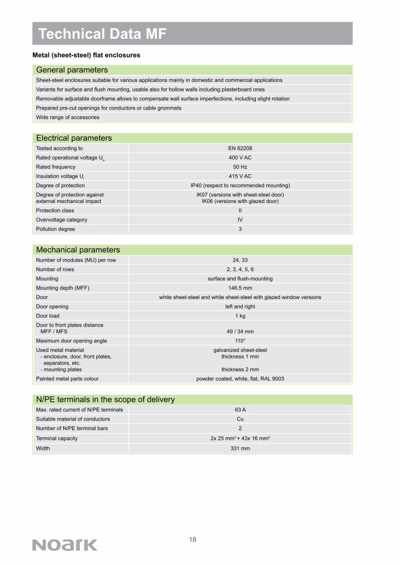
General parameters
Tested according to EN 62208
Rated operational voltage Ue 400 V AC
Rated frequency 50 Hz
Insulation voltage Ui 415 V AC
Degree of protection IP40 (respect to recommended mounting)
Degree of protection againstexternal mechanical impact
IK07 (versions with sheet-steel door)IK06 (versions with glazed door)
Protection class II
Overvoltage category IV
Pollution degree 3
Electrical parameters
Number of modules (MU) per row 24, 33
Number of rows 2, 3, 4, 5, 6
Mounting surface and flush-mounting
Mounting depth (MFF) 146.5 mm
Door white sheet-steel and white sheet-steel with glazed window versions
Door opening left and right
Door load 1 kg
Door to front plates distance MFF / MFS 49 / 34 mm
Maximum door opening angle 110°
Used metal material - enclosure, door, front plates, separators, etc. - mounting plates
galvanized sheet-steelthickness 1 mm
thickness 2 mm
Painted metal parts colour powder coated, white, flat, RAL 9003
Mechanical parameters
Metal (sheet-steel) flat enclosures
Max. rated current of N/PE terminals 63 A
Suitable material of conductors Cu
Number of N/PE terminal bars 2
Terminal capacity 2x 25 mm2 + 43x 16 mm2
Width 331 mm
N/PE terminals in the scope of delivery
Sheet-steel enclosures suitable for various applications mainly in domestic and commercial applications
Variants for surface and flush mounting, usable also for hollow walls including plasterboard ones
Removable adjustable doorframe allows to compensate wall surface imperfections, including slight rotation
Prepared pre-cut openings for conductors or cable grommets
Wide range of accessories
19
Technical Data MFMetal (sheet-steel) flat enclosures
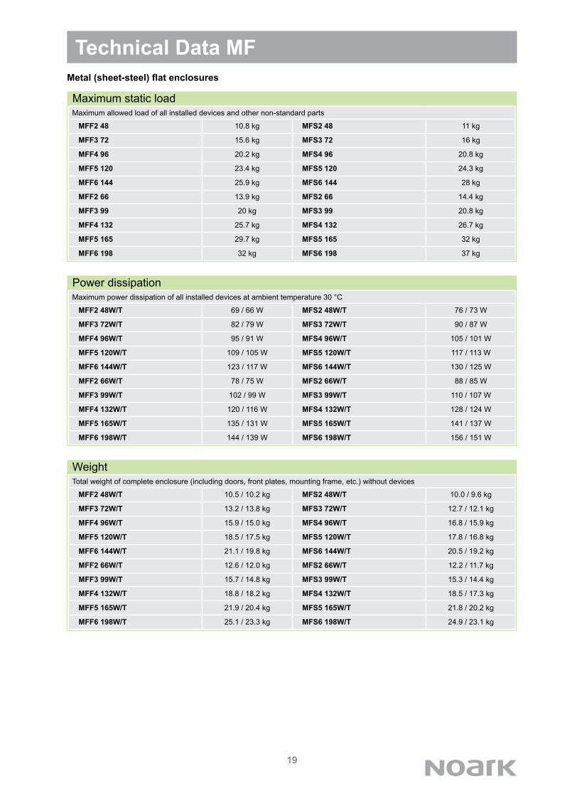
Maximum power dissipation of all installed devices at ambient temperature 30 °C
MFF2 48W/T 69 / 66 W MFS2 48W/T 76 / 73 W
MFF3 72W/T 82 / 79 W MFS3 72W/T 90 / 87 W
MFF4 96W/T 95 / 91 W MFS4 96W/T 105 / 101 W
MFF5 120W/T 109 / 105 W MFS5 120W/T 117 / 113 W
MFF6 144W/T 123 / 117 W MFS6 144W/T 130 / 125 W
MFF2 66W/T 78 / 75 W MFS2 66W/T 88 / 85 W
MFF3 99W/T 102 / 99 W MFS3 99W/T 110 / 107 W
MFF4 132W/T 120 / 116 W MFS4 132W/T 128 / 124 W
MFF5 165W/T 135 / 131 W MFS5 165W/T 141 / 137 W
MFF6 198W/T 144 / 139 W MFS6 198W/T 156 / 151 W
Power dissipation
Maximum static loadMaximum allowed load of all installed devices and other non-standard parts
MFF2 48 10.8 kg MFS2 48 11 kg
MFF3 72 15.6 kg MFS3 72 16 kg
MFF4 96 20.2 kg MFS4 96 20.8 kg
MFF5 120 23.4 kg MFS5 120 24.3 kg
MFF6 144 25.9 kg MFS6 144 28 kg
MFF2 66 13.9 kg MFS2 66 14.4 kg
MFF3 99 20 kg MFS3 99 20.8 kg
MFF4 132 25.7 kg MFS4 132 26.7 kg
MFF5 165 29.7 kg MFS5 165 32 kg
MFF6 198 32 kg MFS6 198 37 kg
WeightTotal weight of complete enclosure (including doors, front plates, mounting frame, etc.) without devices
MFF2 48W/T 10.5 / 10.2 kg MFS2 48W/T 10.0 / 9.6 kg
MFF3 72W/T 13.2 / 13.8 kg MFS3 72W/T 12.7 / 12.1 kg
MFF4 96W/T 15.9 / 15.0 kg MFS4 96W/T 16.8 / 15.9 kg
MFF5 120W/T 18.5 / 17.5 kg MFS5 120W/T 17.8 / 16.8 kg
MFF6 144W/T 21.1 / 19.8 kg MFS6 144W/T 20.5 / 19.2 kg
MFF2 66W/T 12.6 / 12.0 kg MFS2 66W/T 12.2 / 11.7 kg
MFF3 99W/T 15.7 / 14.8 kg MFS3 99W/T 15.3 / 14.4 kg
MFF4 132W/T 18.8 / 18.2 kg MFS4 132W/T 18.5 / 17.3 kg
MFF5 165W/T 21.9 / 20.4 kg MFS5 165W/T 21.8 / 20.2 kg
MFF6 198W/T 25.1 / 23.3 kg MFS6 198W/T 24.9 / 23.1 kg

20
Technical Data MFMetal (sheet-steel) flat enclosures
Front plates in the scope of delivery
Pre-cut openings for conductors or cable grommets - flush-mounted versions MFF2 48 MFF3 72 MFF4 96 MFF5 120
2x 47x85 mm (back side, center)+ 4x 47x85 mm (top)+ 4x 47x85 mm (bottom)+ 2x 47x85 mm (left-hand side) + 2x 47x85 mm (right-hand side)
MFF6 144 2x 47x85 mm (back side, center)+ 4x 47x85 mm (top)+ 4x 47x85 mm (bottom)+ 2x 47x85 mm (left-hand side) + 2x 47x85 mm (right-hand side)
MFF2 66 MFF3 99 MFF4 132 MFF5 165
2x 47x85 mm (back side, center)+ 5x 47x85 mm (top)+ 5x 47x85 mm (bottom)+ 2x 47x85 mm (left-hand side) + 2x 47x85 mm (right-hand side)
MFF6 198 2x 47x85 mm (back side, center)+ 5x 47x85 mm (top)+ 5x 47x85 mm (bottom)+ 3x 47x85 mm (left-hand side) + 3x 47x85 mm (right-hand side)
MFF3/MFS3 MFF4/MFS4 MFF5/MFS5 MFF6/MFS6 MFF2/MFS2
Pre-cut openings for conductors or cable grommets - surface-mounted versions all MFS variants 4x 47x55.6 mm (back side, center)
+ 4x 47x85 mm (back size, corners)+ 14x round Ø16 mm (top)

21
Dimensional drawings - flush-mounted versions
Technical Data MF
DimensionsType Dimensions [mm]
Width (X)
Height(Y)
Mounting depth
(Z)
Door width
(A)
Door height
(B)
Wall opening width (C)
Wall opening
height (D) MFF2 48 610.1 497 139 554 440 576 463
MFF3 72 610.1 638 139 554 581 576 604
MFF4 96 610.1 779 139 554 722 576 745
MFF5 120 610.1 920 139 554 863 576 886
MFF6 144 610.1 1061 139 554 1004 576 1027
MFF2 66 774.1 497 139 718 440 740 463
MFF3 99 774.1 638 139 718 581 740 604
MFF4 132 774.1 779 139 718 722 740 745
MFF5 165 774.1 920 139 718 863 740 886
MFF6 198 774.1 1061 139 718 1004 740 1027
Metal (sheet-steel) flat enclosures
Z 1,98
Y
A
B
6
47
6 55,60
47 14
52
85
34
22
7,50
35
30
17
26
56
60 77,50
X
45,50 80,50
45
136
,50
141
89
23
ŘEZ A-A MĚŘÍTKO 1 : 5
Z 12 7,50
Y
D
B
A 62 4,50
13,
50
9,80
X C
40 85
13
47
141
50,50 100,50
40
125
,50
89
23
ŘEZ B-B MĚŘÍTKO 1 : 5
ASV.RIN.496HMOTNOST:
A0
LIST 1 Z 1 LISTŮMĚŘÍTKO:1:2
Č. VÝKRESU
NÁZEV:
ZMĚNANEUPRAVOVAT MĚŘÍTKO VÝKRESU
MATERIÁL:
DATUMPODPISJMÉNO
ODSTRANITOSTRÉ HRANY
OPRACOVÁNÍ:NENÍ-LI UVEDENO JINAK:JEDNOTKY JSOU V MILIMETRECHDRSNOST:TOLERANCE: LINEÁRNÍ: ÚHLOVÁ:
Z. JAKOSTI
VÝROBA
SCHVÁLIL
PŘEZKOUŠEL
NAVRHL

22
Dimensional drawings - surface-mounted versions
Z 1,98
Y
A B
6
47
6 55,60
47 14
52
85
34
22
7,50
35
30
17
26
56
60 77,50
X
45,50 80,50
45
136
,50
141
89
23
ŘEZ A-A MĚŘÍTKO 1 : 5
Z 12 7,50
Y
D
B
A 62 4,50
13,
50
9,80
X C
40 85
13
47
141
50,50 100,50
40
125
,50
89
23
ŘEZ B-B MĚŘÍTKO 1 : 5
ASV.RIN.496HMOTNOST:
A0
LIST 1 Z 1 LISTŮMĚŘÍTKO:1:2
Č. VÝKRESU
NÁZEV:
ZMĚNANEUPRAVOVAT MĚŘÍTKO VÝKRESU
MATERIÁL:
DATUMPODPISJMÉNO
ODSTRANITOSTRÉ HRANY
OPRACOVÁNÍ:NENÍ-LI UVEDENO JINAK:JEDNOTKY JSOU V MILIMETRECHDRSNOST:TOLERANCE: LINEÁRNÍ: ÚHLOVÁ:
Z. JAKOSTI
VÝROBA
SCHVÁLIL
PŘEZKOUŠEL
NAVRHL
Technical Data MF
DimensionsType Dimensions [mm]
Width (X)
Height(Y)
Depth(Z)
Door width(A)
Door height(B)
MFS2 48 586 451 136 556 420
MFS3 72 586 592 136 556 561
MFS4 96 586 733 136 556 702
MFS5 120 586 874 136 556 843
MFS6 144 586 1115 136 556 984
MFS2 66 750 451 136 720 420
MFS3 99 750 592 136 720 561
MFS4 132 750 733 136 720 702
MFS5 165 750 874 136 720 843
MFS6 198 750 1115 136 720 984
Metal (sheet-steel) flat enclosures
23
Technical Data MFMetal (sheet-steel) flat enclosures - description of technical solution
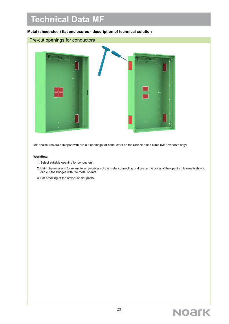
Pre-cut openings for conductors
MF enclosures are equipped with pre-cut openings for conductors on the rear side and sides (MFF variants only).
Workflow:
1. Select suitable opening for conductors.
2. Using hammer and for example screwdriver cut the metal connecting bridges on the cover of the opening. Alternatively you can cut the bridges with the metal shears.
3. For breaking of the cover use flat pliers.
24
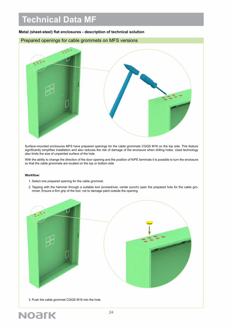
Surface-mounted enclosures MFS have prepared openings for the cable grommets CGQS M16 on the top side. This feature significantly simplifies installation and also reduces the risk of damage of the enclosure when drilling holes. Used technology also limits the size of unpainted surface of the hole.
With the ability to change the direction of the door opening and the position of N/PE terminals it is possible to turn the enclosure so that the cable grommets are located on the top or bottom side.
Workflow:
1. Select one prepared opening for the cable grommet.
2. Tapping with the hammer through a suitable tool (screwdriver, center punch) open the prepared hole for the cable gro-mmet. Ensure a firm grip of the tool, not to damage paint outside the opening.
3. Push the cable grommet CGQS M16 into the hole.
Technical Data MF
Prepared openings for cable grommets on MFS versions
Metal (sheet-steel) flat enclosures - description of technical solution
25
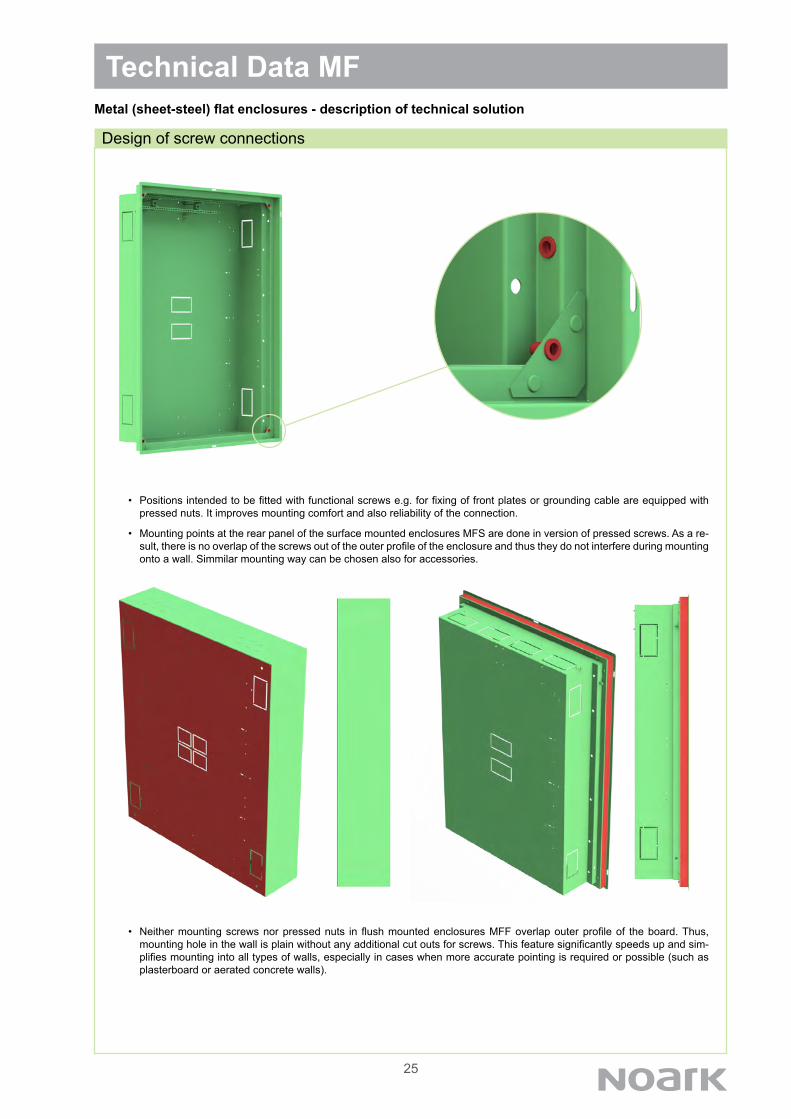
• Positions intended to be fitted with functional screws e.g. for fixing of front plates or grounding cable are equipped with pressed nuts. It improves mounting comfort and also reliability of the connection.
• Mounting points at the rear panel of the surface mounted enclosures MFS are done in version of pressed screws. As a re-sult, there is no overlap of the screws out of the outer profile of the enclosure and thus they do not interfere during mounting onto a wall. Simmilar mounting way can be chosen also for accessories.
• Neither mounting screws nor pressed nuts in flush mounted enclosures MFF overlap outer profile of the board. Thus, mounting hole in the wall is plain without any additional cut outs for screws. This feature significantly speeds up and sim-plifies mounting into all types of walls, especially in cases when more accurate pointing is required or possible (such as plasterboard or aerated concrete walls).
Technical Data MF
Design of screw connections
Metal (sheet-steel) flat enclosures - description of technical solution
26
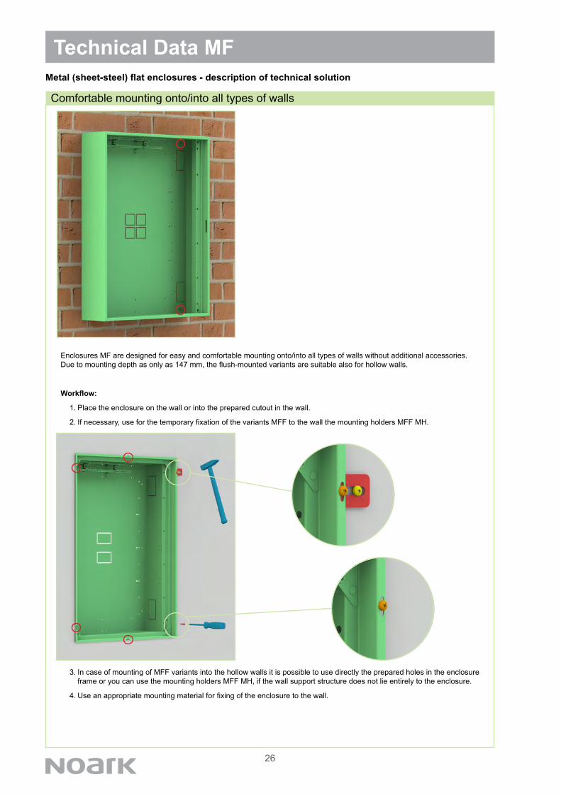
Enclosures MF are designed for easy and comfortable mounting onto/into all types of walls without additional accessories. Due to mounting depth as only as 147 mm, the flush-mounted variants are suitable also for hollow walls.
Workflow:
1. Place the enclosure on the wall or into the prepared cutout in the wall.
2. If necessary, use for the temporary fixation of the variants MFF to the wall the mounting holders MFF MH.
3. In case of mounting of MFF variants into the hollow walls it is possible to use directly the prepared holes in the enclosure frame or you can use the mounting holders MFF MH, if the wall support structure does not lie entirely to the enclosure.
4. Use an appropriate mounting material for fixing of the enclosure to the wall.
Technical Data MF
Comfortable mounting onto/into all types of walls
Metal (sheet-steel) flat enclosures - description of technical solution

27
Workflow:
1. Place the door frame to the enclosure and fix it in the corners with the attached screws. Do not tighten them.
2. Align the frame into the correct position. The design of enclosures allows slightly adjust the position of the frame in all three axis in case of unaccurate walling and depth correction.
3. Tighten the mounting screws in the corners.
Technical Data MFMetal (sheet-steel) flat enclosures - description of technical solution
Mounting and adjusting of the frame on MFF variants
28
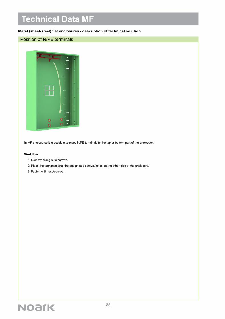
In MF enclosures it is possible to place N/PE terminals to the top or bottom part of the enclosure.
Workflow:
1. Remove fixing nuts/screws.
2. Place the terminals onto the designated screws/holes on the other side of the enclosure.
3. Fasten with nuts/screws.
Technical Data MFMetal (sheet-steel) flat enclosures - description of technical solution
Position of N/PE terminals

29
In the MF enclosures it is possible to reduce number of DIN rails on the mounting frame. It may be required e.g. when MCCBs or other devices on universal mounting plate are installed. Removing of DIN rail can be done by removing of rivet connection between the rail and the mounting frame or shortening of the entire mounting frame. The mounting frame itself does not prevent installation of mounting plates.
Mounting frame shortening workflow:
1. Mark the point where the frame should be shortened. It is necessary to take care that the frame is shortened behind the area where the mounting hole is located so that it can be fastened through it to the enclosure.
2. Loosen the retaining nuts/screws and remove the mounting frame from the enclosure.
3. Shorten the mounting frame where indicated. Shortening can be done by hacksaw or metal shears.
4. Place the shortened mounting frame back into the enclosure to its original position. Fasten it in newly formed end area with screws. In case of surface-mounted versions MFS it is possible to fasten it also from the back side with the countersunk screw with nut to avoid exceeding over the outer surface profile.
5. Fasten with the nuts/screws.
Technical Data MFMetal (sheet-steel) flat enclosures - description of technical solution
Removing of DIN rail and shortening of mounting frame
30
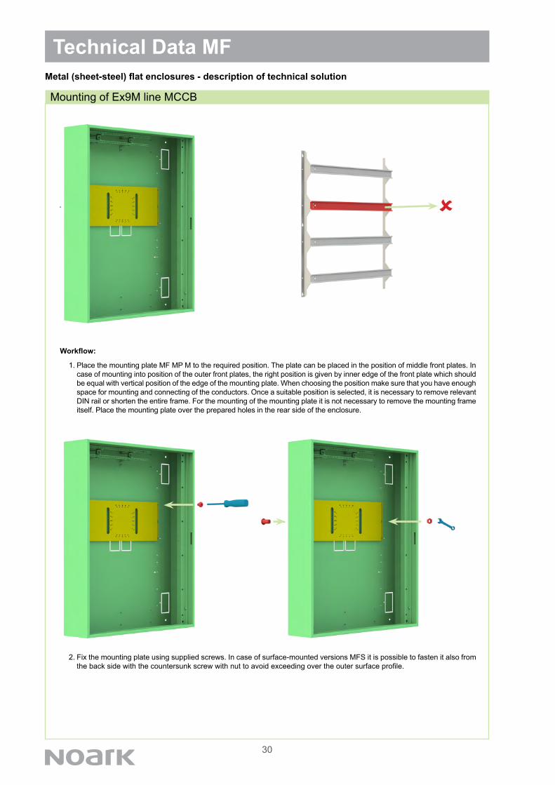
Workflow:
1. Place the mounting plate MF MP M to the required position. The plate can be placed in the position of middle front plates. In case of mounting into position of the outer front plates, the right position is given by inner edge of the front plate which should be equal with vertical position of the edge of the mounting plate. When choosing the position make sure that you have enough space for mounting and connecting of the conductors. Once a suitable position is selected, it is necessary to remove relevant DIN rail or shorten the entire frame. For the mounting of the mounting plate it is not necessary to remove the mounting frame itself. Place the mounting plate over the prepared holes in the rear side of the enclosure.
2. Fix the mounting plate using supplied screws. In case of surface-mounted versions MFS it is possible to fasten it also from the back side with the countersunk screw with nut to avoid exceeding over the outer surface profile.
Technical Data MF
Mounting of Ex9M line MCCB
Metal (sheet-steel) flat enclosures - description of technical solution

31
3. Place the circuit breaker over the appropriate mounting holes on the mounting plate according to the table. The holes are equipped with metric threads, MCCB is mounted using supplied screws. So it can be mounted when the mounting plate is installed in the enclosure. MCCBs of frame size M2 are installed directly. Front panel of the device is in the same level with the front plates. For MCCBs of frame size M1 there are two possibilities of mounting depth. Maximum mounting depth is reached by direct mounting onto the plate. If it is required to have front panel in the same level with front plates, the mounting pads WG 10 are mounted first to the plate, then the MCCB over them.
Technical Data MF
Mounting of Ex9M line MCCB
Metal (sheet-steel) flat enclosures - description of technical solution
Frame sizeand position of MCCB
Respective mounting holes
Frame sizeand position of MCCB
Respective mounting holes
Ex9M1 3P, vertical Ex9M2 3P, vertical
Ex9M1 4P, vertical Ex9M2 4P, vertical
Ex9M1 3P, horizontal Ex9M2 3P, horizontal
Ex9M1 4P, horizontal Ex9M2 4P, horizontal
+WG 10
Ex9M1
Ex9M2
32
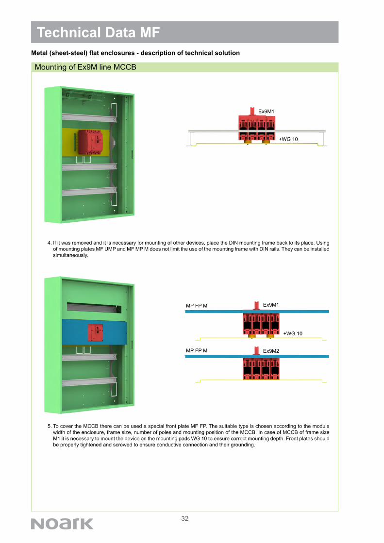
4. If it was removed and it is necessary for mounting of other devices, place the DIN mounting frame back to its place. Using of mounting plates MF UMP and MF MP M does not limit the use of the mounting frame with DIN rails. They can be installed simultaneously.
5. To cover the MCCB there can be used a special front plate MF FP. The suitable type is chosen according to the module width of the enclosure, frame size, number of poles and mounting position of the MCCB. In case of MCCB of frame size M1 it is necessary to mount the device on the mounting pads WG 10 to ensure correct mounting depth. Front plates should be properly tightened and screwed to ensure conductive connection and their grounding.
Technical Data MF
Mounting of Ex9M line MCCB
Metal (sheet-steel) flat enclosures - description of technical solution
+WG 10
MP FP M
MP FP M Ex9M1
Ex9M2
+WG 10
Ex9M1
33
Technical Data MFMetal (sheet-steel) flat enclosures - description of technical solution
Mounting of universal mounting plate
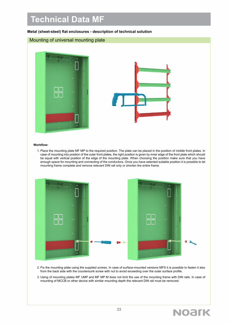
Workflow:
1. Place the mounting plate MF MP to the required position. The plate can be placed in the position of middle front plates. In case of mounting into position of the outer front plates, the right position is given by inner edge of the front plate which should be equal with vertical position of the edge of the mounting plate. When choosing the position make sure that you have enough space for mounting and connecting of the conductors. Once you have selected suitable position it is possible to let mounting frame complete and remove relevant DIN rail only or shorten the entire frame.
2. Fix the mounting plate using the supplied screws. In case of surface-mounted versions MFS it is possible to fasten it also from the back side with the countersunk screw with nut to avoid exceeding over the outer surface profile.
3. Using of mounting plates MF UMP and MF MP M does not limit the use of the mounting frame with DIN rails. In case of mounting of MCCB or other device with similar mounting depth the relevant DIN rail must be removed.
34
Technical Data MFMetal (sheet-steel) flat enclosures - description of technical solution
Cable fixing rail MF CFR
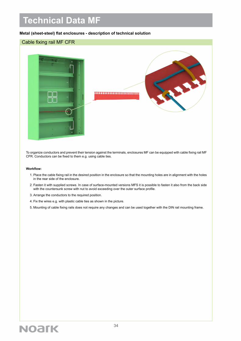
To organize conductors and prevent their tension against the terminals, enclosures MF can be equipped with cable fixing rail MF CFR. Conductors can be fixed to them e.g. using cable ties.
Workflow:
1. Place the cable fixing rail in the desired position in the enclosure so that the mounting holes are in alignment with the holes in the rear side of the enclosure.
2. Fasten it with supplied screws. In case of surface-mounted versions MFS it is possible to fasten it also from the back side with the countersunk screw with nut to avoid exceeding over the outer surface profile.
3. Arrange the conductors to the required position.
4. Fix the wires e.g. with plastic cable ties as shown in the picture.
5. Mounting of cable fixing rails does not require any changes and can be used together with the DIN rail mounting frame.
35
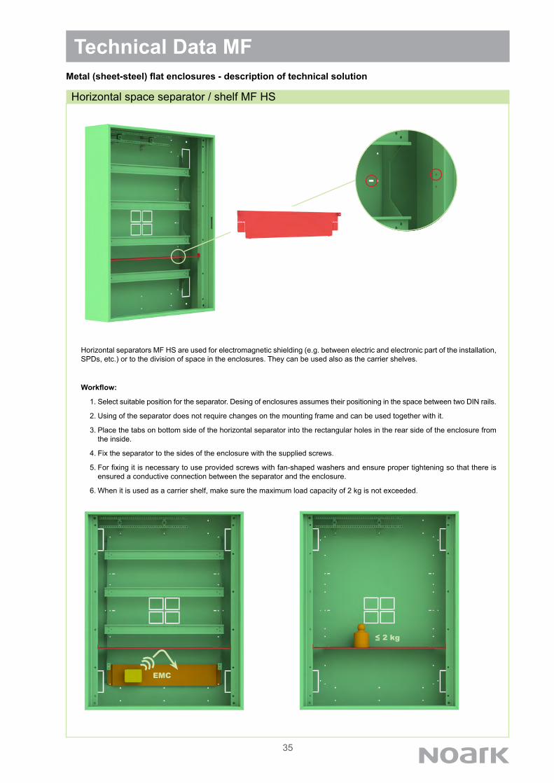
Horizontal separators MF HS are used for electromagnetic shielding (e.g. between electric and electronic part of the installation, SPDs, etc.) or to the division of space in the enclosures. They can be used also as the carrier shelves.
Workflow:
1. Select suitable position for the separator. Desing of enclosures assumes their positioning in the space between two DIN rails.
2. Using of the separator does not require changes on the mounting frame and can be used together with it.
3. Place the tabs on bottom side of the horizontal separator into the rectangular holes in the rear side of the enclosure from the inside.
4. Fix the separator to the sides of the enclosure with the supplied screws.
5. For fixing it is necessary to use provided screws with fan-shaped washers and ensure proper tightening so that there is ensured a conductive connection between the separator and the enclosure.
6. When it is used as a carrier shelf, make sure the maximum load capacity of 2 kg is not exceeded.
Technical Data MF
Horizontal space separator / shelf MF HS
Metal (sheet-steel) flat enclosures - description of technical solution
≤ 2 kg
EMC

36
The enclosures are supplied with front plates with device cutout 45 mm (two wide outer plates and the rest standard middle pla-tes). Number of front places is determined by the size of the enclosure, see. p. 20. If necessary, basic plates can be replaced by other versions. Possible variants are depicted in the picture below.
Outer front plates - variants
Standard middle front plates - variants
Technical Data MFMetal (sheet-steel) flat enclosures - description of technical solution
Variants of front plates
37
Technical Data MFMetal (sheet-steel) flat enclosures - description of technical solution
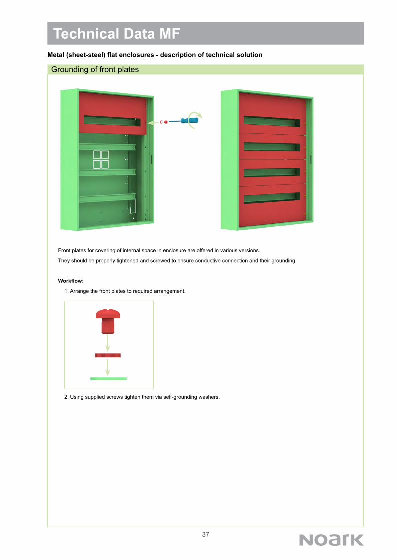
Front plates for covering of internal space in enclosure are offered in various versions.
They should be properly tightened and screwed to ensure conductive connection and their grounding.
Workflow:
1. Arrange the front plates to required arrangement.
2. Using supplied screws tighten them via self-grounding washers.
Grounding of front plates

38
The design and construction of the door and door frame in the MF enclosures reduces noise for example during vib-ration of the building.
• When closed, the door are fixed in their position not only by lock and hinges, but also with plastic pads preventing move-ments and direct impact into the door frame.
• Horizontal door edges are shortened to avoid contact with the frame all around its circumference. This is reflected espe-cially in cases where the enclosure is mounted into/onto uneven surface. This solution also optically reduces visibility of uneven mounting (twisting of door) caused by uneven wall.
Technical Data MF
Noiseless door construction
Metal (sheet-steel) flat enclosures - description of technical solution

39
Technical Data MF
Enclosures MF are characterized with high stiffness thanks to robust material used.
• They are less susceptible to damage during transport, installation and also during using.
• There is no deformation even at higher weight load by devices.
• There is no sag of the door, even when door are not fully closed. And it applies also if there are mounted e.g. panel moun-ted devices.
Metal (sheet-steel) flat enclosures - description of technical solution
Rigid and robust construction
40
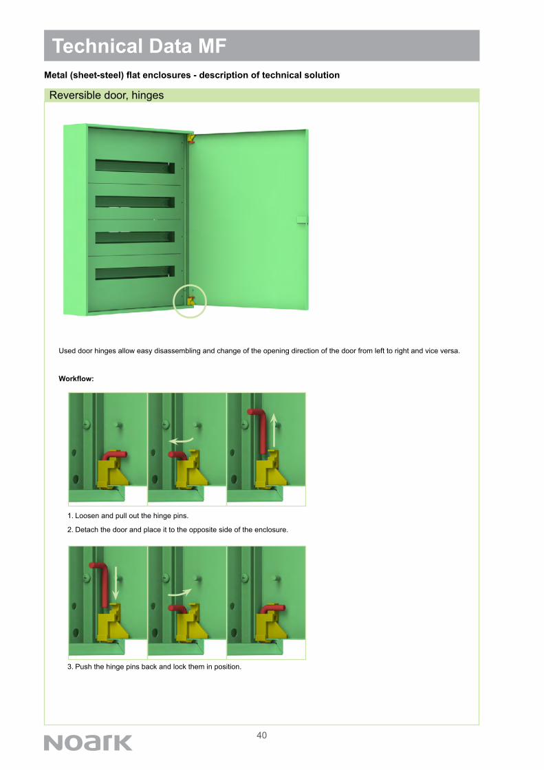
Used door hinges allow easy disassembling and change of the opening direction of the door from left to right and vice versa.
Workflow:
1. Loosen and pull out the hinge pins.
2. Detach the door and place it to the opposite side of the enclosure.
3. Push the hinge pins back and lock them in position.
Technical Data MF
Reversible door, hinges
Metal (sheet-steel) flat enclosures - description of technical solution
41
Technical Data MFMetal (sheet-steel) flat enclosures - description of technical solution
Lock-key mounting
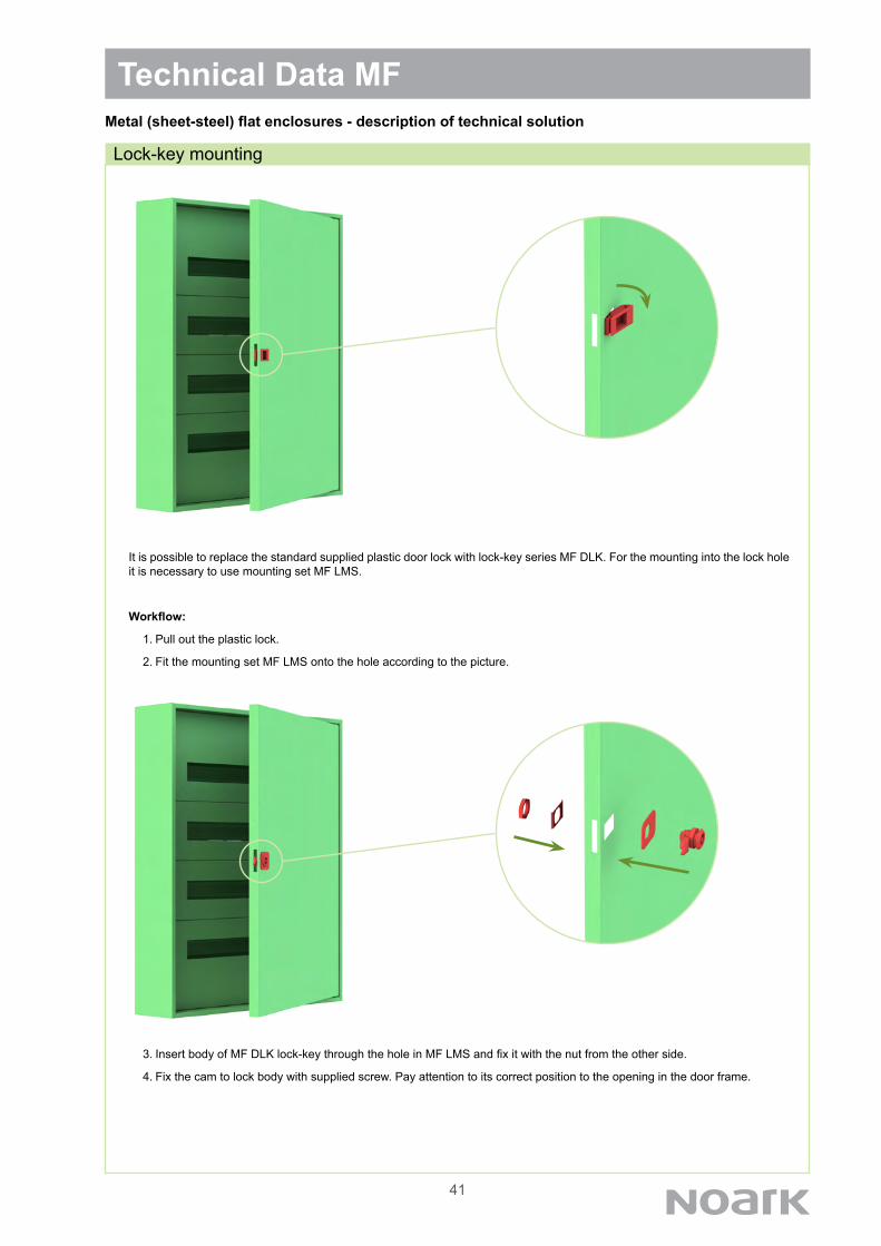
It is possible to replace the standard supplied plastic door lock with lock-key series MF DLK. For the mounting into the lock hole it is necessary to use mounting set MF LMS.
Workflow:
1. Pull out the plastic lock.
2. Fit the mounting set MF LMS onto the hole according to the picture.
3. Insert body of MF DLK lock-key through the hole in MF LMS and fix it with the nut from the other side.
4. Fix the cam to lock body with supplied screw. Pay attention to its correct position to the opening in the door frame.
42
Technical Data MFMetal (sheet-steel) flat enclosures - description of technical solution
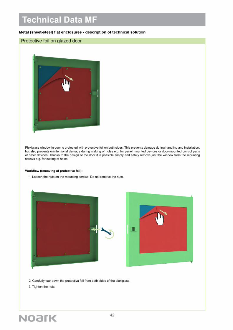
Protective foil on glazed door
Plexiglass window in door is protected with protective foil on both sides. This prevents damage during handling and installation, but also prevents unintentional damage during making of holes e.g. for panel mounted devices or door-mounted control parts of other devices. Thanks to the design of the door it is possible simply and safely remove just the window from the mounting screws e.g. for cutting of holes.
Workflow (removing of protective foil):
1. Loosen the nuts on the mounting screws. Do not remove the nuts.
2. Carefully tear down the protective foil from both sides of the plexiglass.
3. Tighten the nuts.
43
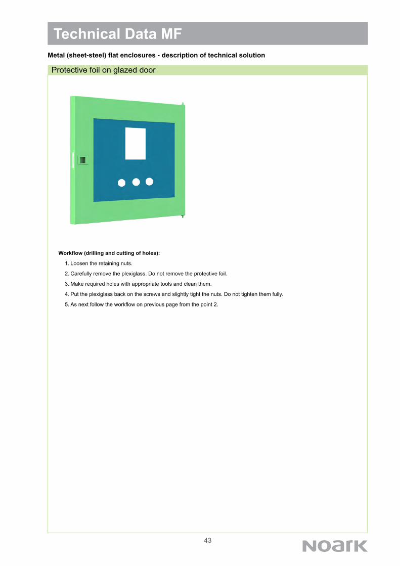
Workflow (drilling and cutting of holes):
1. Loosen the retaining nuts.
2. Carefully remove the plexiglass. Do not remove the protective foil.
3. Make required holes with appropriate tools and clean them.
4. Put the plexiglass back on the screws and slightly tight the nuts. Do not tighten them fully.
5. As next follow the workflow on previous page from the point 2.
Technical Data MFMetal (sheet-steel) flat enclosures - description of technical solution
Protective foil on glazed door