Embed Size (px)
Citation preview
8/8/2019 MET 49-1-3 7 Solenicki
http://slidepdf.com/reader/full/met-49-1-3-7-solenicki 1/6
G. SOLENI^KI, I. BUDI], D. CIGLAR
DETERMINATION OF THERMALCONDUCTIVITY IN FOUNDRY MOULD MIXTURES
Received – Prispjelo: 2008-10-24Accepted – Prihva}eno: 2009-03-15
Original Scientific Paper – Izvorni znanstveni rad
INTRODUCTION
For a thorough understanding of the behaviour of foundry mould mixtures, a good knowledge of thermal
properties of mould materials [1-3] is required. Thermalconductivity is an important parameter among them. Inorder to determine the thermal conductivity of realfoundry mould mixtures, an instrument for measuringthermal conductivity has been designed [4, 5].
Laboratory determination of thermal conductivity of mould mixtures enables a better control over scabbingdefects which are a major problem in green sand mouldmixtures [6]. The layer which is responsible for their formation is a part of the mould which has been heatedto the temperature higher than the temperature of quartzsand allotropic modification, i.e. the temperature above570 oC. Such layer is very unstable and is the main causeof internal stresses. As the structure moves and high in-
ternal stresses occur, the mixture is being deformed andsmall parts of the mould mixture break off and fall intothe melt, thus causing mould defects.
INSTRUMENT FOR THE DETERMINATIONOF THERMAL CONDUCTIVITY
Since the foundry mould mixture consists of the basematerial (sand), a bond (bentonite), water and mixture
additives, the most reliable way of determining thermal properties of the mixture is to do it experimentally. Ex- perimental determination of thermal properties of
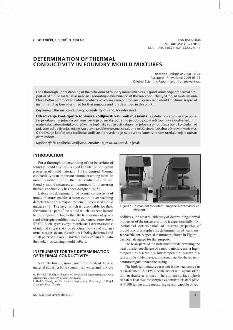
mould mixtures implies the determination of heat trans-fer coefficient. A special instrument, shown in Figure 1,has been designed for that purpose.
The basic parts of the instrument for determining theheat transfer coefficient of a mould mixture are: a high-temperature reservoir, a low-temperature reservoir, atest sample holder device, a microcontroller-based tem-
perature regulator and the casing.The high-temperature reservoir is the heat source in
the instrument. A 2 kW electric heater with a plate of 90mm in diameter is used. The contact surface whichtransfers heat to a test sample is a 6 mm thick steel plate.A Pt100 temperature measuring sensor capable of rec-
METALURGIJA 49 (2010) 1, 3-7 3
For a thorough understanding of the behaviour of foundry mould mixtures, a good knowledge of thermal pro-
perties of mould materials is needed.Laboratory determination of thermal conductivity of mould mixtures ena-
bles a better control over scabbing defects which are a major problem in green sand mould mixtures. A special
instrument has been designed for that purpose and it is described in this work.
Key words: thermal conductivity, granularity of sand, foundry sand
Odre|ivanje koeficijenta toplinske vodljivosti kalupnih mje{avina. Za detaljno razumijevanje pona-{anja kalupnih mje{avina prilikom lijevanja odljevaka potrebno je dobro poznavati toplinska svojstva kalupnih
materijala. Laboratorijsko odre|ivanje toplinske vodljivosti kalupnih mje{avina omogu}ava bolju kontrolu nad
pojavom odlupljivanja, koja je kao glavni problem vezana za kalupne mje{avine s fizikalno o~vrstivim vezivima.
Odre|ivanje koeficijenta toplinske vodljivosti provedeno je na posebno konstruiranom ure|aju koji je opisan
ovim radom.
Klju~ne rije~i: toplinska vodljivost, zrnatost pijeska, kaluparski pijesak
ISSN 0543-5846
METABK 49(1) 3-7 (2010)UDC – UDK 536.21: 621.742.42=111
G. Soleni~ki, D. Ciglar, Faculty of Mechanical Engineering and NavalArchitecture University of Zagreb, CroatiaI. Budi}, Faculty of Mechanical Engineering University of Osijek,Slavonski Brod, Croatia
Figure 1. Instrument for determining the heat transfer co-efficient
8/8/2019 MET 49-1-3 7 Solenicki
http://slidepdf.com/reader/full/met-49-1-3-7-solenicki 2/6
ognizing temperatures from -200 oC to +530 oC is at-tached to the steel plate. The measuring sensor is di-rectly connected to the microcontroller-based tempera-ture regulator which uses the measured value for main-
taining the constant temperature of the high-temperaturereservoir plate.
The low-temperature reservoirmadeof aluminiumisused to carry away heat from the test sample. On thelower part of the reservoir there are ducts. A constant in-
put temperature of thewater flowing through these ductsensures a constant temperature of the low-temperaturereservoir which takes over the heat flow transferredfrom the high-temperature reservoir through the sample.The heat quantity transferred to water through the sam-
ple in a unit of time, can be calculated from the water flow and the difference between the temperatures at theinlet and outlet of the low-temperature reservoir.
The high-temperature reservoir is fixed to the casing
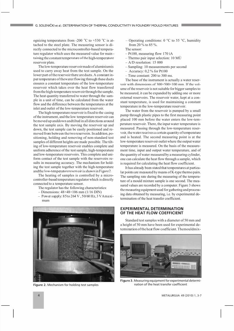
of the instrument, and the low temperature reservoir can be moved up anddown andtilted in all directions aroundthe test sample axis. By moving the reservoir up anddown, the test sample can be easily positioned and re-moved from between the two reservoirs. In addition, po-sitioning, holding and removing of non-standard testsamples of different heights are made possible. The tilt-ing of low-temperature reservoir enables complete anduniform adherence of the test sample, high-temperatureand low-temperature reservoirs. This complete and uni-form contact of the test sample with the reservoirs re-sults in measuring accuracy. The mechanism for hold-ing the test sample together with the high-temperatureandthe low-temperaturereservoir is shown in Figure2.
The heating of samples is controlled by a micro-controller-based temperature regulator which is directlyconnected to a temperature sensor.
The regulator has the following characteristics: – Dimensions: 48×48×106 mm (1/16 DIN) – Power supply: 85to 264 V , 50/60 Hz, 3 VAmaxi-
mum
– Operating conditions: 0 °C to 55 °C, humidityfrom 20 % to 85 %.
The sensor: – Pt100, measuring flow 170 ìA
– Thermo pair input selection: 10 MÙ – A/D resolution: 15 000 – Sampling: 10 measurements per second – Accuracy: 0,2 % for Pt100 – Time constant: 200 to 300 ms.The base of the instrument is actually a water reser-
voir with dimensions of 300×500×100 mm. If the vol-ume of the reservoir is not suitable for bigger samples to
be measured, it can be expanded by adding one or moreexternal reservoirs. The reservoir water, kept at a con-stant temperature, is used for maintaining a constanttemperature in the low-temperature reservoir.
The water from the reservoir is pumped by a small
pump through plastic pipes to the first measuring point placed 100 mm before the water enters the low-tem- perature reservoir. There, the input water temperature ismeasured. Passing through the low-temperature reser-voir, the water receives a certain quantity of temperatureand is heated. The second measuring point is at thelow-temperature reservoir outlet where the output water temperature is measured. On the basis of the measure-ment time, input and output water temperature, and of the quantity of water measured by a measuring cylinder,one can calculate the heat flow through a sample, whichis required for calculating the heat flow coefficient.
It has already been stated that temperatures at particu-
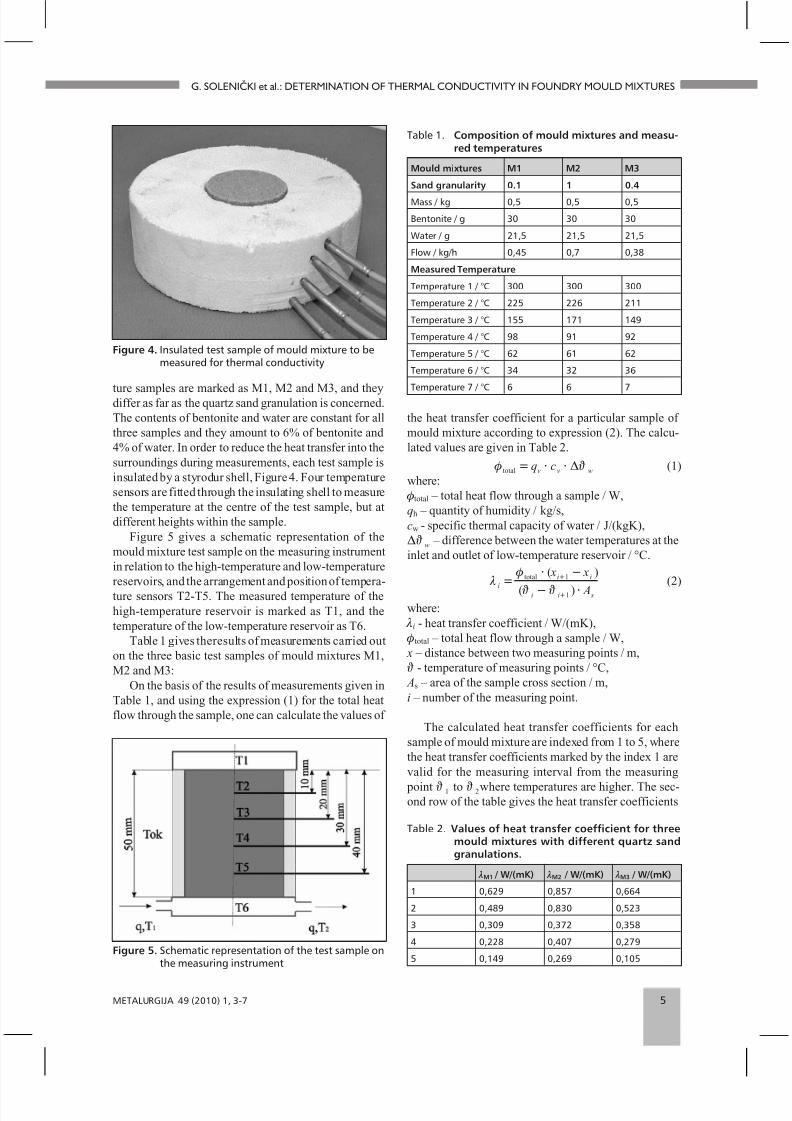
lar points are measured by means of K-type thermo pairs.The sampling rate during the measuring of the tempera-ture of a mould mixture sample is one second. The mea-sured values are recorded by a computer. Figure 3 showsthe measuring equipment used for gathering and process-ing data obtained by measuring, i.e. by experimental de-termination of the heat transfer coefficient.
EXPERIMENTAL DETERMINATIONOF THE HEAT FLOW COEFFICIENT
Standard test samples with a diameter of 50 mm anda height of 50 mm have been used for experimental de-termination of the heat flow coefficient. Themouldmix-
4 METALURGIJA 49 (2010) 1, 3-7
G. SOLENI^KI et al.: DETERMINATION OF THERMAL CONDUCTIVITY IN FOUNDRY MOULD MIXTURES
Figure 2. Mechanism for holding test samples
Figure 3. Measuring equipment for experimental determi-nation of the heat transfer coefficient
8/8/2019 MET 49-1-3 7 Solenicki
http://slidepdf.com/reader/full/met-49-1-3-7-solenicki 3/6
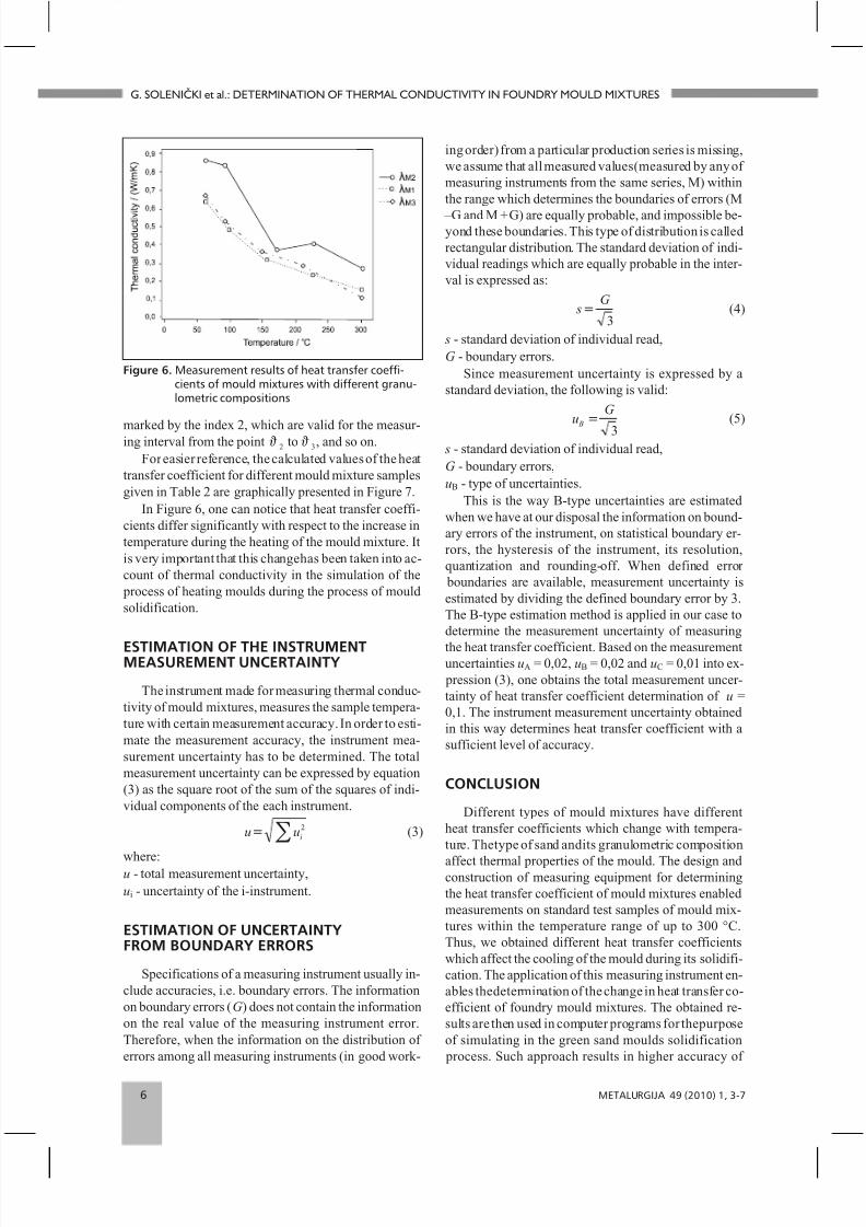
ture samples are marked as M1, M2 and M3, and theydiffer as far as the quartz sand granulation is concerned.The contents of bentonite and water are constant for allthree samples and they amount to 6% of bentonite and4% of water. In order to reduce the heat transfer into thesurroundings during measurements, each test sample isinsulated by a styrodur shell, Figure 4. Four temperaturesensors are fitted through the insulating shell to measurethe temperature at the centre of the test sample, but atdifferent heights within the sample.
Figure 5 gives a schematic representation of themould mixture test sample on the measuring instrumentin relation to the high-temperature and low-temperaturereservoirs, and the arrangement and position of tempera-ture sensors T2-T5. The measured temperature of thehigh-temperature reservoir is marked as T1, and thetemperature of the low-temperature reservoir as T6.
Table 1 gives theresults of measurements carried outon the three basic test samples of mould mixtures M1,M2 and M3:
On the basis of the results of measurements given inTable 1, and using the expression (1) for the total heatflow through the sample, one can calculate the values of
the heat transfer coefficient for a particular sample of mould mixture according to expression (2). The calcu-lated values are given in Table 2.
f J total = × ×q cv v wD (1)where:
ftotal – total heat flow through a sample / W,qh – quantity of humidity / kg/s,cw - specific thermal capacity of water / J/(kgK),DJ w – difference between the water temperatures at theinlet and outlet of low-temperature reservoir / °C.
l f
J J i
i i
i i s
x x
A=
× -
- ×
+
+
total ( )
( )
1
1
(2)
where: li - heat transfer coefficient / W/(mK), ftotal – total heat flow through a sample / W, x – distance between two measuring points / m, J - temperature of measuring points / °C, As – area of the sample cross section / m,i – number of the measuring point.
The calculated heat transfer coefficients for eachsample of mould mixture are indexed from 1 to 5, wherethe heat transfer coefficients marked by the index 1 arevalid for the measuring interval from the measuring
point J 1 to J 2where temperatures are higher. The sec-ond row of the table gives the heat transfer coefficients
METALURGIJA 49 (2010) 1, 3-7 5
G. SOLENI^KI et al.: DETERMINATION OF THERMAL CONDUCTIVITY IN FOUNDRY MOULD MIXTURES
Figure 4. Insulated test sample of mould mixture to bemeasured for thermal conductivity
Figure 5. Schematic representation of the test sample onthe measuring instrument
Table 1. Composition of mould mixtures and measu-red temperatures
Mould mixtures M1 M2 M3
Sand granularity 0.1 1 0.4
Mass / kg 0,5 0,5 0,5
Bentonite / g 30 30 30
Water / g 21,5 21,5 21,5
Flow / kg/h 0,45 0,7 0,38
Measured Temperature
Temperature 1 / °C 300 300 300
Temperature 2 / °C 225 226 211
Temperature 3 / °C 155 171 149
Temperature 4 / °C 98 91 92
Temperature 5 / °C 62 61 62
Temperature 6 / °C 34 32 36
Temperature 7 / °C 6 6 7
Table 2. Values of heat transfer coefficient for threemould mixtures with different quartz sandgranulations.
lM1 / W/(mK) lM2 / W/(mK) lM3 / W/(mK)
1 0,629 0,857 0,664
2 0,489 0,830 0,523
3 0,309 0,372 0,358
4 0,228 0,407 0,279
5 0,149 0,269 0,105
8/8/2019 MET 49-1-3 7 Solenicki
http://slidepdf.com/reader/full/met-49-1-3-7-solenicki 4/6
marked by the index 2, which are valid for the measur-ing interval from the point J 2 to J 3, and so on.For easier reference, the calculated values of the heat
transfer coefficient for different mould mixture samplesgiven in Table 2 are graphically presented in Figure 7.
In Figure 6, one can notice that heat transfer coeffi-cients differ significantly with respect to the increase intemperature during the heating of the mould mixture. Itis very important that this changehas been taken into ac-count of thermal conductivity in the simulation of the
process of heating moulds during the process of mouldsolidification.
ESTIMATION OF THE INSTRUMENTMEASUREMENT UNCERTAINTY
The instrument made for measuring thermal conduc-tivity of mould mixtures, measures the sample tempera-ture with certain measurement accuracy. In order to esti-mate the measurement accuracy, the instrument mea-surement uncertainty has to be determined. The totalmeasurement uncertainty can be expressed by equation(3) as the square root of the sum of the squares of indi-vidual components of the each instrument.
u ui= å 2 (3)
where:u - total measurement uncertainty,ui - uncertainty of the i-instrument.
ESTIMATION OF UNCERTAINTYFROM BOUNDARY ERRORS
Specifications of a measuring instrument usually in-clude accuracies, i.e. boundary errors. The informationon boundary errors (G ) does not contain the informationon the real value of the measuring instrument error.Therefore, when the information on the distribution of errors among all measuring instruments (in good work-
ing order) from a particular production series is missing,we assume that all measured values(measured by any of measuring instruments from the same series, M) withinthe range which determines the boundaries of errors (M
–G and M +G) are equally probable, and impossible be-yond these boundaries. This type of distribution is calledrectangular distribution. The standard deviation of indi-vidual readings which are equally probable in the inter-val is expressed as:
sG
=3
(4)
s - standard deviation of individual read,G - boundary errors.
Since measurement uncertainty is expressed by astandard deviation, the following is valid:
uG
B =
3
(5)
s - standard deviation of individual read,G - boundary errors,uB - type of uncertainties.
This is the way B-type uncertainties are estimatedwhen we have at our disposal the information on bound-ary errors of the instrument, on statistical boundary er-rors, the hysteresis of the instrument, its resolution,quantization and rounding-off. When defined error
boundaries are available, measurement uncertainty isestimated by dividing the defined boundary error by 3.The B-type estimation method is applied in our case todetermine the measurement uncertainty of measuring
the heat transfer coefficient. Based on the measurementuncertainties uA = 0,02, uB = 0,02 and uC = 0,01 into ex-
pression (3), one obtains the total measurement uncer-tainty of heat transfer coefficient determination of u =0,1. The instrument measurement uncertainty obtainedin this way determines heat transfer coefficient with asufficient level of accuracy.
CONCLUSION
Different types of mould mixtures have differentheat transfer coefficients which change with tempera-ture. Thetype of sand andits granulometric composition
affect thermal properties of the mould. The design andconstruction of measuring equipment for determiningthe heat transfer coefficient of mould mixtures enabledmeasurements on standard test samples of mould mix-tures within the temperature range of up to 300 °C.Thus, we obtained different heat transfer coefficientswhich affect the cooling of the mould during its solidifi-cation. The application of this measuring instrument en-ables thedetermination of the change in heat transfer co-efficient of foundry mould mixtures. The obtained re-sults are then used in computer programs for thepurposeof simulating in the green sand moulds solidification
process. Such approach results in higher accuracy of
6 METALURGIJA 49 (2010) 1, 3-7
G. SOLENI^KI et al.: DETERMINATION OF THERMAL CONDUCTIVITY IN FOUNDRY MOULD MIXTURES
Figure 6. Measurement results of heat transfer coeffi-cients of mould mixtures with different granu-lometric compositions

8/8/2019 MET 49-1-3 7 Solenicki
http://slidepdf.com/reader/full/met-49-1-3-7-solenicki 5/6
simulation results intended to determine the rate atwhich moulds are heated. Knowing the real heatingrates of moulds, one can estimate more precisely the
probability of defect occurrence in them, and increase
the quality of obtained moulds.
REFERENCES
[1] I. Katavi}, Ljevarstvo, Sveu~ili{te u Rijeci, 1993.[2] Z. Bona~i} Mandini}, I. Budi}, Ljevarstvo zemalja u tranzi-
ciji – hrvatske perspektive, Strojarstvo, 37 (1995), 143-147.[3] C. Bates, O. Diran, Metalcasting Industry Technology Ro-
admap, American Foundry Society, 10 (2003) 3, 12 - 13.
[4] G. Soleni~ki, Istra ivanje mehanizma nastanka odlupljivan- ja u kalupu, doktorski rad, Fakultet strojarstva i brodograd-nje, Zagreb, 2007.
[5] K. Kubo, K. Mizuuchi, Measurement of Thermal Propertiesof Sand Molds by Pouring Method, International Foundry,
50 (1983) 5, 1-21.[6] J. Bataille, Thermodynamics of mixtures, Thermodyna-
mics, 2 (1977) 1, 49 – 65.
Note: The responsible translator for English language is B.Toki}, Zagreb,Croatia.
METALURGIJA 49 (2010) 1, 3-7 7
G. SOLENI^KI et al.: DETERMINATION OF THERMAL CONDUCTIVITY IN FOUNDRY MOULD MIXTURES
8/8/2019 MET 49-1-3 7 Solenicki
http://slidepdf.com/reader/full/met-49-1-3-7-solenicki 6/6
REGISTRATION FORM SHMD ’2010
June 20 - 24, 2010
Registration Form (see web site) should be sent not later than 31th January 2010, (after paid the Participation Fee)to:
Croatian Metallurgical Society,Berislavi}eva 6, 10000 Zagreb, Croatia,or fax: + 385 1 619 86 89
Name: ....................................................................................................
Titleand Profession: .......................................................................
University or Company: ................................................................
Mailing Address: ..............................................................................
Zip Code: .............................................................................................
City: .......................................................................................................
Country: ...............................................................................................
Phone: ...................................................................................................
Fax: .........................................................................................................
E-mail: ..................................................................................................
Attendance: with a paper [ ] ; without a paper [ ],
Title of the paper: .............................................................................
....................................................................................................................
....................................................................................................................
....................................................................................................................
Author(s): ............................................................................................
....................................................................................................................
Date: .......................................................................................................
Signature: ............................................................................................
ACCOMODATION
Solaris Holiday Resort, [ibenik, Croatia
HOTEL ACCOMODATION FORM SHMD’2010 (SEE WEB SITE)
Deadline of reservation: 20th May 2010 to:Phone: + 385 22 361 013, fax: + 385 22 361 800Solaris Holiday Resort, 22 000 [ibenik, Croatia
Name: ....................................................................................................
Phone: ...................................................................................................
Address: ...............................................................................................
Arrival Date: .........................06.2010;Time: ..........................
Departure date: .....................06.2010;Time: .......................
Please indicate type of room required:(price are per person/day)
double 1/2 single 1/1room + breakfast 47.50 € [ ] 68.50 € [ ]
half board 52.50 € [ ] 73.50 € [ ]
full board 64.50 € [ ] 85.50 € [ ]
visitor’s tax - person/day 0.8 €
The prices validly: June 18 - 27, 2010 (å 9 days).
Date: .......................................................................................................
Signature: .............................................................................................
Information: Solaris Holiday Resort
Phone: + 385 22 361 004361 005
Fax: + 385 22 361 800
The more details about the town [ibenik and SolarisHoliday Resort, please see: www.solaris.hr
8 METALURGIJA 49 (2010) 1, 8
9th
INTERNATIONAL SYMPOSIUM OF CROATIAN METALLURGICALSOCIETY “MATERIALS AND METALLURGY”, SHMD’ 2010