Embed Size (px)
Citation preview
Meridian I
ENGINEERINGHANDBOOKUpdate Package
PO71 3374Prepared by:
Meridian 1 Product MarketingSanta Clara, CA
Issue: April 1990-0
FOR INTERNAL USE ONLYIlit
llortllcrntclcculll
Meridian 1
Engineering Handbook
Table Of Contents
Chapter Description Page
1 ................................................rn- ................................................. l-l
2 ...............................................SysbmGti ..........................................2-l
3 ................................................pluchxF!sJa .........................................3-l
4 ................................................systan- .......................................4 1
5 ................................................pIcxhlam .......................................51
6 ...............................................hflZdklMsavices.. .................................61
7................................................QSlElllW~ ....................................7-l
8 ................................................OrQringInf~ .....................................8 - l
9 ................................................T Giffk. ........................................................9-l
10..............................................TkrhnkalSw .................................. lo-1
1 1 ..............................................ListofTm.. ............................................ll- 1
l-l
Chapter II : Introduction
hAeridian 1Meridian 1 Communication Systems are a family of digital multiplex voice and dataswitching systems, built upon a foundation of state-of-the art digital switchingequipment and advanced software program control. Meridian 1 CommunicationSystems have a range of System Options available, providing sophisticated voiceand data services for PBX and private CO applications for up to 60,000 users.
The Meridian 1 is the single source solution to the complexities of today’s businessenvironment and represents the merger of the functionality of existing Meridian SL-1, Meridian SL-100, and Meridian SuperNode systems into a single, modularcommunications product portfolio. It offers various system options that are tailoredto meet the application requirements of small, medium, and large sized businessorganizations.
The Purpose of this handbook is two-fold:
1 . To focus on capabilities and services that have evolved from theMeridian SL-1 architecture (Meridian 1 System Options 21,21A,51,61, and 71).
2. To provide a consolidated source of selective reference material toassist sales engineers and product support personnel in their everydaywork tasks.
-The Engineering Handbook is NOT a replacement for existing documentation such as NorthernTelecom Practices (NT%) and feature Documents, which have their own specific use. Instead it isstructured specifically to address the business applications of the Meridian 1. Modular organization ofthe Engineering Handbook has been selected for ease of use.
Engineering Handbook
l-2 System Architecture
Chapter 1: INTRODUCTIONdiscusses the purpose and organization of the handbook
Chapter 2: SYSTEM OVERVIEWprovides a general overview of the foundation upon which Meridian 1 SL-1 is built
Chapter 3: PRODUCT EVOLUTIONchronicles the timetable of events that have evolved for over a decade to theintroduction of Meridian 1
Chapter 4: SYSTEM ARCHITECTUREdetails the various elements that make up the system architecture
Chapter 5: PRODUCT DESCRIPTIONdescribes the capabilities ofthe Meridian 1 System Options 2 1,2 1 A, 5 1,6 1 , and 7 1and various members of the Meridian product family
Chapter 6: MERIDIAN DATA SERVICESoutlines the data products and services that are currently available on Meridian 1
Chapter 7: SYSTEM CONFIGURATIONprovides configuration and compatibility parameters for both hardware andsoftware, along with capacity guidelines
Chapter 8: ORDERING INFORMATIONdetails ordering and packaging information of Meridian 1 SL-1
Chapter 9: TRAFFICdiscusses various aspects of traffic engineering for consideration in systemconfiguration
Chapter 10: TECHNICAL SPECIFICATIONSconsolidates the technical specifications that support Meridian 1 SL-1
Chapter 11: LIST OF TERMSprovides a glossary of terms widely used in the digital communications environment- -
The Meridian 1 Engineering Handbook was developed to provide useful and usable information. Yoursuggestions are solicited so that the most effective use can be derived from this handbook. Please directall correspondence to:
Northern Telecom Inc.2305 Mission College Blvd.
Santa Clara, CA 95054-1591Attn: Meridian 1 Engineering Handbook
U . .
Engineering Handbook
2-1
Chapter 2: System overview .ContentsModular packagingSystem enhancementsSystem organization
Common EquipmentNetworkPeripheral Equipment
System optionsSystem option 21System option 51System option 61System option 71
Features and servicesMeridian softwareDesktop products
Meridian 1 SL-1 digital setMeridian attendant console
System administrationMeridian 1 data servicesMeridian networking solutions
Meridian Networked ACDMeridian MailMeridian LANSTAR
2-22-32-42-42-42-42-62-62-62-62-62-72-72-82-82-92 - 9
2-102-102 - 1 12-l 12-12
Meridian 1 Communication Systems consolidate the functionality of the MeridianSL-1, Meridian SL-100, and Meridian SuperNode PBX portfolios into a singleproduct line. - -The design approach to the Meridian 1 architecture, combined with modularcomponents, has produced extremely flexible system options that are adaptable tomany applications in the business environment.
The Meridian 1 system options 2 1,s 1,6 1, and 7 1, based on the Meridian SL- 1architecture, provide advanced voice features, data connectivity and local areanetwork communications, and sophisticated information services for PBXapplications ranging in size from 30 to 10,000 users,
Engineering Handbook
2-2 System Overview
The foundation for each Meridian 1 SL-1 system option is a voice and data circuit-switched digital sub-system under software control. It is comprised of a CentralProcessing Unit (CPU), memory store, and a digital switching network that usestime division multiplexing and pulse code modulation techniques. Peripheralinterfaces are used to connect a wide array of telephones, trunks, and terminals.
Modular packagingSystem hardware provisioning is based upon a highly modular packaging schemethat uses an advanced aluminum die-casting process. The basic unit of packaging iscalled the Universal Equipment Module, or UEM. Each module contains allhardware required (such as backplane, card cage, power supply, cabling) to supporta specific system function, such as CPU, Network, or Peripheral Equipment (PE).The UEM has removeable front and rear covers with locking latches for easy accessto its contents. In addition, the UEM is designed to provide universal support for awide variety of card cages and structures to allow the integration of specialapplications and features, such as Meridian Mail, into the system. The UniversalEquipment Modules are both mechanically superior and aesthetically attractive, andprovide an advanced packaging platform for the future.
The UEMs are stacked one on top of another to form a column. Each column maycontain up to four UEMs. An expansion kit is provided to interconnect the columnsin a multi-column system to ensure compliance to FCC EMI/RFI regulations. Atthe base of each column of UEMs is the pedestal. The pedestal houses cooling fans,air filters, a power distribution assembly (including the circuit breakers and powerswitches) and a System Monitor circuit. At the top of each column is a top capassembly which consists of two air exhaust grills and a thermal sensor assembly.
System expansion simply requires adding one or more UEMs. The modularpackaging scheme also provides for low cost, easy expansion from one system typeto another. For example, the card cage assembly of a UEM containing commonequipment for a small system may be removed and replaced with the card cageassembly designed for larger systems. In addition, Peripheral Equipment, which isthe bulk of the system investment, is common to all systems and may be retainedwhen expanding from one system option to another.
The power distribution arrangement follows the modular design concept of theUEM packaging. Each module is truly universal in terms of power and cooling, andcontains its own multi-output power converter to supply all necessary voltages. Thesystem is designed so that there are no restrictions as a result of power or thermalconstraints. Any circuit card can go in any slot, and all modules can be filled tocapacity with any (logically) valid combination of cards, with virtually noengineering requirements. Both AC-powered and traditional DC-powered systemoptions are available, providing flexibility to meet a wide variety of customer needs.Part of the power architecture includes a System Monitor designed to provideenhanced power, cooling, and general system monitoring capabilities. The SystemMonitor interfaces to the CPU through a Serial Data Interface (SDI), for intelligenterror and status reporting.
Engineering Handbook
System Overview 2-3
System enhancementsThe comprehensive open architecture ensures continual growth in capacity andcapability to address ongoing demands imposed by business communication andinformation management needs. Building on the strength of the original SL-1architecture, this approach has enabled a smooth evolution to occur that takes fulladvantage of new technology as it becomes available, allowing customers to protecttheir installed investment while at the same time benefiting from these newtechnologies and features.
The development of Meridian 1 introduces major enhancements to the network andperipheral areas of the system. The implementation of microprocessor technologyto the peripheral circuit cards and their associated support interfaces creates a newset of Intelligent Peripheral Equipment. The on-board microprocessors off-loadprocessing functions previously performed by the CPU, resulting in an increase insystem real time capacity. In addition, they provide increased system diagnosticcapabilities for an improvement in maintainability. Where possible, hardwareswitch selection is replaced with software-controlled selection of circuit cardoptions. The on-board microprocessors also allow for circuit card parameters to bechanged without requiring hardware revisions. Parameters are stored on the systemdisk drive unit, and are downloaded to the circuit card at system reload or upon usercommand. The new cards also make use of on-board intelligence by reporting theirproduct code, serial number, release number, and manufacture location, assistingmaintenance and inventory control.
The Intelligent Peripheral Equipment (IPE) provides an increase in density onassociated peripheral circuit cards. For example, the digital line card provides 16voice and 16 data ports , for a total of 32 ports, and the analog line card provides 16ports. Since the IPE Module holds 16 cards, the maximum number of peripheralports (or terminal numbers) per module is 5 12. The overall impact is a 300 percentincrease in peripheral density.
Network capacity is enhanced through the introduction of the Superloop Networkcard, which interfaces to four regular network loops to extend 120 timeslots persuperloop to the IPE. This increased bandwidth and larger pool of timeslotsimproves the network traffic capacity by 25 percent for each 120 timeslot bundle.For high traffic or non-blocking applications, up to four superloops may beassigned to each IPE Module. Alternatively, since the PE address range has beenincreased such that up to 1024 TNs may be assigned to each superloop, low trafficapplications may have one superloop serving up to two IPE Modules.
Other enhancements include a migration to the DS-30 signaling method used byother Northern Telecom switching products, providing a commonality of signalingschemes throughout the Meridian 1 Communication Systems family so that growthbeyond 10,000 ports is possible without a change in PE type. Together, the newsignaling scheme, the additional processing capabilities, and the increasedaddressing and termination capacity, provide a ready platform for the integration ofISDN Basic Rate Access (BRA).
2-4 System Overview
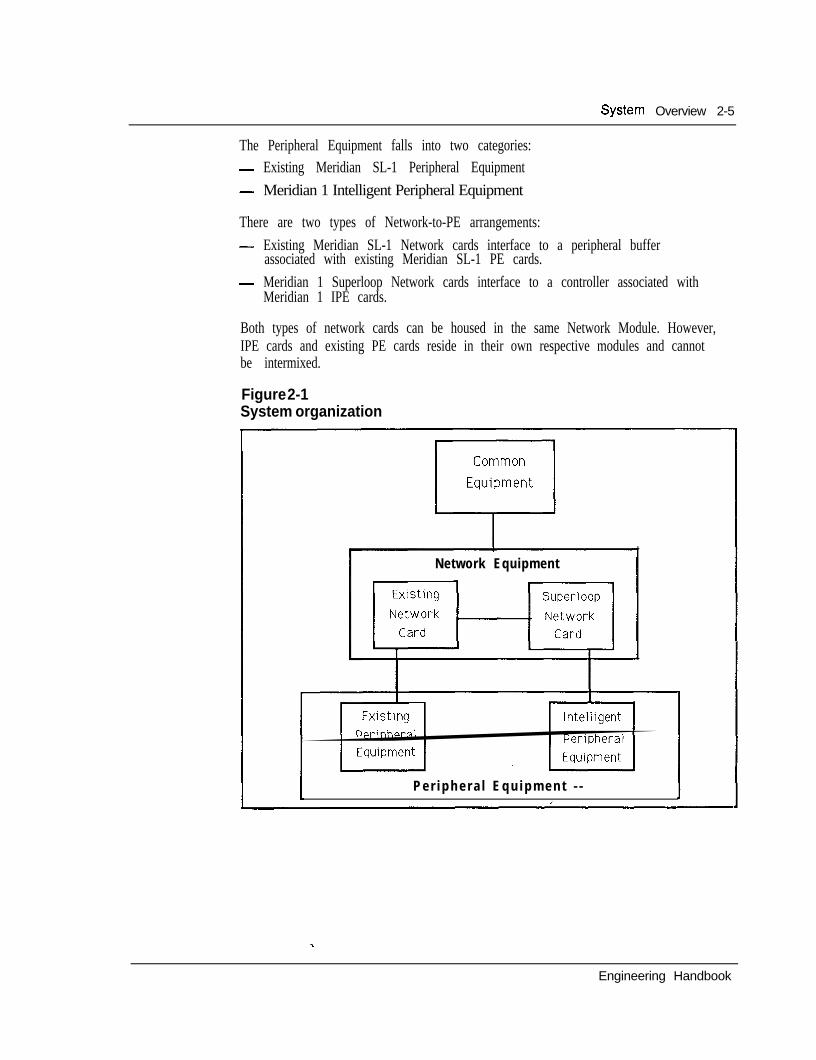
System organizationEach system option is organized around three functional partitions: CommonEquipment (which includes the system software), circuit-switched Network, andPeripheral Equipment.
Common EquipmentThe Common Equipment is comprised of the following components:- Central Processing Unit (CPU) which, under software control, provides the
computing power for system operation.- Read/Write (R/W) random access memory stores all operating software
programs and data unique to the particular SL- 1 system option includingswitching sequences, features, class-of-service information, and quantity andtype of peripheral devices.
- Serial Data Interface (SDI) provides an RS232C communications link foradministration and maintenance on either a local or remote basis.
- Mass Storage Unit (MSU) provides for high speed loading of the systemoperating software and data into the R/W memory.
NetworkThe Network consists of:- digital switching matrix for circuit-switched connections to associated
peripheral devices- two types of Network cards:
l Existing Meridian SL-1 Network cards, each supporting a dual-loopconfiguration where each network loop consists of thirty-two 64 Kbpstimeslots (30 traffic, 1 signaling, and 1 spare).
l Meridian 1 Superloop Network cards, providing 120 timeslots of 64 Kbpseach, supporting from one to eight segments over one or two IPE modules.
- Digital service circuits which provide functions such as tones and cadences andconferencing capabilities.
- Arrangement whereby the network loops are provisioned to suit the followingconfigurations:l half network group (up to 16 network loops)9 full network group (up to 32 network loops)l multi-network groups (up to 160 network loops)
Peripheral Equipment -
Peripheral Equipment (PE) performs the interface function for the telephones,terminals, and trunks that utilize the 64Kbps clear channel bandwidth capability ofthe circuit-switched network. Where necessary, analog to digital conversion (andvice versa) is accomplished on a per port basis by means of a single channel codec(coder-decoder) located on the appropriate interface cards. An exception to this isthe Meridian family of digital telephones, which reside on the PE, but includeindividual codecs built into the set for cost-effective data capabilities.
System Overview 2-5
The Peripheral Equipment falls into two categories:- Existing Meridian SL-1 Peripheral Equipment- Meridian 1 Intelligent Peripheral Equipment
There are two types of Network-to-PE arrangements:- Existing Meridian SL-1 Network cards interface to a peripheral buffer
associated with existing Meridian SL-1 PE cards.- Meridian 1 Superloop Network cards interface to a controller associated with
Meridian 1 IPE cards.
Both types of network cards can be housed in the same Network Module. However,IPE cards and existing PE cards reside in their own respective modules and cannotbe intermixed.
Figure 2-1System organization
Network Equipment
P e r i p h e r a l E q u i p m e n t - -
Engineering Handbook
2-6 System Overview
System optionsFour Meridian 1 system options, based on the Meridian SL-1 architecture, may beselected to meet various applications.
System option 21System option 21 consists of a single CPU with error correcting memory and up to28 loops (service circuits reduce this to a maximum of 24 voice/data loops). Alsocontained within the module are ten IPE slots and an interface, theNetwork/Digitone Receiver (DTR) card, which provides 120 timeslots to those IPEcards and eight DTR circuits. Growth up to 800 ports is achieved through theaddition of Superloop Network cards and IPE Modules/cards. Existing dual loopnetwork cards continue to be supported and a module designed to support MeridianSL- 1 Peripheral Equipment connects to these cards.
Another version, system option 21A, using AC power and supporting 160 ports in asingle-module-only configuration, is also available to address small systemapplications. A field upgrade kit can be utilized should growth beyond the singlemodule be required.
System option 51System Option 51 consists of a module containing CPU and half network groupfunctions, as well as the number of IPE or PE Modules required to support up to1000 ports. CPU functions are supported using the Omega processor and the eightnetwork slots which are configurable with either dual loop network cards orSuperloop Network cards, to support a maximum of 16 loops (service circuitsreduce this to 14 voice/data loops).
System option 61System option 61 adds a CPU/Network Module to the system option 51configuration to produce a fully redundant configuration, capable of supporting upto 2000 ports. This system option provides a full network group with up to 28 loops(assuming duplicated service circuits) to support voice/data requirements and theability to process up to 32,000 busy-hour call completions.
System option 71System option 7 1 is a fully redundant CPU/memory configuration capable ofsupporting up to 10,000 ports connected to (up to) five network groups. Again,both Meridian SL-1 dual loop networks and associated peripherals are supportedalong with the Superloop Network card. Assuming duplicated service circuits oneach network group, 140 of the available 160 loops may be equipped to supportvoice/data requirements.
With the exception of system option 21A, all system options listed above areavailable with either AC or DC power arrangement.
Engineering Handbook
System Overview 2-7
Features and servicesMeridian 1 capabilities range from voice and data communications for a single site,to sophisticated multi-site networking, to high capacity tandem switchingapplications. The Meridian 1 portfolio offers a complete family of desktopproducts, a full complement of voice and data communications options, easy to usesystem administration capabilities, and an extensive array of call processingfeatures. Networking capabilities range from simple off-premise extensions to localarea networks, to sophisticated corporate networks deploying ISDN Primary RateAccess (PRA), Call management applications range from simple call distribution tosophisticated call center management and reporting tools.
Meridian 1 Communication Systems extend the high performance and reliability offully digital communications across the business spectrum, to manufacturers, thefinancial community, educational institutions, government, hospitals, emergencyservices, the entertainment and hospitality industries, and any other organizationthat relies on fast, efficient communications.
The versatility and flexibility of the Meridian 1 provide optional configurations tomeet the application requirements of various business organizations. Applicationdriven technology helps reduce, control, and forecast operating costs, enhance andincrease service levels to customers, increase new business opportunities, introducenew products, and help streamline business processes to run more efficiently.
Meridian softwareMeridian software offers the same features and functions on all SL- 1 system optionsranging from small 30 port systems to systems accommodating 10,000 ports.
A comprehensive selection of features addresses the needs of all businessorganizations. Virtually every industry application (such as lodging, hospitals,finance, education, manufacturing, multi-tenant) benefits from the many time- andmoney-saving specialized features of the Meridian 1 Communication Systems.Some of these features are:- Basic Automatic Route Selection (BARS) - lowers long distance charges by
automatically placing calls over the most economical route available.- Call Detail Recording (CDR) - provides cost accounting information for
billing back to departments or individuals. Call records are available for bothinternal and external calls. In addition, CDR provides information that canassist in the management of network efficiencies. -
- Call Party Name Display (CPND) - provides users equipped with displaytelephones with the source of a call, the reason for its redirection (such as no-answer, busy), and even the identification of the party who forwarded the call.
- Multi-Tenant - allows the resale of Meridian services and features to tenantsat the same facility, with either shared or dedicated access to facilities.
- Flexible Dialing Plans - allow selection of up to 7-digit extensions and permitenormous flexibility in designing network dialing plans for multiple sites.
Engineering Handbook
2-8 System Overview
Many other time and money saving applications can be deployed with auxiliaryprocessors for sophisticated system management and administration, for inboundcall center management and reporting, for conference bridges and specializednetwork functions.
Northern Telecom’s commitment to ongoing software feature development keepssystem capabilities current with state of the art functionality to address ongoingmarket requirements. A single software development stream ensures that allfeatures are exercised on all installations, small or large, single site or multi-site:
Desktop productsToday’s advanced Meridian 1 line of products includes a telephone or terminal forevery business communications need. The Meridian Digital Telephone portfoliobrings the powerful value-added features and services of Meridian 1 to everydesktop. Simple access to voice messaging, data communications, least costrouting, and other call processing features ensures a full return on thecommunications investment .
The modular design of the telephone portfolio delivers the ultimate flexibility toconfigure a set for every user in the business organization. The modular units canbe factory or field installed to meet initial or later needs. Optional 2 x 24 LCDdisplays deliver enhanced functionality such as identification of incoming callinformation. Key expansion modules enable the portfolio to cover user applicationsfrom a single line to 60 lines. In addition, all Meridian Digital Telephones supportasynchronous data adapters. The Meridian product portfolio enables feature keyconfigurations to suit specific application requirements. The software commands(such as add, move, and change) are simplified because all sets use identical linecards, whether they are equipped for voice only or voice and data.
Data can be added to the Meridian Digital Telephone simply by installing theRS232-C data option into the base of the set. Voice and data signals are transmittedover a single twisted pair to a single voice/data port on the digital telephone linecard.
Meridian 1 SL-1 digital setsThe Meridian 1 SL-1 digital set portfolio includes:- The M2006 single line telephone which has one line key and five
programmable feature keys. -- The M2008 standard business telephone which has eight @ogrammable
line/feature keys and can connect with the optional data module.- The M26 16 performance-plus telephone which has 16 programmable keys as
well as fixed feature keys. The M2616 can be software-assigned with hands-free communications. Optional key expansion modules can extend this set toprovide 38 to 60 line/feature keys.
- The M2216 ACD telephone which comes with dual headset jacks that enablehigh-volume call handling capability of telemarketing group needs. Model 1
Engineering Handbook
System Overview 2-9
has two RJ-32 ports for modular electret headsets; Model 2 has one RJ-32 portfor an electret supervisor headset and one PJ-327 port for a carbon agentheadset.
- M2016S secure telephone which prevents the telephone from being used as apassive listening device in any environment in which confidential information isdiscussed.
- M2317 intelligent telephone which has a built-in liquid crystal display, 11programmable line/feature keys, and five soft keys to provide easy access tonumerous features, including step-by-step prompts for optional Meridian Mailvoice messaging.
- The M3000 touchphone which has a unique touch-sensitive liquid crystaldisplay that provides access to many features, including a customized directoryof more than 250 dial-by-name entries.
Meridian attendant consoleOne of the key benefits of Meridian 1 is the efficiency and speed of call processingcombined with ease of use at the central answering position(s). The Meridianattendant console is the optimum attendant interface for efficient high volume callprocessing. Large, easy-to-read indicators and a 4 x 40 liquid crystal displayprovide essential information required for processing calls and personalizing callanswering. The alphanumeric display provides for immediate viewing of callsource and destination information. Loop keys and Incoming Call Indicator keysallow the attendant the option to handle calls in sequence or to prioritize answeringfor specific trunk groups. An optional Busy Lamp Field provides the attendant withuser status at a glance.
The Meridian attendant console also supports attendant Message Center options.The attendant console can be connected to an IBM PC (80286,80386, or PS2) orcompatible to provide electronic Directory, Dial by Name, and Text Messagingfunctions to further enhance communications efficiency. All call processingfeatures can be accessed using the computer keyboard. Multiple PC adjuncts can benetworked in a multiple-console environment along with the ability to printmessages and directories locally or at departmental printers. The central answeringposition can become a streamlined and efficient message center with all the toolsneeded to provide a consistently accurate and timely exchange of information.
System administrationSystem Management is a vital link in ensuring the continuing effectiveness of theMeridian 1 Communication Systems. Meridian Manager-provides a user-friendly,PC-based management system to address operations and administrative functions.
Meridian Manager includes three optional modules:- Station Administration allows easy implementation of all telephone set software
commands (such as add, move, and change).- Traffic Reporting provides easy to understand reports on Meridian 1 system
performance. Specific analysis of processor, operator, loop, and trunk traffic
Engineering Handbook
2-10 System Overview
are automated, assuring the ability to easily and efficiently optimize Meridian 1resources.
- Work Order System provides planning management and control of telephonesinventory, as well as related financial statements, and a master telephonedirectory.
Meridian 1 data servicesThe Meridian 1 data product line is the most comprehensive one available with anycommunications system today. It allows terminals, workstations, and personal.computers to easily communicate with a wide range of hosts, local area networks(LANs), printers, modems and other devices via cost-effective standard telephonewiring. Meridian data services provide broad connectivity which allows users toaccess multiple networks, applications, and computers from a single terminal.
Data switching on the Meridian 1 platform is siLmple and cost effective. Hostcomputer resources can be shared and therefore more efficiently utilized, with fewerrequirements for expensive and inflexible nailed up connections. Existing dataterminals and intelligent workstations, regardless of type, connect via industrystandard interfaces such as RS232, RS422, and V.35. Meridian 1 supports bothasynchronous and synchronous data switching. Most models of terminals and PCscan be directly connected to the Meridian 1 without a requirement for data modules.Where the user application also calls for voice communications, these terminals caninterface through a Meridian Digital Telephone Data Adapter.
Meridian networking solutionsNetwork solutions can be simple off-premise extensions, or very sophisticated toaccommodate complex networking requirements for a large corporation. Meridian1 networking solutions can be implemented for initial requirements and upgradedlater to accommodate future growth.
Northern Telecom’s Electronic Switched Network (ESN) is a comprehensive privatenetworking solution that ties separate corporate communications systems into oneunified private network with features such as consistent dialing plans and advancedcall routing to reduce communication costs and optimize network performance.
With the implementation of ISDN on the Meridian 1, corporations have even morepowerful tools to substantially improve networking with even more flexibility tointegrate voice and data communications that best fit their organizational needs.ISDN introduces powerful new features and services to further enhance network
.performance to achieve even greater system flexibility.
Meridian Customer Defined Networking (MCDN) further extends NorthernTelecom’s network solutions portfolio by offering customers greater control andflexibility in hybrid networks. An unprecedented level of network serviceinterworking is provided with MCDN, allowing corporations to customize networkdesign to ensure the best application of advanced technology and service options forcomplex networking applications.
Engineering Handbook
System Overview 2-I 1
The link that connects corporate users to the many ISDN network services is ISDNPrimary Rate Access (PRA). Meridian 1 and ISDN PRA provide access to localexchange carriers through Northern Telecom DMS-100 switch and AT&T #5 ESS.It provides access to inter-exchange carriers like.MCI and U.S. Sprint usingNorthern Telecom DMS-250 switch and to-AT&T on the #4 ESS switch, and toprivate network nodes such as Meridian 1 systems.
Meridian 1 offers multi-national customers the ability to access other publicexchanges internationally. International PRA provides connectivity to publicexchanges, such as Ericcson AXE-lo, ITT System 12, Alcatel ElO, and SiemensEWSD.
ISDN Signaling Link (ISL) is a highly versatile 64 Kbps link between Meridian 1systems to cost-effectively integrate small remote locations more closely withheadquarters so any Meridian 1 can enjoy advanced ISDN services.
Meridian Link allows the Meridian 1 and the host computer to communicate witheach other in order to provide integration of voice and data communications tosupport sophisticated applications. For example, users can pop-up a screen ofcustomer history simultaneously upon presentation of that incoming call to thecustomer service agent. Meridian Link supports defacto industry standards, such asX.25,3270 SNA and LAPB for connectivity to IBM, Digital EquipmentCorporation, and Hewlett-Packard computers.
Meridian Networked ACDBusinesses with just two locations, or multi-national organizations with multiplesites can reap the benefits and advantages of Meridian Networked ACD. Thesystem manages the call traffic as specified by the guidelines, allowing themaximization of all resources and control of operating expenses. Automatic loadbalancing optimizes and prioritizes calls across the network so that callers who havebeen waiting the longest will get answered first. If business requirements demand24-hour operation, advantage can be taken of resources in different time zones, thusimproving customer service and increasing productivity.
The powerful Meridian features and benefits can be applied to the entire MeridianACD network. Network Ovefflow Routing provides peak period service across thenetwork, and network-wide information becomes available to agents andsupervisors.
Meridian Mail -The unique integration of Meridian Mail to the Meridian 1 Communication Systemsgives it powerful voice messaging and voice processing capabilities.
Meridian Mail delivers numerous functions with flexibility and integration betweenthem to provide a powerful office automation and marketing tool. Voice messagingallows for non-simultaneous verbal communication. The telephone-answeringfunction forwards incoming calls to the messaging system under no-answer
2-12 System Overview
situations. Callers still receive personal attention by hearing a personalized greetingwhereupon they can simply leave a message with the Voice Mail function, or at thepress of a button, be transferred to an attendant, or another designated answeringposition. Optionally, callers can route themselves to any another person by inputingthe proper extension.
Message Waiting notification advises users to collect their messages. Theautomated attendant answers calls with a recorded announcement. Call routingenables the callers to route themselves to an extension number or an informationmailbox to listen to prerecorded information Interactive voice response allowscallers to retrieve or leave information on a host computer via the telephone keypad.
The Meridian Mail networking option supports from 2 to 500 Meridian Mailsystems in remote locations. It enables users at remote sites to reply to voicemessages and utilize distribution lists that contain users on other systems across thenetwork. All features are presented and operate transparently to the user.
The Meridian Mail system is installed within the Meridian 1 CommunicationSystems module. Its multi-module design can expand to meet growth requirements.Meridian Mail can expand from 4 ports, 5 hours, to 48 ports, 240 hours of storageand can support up to 3,700 users, depending upon the application Integration tothe Meridian 1 system is through the Meridian Link for superior integration anddigital connectivity for voice quality. Connectivity to a network loop on a networkcard eliminates the need for additional hardware such as line cards. Meridian Mailcan share the battery back-up and power supply of the Meridian 1 for costefficiency.
Meridian LANSTARMeridian LANSTAR provides a most effective data network transport and topologyfor creating an establishment-wide local area network. It connects large numbers ofusers that may be spread over long distances to create a manageable and cost-effective LAN. With LANSTAR bridged via the Meridian 1, customers canimplement LAN to WAN networking (local area networking to wide areanetworking).
Based on a star topology, LANSTAR uses inexpensive standard unshielded twisted-pair telephone wiring to provide a high speed 2.5 Megabit communications linkbetween the transport hub and network users.
The modular design allows even small networks to take advantage of LANSTARsuperior distance and performance capabilities.
LANSTAR 40 Megabit data transport supports up to 1,344 users connected to thehub in a true physical and logical star topology. Users can be widely dispersed upto 609.6 m (2,000 ft) away from the LANSTAR hub for a network span of 1219.2 m(4,ooo fo.
System Overview 2-13
With the newly announced fiber optic interface, multiple LANSTAR hubs can beinterconnected to provide even greater distance capabilities for very large,geographically dispersed networks. The LANSTAR FDDI Interface allows access ’to a lOO-Megabit fiber backbone, providing very high-speed communicationsbetween each LANSTAR hub.
Users have dedicated access between the workstation and the hub, and there is noconnection for network access as there is with Ethernet or Token Ring. The startopology minimizes wiring problems and complexities. Fault isolation is easy, anda problem at one connection cannot affect anything else on the network; therefore,network reliability is very high.
Engineering Handbook

2-14 System Overview
Engineering Handbook
3-l
Chapter 3: Product evolution _ContentsThe Digital WorldThe Intelligent UniverseOPEN WorldMeridianMeridian 1System evolution
Common Equipment enhancementsNetwork enhancementPeripheral Equipment enhancements
Software evolutionSoftware Generic 101Software Generic X02Software Generic X03Software Generic X04Software Generic Xl4Software Generic X07Software Generic X05Software Generic X09Software Generic Xl 1Generic Xl 1 Release 2Generic Xl 1 Release 4Generic Xl 1 Release 5Generic Xl 1 Release 7Generic Xl 1 Release 8Generic Xl 1 Release 10Generic Xl 1 Release 11Generic Xl 1 Release 12Generic Xl 1 Release 13Generic Xi 1 Release 14Generic Xl 1 Release 15
3-33-33-33-33-43-53-73-73-8
3-l 13-l 13-l 13-l 23-l 23-l 33-l 33-l 43-l 53-l 53-153-l 63-l 73-183-183-193-193-203-203 - 2 13-22
Engineering Handbook
3-2 Product evolution
In the early seventies Northern Telecom recognized the need for a versatile state-of-the-art product that could adapt readily and quickly to changing conditions, aproduct that would give it an edge in a very competitive marketplace. The SL-1PABX (Private Automatic Branch Exchange) emerged, featuring a digital switchingmatrix under computer control.
The foresight of the original development team continues to pay dividends. Thechallenge was to design a system that would meet current needs while retaining theability to evolve without obsolescence. The key aspect of the system design is amodular, highly flexible architecture in which the primary system elements can beindependently changed in whole or in part to address changing market requirements.
The system met an immediate demand for a full range of voice and data processingfeatures in a cost-effective package. Besides functioning as a Private BranchExchange (PBX), it also included key telephone and custom calling features. Theseadvances were achieved by incorporating several notable industry firsts. A highlevel software language (HLL) provided significant advantages over assemblerlanguage in terms of simplicity and implementation. It also permitted improved,simpler ways for users to communicate with the system.
To complement the advanced PBX features, a custom LSI chip was incorporatedinto a proprietary electronic telephone and its associated peripheral interface. Froma human factors point of view, replacing the conventional telephone with a newelectronic set was a prerequisite for more effective business communicationsservices. The SL-1 electronic telephone provided simple, direct selection offeatures, and unambiguous system responses to indicate the progress of calls.
The main objective to reduce the size of interconnecting cable as compared to thoseused for existing key telephone sets, was achieved by using a form of distributedcontrol in the SL-1 set. The six-conductor line cord in the latter permitted systemsto be pre-cabled irrespective of the eventual use of either SL-1 or conventional500/2500 type single line telephones at a terminal location.
Another industry first was the utilization of the codec on a per port basis to take fulladvantage of digital technology. Ongoing silicon enhancements could beintroduced without affecting more centralized equipment in the system. Peripheralequipment was packaged in increments of four line circuits and two trunk circuitson associated individual cards.
-The first system shipment was in 1975, and the product has continued to evolve,incorporating new technologies as they became available. As a result, a continuousstream of enhancements has introduced a series of system models, each buildingupon its predecessor with improvements in performance and capabilities.
All models in the product family share similar technology and hardware, as well assoftware. They differ only in hardware packaging and the number of peripheralterminations that they support. The wide variety of available models ensures thatusers can select the system and features best suited to meet their specific needs.
Engineering Handbook
Product evolution 3-3
The Digital WorldIn 1976, Northern Telecom became the first corporation to commit publicly, withthe Digital World announcement, to producing a complete line of digital switching,business communications and transmission systems. Every majortelecommunications manufacturer has since followed this lead. Today, NorthernTelecom is the principal supplier of fully digital systems in the world. Its family ofdigital business communications systems is among the world’s most advancedmulti- function integrated voice and data switching systems.
The Intelligent UniverseIn 1979, Northern Telecom unfolded the Intelligent Universe to announce thethreshold of a new era for its product capabilities. Envisioned were newapplications of digital technology to create efficient, harmonious global networks ofsimultaneous voice and data transmission that allow major office communicationfunctions to be undertaken in a single integrated system. In addition, the formationof sophisticated networks would evolve to provide comprehensive communicationsthrough intelligent terminals in which information can be organized, stored,accessed, and received from any source in the world.
OPEN WorldIn 1982, Northern Telecom announced the OPEN World for informationmanagement systems, The OPEN (Open Protocol Enhanced Networks) World wasan extension of Northern Telecom’s proven expertise in the key areas of digitaltechnology, semiconductors, software, and integrated communications capability. Itpresented a commitment to providing a planning framework, new products, featuresand services for the OPEN World.
Northern Telecom’s announcement of OPEN World promised to create integratedcommunication networks that open the technological barriers to user-controlledsystems. The SL-1 would act as the hub for such systems, giving the user theopportunity to install whatever equipment is most cost-effective for the application.The OPEN World concept encompasses the following five key criteria: continuity,compatibility, congeniality, control, and cost-effectiveness.
MeridianOn February 14, 1985, Northern Telecom, in keeping with the OPEN Worldpromise, announced major enhancement capabilities to itsSL family of digitalswitching systems. Under the banner of Meridian SL-1 Integrated ServicesNetwork, a new range of sophisticated information management services wouldevolve including:- a local area network (LAN) capability called LANSTAR- a unique, high speed 2.56 Mbps pipeline to the desktop using conventional
twisted pair wiring distribution- a range of fully digital telephones to increase the existing terminal portfolio
using a new 512 Kbps digital distribution schemeY . .
Engineering Handbook
3-4 Product evolution
The foregoing enhancements were accomplished through architectural extensionsthat built upon the existing system foundation. As such, they reemphasizedNorthern Telecom’s commitment to a continuity program that guards againstproduct obsolescence.
Meridian 1On January 30,1990, Northern Telecom unveiled Meridian 1, a modularcommunication system encompassing the industry’s first truly global private branchexchange (PBX) product line.
Meridian 1 represents a merger of the functionality of Meridian SL-1 and MeridianSL-100, and Meridian SuperNode, Northern Telecom’s current PBX products, into asingle, modular communications product portfolio. Meridian 1 capabilities extendfrom voice and data features for very small organizations to high capacity advancedtandem networking, very large Automatic Call Distribution (ACD) centers, (up to4,000 agents), multi-function military agency support, campus communicationsystems, intelligent network node capabilities, and the bridge to the FiberWorld ofthe future.
The new Meridian 1 provides common hardware and adaptive software for existingsystems. This means that customem can upgrade to the latest voice features, dataconnectivity, and sophisticated information services for PBX applications ranging insize from 30 to 60,000 ports, the widest range in the industry, while retaining 80 to90 percent of their equipment.
Noteworthy for multi-national corporations, Meridian 1 uses globally adaptivetechnology that enables it to be sold and used in virtually any country without majorhardware modifications. Meridian 1 software is compatible with recognizedinternational communications transmission standards. Additionally, Meridian 1digital telephone sets can be programmed to give instructions in six languages.
Meridian 1 provides a platform for future growth and will be compatible withcommunications networks of the next century. Underscoring Northern Telecom’sleadership in ISDN, Meridian 1 delivers ISDN primary rate access (PRA) now. Itsupports Basic Rate Access (BRA) on large systems and will deliver BRA acrossthe entire product line by the end of 1991. In the future, the new system will usefiber optic technology to provide broadband capability, bandwidth on demand andservices such as high speed data and full motion video. - -Northern Telecom Meridian 1 introduces a product design consisting of newstackable modules that contain the various system elements. Peripheral EquipmentModules contain line and trunk cards that connect a wide variety of telephone andcentral office interface circuits.
The new modular design offers the ability to grow from a single module through acolumn of up to four modules into an array of columns that connect with existingequipment to extend and serve applications with up to 60,000 ports. The modular
Engineering Handbook
Product evolution 3-5
packaging takes up to 50 percent less floor space than existing systems in cabinetsand lets customers add lines and features in a simpler, more cost effective mannerthan ever before.
The core of the product line is an lntelhgent Peripheral Equipment Module thatworks with both the Meridian SL-1 and SL-100 and has distributed processing, highdensity line cards, universal trunks, improved self-diagnostics, and an enhancednetwork architecture. System options provide the ability to select the configurationbest suited to meet the required business communication application within the 30to 60,000 port range. For applications up to 10,000 ports, system options 21,5 1,6 1, and 7 1, based on the Meridian SL- 1 architecture, are available for use.
System evolutionSL-1L In 1975, Northern Telecom introduced the SL-IL as its first member. Thesystem was configured in a single network group arrangement with a choice of oneor two Central Processing Units (CPUs). Memory was packaged in modules of 4Kwords and structured in an N + 1 concept such that a spare module was available inthe event of a memory failure.
SL-1VL The SL-1VL was introduced in 1976 to address requirements beyond thecapacity of the SL-IL. It consisted of a multi-group arrangement for up to fivenetwork groups, each group capable of accommodating the 16 multiplexed loopsprovided by the SL-1L. A similar design philosophy and many of the samecomponents were used, the major differences between the two systems being in thearea of common equipment. The SL- 1VL system utilized a more powerful andduplicated CPU, a repackaged memory in modules of XK words, and a centralizedpowering concept. It was supported by Software Generic 202 which added anumber of feature enhancements over the initial system capability. The softwarewas also adapted to the SL-1L as Generic 102.
SL-1LE and SL-1VLE In 1978, common equipment enhancements capitalized ontechnological advances to effect cost reductions and increased system reliability.The result was the introduction of two new systems:- SL- 1LE for single network group applications- SL-1VLE for multi-network group applications
An increased density memory module storing 64K words of data or programinformation was introduced, drastically reducing the number of circuit cardsrequired by each system. The enhancement also inc&ed the memory addressingcapability to accommodate ongoing feature incorporation. A redundant (2N)memory bank was introduced to complement the duplicate processor capabilityalready available. Each processor was able to access both memory banks, with theflow of information to the active processor controlled by an arbitrator, a significantimprovement over the conventional use of a single memory bank with duplicatespares. In addition, the concept of segmented busses was incorporated to allow
Engineering Handbook
3-6 Product evolution
recovery of call processing functions by reconfiguring the system hardware toisolate faults.
SL-1A A significant breakthrough in equipment packaging was made in 1978.Although expandable to some 400 lines, the SL-1A emerged to address the 100 lineand below market. Spare mounting space in the equipment cabinet was utilized toaccommodate a mini-network shelf and a magnetic tape transport. Shelf positionswere thereby freed for peripheral equipment, enabling a single CPU to service 200PE terminations in a single cabinet configuration.
SL-1XL Out of the SL- 1 technology, the SL- 10 packet switching system emerged.Of significance is that the powerful processor utilized for data transmission in theSL-10 was adapted to the SL-1 to form a new family member, SL-1XL. The latterwas introduced in 1980, expanding the call processing capability through anincrease in CPU real time capacity. The SL- 1XL also provided more memorystorage to allow further penetration into the 2000-5000 line range.
SL-1M This system was introduced in 1982 and with it the concept of front andrear cabinet access to take advantage of hardware repackaging and a subsequentreduction in footprint. A single cabinet supports a typical configuration 250lines/40 trunks with expansion to a 400 line marketing limit by means of anadditional peripheral cabinet.
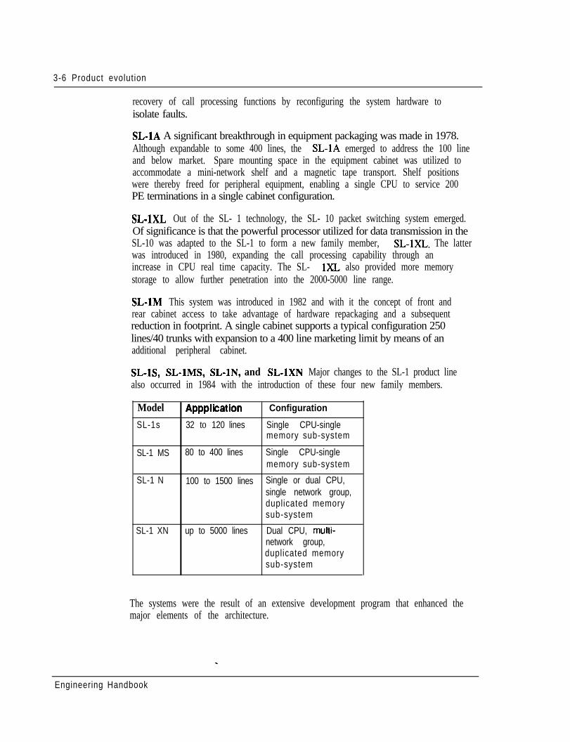
SL-lS, SL-lMS, SL-lN, and SL-1XN Major changes to the SL-1 product linealso occurred in 1984 with the introduction of these four new family members.
Model Appplication Configuration
SL-1s 32 to 120 lines Single CPU-singlememory sub-system
SL-1 MS 80 to 400 lines Single CPU-singlememory sub-system
SL-1 N 100 to 1500 lines Single or dual CPU,single network group,duplicated memorysub-system
SL-1 XN up to 5000 lines Dual CPU, multi-network group,duplicated memorysub-system
The systems were the result of an extensive development program that enhanced themajor elements of the architecture.
Engineering Handbook
Product evolut ion 3-7-
Common Equipment enhancementsThe Common Equipment (CE) enhancements consisted of redesigning the CentralProcessing Unit (CPU) and Memory sub-systems.
A new type of central processor, based upon the SL-iXL microprocessortechnology but with a much simpler architecture, was introduced for single networkgroup applications. Elimination of much of the discrete logic previously employedin separate Arithmetic Logic Unit (ALU) and Sequencer (SEQ) cards plusutilization of 64K EPROMS to store the firmware resulted in the CPUbeing housedon a single card. Thus the benefits of fewer components, less power requirements,along with a reduction in footprint were achieved without sacrificing performance.Indeed the reverse since the new microprocessor increased processing speed by asmuch as 55 percent over the equivalent earlier CPU models.
The introduction of 64 Kilobit Random Access Memory (RAM) chips permittedmemory packaging in 192K modules as opposed to the previously available 64Kmodules. Additionally, the functions of the Memory Controller, formerly a separatecard, were incorporated in the new memory module design. Two design types weredeveloped, one incorporating automatic error correction and detection capability forsystems using single memory subsystems (S and MS), and the other usingconventional 17 bit per word formatting (16 data plus 1 parity) for the duplicatedmemory subsystems (N and XN). Further, two versions of each type in 128K and192K modules were made available to facilitate memory addressing throughefficient hardware provisioning for each SL-1 family member.
Network enhancementEnhancements to the switching network were made primarily to address therequirements imposed by data communications on the SL-1 system. The existingnetwork architecture was designed for applications in what was then apredominantly analog world. As such, to simplify the path search algorithm,available time slots or channels through the network were selected on a matched-pair basis. Thus a call originating on timeslot 4, for example, always terminated ontimeslot 5 to complete the connection. This arrangement is certainly adequate forvoice switching requirements. However, the recognition of the PBX as a viable hubto control the switching of integrated voice and data demanded improvements overthe original design.
Network enhancement achieved the following: _ _- Removed the time slot matching pair constraint by selecting available channels
on an individual basis. Thus the varying traffic requirements imposed byswitching voice and data can be readily addressed by allocating networkresources accordingly to meet the specific needs of each.
- Doubled the number of links on the network backplane so that the associatedequipment shelf could accommodate twice as many network loops. This wasaccomplished by the design of a new network card containing two loops asopposed to the single loop per card employed previously. Thus the number ofnetwork loops was doubled (16 to 32) within a network group. To complement
Engineering Handbook
3-8 Product evolution
this increase in traffic handling capability, the junctures, which are merelyextensions of the originating and terminating loops between network groups,were also doubled (from 4 to 8 one-way junctures from one network group toeach other).
Peripheral Equipment enhancementsIntroduction of Very Large Scale Integration (VLSI) components was instrumentalin providing significant benefits from the PE enhancement program. In particular, anew custom filter codec chip, allocated on a per port basis, enabled peripheral carddensity to be doubled. Initial application of the chip, designated WO5, to the mostwidely used PE cards, the SL-1 and 500/2500 line types, resulted in footprintsavings and a reduction in per line power consumption. The next phase of theprogram introduced the WOS to the CO Trunk, DID Trunk and Message WaitingLine Cards respectively - again doubling the number of ports per card compared totheir previous counterparts. The WO5 met the transmission standards for digitalPBX mat are recommended by the U. S. Electronics Industries Association (EIA).These standards cover return loss, longitudinal balance, gain variation, idle channelnoise, and other transmission characteristics.
Compliance to U.S. Federal Communications Commission (FCC) Part 15regulations was mandatory for the continued marketing of the SL- 1, which isclassified as a Class A computing device. These regulations cover ElectromagneticInterference (EMI) and Radio Frequency Interference (RFI) requirements and wereaddressed at both the circuit card and system levels under the PE enhancementprogram. At the circuit card level, EM1 and RFI were minimized through designpractices that tackled the problem at the source. Use of CMOS (ComplementaryMetal Oxide Semiconductor) components, isolated circuit traces, and multilayerbackplanes were contributing factors. From the system point of view, a newequipment cabinet was designed utilizing elaborate shielding techniques to preventEM1 and RFI being emitted from the SL- 1 equipment contained therein.
Not all facets of the enhancements were applicable to all systems. Instead, portionsof the program were adapted as appropriate to benefit product application, a furtherindication of the modularity and flexibility of the SL- 1 design.
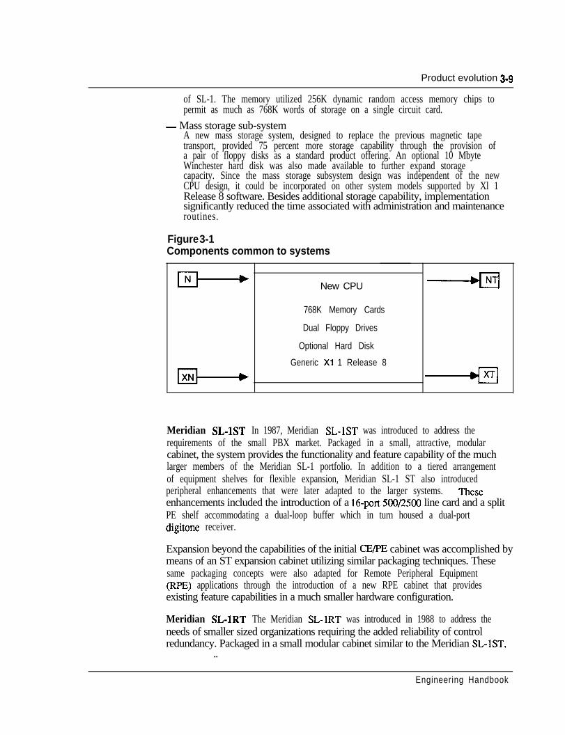
Meridian SL-lNT, Meridian SL-1XT Major system enhancements wereincorporated in 1986 as signified by the introduction of Meridian SL-1NT andMeridian SL-1XT. A Common Equipment enhancement program, supported bySoftware Generic X 11 Release 8, provided new key operating elements whichresulted in significant improvements to system operating parameters. The followingnew components were identical for use inboth NT and XT systems:- Central Processing Unit
a new CPU, contained on two printed circuit cards, provided in excess of fiftypercent more real time capacity compared to that previously available onMeridian SL-1XN.
- Random Access MemoryA new memory design increased significantly the software address range andeliminated the 64 K word page address partitions incorporated on earlier modelsU , .
Engineering Handbook
Product evolution 3-g
of SL-1. The memory utilized 256K dynamic random access memory chips topermit as much as 768K words of storage on a single circuit card.
- Mass storage sub-systemA new mass storage system, designed to replace the previous magnetic tapetransport, provided 75 percent more storage capability through the provision ofa pair of floppy disks as a standard product offering. An optional 10 MbyteWinchester hard disk was also made available to further expand storagecapacity. Since the mass storage subsystem design was independent of the newCPU design, it could be incorporated on other system models supported by Xl 1Release 8 software. Besides additional storage capability, implementationsignificantly reduced the time associated with administration and maintenanceroutines.
Figure 3-1Components common to systems
New CPU -
768K Memory Cards
Dual Floppy Drives
Optional Hard Disk
Generic Xl 1 Release 8
-----@I
Meridian SL-1ST In 1987, Meridian SL-1ST was introduced to address therequirements of the small PBX market. Packaged in a small, attractive, modularcabinet, the system provides the functionality and feature capability of the muchlarger members of the Meridian SL-1 portfolio. In addition to a tiered arrangementof equipment shelves for flexible expansion, Meridian SL-1 ST also introducedperipheral enhancements that were later adapted to the larger systems. Theseenhancements included the introduction of a 16-port 500/2500 line card and a splitPE shelf accommodating a dual-loop buffer which in turn housed a dual-portdigitone receiver.
Expansion beyond the capabilities of the initial CE/PE cabinet was accomplished bymeans of an ST expansion cabinet utilizing similar packaging techniques. Thesesame packaging concepts were also adapted for Remote Peripheral Equipment(RPE) applications through the introduction of a new RPE cabinet that providesexisting feature capabilities in a much smaller hardware configuration.
Meridian SL-1RT The Meridian SL-1RT was introduced in 1988 to address theneeds of smaller sized organizations requiring the added reliability of controlredundancy. Packaged in a small modular cabinet similar to the Meridian SL-IST,
..
Engineering Handbook
3-10 Product evolution
redundancy. Packaged in a small modular cabinet similar to the Meridian SL- lST,the RT utilized the dual CPU and memory duplicate configuration of the NTsystem. The Meridian SL-1RT could be expanded by adding the same tiersdesigned for Meridian SL-1ST expansions. _
Meridian 1 Communication Systems - system options 21,51,61, and 71Unveiled at global launch events on January 30, 1990, these systems combine thefunctionality of the Meridian SL-1, Meridian SL-100, and Meridian SuperNode intoa single, modular product line to address system applications ranging from 30 to.60,000 ports. Based upon the Meridian SL-1 architecture for applications up to10,000 ports, Meridian 1 system options 21,5 1,61, and 71 introduce the followingenhancements and features:- Modular equipment packaging- Superloop- Intelligent Peripheral Equipment- 300 percent increase in peripheral display- 25 percent increase in network traffic capacity- Seamless growth from 30 to 10,000 ports- ISDN-ready for Basic Rate Access, in addition to present Primary Rate
capabilities- Increased self-diagnostic capabilities- Extensive system and power monitoring, with intelligent reporting- Reduction of system engineering rules and constraints- Simplified installation and maintenance- Flexible power system architecture- Effective total platform for continued growth and evolution, in keeping with
Northern Telecom Evergreen philosophy
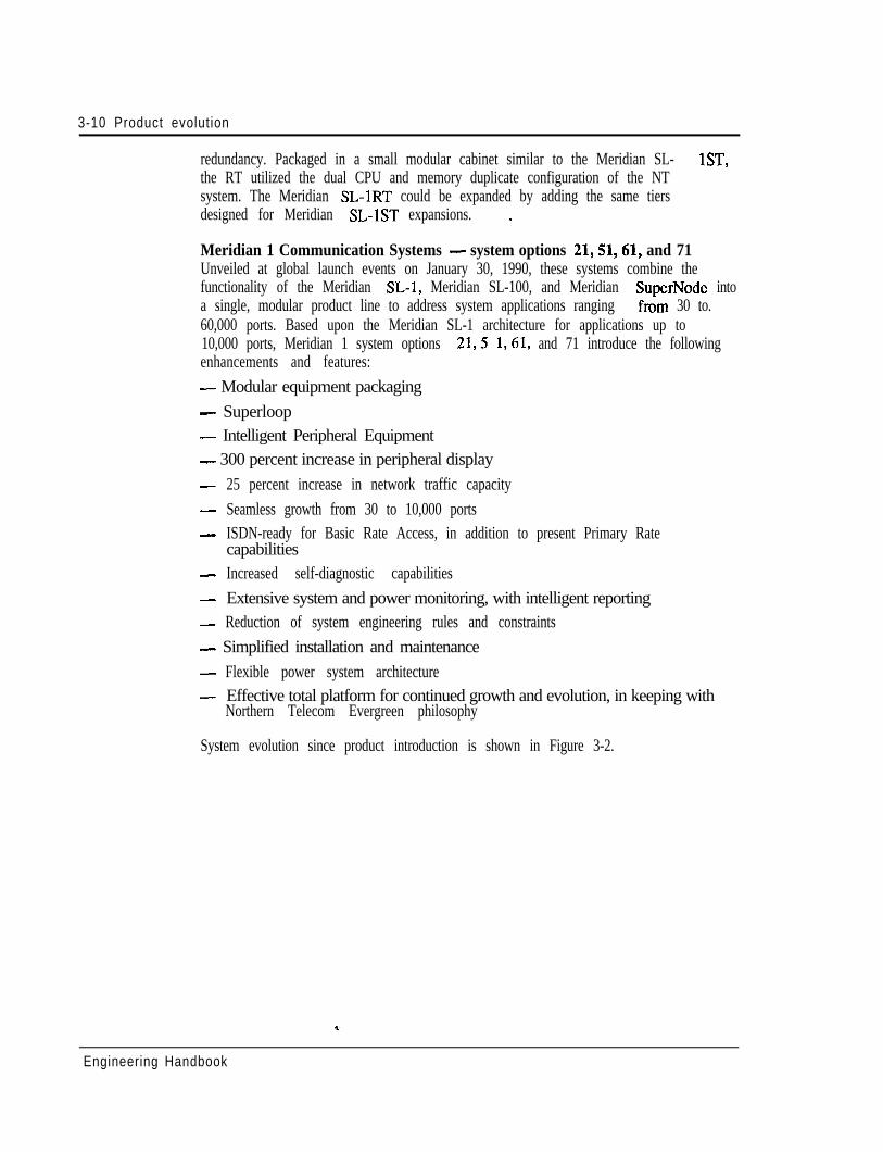
System evolution since product introduction is shown in Figure 3-2.
Engineering Handbook
Product evolution 3-11
Figure 3-2System evolution
,II ((1979)[ 1- l(las4)1)
system 0Dtion 21
M E R I D I A N 1
pL.(J H(-1(1984)1 w H+ sL-l1system option 51
I> ” . Y
-11 I
\,.,,.,,
‘i”
w -w +q-.q1;,;..1
COMMUNICATION SYSTEMS
Software evolutionSeveral software generics were introduced throughout the years to support thevarious features.
Software Generic 101From a software point of view, Generic 101 was introduced to support the SL-1Lsystems. In addition to many standard features and services inherent in the system,optional software packages provided multi-customer and advanced SL-1 setfeatures. Multi-customer was unique in that it allowed a single SL-1 system toserve up to 32 different customers, each with independent feature complements,numbering plans, and peripheral equipment. The advanced feature packageprovided Auto Dial, Call Forward, Override, Ring Again, Speed Call, and VoiceCall capability to the SL-1 telephone user. The typical application of the SL-1Lsystem was in the 100 - 1000 line range.
Software Generic X02Generic 202 was introduced in 1976 to form the base for the SL-1 VL system. Thesoftware added a number of feature enhancements over the initial system capabilityand was adapted to the SL- 1 L as Generic 102.
U . .
Engineering Handbook
3-12 Product evolution
Software Generic X03Significant changes were made to the software in 1977. The following majorfeature complements were made available under Generic X03.
Call Detail Recording (CDR)Allows the recording, on a per call basis, of details related to incoming and outgoingcalls such as the calling and called parties, time, and duration. The information isassembled by the software and stored as call records on either a g-track magnetictape mounted in a CDR cabinet, hard-copy device such as a teletypewriter, orexternal unit conforming to RS-232-C interface. Downstream processing of thecollected data permits usage reports to be generated.
Recorded Announcement (RAN)Provides an interface to a Recorded Announcement machine and the capability offlexibly defining the intercept treatment for various call situations.
Time and DateProvides the capability of displaying and modifying the system time and date fromthe attendant console.
Do-Not-DisturbProvides the capability for the attendant to make any individual directory numberappear busy to incoming calls while maintaining it free for originating calls.
End-to-End SignalingAllows the use of the SL- 1 electronic telephone on an established outgoingconnection to utilize the pushbutton dial pad to effect Digitone end-to-endsignaling.
Software Generic X04Generic X04 was also introduced in 1978 with the addition of further optionalfeature groups.
Automatic Number Identification (ANI)Provides the facility to automatically identify a station originating an outgoing tollcall and to send this information by Multi-Frequency (MF) signaling to a centraloffice toll-ticketing system. The feature is implemented by a combination ofsoftware and hardware, the latter consisting of an MF sender, .located on theswitching network bus, interfacing to an associated AIVI trunk group.
Route Selection - ANI (RS-ANI)Works in conjunction with the ANI feature to route toll calls automatically overpredetermined trunks.
Engineering Handbook
Product evolut ion 3- l 3
Automatic Route Selection (ARS)Provides automatic selection of least expensive and efficient trunk routes undersoftware control for outgoing calls. The ARS mechanism is accessed by dialing aspecial access code and arranged to route advance a call over up to eight trunkroutes under two different time schedules.
Remote Peripheral Equipment (RPE)Increases the range of the multiplex loop between the CE and PE by using Tl typecarrier facilities. The 2.048 Mbps local network loop is converted to a’ 1 S44 Mbpsformat for transmission to a remote location and then reconverted back to 2.048Mbps to interface to the RPE.
Do-Not-Disturb: GroupAllows the attendant to place a group of directory numbers into a Do-Not-Disturbmode so that they appear busy to all incoming calls, but free to originate calls.
Make Set Busy (MSB)Allows an SL-1 telephone user to busy out the set for incoming calls to all DNappearances but free to originate calls.
The demand for additional system features was so great that in 1979, a split in theSoftware Generic occurred to address specific market segments. Business GenericX04 formed the foundation for the separate generic streams to evolve.
Software Generic Xl 4Generic Xl4 was introduced for SL-1 interface to the Autovon (Automatic VoiceNetwork) to present Northern Telecom with a key marketing strength in supplyingthe military and government market with a proven cost-effective system. The SL-1Autovon system provides full-featured PABX capabilities combined withrequirements of the Defense Communications Agency (DCA) Circular 370-V1756specifications, such as precedence and pre-emption of calls.
Software Generic X07Generic X07 was aimed specifically at the Hotel/Motel communicationsmanagement market. The full business features of X04 were incorporated with newfeatures designed to provide additional hotel administration and managementfunctions such as: - -- Room Number Correlation ,’
- Single Digit Access to Special Services- Message Waiting- Vacant Room Restriction- Supervisory Attendant Console- Toll Terminal Access
Engineering Handbook
3-14 Product evolution
- Music-On-Hold- System Call Park- Room Status- Control Class-of-Service- Recorded Overflow Announcement
Software Generic X05Additionally, Generic X05 was introduced as the premium Business Generic,adding the following major capabilities.
Automatic Call Distribution (ACD)Provides a means of sharing service among a group of answering positions such thatcalls are served in the order of their arrival. A number of administration capabilitiesare available for effective agent/supervisor communication. The flexibility ofproviding stand-alone ACD, combined PABX service, or a split among the two canbe configured utilizing a single SL- 1 system.
ARS - Priority QueuingProvides an improvement to the ARS feature by introducing a flexible class-of-service assignment of one of four priority levels for the access of least cost routesby each user.
Authorization CodeAllows selected users to temporarily override the access restriction assigned to anystation or trunk by entering an authorization code.
CDR Charge Account CodeAllows a charge account code to be entered before dialing or during an establishedcall to allow billing of calls to other than station directory numbers.
Centralized Attendant Service (CAS)Allows customers with multiple locations to centralize their attendant services at asingle facility. Operation is compatible with AT&T Technical Advisory Manual 10(TA-lo), with the SL-1 system serving as either a main or remote CAS installation.
Digit Display _-Provides for the display of information relative to normal call processing andfeature activation on any SL- 1 telephone equipped with a digit display.
Dial IntercomAllows stations to be accessed by abbreviated dialing and be arranged into separateintercom groups within the SL-1 network.
Engineering Handbook
Product evolution 3-15
Direct Inward System Access (DISA)Allows selected users to access the SL-1 from the external public network bydialing a special directory number from any’Digitone type telephone.
Message CenterAllows an incoming call to be automatically routed to a message center if notanswered at the original destination. A message waiting indication alerts the stationuser, who can then access the center for message retrieval.
2500 Set FeaturesProvides a subset of features, formerly available only to SL-1 telephones, to beutilized on 2500-type single line sets. A Special Prefix Code (SPRE) is used inconjunction with the octothorpe.key (#) to activate the following features:- Call Forward (All Calls)- Speed Call (User and/or Controller)- Permanent Hold
Software Generic X09Software Generic X09 was introduced in 1980 to support the SL-1XL andadditionally provide enhancements to the ACD feature by adding load managementadministration and report capabilities.
Software Generic Xl 1A new business Generic stream Xl 1 was utilized to support SL-1M under 711,Release 1, which provided all the feature capabilities of its predecessors and addednew capabilities aimed towards the small system user. These new capabilities were:- Attendant Overflow Position- Mini-CDR- History File- System Memory Automatic Recovery Technique (SMART)- Attendant Administration- Automatic Set Relocation
These feature enhancements, with the exception of mini-CDR and SMART, werelater made available to the LE, VLE, and XL systems. - -,’
Generic X11 Release 2Xl 1 Release 2 was introduced in early 1983 to add the following featureenhancements to the M, LE, VLE and XL systems.
Engineering Handbook
3-16 Product evolution
Call ParkProvides the capability for attendant or station user to place a call in a held state(park) where it can be retrieved by dial access from any console or telephone set inthe system.
System Speed CallAllows the creation of a System Speed Call list (or lists) for access by any assignedstation set irrespective of any class-of-service restrictions.
Recorded Overflow AnnouncementAllows incoming calls that are delayed in answering by the attendant to be routed toa recorded message notifying the caller accordingly.
Flexible Code RestrictionAllows the customer to specify whether stations with toll-denied class of servicewill be allowed or denied access to outgoing trunk routes based on specific numberpatterns and/or the number of digits dialed.
Extensions to the ACD capabilities were announced in 1983 with the formation ofan additional feature group - Package D. The latter is utilized for large ACDoperations that require sophisticated management reports and flexible dynamicresource allocation capabilities. ACD-D uses an auxiliary data system (DigitalEquipment Corporation PDP-11 minicomputer) attached to the SL- 1 to provide acomprehensive administration capability that includes status displays, reports, andload management functions.
Generic Xl 1 Release 4In 1984, Xl 1 Release 4 became the business software standard and incorporatedthe Autovon capability previously only available on X14. The following additionaloption groups became available.
Flexible HotlineProvides the capability to assign any single pre-determined destination to beautomatically rung from an associated 500/2500 telephone when the latter goesoff-hook.
Deluxe HoldAdds two capabilities for calls placed on hold in multiple appearance (single callarrangement) directory number environments:- Individual Hold - held condition is indicated at the normal 120 ipm on the
SL- 1 telephone that placed the call on hold only. All other appearances of theDN receive a slow flicker (50 ms off every 2 seconds).
- Exclusive Hold - allowed users with multiple appearance DNs to place callson hold under the control only of their particular telephone. All otherappearances of the DN do not indicate the held call and are excluded fromentering it. u .
Engineering Handbook
Product evolution 3-l 7
Automatic Line SelectionAllows the SL-1 telephone to automatically select a line in a prioritized order whenthe handset is lifted.
500 Set FeaturesProvides rotary dial access to the Speed Call, Call Forward, and Permanent Holdfeatures.
Distinctive RingAllows calls over specified trunk routes to distinctively ring stations as opposed tothe standard audible signaling arrangement.
Integrated Voice Messaging System (IVMS)Expanded previous SL-1 capabilities to. include voice store and forward (VSF)messaging.
Generic X11 Release 5Xl 1 Release 5 was introduced during the second quarter of 1985. It consists of allthe capabilities of Release 4 plus the following feature enhancements.
Business features- Interface to EPSCS (Enhanced Private Switched Communications Service) - a
Private Network of AT&T which uses the No. 1 ESS as a switching host- Departmental LDN feature - allows up to four different departments to be
identified by their own spccilic listed directory number- Data Port Hunting - allows up to 128 data access modules to be assigned in a
trunk group- Privacy Override - allows multiple-appearance, single-call-arrangement
directory numbers assigned to SL- 1 telephones to have class-of-service controlof privacy
- Enhanced End-to-End Signaling - allows this capability to be invoked on allcalls to and from the SL-1 telephone
- Call Register Enhancement - allows a separate logical memory page to beassigned to both call registers and trunk timing blocks, thereby increasing thenumber of call registers from 1200 to approximately 1500
- Double Density Trunks (CO and DID) and Message Waiting Line Cards -allows twice as many circuits to be packaged on,a single card compared to theirsingle density counterparts
- Memory Enhancement - increases the amount of memory available on theSL-1XN in the areas of Program Store and Protected Data Store
Engineering Handbook
3-18 Product evolution
ESN features- Offnet Number Recognition for BARVNARS feature - removes the need to
use two additional CO trunks to terminate a call at a company owned location- Incoming Trunk Group Exclusion - associated with the BARS/NARS feature,
provides the capability to deny the routing of incoming trunk calls to specificprefix codes
- Multiple DID Office Code Screening for NARS - supports on-net to off-netconversion for sites having varying numbering schemes
Generic Xl 1 Release 7Xl 1 Release 7 was introduced to support the following feature capabilities:- Controlled Class of Service (CCOS), formally introduced for the Hotel/Motel
industry, was applied to the business environment to allow a station’s level ofaccess to the external network to be changed. to a predetermined system levelusing a controlling SL-1 telephone.
- Multi-Tenant Service allows each of the 32 customer groups within theMeridian SL-1 to be partitioned into 5 12 tenants to facilitate resale of services.
- Automatic Trunk Maintenance provides a means of periodically testing networkresources by measuring facility loss and noise parameters to prevent under-utilization due to poor performance or service outage. Associated hardware toprovide tone detection capabilities was also introduced.
- Station Category Indication (SCI) allows the attendant to selectively answerinternal calls in accordance with a predetermined priority status.
Generic Xl 1 Release 8Xl 1 Release 8 provided additional system capabilities as follows:- Digital Trunk Interface (DTI), formerly introduced on Meridian SL-1N and XN,
was extended to include the smaller sized MS system and also NT and XTmodels.
- Last Number Redial (LNR) allows users to simply redial the last number dialedwithout having to key in the digits again.
- Pretranslation provides a means of utilizing Speed Call lists to implement aflexible dialing plan.
- Supervisory Console allows one attendant in each customer group to function ina supervisory capacity when the associated console is placed in a position-busymode.
- Eleven-Digit Translation extends the previous three- or four-digit translationmechanism to eliminate potential routing conflicts when utilizing theBARS/NARS feature.
- Sixty-three Attendant Consoles are allowed for each customer group comparedto the previous fifteen.
- Station-to-Station Call Waiting allows internal calls to enter the call waitingstate via a new station class of service.
Engineering Handbook
Product evolution 3-19
Generic Xl 1 Release IOAnother major announcement was the availability of Xl 1 Release 10 for the firstquarter of 1988. This software release introduced new business opportunities in keyvertical markets such as lodging, health care, telemarketing, and the federalgovernment. In addition, Generic Xl 1 Release 10 culminated the developmentprogram, embarked upon in 1984, to recombine the Hotel/Motel Generic (X37) intoa single stream business offering. Thus users in the lodging environment utilizedfeatures formerly only available to the business segment, and vice versa. GenericXl 1 Release 10 introduced a total of 16 new feature options, partitioned typicallyfor vertical markets, but additionally available to all users of this software base.
Hospitality/health care
- Automatic Wakeup- Room Status- Message Registration- Property Management System Interface- Background Terminal
Federal systems telemarketing- Station Loop Pre-emption- ACD Enhancements- Line Load Control - Call Overflow by Time in Queue- Dialed Number Identification Service
General business
- Call Party Name Display- Call Forward No Answer/Hunt by Call Type- Second Level Call Forward No Answer- Six Party 2500 Set Conference- Enhanced Hotline- Station-to-Station Call Detail Recording- Malicious Call Trace
Generic X11 Release 11 -The introduction of ISDN Primary Rate Access (PRA) capability was madeavailable in 1988 with the revision of Xl 1Release 11 as the supporting software.
Another enhancement to the system features was the ability to perform digitmanipulation on incoming direct-in dial calls.
Engineering Handbook
3-20 Product evolution
Generic Xl 1 Release 12Generic Xl 1 Release 12 was introduced in November, 1988, to offer another subsetof powerful features to Meridian SL-1. The delivery .of ISDN services, console andACD enhancements, further data networking flexibility, specific features for HealthCare and Hotel markets, additional business feature offerings and memoryexpansion for the Meridian SL-1 ST all combined to bring new services. Thefollowing features were provided with this release:- Automatic Call Distribution Auxiliary Security (ACD-D)- Automatic Call Distribution Priority Agent- Enhanced Music (EMUS)- Directed Call Pick-up (DCP)- Call-by-Call Service (CBC)- ISDN Signaling Link (ISL)- ISDN Advanced Features (IAF)- ISDN Core Signaling (ICS)
Generic Xl 1 Release 13The availability of Xl 1 Release 13 in March, 1989, added numerous additionalbusiness features and system enhancements. The existing four-digit numberingscheme was expanded to accommodate up to a seven-digit dialing plan to alleviatepotential conflicts with directory number assignments. The expanded numberingplan also met the needs of large single system applications which may otherwiseexhaust their numbering capacity.
Expanded software parameters addressed the requirements for additionalnetworking routing capabilities with the BARS, NARS, Autovon, and CoordinatedPlan features. Other feature paramaters expanded included additional Call PickupGroups, Speed Call lists, Group Call members, and Multiple Appearance DirectoryNumbers.
In addition, other enhancements to existing features included Distinctive Ring forDial Intercom, Speed Call/Auto Dial with Authorization Code using one key stroke,and an enhancement to the Call Party Name Display.
ISDN features supported by X 11 Release 13 include:- Network Call Party Name Display (NCPND) which providesnetwork-wide
visual display of name and number over PRA facilities. ’- Display of Non-PRA Calls which uses the trunk route access code and member
number instead of CLID on the terminating telephone set display when networkcalls are routed over non-ISDN facilities.
- Call Redirection/Call Forward All Calls enhancements which provideinformation updates for both the calling and called telephones display for CLIDand NCPND under those calling conditions.
Engineering Handbook
Product evolution 3-21
- Back-up D-Channel provides redundancy for the D-Channel Handler Interface(DCHI) circuit card with automatic switchover, if necessary, to the back-up unitin the event of failure.
- ISDN Applications Protocol interworking with DEC VAX and MicroVax tofacilitate message exchange between Meridian SL-1 and the DEC computer tosupport applications such as telemarketing, message desk, and support centeroperations.
Generic Xi 1 Release 14Announced in December, 1989, X1 1 Release 14 provides the base softwarenecessary to support further members of the Meridian Digital Telephone portfolio,which are:- M2006 single-line digital set- M2008 multi-line set with eight programmable feature keys and optional
display- M2616 with 16 programmable keys, software controlled hands-free capability,
and the flexibility to add on a display and two 22-button key modules- M2016 Secure telephone for government applications
In addition, the software capacity expansion, introduced with Release 13, isextended to change the upper limit parameters on the following features:- Private Line Routes- Dial Intercom Group- Trunk Routes- Customer Groups- Network Authorization Codes- Pretranslation Groups
New features added to the system include:- Centrex Switchhook Flash facilitates the emulation of the SL-1 as a key system
behind a Centrex switching office to permit call transfer.- No-Hold Conference allows a station user to set up a conference call without
losing voice contact with the original party such as in an emergency call.- Telemarketing enhancements in the ACD environment namely Audible Tone
for Agent Observe and Data Agent Log-in features. -- Flexible Incoming Tones to be applied under varying call conditions.- Audible Reminder of Held Calls extends to proprietary telephones. The
Permanent Hold capability on 500/2500 telephones of alerting usersperiodically of the held call situation.
- Night Key for DID Digital Manipulation permits different call treatments to beimplemented either after hours or during specific times during normal businesshours.
Engineering Handbook
3-22 Product evolution
- ISDN enhancements provide additional capabilities including Network CallRedirection, Network Ring Again for 500/2500 sets, and the ability to maintaintrunk service in the event of a signaling channel failure using the ISL.
Generic Xl 1 Release 15Introduced in January, 1990, to support Meridian 1 system options 21,51,61, and71, Xl 1 Release 15 additionally provides the following new features andenhancements.
Business features
- Busy Lamp Field enhancement for the M2250 attendant console displays, inaddition to the busy/idle status of system users, the reason for user absence andan alternate extension number to utilize.
- CDP Routing enhancement provides more flexibility to network dialing plansand alternate routings by allowing incoming DID calls to be routed over CO,WATS, and Tie trunks when a distant steering code is used.
- Flexible Feature Codes provide customers the ability to define their own accesscodes for system features.
- Remote Call Forward allows all incoming calls to a station to be automaticallyforwarded to a preselected number that may be remotely defined.
- Time Forced Disconnect permits a customer to specify the maximum durationof a call permitted on a trunk route basis.
- Two-step Call Forward No Answer allows the dialed extension to have aMessage Waiting class of service assigned for forwarding the call to a MessageCenter.
- Recorded Announcement enhancements provide compatibility with associatedRAN equipment that permit message lengths of 512 seconds.
- Console Presentation Groups provides greater flexibility to the Multi-Tenantfeature by allowing attendant consoles to be defined at the tenant level ratherthan the customer level.
- Attendant Alemative Answering allows any call presented to a console loop keyto be forwarded to a customer-defined directory number when the attendant isnot available to answer.
- Hotel feature enhancements include additional levels of restriction to be appliedto the Controlled Class-of-Service feature and an extension of the number ofAutomatic Wake-up calls from 100 to 500 in a five-minute period.
Telemarketing enhancements_-
- Network ACD (NACD) uses ISDN PRA or ISL hardware to quickly andefficiently route calls to available agents within a network of SL-1 systems.
- Enhanced Overflow allows customers to optimize resources and service levelby adding more flexibility in defining call overflow patterns within the system.
- ACD Screen enhancements provide new display messages on associated M22 16ACD digital telephones that give agents and supervisors clear and simpleinstructions for feature activation.
Engineering Handbook
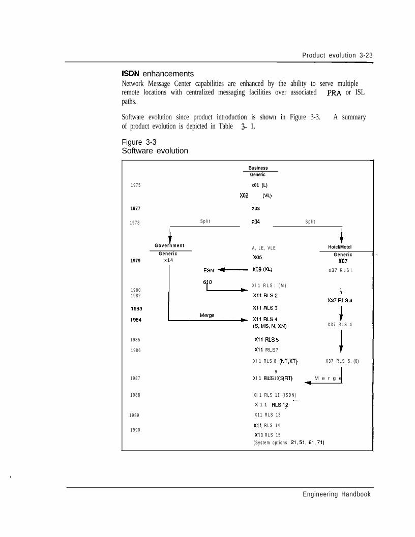
Product evolution 3-23
ISDN enhancementsNetwork Message Center capabilities are enhanced by the ability to serve multipleremote locations with centralized messaging facilities over associated PRA or ISLpaths.
Software evolution since product introduction is shown in Figure 3-3. A summaryof product evolution is depicted in Table 3- 1.
Figure 3-3Software evolution
BusinessGeneric
1 9 7 5 x01 (L)
x02 (VL)
1977
1 9 7 8I
S p l i t
x03
x04 S p l i t
I
tGovernment
Generic1979 x 1 4
A , L E , V L E
x05
+Hotel/Motel
Genericx07
ESN -XOQ (XL) x37 R L S 1
1 9 8 0 6LX l 1 R L S 1 ( M )
11 9 8 2
IX 3 7 R L S 4
1 9 8 5
1 9 8 6
1 9 8 7
1 9 8 8
1 9 8 9
1 9 9 0
X11 RLS5
X11 RLS7
X l 1 R L S 8 (NT,XT) X 3 7 R L S 5 , (6 )
X l 1 RLS (ST)9
X l 1 R L S 1 0 (RT) 1-= M e r g e
X l 1 R L S 1 1 ( I S D N )
X 1 1 RLSl?’ -
X 1 1 R L S 1 3
X11 R L S 1 4
X11 R L S 1 5( S y s t e m o p t i o n s 21,51, 61,71)
I
Engineering Handbook
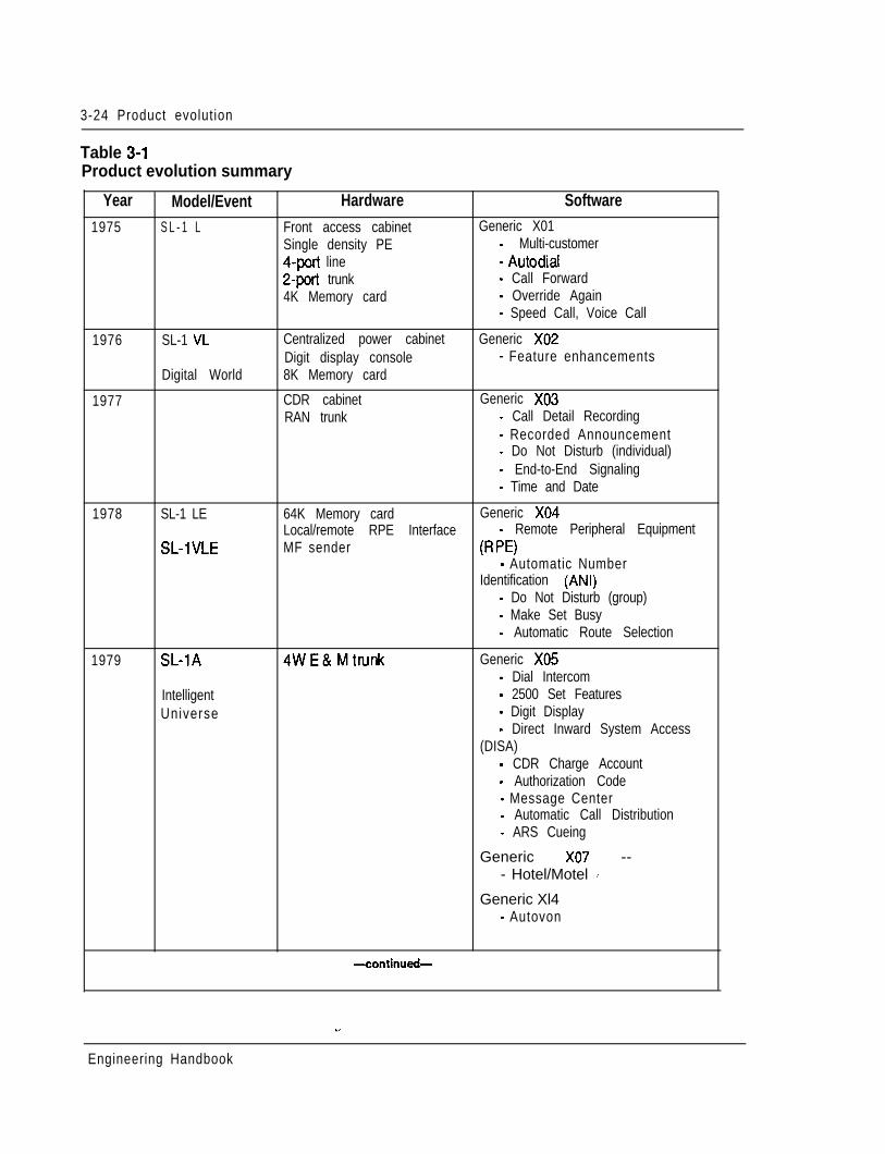
3-24 Product evolution
Table 3-lProduct evolution summary
Year Model/Event Hardware Software1975 S L - 1 L Front access cabinet Generic X01
Single density PE - Multi-customer4-port line - Autodial2-port trunk - Call Forward4K Memory card - Override Again
- Speed Call, Voice Call
1976
1977
SL-1 VL
Digital World
Centralized power cabinetDigit display console8K Memory card
CDR cabinetRAN trunk
Generic X02- Feature enhancements
Generic X03- Call Detail Recording- Recorded Announcement- Do Not Disturb (individual)- End-to-End Signaling- Time and Date
1978 SL-1 LE
SL-1VLE
64K Memory card Generic X04Local/remote RPE Interface - Remote Peripheral EquipmentMF sender (R W
- Automatic NumberIdentification (ANI)
- Do Not Disturb (group)- Make Set Busy- Automatic Route Selection
1979 SL-1A
IntelligentUniverse
4WE&Mtmnk Generic X05- Dial Intercom- 2500 Set Features- Digit Display- Direct Inward System Access
(DISA)- CDR Charge Account- Authorization Code- Message Center- Automatic Call Distribution- ARS Cueing
Generic X07 --- Hotel/Motel d
Generic Xl4- Autovon
-continud-
Engineering Handbook
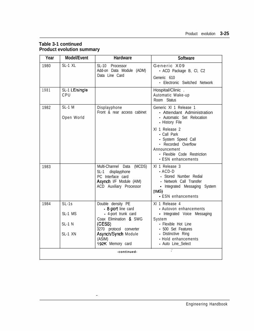
Product evolution 3-25
Table 3-1 continuedProduct evolution summary
Year
1980
Model/Event Hardware SoftwareSL-1 XL SL-10 Processor G e n e r i c X 0 9
Add-on Data Module (ADM) - ACD Package B, Cl, C2Data Line Card Generic 610
- Electronic Switched Network
1 9 8 1 SL-1 LUsingleCPU
Hospital/Clinic .Automatic Wake-upRoom Status
1982 SL-1 M
Open World
Displayphone Generic Xl 1 Release 1Front & rear access cabinet - Attendant Administration
- Automatic Set Relocation- History File
Xl 1 Release 2- Call Park- System Speed Call- Recorded Overflow
Announcement- Flexible Code Restriction- ESN enhancements
1983 Multi-Channel Data (MCDS) Xl 1 Release 3SL-1 displayphone - ACD-DPC Interface card - Stored Number RedialAsynch I/F Module (AIM) - Network Call TransferACD Auxiliary Processor - Integrated Messaging System
WW- ESN enhancements
1984 SL-1s
SL-1 MS
SL-1 N
SL-1 XN
Double density PE- 8-port line card- 4-port trunk card
Coax Elimination & SWG(CE=?3270 protocol converterAsynch/Synch Module(ASIM)192K Memory card
-continued-
Xl 1 Release 4- Autovon enhancements- Integrated Voice Messaging
System- Flexible Hot Line- 500 Set Features- Distinctive Ring- Hold enhancements- Auto Line Select- -
,’
Engineering Handbook
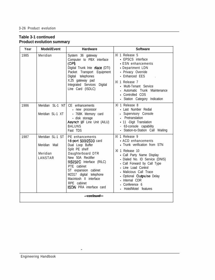
3-26 Product evolution
Table 3-1 continuedProduct evolution summary
Year Model/Event Hardware Software
1985 Meridian System 36 gateway Xl 1 Release 5Computer to PBX interface - EPSCS interface1w - ESN enhancementsDigital Trunk lnte rtace (DTI) - Department LDNPacket Transport Equipment - Privacy OverrideDigital telephones - Enhanced EES .X.25 gateway padIntegrated Services Digital
Xl 1 Release 7
Line Card (ISDLC)- Multi-Tenant Service- Automatic Trunk Maintenance- Controlled COS- Station Category Indication
1986 Meridian SL-1 NT CE enhancements Xl 1 Release 8- new processor - Last Number Redial
Meridian SL-1 XT - 768K Memory card - Supervisory Console- disk storage - Pretranslation
Asynch I/F Line Unit (AILU) - 11 -Digit TranslationBALUNS - 63-console capabilityFast TDS - Station-to-Station Call Waiting
1987 Meridian SL-1 ST PE enhancements Xl 1 Release 916-port 500/2500 card - ACD enhancements
Meridian Mail Dual Loop Buffer - Trunk verification from STNSplit PE shelf
Meridian Daughterboard DTRXl 1 Release 10
LANSTAR New 50A Rectifier- Call Party Name Display
RS232C Interface (RILC)- Dialed No. ID Service (DNIS)
PTE cabinet- Call Forward by Call Type
ST expansion cabinet- Line Load Control
M2317 digital telephone- Malicious Call Trace
Macintosh II interface- Optional Outpulse Delay
RPE cabinet- Internal CDR
ISDN PRA interface card- Conference 6- Hotel/Motel features
-continued-
Engineering Handbook
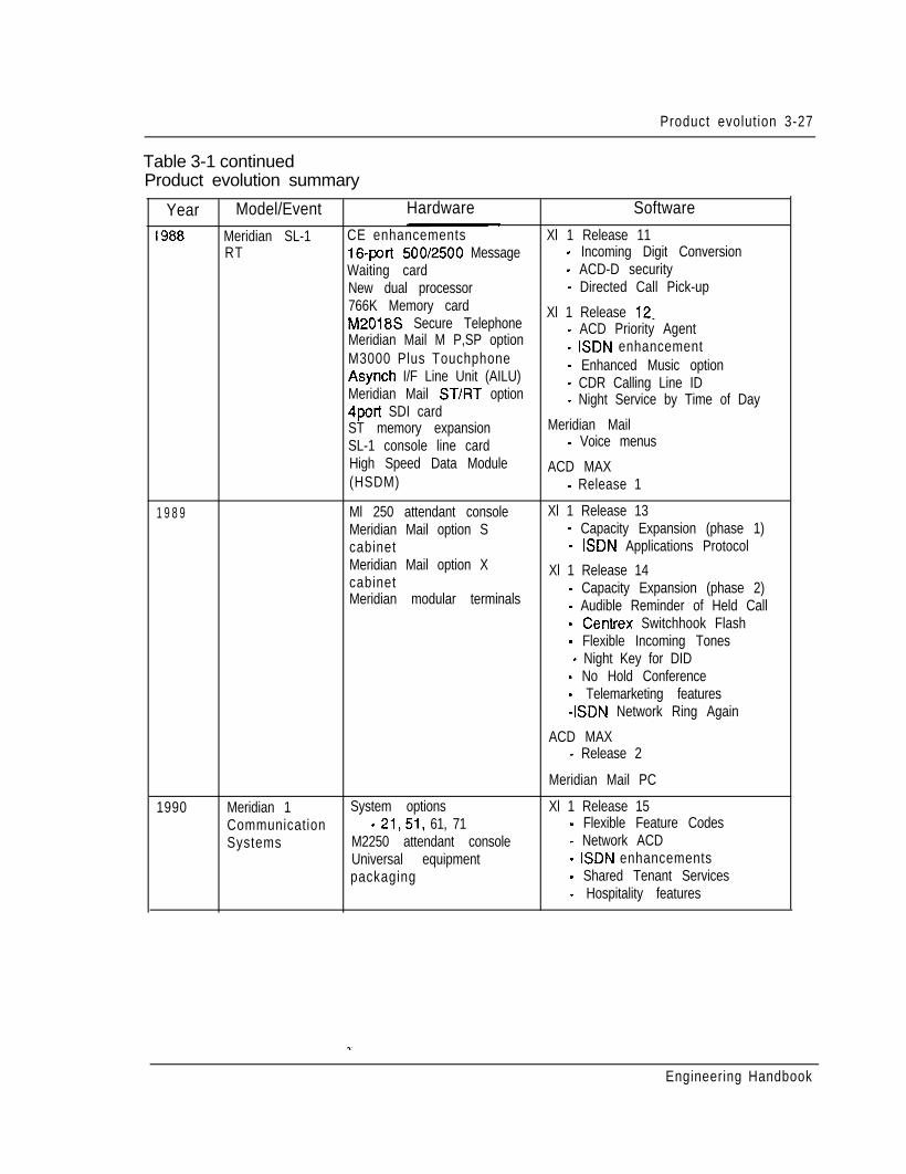
Product evolution 3-27
Table 3-1 continuedProduct evolution summary
Year Model/Event Hardware Software
I988 Meridian SL-1 CE enhancements Xl 1 Release 11RT 16-port 500/2500 Message - Incoming Digit Conversion
Waiting card - ACD-D securityNew dual processor - Directed Call Pick-up766K Memory cardM2018S Secure Telephone
Xl 1 Release 12_
Meridian Mail M P,SP option- ACD Priority Agent
M3000 Plus Touchphone- ISDN enhancement
Asynch I/F Line Unit (AILU)- Enhanced Music option
Meridian Mail ST/FIT option- CDR Calling Line ID
4port SDI card- Night Service by Time of Day
ST memory expansion Meridian MailSL-1 console line card - Voice menusHigh Speed Data Module ACD MAX(HSDM) - Release 1
1 9 8 9 Ml 250 attendant console Xl 1 Release 13Meridian Mail option S - Capacity Expansion (phase 1)cabinet - ISDN Applications ProtocolMeridian Mail option Xcabinet
Xl 1 Release 14
Meridian modular terminals- Capacity Expansion (phase 2)- Audible Reminder of Held Call- Centrex Switchhook Flash- Flexible Incoming Tones
- Night Key for DID- No Hold Conference- Telemarketing features-ISDN Network Ring Again
ACD MAX- Release 2
Meridian Mail PC
1990 Meridian 1 System options Xl 1 Release 15Communication - 21,51, 61, 71 - Flexible Feature CodesSystems M2250 attendant console - Network ACD
Universal equipment - ISDN enhancementspackaging - Shared Tenant Services
- Hospitality features
Engineering Handbook

4-1
Chapter 4: System architecture
ContentsMeridian 1 modular architecture
ControlSwitchingPeripherals
Software architectureFirmwareSoftwareOffice dataResident programsNon-resident programs
Service change and print routinesMaintenance diagnosticsTrafficEquipment data dumpSoftware audit
Hardware architectureCommon equipment
Central Processing Unit (CPU)Mass Storage UnitInput / Output (l/O) interfacesMemory
Unprotected Data Store (UDS)Protected Data Store (PDS)Program Store (PS)
Network equipmentLoops and SuperloopsNetwork organization
Peripheral equipmentPCMRemote Peripheral Equipment (RPE)DTVPR INetwork/peripheral configuration
Enhanced network configurationsSuperloop network configurationsOne segment per superloop
4-24-24-24-24-34-34-34-34-44-44-44-44-54-54-54-64-64-64-74-74-84-84-84-84-94-94-9
4-104-104-114-114-114-134-154-17
Engineering Handbook
4-2 System Architecture
Two segments per superloop 4-18Four segments per superloop 4-19Eight segments per superloop 4-20One segment per superloop/three segments per superloop 4-22Two segments per superloop/six segment5 per superloop 4 - 2 3
Power equipment 4 - 2 5
Meridian 1 modular architectureAn important characteristic of Meridian 1 systems is a modular system architecture.It utilizes an efficient and flexible approach, employing modular construction in allareas of hardware and software, and state-of-the-art commercial and customcomponents. The result is a system which is highly flexible in terms of operational,maintenance, and administrative characteristics. As demands dictate, any modulemay be enhanced, singularly or in combination with other modules. Each system isorganized around three functional areas: Control, Switching, and Peripherals.
ControlThe Control complex provides the sequences required by the system to processvoice and data call connections, monitor call activity, and perform systemadministration, maintenance, and testing. It is composed of two elements: theCentral Processing Unit (CPU) which directs lower level subsystems in thehierarchy, and the system memory which stores the operating programs.
SwitchingThe switching function is performed by the network equipment, whichinterconnects terminal devices for communication with each other. The networkarchitecture is based on the concept of a digital multiplexed loop. A loop is abidirectional path between Network and terminal device which transmits voice, dataand signalling information.
PeripheralsPeripheral equipment provides the analog and digital interfaces for all peripheraldevices, and performs analog to digital conversion of all input signals beforeswitching is performed by the Network. Additionally, peripheral equipment circuitsprovide the supervisory and transmission functions needed for trunks connected tothe external telecommunications network.
Meridian 1 systems use a star topology for connecting peripheral devices to theswitching equipment, an approach which permits uniform distributed wiringmethods. This approach provides significant benefits in the area of administration,installation, maintenance, and reliability.
Engineering Handbook
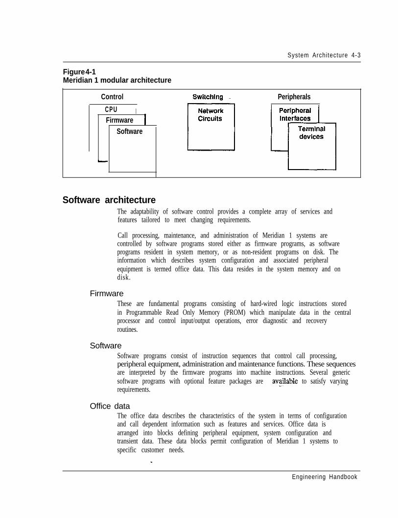
System Architecture 4-3
Figure 4-1Meridian 1 modular architecture
Control
CPU IFirmware
Software
-
Peripherals,
Software architectureThe adaptability of software control provides a complete array of services andfeatures tailored to meet changing requirements.
Call processing, maintenance, and administration of Meridian 1 systems arecontrolled by software programs stored either as firmware programs, as softwareprograms resident in system memory, or as non-resident programs on disk. Theinformation which describes system configuration and associated peripheralequipment is termed office data. This data resides in the system memory and ondisk.
FirmwareThese are fundamental programs consisting of hard-wired logic instructions storedin Programmable Read Only Memory (PROM) which manipulate data in the centralprocessor and control input/output operations, error diagnostic and recoveryroutines.
SoftwareSoftware programs consist of instruction sequences that control call processing,peripheral equipment, administration and maintenance functions. These sequencesare interpreted by the firmware programs into machine instructions. Several genericsoftware programs with optional feature packages are ava.lable to satisfy varyingrequirements.
Office dataThe office data describes the characteristics of the system in terms of configurationand call dependent information such as features and services. Office data isarranged into blocks defining peripheral equipment, system configuration andtransient data. These data blocks permit configuration of Meridian 1 systems tospecific customer needs.
Engineering Handbook
4-4 System Architecture
Resident programsResident programs are programs always available in memory during systemoperation. Firmware programs control other resident programs and provide all CPUarithmetic operations. The other resident programs are those which areautomatically loaded into the system memory from the disk drive at system power-up. Once loaded, these programs remain in memory.
Non-resident programsNon-resident programs are the overlay programs stored on disk which are loadedinto the “overlay area” of system memory when required to perform specific tasks.Only one overlay program may be loaded at a time and is removed from the overlayarea when no longer required. Overlay programs can be loaded automatically,under program control, or manually, via an administrative terminal.
Once the user has logged into the system, commands for specific overlay programsare processed by the overlay loader program. When loaded, the overlay programassumes control. Only one administrative terminal can input into the overlay area ata time. More than one device, however, can receive output simultaneously. Aterminal may be configured as an input only or output only device.
Overlay programs provide the system interface for maintenance, service change,and traffic measurement. Each overlay program is independent and has its ownspecific set of commands and formats. Overlay programs may be run concurrentlywith normal call processing without interfering with system traflic. There are fivemain categories of overlay programs:- Service change and print routines- Maintenance diagnostics- Traffic- Equipment data dump- Software audit
Service change and print routinesService changes do not generally require hardware intervention. Instead, the serviceadministration programs are used to create or modify all aspects of the system fromindividual feature key assignments to complete system configurations. There arealso programs and print routines for retrieving the data from the system to check thestatus of office data assignments. _-
Maintenance diagnosticsThese programs are the primary instruments for maintenance purposes. Individualprograms are used for automatically or manually testing the Common Equipment(CE) and Peripheral Equipment (PE). The programs may be loaded into the overlayarea at the request of maintenance personnel, or as part of a daily maintenanceroutine automatically initiated by the system at a specified time. In addition,
Engineering Handbook
System Architecture 4-5
background and signaling diagnostic routines can occupy the overlay area when it isnot in use.
TrafficAll systems are equipped with traffic data accumulation programs. There is also aresident traffic print program which examines the schedules, transfers data fromaccumulating to holding registers in accordance with schedules, and prints thetraffic data. In addition, there is a traffic overlay program which is used to queryand modify schedules, options, and thresholds.
Equipment data dumpAfter making service changes, the changes must be transferred to disk in order tosave them. When the equipment data dump program is invoked, all the office datain the read/write memory is written to the system disk. The data dump program isalso used to install a new generic version or issue and capture protected data storeinformation which may be changed by the user, such as speed call lists. Theprogram may be invoked automatically during a midnight routine or on aconditional basis (i.e., data dump only occurs if a software service change has beenmade). It may also be invoked manually via the input/output (I/O) interface to thesystem.
Software auditThis program monitors system operation and gives an indication of the general stateof the system operation. The program is concerned mainly with the systemsoftware. When a software problem is encountered, the program attempts to clearthe problem automatically.
Engineering Handbook
4-6 System Architecture
Hardware architectureEach Meridian 1 system is composed of the following hardware subsystems:- Common equipment (CE) - provides the device control, software execution,
and memory functions of the system- Network equipment (NET) - performs the switching function under CPU
control- Peripheral equipment (PE) - provides the interface for line and trunk circuits- Terminal equipment - telephone sets and attendant consoles- Power equipment - provides the electrical voltages required to operate
equipment
Common equipmentCommon Equipment (CE) consists of one or mere Central Processing Units(CPUs), memory circuits, and mass storage devices which control the operation ofthe system. The CE communicates over a common control bus which carries aconstant flow of program instructions and data under direct control of the CPU. Thedigitized speech signals follow a separate path on a network switching bus whichallows communications links to be established between any of the peripheraldevices.
The Central Processing Unit (CPU) provides the computing power essential for theentire system operation. The system memory stores all operating software programsand data unique to a particular Meridian 1 system, including switching sequences,features, class of service information, and quantity and types of terminals. TheMass Storage Unit provides high speed loading of the operating programs and datainto memory. The digital service circuits provide functions such as dial and ringingtones, and call conferencing capabilities. The Serial Data Interface (SDI) providesan RS232C communications link for administration and maintenance on either alocal or remote basis. The network circuit cards provide a digital matrix for circuit-switched connections to associated peripheral devices.
Central Processing Unit (CPU)The CPU performs the control and switching sequences required by the system. Thesoftware that directs these functions is loaded into the system memory from themass storage unit by the CPU. Information flows between the CPU, I/O devices,and the system memory over the CPU bus. _-The data required by the CPU to perform its control and switching functions is heldduring system operation in Random Access Memory (RAM) and fed to the CPU viathe CPU bus. The operating data is loaded into the RAM from floppy diskettes onsystem power-up.
The CPU function is performed by circuit cards which include Read-Only-Memoryfirmware that contains fault clearing programs and instructions to control theloading of system memory from the mass storage unit.
Engineering Handbook
System Architecture 4-7
Meridian 1 system options 5 1,6 1, and 71 incorporate the following CPU design:- 24-bit data words plus l-bit parity- 24-bit linear addressing that permits memory allocation to be assigned on a
contiguous basis- 16M words - subdivided for up to 12M words of physical memory space and a
remainder of 4M words for I/O spaces- asynchronous (handshake) bus operation
16 file registers used to hold address and data for all operations-- a sense (interrupt) input line to indicate that a particular device (tape, TTY, PE,
etc.) requires action by the CPU- a trap facility which, when activated by an external signal, causes the CPU to
immediately begin executing instructions starting at a particular address; thisfacility is used to enter a recovery routine when a fault is detected.
Meridian 1 system option 21 uses a 16-bit processor for small sized businessapplications.
Mass Storage UnitA Floppy Disk Unit (FDU) equipped with two 3.5~inch disks and a Multi-Disk Unit(MDU) with additional hard disk is used for high speed loading of the residentoperating programs and office data into system memory. The loading process iscontrolled by instructions held in the Read-Only-Memory (ROM) firmware. Whenloading is complete, the diskettes remain in the mass storage unit to provide a non-volatile store for automatic loading purposes in the event of software being erasedfrom memory during a power failure. Non-resident software is loaded from the diskautomatically or by manual request when required.
The Mass Storage Interface (MSI) card is designed to interface with externaldevices that are compatible with the Small Computer System Interface (SCSI). Thisstorage capability is provided by the following hardware configurations:- NT8D68AA Floppy Disk Unit - two 3.5” 1.2 Mbyte floppy disk drives
(providing 2.4 Mbytes of formatted capacity) as a standard system offering- NT8D69 AA Multi Disk Unit - a hard disk drive with 20 Mbytes of formatted
capacity. When this option is equipped, the floppy disks are used for backupand system loading.
Input / Output (l/O) interfaces --There are various methods of communicating with Meridian 1 systems. A family ofSerial Data Interface (SDI) circuit cards provides from one to four communicationchannels which conform to EIA Data Interchange Standard RS-232-C. I/Oaddressing is under switch control of the SD1 card and allows up to 16 RS-232-Ccompatible devices, such as terminals, to communicate with the system. Thedevices are used to input commands and/or receive responses from the systemduring administration and maintenance procedures.
Engineering Handbook
4-8 System Architecture
MemoryFirmware, software, and data are stored in a read/write Random Access Memory(RAM). The memory is a critical part of the stored program control system. Itcontains the memory stores of all of the basic operating instructions for the system,plus data on the configuration of the particular application being served. Memoryutilization is dependent upon what features are programmed into the system and thenumber of peripheral terminations being served. The memory is split into foursegments to facilitate processor address purposes and permit a functional separationof programs .
Unprotected Data Store (UDS)These pages hold the transient or unprotected data that is required during callprocessing. Included are the timing queues and call registers.
Protected Data Store (PDS)This protected data store holds the office data blocks that are particular to specificinstallations.
Program Store (PS)Allocations within the Program Store are as follows:
Firmware - This portion of the memory is a non-volatile Read Only Memory(ROM) used for storage of all system firmware. The ROM is programmed duringmanufacture and the instructions are permanent and indestructible. It stores thebasic rules of operation necessary to initialize the system and bring it into a workingstate. A recovery or “trap sequence” is included in firmware which is automaticallyinvoked in response to power-on, system reset, or when certain faults are detected.
Overlay -This portion of the memory may be loaded with various non-residentprograms as required during automatic diagnostics, service order change, trafficmeasurement, or maintenance.
Software - The remainder of this memory page is reserved for all of the systemsoftware such as the call processing and optional programs. Additional softwarestorage capability is provided by the incremental addition of more memory pageswithin this category.
Input / Output addresses - There are no RAM modules utilized for this page.Instead the address range is reserved for Input/Output (I/O) device addresses. Thesedevices include signaling for peripheral equipment along with magnetic tape andterminal assignments.
Engineering Handbook
System Architecture 4-9
Network equipmentNetwork equipment consists of network circuit cards which perform the digitalswitching of voice and data signals, peripheral signalling cards which performscanning and signal distribution, and service circuit cards, such as tone and digitswitches, which provide call progress tones and outpulsing as instructed by theCPU. Network circuits employ Pulse Code Modulation (PCM) and Time DivisionMultiplexing (TDM) to perform the switching function.
Loops and SuperloopsNetwork equipment interfaces with peripheral equipment via digital multiplexedloops. A loop is a bidirectional path between Network equipment (NET) andPeripheral equipment (PE) for voice, data and signalling information. Uponcommands from the CE, the network establishes a path, linking a specific input to aspecific output.
Meridian 1 systems provide two network circuit cards, the QPC414 Network cardwhich provides 2 loops per card, and the NT8DO4AA Super-loop Network cardwhich provides 4 loops per card, grouped together in an entity called a Supcrloop.TheSuperloop permits all 120 timeslots provided by the network card to be sharedamong the peripheral devices served by the superloop, providing higher trafficcapacity and simplified traffic engineering.
The flexibility of the network loop plays an important role in the Meridian 1architecture. Besides the ability to increase circuit-switched bandwidth on anincremental card basis for cost-effective growth, application may be varied for valueadded services. The network structure allows for the full connectivity of all devicesirrespective of how they connect to the system.
The network loop is a key element in the implementation of Primary Rate Access(PRA) and Digital Trunk Interface (DTI). The PRA offers twenty-three 64-KbpsB channels and one D channel; it connects PBXs to ISDN nodes (such asinterexchange carriers, local exchange carriers) or private network facilities (such asPBXs or host computers). The DTI provides a digital link of 24 channels each ofwhich may be flexibly allocated for both voice and data communications. The DTIuses the North American T- 1 standard (DS- 1 format); each equipped link isassigned an associated network loop.
Network organization -Network loops are organized into groups. Systems are configured as half, full, ormultiple group machines. A half network group machine provides up to 16 loops, afull group system provides up to 32 loops, while a multiple group system providesup to 160 loops.
Engineering Handbook
4-10 System Architecture
For applications beyond the traffic handling capability of the single network group,additional switching stages are introduced to form a multi-group arrangement.These connecting paths, provided by the InterGroup Module, are merely anextension of the originating and terminating network loop involved in a call. Thereare eight one way junctors from each group to all others. Since each path providesthirty connecting channels, a total of 480 connection paths exist from one group toanother, 240 in each direction. Five network groups may be interconnected toconstitute a fully configured digital switching matrix.
Peripheral equipmentPeripheral Equipment (PE) consists of peripheral controller cards which provide thetiming and control sequences for peripheral circuits, analog and digital line andtrunk cards, which provide the interfaces for terminal devices, and circuit cardswhich provide Digital Trunk Interface (DTI) and Primary Rate Access (PRA)services.
The peripheral controller performs the first stage of multiplexing signals from theterminals, which are then passed on to the network for digital switching. Theperipheral controller also transmits timing signals, and carries out other functionsassociated with the control of the peripheral circuits.
The analog line card converts incoming analog signals into digital signals which arethen passed on to the peripheral controller. This conversion is accomplished by anintegrated encoder/decoder (codec) chip. There is a codec for each port on the linecard. Conversion from digital back to analog is also performed by the codec foroutgoing signals. For digital telephones, the codec is located within the telephoneset itself.
PCMPulse Code Modulation (PCM) is used to convert analog signals to digital signals.The PCM method converts the analog signal to digital by sampling the amplitude ofthe analog signal at a rate of twice the highest signal frequency and converting theamplitude of each sample into a series of coded pulses. The PCM samplingfrequency standard for telecommunications is 8 KHz.
Companding (compressing - expanding) PCM is a standard technique for using8-bit words to efficiently represent the wide dynamic range of voice and datasignals. Two standards for companding am internationally recognized:_-- Mu-255 law for North American applications- A-law for international service
Meridian 1 codecs conform to both standards and are software selectable (inIntelligent Peripheral Equipment Modules) for use in North America andinternationally. The codecs are also designed to pass signals up to 3.4 KHz withminimum time delay and low phase distortion, a requirement for the propertransmission of data signals.
Engineering Handbook
System Architecture 4-11
Remote Peripheral Equipment (RPE)In a local operating environment, the peripheral equipment may be housed up to15.2 m (50 ft) from the common equipment. The RPE feature extends this range tcapproximately 112.6 km (70 miles) between local and remote facilities. Thisextension is made possible by converting the multiplexed loop signals to a formcompatible with the commonly used T-l type digital transmission system.
Any medium conforming to DS- 1 format (1.544 Mbps) may be used to link localand remote sites, including digital microwave radio and fiber optic transmissionsystems.
DTVPRIAllocation of circuit-switched bandwidth may also be made on a network loop basisto Primary Rate Access (PRA) or Digital Trunk Interface (DTI) circuits. Theseoptional services are based on the standard T-l format (DS-1 24 channel) used indigital transmission networks.
The PRA offers twenty-three 64-Kbps B channels and one D channel; it connectsPBXs to ISDN nodes (such as interexchange carriers, local exchange carriers) orprivate network facilities (such as PBXs or host computers)
The DTI allows for the replacement of 24 conventional analog trunks by a single T-1 digital link. Each of 24 channels provides up to 56 Kbps for voice andsynchronous data transmission, or up to 19.2 Kbps for asynchronous data.
Network/peripheral configurationThe allocation of peripheral equipment to the network loop determines the traffichandling capability of the switching network. The lower the number ofterminations, the higher the loop traffic capacity. The quantity and type of terminalassignments are allocated to optimize the traffic handling capabilities of theswitching network.
A universal PE bus structure permits any mix of PE card types to be located in a PEmodule. Provisioning of PE cards and their associated density (number of ports)determines the network loop to PE module configuration. Complete modularitypermits voice and data modules to be segregated so that the specific traffic patternsof one may be met without impeding the other.
Figure 4-2 shows the arrangement between the network %td peripheral equipment.
Engineering Handbook
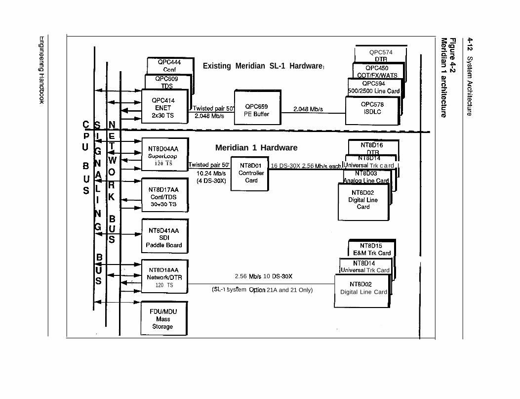
IExisting Meridian SL-1 Hardware
I QPC574 1
Meridian 1 Hardware
120 IS Twisted Pair 50’1 NT8DOl 1 16 DS-30X 2.56 Mb/s nnch IUniversal Trk card I 1
I NT8D14 II INT8D18AA
NetworWDTR120 TS
2.56 Mb/s 10 DS30X
,^. 1 ^- )tion 21A and 21 Only)(x-1 system 0~
IUniversal Trk Card
NT8D02Digital Line Card _
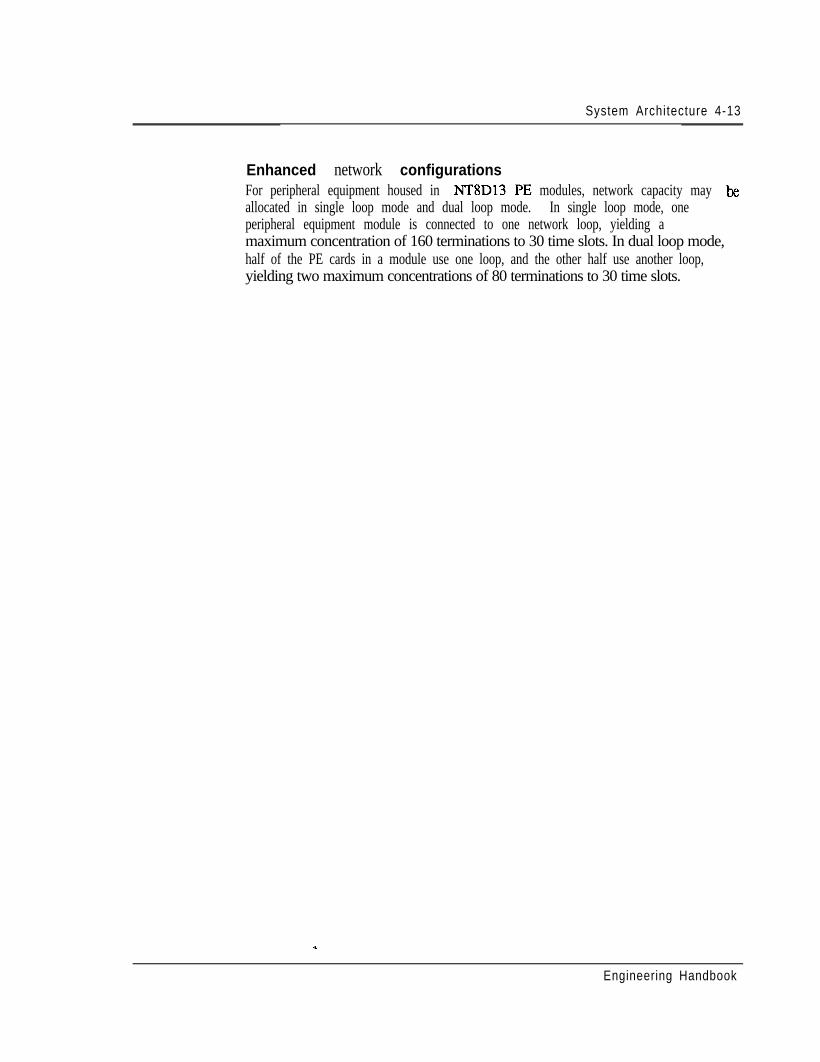
System Architecture 4-13
Enhanced network configurationsFor peripheral equipment housed in NT8D13 PE modules, network capacity may Ixallocated in single loop mode and dual loop mode. In single loop mode, oneperipheral equipment module is connected to one network loop, yielding amaximum concentration of 160 terminations to 30 time slots. In dual loop mode,half of the PE cards in a module use one loop, and the other half use another loop,yielding two maximum concentrations of 80 terminations to 30 time slots.
w
Engineering Handbook
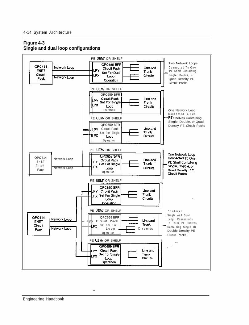
4-14 System Architecture
Figure 4-3Single and dual loop configurations
PE UEfvl/ OR SHELFI L
LOOP
Two Network LoopsC o n n e c t e d T o O n e
_ P E S h e l f C o n t a i n i n gS i n g l e , D o u b l e , o rQuad Density PECircuit Packs
PE UEW OR SHELF
rr QPC659 BFR 1
O p e r a t i o n
PE UEMl OR SHELF
QPC659 BFR- _ LPy Circuit Pack
-‘LPxS e t F o r S i n g l eLwp
O p e r a t i o n
One Network LoopC o n n e c t e d T o T w o
-PE Shelves ContainingSingle, Double, or QuadDensity PE Circuit Packs
,QPC414
E N E TC i r c u i tPack
I I P E UEM/ OR SHELF -
rm mr-Network Loop
Network Loop
QPCGOY orn
O p e r a t i o n
PE UEMl OR SHELF
PE UEM/ OR SHELF
QPC659 BFR-- Lpy Ci rcu i t Pack_ _ Lpx S e t F o r D u a l
L o o p _Ez_ C i r c u i t sO p e r a t i o n
I PE UEMI OR SHELF I
C o m b i n e dS i n g l e A n d D u a lL o o p C o n n e c t i o n sT o T h r e e P E S h e l v e s-C o n t a i n i n g S i n g l e O rDouble Density PECircuit Packs
Engineering Handbook
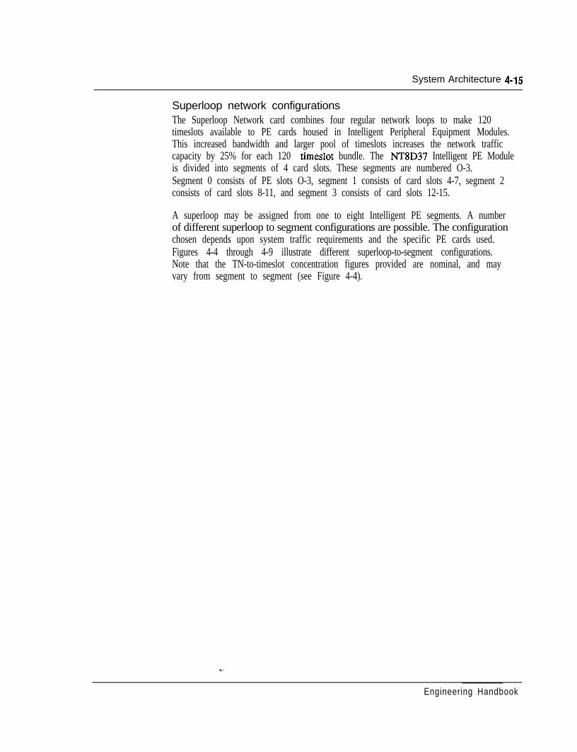
System Architecture 4-15
Superloop network configurationsThe Superloop Network card combines four regular network loops to make 120timeslots available to PE cards housed in Intelligent Peripheral Equipment Modules.This increased bandwidth and larger pool of timeslots increases the network trafficcapacity by 25% for each 120 timeslot bundle. The NT8D37 Intelligent PE Moduleis divided into segments of 4 card slots. These segments are numbered O-3.Segment 0 consists of PE slots O-3, segment 1 consists of card slots 4-7, segment 2consists of card slots 8-11, and segment 3 consists of card slots 12-15.
A superloop may be assigned from one to eight Intelligent PE segments. A numberof different superloop to segment configurations are possible. The configurationchosen depends upon system traffic requirements and the specific PE cards used.Figures 4-4 through 4-9 illustrate different superloop-to-segment configurations.Note that the TN-to-timeslot concentration figures provided are nominal, and mayvary from segment to segment (see Figure 4-4).
Engineering Handbook
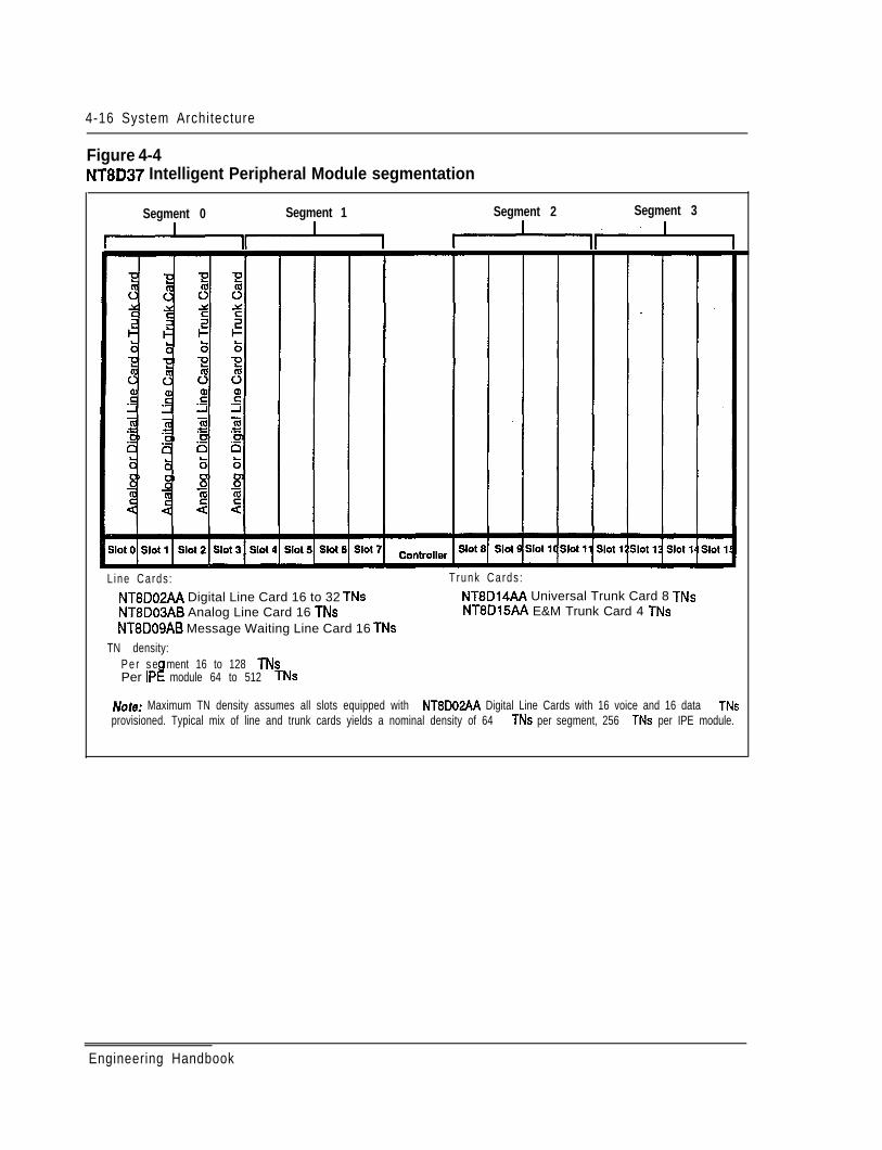
4-16 System Architecture
Figure 4-4NT8D37 Intelligent Peripheral Module segmentation
Segment 0 Segment 1 Segment 2 Segment 3
+* **
L ine Cards : T runk Cards :NT8D02AA Digital Line Card 16 to 32 TNs NTBD14AA Universal Trunk Card 8 TNsNT8D03AB Analog Line Card 16 TNs NT8D15AA E&M Trunk Card 4 TNsNT8DOSAB Message Waiting Line Card 16 TNs
TN density:P e r s e ment 16 to 128 TNsPer IPI! module 64 to 512 TNs
Elate: Maximum TN density assumes all slots equipped with NT8D02AA Digital Line Cards with 16 voice and 16 data TNsprovisioned. Typical mix of line and trunk cards yields a nominal density of 64 TNs per segment, 256 TNs per IPE module.
Engineering Handbook
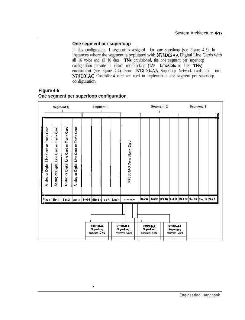
System Architecture 4-17
One segment per superloopIn this configuration, 1 segment is assigned to one superloop (see Figure 4-5). Ininstances where the segment is populated with NT8DO2AA Digital Line Cards withall 16 voice and all 16 data TNs provisioned, the one segment per superloopconfiguration provides a virtual non-blocking (120 timeslots to 128 TNs)environment (see Figure 4-4). Four NT8DO4AA Superloop Network cards and oneNT8DOlAC Controller-4 card are used to implement a one segment per superloopconfiguration.
Figure 4-5One segment per superloop configuration
Segment 0I
Segment 1 Segment 2 Segment 3
I II
II
‘lot 0 Slot1 Slot2 Slot 3 Slot4 Slo15 S l o t 6 Slot7 controller ISM1 slot9 slot10 slot11 slot 12 slot13 slot 14 slot1
I
NTBDWAA
SW=~OPNetwork Card
NTBLXMAA%=kJOP
Network Card
I
NT8DO4AASW=~P
Network Card
N-iXDlMAP.superloop
Network Card
- -
Engineering Handbook
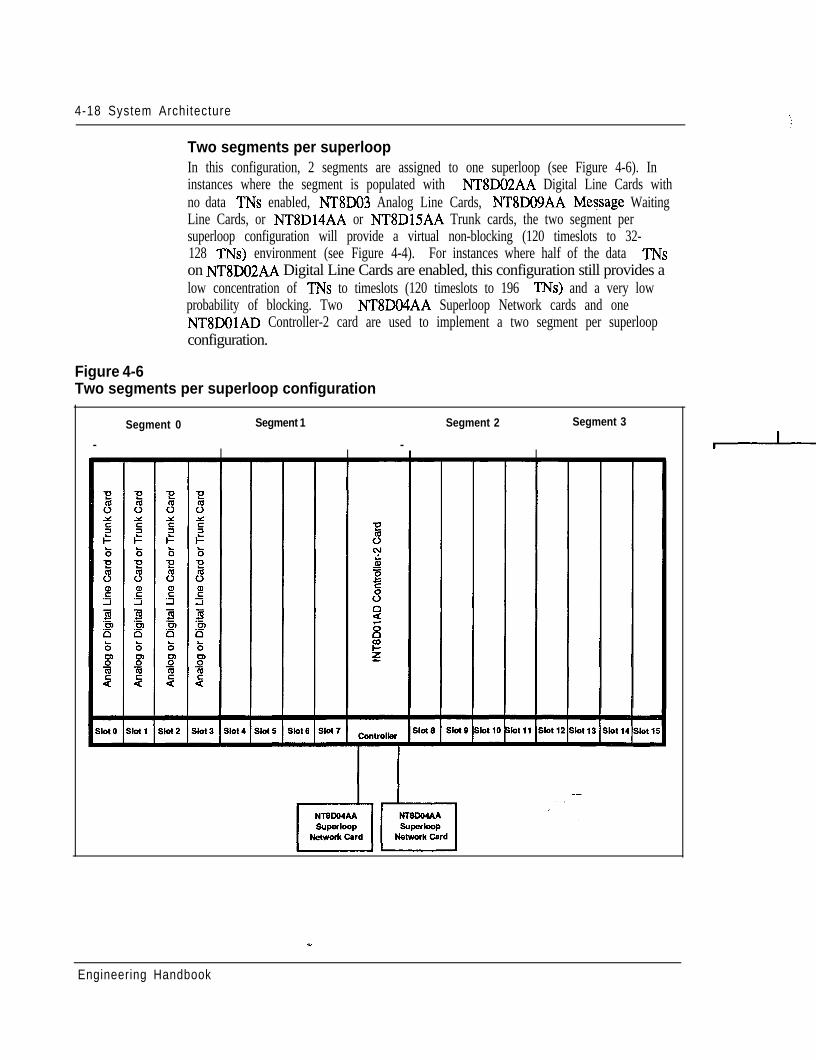
4-18 System Architecture
Two segments per superloopIn this configuration, 2 segments are assigned to one superloop (see Figure 4-6). Ininstances where the segment is populated with NT8DO2AA Digital Line Cards withno data TNs enabled, NT8DO3 Analog Line Cards, NTSDO9AA MeSsage WaitingLine Cards, or NT8D14AA or NT8DlSAA Trunk cards, the two segment persuperloop configuration will provide a virtual non-blocking (120 timeslots to 32-128 TNs) environment (see Figure 4-4). For instances where half of the data TNson NT8DO2AA Digital Line Cards are enabled, this configuration still provides alow concentration of TNs to timeslots (120 timeslots to 196 TNs) and a very lowprobability of blocking. Two NT8DO4AA Superloop Network cards and oneNT8DOlAD Controller-2 card are used to implement a two segment per superloopconfiguration.
Figure 4-6Two segments per superloop configuration
Segment 0 Segment 1 Segment 2 Segment 3
- - II
Engineering Handbook
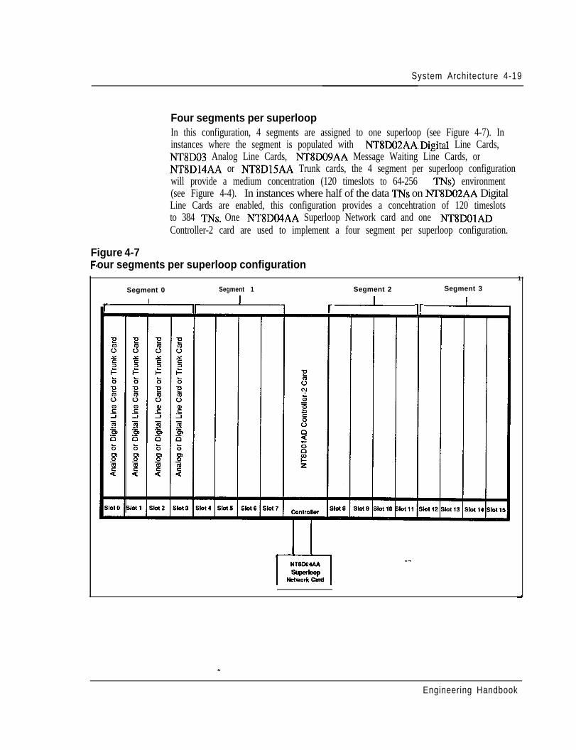
System Architecture 4-19
Four segments per superloopIn this configuration, 4 segments are assigned to one superloop (see Figure 4-7). Ininstances where the segment is populated with NT8DO2AA.Digital Line Cards,NT8DO3 Analog Line Cards, NT8DO9AA Message Waiting Line Cards, orNT8D14AA or NTSDlSAA Trunk cards, the 4 segment per superloop configurationwill provide a medium concentration (120 timeslots to 64-256 TNs) environment(see Figure 4-4). In instances where half of the data TNs on NT8D02AA DigitalLine Cards are enabled, this configuration provides a concehtration of 120 timeslotsto 384 TNs. One NTSDO4AA Superloop Network card and one NT8DOlADController-2 card are used to implement a four segment per superloop configuration.
Figure 4-7Fl our segments per superloop configuration
1
Segment 1 Segment 2 Segment 3Segment 0
Ir ir vr
NrolmIAAr-lSuperloOP
t&Work Card
Engineering Handbook
4-20 System Architecture
Eight segments per superloopIn this configuration, 8 segments are assigned to one superloop (see Figure 4-8). Ininstances where the segment is populated with NT8DO2AA Digital Line Cards,NT8DO3 Analog Line Cards, NTSDO9AA Message Waiting Line Cards, orNT8D14AA or NT8DlSAA Trunk cards, the 8 segment per superloop configurationwill provide a high concentration (120 timeslots to 128-512 TNs) environment (seeFigure 4-4). In instances where half of the data TNs on NTSDO%AA Digital LineCards are enabled, this configuration provides a concentration of 120 timeslots to768 TNs. One NT8DO4AA Superloop Network card and two NTSDOlADController-2 cards are used to implement an eight segment per superloopconfiguration.
Engineering Handbook
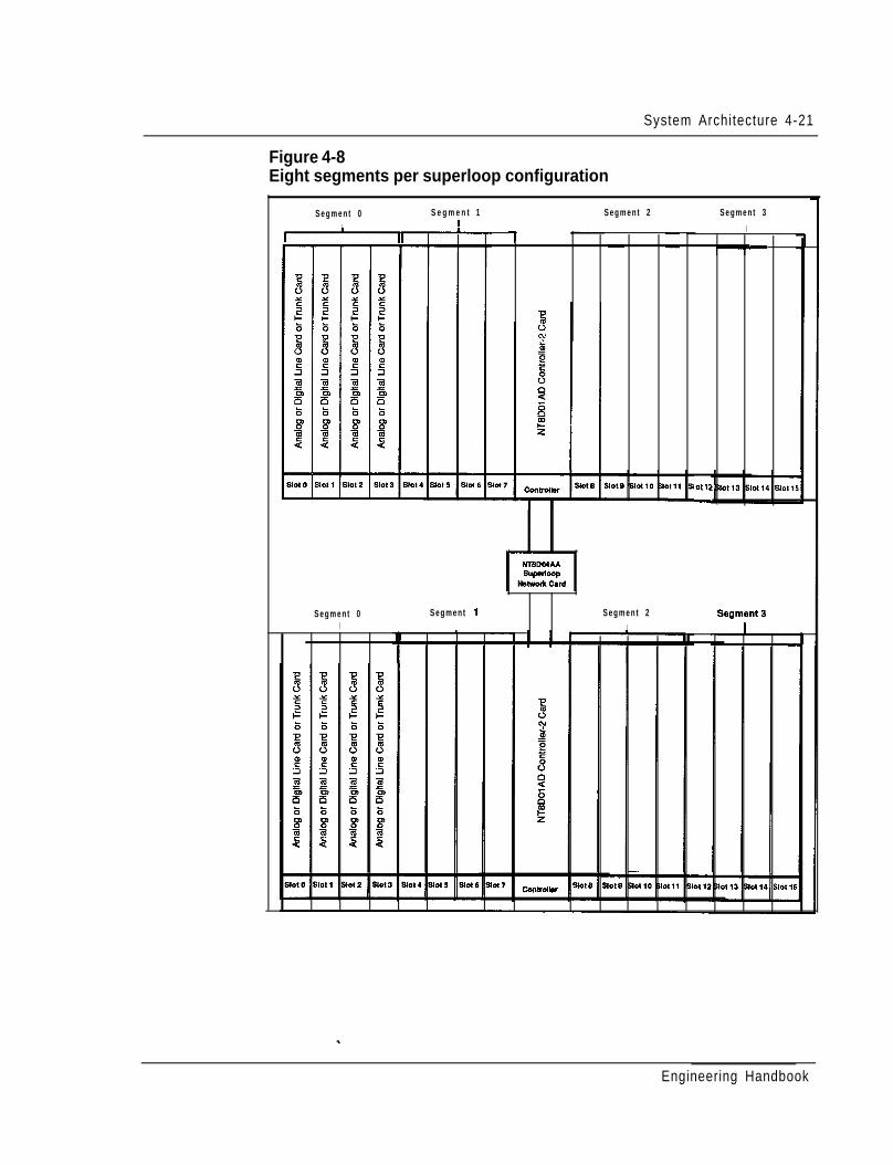
System Architecture 4-21
Figure 4-8Eight segments per superloop configuration
S e g m e n t 1t
S e g m e n t 2 S e g m e n t 3
I
-
otli
-
S e g m e n t 0I
1-
S e g m e n t 1S e g m e n t 0I
S e g m e n t 2
I
Engineering Handbook
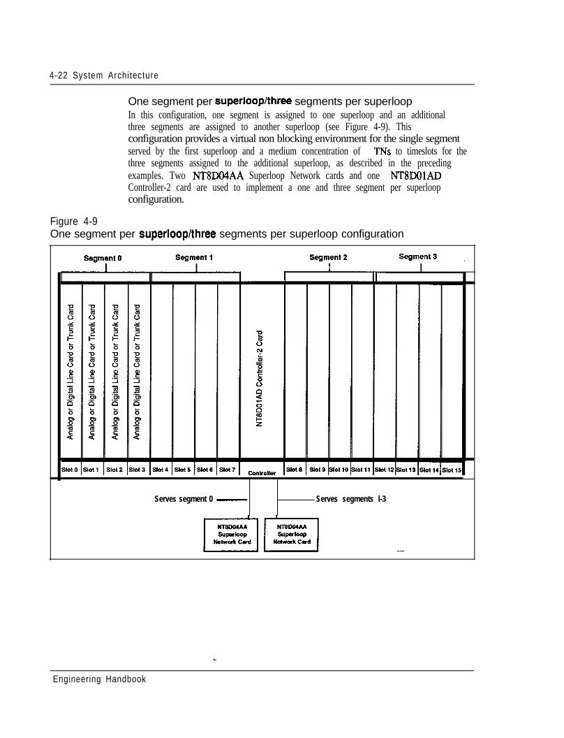
4-22 System Architecture
One segment per superlooplthree segments per superloopIn this configuration, one segment is assigned to one superloop and an additionalthree segments are assigned to another superloop (see Figure 4-9). Thisconfiguration provides a virtual non blocking environment for the single segmentserved by the first superloop and a medium concentration of TNs to timeslots for thethree segments assigned to the additional superloop, as described in the precedingexamples. Two NTUXMAA Superloop Network cards and one NT8DOlADController-2 card are used to implement a one and three segment per superloopconfiguration.
Figure 4-9One segment per superloop/three segments per superloop configuration
Serves segment 0 - Serves segments l-3
Engineering Handbook
System Architecture 4-23
Two segments per superiooplsix segments per superloopIn this configuration, 2 segments are assigned to one superloop and an additional 6segments are assigned to another superloop’(see Figure 4-10). This configurationprovides a virtual non blocking environment for the two segments served by thefirst superloop (or a very low concentration of TNs to timeslots when some dataTNs are enabled) and a medium concentration of TNs to timeslots for the threesegments assigned to the additional superloop, as described in the precedingexamples. Two NT8DO4AA Superloop Network cards and two NT8DOlADController-2 cards are used to implement a one and three segment per superloopconfiguration.
Engineering Handbook
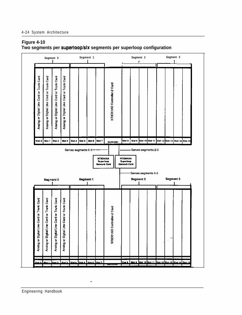
4-24 System Architecture
Figure 4-10Two segments per superloophix segments per superloop configuration
Segment 0 Segment 1 Segment 2 Segment 3
, I‘ ,.I.
Engineering Handbook
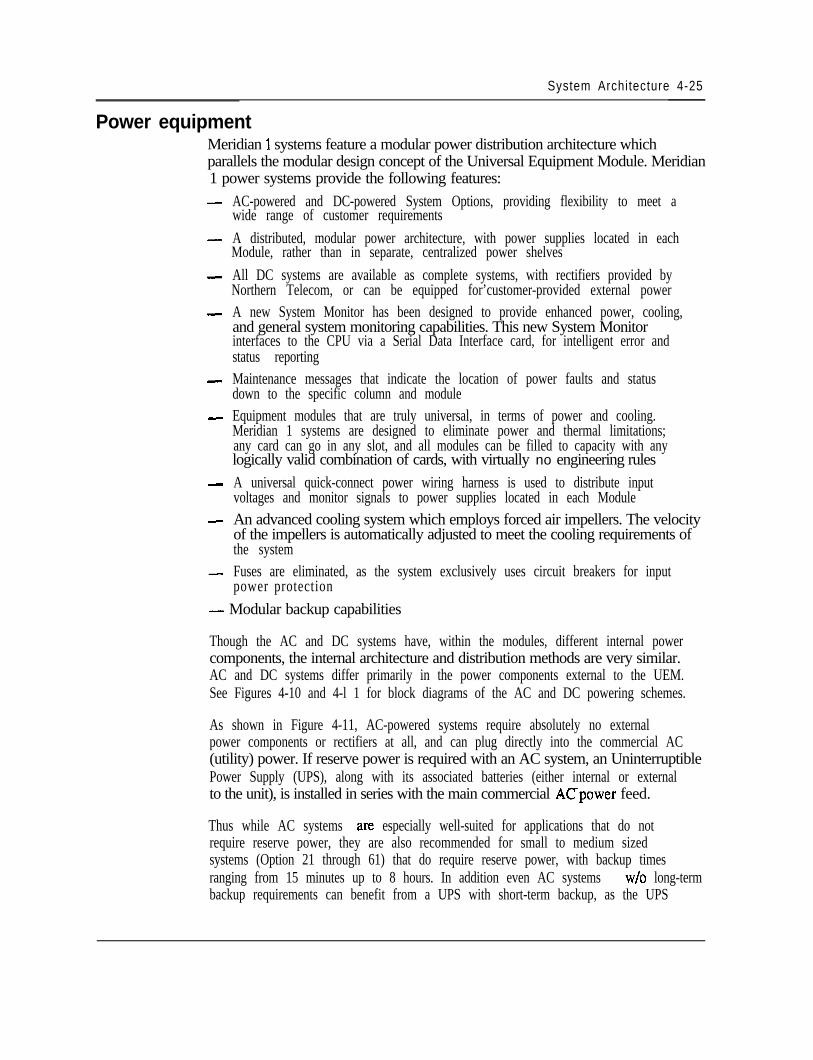
System Architecture 4-25
Power equipmentMeridian 1 systems feature a modular power distribution architecture whichparallels the modular design concept of the Universal Equipment Module. Meridian1 power systems provide the following features:- AC-powered and DC-powered System Options, providing flexibility to meet a
wide range of customer requirements- A distributed, modular power architecture, with power supplies located in each
Module, rather than in separate, centralized power shelves- All DC systems are available as complete systems, with rectifiers provided by
Northern Telecom, or can be equipped for’customer-provided external power- A new System Monitor has been designed to provide enhanced power, cooling,
and general system monitoring capabilities. This new System Monitorinterfaces to the CPU via a Serial Data Interface card, for intelligent error andstatus reporting
- Maintenance messages that indicate the location of power faults and statusdown to the specific column and module
- Equipment modules that are truly universal, in terms of power and cooling.Meridian 1 systems are designed to eliminate power and thermal limitations;any card can go in any slot, and all modules can be filled to capacity with anylogically valid combination of cards, with virtually no engineering rules
- A universal quick-connect power wiring harness is used to distribute inputvoltages and monitor signals to power supplies located in each Module
- An advanced cooling system which employs forced air impellers. The velocityof the impellers is automatically adjusted to meet the cooling requirements ofthe system
- Fuses are eliminated, as the system exclusively uses circuit breakers for inputpower protection
- Modular backup capabilities
Though the AC and DC systems have, within the modules, different internal powercomponents, the internal architecture and distribution methods are very similar.AC and DC systems differ primarily in the power components external to the UEM.See Figures 4-10 and 4-l 1 for block diagrams of the AC and DC powering schemes.
As shown in Figure 4-11, AC-powered systems require absolutely no externalpower components or rectifiers at all, and can plug directly into the commercial AC(utility) power. If reserve power is required with an AC system, an UninterruptiblePower Supply (UPS), along with its associated batteries (either internal or externalto the unit), is installed in series with the main commercial ACpower feed.
Thus while AC systems are especially well-suited for applications that do notrequire reserve power, they are also recommended for small to medium sizedsystems (Option 21 through 61) that do require reserve power, with backup timesranging from 15 minutes up to 8 hours. In addition even AC systems w/o long-termbackup requirements can benefit from a UPS with short-term backup, as the UPS
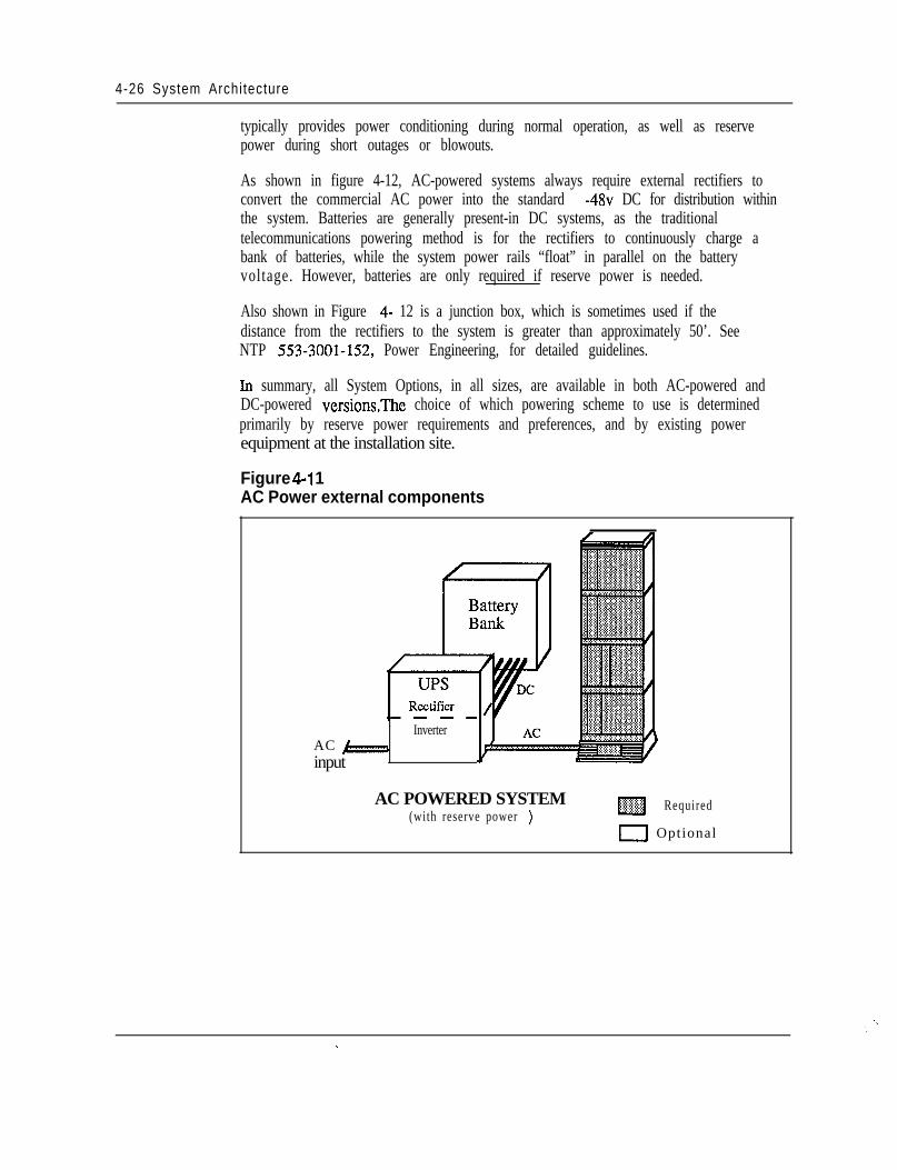
4-26 System Architecture
typically provides power conditioning during normal operation, as well as reservepower during short outages or blowouts.
As shown in figure 4-12, AC-powered systems always require external rectifiers toconvert the commercial AC power into the standard -48~ DC for distribution withinthe system. Batteries are generally present-in DC systems, as the traditionaltelecommunications powering method is for the rectifiers to continuously charge abank of batteries, while the system power rails “float” in parallel on the batteryvoltage. However, batteries are only required if reserve power is needed.
Also shown in Figure 4- 12 is a junction box, which is sometimes used if thedistance from the rectifiers to the system is greater than approximately 50’. SeeNTP 553-3001-152, Power Engineering, for detailed guidelines.
Ln summary, all System Options, in all sizes, are available in both AC-powered andDC-powered versionsThe choice of which powering scheme to use is determinedprimarily by reserve power requirements and preferences, and by existing powerequipment at the installation site.
Figure 4-l 1AC Power external components
InverterAC j---,input
AC POWERED SYSTEM(with reserve power )
m Required
0 Optional
._- ,. .
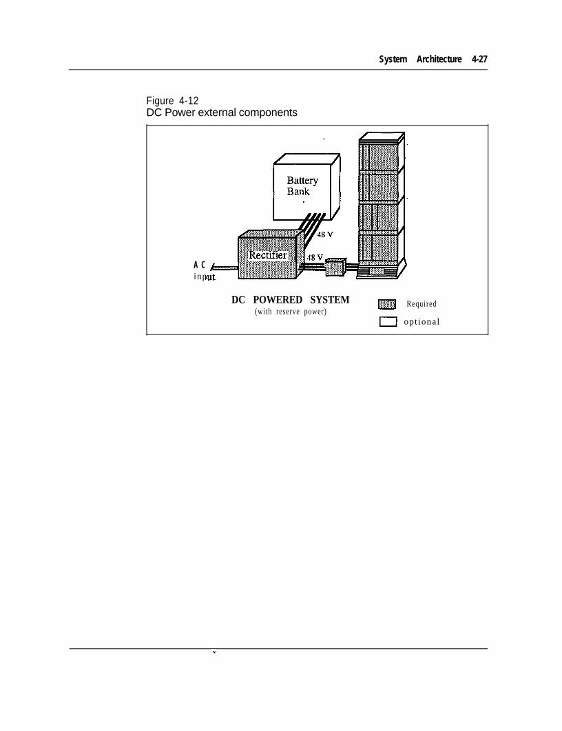
System Architecture 4-27
Figure 4-12DC Power external components
A Cinp
DC POWERED SYSTEM(with reserve power)
m Required
r----J opt ional

Product description 5-l
Chapter 5: Product descriptionContents
IntroductionUniversal Equipment ModulesMeridian 1 System OptionsModule Descriptions
CPU module (NT8D34)CPU/Network module (NT6D39)Network module (NT8D35)Common/Peripheral Equipment module (NT8Dll)Intelligent Peripheral Equipment module (NT8D37)Peripheral Equipment ModuleIntergroup ModuleMeridian Mail Module
Miscellaneous EquipmentCircuit CardsCablingSoftware DescriptionTerminal equipmentPower Equipment
5-l5-35-5
5-145-145-165-185-215-245-265-305 - 3 15-335-385-495-505-535-60
IntroductionThe purpose of this section is to provide a description of the Meridian 1 productline. This information does not replace the Northern Telecom Publications (NTPs).For a list of the available NTPs, please refer to the Master index (553-3001-000).
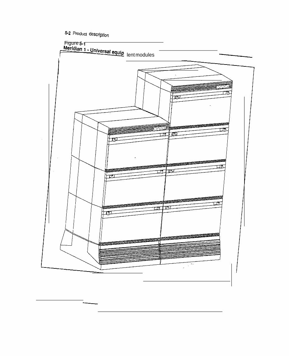
5-2 PrOdUCt CkScription
Figure 5-1I”- -.. .-
lent modules --
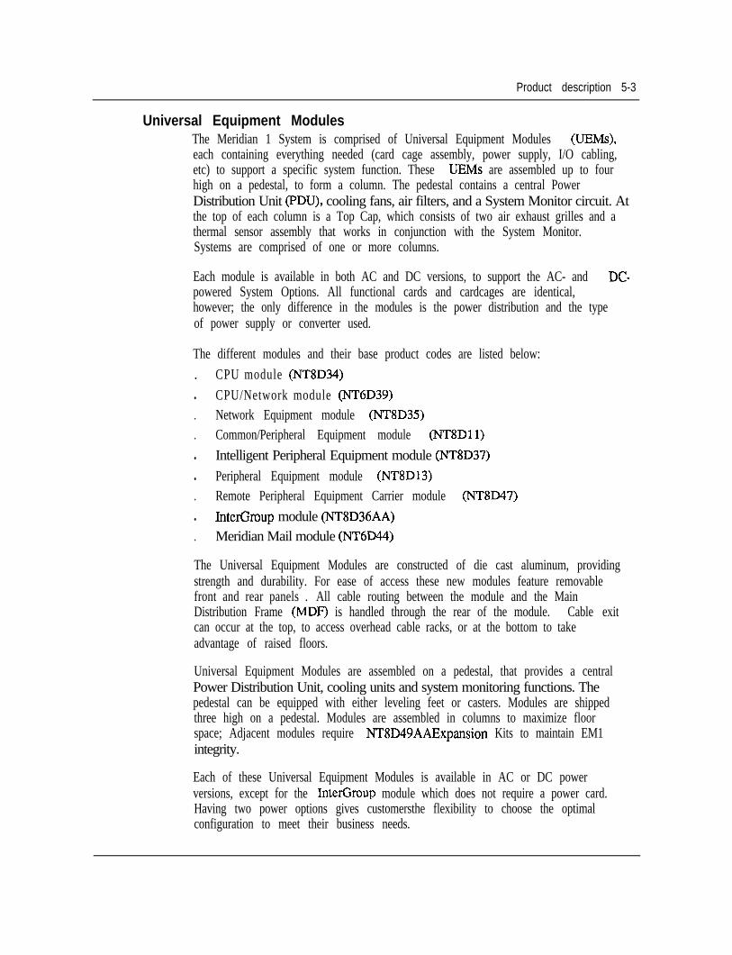
Product description 5-3
Universal Equipment ModulesThe Meridian 1 System is comprised of Universal Equipment Modules (UEMs),each containing everything needed (card cage assembly, power supply, I/O cabling,etc) to support a specific system function. These UEMs are assembled up to fourhigh on a pedestal, to form a column. The pedestal contains a central PowerDistribution Unit (PDU), cooling fans, air filters, and a System Monitor circuit. Atthe top of each column is a Top Cap, which consists of two air exhaust grilles and athermal sensor assembly that works in conjunction with the System Monitor.Systems are comprised of one or more columns.
Each module is available in both AC and DC versions, to support the AC- and DC-powered System Options. All functional cards and cardcages are identical,however; the only difference in the modules is the power distribution and the typeof power supply or converter used.
The different modules and their base product codes are listed below:. CPU module (NT8D34)l CPU/Network module (NT6D39). Network Equipment module (NT8D35). Common/Peripheral Equipment module (NT8Dll)l Intelligent Peripheral Equipment module (NT8D37)l Peripheral Equipment module (NT8Dl3). Remote Peripheral Equipment Carrier module (NT8D47)l InterGroup module (NT8D36AA). Meridian Mail module (NT6D44)
The Universal Equipment Modules are constructed of die cast aluminum, providingstrength and durability. For ease of access these new modules feature removablefront and rear panels . All cable routing between the module and the MainDistribution Frame (MDF) is handled through the rear of the module. Cable exitcan occur at the top, to access overhead cable racks, or at the bottom to takeadvantage of raised floors.
Universal Equipment Modules are assembled on a pedestal, that provides a centralPower Distribution Unit, cooling units and system monitoring functions. Thepedestal can be equipped with either leveling feet or casters. Modules are shippedthree high on a pedestal. Modules are assembled in columns to maximize floorspace; Adjacent modules require NT8D49AAExpansion Kits to maintain EM1integrity.
Each of these Universal Equipment Modules is available in AC or DC powerversions, except for the InterGroup module which does not require a power card.Having two power options gives customersthe flexibility to choose the optimalconfiguration to meet their business needs.
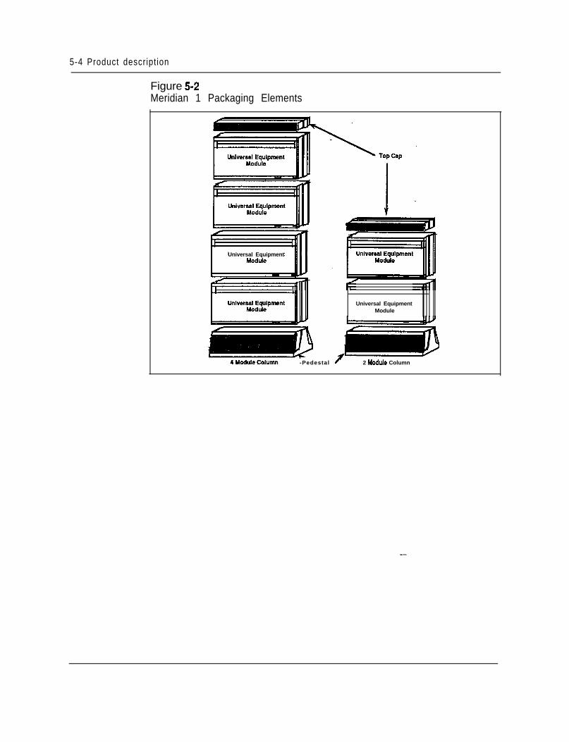
5-4 Product descript ion
Figure 5-2Meridian 1 Packaging Elements
Universal Equipment
-Pedestal f 2 Module Column
Universal EquipmentModule
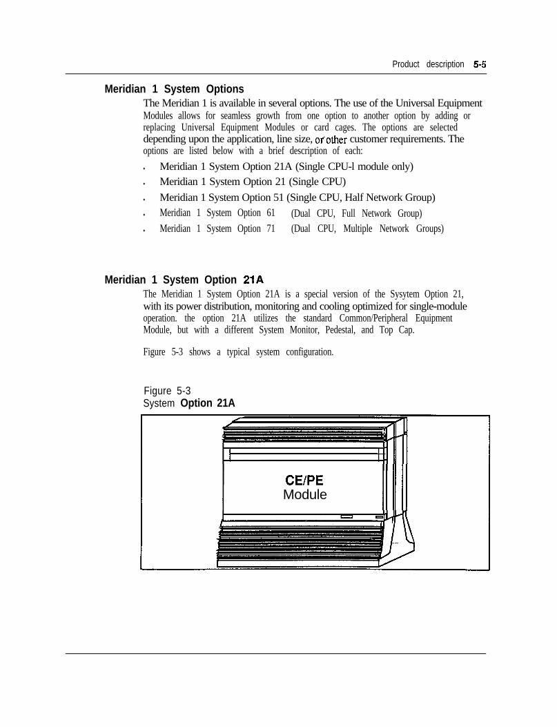
Product description 5-5
Meridian 1 System OptionsThe Meridian 1 is available in several options. The use of the Universal EquipmentModules allows for seamless growth from one option to another option by adding orreplacing Universal Equipment Modules or card cages. The options are selecteddepending upon the application, line size, orother customer requirements. Theoptions are listed below with a brief description of each:l Meridian 1 System Option 21A (Single CPU-l module only)l Meridian 1 System Option 21 (Single CPU)l Meridian 1 System Option 51 (Single CPU, Half Network Group)l Meridian 1 System Option 61 (Dual CPU, Full Network Group)l Meridian 1 System Option 71 (Dual CPU, Multiple Network Groups)
Meridian 1 System Option 21AThe Meridian 1 System Option 21A is a special version of the Sysytem Option 21,with its power distribution, monitoring and cooling optimized for single-moduleoperation. the option 21A utilizes the standard Common/Peripheral EquipmentModule, but with a different System Monitor, Pedestal, and Top Cap.
Figure 5-3 shows a typical system configuration.
Figure 5-3System Option 21A
CEIPEModule
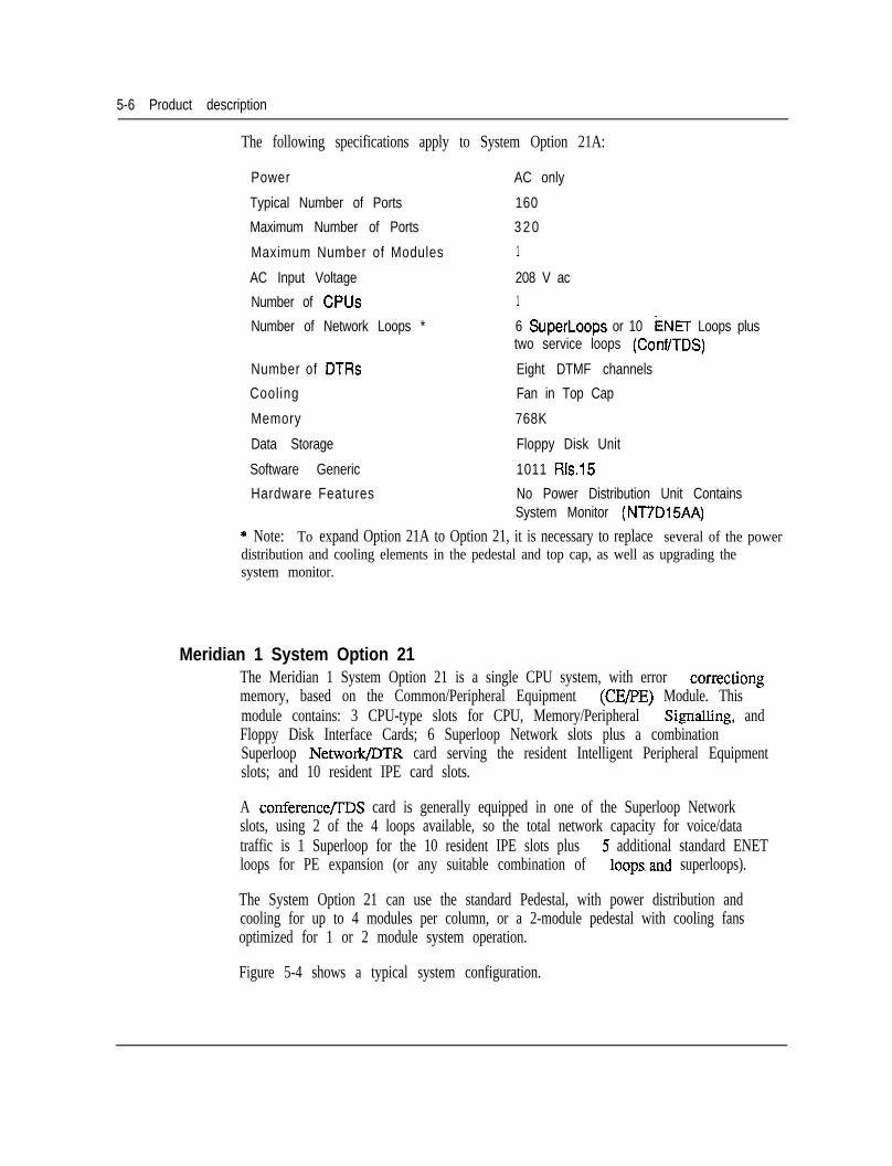
5-6 Product description
The following specifications apply to System Option 21A:
Power AC only
Typical Number of Ports 160
Maximum Number of Ports 3 2 0
Maximum Number of Modules 1
AC Input Voltage 208 V ac
Number of CPUs 1
Number of Network Loops * 6 SuperLoops or 10 ENET Loops plustwo service loops (ConWTDS)
Number of DTRs Eight DTMF channels
Cooling Fan in Top Cap
Memory 768K
Data Storage Floppy Disk Unit
Software Generic 1011 RIs.15
Hardware Features No Power Distribution Unit ContainsSystem Monitor (NT7D15AA)
* Note: To expand Option 21A to Option 21, it is necessary to replace several of the powerdistribution and cooling elements in the pedestal and top cap, as well as upgrading thesystem monitor.
Meridian 1 System Option 21The Meridian 1 System Option 21 is a single CPU system, with error correctiongmemory, based on the Common/Peripheral Equipment (CELPE) Module. Thismodule contains: 3 CPU-type slots for CPU, Memory/Peripheral SignaIling, andFloppy Disk Interface Cards; 6 Superloop Network slots plus a combinationSuperloop Network/DTR card serving the resident Intelligent Peripheral Equipmentslots; and 10 resident IPE card slots.
A conference/rDS card is generally equipped in one of the Superloop Networkslots, using 2 of the 4 loops available, so the total network capacity for voice/datatraffic is 1 Superloop for the 10 resident IPE slots plus 5 additional standard ENETloops for PE expansion (or any suitable combination of loopsand superloops).
The System Option 21 can use the standard Pedestal, with power distribution andcooling for up to 4 modules per column, or a 2-module pedestal with cooling fansoptimized for 1 or 2 module system operation.
Figure 5-4 shows a typical system configuration.
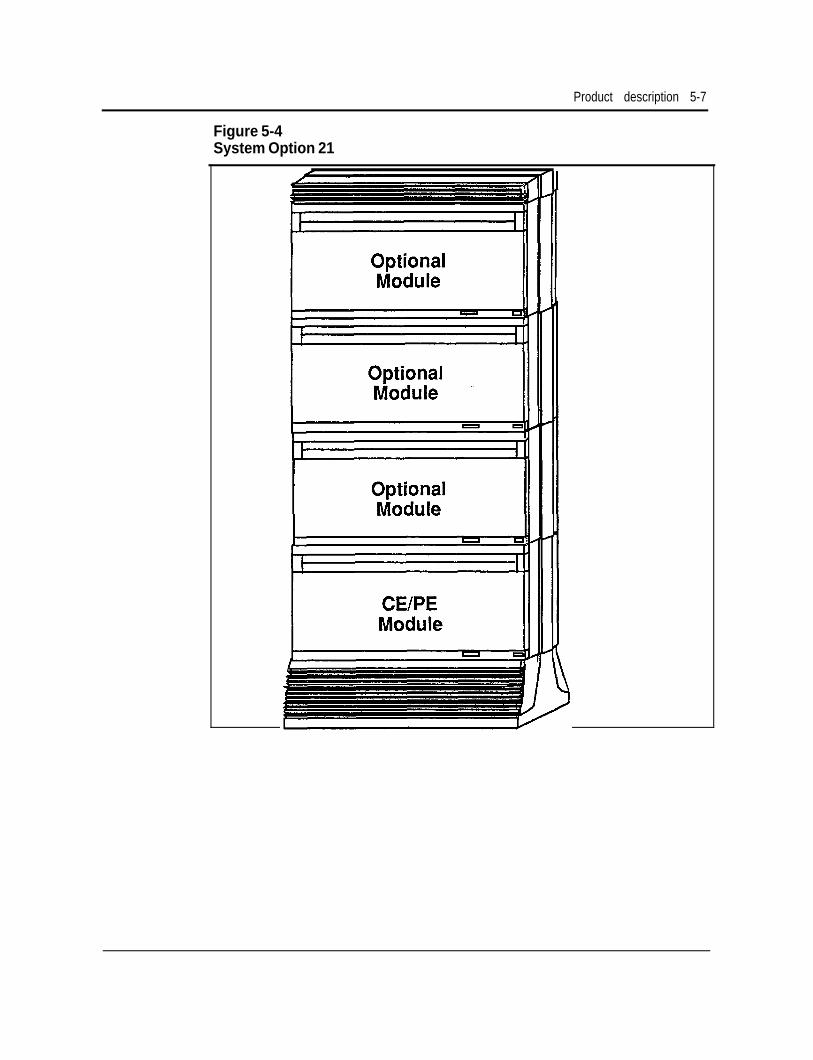
Product description 5-7
Figure 5-4System Option 21
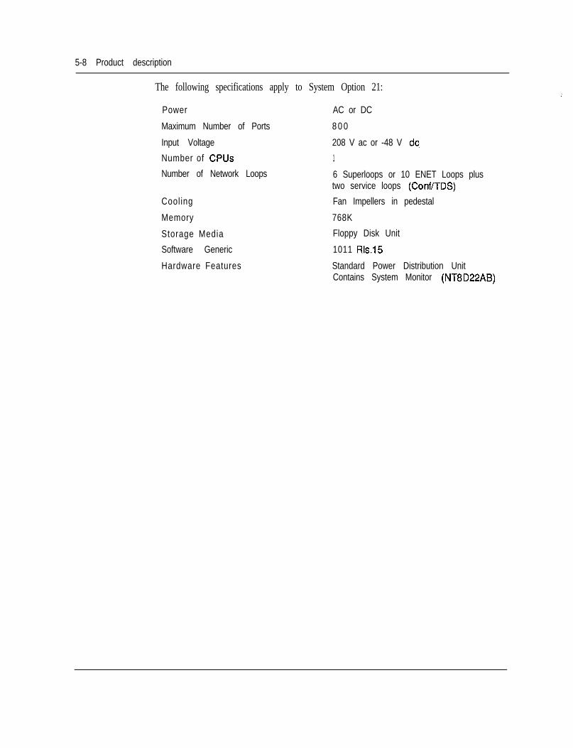
5-8 Product description
The following specifications apply to System Option 21:
Power
Maximum Number of Ports
Input Voltage
Number of CPUs
Number of Network Loops
Cooling
Memory
Storage Media
Software Generic
Hardware Features
AC or DC
8 0 0
208 V ac or -48 V dc
1
6 Superloops or 10 ENET Loops plustwo service loops (Conf/TDS)
Fan Impellers in pedestal
768K
Floppy Disk Unit
1011 Rls.15
Standard Power Distribution UnitContains System Monitor (NT8D22AB)
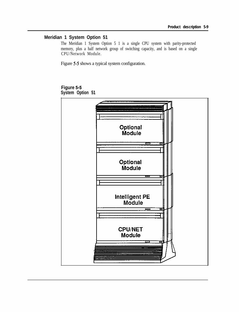
Product description 5-9
Meridian 1 System Option 51The Meridian 1 System Option 5 1 is a single CPU system with parity-protectedmemory, plus a half network group of switching capacity, and is based on a singleCPU/Network Module.
Figure 5-5 shows a typical system configuration.
Figure 5-5System Option 51
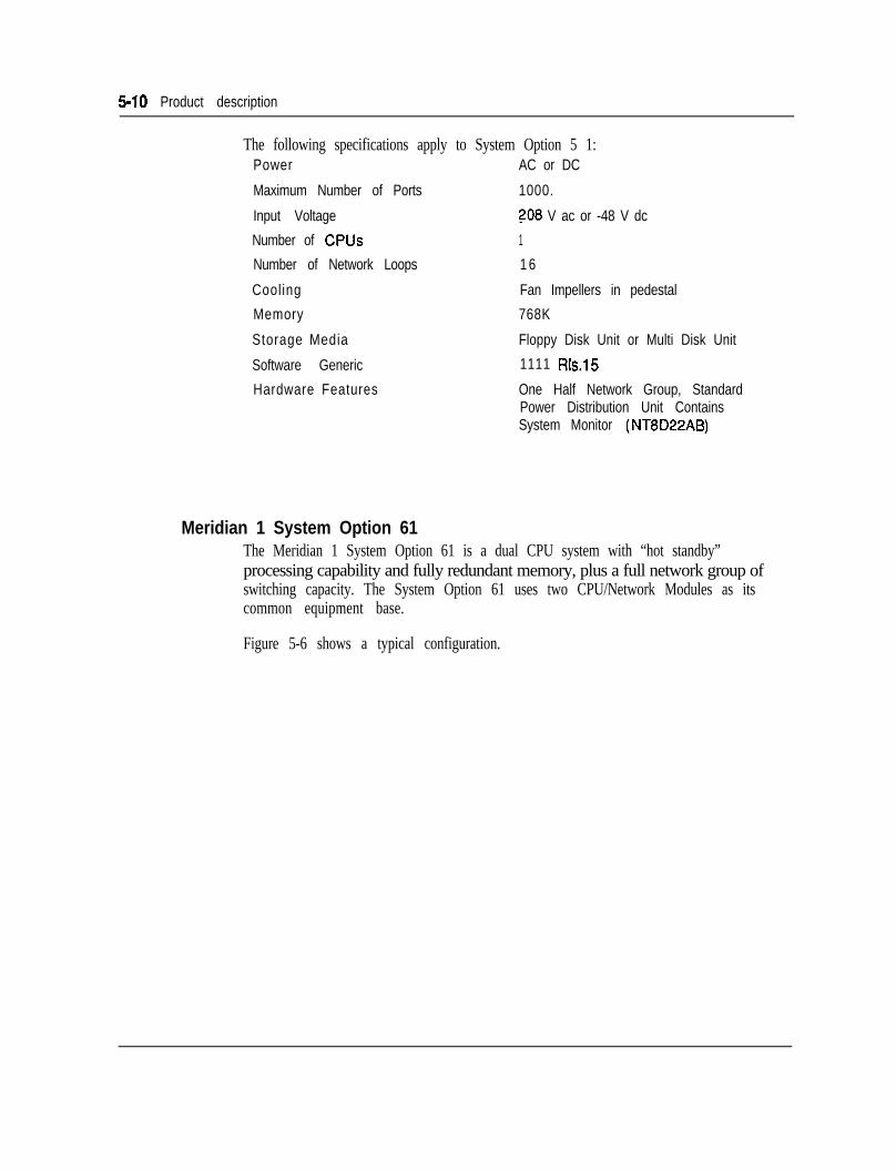
5-10 Product description
The following specifications apply to System Option 5 1:Power AC or DC
Maximum Number of Ports 1000.
Input Voltage ?08 V ac or -48 V dc
Number of CPUs 1
Number of Network Loops 1 6
Cooling Fan Impellers in pedestal
Memory 768K
Storage Media Floppy Disk Unit or Multi Disk Unit
Software Generic 1111 Rls.15
Hardware Features One Half Network Group, StandardPower Distribution Unit ContainsSystem Monitor (NT8D22AB)
Meridian 1 System Option 61The Meridian 1 System Option 61 is a dual CPU system with “hot standby”processing capability and fully redundant memory, plus a full network group ofswitching capacity. The System Option 61 uses two CPU/Network Modules as itscommon equipment base.
Figure 5-6 shows a typical configuration.
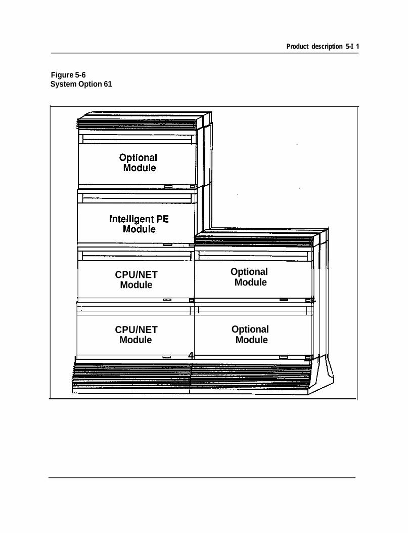
Product description 5-I 1
Figure 5-6System Option 61
CPU/NETModule
OptionalModule
J - 4 -I I 1 I .
CPU/NET OptionalModule Module
I - 4 u
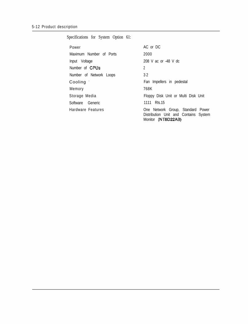
5-12 Product description
Specifications for System Option 61:
Power
Maximum Number of Ports
Input Voltage
Number of CPUs
Number of Network Loops
Cooling ’
Memory
Storage Media
Software Generic
Hardware Features
AC or DC
2000
208 V ac or -48 V dc
2
3 2
Fan Impellers in pedestal
768K
Floppy Disk Unit or Multi Disk Unit
1111 RIs.15
One Network Group, Standard PowerDistribution Unit and Contains SystemMonitor (NT8D22AB)
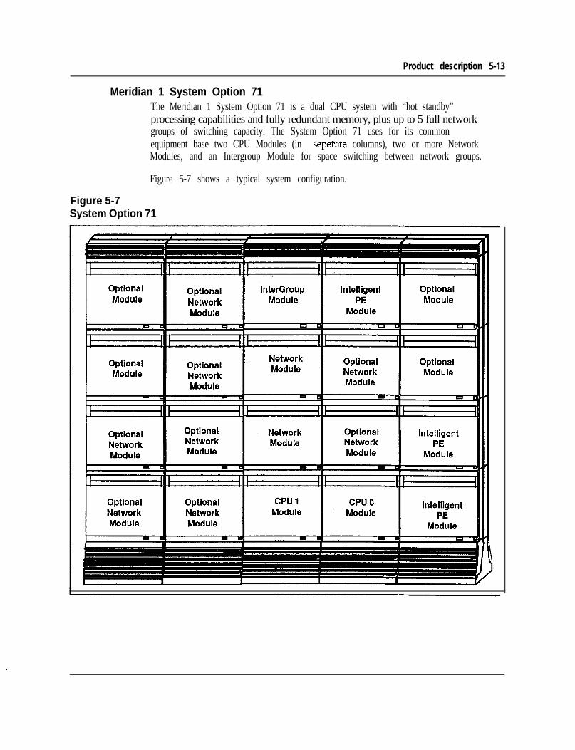
Product description 5-13
Meridian 1 System Option 71The Meridian 1 System Option 71 is a dual CPU system with “hot standby”processing capabilities and fully redundant memory, plus up to 5 full networkgroups of switching capacity. The System Option 71 uses for its commonequipment base two CPU Modules (in seperate columns), two or more NetworkModules, and an Intergroup Module for space switching between network groups.
Figure 5-7 shows a typical system configuration.
Figure 5-7System Option 71
5-14 Product description
Specifications for System Option 71:
Power
Maximum Number of Ports
Input Voltage
Number of CPUs
Number of Network Loops
Cooling
Memory
Storage Media
Software Generic
Hardware Features
AC or DC
10,000
208 V ac or -48 V dc
2
160
Fan Impellers in pedestal
1.5 Mbyte
Floppy Disk Unit or Multi Disk Unit
1211 Rls.15
Up to five Network Groups, StandardPower Distribution Unit and ContainsSystem Monitor (NT8D22AB)
Module descriptionsCPU module (NT8D34)The NT8D34 CPU module uses the CPU and Memory cards currently housed in theMeridian SL-1 XT CPU/MEM shelf to provide system control and storage of dataand programs for the Meridian 1 System Option 71. Each NT8D34 CPU modulehouses one CPU; two are required for the Meridian 1 System Option 71.
For configuration flexibility the NT8D34 CPU module is available with an ACpower supply option or a DC power supply option. These power supplies providethe voltages to operate the circuit cards located in the Modules.
The NT8D34AA module is designed to accommodate AC power supplies. OneCommon Equipment Power Supply AC (NT8D29AB) is required for theNT8D34AA module.
The NT8D34DC module is designed to accommodate DC power supplies. OneCommon Equipment Power Supply DC (NT6D4 1AB) is required for theNT8D34DC module.
Configuration guidelines: -l NT8D34 CPU Modules are located side by side on the first level of adjacent
columns.
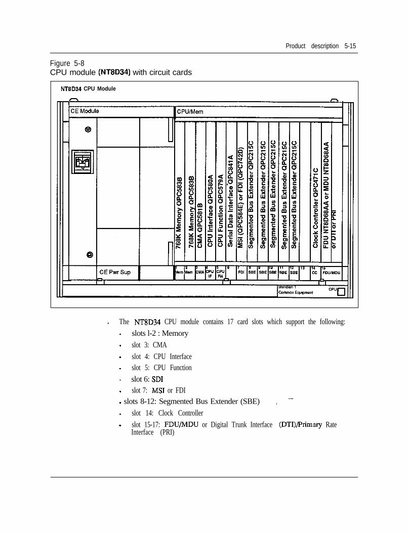
Product description 5-15
Figure 5-8CPU module (NT8D34) with circuit cards
NT8D34 CPU Module
l The NT8D34 CPU module contains 17 card slots which support the following:- slots l-2 : Memory- slot 3: CMA- slot 4: CPU Interface- slot 5: CPU Function- slot 6: SD1- slot 7: MS1 or FDI- slots 8-12: Segmented Bus Extender (SBE) ,- slot 14: Clock Controller- slot 15-17: FDU/MDU or Digital Trunk Interface (DTI)/Primary Rate
Interface (PRI)
5-16 Product description
CPU/Network module (NT6D39)The NT6D39 CPU/Network module uses the CPU and Memory circuit cardshoused in the Meridian SL-1 NT and RT CPU/MEM shelves to provide systemcontrol and storage of data and programs for Meridian 1 System Option 5 1 and 61.Each NT6D39 module houses one CPU and up to 16 network loops, with oneNT6D39 CPU/Net module used in System Options 51 and two used in SystemOption 6 1.
For configuration flexibility the NT6D39 CPU/Network module is available with anAC power supply option or a DC power supply option. These-power suppliesprovide the voltages to operate the circuit cards located in the Modules.
The NT6D39AA module is designed to accommodate one Common EquipmentPower Supply AC (NT8D29AB).
The NT6D39DC module is designed to accommodate one Common EquipmentPower Supply DC (NT6D4 1 AB).
Contiguration guidelines:l For a half group, single CPU system, one NT6D39 module is required
(Meridian 1 System Option 51).. For a full group, dual CPU system, two NT6D39 Modules are required
(Meridian 1 System Option 61).l These NT8D39 Modules must be located on top of each other in the same
column.
--
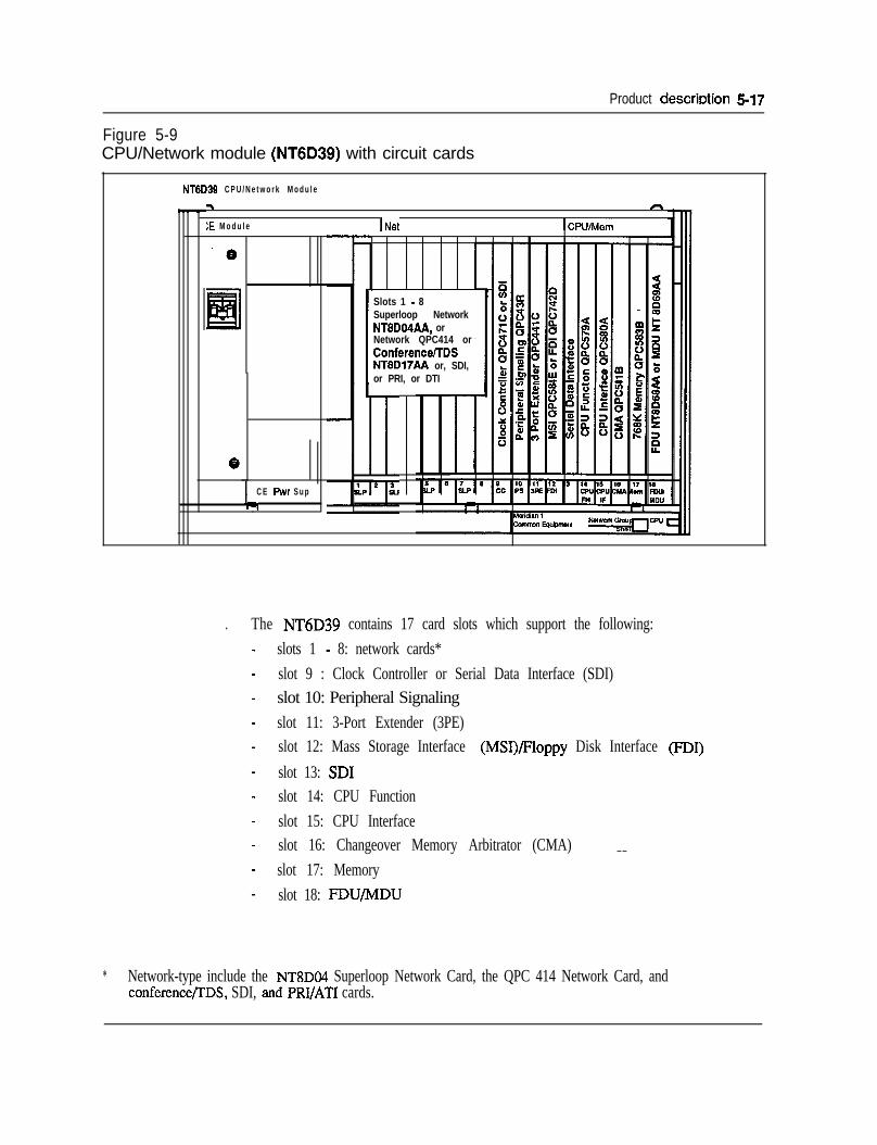
Product descrbtion 5-17
Figure 5-9CPU/Network module (NT6D39) with circuit cards
NT6D39 C P U / N e t w o r k M o d u l e
:E M o d u l e INfd
CI
ICPlJ/Mem
C E Pwr S u p
%
Slots 1 - 8Superloop NetworkNT8D04AA, orNetwork QPC414 orConferencelTDSNT8D17AA or, SDI,or PRI, or DTI
. The NT6D39 contains 17 card slots which support the following:slots 1 - 8: network cards*slot 9 : Clock Controller or Serial Data Interface (SDI)slot 10: Peripheral Signalingslot 11: 3-Port Extender (3PE)slot 12: Mass Storage Interface (MSI)/Floppy Disk Interface @I)slot 13: SD1slot 14: CPU Functionslot 15: CPU Interfaceslot 16: Changeover Memory Arbitrator (CMA)slot 17: Memoryslot 18: FDWMDU
_ _
* Network-type include the NT8DO4 Superloop Network Card, the QPC 414 Network Card, andconference/rDS, SDI, and PRI/ATI cards.
5-18 Product description
Network module (NT8D35) i. ;The NT8D35 Network module contains the network shelf backplane from theMeridian SL-1 Network Enhanced systems but is housed in a module configuration.This module will support the current Meridian SL- 1 network circuit cards alongwith two new network circuit cards: -l SuperLoop Network card (NT8DO4)l Conference/Tone and Digit Switch card (NT8D17)
The new SuperLoop Network card (NT8DO4) will interface to four network loops(120 time slots) and may also be used in the existing Meridian SL-1 EnhancedNetwork shelves.
The Conference (QPC444) and the Tone and Digit Switch (QPC609) circuit cardsmay be replaced by the Conference/I’DS card (NT8D17)) which will require twoloops (one card slot), instead of the four loops (two card slots) currently requiredwith the Meridian SL- 1 systems.
For configuration flexibility the NT8D35 Network module is available with an ACpower option or a DC power option. These power supplies provide the voltages tooperate the circuit cards located in the modules.
The NT8D35AA Network module is designed to accommodate the one CommonEquipment Power Supply AC (NT8D29AA).
The NT8D35DC module is designed to accommodate one Common EquipmentPower Supply DC (NT6D41AB).
The NT8D35 Network module will permit eight QPC414 (ENET) cards or fourNT8DO4AA SuperLoop Network cards, or any combination for a total of 16network loops per NT8D35 module. Usually 14 voice/data loops are availablewhen one Conference/Tone and Digit Switch card is configured in the NT8D35module.
Card slots 5 - 12 are used for the network cards. The SuperLoop Network card willalways use four loops (120 time slots) and will always begin with an even numberedloop that is a multiple of four (Example - 4,8, 12, 16,20,24,28 etc...). Seeconfiguration guidelines for SuperLoop Network and ENET card placement rules.
-
Product description 5-19
Each NT8D35 module will provide 16 ENET loops or four Superloops, one half anetwork group. Two NT8D35 modules are required for a complete network groupof 32 loops.
The NT8D35 Network modules are designated as:*Group 0 module 0 , Group 0 module 1*Group 1 module 0 , Group 1 module 1(continued)*Group 2 module 0 , Group 2 module 1*Group 3 module 0 , Group 3 module 1*Group 4 module 0 , Group 4 module 1
The Group and module numbers are determined by the switch settings on the ThreePort Extender (3PE) card.
The NT8D35 module may be utilized to support Digital Trunk Interface (DTI)and/or a Primary Rate Interface (PRI) card. In this configuration one commonequipment power supply is required to power up to six DTI/PRI cards.Configuration guidelines:
The NT8D35 Modules do not have a left and right hand version as with theMeridian SL-1 network shelves. In a full network group configuration, theModules must always be one on top of the other.The terminal number O-O-O-O is software reserved and may not be used for anyPE terminal numbers. To avoid using this TN it is recommended you assignloop 0 as a Conference loop and loop 1 for a TDS loop (card slot 5).A maximum of 10 NT8D35 Modules (5 network groups) (System Option 71only).A maximum of 6 DTI/PRI cards per NT8D35.When the Superloop Network card is used, the card slot to the left or right maynot be used for other network cards (ENET or Superloop Network). The emptycard slots may house DTI/PRI cards, if two card slots are adjacent to each other,or other type cards that do not require network addressing (SD1 etc...).All cabling will exit the module from the rear, via I/O panels.All faceplate cables must go to the &&of every module and terminate on I/Opanels, when exiting module.The NT8D35 contains 15 card slots which support the following:- slots 1: 3PE- slots 2-3: InterGroup Switch (IGS) 1, DTI/PRI, or SD1- slot 4: Peripheral Signaling- slots 5-12: Network Cards- slot 13: DTI/PRI or SDI/QSDI/ESDI/DCHI
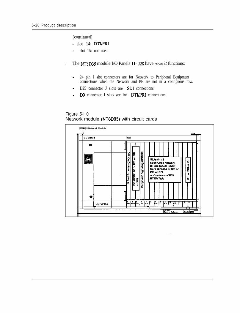
5-20 Product description
(continued)- slot 14: DTI/PRI- slot 15: not used
l The NT8D35 module I/O Panels Jl - 528 have sever&l functions:
- 24 pin J slot connectors are for Network to Peripheral Equipmentconnections when the Network and PE are not in a contiguous row.
- D25 connector J slots are SD1 connections.- D9 connector J slots are for DTI/PRI connections.
Figure 5-l 0Network module (NT8D35) with circuit cards
NT3D3L Network Module
3E Module 1 Net
Product description 5-21
Common/Peripheral Equipment module (NT8Dll)The NT8Dll module is utilized to house common, network and peripheralequipment circuit cards for the Meridian 1 System Options 21A and 21.
The NT8Dll CE/PE module is available in-two versions, AC or DC power. Thesepower supplies provide the voltages to operate the circuit cards located in themodules.l The N8DllAA CE/PE module requires one
Common Equipment Power Supply AC (NT7D14AA).. The N8DllDC CE/PE module requires one
Common Equipment Power Supply DC (NT7DO4AA).
This module is divided into two sections:9 Common Equipment (CE)l Peripheral Equipment (PE)
There are 10 Common Equipment (CE) and 10 Peripheral Equipment (PE) cardslots. The CPU functions are provided by card slots l-3. The Network Equipmentfunctions are provided by card slots 3-10.
The CPU circuit card (QPC687), used in the Meridian SL-1ST system, is installedin CE card slot 2.
The NT8Dll module uses two specially designed circuit cards for Meridian 1System Options 21A and 2 1 only.l Memory/Signaling card (NT8D19AA)l Network/DTR card (NT8D18AA)
The Memory/Signalling circuit card installed in CE card slot 3 provides theperipheral signaling functions in addition to providing the memory andmiscellaneous CPU equipment functions.
The Network/DTR circuit card will provide the Controller card (NT8DOl) functionsfor the Intelligent PE cards installed in the NT.8Dll module, along with a SuperloopNetwork and Digitone Receiver functions, for Meridian 1 System Options 21,21A.The Network/DTR card is installed in CE card slot 10. This card also provides aSuperloop for all ten Intelligent PE cards, and eight DTR circuits. Superloopnetworks (NT8DO4) and/or ENETs (QPC414) are used whenexpansion is requiredby adding more PE Modules.
For uniformity, it is recommended that theFloppy Disk Interface circuit card beinstalled in CE card slot 1. This card provides the CPU interface to the MassStorage Device. A Floppy Disk Unit may replace the MS1 and Mass storage devicein some systems. This FDU may be installed in CE card slots 7-9 or in PE cardslots 7- 10.
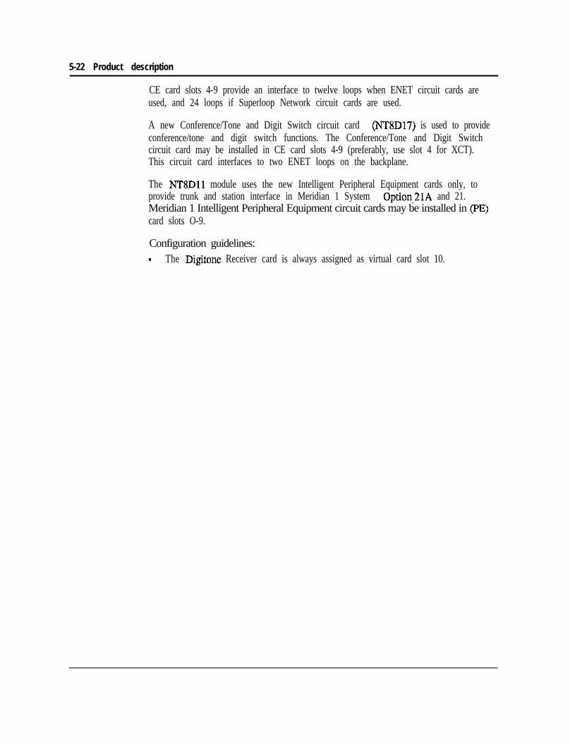
5-22 Product description
CE card slots 4-9 provide an interface to twelve loops when ENET circuit cards areused, and 24 loops if Superloop Network circuit cards are used.
A new Conference/Tone and Digit Switch circuit card (NT8D17) is used to provideconference/tone and digit switch functions. The Conference/Tone and Digit Switchcircuit card may be installed in CE card slots 4-9 (preferably, use slot 4 for XCT).This circuit card interfaces to two ENET loops on the backplane.
The NT8Dll module uses the new Intelligent Peripheral Equipment cards only, toprovide trunk and station interface in Meridian 1 System Option_:!lA and 21.Meridian 1 Intelligent Peripheral Equipment circuit cards may be installed in pE)card slots O-9.
Configuration guidelines:9 The Digitone Receiver card is always assigned as virtual card slot 10.
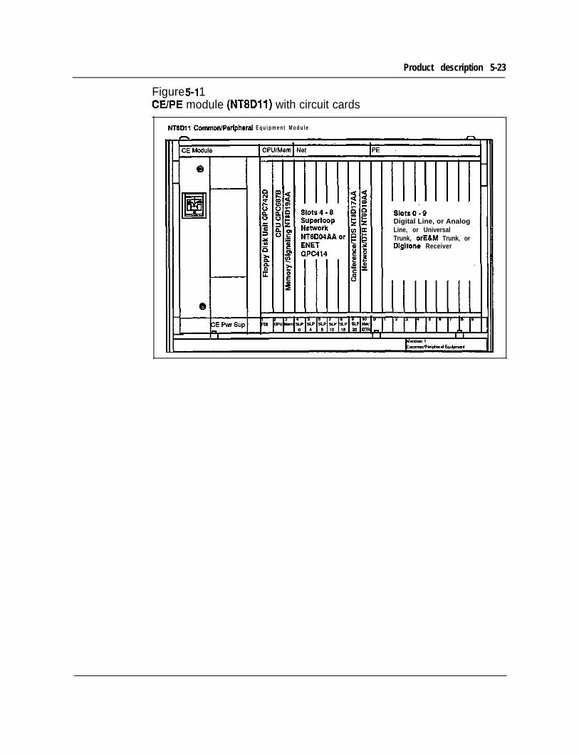
Product description 5-23
Figure 5-l 1CElPE module (NT8Dll) with circuit cards
NTBDll Common/Peripheral E q u i p m e n t M o d u l e
Digital Line, or AnalogLine, or UniversalTrunk, orE&M Trunk, orDigitone Receiver
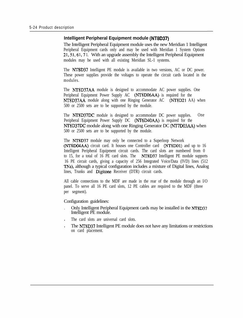
5-24 Product description
Intelligent Peripheral Equipment module (NT8D37)The Intelligent Peripheral Equipment module uses the new Meridian 1 IntelligentPeripheral Equipment cards only and may be used with Meridian 1 System Options21,s 1,61,7 1. With an upgrade assembly the Intelligent Peripheral Equipmentmodules may be used with all existing Meridian SL-1 systems.
The NT8D37 Intelligent PE module is available in two versions, AC or DC power.These power supplies provide the voltages to operate the circuit cards located in themodules.
The NT8D37AA module is designed to accommodate AC power supplies. OnePeripheral Equipment Power Supply AC (NT8D06AA) is required for theNT8D37AA module along with one Ringing Generator AC (NT8D21 AA) when500 or 2500 sets are to be supported by the module.
The NT8D37DC module is designed to accommodate DC power supplies. OnePeripheral Equipment Power Supply DC (NT6D40AA) is required for theNT8D37DC module along with one Ringing Generator DC (NT7D03AA) when500 or 2500 sets are to be supported by the module.
The NT8D37 module may only be connected to a Superloop Network(NT8DO4AA) circuit card. It houses one Controller card (NT8DOl) and up to 16Intelligent Peripheral Equipment circuit cards. The card slots are numbered from 0to 15, for a total of 16 PE card slots. The NT8D37 Intelligent PE module supports16 PE circuit cards, giving a capacity of 256 Integrated Voice/Data (IVD) lines (512TNs), although a typical configuration includes a mixture of Digital lines, Analoglines, Trunks and Digitone Receiver (DTR) circuit cards.
All cable connections to the MDF are made in the rear of the module through an I/Opanel. To serve all 16 PE card slots, 12 PE cables are required to the MDF (threeper segment).
Configuration guidelines:. Only Intelligent Peripheral Equipment cards may be installed in the NT8D37
Intelligent PE module.l The card slots are universal card slots.l The NT8D37 Intelligent PE module does not have any limitations or restrictions
on card placement.
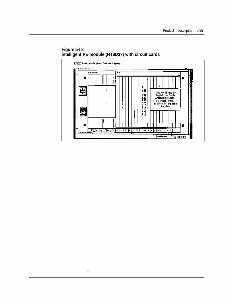
Product description 5-25
Figure 5-l 2Intelligent PE module (NT8D37) with circuit cards
NT8W7 M~illgmt Pwlphw,, Equipmmt Modul.
PEPrnSup ~Rnge.9
mSlots 0 - 15 may beDigital Line Cards
Analoa Line Cards.~.Uni&al Trunks,
E&M Trunks, DigitoneReceiver
0
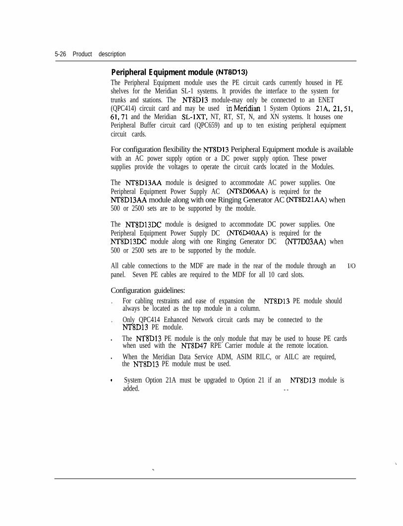
5-26 Product description
Peripheral Equipment module (NT8D13)The Peripheral Equipment module uses the PE circuit cards currently housed in PEshelves for the Meridian SL-1 systems. It provides the interface to the system fortrunks and stations. The NT8D13 module-may only be connected to an ENET(QPC414) circuit card and may be used inMeridian 1 System Options 21A, 21,51,61,71 and the Meridian SL-lXT, NT, RT, ST, N, and XN systems. It houses onePeripheral Buffer circuit card (QPC659) and up to ten existing peripheral equipmentcircuit cards.
For configuration flexibility the NT8D13 Peripheral Equipment module is availablewith an AC power supply option or a DC power supply option. These powersupplies provide the voltages to operate the circuit cards located in the Modules.
The NT8Dl3AA module is designed to accommodate AC power supplies. OnePeripheral Equipment Power Supply AC (lNT8D06AA) is required for theNT8D13AA module along with one Ringing Generator AC (NT8D21AA) when500 or 2500 sets are to be supported by the module.
The NT8D13DC module is designed to accommodate DC power supplies. OnePeripheral Equipment Power Supply DC (NT6D40AA) is required for theNT8D13DC module along with one Ringing Generator DC (NT7D03AA) when500 or 2500 sets are to be supported by the module.
All cable connections to the MDF are made in the rear of the module through an I/Opanel. Seven PE cables are required to the MDF for all 10 card slots.
Configuration guidelines:. For cabling restraints and ease of expansion the NT8D13 PE module should
always be located as the top module in a column.. Only QPC414 Enhanced Network circuit cards may be connected to the
NT8D13 PE module.l The NT8D13 PE module is the only module that may be used to house PE cards
when used with the NT8D47 RPE Carrier module at the remote location.l When the Meridian Data Service ADM, ASIM RILC, or AILC are required,
the NT8D13 PE module must be used.
. System Option 21A must be upgraded to Option 21 if an NT8D13 module isadded. - -
‘.
U . .
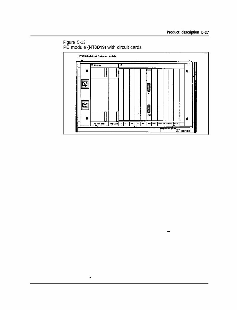
Product description 5-27
Figure 5-13PE module (NT8D13) with circuit cards
5-28 Product description
Remote Peripheral Equipment Carrier module (NT8D47)The NT8D47AA/DC RPE Carrier module is used to extend the Network to PEinterconnection distance between local and remote sites. It accommodates twonetwork loops.
For configuration flexibility the Remote Peripheral Equipment Carrier module isavailable with an AC power option or a DC power option. These power suppliesprovide the voltages to operate the circuit cards located in the modules
The NT8D47AA RPE Carrier module is designed to accommodate AC powersupplies. One Common Equipment Power Supply AC (NT8D29AA) is required forthe N8D47AA module.
The NT8D47DC RPE Carrier module is designed to accommodate DC powersupplies. One Common Equipment PowerSupply DC (NT6D41AB) is required forthe NT8D47DC module.
Configuration guidelines:l Since each RPE Carrier module serves two network loops, the number of
modules required per system depends on the number of peripheral devices andtraffic requirements at the remote site.
l The RPE backplane contains 12 card slots which support the following:- slot 1: DTI- slot 2: 1.5 Mb Converter- slot 3: 2 Mb Converter- slot 4: Carrier Interface- slot 5: Remote Peripheral- slot 6: Local Carrier Buffer- slot 7: Carrier Interface- slot 8: 2 Mb Converter- slot 9: 1.5 Mb Converter- slot 10: Carrier Maintenance- slots 11-12: DTI
_-
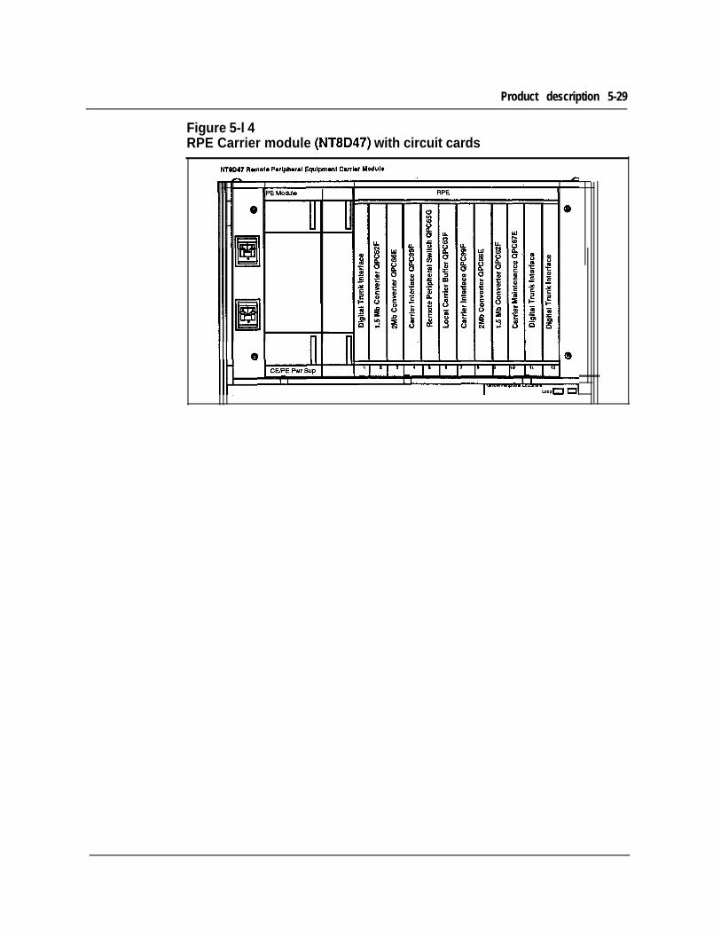
Product description 5-29
Figure 5-l 4RPE Carrier module (NT8D47) with circuit cards
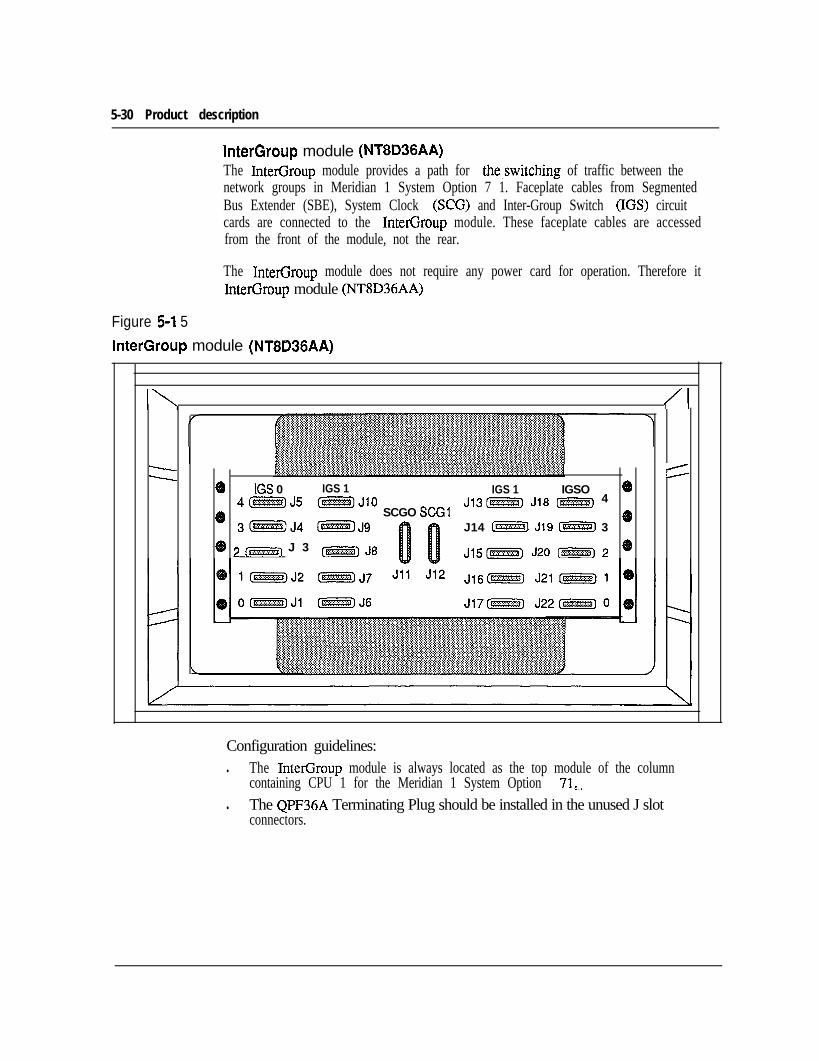
5-30 Product description
InterGroup module (NT8D36AA)The InterGroup module provides a path for the,switching of traffic between thenetwork groups in Meridian 1 System Option 7 1. Faceplate cables from SegmentedBus Extender (SBE), System Clock (SCG) and Inter-Group Switch (IGS) circuitcards are connected to the InterGroup module. These faceplate cables are accessedfrom the front of the module, not the rear.
The InterGroup module does not require any power card for operation. Therefore itInterGroup module (NT8D36AA)
Figure 5-l 5InterGroup module (NT8D36AA)
I\ /I
- 4- /
a IGS 0 IGS 1 IGS 1 IGSO @4mJ5 -JjO J13[-j J18 m 4
e SCGO SCGI3@i!i@@J4 -J9 J14 @%%%I J19 @@ii% 3
e
0 3 (m, J 3 c-1 J8 J15[-] J20 (m-j 2 49
Configuration guidelines:l The InterGroup module is always located as the top module of the column
containing CPU 1 for the Meridian 1 System Option 71,-l The QPF36A Terminating Plug should be installed in the unused J slot
connectors.
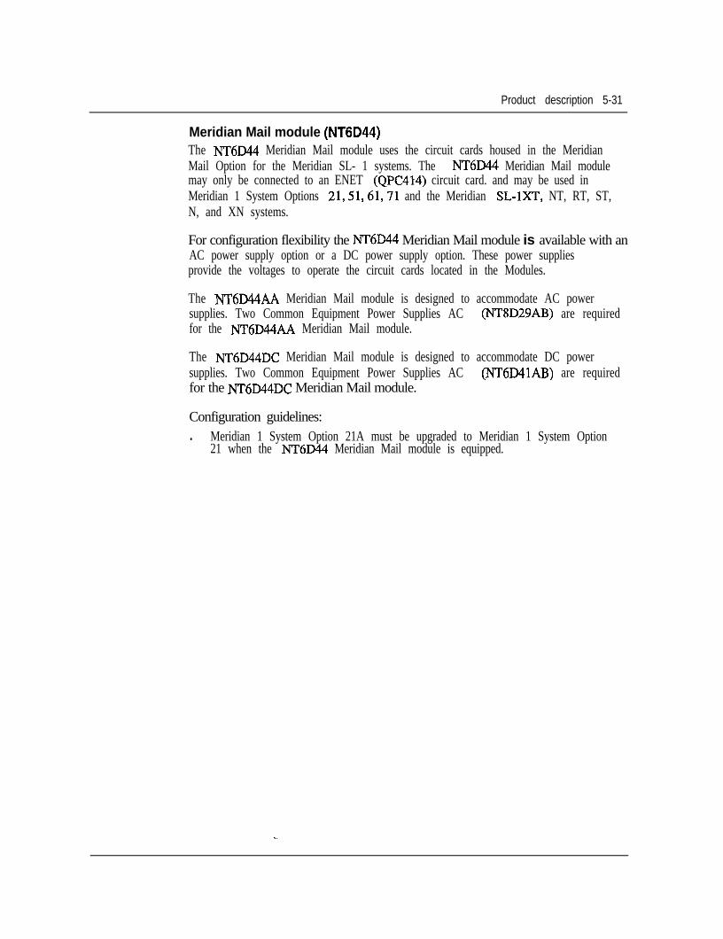
Product description 5-31
Meridian Mail module (NT6D44)The NT6D44 Meridian Mail module uses the circuit cards housed in the MeridianMail Option for the Meridian SL- 1 systems. The NT6D44 Meridian Mail modulemay only be connected to an ENET (QPC414) circuit card. and may be used inMeridian 1 System Options 21,51,61,71 and the Meridian SL-lXT, NT, RT, ST,N, and XN systems.
For configuration flexibility the NT6D44 Meridian Mail module is available with anAC power supply option or a DC power supply option. These power suppliesprovide the voltages to operate the circuit cards located in the Modules.
The NT6D44AA Meridian Mail module is designed to accommodate AC powersupplies. Two Common Equipment Power Supplies AC (NT8D29AB) are requiredfor the NT6D44AA Meridian Mail module.
The NT6D44DC Meridian Mail module is designed to accommodate DC powersupplies. Two Common Equipment Power Supplies AC (NT6D41AB) are requiredfor the NT6D44DC Meridian Mail module.
Configuration guidelines:l Meridian 1 System Option 21A must be upgraded to Meridian 1 System Option
21 when the NT6D44 Meridian Mail module is equipped.
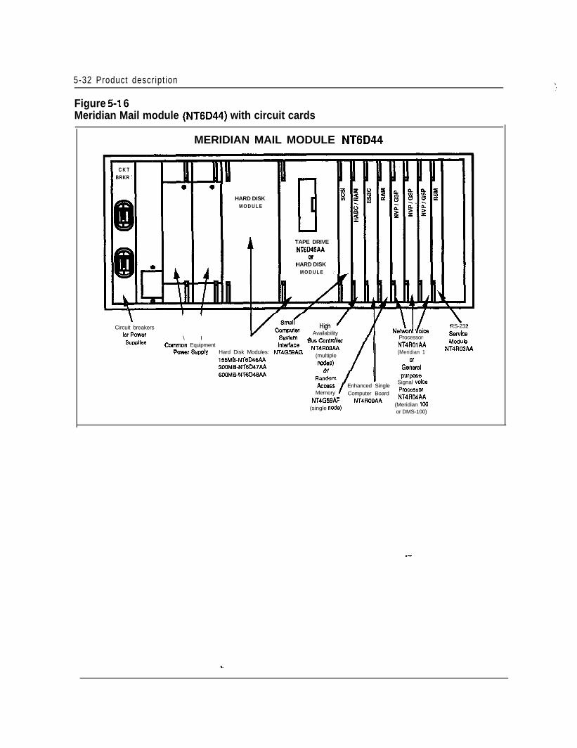
5-32 Product description ‘/.‘,
MERIDIAN MAIL MODULE NT6D44
C K TBRKR
HARD DISKM O D U L E
Figure 5-l 6Meridian Mail module (NT6D44) with circuit cards
\Circuit breakers
for Power \ I
0TAPE DRIVENT6D45AA
orHARD DISK
M O D U L E
High /Availability
n... A-- .-),, e,Ccmmon Equipment
Power Supplylnt&lace yT;;;;;;\n
Hard Disk Modules: NT4G59AG155MB-NT6D46AA
(multiple
3OOMB-NT6M7AAlh?deS.)
n, /
Supplies
6OOMBNT604B44
Processor
RS-232Service
NT4ROlAA(Meridian 1
Or
GSllWll
NT4R03AA
/ Enhanced SingleSignal voice
Memory Computer BoardProcassor
NT4G59AF NT4ROSAANT4RO4AA
(single node)(Meridian 100or DMS-100)
-
Product description 5-33
Miscellaneous equipmentPedestal (NT8D27AB)The NT8D27AB pedestal is a base unit made of die-cast construction and housesthe power distribution unit, system monitor, blower unit, and fan unit connector.
The pedestal is approximately 3 1.5 inches wide by 25.50 inches deep by 10 incheshigh and weighs 30 lbs empty. Leveling feet are provided for up to four tiers, whilea caster option is provided for up to two tiers. Input power for the system is broughtinto and distributed by the pedestal. A Power Distribution Unit located in thepedestal contains an EMI filter and one 30 amp circuit breaker.
One pedestal distributes the input power for one column. Also located in thepedestal are two forced air impellers and a reusable dust filter. The impellers areprotected by two 1 amp circuit breakers.
Configuration guidelines:l One pedestal required per column.
System Monitor (NT8D22AB)The NT8D22AB System Monitor card controls and monitors the status of allpower-related hardware and functions, such as column thermal status, power supplyoperation, blower operation, power fail transfer, circuit breakers, external rectifiers,batteries, and Uninterruptable Power Supply (UPS) systems. The same systemmonitor is used in both AC and DC systems.
One System Monitor is installed in the pedestal of each column. The SystemMonitor located in the column containing the CPU0 Module, acts as the mastersystem monitor while the monitors located in other columns act as slaves. Themaster will poll the slaves and report their status to the CPU. The master SystemMonitor is connected to the CPU by means of an RS232C port located on an SD1card. The slave System Monitors are connected in a daisy chain fashion to themaster by means of an 8-conductor RI type connector and are numbered O-63.
Any power message reported to the CPU by the System Monitor is output to themaintenance TTY. All power messages include the following information: statusor fault indication, hardware type, column number, Module number, and PowerSupply unit number. -
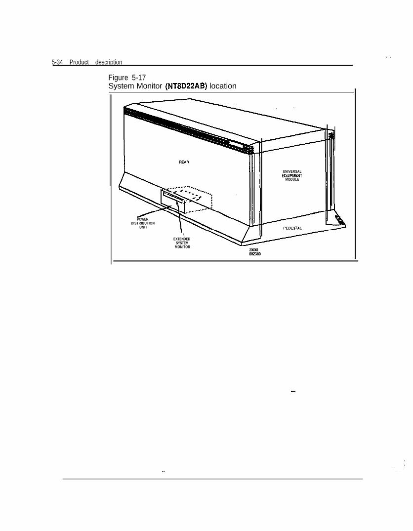
5-34 Product description
Figure 5-17System Monitor (NT8D22AB) location
UNIVERSALEOUIPMENT
MODULE
POWERDISTRIBUTION
UNIT
\ -EXTENDED
SYSTEMMONITOR
206061082366
--
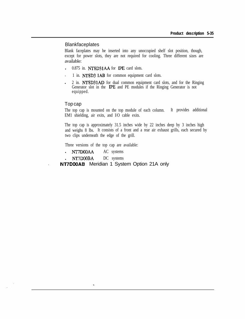
Product description 5-35
Blank faceplatesBlank faceplates may be inserted into any unoccupied shelf slot position, though,except for power slots, they are not required for cooling. Three different sizes areavailable:l 0.875 in. NT8D3lAA for IPE card slots.. 1 in. NT8D3 1AB for common equipment card slots.l 2 in. NT8D31AD for dual common equipment card slots, and for the Ringing
Generator slot in the IPE and PE modules if the Ringing Generator is notequipped.
Top capThe top cap is mounted on the top module of each column. It provides additionalEM1 shielding, air exits, and I/O cable exits.
The top cap is approximately 31.5 inches wide by 22 inches deep by 3 inches highand weighs 8 lbs. It consists of a front and a rear air exhaust grills, each secured bytwo clips underneath the edge of the grill.
Three versions of the top cap are available:l NT7DOOAA AC systemsl NT7DOOBA DC systems
. NT7DOOAB Meridian 1 System Option 21A only
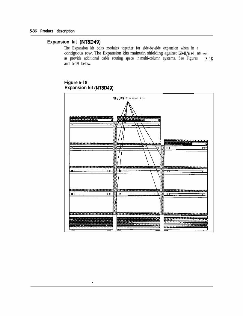
5-36 Product description
Expansion kit (NT8D49)The Expansion kit bolts modules together for side-by-side expansion when in acontiguous row. The Expansion kits maintain shielding against EMI/RFI, as well
as provide additional cable routing space in.multi-column systems. See Figures 5-18and 5-19 below.
Figure 5-l 8Expansion kit (NT8D49)
NT8D49 E x p a n s i o n K i t s
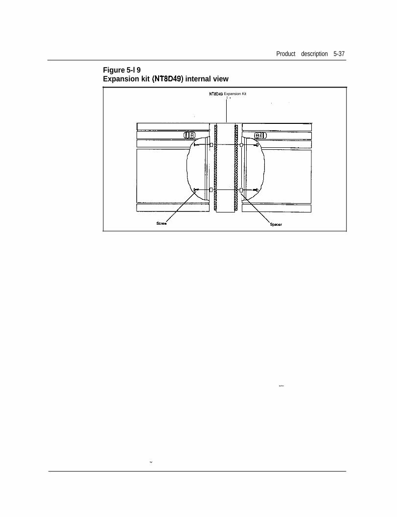
Product description 5-37
Figure 5-l 9Expansion kit (NT8D49) internal view
NT9D49 Expansion KitI -
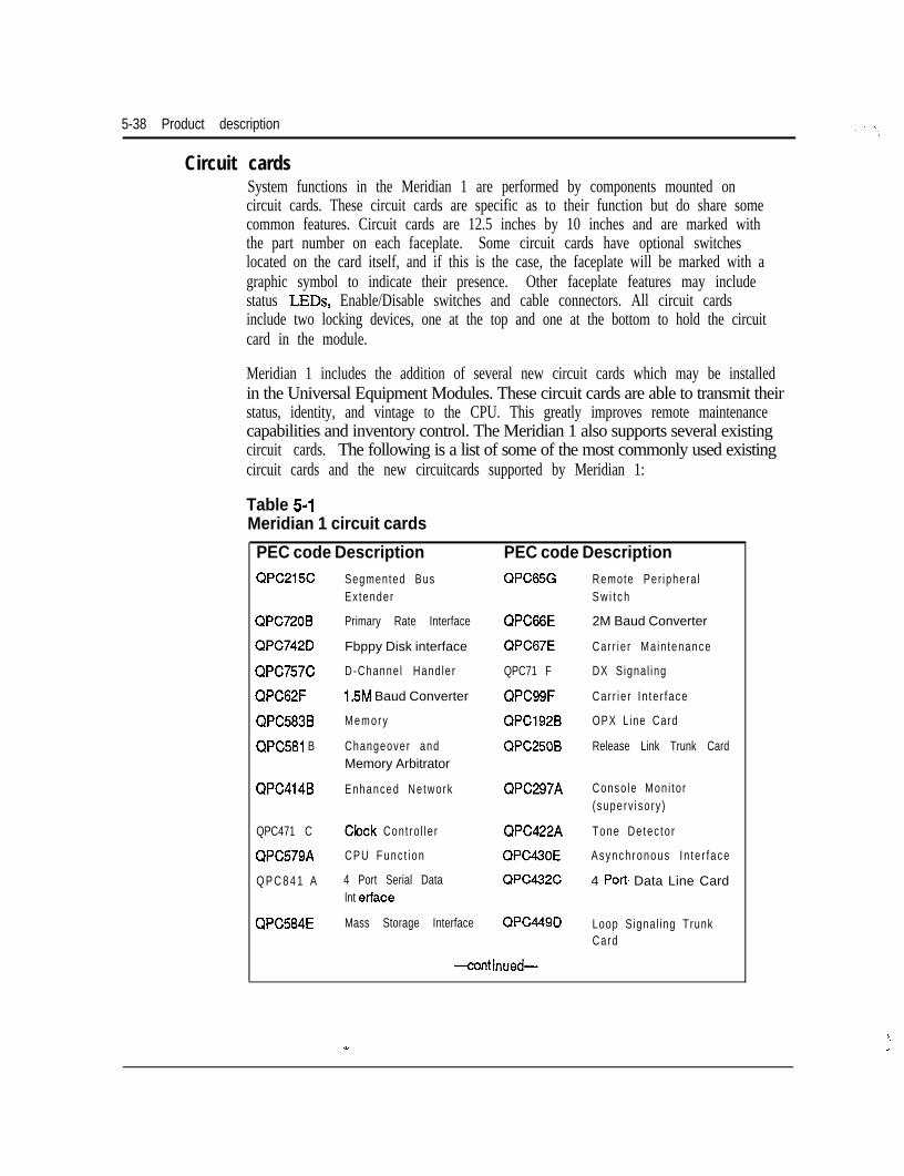
5-38 Product description
Circuit cardsSystem functions in the Meridian 1 are performed by components mounted oncircuit cards. These circuit cards are specific as to their function but do share somecommon features. Circuit cards are 12.5 inches by 10 inches and are marked withthe part number on each faceplate. Some circuit cards have optional switcheslocated on the card itself, and if this is the case, the faceplate will be marked with agraphic symbol to indicate their presence. Other faceplate features may includestatus LEDs, Enable/Disable switches and cable connectors. All circuit cardsinclude two locking devices, one at the top and one at the bottom to hold the circuitcard in the module.
Meridian 1 includes the addition of several new circuit cards which may be installedin the Universal Equipment Modules. These circuit cards are able to transmit theirstatus, identity, and vintage to the CPU. This greatly improves remote maintenancecapabilities and inventory control. The Meridian 1 also supports several existingcircuit cards. The following is a list of some of the most commonly used existingcircuit cards and the new circuitcards supported by Meridian 1:
Table 5-lMeridian 1 circuit cards
PEC code Description PEC code DescriptionQPC215C Segmented Bus QPC65G Remote Per iphera l
Ex tender S w i t c h
QPC720B Primary Rate Interface QPC66E 2M Baud Converter
QPC742D Fbppy Disk interface QPC67E Car r ie r Ma in tenance
QPC757C D-Channe l Hand ler QPC71 F DX Signal ing
QPC62F 1.5M Baud Converter QPC99F Car r i e r I n te r face
QPC583B Memory QPC192B OPX L ine Card
QPC581 B Changeover and QPC250B Release Link Trunk CardMemory Arbitrator
QPC414B Enhanced Network QPC297A Conso le Mon i to r(superv iso ry )
QPC471 C Clock Cont ro l le r QPC422A Tone De tec to r
QPC579A CPU Func t i on QPC430E Asynch ronous In te r face
Q P C 8 4 1 A 4 Port Serial Data QPC432C 4 Port Data Line Cardlnt ertace
QPC584E Mass Storage Interface QPC449D Loop Signal ing TrunkCard
-cant inued-
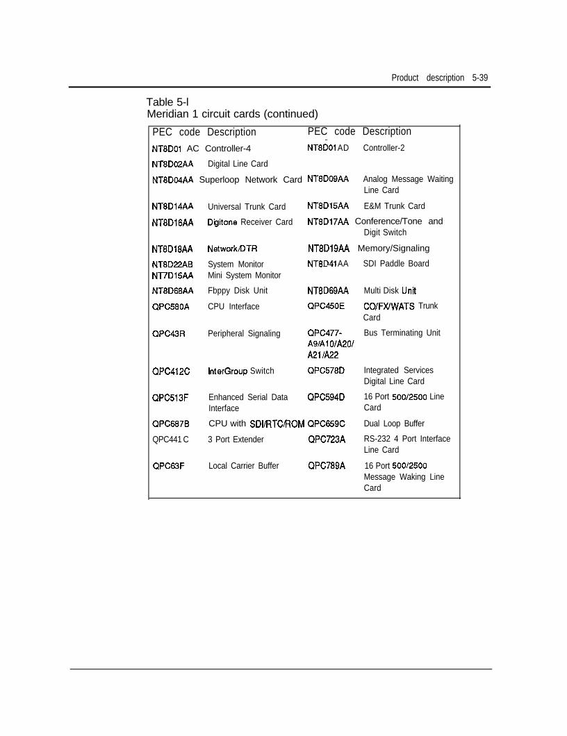
Product description 5-39
Table 5-lMeridian 1 circuit cards (continued)
PEC code Description PEC code DescriptionNT8DOl AC Controller-4 NT8DOl AD Controller-2
NT8D02AA Digital Line Card
NT8DO4AA Superloop Network Card NTBDOSAA Analog Message WaitingLine Card
NT8D14AA Universal Trunk Card NT8D15AA E&M Trunk Card
NT8DlGAA Digitone Receiver Card NT8D17AA Conference/Tone andDigit Switch
NTBDl8AA NetworkDTR NT8DlSAA Memory/Signaling
NT8D22AB System Monitor NT8P41 AA SDI Paddle BoardNT7D15AA Mini System Monitor
NT8D68AA Fbppy Disk Unit NT8D69AA Multi Disk Unit
QPC580A CPU Interface QPC450E COIFXIWATS TrunkCard
QPC43R Peripheral Signaling QPC477- Bus Terminating UnitA9lAl O/A201A21 IA22
QPC412C InterGroup Switch QPC578D Integrated ServicesDigital Line Card
QPC513F Enhanced Serial Data QPC594D 16 Port 500/2500 LineInterface Card
QPC687B CPU with SDIRTCROM QPC659C Dual Loop Buffer
QPC441 C 3 Port Extender QPC723A RS-232 4 Port InterfaceLine Card
QPC63F Local Carrier Buffer QPC789A 16 Port 500/2500Message Waking LineCard
5-40 Product description
Meridian 1 new common equipment circuit cardsFloppy Disk Unit (NT8D68AA)The Floppy Disk Unit (FDU) is used to load the programs and office data into thesystem memory. The FDU contains two 3.-S-inch floppy drives ,and is controlled bythe QPC742 Floppy Disk Interface (FDI). Each floppy d&e has a formattedcapacity of 1.44 MB.
The FDU occupies two adjacent card slots in the CPU, Network, or PE Module. Itis powered through the cable connecting it to the Floppy Disk Interface (FDI).
Configuration guidelines:l One per system.l The FDU can be connected to a maximum of two FDIs.
Multi Disk Unit (NT8D69AA)The Multi Disk Unit (MDU) is used to load the programs and office data into thesystem memory. The MDU contains the following:
l Two 3.5inch floppy drives which are connected to the SCSI interface throughthe SCSI/floppy controller; each drive has a formatted capacity of 1.44 MB
l A 3.5inch hard disk drive which has a built-in SCSI interface and requires aminimum capacity of 20 MB
l An SCSI/Floppy Controller
The MDU occupies three adjacent card slots in the CPU or Network Module andrequires 5V and 12V from the module. The MDU is controlled by the QPC584Mass Storage Interface. The MDU can be connected to a maximum of two MSIs.
Configuration guidelines:. One per system.
Serial Data Interface Paddle Board Z-Port (NT8D41AA)The NT8D41 card is a paddle board that may be installed in the rear of a NT6D39and NT8Dll Module. The NT8D41 card is approximately 12 inches by 4.5 inchesand is similar in appearance to a BTU card. It provides an interface to the CPU forup to two I/O devices.
- -The addressing, (0 - 15) is backwards compatible with the QPC841 SD1 card. Theaddressing is set by address switches and the data rates are; 300,600, 1200,2400,4800 or 9600 bps. The data is transmitted and received as 8-bit serial data with noparity.
Product description 5-41
The number of Serial Data Interface ports required in a system depends on thesoftware options selected by the customer. The following software options requireNT8D41 or QPC841 SD1 ports:. ACD package D (ACD-D)l Auxiliary Processor Link (APL)l Call Detail Recording (CDR) List. Call Detail Recording (CDR) Tape9 Property Management System Interface (PMSI)l System Monitor
Configuration guidelines:. The NT8D41 card does not support the TELETYPE (20 ma current loop)
interface, or 110 baud rate.l It may only be installed in the rear of a NT6D39 or NT8Dll module.. The address of the NT8D41 cannot conflict with existing SD1 addresses.l The valid NT8D41 or QPC841 ports are; 0 - 15.l Two maximum per NT6D39 module.l Three maximum per NT8Dll module. If more than seven ports are required
use the QPC841 card.
Superloop Network card (NT8D04AA)The Superloop Network card employees a new DS30 interface which reduces thenumber of wires required to interface to the NT8D37 Intelligent PE Modules. Thisnew interface is a proprietary DS-30 based format known as DS-30Y and allows theconnection of four 2.56 Mbps loops. The Superloop Network card is connected bya cable to the new Controller card (NTSDOl), located in the NT8D37 Intelligent PEModules, and may be connected to one or two NT8DOl Controller cards overseparate cables.
Provided on the card is a Motorola 68010 microprocessor which is used to controlthe card, and in addition provides new maintenance functionsnot available on theENET card. It receives signaling messages directly from the CPU but will sendsignaling messages to the CPU by means of the Peripheral Signaling card.
The Superloop Network card may be used in conjunction with the ENET card toprovide equivalent network switching functions in existing Meridian SL-1 ST, NT,XT, or RT systems. It provides an interface to four loops on the network businstead of the two loop interface provided by the ENET card. The number of loopsserved by a network shelf or Module remains the same (16), however the SuperloopNetwork frees up additional network card slots which may be used for circuit cards
5-42 Product description
(continued)
that do not require access to the network bus (for example, Serial Data Interface[SDI] or Digital Trunk Interface [DTI] cards). For example: When upgrading aMeridian SL-1 to the new Intelligent Peripheral Equipment a Serial Data Interface(SDI) card may occupy the card slot to the left or the right of the SuperloopNetwork card installed in a Meridian SL-1 enhanced network shelf.
A new overlay program (97) is added to allow the definition a$ configuration ofthe Superloop. New commands are added to existing maintenance diagnostics toallow access to and control of the new maintenance functions provided by theSuperloop Network card.
Configuration guidelines:* Superloop Network cards may be used in existing Meridian SL-1 ST, RT, NT
and XT systems.l 16 networks per enhanced network shelf or module.l When installed in an NT8D35 Network Module, the loop number will always
be an even number (for example 0,4,8, 12,16) and it does not matter if it is theleft or right hand card slot.
l In the NT8D35 Network Module, the odd-numbered network card slots areconsidered left hand and the even-numbered network card slots are right hand.
Conference/Tone and Digit Switch (NT8D17AA)The new ConVI’DS card provides the functionality of the QPC609 Tone and DigitSwitch (TDS) and QPC444 Conference cards on one circuit card and occupies onecard slot on the network shelf backplane or module. One loop is assigned to theconference function and one is assigned to the Tone and Digit and Switch functions.This circuit card interfaces to two ENET loops on the backplane.
The Conf,,DS card contains PROM S that provide 256 tones thus eliminating theneed for special international cards. These new tones may be defined by means of anew overlay program (56) if the FT.C software package is equipped. The tonechoices are downloaded to the card upon initialization. If the FTC software packageis not equipped, then the system will automatically assign normal defaults.
Configuration guidelines: _-
l The Conf/TDS card may be installed in the following existing systems:Meridian SL-1 ST, RT, NT, XT and Meridian 1 System Options 21A, 21,51,61 and 71.
Product description 5-43
Memory/Signaling card (NT8D19AA)The Memory/Signaling card may only be used in the Meridian 1 System Option21A and 21. This card combines the functions of the memory, miscellaneous, andperipheral signaling cards. These cards that were separate functions for the MeridianSL-1 have been combined to reduce the footprint of the Meridian 1 System Option21A and 21.
The memory features include 768K of RAM with error detection and correction.The miscellaneous portion of the card provides the CPU interrupt function and faultmonitoring. The peripheral signaling features include: the signaling interfacebetween the CPU and the peripheral equipment, generation and distribution oftiming signals used by the networks for speech path switching.
Configuration guidelines:. Used only with the NT8Dll CE/PE Module.. One Memory/Signaling card is required per NT8Dll CE/PE Module and it
occupies card slot 3.
NetworWDTR card (NT8D18AA)The Network/DTR card may only be used in the Meridian 1 System Option 21Aand 21. This card combines the functions of the Superloop Network, Controllercard and the Digitone Receiver cards to reduce the footprint of the Meridian 1System Option 21A and 21.
The function of this card is the same as the NT8DOl Controller card, NT8D16Digitone Receiver card, and NT8DO4 Superloop network card which weredescribed previously. The maintenance display function of the NT8DOl Controllercard is not provided.
Configuration guidelines:. The NT8Dll Net/DTR card is always assigned as SuperLoop 28.. One Network/DTR card is required per NT8Dll CE/PR Module.l Use only with the NT8Dll CE/PE Module in card slot 10.
. 8 DTR circuits assigned to virtual card slot 10 of IPE.
5-44 Product description
System Monitor (NT8D22AB)The System Monitor monitors the status of power-related hardware such as columnthermal status, power supplies, fan operation, power fail transfer, circuit breakers,and LEDs. One System Monitor is installed in the pedestal of each column. TheSystem Monitor, located in the column containing the CPU0 Module, acts as themaster system monitor while the system monitors located in other columns act asslaves. The master System Monitor will poll the slave System Monitors and reporttheir status to the CPU. The master System Monitor is connected to the CPU bymeans of an RS-232C port located on an SD1 card. The slave System Monitors areconnected in a daisy chain fashion to the master System Monitor by means of an 8conductor RJ type connector and are numbered O-63.
Any power message reported to the CPU by the System Monitor is output to themaintenance TTY, and power messages include the following information:hardware type, System Monitor number, Module number and Power Supply unitnumber. A system alarm LED is located in the Top Cap (NTSD62) of the columnaffected.
Configuration guidelines:l . The NT8D22AB System Monitor is used in all systems except for the Meridian
1 System Option 21A.
System Monitor - Option 21 A (Nl7DlSAA)The NT7DlSAA System Monitor - Option 21A provides an interface tocommunicate and monitor the CE/PE Power Supply, the CPU, and the thermalswitches. In the event of failure, the System Monitor - Option 21A is notified andthe appropriate alarm is set. A system alarm LED located below the top cap lightsto indicate CPU failure.
Configuration Guidelines:
. The NT7D15AA is used only in the Meridian 1 System Option 21A.
-
Product description 5-45
Intelligent Peripheral Equipment circuit cardsThe Meridian 1 Intelligent Peripheral Equipment circuit cards have been reduced inwidth to only 7/8 inch. These new PE cards have the capability to send specificcard information to the CPU. When asked through a maintenance program, theinformation may contain the PE card (PEC) code and the vintage of that card. Thiswill greatly aid in the inventory and maintenance of a Meridian 1 system.
The Meridian 1 Peripheral Equipment is connected to the Network equipmentthrough the Controller card (NT8DOl) for Intelligent Peripheral EquipmentModules (NT8D37), or the Peripheral Buffer (BUF), for the Peripheral EquipmentModules (NT8D13). Controller circuit cards (NT8DOl) are used with SuperloopNetwork circuit cards, while Peripheral Buffer cards are used with ENET circuitcards. The two circuit cards serve basically the same function, that is theconnection point for shelf/module to network communications. The NT8DOlhowever does have some additional maintenance capabilities that the PeripheralBuffer does not have, such as a maintenance status display on the faceplate.
Controller Card (NT8DOl)The Controller card provides the primary interface and control functions betweenthe SuperLoop Network and up to 16 Meridian 1 Intelligent PE cards. It will switchPCM voice and data from the DS-30X loops of the SuperLoop Network to the DS-30Y loops of the PE cards.
The card is installed in the NT8D37 IPE Module and interfaces to the SuperLoopnetwork card by means of a cable. The NT8DOl circuit card consists of amother/daughter assembly which is installed in a dedicated card slot marked“CONT” in the center of the NT8D37 IPE Module.
Located on the NT8DOl card is a Motorola 68010 microprocessor which is used forcontrol functions, message format conversions (DS-30X loop to DS-30Y loop), andto perform new maintenance functions. A maintenance display located on thefaceplate of the NT8DOl card will indicate the status of the card. One NT8DOlcard is required per NT8D37 IPE Module. The NT8DOl may only be connected toa SuperLoop Network card and cannot be installed in the NT8D13 IPE Module.
The NT8DOl is available in two configurations: Controller-2 (Cont-2) andController-4 (Cont-4). _-
The Cont-2 allows the connection of up to two SuperLoop Network cards to asingle module, while the Cont-4 allows the connection of up to four SuperloopNetwork cards to a single module.
5-46 Product description
(Continued)
Once connected to the NT8DO1, the Intelligent PE Module is divided into logicalsegments. Each segment consists of four PE circuit card slots. These segments arenumbered O-3. Segment 0 consists of PE slots O-3, segment 1 consists of card slots4-7, segment 2 consists of card slots 8-l 1, and segment 3 consists of card slots 12-1 5 .
One Superloop Network card maybe assigned from one to eight segments on one ortwo NT8D37 Intelligent PE Modules. Several different SuperLoop to segmentarrangements are possible. The following figure shows the possible SuperloopNetwork to Controller card configurations. The Superloop Network to Controllercard configuration chosen will depend upon system traffic requirements andhardware usage.
Controller card configuration information is.entered in Overlay 97. This programallows for the assignment of Controller card numbers (l-95) and the Controller cardlocation codes. Both of these parameters are used to identify the location of theController card.
Configuration guidelines:l The Controller-4 card is used when you assign more than two Superloops per
module. (For high traffic conditions or Non-blocking requirements).. The Controller-2 card is used in all other configurations.
Digital Line Card (NT8D02AA)The Digital Line card may be installed in an NT8D37 IPE or NT8Dll CE/PEmodule only and interface up to 16 M2000 series or M3000 digital telephones. Itprovides 16 voice and 16 data ports which allows any set connected to transmitvoice and data simultaneously over one pair of wires.
Configuration guidelines:l One per 16 digital terminals.l Used only with the NT8D37 Intelligent PE Module or NT8Dll CE/PE Module.
U.

Product description 5-47
Analog Line Cards (NT8BO3AA I NT8DOSAA)
. Analog Line NT8D03AA
. Analog Message Waiting Line Cards NT8D09AA
The Analog Line Card and the Analog Message Waiting Line Cards may beinstalled in NT8D37 and NT8Dll Modules only. Both the Analog Line Card andthe Analog Message Waiting Line Card interfaces up to sixteen 500 or 2500 typesets and performs analog-to-digital and digital-to-analog conversion.
The Analog Message Waiting Line Card will additionally provide the interface tothe -150 V supply to light Message Waiting lamps located on the sets connected tothe card.
Configuration guidelines:. Used only with the NT8D37 Intelligent PE Module or NT8Dll CE/PE Module.
Universal Trunk Card (NT8D14AA)The Universal Trunk card may be installed in a NT8D37 or NT8Dll Module onlyand provides the interface to the following types of trunk circuits:l Central Office (CO, FAX, WATS, Japan CO) - loop or ground start9 2-way TIE trunk - loop dial repeating or automatic incoming dial. Direct Inward Dial (DID)l Paging Equipmentl Recorded Announcement equipment. Music Equipment
The UniversalTrunk card interfaces up to eight of the previously mentioned trunkcircuits. It will also support A- law and p-law operations as defined in the system’sconfiguration record. New prompts have been added to Overlay Programs 14 and16 to allow the configuration of the Universal Trunk card.
-
5-48 Product description
(Continued)Configuration guidelines:. One required for every eight of the above listed trunk types.. Used only with the NT8D37 Intelligent PE Module or ,W8Dll CE/PE Module.
E&M Trunk Card (NT8D15AA)The E&M Trunk card interfaces up to four trunk circuits. It will also support A-lawand p-law operations as defined in the system’s configuration record. New promptsare added to Overlay Programs 14 and 16 which will allow the configuration of theUniversal Trunk card.The E&M Trunk card may only be installed in the NT8D37 Intelligent PeripheralEquipment Module or the NT8Dll Common/Peripheral Equipment Module andprovides the interface to the following types of trunk circuits:
l 2-wireE&Ml 4-wire E &Ml 4-wire DXl Paging Equipmentl Dictation Equipment
Configuration guidelines:. Used only with the NT8D37 Intelligent PE Module or NT8Dll CE/PE Module.
DigitoneTM Receiver (NT8D16AA)The Digitone Receiver card provides a total of eight channels of Dual Tone MultiFrequency (DTMF) or Multi Frequency @IF) detection and it may be installed inany card slot in an NT8D37 or NT8Dll Module. An overlay program is used todetermine the function of the card.
Configuration guidelines:. Required when 2500 sets, Digitone DID trunks, Digitone-Tie trunks or DISA
used.l Used only with the NT8D37 Intelligent PE Module or NT8Dll CE/PE Module.
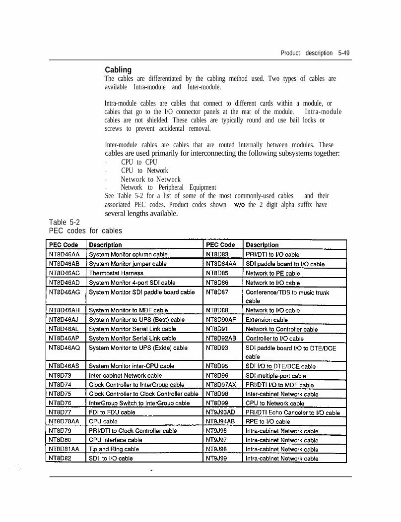
Product description 5-49
CablingThe cables are differentiated by the cabling method used. Two types of cables areavailable Intra-module and Inter-module.
Intra-module cables are cables that connect to different cards within a module, orcables that go to the I/O connector panels at the rear of the module. Intra-modulecables are not shielded. These cables are typically round and use bail locks orscrews to prevent accidental removal.
Table 5-2PEC codes for cables
Inter-module cables are cables that are routed internally between modules. Thesecables are used primarily for interconnecting the following subsystems together:. CPU to CPU. CPU to Network. Network to Network. Network to Peripheral EquipmentSee Table 5-2 for a list of some of the most commonly-used cables and theirassociated PEC codes. Product codes shown w/o the 2 digit alpha suffix haveseveral lengths available.
5-50 Product description
Software descriptionThe Meridian 1 Superloop and Intelligent Peripheral Equipment is supported onX11 release 15 and future Xl 1 Releases. The Meridian 1 System Option 21A and21 is supported by software generic ” 1011”; System Options 5 1 ,and 6 1 by softwaregeneric “1111” and System Option 71 by software generic “1211”. In addition,three new software options are introduced to provide the extended configurationcapabilities required by the new hardware.
These options are:l Software Option 203 (see Note 1)
Allows the configuration of Superloops and Intelligent Peripheral Equipment.This option is applicable to all System Options and to Meridian SL-1 systemsextended to use Superloops and Intelligent Peripheral Equipment.
0 Software Option 204 (See Note 2)
Allows the configuration of the combined Conference/Tone and Digit card,Nl&8F;AA. Applies to all System Options and Meridian SL-1 systems using
l Software Option 205 (See Notes 1 and 2)
Provides the configuration overlay LD97. Required for Software Options 203and 204.
Note 7: Any system using Superloops and Intelligent Peripheral Equipmentrequires Software Options 203 and 205.
Note 2: Any system using the new Conference/Tone & Digit card(NT8D17AA) requires Software Options 204 and 205.
Software downloadThe new circuit cards introduced with the Meridian 1 System Options takeadvantage of the benefits offered by distributed processing, enabling significantsavings in CPU real time to be realized while maintaining compatibility withexisting Meridian SL-1 Systems (the real time savings do not apply to existingMeridian SL-1 Systems unless Superloops and Intelligent Peripheral Equipment areused).
-The new Superloop network card, the Controller-2 and Controller-4 cards, andIntelligent Peripheral cards contain microprocessors to provide the off-loading ofwork that was previously done by the CPU and the flexibility to change parameterswithout hardware revisions. The opportunity has also been taken to significantlyincrease the self diagnostic and system diagnostic capabilities through use of the on-board microprocessors, resulting in improvements in maintainability.
Product description 5-51
(Continued)
This flexibility is achieved through software downloading. The program store forthe processors contained on the new cards is stored on the new 3.5inch floppydiskettes or on the hard disk drive and is downloaded to the pack (in broadcastmode) following a system reload (sysload) or optionally by means of an overlayprogram command. Thus, downloadable software upgrades are possible without theneed to reload the system and, in the event that similar Intelligent Peripherals havedifferent requirements, selective upgrades are possible. _
Typical CPU functions relieved by this capability are the handling of telephone setringing, which takes place on the Controller card and Dial pulse digit collection,handled by the Intelligent Peripheral cards. The Peripheral Signaling Card isbypassed, since all CPU output signaling messages are handled directly by theSuperloop network card, avoiding a potential bottleneck, significantly enhancingmessage handling. Whenever possible, hardware switch selection on these cardshas been removed and the on-board microprocessors allow the soft selection ofoptions.
These new cards make further use of this intelligence by being capable of reporting,following a command from Overlay 32, their pack Product Code, serial number,release number, and manufacture location, greatly assisting inventory control andmaintenance. Another capability, that of reporting the presence of a card andfunction following insertion in the Module, is achieved through the Controller-2 andController-4 card continually scanning the module for such events (also applies ifcard is removed; its absence is reported).
Configuration extensionsSince the new Intelligent Peripheral Equipment extends the number of Peripheralcircuit cards per shelf from 10 to 16 (card slots O-15) and the number of TNs percard has increased from 16 to 32, all overlay programs relating to the provisioningof peripheral equipment have been modified to allow for these expanded parameters(within the constraints of currently available circuit card densities).
In addition, a new overlay (LD97) is introduced which provides for the definition ofIntelligent Peripheral Equipment system parameters (such as companding law forcodecs, maintenance threshold levels, peripheral software download options orswitchhook flash timers), and the configuration of the new Superloop networkcards, Intelligent Peripheral Equipment controller cards, the combinedConferenceflone and Digit Switch card and the combined Superloop and Digitonereceiver card.
5-52 Product description
Maintenance enhancementsMaintenance diagnostic Overlays 30,32, and 45 have undergone significantrevision and extension to exploit the capabilities’of the Superloop network card,Controller card and Intelligent Peripheral Equipment cards. In addition to thegreatly enhanced self diagnostic abilities (due to the on-board microprocessors),expanded commands within these overlays provide improved, easy to use manualtesting and trouble shooting tools to the craftsman, enabling rapid identification oftrouble areas and faulty hardware.
Test capabilities include:l Testing the timeswitch memory on the Superloop network cardl Generation of test patterns to test different segments of the system:
- Superloop Network to Controller- Superloop Network to Superloop Network- Controller to Superloop Network- Controller to Controller- Superloop Network to self through backplane, Controller terminal or
Controller and terminal- Controller to self through terminal- Controller or Superloop Network to self through special test channel
l Interrogation of cards to reveal function, release, serial number and manufacturelocation code
l Interrogation of digital telephone sets to reveal type, code, color and release
Overlay 45 (The background signalling diagnostic program) now providesimproved test progress information to the craftsperson and is able to identify andreport the card requiring replacement following the detection of a fault. Also, if theprogram is interrupted, it will restart where it was interrupted.
ConversionAutomatic in-line conversion allows upgrading to release 15 from release 12 andbeyond. Reconfiguration of the data structures occurs during the SYSLOADsequence to take account of changes made to accommodate new features. To assistwith the reconfiguration of terminal equipment to the new Superloops, overlay 25has been modified to allow TNs on single, double, and quad density peripheralequipment to be moved to Superloops.
Product description 5-53
Terminal equipmentTo the user, the telephone is the most visible part of the business communicationssystem. Meridian1 systems support a wide range of telephones, including multilineand single line telephones, as well as digital sets with key and display functions anddata transmission capabilities. A range of options for attendant call processing andmessage center applications is also available. In addition, a number of other add-ondevices are available to extend and enhance the features of telephones and consoles.Add-on devices include key/lamp modules, lamp field arrays, handsets, andhandsfree units.
Digital TelephonesAnalog-to-digital conversion takes place in the set itself rather than in the associatedperipheral line card. This eliminates attenuation, distortion, and noise generatedover telephone lines, and results in a voice quality that is exceptionally clear andcrisp. Signaling and control functions are also handled digitally. An eight-bitmicroprocessor in the telephone set monitors all keypad and hookswitch operationsand sends messages to communicate to the system any change in status. Lampindications, ringing, and handsfree operation are controlled by messages sent fromthe system to the telephone set.
Time Compression Multiplexing (TCM) is used to integrate the voice, data, andsignaling information over a single pair of telephone wires. TCM compresses thecontinuous bit stream between the system and digital set into bursts and leavessufficient space between bursts for data to be received without interference from thefar end: the system sends one burst of 20 data bits to the digital set; the set processesthe bits and sends a similar burst back to the system. This cycle is repeated 8000times per second. Every transmitted burst is compressed into two 64 Kbps trafficchannels plus two 16 Kbps signalling channels. This technique, often referred to as“ping-pang” transmission, provides a total bandwidth of 5 12 Kbps.
For applications where data communications is required, Meridian 1 digitaltelephones offer an integrated data option that can be field installed to providesimultaneous voice and data communications over single pair wiring to a port on adigital line card. The Asynchronous Data Option provides data communications atspeeds up to 19,200 bits per second from an ASCII terminal or desktop computer.Data calls are performed entirely from the data terminal keyboard. Other featuressuch as Speed Calling and King Again (which notifies the user when a busycomputer port is free) are selected from a menu displayed onthe terminal screen.The data option hardware is placed inside the telephone and uses the same pair ofwires used for voice calls.
5-54 Product description . . - 1
Meridian Digital Telephones
M2006 - Single Line TelephoneThe Meridian 1 M2006 digital telepho?e provides six programmable keys.Key zero (‘0’) functions as the directory number key, and the five remainingkeys are programmable for software feature access. The M2006 comesstandard with on-hook dialing, message waiting LED, Hold/Release Keys, andindependent volume/tone controls. The set also accepts the new ProgrammableData Adapter and External Alerter Interface options. Both of these optionsrequire an external power source.M2008 Multi-line TelephoneThe Meridian M2008 digital set is equipped with eight keys which can beprogrammed for any combination of directory numbers or software features.The set comes standard with on-hook dialing, Message waiting LED,Hold/Release keys, and independent volume/tone control. The M2008 can alsobe equipped with an optional 2x24 alphanumeric LCD display, and it acceptsthe new Programmable Data Adapter and External Alerter Interface options.All add-on options require an external power source.
M2616 Multi-Line TelephoneThe M2616 digital set has 16 programmable keys for any combination ofdirectory number and software feature assignments. It also comes standard withon-hook dialing, message waiting LED, Hold/Release keys, independentvolume control, and two-way handsfree capability. (Note that the handsfreefunction on the M2616 is unique in that it is software assignable.) Also, theM2616 accepts the new 2x24 alphanumeric LCD display module,accommodates up to two 22-key Meridian Key Expansion Modules, and can beconfigured with Programmable Data Adapter and External Alerter Interface.M2016S Secure TelephoneThe M2016S is a secure digital telephone, meeting the security requirement forClass-2 as described by TSG (Telephone Security Group) standards. The sethas 16 keys which can be programmed for any combination of directorynumbers or software features. It comes standard with on-hook dialing, messagewaitinglsecure status LED, Hold/Release keys, and independent volume/tonecontrol. The M2016S can also be equipped with an optional 2x24 alphanumericLCD display, key expansion module, and it accepts the Programmable DataAdapter option. This set requires an external power source.M2216ACD TelephonesThere are two versions of the M22 16ACD set: M22 16ACD-1 and M2216ACD-2. Optimized for ACD environments, these 16-key programmable multi-linesets come standard with a 2x24 alphanumeric display, on-hook dialing, messagewaiting LED, Hold/Release keys, independent volume control, and dual headsetjacks, one of which can be user optioned at the set level for ‘talk/listen’ onlysupervisor monitoring. and one PJ-327 jack to accommodate standard carbonheadsets. For those applications requiring handset operation, the TELADAPTjacks on Model -1 have an interface option which provides the electricalproperties required to use a DKS handset. The PJ-327 jack on Model-2 canaccommodate a carbon handset.
Product description 5-55
(continued)The M2216ACD sets also accommodate up to two, 22-key Meridian Keyexpansion Modules, and can be equipped with the Programmable Data Adapterand External Alerter Interface options. The Model-l set is loop powered forthe Display option only. The Model-2 set requires an. external power source forall options.
M2317 - provides 11 programmable keys for any combination of features anddirectory numbers, 5 context sensitive softkeys, handsfree conversationcapability and a 2 line-by-40-character alphanumeric display. Release and Holdkeys are color coded as are changeable key caps to distinguish lines fromfeatures. Large LCDs for each key provide a distinctive indication of call statusand feature activation. A built-in speaker permits the user to leave the handsetin place until the called party is on the line.Meridian M3000 TouchphoneThe M3000 Touchphone is a digital telephone which provides completecommunications control by means of a unique touch-sensitive liquid crystaldisplay. It provides access to the full complement of calling features to meetthe demanding requirements of business decision-makers. The LCD screenindicates which features can be used at any given time and a feature labelled“Explain” provides access to a built-in user guide.The Meridian Touchphone is equipped with a full list of standard features. Sixlines can be configured as directory numbers, private lines, and intercoms.Handsfree with automatic answerback is built-in. A private Directory of over100 names and numbers permits the dialing of voice, data, and intercom calls bysimply touching a name on the LCD screen.
Display ModuleThe Display Module available as an option with the M2008, M2616 andM2016S is a 2 line by 24 character liquid crystal display by which can displaythe name and extension of callers from within the system or network. Itsimplifies feature use with interactive prompts and messages in either Englishor French.A second version of the 2x24 LCD display presents ACD screen information.The ACD Display Module can be added to the M2008, M2616, or M2016S setsfor use in an ACD environment. (Note that this display comes standard on theM2216ACD.) Also, the ACD Display Module is available in six languages:English, French-European, French-Canadian, Dutch, Spanish, and German.
--
5-56 Product description
Meridian Key Expansion ModuleThe Meridian Key Expansion Module is a modular 22-key unit which connectsto the M2216, M2016S and M2216ACD sets, providing access to 22 additionalkey/lamp pairs for access to directory numbers and/or software features. Eachkey has an associated LCD indicator for call status and feature activationinformation. A maximum of two Key Expansion Modules can be added per set.The module is connected electrically to the set via a ribbon connector, andmounts physically on the set’s footstand base. The footstand must be orderedseparately and is available in two versions:
l Footstand-one accommodates a 38-key configuration (16 button setplus one key module)
l Footstand-two accommodates a 60-key configuration (16 buttonset plus two key modules)
Programmable Data AdapterThe Meridian Programmable Data Adapter (MPDA) is a new asynchronousdata card which fits into a slot in the base of the M2006, M2008, M2616,M2016S, and M2216ACD sets. Any ASCII terminal, PC, or Macintosh canthen be directly connected to the telephone via the built-in RS232 interface.Data capability is provided by the MPDA, working in conjunction with thedigital interface chip residing in the telephone.Data calls can be placed from the telephone keypad, via keyboard dialing, orusing the ‘AT command’ dialing feature. Two primary enhancements of thenew data adapter are the addition of Script file capability and enhancedHAYESTM ‘AT command’ support.Additional data features supported are:
l asynchronous transmission at 19,200 bpsl data call origination and termination via keyboard dialing, AT
dialing, and keypad dialing.. Speed call capabilityl Modem Pool calling
External Alerter InterfaceThe External Alerter Interface module provides a connection interface tostandard remote alerting devices.
Power Supply BoardThe Power Supply Board is a printed circuit board (PCB)which mounts insidethe telephone and receives its power from either a 1 HI/220 volt wall-mounttransformer or closet power supply. the plug-in transformer is single winding,and is equipped with a 10 foot cord of 22AWG two-conductor stranded andtwisted wire with a modular duplex adapter.
Product description 5-57
Other Digital Telephones
M2009 - provides the benefits of multiple lines and feature flexibility withnine programmable keys.M2112 - has a built-in handsfree capability and provides eleven feature keyswhich can be assigned in any combination of lines and features. The 12th keyis the HandsfreelMute key.M2018 - offers 18 keys for the additional lines and features required ifi typicalsecretarial environments.
Attendant ConsolesThe Ml250 and M2250 attendant consoles incorporate design improvements basedon the QCW4E Attendant Console, and are functionally compatible with theQCW4. The Ml250 is driven and powered by SL-1 line cards and is compatiblewith QCW4 console cabling schemes. The M2250, a digital version of the Ml250with additional features and display options, is driven and powered by a digital linecard and has a modified cabling scheme.
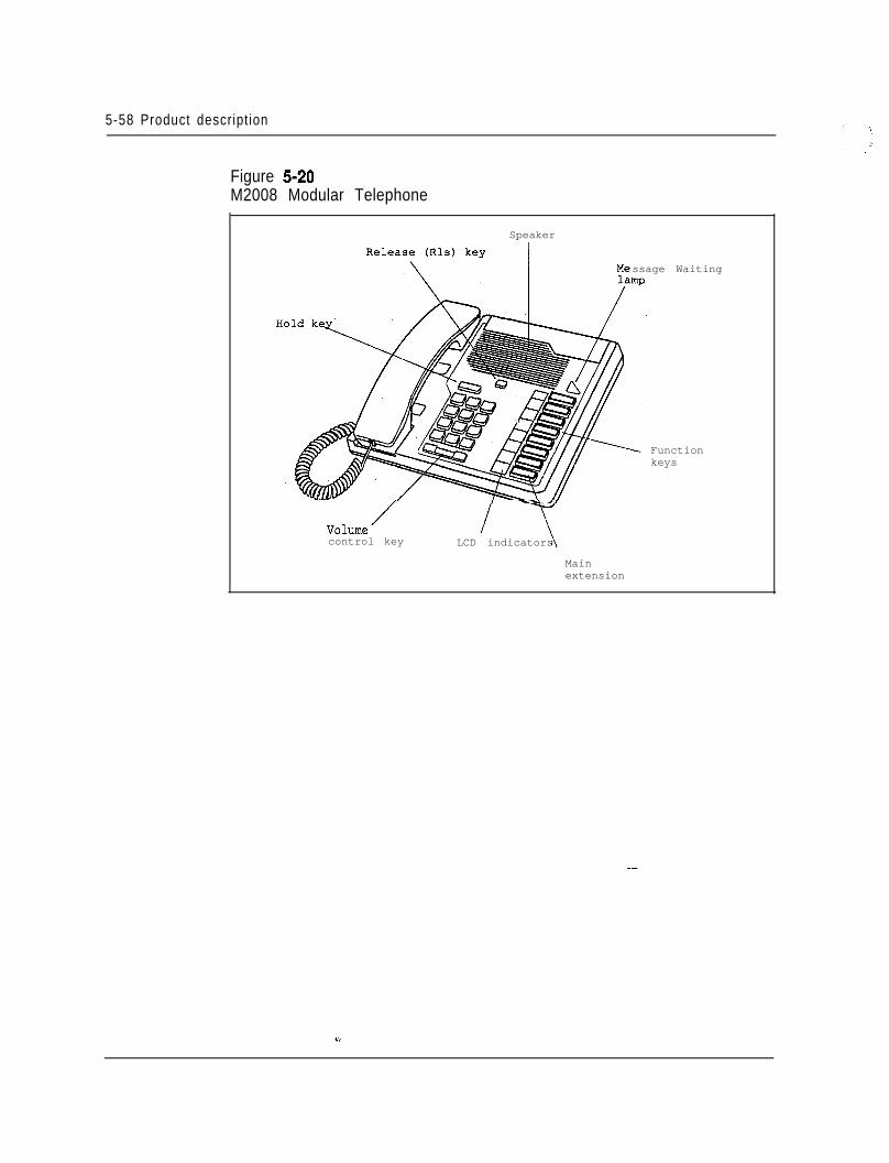
5-58 Product description
Figure 5-20M2008 Modular Telephone
Speaker
ssage Waiting
Functionkeys
V0lUlle /
control key LCD indicators
Mainextension
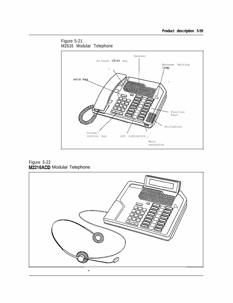
Product description 5-59
Figure 5-21M2616 Modular Telephone
Re
Speaker
lease (Rls) key
\Message Waiting
Functionkeys
' Microphone
Volume' /control key LCD indicators \
Mainextension
Figure 5-22M2216ACD Modular Telephone
5-60 Product descript ion
Power equipmentAC power distribution
The internal AC power system consists of the following main elements:l Pedestal Power Distribution Unit (PDU). Module to Module Power Harnessl Module Power Distribution Unit (MPDU)9 AC Power Supplies
The AC line cord enters the Pedestal and connects to a terminal block located in thePDU. From the terminal block, the AC voltage passes through a line filter and amain Column circuit breaker, which provides power to the four modules and theBlower Unit. The System Monitor runs off a small AC power supply in the PDU.The module to module harnesses distribute AC power to each module by means ofthe MPDUs, which contain circuit breakers for safe operation and easymaintenance.
There are three different AC power supplies that provide power to the commonequipment, peripheral equipment, and combined common/peripheral equipmentmodules. In addition, there is a ringing generator that provides AC ringing (andmessage waiting lamp voltages) when required for the peripheral equipmentmodules.
There are no additional external power components required for AC-poweredsystems. Reserve power, if needed, is accomplished through the use of an externalUninterruptible Power Supply (UPS).
DC power distributionThe internal DC power system consists of the following main elements:l Pedestal Power Distribution Unit (PDU). Module to Module Power Harnessl DC Power Converters
The power cables enter the Pedestal and connect to an internal terminal blocklocated beneath the PDU. From there, the DC voltage enters the PDU, which hasfive circuit breakers - one for each module and one for the Blower Unit. TheSystem Monitor runs off a small DC-DC converter in the PDU. The module tomodule harnesses distribute DC power directly to the DC-power converters in eachmodule, which contain on/off switches for easy maintenance. Circuit breakerprotection is provided in the Pedestal.
Product description 5-61
(Continued)
There are three different DC power converters that provide power to all of thecommon equipment, peripheral equipment, and combined common/peripheralequipment modules, as well as a ringing generator that provides AC ringing (andmessage waiting lamp voltages) when required for the peripheral equipmentmodules.
AC RectifiersThe external portion of DC-powered systems is generally referred to as the “powerplant”, and consists of the rectifiers and distribution equipment, as well as reservebatteries if required.
For Meridian 1 System Options 2 1,5 1, and 6 1, Northern Telecom offers a powerplant based on the NT6D52AA Rectifier, with an output capacity of 30A perrectifier. For systems with power requirements of up to 90A, up to 3 rectifiers arecontained in a 4’6” open relay rack and are joined together with a wall-mountrectifier/battery connection and distribution box (QBLlS). This configuration isgenerally adequate to power 2 full columns of 8 modules. For expansion, a secondQBLl5 may be added, with up to 3 additional rectifiers in a 2nd rack.
For System Option 71, as well as larger System Option 61 configurations, Northernoffers the QCA 13 power plant based on the NT5C03B J Rectifier, with an outputcapacity of 50A per rectifier. Up to 4 rectifers are contained in the prime cabinetfor a total of 200A. A supplemental power cabinet holds 4 additional rectifiers, anda 2nd supplemental cabinet holds 2 rectifiers, for a total of 10 rectifiers and a totalQCA13 system capacity 500 A.
Customer-provided power is an option for all Meridian 1 systems. The QBL12Battery Distribution Box is usedto connect a wide variety of power equipment to thesystem. In addition to serving as an interface point between the NT-suppliedMeridian 1 and the customer-supplied power equipment, the wall-mounted QBL12provides positive and negative busbars for input rectifier connections and up to 24fused 30A outputs to feed up to 12 columns of equipment, as well as monitoringand reporting capabilities.
For more detailed information on the Meridian 1 power equipment andprovisioning, see NTP 553-3001-152, Power Engineering.
- -
U.

5-62 Product description
_-
-*;;,f
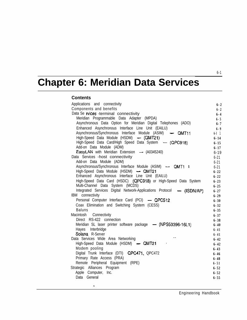
6-1
Chapter 6: Meridian Data ServicesContentsApplications and connectivityComponents and benefitsData Se r-vices -terminal connectivity
Meridian Programmable Data Adapter (MPDA)Asynchronous Data Option for Meridian Digital Telephones (ADO)Enhanced Asynchronous Interface Line Unit (EAILU)Asynchronous/Synchronous Interface Module (ASIM) - QMTllHigh-Speed Data Module (HSDM) - (QMT21)High-Speed Data Card/High Speed Data System - (QPC918)Add-on Data Module (ADM)EasyLAN with Meridian Extension - (A0345240)
Data Services -host connectivityAdd-on Data Module (ADM)Asynchronous/Synchronous Interface Module (ASIM) - QMTl 1High-Speed Data Module (HSDM) - QMT21Enhanced Asynchronous Interface Line Unit (EAILU)High-Speed Data Card (HSDC) (QPC918) or High-Speed Data SystemMulti-Channel Data System (MCDS)Integrated Services Digital Network-Applications Protocol - (ISDN/AP)
IBM connectivityPersonal Computer Interface Card (PCI) - QPC512Coax Elimination and Switching System (CESS)Baluns
Macintosh ConnectivityDirect RS-422 connectionMeridian SL laser printer software package - (NPS50396-16Ll)Hayes InterbridgeSolana R-Server
Data Services Wide Area NetworkingHigh-Speed Data Module (HSDM) - QMT21Modem pooling
--’
Digital Trunk Interface (DTI) QPC471, QPC472Primary Rate Access (PRA)Remote Peripheral Equipment (RPE)
Strategic Alliances ProgramApple Computer, Inc.Data General
6-26-26-46-56-76-9
6-l 16-146-156-176-196-216-216-216-226-226-236-256-276-296-306-326-356-376-386-406-416-416-426-426-436-466-486-516-526-526-55
Engineering Handbook
6-2 Meridian Data Services
Digital Equipment CorporationHewlett-Packard CompanyNCRPrime Computer, Inc.Unisys (Sperry)Wang Laboratories Inc.
Data Services applicationsBanking industry application - Regional Bank NetworkUniversity application - Eastern College NetworkAerospace industry application - defense contractorComputer industry application -workstation manufacturer
Third party compatibility testing programData products and product codes
.
6-576-596-616-636-656-676-696-696-716-736-756-766-78
Applications and connectivityThe architecture of the Meridian 1 SL-1 Private Branch Exchange (PBX) wasspecifically developed to accommodate the rapidly expanding requirements for dataas well as voice communications. Since its introduction, the SL-1 product line hasevolved and improved to include a wide portfolio of data communicationscapabilities.
Northern Telecom is serving today’s demands for data connectivity without causingits huge installed base of PBX systems to become obsolete. Old and new, allsystems are able to take advantage of the full family of data product offerings.
FlexibilityNorthern Telecom’s commitment to OPEN World (Open Protocol EnhancedNetworks) ensures that customers will always be able to achieve maximumfunctionality and compatibility in data processing and data communications,especially in multi-vendor environments. A single terminal can access multiplehosts, networks, and applications.
Meridian Data Services is a family of hardware and software products that attachpersonal computers, terminals, host computers, and other data communicationsdevices to Northern Telecom’s Meridian 1digitalPBX. Data Services productsenable a PC or terminal device to communicate, through the Meridian 1, tocomputers, Local Area Networks (LANs), printers, host computers and otherresources via standard telephone wiring.
- -Included in this Chapter are all of the products from MeridianData Services -products that can help efficiently manage resources and allow for easier, faster andmore convenient access to information.
Components and benefitsMeridian Data Services provides a comprehensive group of products that connectyour data devices to the same telephone wiring you have installed for your MeridianDigital Telephones. In this manner, Meridian Data Services provides you with
Engineering Handbook
Meridian Data Services 6-3
multiple host access, direct connectivity, efficient resource management, portcontention, increased distance, easier moves and changes, and improved data callhandling. Meridian Data Services provide the following advantages.
Multiple host accessMeridian Data Services provides broad connectivity which allows users to accessmultiple networks, applications, and hosts from a single terminal. This eliminatesthe need for multiple terminals on a desk and redundant networks.
Direct connectivityMeridian Data Services has the unique advantage of providing direct connectionswithout the use of data modules for ASCII terminals, PCs, Macintosh computers,protocol converters, modems, X.25 PADS and many different computers. The resultis reduced costs.
Efficient resource managementThere are tremendous advantages in using a single unified system for both voiceand data communications.
Perhaps the most obvious benefit is the inherent efficiency of managing resources aspart of one system. Resources such as cabling, transmission lines, host computerports, terminals, personal computers, and peripherals may be administered moreintelligently within a single network and a single cabling arrangement. Meridian 1call accounting functions can be used to optimize system performance and networkmanagement.
Port contentionPort contention means that many users may share scarce computer resources on anas-needed basis. This is especially important where many users do not need adedicated computer connection.
Port contention can be successfully implemented due to Meridian 1 conveniencefeatures such as port hunting, auto dial, and ring again. A single number canprovide access to a hunt group of host ports. Traffic management functions of theMeridian 1 allow a precise allocation of resources, so that users can have the levelof service they need, without having ports and connections which are idle most ofthe day.
Increased distance--
Terminal and PC users can be located almost 2438.4 m (8000 f) (2.4 km (1 l/2miles) end-to-end) from a host computer, eliminating RS-232 distance restrictions.
Easier moves and changesAs all Meridian 1 SL-1 data devices use standard telephone wiring, which is oftenalready in place, installation and on-going moves and changes are less costly andare quickly accomplished.
-Engineering Handbook
6-4 Meridian Data Services
Improved data call handlingMany Meridian 1 voice calling features are applicable to data. For instance, porthunting, call forwarding, ring again and traffic statistics provide easier data callingand measurement.
Data Services - terminal connectivityMeridian 1 Data Services provides a comprehensive set of data connectivity optionsfor terminal users. The customer may achieve the complete integration of voice anddata communications with Meridian Digital Telephones. The data.connectivityoptions available are:- Meridian Programmable Data Adapter (MPDA)- Asynchronous Data Option (ADO)- Enhanced Asynchronous Interface Line Unit (EAILU)- Asynchronous/Synchronous Interface Module (ASIM)- High-Speed Data Module (HSDM)- EasyLAN with Meridian Extension - (A0345240)
Each of these products provides a simple, economical connection to the Meridian 1,the standard RJ-11 jack. Installing a data interface can be as simple as plugging in atelephone.
FeaturesFor the terminal user, establishing a data connection through the Meridian 1 isanalogous to making a voice call. Data calling allows many convenience featuresnormally associated with voice calling, as well as other features which are unique tothe Meridian 1.
Keyboard dialing may be used to make data calls from asynchronous terminals,where the user enters the destination number from the terminal keyboard instead ofusing a telephone keypad. The Meridian 1 provides prompts and menu choices tosimplify the call setup.
Auto Dial allows one-step data calling to a frequently called destination. The userhits a single key and the predetermined number is automatically dialed.
Speed Call provides abbreviated dialing (l-3 digits) to any of several destinations._-
Hot Line is similar to auto dial, except that the terminal connects to the hostcomputer automatically when the terminal is turned on.
This feature is especially useful for synchronous terminal users who desire a nailed-up connection. Hot Line may be configured with the High-Speed Data Module andthe Asynchronous/Synchronous Interface Module.
Engineering Handbook
Meridian Data Services 6-5
Autobaud is automatic speed adjustment between the terminal or host port and theMeridian 1. The carriage return sent by a user to the system to request access toMeridian Data Services is used by the Meridian. 1 to determine speed and parity ofthe terminal.
Important data call processing features are also provided by the Meridian 1software.
Ring Again allows the user to queue for a busy port or service. As soon as a port isavailable, the user is alerted and the data call completed after a-one-keyconfirmation by the user.
Data Port Hunting allows a Directory Number to be assigned to a group of dataports, so a data call will hunt to the first available port.
Meridian Programmable Data Adapter (MPDA)The Meridian Modular Telephones provide a simple solution for voice and datacommunications. The MPDA is installed inside the digital telephone (at the factoryor as a field upgrade). Digitized voice and asynchronous data are multiplexed at thetelephone set and transmitted over a single twisted pair of wires to the Meridian 1.
Asynchronous RS-232The MPDA supports asynchronous terminals and all types of personal computers.It supports transmission speeds up to 19.2 Kbps; transmission speeds areautomatically matched in the Meridian 1 by the Autobaud feature.
Integral to the digital setResiding in the base of the Meridian Modular Telephones, the MPDA takes up noadditional space on the desktop. The MPDA may be installed into the digital set inthe field, with no changes to wiring or to the line card. Supports M2006, M2008,M2016S, M2616, and M2216ACD.
OperationThe user may place data calls directly from the terminal keyboard. The Meridian 1provides prompts and menu choices to simplify data calling, as well as the featuresof autodialing, speed calling and ring again.
Personal computer users with the appropriate communications software cansimplify data calling by creating automatic log-on script files: In its Hayescompatible mode, the MPDA obeys the AT commands for dialing.
WiringThe Meridian Modular Telephone requires only one twisted pair of wires to connectto the SL-1 (for both voice and data support). The Meridian Modular Telephonemay be located up to 1066.8 m (3,500 ft) from the Peripheral Equipment (PE)module of the Meridian 1.
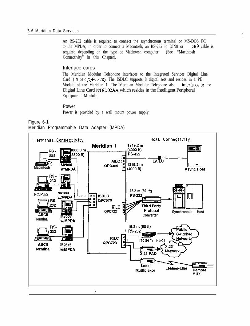
6-6 Meridian Data Services
An RS-232 cable is required to connect the asynchronous terminal or MS-DOS PCto the MPDA; in order to connect a Macintosh, an RS-232 to DIN8 or DB9 cable isrequired depending on the type of Macintosh computer. (See “MacintoshConnectivity” in this Chapter).
,’
Interface cardsThe Meridian Modular Telephone interfaces to the Integrated Services Digital LineCard (ISDLC/QPC578). The ISDLC supports 8 digital sets and resides in a PEModule of the Meridian 1. The Meridian Modular Telephone also interfaces,to theDigital Line Card NT8D02AA which resides in the Intelligent PeripheralEquipment Module.
PowerPower is provided by a wall mount power supply.
Figure 6-1Meridian Programmable Data Adapter (MPDA)
Jerminal ConnectlvWi Host Connectivity
Macintosh
‘C578
RILCQPC723
TerminalWlL”“”
wtMPDA
II 15.2 m (50 ft)
ConverterSynchronous Host
MUX
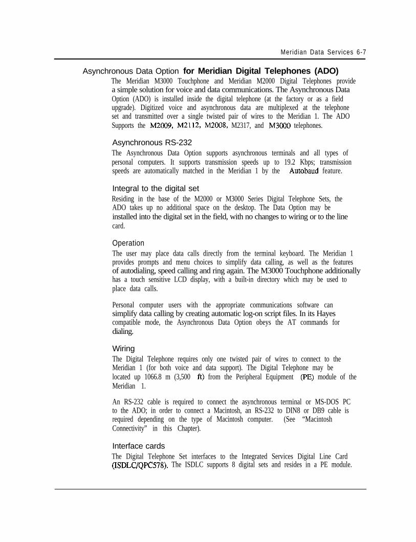
Meridian Data Services 6-7
Asynchronous Data Option for Meridian Digital Telephones (ADO)The Meridian M3000 Touchphone and Meridian M2000 Digital Telephones providea simple solution for voice and data communications. The Asynchronous DataOption (ADO) is installed inside the digital telephone (at the factory or as a fieldupgrade). Digitized voice and asynchronous data are multiplexed at the telephoneset and transmitted over a single twisted pair of wires to the Meridian 1. The ADOSupports the M2009, M2112, M2008, M2317, and M3000 telephones.
Asynchronous RS-232The Asynchronous Data Option supports asynchronous terminals and all types ofpersonal computers. It supports transmission speeds up to 19.2 Kbps; transmissionspeeds are automatically matched in the Meridian 1 by the Autobaud feature.
Integral to the digital setResiding in the base of the M2000 or M3000 Series Digital Telephone Sets, theADO takes up no additional space on the desktop. The Data Option may beinstalled into the digital set in the field, with no changes to wiring or to the linecard.
OperationThe user may place data calls directly from the terminal keyboard. The Meridian 1provides prompts and menu choices to simplify data calling, as well as the featuresof autodialing, speed calling and ring again. The M3000 Touchphone additionallyhas a touch sensitive LCD display, with a built-in directory which may be used toplace data calls.
Personal computer users with the appropriate communications software cansimplify data calling by creating automatic log-on script files. In its Hayescompatible mode, the Asynchronous Data Option obeys the AT commands fordialing.
WiringThe Digital Telephone requires only one twisted pair of wires to connect to theMeridian 1 (for both voice and data support). The Digital Telephone may belocated up 1066.8 m (3,500 ft) from the Peripheral Equipment (PE) module of theMeridian 1.
An RS-232 cable is required to connect the asynchronous terminal or MS-DOS PCto the ADO; in order to connect a Macintosh, an RS-232 to DIN8 or DB9 cable isrequired depending on the type of Macintosh computer. (See “MacintoshConnectivity” in this Chapter).
Interface cardsThe Digital Telephone Set interfaces to the Integrated Services Digital Line Card(ISDLC/QPC578). The ISDLC supports 8 digital sets and resides in a PE module.
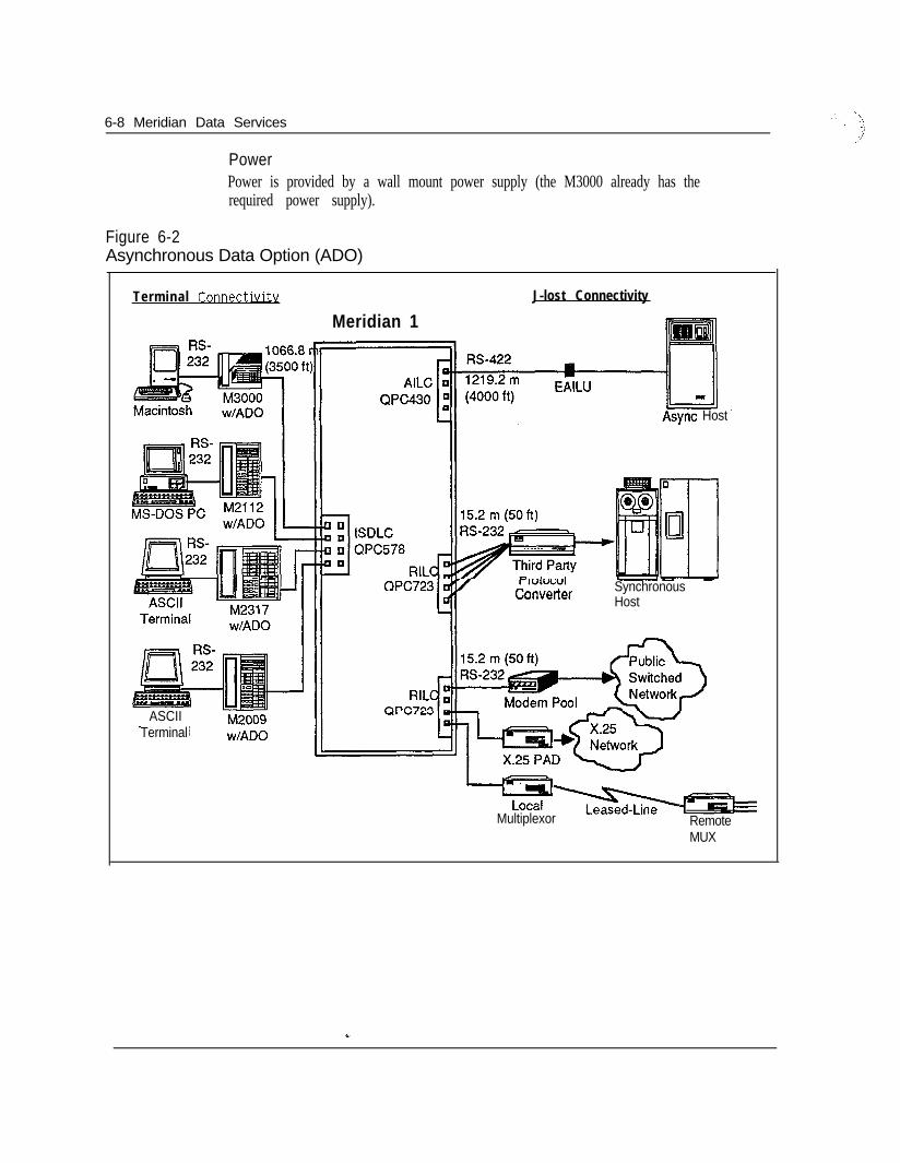
6-8 Meridian Data Services
PowerPower is provided by a wall mount power supply (the M3000 already has therequired power supply).
Figure 6-2Asynchronous Data Option (ADO)
Terminal Connectivitv J-lost Connectivity
Meridian 1
Macintosn
ASCIITerminal
Async Host
wnverter SynchronousHost
Multiplexor RemoteMUX
Meridian Data Services 6-9
Enhanced Asynchronous Interface Line Unit (EAILU)The Enhanced Asynchronous Interface Line Unit (EAILU) is a simple, low-costmeans of connecting ASCII data terminals, teleprinters, word processors, orpersonal computers to the Meridian 1.
The EAILU is available in two versions:- Male version (A0344336)- Female version (A0344337)
A single cable connects your asynchronous ASCII data terminal directly to atelephone jack. The EAILU provides a fully digital connection with no boxes, nobulky cables, and no electrical plugs since the EAILU obtains the necessary powerfrom the terminal unit on pin 4 or 20. Simply plug one end of the EAILU into thestandard RS-232 connector of an asynchronous terminal or MS-DOS PC. Thenplug the other end into your telephone jack.
OperationWith your data terminal connected to the Meridian 1, your data calls now haveconvenience features like speed calling,. auto dialing, even the option of queueing onbusy facilities such as computer ports and modem pools. All are accessed directlyfrom your terminal keyboard by responding to simple menus and prompts.
In addition to data terminals, the EAILU also provides an inexpensive means ofbringing teleprinters, word processors, and personal computers into a Meridian 1network.
Asynchronous host connectivityThe EAILU can also be used to achieve direct connections to host computerslocated up to 1219.2 m (4000 ft) from the switch. (Otherwise the RILC (QPC723)can be used for a direct RS-232 connection to asynchronous ports). When used forasynchronous host computer connections, the EAILU must be the enhanced versionand must interface to E vintage (or higher) of the Asynchronous Interface Line Card(AILC, QPC430).
WiringThe EAILU is a compact EIA RS-232 to RS-422 cable line driver. Since theEAILU communicates with the Meridian 1 through an RS-422 interface, your dataterminal can be located up to 1219.2 m (4,000 ft) away fromthe switch. TheEAILU allows communication at speeds up to 19.2 Kbps.
Direct connectivityThe EAILU connects directly to the DTE RS-232 connector (DB-25) without theneed for an extra data module. The EAILU/AILC are interconnected with two-pairwires (4 wires), and reside in the EPE Module. There is no need to use an RS-232cable for the interconnection.
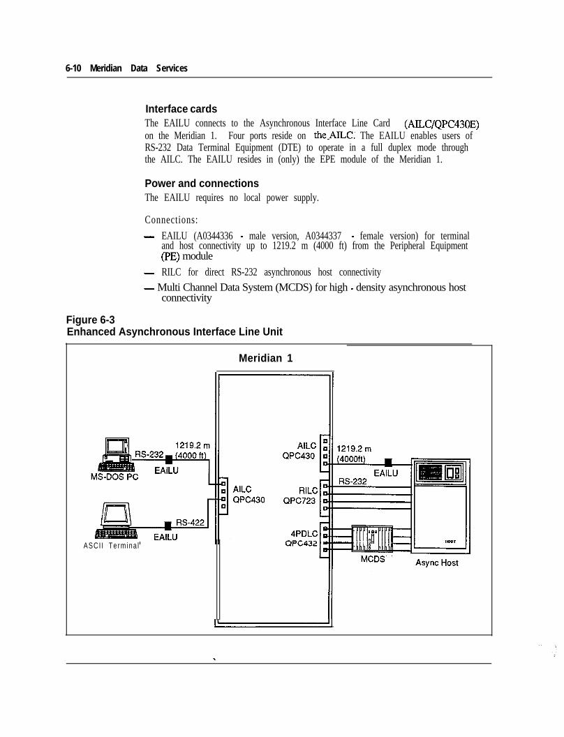
6-10 Meridian Data Services
Interface cardsThe EAILU connects to the Asynchronous Interface Line Card (AILC/QPC430E)on the Meridian 1. Four ports reside on thePILC. The EAILU enables users ofRS-232 Data Terminal Equipment (DTE) to operate in a full duplex mode throughthe AILC. The EAILU resides in (only) the EPE module of the Meridian 1.
Power and connectionsThe EAILU requires no local power supply.
Connections:- EAILU (A0344336 - male version, A0344337 - female version) for terminal
and host connectivity up to 1219.2 m (4000 ft) from the Peripheral Equipment(PE) module
- RILC for direct RS-232 asynchronous host connectivity- Multi Channel Data System (MCDS) for high - density asynchronous host
connectivity
Figure 6-3Enhanced Asynchronous Interface Line Unit
Meridian 1
ASCI I Te rm ina l
Meridian Data Services 6-11
Asynchronous/Synchronous Interface Module (ASIM) - QMTI 1The Asynchronous/Synchronous Interface Module is a stand-alone data module forRS-232 terminals which operate in either the asynchronous and synchronous modes.The ASIM may also be used to interface with a host computer which has RS-232ports.
Asynchronous or synchronousThe ASIM supports asynchronous speeds up to 19.2 Kbps and synchronous speedsup to 56 Kbps.
Asynchronous /synchronous switchThe unit has an easily accessible switch which allows the user to choose eitherasynchronous or synchronous operation.
PhysicalThe ASIM is a desk top unit with a dial keypad and feature keys.
OperationThe Meridian 1 data call processing features such as Auto Dial, Speed Call, RingAgain are supported by keyboard dialing in asynchronous mode and by feature keyson the ASIM in synchronous mode. The ASIM may only interface to DataTerminal Equipment; it may not be used to interface to Data CommunicationsEquipment (e.g. modems).
WiringThe ASIM requires one twisted pair of wires and may be located up to 1219.2 m(4000 ft) from the Peripheral Equipment (PE) cabinet of the Meridian 1. A500/2500 type telephone may also be attached to the ASIM’s voice jack. An RS-232 cable is required to connect the ASIM to the terminal.
Virtual leased line capabilityThe ASIM works with the Digital Trunk Interface (DTI) to provide Virtual leasedline capability. Virtual leased line uses existing T-l facilities to provide theavailability of leased data lines at a lower overall cost. When configured for virtualleased line mode (via two switches on the unit), the ASIM will, on detection of adrop in the connection, hotline continuously to re-establish the connection. Forvirtual leased line capability, use ASIM (QMTl 1) vintage D or greater and DTI(QPC472) vintage C or later. _-
Asynchronous host mode capabilityThe ASIM has been enhanced to provide asynchronous host mode capability. Thisfeature suppresses the sending of prompts and responses to an asynchronous hostcomputer which is accessing the ASIM to place a data call. In effect, asynchronoushost mode permits blind dialing by suppressing the prompts and responses normally

6-l 2 Meridian Data Services
associated with keyboard dialing. This setting can be used when the host computerdialing software is not expecting any response until the far end answers.
This feature is not applicable to dialing by synchronous host computers, since thesecomputers require the use of the hotline feature or keypad dialing to place data calls.For asynchronous host mode capability, use ASIM vintage D or greater.
Interface cardsThe ASIM interfaces to the 4-Port Data Line Card (4PDLC/QPC432) which residesin a PE module.
PowerThe ASIM is equipped with a 11OV AC input power supply. 220V AC and 1OOVAC power supplies are also available .
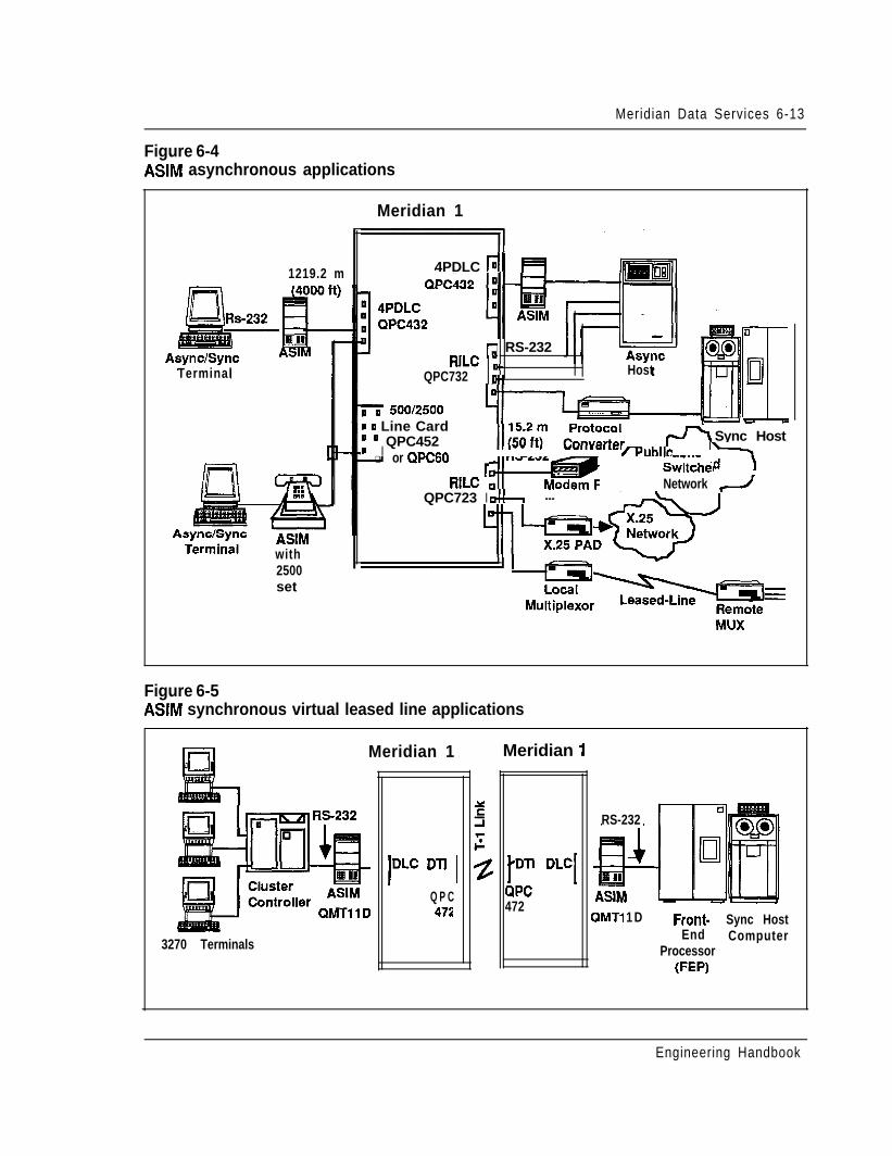
Meridian Data Services 6-13
Figure 6-4ASIM asynchronous applications
Meridian 1
4PDLC tiI1219.2 m
5 RS-232B-h
HostRILC
QPC732
--- Sync Host
Terminal
0 0 500/2500I 0 Line Card
I’ ’ QPC452� q or QPCGO
rPuhlie. --..-iit+P F7
SwitchecNetwork 2RILC
IQPC723 -!I ---
ASIMwith2500set
Figure 6-5ASIM synchronous virtual leased line applications
Meridian 1 Meridian 1
p DLC[
ClPC472
RS-232
ASIMQMTl 1 D
I”‘” Dn IQ P C472 Front- Sync Host
End ComputerProcessor
(FEW
3270 Terminals
Engineering Handbook
6-14 Meridian Data Services
High-Speed Data Module (HSDM) - (QMT21)The High-Speed Data Module (HSDM) is a data module to be used with dataterminal equipment (DTF) in a Northern Telecom High Speed (up to 56 Kbps) orISDN (up to 64 Kbps) environment. The HSDM provides connectivity to theMeridian 1 for local communications, as well as for wide-area~communications overPrimary Rate Interface (PRI) or T-l links to other NT switches. The HSDM iscapable of operating with other data modules using the Data Module to Data Module(DM-DM) protocol as well as with data units for the lOO/DMS-100 using the T-LinkVersion 2 protocol.
High-speed ISDN transmissionThe High-Speed Data Module will support speeds up to 64 Kbps clear channel datatransmission, giving a customer access to ISDN services. Since an ASIM can onlycommunicate at speeds up to 56 Kbps using RS-232C, a customer needing ASIMfunctionality today but wanting V.35 capability or easy migration to an ISDNenvironment in the future would be interested in the High-Speed Data Module.
K-232 /V.35 and virtual leased line capabilityThe High-Speed Data Module supports both RS-232 and V.35 interfaces. Thevirtual leased line capability allows customers to gain the benefits of private lineservice (dedicated access and high availability) while avoiding private line charges.For more information on virtual leased line capability, see HSDM Host Access inthis Chapter.
SL-l/SL-100 settingThe HSDM includes a switch to indicate connection to a Meridian 1 Data Moduleor to a Meridian 1 SL-lOO/DMS-100 Data Unit. This switch is used to insureinterworking in applications involving synchronous, half-duplex data transmissionat speeds less than 56 Kbps.
PhysicalThe High-Speed Data Module is a desk top unit with a dial keypad and feature keys.The appearance of the HSDM to the 1 is similar to the Asynchronous/SynchronousInterface Module.
WiringA single twisted pair wire is needed for data applications. Additionally, an extrajack is provided for connection to a 2500 set.
_-
Interface cardsThe High-Speed Data Module connects to a port on the 4-Port Data Line Card(4PDLC/QPC432) which resides in a Peripheral Equipment module.
Engineering Handbook
Meridian Data Services 6-15
PowerThe HSDM is equipped with a 11OV AC input power supply. 220V AC and 1OOVAC power supplies are also available .
High-Speed Data Card/High Speed Data System - (QPC918)The High Speed Data Card (HSDC) is the circuit board equivalent of two (2) HighSpeed Data Modules conveniently mounted together in a compact rack (the existingMCDS cabinet) with a common power supply which is referred to as a High SpeedData System (HSDS). This will save space and energy compared to individualenclosures.
The High Speed Data System (HSDS) is aimed at providing high densityconnectivity to synchronous hosts but can also be used for asynchronous hostconnections. The HSDS consists of the following components:- MCDS Shelf QSD27- MCDS Power QSY27- 11Ov- MCDS Power QSY32-22Ov- HSDC-2port QPC918- 4portlinecard QPC432- MCDS Desk Cab QCA77 (optional)- MCDS Rack Cab QCA76 (optional)
FeaturesThe High Speed Data Card will provide identical features/functions as the HighSpeed Data Module. The essentials include:- synchronous connectivity up to 64 Kbps- asynchronous connectivity up to 19.2 Kbps- RS232 or V.35 interface- virtual leased line capability, which allows the HSDC to emulate lease-line
operation
Interface cardsThe High Speed Data System connects to a 4 port data line card (QPC432) whichresides in the Peripheral Equipment. _-For technical specifications on the MCDS - Multi Channel Data System, refer tothe “Host Connectivity “ in this Chapter.
Engineering Handbook
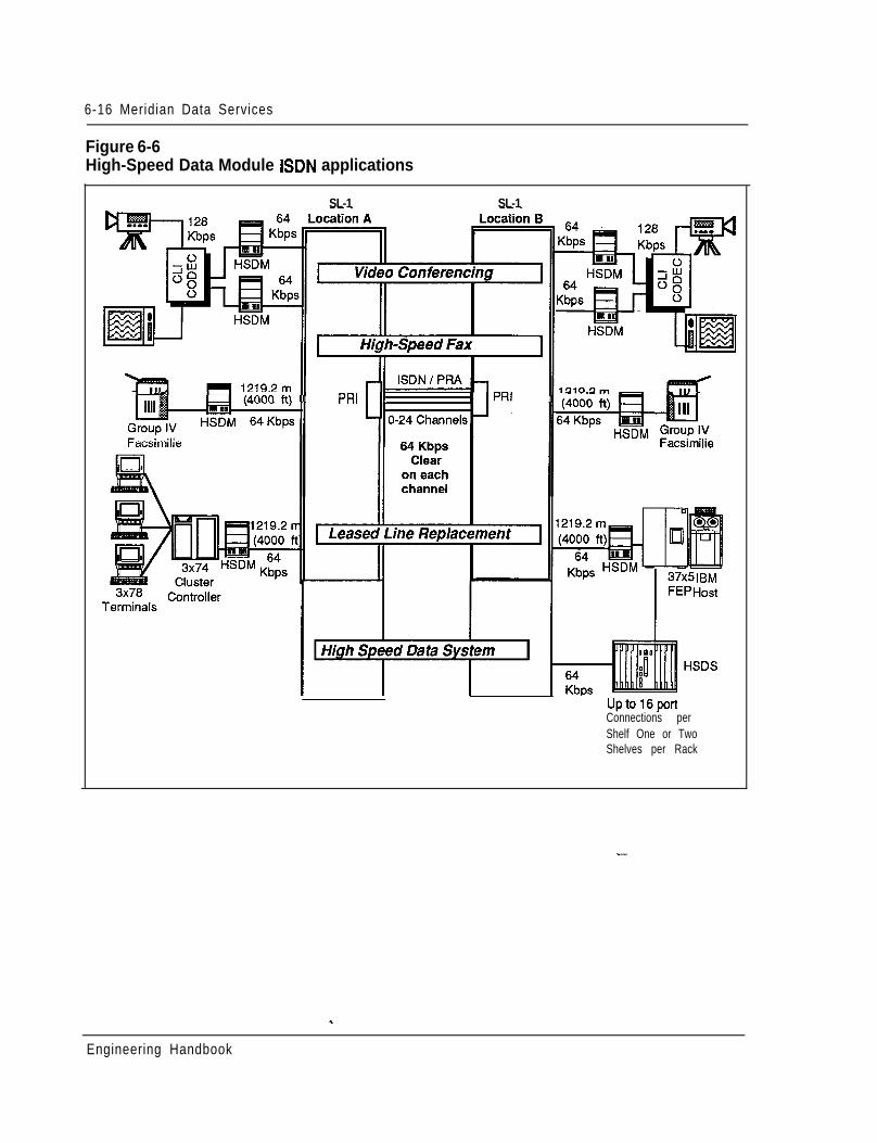
6-16 Meridian Data Services
Figure 6-6High-Speed Data Module ISDN applications
SL-1 SL-1
PRI PRI
Facsimilie
Uptol6portConnections perShelf One or TwoShelves per Rack
Engineering Handbook
Meridian Data Services 6-17
Add-on Data Module (ADM)The QMT12 (V.35 interface) Add-on Data Module (ADM) may be co-located withthe SL- 1 set to provide integrated voice and data communications for synchronousor asynchronous terminals. It can also be used as a stand-alone interface to hostcomputers, printers and modems.
The QMT12 provides the V.35 interface and supports speeds up to 56 Kbps in thesynchronous mode only.
DTE or DCEThe ADM is flexible in that it can interface to data terminal equipment (DTE) suchas computers or terminals, and data communications equipment (DCE) such asmodems and some host computer ports. A switch setting determines the DTE/DCEfunctionality of the ADM. (The ASIM is recommended for DTE-onlyrequirements).
The ADM is recommended as the primary choice where a customer requires asynchronous V.35,56 Kbps, DCE link.
PhysicalThe Add-on Data Module is a desktop unit similar in style to the SL-1 set and otheradd-on units (such as the handsfree unit). The ADM includes a Data SpeedSelector, a Data Option Switch (for choosing other parameters), and severalindicator lamps.
OperationThe ADM can be set to the desired transmission rate by the user. In the ADMasynchronous mode, the terminal keyboard may be used for placing data calls, withthe features of Auto Dialing, Speed Calling, and Ring Again. In the co-located orsynchronous mode, the SL-1 telephone keypad is used to place data calls.
WiringIn the co-located mode, the ADM requires only the existing two pair wiring of theSL-1 set to provide simultaneous voice and data communications. In the stand-alone mode, the ADM requires one pair. A V.35 cable is used to connect to theterminal, printer, host port, or modem (a switch must be set for use with a modem).The ADM may be located up to 1219.2 m (4000 ft) from the PE Module of theMeridian 1. _-
PowerThe ADM has an internal power supply, which monitors the local AC power inputderived through the 24 volt transformer (PO593922 or PO610756 - orderedseparately) from commercial 110 volts AC.
Engineering Handbook
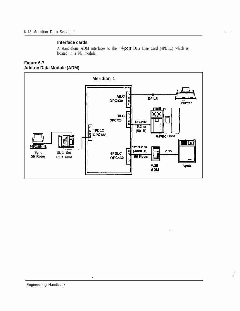
6-18 Meridian Data Services
Interface cardsA stand-alone ADM interfaces to the 4-port Data Line Card (4PDLC) which islocated in a PE module.
Figure 6-7Add-on Data Module (ADM)
Sync-^ .I.SO KDPSSL-1 SetPlus ADM
Meridian 1
RILCQPC723
II Async Host
--
Engineering Handbook
Meridian Data Services 6-19
EasyLAN with Meridian Extension - (A0345240)EasyLAN with Meridian Extension is a low-cost local area network product forMS-DOS PCs in the office. EasyLAN with Meridian Extension allows users toshare expensive peripherals such as laser printers, plotters, high-capacity hard disksand tape backup units by using twisted pair wiring and the Meridian 1. EasyLANwith Meridian Extension is a cost-effective solution for companies of any sizewishing to share printers distributed among work groups or wishing to support filesharing within a work group.
Set-upAny MS-DOS PC connected to the Meridian 1 can access the benefits of EasyLANwith Meridian Extension.
Once the data connection is in place and EasyLAN with Meridian Extensionsoftware is installed, the end-user needs only to configure the software with the dataextension numbers of the other PC users in the group and the port number of theremote PC’s physically attached printer.
Key benefitsA pop-up dialing menu works with most third-party application software packagesto make remote file access and printing transparent to the user.
Mnemonic dialing from the user’s directory simplifies access to computer resources.
Users can assign names to computer resources (e.g., “bill”) so that they can moreeasily remember those resources. Users can then simply place a call to the namedresource (“bill” for the PC with a laser printer attached) without knowing the dataextension of that resource.
EasyLAN with Meridian Extension requires only 20 Kbytes of Random AccessMemory (RAM) per configured communications port. Since the program runs inbackground mode, EasyLAN with Meridian Extension can be running while the PCuser is working with another application (e.g., spreadsheet).
One or more print/disk servers can be configured and shared. These servers neednot be dedicated; that is, they can be used for normal PC applications while actingas print/disk servers.
Key points _-
Each PC in the network needs its own numbered copy of EasyLAN with MeridianExtension software. The software is not copy-protected, so backup disks can bemade, but a code-checking routine in the software prevents duplicate use of thesame software diskettes on a network.
An EasyLAN with Meridian Extension network can practically include up to 32users, as that many names and associated data extensions can be configured.Theoretically, an EasyLAN with Meridian Extension network is limited only by the
w
Engineering Handbook
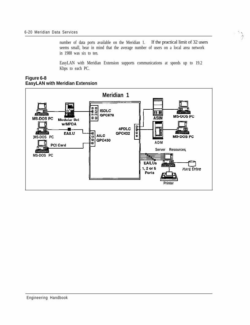
6-20 Meridian Data Services
number of data ports available on the Meridian 1. If the practical limit of 32 usersseems small, bear in mind that the average number of users on a local area networkin 1988 was six to ten.
EasyLAN with Meridian Extension supports communications at speeds up to 19.2Kbps to each PC.
Figure 6-8EasyLAN with Meridian Extension
MS-DOS PC
Meridian 1
II I ASIM
MS-DOS PC
ADM
Server Resources
Printer
Hard Drive
Engineering Handbook
6-22 Meridian Data Services
The ASIM may be conveniently switched between asynchronous and synchronousoperation. The ASIM also supports Hotline and Auto-answer features using thetelephone keypad.
The Asynchronous/Synchronous Interface Module may only interface to a DataTerminal Equipment (DTE) port. If connection to Data Communication Equipment(DCE) (e.g. synchronous modem) is required, the stand-alone ADM should be used.For more information, see also “Data Services Terminal Connectivity” in thisChapter.
Using an ASIM as well as the Digital Trunk Interface (DTI), customers can now setup virtual leased lines between Meridian 1 locations. This arrangement allowscustomers to gain the benefits of private line service (dedicated access and highavailability) while avoiding private line charges.
High-Speed Data Module (HSDM) - QMT21The High-Speed Data Module (HSDM) is used for both RS-232 and V.35 interface.It provides all of the functionality of the ASIM but adds the ability to run at speedsof 64 Kbps and to interface to V.35 ports. For more information, see also “DataServices Terminal Connectivity” in this Chapter.
The High-Speed Data Module operates in a Northern Telecom ISDN environmentat speeds up to 64 Kbps. Combined with the Primary Rate Interface (PRI), theHSDM provides access to wide-area communications over T- 1 links to otherNorthern Telecom switches. The HSDM is compatible with Datapath units usedwithin 100 and DMS-100, DMS-250, DPNJO, and DPN-100 environments.
Along with the ASIM, the HSDM also provides virtual leased line capability. Withthe Digital Trunk Interface (DTI) or Primary Rate Interface (PRI), the High-SpeedData Module automatically recovers when the line goes down by hotlining until theconnection is re-established. Virtual leased line capability provides dedicatedaccess and high data availability at line charges lower than private lines.
Enhanced Asynchronous Interface Line Unit (EAILU)The Enhanced Asynchronous Interface Line Unit (EAILU) is a simple, low-costmeans of connecting ASCII data terminals or PCs to the Meridian 1. The EAILU isavailable in two versions:- Male version (A0344336)- Female version (A0344337)
- -
A single cable connects your asynchronous terminal directly to a modular phonejack. There are no boxes, bulky cables and no electrical plugs since the EAILUobtains its power from the terminal unit’s EIA pin 4 or 20. The EAILU allowsspeeds up to 19.2 Kbps.
Engineering Handbook
‘X.
Meridian Data Services 6-23
The EAILU can also be used to provide direct asynchronous host connectivity up to1219.2 m (4000 I?) from the Meridian 1 Peripheral Equipment (PE) Module,without the use of data modules.
The EAILU connects to the Asynchronous Interface Line Card on the Meridian 1.The AILC accommodates up to 4 ports. For more information, see also “DataServices Terminal Connectivity” in this Chapter.
High-Speed Data Card (HSDC) (QPC918) or High-Speed Data SystemThe High Speed Data Card (HSDC) provides RS232 / V.35 Interface for high portdensity. It is the circuit board equivalent of two (2) High Speed Data Modulesconveniently mounted together in a compact rack (the existing MCDS cabinet) witha common power supply which is referred to as a High Speed Data System (HSDS).This saves space and energy compared to individual enclosures.
The High Speed Data System (HSDS) is aimed at providing high densityconnectivity to synchronous hosts but can also be used for asynchronous hostconnections.
The HSDS consists of the following components:- MCDS Shelf QSD27- MCDS Power QSY27-11Ov- MCDS Power QSY32-220~- HSDC2por-t QPC918- 4 Port line card QPC432- MCDS Desk Cab QCA77-optional- MCDS Rack Cab QCA76-optional
FeaturesThe High Speed Data Card provides identical features/functions as the High SpeedData Module. The essentials include:- synchronous connectivity up to 64- asynchronous connectivity up to 19.2 Kbps- RS232 or V.35 interface- virtual leased line capability which allows the HSDC to emulate lease-line
operation_-
Engineering Handbook
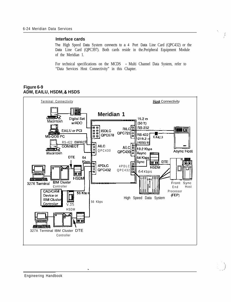
6-24 Meridian Data Services
Interface cardsThe High Speed Data System connects to a 4 Port Data Line Card (QPC432) or theData Line Card (QPC397). Both cards reside in the.Peripheral Equipment Moduleof the Meridian 1.
For technical specifications on the MCDS - Multi Channel Data System, refer to“Data Services Host Connectivity” in this Chapter.
Figure 6-9ADM, EAILU, HSDM, & HSDS
Termina l Connec t i v i t y Host Connectivity
L Meridian 1
t==? RS-422 DIRECAILCQ P C 4 3 0
Cont ro l le r
P
56 Kbps
H S D M
Ie
AILC ~114QPC430
4 P D L CQ P C 4 3 2
Front SyncE n d H o s t
Processor
High Speed Data System (FW
327X Terminal IBM Cluster DTECont ro l le r
\!,. ; I
_’
Engineering Handbook
Meridian Data Services 6-25
Multi-Channel Data System (MCDS)The MCDS provides high density asynchronous host connections. It is anasynchronous rack mounted Add-on Data Module system that allows the efficientconnection of multiple computer ports.- The MCDS consists of multiple Add-onData Module equivalent circuit cards which are mounted together in a compact rackwith a common power supply. This arrangement provides space savings, and alower power requirement than with individual ADMs.
Asynchronous, Answer-OnlyThe MCDS provides an asynchronous answer-only interface between multiportcomputers and the Data Line Cards. The host port cannot originate a dataconnection using the MCDS .
Physical ConfigurationThe MCDS consists of:- Desk mount cabinet (QCA77)- Rack mount cabinet (QCA76)- Shelf (QSD27)- MCDS Asynchronous Card (QPC397)- Power supply (QSY27)
Acting as an Add-on Data Module, each MCDS Asynchronous Card (MCDS-AC)is capable of connecting to 4 computer ports. Each MCDS shelf can accommodateup to 8 MCDS Asynchronous Cards, for a total of 32 ports.
Each shelf requires one power supply. An MCDS in a rack-mount cabinet consistsof a maximum of two shelves offering a total of 64 ports. The rack has additionalroom for optional diagnostic equipment.
An MCDS in a desktop cabinet comprises one shelf with associated power supply; atotal of 32 ports can be configured.
OperationThe MCDS is designed to operate without operator intervention. Each of its portscan operate independently of the other ports. Each of the sixty-four (64) ports caninterface to different host computers operating at different speeds and with differentdata formats. If desired, all the ports can serve a single.host computer.
WiringEach port of the MCDS is connected using one twisted pair, and the MCDSequipment can be located up to 12 19.2 m (4000 ft) from the PE Module of theMeridian 1. Industry standard 25-pair telephone cables with Amphenol connectorsare used to connect the MCDS to the Main Distribution Frame. RS-232 cables areused to connect the host ports to the MCDS.
Engineering Handbook
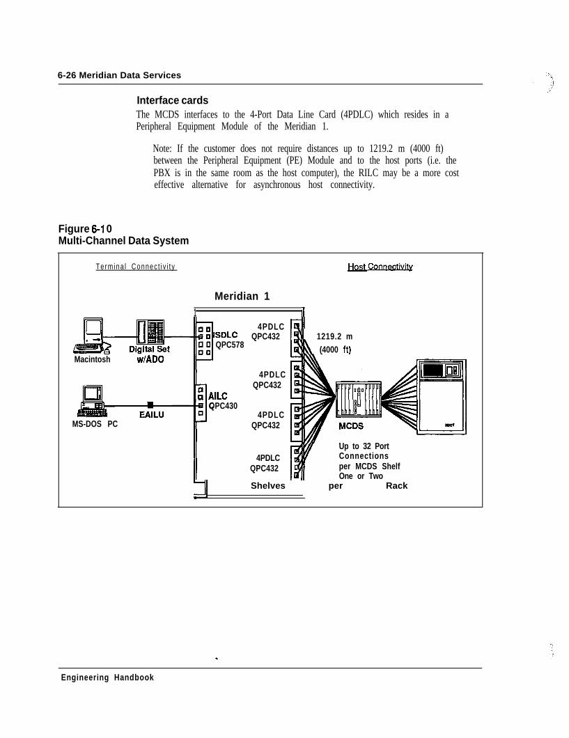
6-26 Meridian Data Services
Interface cardsThe MCDS interfaces to the 4-Port Data Line Card (4PDLC) which resides in aPeripheral Equipment Module of the Meridian 1.
Note: If the customer does not require distances up to 1219.2 m (4000 ft)between the Peripheral Equipment (PE) Module and to the host ports (i.e. thePBX is in the same room as the host computer), the RILC may be a more costeffective alternative for asynchronous host connectivity.
Figure 6-l 0Multi-Channel Data System
Termina l Connec t i v i t y
Macintosh w/ADO
MS-DOS PC
Meridian 11 I100
q ISDLCi ; QPC578
F:: AILC
QPC4300
4PDLCQPC432
4PDLCQPC432
4PDLCQPC432
4PDLCQPC432
!I 1219.2 m\ (4000 ft)
. .Conneu
Up to 32 PortConnectionsper MCDS Shelf
ldll One or Two171 Shelves per Rack
Engineering Handbook
Meridian Data Services 6-27
Integrated Services Digital Network-Applications Protocol - (ISDN/AP)In today’s competitive business environment, success is dependent upon theintelligent application of voice and data communication services to meet strategicbusiness objectives.
ISDN Applications Protocol (ISDN/AP) provides integrated host computer andPBX functionality. It is designed to give networks the capability to providecomprehensive solutions to complex business communications problems.
ISDN Applications Protocol is a powerful link that brings together the callprocessing capability of the versatile Meridian 1 with the host computer ability toprocess vast amounts of information. Together, they combine to create highlyefficient corporate communications networks.
The intelligent linkISDN/AP allows the Meridian 1 to receive messages from a host computerrequesting various call processing functions and allows the Meridian 1 to returnstatus messages to the computer that provide real-time information about theprogress and status of requested actions. Consequently, ISDN/AP now allowsusers, via their application program, to tie previously separate PBX and computerfunctions into a single, integrated process.
FunctionISDN/AP is an RS-232 or RS-422 synchronous link, presently based on a NorthernTelecom proprietary protocol. It operates at speeds up to 64 Kbps. The functionsprovided by ISDN/AP include the following:- Call processing- Call status- Incoming call notification,- Directory number update- Integrated messaging- System maintenance and administration.
ISDN-AP initial applicationsThe following are initial applications being developed by Digital EquipmentCorporation: - -- Telephone Support Center - allows an incoming or outgoing call to be
associated with a database resident on the VAX such as a customer history fileor a telemarketing script. This service allows voice and data calls to besimultaneously and repeatedly transferred. Applications include telemarketing,operations and services, repair and dispatch centers.
- Directory Look-up and Automated Directory Dialing - allows a user to scrollthrough a corporate or personal directory in a VAX database and place a call toanyone via a single keyboard entry.
Engineering Handbook
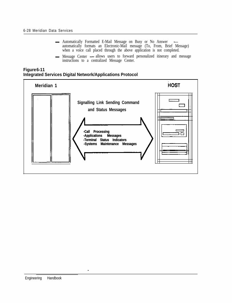
6-28 Meridian Data Services
- Automatically Formatted E-Mail Message on Busy or No Answer -automatically formats an Electronic-Mail message (To, From, Brief Message)when a voice call placed through the above application is not completed.
- Message Center - allows users to forward personalized itinerary and messageinstructions to a centralized Message Center.
Figure 6-11Integrated Services Digital Network/Applications Protocol
Meridian 1
Signalling Link Sending Command
I and Status Messages
-Call Processing-Call Processing-Applications Messages-Applications Messages-Terminal Status Indicators-Terminal Status Indicators-Systems Maintenance Messages-Systems Maintenance Messages
HOST
Engineering Handbook
Meridian Data Services 6-29
IBM connectivityNorthern Telecom continues to lead the way in providing switched and dedicatedconnectivity in IBM environments. Products available for connecting to IBMdevices include the following:- PC Interface Card (PCI) - for MS-DOS Personal Computer direct connection to
the Meridian 1- Coax Elimination and Switching System (CESS) - for VT-100 emulation, 3270
host access, and reduction of coaxial cable needs for 3270 terminals- EasyLAN with Meridian Extension - for cost effective printer and resource
sharing among IBM PCs and clones- Baluns - for coax, twinax, and dual coax wiring reduction- High-Speed Data Module - for networking of cluster controllers and front end
processors (See “Data Services Terminal Connectivity” and “Data Services HostConnectivity” in this Chapter)
- RS-232 Interface Line Card (RILC) direct connection to third-party protocolconverters for PC or asynchronous terminal access to IBM computers. (See“Data Line Cards” in this Chapter)
Meridian Data Services provides flexible and cost-effective solutions to enhanceIBM PC, 3270 terminal, and IBM host data communications.
IBM personal computers may be connected to the Meridian 1 by three mainmethods:- the Asynchronous Data Option (ADO) in a Northern Telecom M2000 or M3000
digital telephone- the Enhanced Asynchronous Interface Line Unit (EAILU) if an RS-232 port is
provided- the PC Interface Card (PCI) that plugs into an expansion slot on the PC
motherboard
One may also use an ASIM which, like the EAILU, connects to the PC via the RS-232 serial port. The ADO, EAILU, and ASIM are discussed in “Data Services
After the IBM PC is connected to the Meridian 1, the user can take advantage of thenumerous circuit switched applications that the Meridian Data Network provides.For low-cost local area networking, Northern Telecom provides EasyLAN withMeridian Extension that gives MS-DOS PCs connected to the Meridian 1 the abilityto share files and printers - the two most prevalent uses of LANs.
_-
Engineering Handbook
6-30 Meridian Data Services
In addition to being able to connect IBM PCs to the Meridian 1, a number of waysexist to connect different IBM terminals (see also “Data Services TerminalConnectivity” in this Chapter). This section focuses on coaxial cable reduction andreplacement via twisted pair wiring. Twisted pair wiring is cost-effective and allowsfor easier moves and changes compared with coaxial cable.
Host computers can be connected to the Meridian 1 in a number of ways includingthe new High-Speed Data Module that provides 64 Kbps clear channel synchronoustransmission (see “Data Services Host Connectivity” section).
Personal Computer Interface Card (PCI) - QPC512 _The Personal Computer Interface Card (PCI) is a PC expansion card which installsdirectly inside an MS-DOS compatible personal computer, using any availableexpansion slot. The PC1 card is used to provide an RS-422 connection to theMeridian 1.
If the PC has no slots available but is equipped with an RS-232 serial port, theEAILU can be used; alternately, the ASIM or ADO may also be used (see also “DataServices Terminal Connectivity” in this Chapter).
SpeedsThe PC1 Card supports asynchronous speeds up to 19.2 Kbps. The PC1 card may beused to access asynchronous host computers, printers and other personal computers.
The personal computer user may access an IBM host by making a data call through aMeridian l-compatible 3270 Protocol Converter or 3270 Emulator. NorthernTelecom has found the Perle and Local Data protocol converters to be compatiblewith the RILC and AILC. The RILC can also be connected to several other IBMprotocol converters. (See “Third Party Compatibility Testing Program” in thisChapter).
Communications softwareThe PC1 requires a communications software package (such as Crosstalk XVI orSmartcom III). Such software allows the personal computer to emulate an ASCIIterminal, so that the user can dial from the keyboard to make data calls. Thissoftware may also be used to transfer files between personal computers, or between apersonal computer and a host computer.
File transferFile transfer from PC to PC and from PC to Macintosh can be performed with eitherASCII file transfer (using X-on/X-off flow control) or binary’transfer (using theXModem protocol). Transmission speeds up to 19.2 Kbps are supported by the PC1card (although the PC itself may be limited to 9600 bps).
OperationData calls are placed directly from the personal computer keyboard, allowing accessto such features as Auto Dialing, Speed Calling, Ring Again, and Modem PoolCalling. U . .
Engineering Handbook
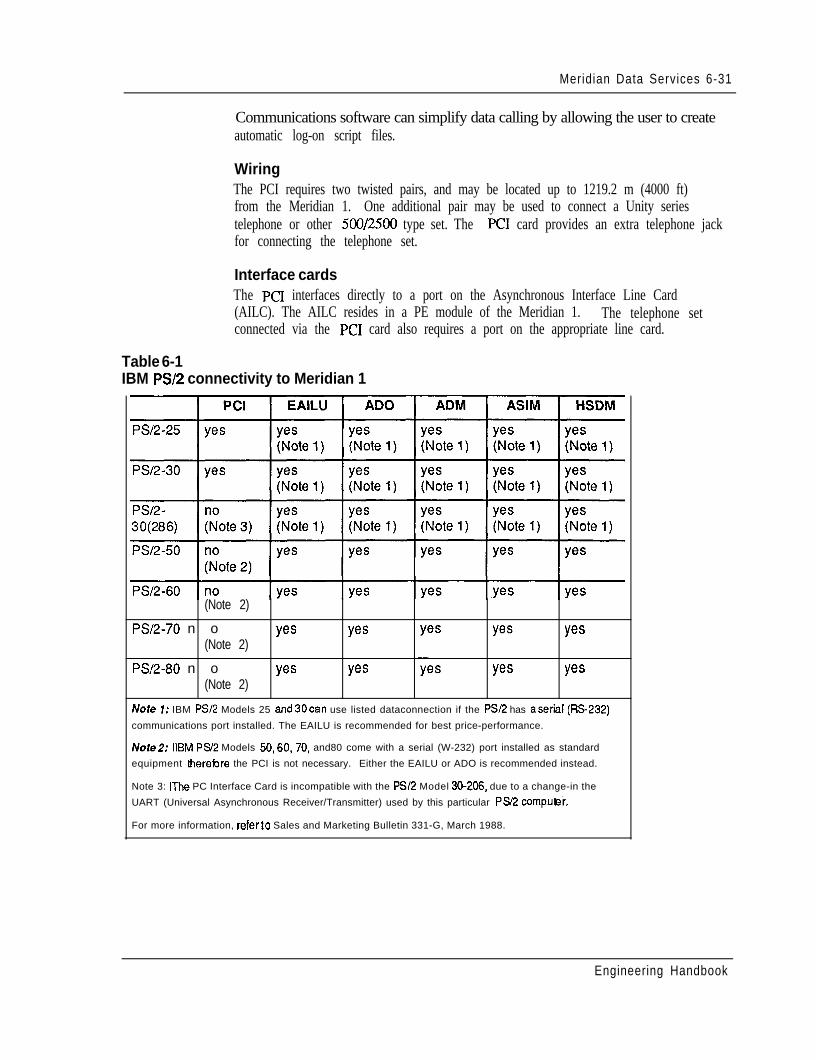
Meridian Data Services 6-31
Communications software can simplify data calling by allowing the user to createautomatic log-on script files.
WiringThe PCI requires two twisted pairs, and may be located up to 1219.2 m (4000 ft)from the Meridian 1. One additional pair may be used to connect a Unity seriestelephone or other 500/2500 type set. The PC1 card provides an extra telephone jackfor connecting the telephone set.
Interface cardsThe PC1 interfaces directly to a port on the Asynchronous Interface Line Card(AILC). The AILC resides in a PE module of the Meridian 1. The telephone setconnected via the PC1 card also requires a port on the appropriate line card.
Table 6-1IBM PS/2 connectivity to Meridian 1
(Note 2)
PS/2-70 n o yes yes(Note 2)
PS/2-80 n o yes yes(Note 2)
yes
yes
yes
yes
Nofe 7: IBM PS/2 Models 25 and30can use listed dataconnection if the PSI2 has aserial (RS232)
communications port installed. The EAILU is recommended for best price-performance.
Notel: HBM PS/2 Models 50,60,70, and80 come with a serial (W-232) port installed as standard
equipment therebre the PCI is not necessary. Either the EAILU or ADO is recommended instead.
Note 3: IThe PC Interface Card is incompatible with the PS/2 Model 30-206. due to a change-in the
UART (Universal Asynchronous Receiver/Transmitter) used by this particular Ps/2 compuei .
For more information, referto Sales and Marketing Bulletin 331-G, March 1988.
Engineering Handbook
6-32 Meridian Data Services
Coax Elimination and SwitFhing System (CESS) _The Coax Elimination and Switching System access IBM and ASYNC hosts from asingle 3270 terminal. It substantially eliminates the need for coaxial cable betweenIBM 3270 display terminals and IBM cluster controllers, replacing the coax withstandard twisted pair wiring. IBM terminal users can have switched access toasynchronous and IBM hosts and to multiple controllers. The, controller ports can beshared by many additional users through port contention.
VT1 00 terminal emulationBy using the Coax Elimination and Switching System (CESS), one gains access tothe ASCII world from a 3270 terminal. Screen menus assist in the selection ofASCII or IBM mode and any desired call set up parameters. In ASCII mode, theIBM 3270 emulates a DEC VT 100 or VT52 terminal.
Reduction of coaxial cablingThe Coax Elimination and Switching System enhances the value of an IBM 3270display terminal and minimizes installation and relocation expenses.
By using Coax Interface Modules (CIMs), coaxial cabling can be replaced withstandard twisted pair wiring. Standard twisted pair wiring provides flexibility andgrowth for your data network - moves and changes are easier and less expensive toadminister.
Meridian 1 advantagesThe Meridian 1 switching capability enhances any data network. Port contentioneliminates the requirement to have a dedicated controller port per terminal.
In situations where terminals do not need dedicated access, multiple terminals mayuse the concentration functions of the Meridian 1 to share a smaller number ofcontroller ports. The reduction in the number of ports required results in costsavings.
Multiple controllers with different protocolsThe Multi-Channel Coax System (MCCS) can be connected to multiple clustercontrollers using the same or different protocols (e.g., SNA/SDLC, BSC).
OperationThe Coax Interface Module provides the Hotline feature, as well as keyboard dialingand Auto Dial directly from the terminal keyboard. - -
System configurationThe Coax Elimination and Switching System consists of individual Coax InterfaceModules (CIMs) for connection of terminals to the Meridian 1, and a Multi ChannelCoax System (MCCS) for connection of cluster controllers to the Meridian 1. TheMCCS consists of up to sixteen (16) Coax Interface Cards (CIC). Each CIC has two(2) ports, which means that the MCCS can accommodate a maximum of 32 ports.
Engineering Handbook
Meridian Data Services 6-33
Wiring (switched connection)The IBM 3270 terminal is connected to the CIM via coaxial cable. The CIM isconnected to the Meridian 1 via one twisted pair of wires.
Additional wire pairs may be used to support an SL-1 set or a standard 500/2500telephone.
The MCCS is connected to the cluster controller via coaxial cable. On the Meridian1 side, the MCCS connects to the 4PDLC card via twisted pair telephone wiring.
Non-switched connectionThe CIM can be directly connected to a cluster controller port to provide a non-switched connection between an IBM 3270 terminal and associated clustercontroller. This configuration can be employed where there is a need to eliminate asubstantial amount of coaxial cable used by terminals with no requirement forswitched access to other computers.
Inactivity timerThe CIM includes an inactivity timer which will drop a terminal user’s connectionthrough the SL-1 after a user-defined period of inactivity. This timer can be used toprovide improved access to computer ports by disabling connections which are notbeing actively used.
112.6 km (70 miles) via RPEUsing Remote Peripheral Equipment (RPE), the IBM cluster controller may belocated up to 12.6 km (70 miles) from its terminals. Refer to “Data Services Wide-Area Networking” section for more information on RPE.
Interface cardsThe CIM and CIC connect to the 4-Port Data Line Card or to spare data ports on theData Line Card. These cards reside on a Peripheral Equipment shelf of the Meridian1. Note that the AC vintage or later of the Coax Interface Card is required forconnection to Model 3174 cluster controllers.
Terminals supportedCESS supports the following IBM terminals and personal computers:- 3191 (in 3278 emulation mode)- 3178 - -- 3278 (Models 2 through 5)- 3279 (Without Program Symbols and Color Convergence),- 3 179 (in 3279 emulation mode)- 3 180 (in 3278 emulation mode)- 3270-PC (in CUT mode, without file transfer or program symbols)- IBM PC with IBM 3278/79 coax cards or with IRMA boards (operating in 3278
emulation mode, without file transfer or program symbols)
Engineering Handbook
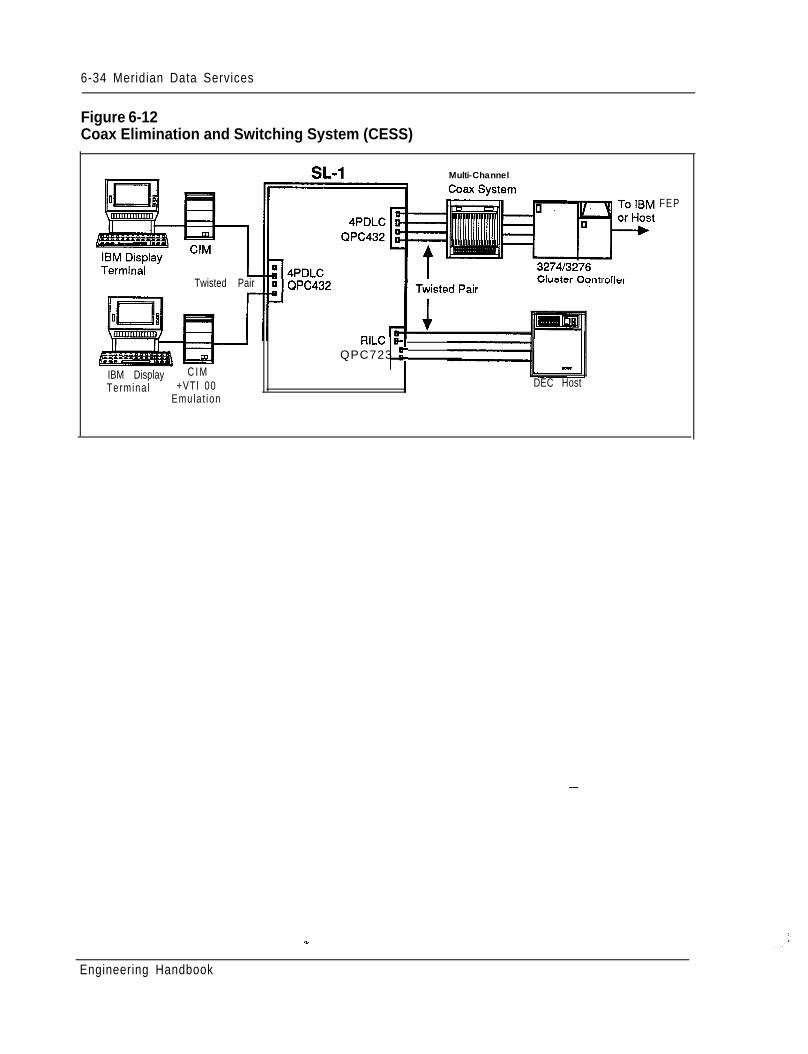
6-34 Meridian Data Services
Figure 6-12Coax Elimination and Switching System (CESS)
Twisted Pair
IBM Display C I MTermina l +VTl 00
Emula t ion
Multi-Channel
RILC B-QPC723 r
DEC Host
FEP
Engineering Handbook
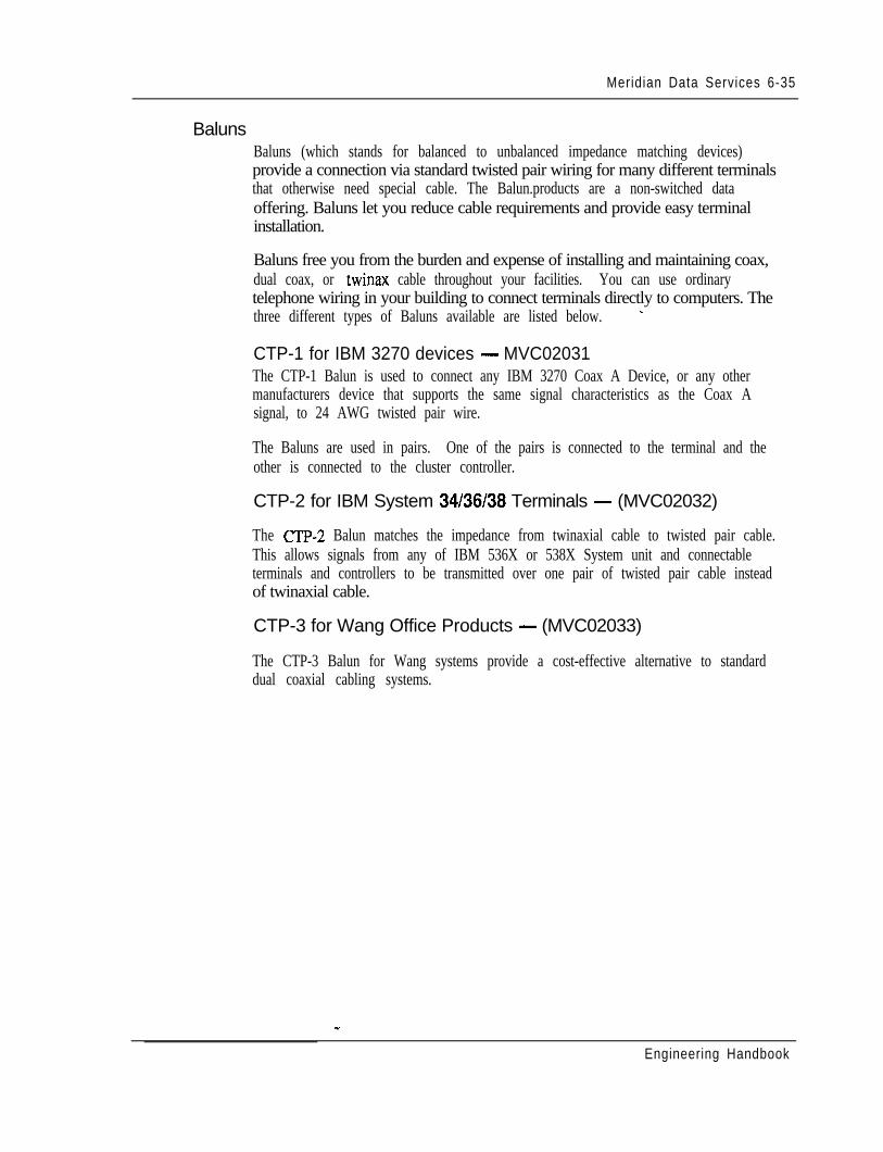
Meridian Data Services 6-35
BalunsBaluns (which stands for balanced to unbalanced impedance matching devices)provide a connection via standard twisted pair wiring for many different terminalsthat otherwise need special cable. The Balun.products are a non-switched dataoffering. Baluns let you reduce cable requirements and provide easy terminalinstallation.
Baluns free you from the burden and expense of installing and maintaining coax,dual coax, or twinax cable throughout your facilities. You can use ordinarytelephone wiring in your building to connect terminals directly to computers. Thethree different types of Baluns available are listed below. _
CTP-1 for IBM 3270 devices - MVC02031The CTP-1 Balun is used to connect any IBM 3270 Coax A Device, or any othermanufacturers device that supports the same signal characteristics as the Coax Asignal, to 24 AWG twisted pair wire.
The Baluns are used in pairs. One of the pairs is connected to the terminal and theother is connected to the cluster controller.
CTP-2 for IBM System 34/36/38 Terminals - (MVC02032)
The CTP-2 Balun matches the impedance from twinaxial cable to twisted pair cable.This allows signals from any of IBM 536X or 538X System unit and connectableterminals and controllers to be transmitted over one pair of twisted pair cable insteadof twinaxial cable.
CTP-3 for Wang Office Products - (MVC02033)
The CTP-3 Balun for Wang systems provide a cost-effective alternative to standarddual coaxial cabling systems.
Engineering Handbook
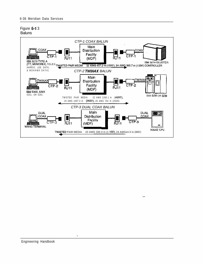
6-36 Meridian Data Services
Figure 6-l 3Baluns
CTP-1 COAX BALUN
(ITT, MEMOREX, TELEXH A R R I S , L E E D A T A ,& M O H A W K D A T A ) CTP-2 TWINAX BALUN
5 2 5 1 , O R 5 2 9 1T W I S T E D P A I R M E D I A 2 2 A W G 1 2 8 0 . 1 m (4iOO’),
IBM St36 OR S/38
2 4 A W G 1 0 9 7 . 3 m (3600’), 2 6 A W G 7 6 2 m ( 2 5 0 0 3
-CTP-3 DUAL COAX BALUN
I CTP-3 RJq1LWti
TWISJED PAIR MEDIA 22 AWG 335.3 m (1 lOO’), 24 AWGz4.3 m (900’)YYHPJ” Ll-”
_-
Engineering Handbook
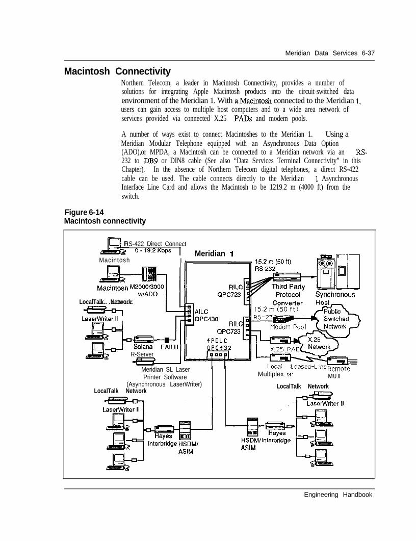
Meridian Data Services 6-37
Macintosh ConnectivityNorthern Telecom, a leader in Macintosh Connectivity, provides a number ofsolutions for integrating Apple Macintosh products into the circuit-switched dataenvironment of the Meridian 1. With aMacintosh connected to the Meridian 1,users can gain access to multiple host computers and to a wide area network ofservices provided via connected X.25 PADS and modem pools.
A number of ways exist to connect Macintoshes to the Meridian 1. Using aMeridian Modular Telephone equipped with an Asynchronous Data Option(ADO),or MPDA, a Macintosh can be connected to a Meridian network via an RS-232 to DB9 or DIN8 cable (See also “Data Services Terminal Connectivity” in thisChapter). In the absence of Northern Telecom digital telephones, a direct RS-422cable can be used. The cable connects directly to the Meridian 1 AsynchronousInterface Line Card and allows the Macintosh to be 1219.2 m (4000 ft) from theswitch.
Figure 6-14Macintosh connectivity
S-422 Direct Connect0-19.2Kbps 1
Macintosh I IMeridian
Iir0IEl
SvnchronousLocalTalk Network
Laseater III
SolanaR-Server
Multiplex :or M U XMeridian SL LaserPrinter Software
(Asynchronous LaserWriter)LocalTalk Network
LocalTalk Network
HSDMIlnterbridgeASIM
Engineering Handbook
6-38 Meridian Data Services
Direct RS-422 connectionDirect Macintosh connectivity:- DB9-to-RJll - (A0326760)- DB9-to-DB25 - (A0326761)- DIN%to-RJl 1 - (A0326762)- DIN8-to-DB25 - (A0326763)
The Macintosh (and asynchronous terminals which provide the RS-422 interface)can be connected directly to the Meridian 1 without the need for a data module.
Both the Macintosh and LaserWriter printer may be connected directly to a port onthe Asynchronous Interface Line Card providing a simple and inexpensiveconnection to the Meridian 1
Asynchronous transmission up to 19.2 Kbps is supported. The Macintosh may beused to access asynchronous hosts, IBM hosts (through third-party protocolconverters), packet switching networks (through an X.25 PAD), modem pools andother personal computers.
Communication softwareASCII terminal emulation software such as MacTerminal must be used. Thesoftware used should provide the “long break” function (1.6 seconds) fordisconnecting data calls.
File transferFile transfer from Mac to Mac and from Macintosh to PC can be performed atspeeds up to 19.2 Kbps, with either ASCII transfer (using X-on/X-off flow control)or binary transfer (using a protocol common to both computers, such as Xmodem).
OperationThe Macintosh user can take advantage of Meridian 1 data call processing featuressuch as Auto Dial, Speed Calling and Ring Again. Data calls are placed using theMac keyboard.
WiringDirect RS-422 connections require two twisted pair of wires, allowing theMacintosh computer to be located up to 1219.2 m (4000 ft)from the Meridian 1 .The Macintosh Plus, SE and II have a DIN8 connector. Macintoshes older than theMacintosh Plus (including the Macintosh 512K) use a DB9 connector.
Simple cable connectionMeridian Data Services offers cables with DIN8 and DB9 connectors and whichterminate in RJl 1 connectors (for direct RS-422 connection) and DB25 connectors
Engineering Handbook
Meridian Data Services 6-39
(for connection to ADO or EAILU). Simply plug the appropriate cable into theMacintosh modem port, and plug the other end of the cable to an ADO or a walljack to complete the data connection to the Meridian 1 .
Interface cardThe Macintosh interfaces directly to the Asynchronous Interface Line Card (AILC).This card resides on a Peripheral Equipment module of the Meridian 1.
,
Engineering Handbook
6-40 Meridian Data Services
Meridian SL laser printer software package - (NPS5039646Ll)Macintoshes not connected to an AppleTalk network now have the ability to share alaser printer by using the Meridian SL laser printer software package. This softwarepackage provides laser printer sharing without-the need for a LAN. Using standardphone wire and the Meridian 1, the installation is simple and,cost-effective.
Features and benefitsThe Meridian SL laser printer software package provides the following advantages:
- Dial-up access from any Macintosh- Standard queueing just like AppleTalk for the LaserWriter via Camp-On- Distances up to 2438.4 m (8000 ft)- At 19.2 Kbps printing times are nearly equal to AppleTalk. Printing time slows
when a modem connection is employed- Uses existing Meridian 1 phone wires- Readily adapted for other families of modems and other communications
equipment by using the included Asynchronous Connection Language (ACL)facility
Set-upAny number of Macintoshes connected to the Meridian 1 via Data Servicesequipment such as the Direct RS-422 cable can access a Meridian 1 -connectedLaserWriter. The LaserWriter is connected to an Asynchronous Interface Line Card(AILC) on the SL-1 by an RS-422 Direct Connect cable. Once the software is set-up, there is no appreciable difference between the usual way of printing and theMeridian SL Laser Printer software method, with the exception that the Macintoshdoes not need to be connected to an Apple talk network. The Macintosh can belocated up to 2438.4 m (8000 ft) from the LaserWriter.
Requirements
- One or more Apple Macintosh personal computers with a minimum of 5 12Kmemory
- Apple LaserWriter, LaserWriter Plus, LaserWriter II- Meridian SL laser printer software package- Macintosh Data Services connection -- RS-422 direct connect or- Asynchronous data option/Meridian Programmable Data Adapter (MPDA)
- LaserWriter connection- DB9 - RJl 1 cable
Engineering Handbook
Meridian Data Services 6-41
Hayes InterbridgeAppleTalk is a superb local area network for small centralized groups (up to 32users and 304.8 m (1000 ft)). To serve the needs of the entire organization, HayesInterbridge, in conjunction with a Meridian 1, allows for the addition of users to thenetwork at distances up to 2438.4 m (8000 ft), in different buildings, and ondifferent floors.
An integrated networkNetworks that can be reached by a Meridian 1 can be linked-together. Macintoshapplications such as InBox (an electronic mail package) will be available to allusers. File servers such as AppleShare and laser printers such as the LaserWritercan be accessed by all users across the bridge and through the Meridian 1. EachInterbridge can support the connection of two AppleTalk networks via softwaresupplied with the Interbridge, working in conjunction with a connection to theMeridian 1 provided by an Asynchronous/ Synchronous Interface Module (ASIM)and associated line card port.
With AppleTalk local area networks connected to the Meridian 1, each user willhave access to multiple host computers and to a wide network of services via X.25PADS and modem pools also connected to the Meridian 1.
Solana R-ServerMacintosh users can use the Meridian 1 to join an AppleTalk network on a dial-upbasis, using the R-Server terminal server product from Solana Electronics.
NetAccess software provided with the R-Server allows Macintosh users to dial(manually or automatically) through the Meridian 1 to connect to a local R-Server.Remote access (e.g. dial-up access from Mac at home) is also available via inboundmodem pooling.
The R-Server can connect to the Meridian 1 via the RILC or via the EAILUconnected to the AILC.
One limitation of R-Server access with the Meridian 1 is that queuing is notsupported. For instance, if the R-Server being called is busy, the Mac user wouldhave to re-try the connection at a later time. Despite this limitation, the R-Server isa powerful device for extending the benefits of AppleTalk LANs to local andremote Mac users. _-
Engineering Handbook
6-42 Meridian Data Services
Data Services Wide Area NetworkingWith the Meridian 1, you have access to a wide range of services from X.25 publicand private networks to remote host computers and’terminals.
The following are the various advantages of Data Services Wide Area Networking,- High-Speed Data Module (HSDM) with virtual leased line capability offers cost
effective data networking- Modem pools provide access to a wide variety of services over analog
telephone lines- Digital Trunk Interface (DTI) extends the capabilities of the Meridian 1 to allow
digital wide area voice and data services over T-l carrier communication links- Primary Rate Access (PRA) gives Meridian 1 users ISDN wide area networking
features and benefits- Remote Peripheral Equipment (RPE) provides the capability to connect a
peripheral equipment shelf up to 12.6 km (70 miles) away from the Meridian 1via T- 1 carrier facilities
High-Speed Data Module (HSDM) - QMT21The High-Speed-Data Module (HSDM) provides all the functionality of the ASIMbut adds the ability to support 64 Kbps data transmission for ISDN applications.Upgrading an HSDM from 56Kbps to 64 Kbps requires no change to the module orassociated line card; a simple speed selector change is all that is required. TheHSDM provides versatile functionality for present and future applications.
Within a wide area network, the High-Speed Data Module can provide virtualleased line capability. The virtual leased line capability allows customers to gainthe benefits of private line service (dedicated access and high availability) whileavoiding private line charges.
With the Digital Trunk Interface (DTI) or Primary Rate Interface (PRI), the High-Speed Data Module automatically recovers the line when the line goes down byhotlining until the connection is re-established.
For connection to V.35 DTE, the HSDM provides a more cost-effective solutionthan V.35 ADM (QMT12).
For more information on HSDM, see also “Data Services Terminal Connectivity”and “Data Services Host Connectivity” in this Chapter. _-
Engineering Handbook
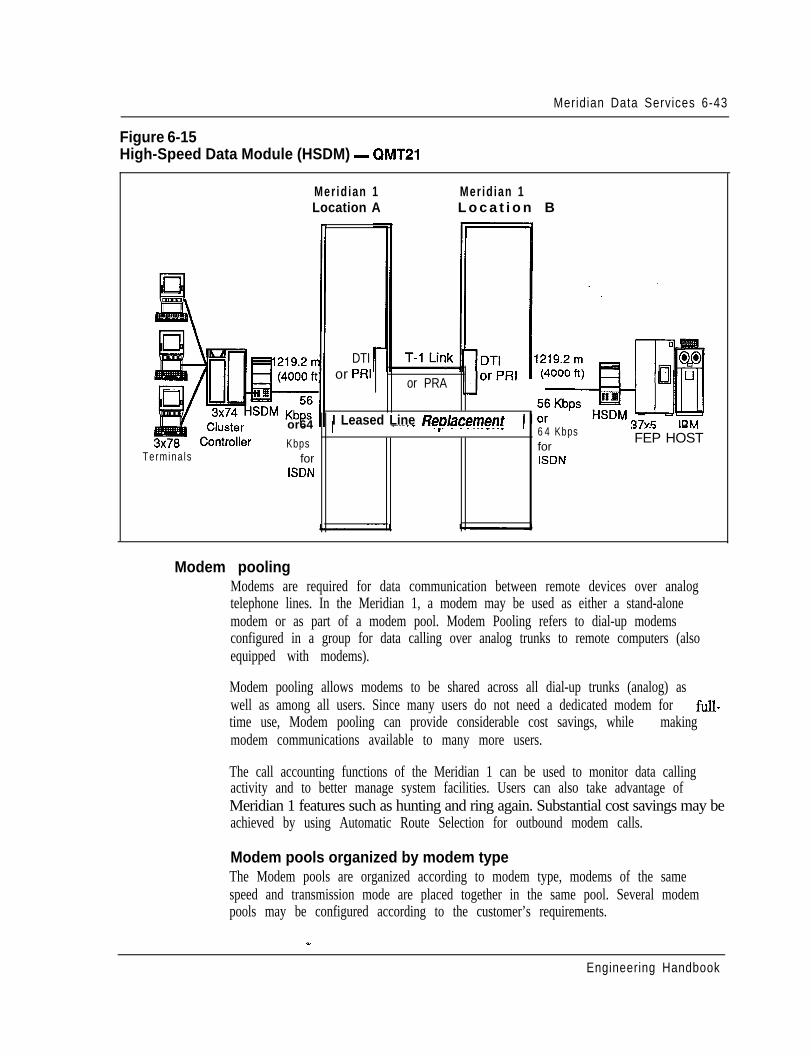
Meridian Data Services 6-43
Figure 6-15High-Speed Data Module (HSDM) - QMT21
Merid ian 1 Mer id ian 1Location A L o c a t i o n B
DTIor PRI
or PRA
I Leased Line Redacement I I
Termina ls
or64 1 -...- ..-r.--- .______ 16 4 Kbps
-. ..- .-...
Kbps forFEP HOST
for ISDNISDN
Modem poolingModems are required for data communication between remote devices over analogtelephone lines. In the Meridian 1, a modem may be used as either a stand-alonemodem or as part of a modem pool. Modem Pooling refers to dial-up modemsconfigured in a group for data calling over analog trunks to remote computers (alsoequipped with modems).
Modem pooling allows modems to be shared across all dial-up trunks (analog) aswell as among all users. Since many users do not need a dedicated modem for full-time use, Modem pooling can provide considerable cost savings, while makingmodem communications available to many more users.
The call accounting functions of the Meridian 1 can be used to monitor data callingactivity and to better manage system facilities. Users can also take advantage ofMeridian 1 features such as hunting and ring again. Substantial cost savings may beachieved by using Automatic Route Selection for outbound modem calls.
Modem pools organized by modem typeThe Modem pools are organized according to modem type, modems of the samespeed and transmission mode are placed together in the same pool. Several modempools may be configured according to the customer’s requirements.
Engineering Handbook
6-44 Meridian Data Services
Outbound/inbound modem poolingOutbound modem pools provide shared access to remote data environments forterminal and personal computer users. Inbound modem pools provide shared accessto Meridian 1 data services for remote term@1 and workstation users. Modempools can be configured in a variety of ways depending on the individualrequirements. If “smart” modems are utilized with the RILC, inbound and outboundmodem pools can be configured using the same modems, significantly reducinghardware requirements. Modem pools can also be configured separately.
Placing a modem pool callThe user places a remote data call by keyboard dialing to the modem pool DN(Directory Number) through the use of a communications software package. TheMeridian 1 reserves a modem for the call, prompts the user for the telephonenumber of the far-end modem, and instructs the reserved modem to place the call.
Modem pooling hardware, wiring and interface cardsA number of different configurations exist for connecting a modem pool to theMeridian 1. A standard configuration is to set the smart modems up in both aninbound and outbound mode reducing the need for additional hardware. In thisconfiguration, The RILC must be configured as an SL-1 set only. When the RILCis programmed as an SL-1 set, the 1 station hunting for the outbound modem accessshould be in the opposite direction to the 500/2500 station hunting for the inboundmodem access.
A standard way to connect modems to the Meridian -1 would be to connect the PBXto a Main Distribution Frame (MDF) from which a patch panel or octopus cable canbe COMeCted. These wiring schemes provide the high density cabling required forthe modem pool configuration. (See diagrams).
Engineering Handbook
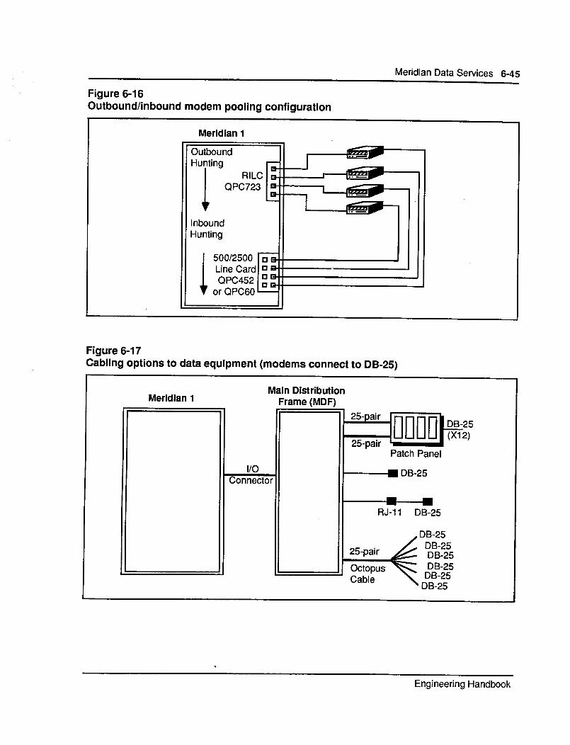
6-46 Meridian Data Services
Digital Trunk Interface (DTI) QPC471, QPC472Digital Trunk Interface (DTI) extends the capabilities of the Meridian 1 to allowdigital wide area voice and data service. The user with multiple locations can createa single all-digital network, by utilizing Digital Trunk Interface with T-l carriercommunications links.
Reduced costs with cleaner, faster transmissionThe primary benefit of DTI is to substantially reduce costs, but DTI also providescleaner and much higher speed data transmission than is possible using analogtrlmks.
North American T-lIn keeping with Northern Telecom commitment to OPEN WORLD, DTI uses theNorth American industry standard T-l interface, with the DS-1 signaling format.North American T-l carrier uses a 1.544 Mbps circuit, subdivided into 24 individualchannels which can be used for either digital voice or data communications.
24 channels of 56 KbpsEach of these 24 channels can support synchronous transmission up to 56 Kbps orasynchronous transmission up to 19.2 Kbps.
Voice or data transmissionEach DTI link can be configured to carry all voice, all data, or a mixture of voiceand data. Each channel may also be programmed independently for various digitaltrunk configurations (CO trunks, FX trunks, etc.).
Systems supportedDTI can be used to communicate voice and data between Meridian 1 systems . DTIcan also be used to connect the Meridian 1 to any PBX or Central Office with asuitable T- 1 interface.
System requirementsThe software associated with DTI must be Generic Xl 1 Release 5 or later and mustinclude software option 75 (PBX Interface).
Hardware configurationDTI consists of two circuit packs:
- -- QPC471- Clock Controller (maximum 2 per system) 2- QPC472/720 - Digital Trunk or Primary Rate Interface (PRI)
InterfaceThe DTI circuit pack uses 2 card slots and is typically located on a Network Shelf.The clock controller is located on the network module of the Meridian 1 Systemoption 5 l/6 1 and on the CPU module of the Meridian 1 System option 7 1. The
Engineering Handbook
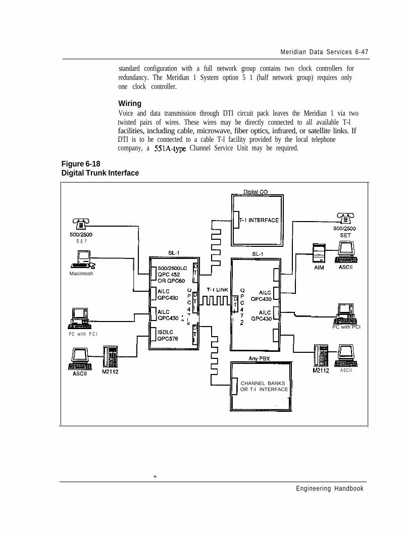
Meridian Data Services 6-47
standard configuration with a full network group contains two clock controllers forredundancy. The Meridian 1 System option 5 1 (half network group) requires onlyone clock controller.
WiringVoice and data transmission through DTI circuit pack leaves the Meridian 1 via twotwisted pairs of wires. These wires may be directly connected to all available T-lfacilities, including cable, microwave, fiber optics, infrared, or satellite links. IfDTI is to be connected to a cable T-l facility provided by the local telephonecompany, a 551A-type Channel Service Unit may be required.
Figure 6-18Digital Trunk Interface
S E T
Macintosh
1 I lJQPC430 : I I II : QPC43041 -
P C w i t h P C IPC with PCI
CHANNEL BANKSOR T-l INTERFACE
II
M2112 A S C I I
Engineering Handbook
6-48 Meridian Data Services
Primary Rate Access (PRA)Meridian ISDN Primary Rate Access (PRA) stimulates development of newapplications that fully utilize ISDN networking services. With added capabilitiessuch as integrated voice and data, network-wide feature transparency, andinterworking with host computer databases, ISDN PRA provides a platform forinnovative networking services.
The following feature rich enhancements enable advanced applications that providethe opportunity to substantially improve worker productivity:- conducting simultaneous voice and data teleconferencing- activating Ring Again or Call Forwarding across a network- notification of a calling party’s identity- improving telemarketing and order entry by automatically linking the calling
party’s number to a file in a host computer database- centralizing message services or call detail recording for many locations
ISDN can be added to your Meridian 1 with the simple addition of two circuit packsand selected software options.
Primary Rate Interface (PRI) - (QPC720)The Primary Rate Interface (PRI) circuit pack is a new line card that provides a1 S44 Mbps 24 channel digital link from the Meridian 1 to public and privatenetworks. The PRI allows twenty-four 64 Kbps clear channels, including a 64 Kbpsout-of-band signaling channel (23B+D). It can also be configured to support T- 1facility access, including Extended Super Frame.
D-Channel Handler Interface (DCHI) - (QPC757)The D-Channel Handler Interface (DCHI) is a new line card that processes ISDNsignaling information on the out-of-band signaling channel for basic call connectionservices such as call set-up, tear down, and feature activation. It implements theCCITT defined ISDN LAP-D link layer protocols. The DCHI also provides a singleasynchronous Serial Data Interface (SDI) port.
Xl 1 Release 13 softwareXl 1 Release 13 software (and later versions) contains the instructions forinterpreting Q.931 signaling on the D-channel. 4.931 is the signaling protocolrecommended by the CCITT for ISDN Primary Rate Access. It-acts in unison withthe DCHI card to switch and route data between devices. ’
Meridian 1 software featuresMeridian 1 software options 117, 118, 145149 are the feature packages whichprovide user access to enhanced ISDN services (basic call connection features,network calling services, enhanced trunking, and integrated voice and data).
Engineering Handbook
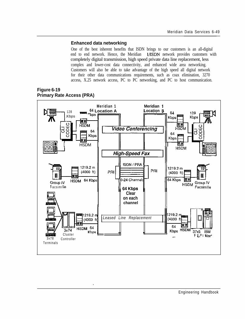
Meridian Data Services 6-49
Enhanced data networkingOne of the best inherent benefits that ISDN brings to our customers is an all-digitalend to end network. Hence, the Meridian l/ISDN network provides customers withcompletely digital transmission, high speed private data line replacement, lesscomplex and lower-cost data connectivity, and enhanced wide area networking.Customers will also be able to take advantage of the high speed all digital networkfor their other data communications requirements, such as coax elimination, 3270access, X.25 network access, PC to PC networking, and PC to host communication.
Figure 6-19Primary Rate Access (PRA)
Merid ian 1 Meridian 1128 II 64 Location AKbps “’
Location E3 -.
!I I HSDM 1 II II II w II;
Facs imr
PRI
Clearon eachchannel
Leased Line Replacement
I Clus te r C C D UP.-+3x78
I LI I ,“a,Cont ro l le r
_-
Termina ls
. .
Engineering Handbook
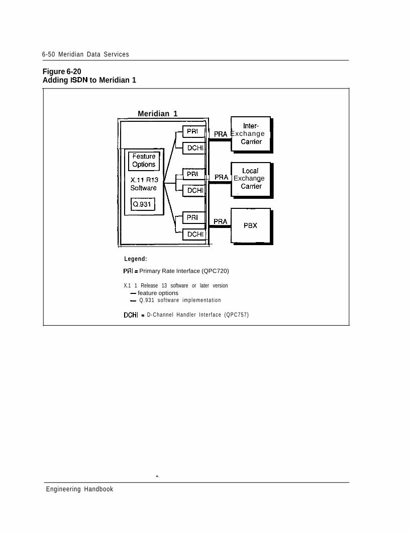
6-50 Meridian Data Services
Figure 6-20Adding ISDN to Meridian 1
Meridian 1
PRA Exchange
. PRA Exchange
Legend:
PRI = Primary Rate Interface (QPC720)
X.1 1 Release 13 software or later version- feature options- Q.931 so f tware imp lementa t ion
DCHI = D-Channe l Hand ler In te r face (QPC757)
Engineering Handbook
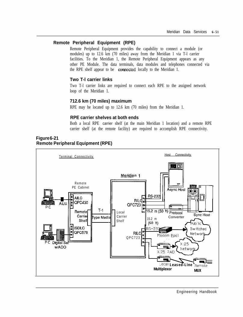
Meridian Data Services 6-51
Remote Peripheral Equipment (RPE)Remote Peripheral Equipment provides the capability to connect a module (ormodules) up to 12.6 km (70 miles) away from the Meridian 1 via T-l carrierfacilities. To the Meridian 1, the Remote Peripheral Equipment appears as anyother PE Module. The data terminals, data modules and telephones connected viathe RPE shelf appear to be COMeCted locally to the Meridian 1.
Two T-l carrier linksTwo T-l carrier links are required to connect each RPE to the assigned networkloop of the Meridian 1.
712.6 km (70 miles) maximumRPE may be located up to 12.6 km (70 miles) from the Meridian 1.
RPE carrier shelves at both endsBoth a local RPE carrier shelf (at the main Meridian 1 location) and a remote RPEcarrier shelf (at the remote facility) are required to accomplish RPE connectivity.
Figure 6-21Remote Peripheral Equipment (RPE)
Termina l Connec t i v i t y Host Connectivity
R e m o t ePE Cabinet
AILCQPC430 II
Meridian 1
:i
RILCB.. I- WI
QPC723 c-P’ c . . . - 1
Loca l - 15.2 m (50 fi) protocol L-l-JCarr ierShe l f 15.2 m
(50 fi)
Converter x
RILCQ P C 7 2 3
Local Leased-Line RemoleMultiplexor MUX
Engineering Handbook
6-52 Meridian Data Services
Strategic Alliances ProgramCustomers demand that the information industry connect equipment from varioussuppliers to provide applications in a multi-vendor;multi-media environment.Customers want to have the ability to handle any form of information - voice, data,text, graphics and image.
Northern Telecom initiated the Strategic Alliances Program in 1982 to encourageclose working relationships with leading computer vendors. Northern has developedand maintained these partnerships to jointly deliver benefits to customers by servingtheir needs for innovative integrated information systems involving many types ofequipment, from multiple vendors.
As a part of its efforts, Northern Telecom Strategic Alliances Program conductsongoing connectivity testing with its partners. Northern Telecom connectivitytesting program is designed to provide customers with a wide range of tested,effective connections for a variety of applications.
By providing compatibility with multiple computer and connectivity products, theMeridian 1 can accommodate new requirements in a cost-effective manner.
Apple Computer, Inc.Apple Computer is one of the largest manufacturers of personal computerworkstations. Featuring a broad range of configurations and applications, and greatease of use, Apple Macintosh family of 32-bit computers has been embraced bybusiness and education. Through a cooperative working agreement, NorthernTelecom and Apple Computer are committed to the testing and integration ofMacintosh technology with the Meridian 1.
The Macintosh has access to MS-DOS or other Macintosh personal computers (bothstandalone and networked) for data exchange and file transfer. In addition, theMacintosh connects to asynchronous host computers, modem pools, IBM hosts viaprotocol converters and to X.25 gateways, all through the Meridian 1. In anasynchronous environment, speeds up to 19.2 Kbps are supported; in a synchronousenvironment, speeds up to 64 Kbps may be attained.
Northern Telecom Memory Systems Division offers Memorybank, a hard disksubsystem with SCSI interface to Macintosh. With storage capacity up to fiveGigabytes, Memorybank is ideal for Local Area Networks. LANs interconnectedvia the Meridian 1 (see “Macintosh Connectivity” in this Chapter) can use theMemorybank system as a file or disk server.
Meridian 1 SL- 100 and DMS- 100 switches also support Macintosh connectivity viathe Datapath and Meridian Data Services product lines respectively.
Supported configurationsMacintosh 512K, Macintosh Plus, Macintosh SE, Macintosh II and any othermodels which have built-in RS-422 connections are supported.
G . .
Engineering Handbook
Meridian Data Services 6-53
Apple LaserWriter and Apple LaserWriter II printers may also be connected.Meridian SL Laser Printer Software provides for an unlimited number of Macintoshusers connected to the Meridian 1 to dial and print to Apple LaserWriter printersattached to the switch locally, via RPE, or cross-country without the need to use anAppleTalk connection or bridge. The LaserWriter connected to the Meridian 1 isselected via the Macintosh Chooser and is used by executing the standardMacintosh PRINT command from any application program.
Data modulesMacintosh Computers (RS-422) may be connected directly to the AILC card;through Digital Telephones with an ADO, or Modular Telephones with an MPDA.
AppleTalk LANs may be bridged via the Hayes Interbridge and the ASIM orHSDM. Macintoshes can dial into an AppleTalk network via a Solana R-Serverconnected to the RILC.
Apple LaserWriters are connected via the EAILU or a direct RS-422 connection.
Engineering Handbook
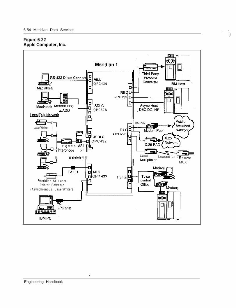
6-54 Meridian Data Services
Figure 6-22Apple Computer, Inc.
AILC;Q P C 4 3 0
ISIQ P C 5 7 8
I OcalTalk Netwcxls
LaserWriter IIm IIL!-+
Ihm qL 71 YLV
II
H a v e s ASIM qI&!- lnterdridge
@ .j QPC432
o r IF
s I - ����II
RS-232-
Leased-Line Ramnfe
II MultIplexor .-...-MUX
Mer id ian SL Laser “-ITrunks-
Pr in te r So f tware(Asynchronous LaserWr i te r ) I Ir I-r”@
IOll I Offici’ l&G3Jdem
Engineering Handbook
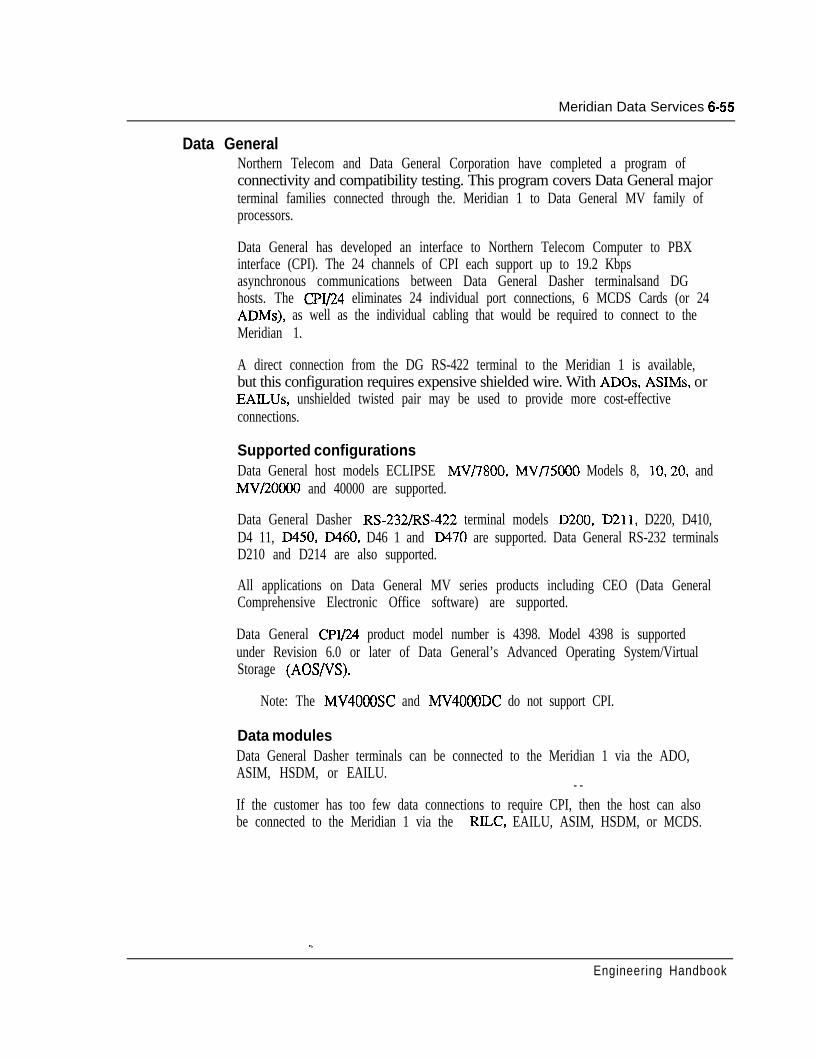
Meridian Data Services 6-55
Data GeneralNorthern Telecom and Data General Corporation have completed a program ofconnectivity and compatibility testing. This program covers Data General majorterminal families connected through the. Meridian 1 to Data General MV family ofprocessors.
Data General has developed an interface to Northern Telecom Computer to PBXinterface (CPI). The 24 channels of CPI each support up to 19.2 Kbpsasynchronous communications between Data General Dasher terminalsand DGhosts. The CPI/24 eliminates 24 individual port connections, 6 MCDS Cards (or 24ADMs), as well as the individual cabling that would be required to connect to theMeridian 1.
A direct connection from the DG RS-422 terminal to the Meridian 1 is available,but this configuration requires expensive shielded wire. With ADOS, ASIMs, orEAILUs, unshielded twisted pair may be used to provide more cost-effectiveconnections.
Supported configurationsData General host models ECLIPSE MV/7800, MV/75000 Models 8, 10,20, andMV/20000 and 40000 are supported.
Data General Dasher RS-232/RS-422 terminal models D200, D211, D220, D410,D4 11, D450, D460, D46 1 and D470 are supported. Data General RS-232 terminalsD210 and D214 are also supported.
All applications on Data General MV series products including CEO (Data GeneralComprehensive Electronic Office software) are supported.
Data General CPI/24 product model number is 4398. Model 4398 is supportedunder Revision 6.0 or later of Data General’s Advanced Operating System/VirtualStorage (AOS/VS).
Note: The MV40CMlSC and MV4000DC do not support CPI.
Data modulesData General Dasher terminals can be connected to the Meridian 1 via the ADO,ASIM, HSDM, or EAILU.
- -If the customer has too few data connections to require CPI, then the host can alsobe connected to the Meridian 1 via the RILC, EAILU, ASIM, HSDM, or MCDS.
Engineering Handbook
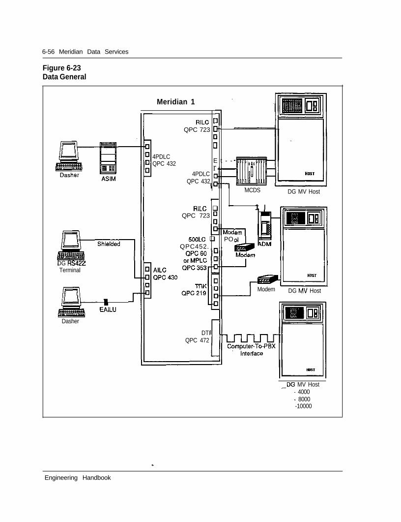
6-56 Meridian Data Services
Figure 6-23Data General
Meridian 1
4PDLCQPC 432
DG RS42,Terminal
Dasher
II
EAILU
RILC [QPC 723 tt-
Elil
E t - -r
4PDLC [QPC 432
MCDS DG MV Host-
RILC q - 1QPC 723 ;
5OOLC q POQPC452. -
IemiLLi4014DM
DTIQPC 472
Modem DG hIN Host
--DG MV Host- 4000- 8000-10000
Engineering Handbook
Meridian Data Services 6-57
Digital Equipment CorporationNorthern Telecom and Digital Equipment Corporation have completed a significantamount of product integration and testing. The result is a cost-effective andsimplified terminal to host connectivity through the Meridian 1.
To connect the Meridian 1 to the VAX, Northern Telecom recommends using theRS-232 Interface Line Card (RILC). The RILC allows cost-effective connectivityto the VAX by eliminating the need for the ASIM, HSDM and MCDS. The RILCmay be connected directly to the VAX Host or may be connected through DECEthernet Terminal Servers (DECServer 200 or 500).
Although the RILC eliminates the need for the ASIM, HSDM and MCDS, thesemodules may still be used for Meridian l/VAX connectivity. The ASIM andHSDM may be required if asynchronous host mode capability is required (see “DataServices Terminal Connectivity” in this Chapter).
Supported configurationsVAX hosts supported: VAX Series 8000,8600,8650, VAX Series 1 l/730,1 l/750and 1 l/780, 1 l/782, 1 l/785, MicroVAX 2000
Digital terminals, PCs and terminal servers supported: VTlOO, VT220, VT 340Series, DECmate II and III, Rainbow 100, Professional 300 and VAXmate,DECServer 200 and 500
Data modulesDEC terminals may be connected to the Meridian 1 using ASIM, HSDM, EAILU,or ADO.
The DEC hosts may be connected via the RILC, EAILU, ASIM, HSDM, or MCDS.
. .
Engineering Handbook
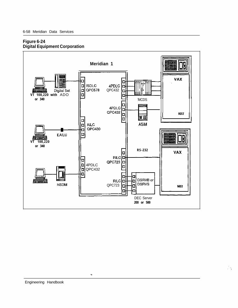
6-58 Meridian Data Services
Figure 6-24Digital Equipment Corporation
VT 100,220 with ADO
Meridian 1
or 340
VT 100,220or 340
4PDLCQPC432
MCDS
-ml-
ASIM
RILCQPC723
r-IIqRS-232
qn0 4PDLC0 QPC432
DEC Server200 or 500
Engineering Handbook
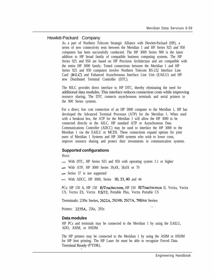
Meridian Data Services 6-59
Hewlett-Packard CompanyAs a part of Northern Telecom Strategic Alliance with Hewlett-Packard (HP), aseries of new connectivity tests between the Meridian 1 and HP Series 925 and 950computers has been successfully conducted. The HP 3000 Series 900 is the latestaddition to HP broad family of compatible business computing systems. The HPSeries 925 and 950 are based on HP Precision Architecture and are compatible withthe entire HP 3000 family. Tested connections between the Meridian 1 and HPSeries 925 and 950 computers involve Northern Telecom RS-232 Interface LineCard (RILC) and Enhanced Asynchronous Interface Line Unit (EAILU) and HPnew Distributed Terminal Controller (DTC).
The RILC provides direct interface to HP DTC, thereby eliminating the need foradditional data modules. This interface reduces connection costs while improvingresource sharing, The DTC connects asynchronous terminals and serial printers tothe 900 Series systems.
For a direct, low cost connection of an HP 3000 computer to the Meridian 1, HP hasdeveloped the Advanced Terminal Processor (ATP) for the Meridian 1. When usedwith a breakout box, the ATP for the Meridian 1 will allow the HP 3000 to beconnected directly to the AILC. HP standard ATP or Asynchronous DataCommunications Controller (ADCC) may be used to interface the HP 3000 to theMeridian 1 via the EAILU or MCDS. These connections expand options for jointusers of Meridian 1 Systems and HP 3000 systems who wish to lower costs,improve resource sharing and protect their investments in communication systems.
Supported configurationsHost:- With DTC, HP Series 925 and 950 with operating system 1.1 or higher- With ATP, HP 3000 Series 39,4X, 58,6X or 70- Series 37 is not supported- With ADCC, HP 3000, Series 30,33,40 and 44
PCs: HP 150 A, HP 150 B/I’ouchscreen, HP 150 IYI’ouchscreen II, Vectra, VectraCS, Vectra ES, Vectra ES/12, Portable Plus, Vectra Portable CS
Terminals: 239x Series, 2622A, 2624B, 2627A, 7OO/xx Series
Printers: 2235A, 256x, 293x - -
Data modulesHP PCs and terminals may be connected to the Meridian 1 by using the EAILU,ADO, ASIM, or HSDM.
The HP printers may be connected to the Meridian 1 by using the ASIM or HSDMfor HP host printing. The HP Laser Jet must be able to recognize Forced DataTerminal Ready (FIDR).
v..
Engineering Handbook
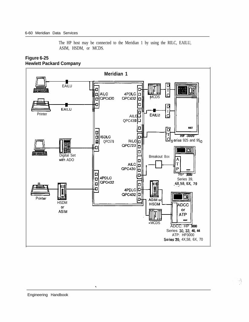
6-60 Meridian Data Services
The HP host may be connected to the Meridian 1 by using the RILC, EAILU,ASIM, HSDM, or MCDS.
Figure 6-25Hewlett Packard Company
Meridian 1II
EAILU
Printer
n
Digital Setwith ADO
JEt
AIL qQPC430 q
10c] ISDLCq QPC578
HSDM
A:M
MCDS
Breakout
--El-
Box
HP 3000‘cries 925 and 95
HP 3000Series 39,
4X.58,6X, 7 0
MCDSADCC: HP 3000
Series 30,33, 40, 44ATP: HP3000
Series39, 4X,58, 6X, 70
Engineering Handbook
Meridian Data Services 6-61
NCRNorthern Telecom and NCR have completed joint connectivity testing of the NCRTower XP and NCR PC with the Meridian 1.
An NCR PC or an IBM PC may be connected to the Meridian 1 via the PC1 card.VT102 terminals may also be connected via an ADO or EAILU. The NCR TowerXP may be connected to the Meridian 1 via an ASIM, HSDM, or an EAILU.
These connections support access to modem pools, host computers, terminals, andX.25 PADS. File transfer from IBM PC to NCR Tower XP and file access to NCRTower XP (both via PC based communication software) are also supported.
Supported configurationsHost: NCR Tower XP
PCs and Terminals: NCR PC, VT102, IBM PC
Data modulesNCR PC and IBM PC may be connected via the PC1 card, EAILU, or ADO. VT102Terminals connect via an EAILU.
The NCR Tower may be connected to an RILC, EAILU, ASIM, or HSDM.
Engineering Handbook
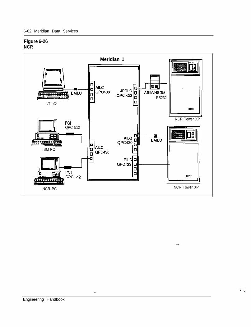
6-62 Meridian Data Services
Figure 6-26NCR
Meridian 1
VT1 02
PCIQPC 512
--l
IBM PC
l.-3
AILC 0”QPC430 m
J--EI RIASIM/HSDM
RS232
I 1NCR Tower XP
HOST
1-1
NCR PC NCR Tower XP
Engineering Handbook
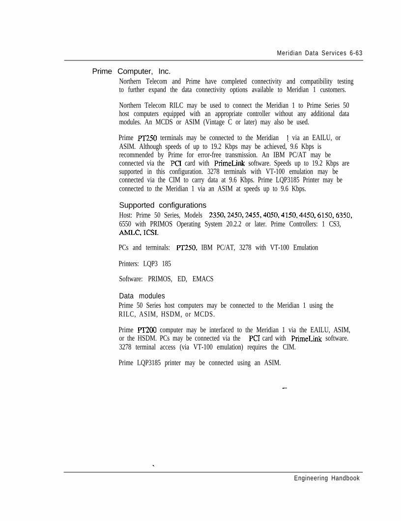
Meridian Data Services 6-63
Prime Computer, Inc.Northern Telecom and Prime have completed connectivity and compatibility testingto further expand the data connectivity options available to Meridian 1 customers.
Northern Telecom RILC may be used to connect the Meridian 1 to Prime Series 50host computers equipped with an appropriate controller without any additional datamodules. An MCDS or ASIM (Vintage C or later) may also be used.
Prime PT250 terminals may be connected to the Meridian 1 via an EAILU, orASIM. Although speeds of up to 19.2 Kbps may be achieved, 9.6 Kbps isrecommended by Prime for error-free transmission. An IBM PC/AT may beconnected via the PC1 card with PrimeLink software. Speeds up to 19.2 Kbps aresupported in this configuration. 3278 terminals with VT-100 emulation may beconnected via the CIM to carry data at 9.6 Kbps. Prime LQP3185 Printer may beconnected to the Meridian 1 via an ASIM at speeds up to 9.6 Kbps.
Supported configurationsHost: Prime 50 Series, Models 2350,2450,2455,4050,4150,4450,6150,6350,6550 with PRIMOS Operating System 20.2.2 or later. Prime Controllers: 1 CS3,AMLC, ICSI.
PCs and terminals: PT250, IBM PC/AT, 3278 with VT-100 Emulation
Printers: LQP3 185
Software: PRIMOS, ED, EMACS
Data modulesPrime 50 Series host computers may be connected to the Meridian 1 using theRILC, ASIM, HSDM, or MCDS.
Prime PT2OO computer may be interfaced to the Meridian 1 via the EAILU, ASIM,or the HSDM. PCs may be connected via the PC1 card with PrimeLink software.3278 terminal access (via VT-100 emulation) requires the CIM.
Prime LQP3185 printer may be connected using an ASIM.
-
Engineering Handbook
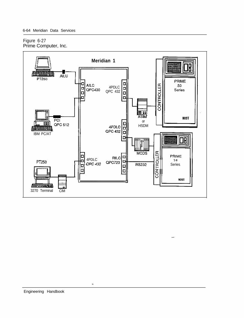
6-64 Meridian Data Services
Figure 6-27Prime Computer, Inc.
InI Meridian 1
4PDLCQPC 432
WM
+
7
c orADnIP -
1““‘“ldII HSDM
QPC432jl;,,IBM PC/AT
PT2504PDLCnor AQQ
3270 Terminal CIM
6 50
ESeries
I ’
Engineering Handbook
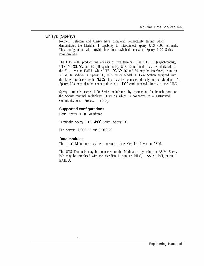
Meridian Data Services 6-65
Unisys (Sperry)Northern Telecom and Unisys have completed connectivity testing whichdemonstrates the Meridian 1 capability to interconnect Sperry UTS 4000 terminals.This configuration will provide low cost, switched access to Sperry 1100 Seriesmainframes.
The UTS 4000 product line consists of five terminals: the UTS 10 (asynchronous),UTS 20,30,40, and 60 (all synchronous). UTS 10 terminals may be interfaced tothe SL- 1 via an EAILU while UTS 20,30,40 and 60 may be interfaced, using anASIM. In addition, a Sperry PC, UTS 30 or Model 30 Desk Station equipped withthe Line Interface Circuit (LIC) chip may be connected directly to the Meridian 1.Sperry PCs may also be connected with a PC1 card attached directly to the AILC.
Sperry terminals access 1100 Series mainframes by contending for branch ports onthe Sperry terminal multiplexer (T-MUX) which is connected to a DistributedCommunications Processor (DCP).
Supported configurationsHost: Sperry 1100 Mainframe
Terminals: Sperry UTS 4000 series, Sperry PC
File Servers: DOPS 10 and DOPS 20
Data modulesThe 1100 Mainframe may be connected to the Meridian 1 via an ASIM.
The UTS Terminals may be connected to the Meridian 1 by using an ASIM. SperryPCs may be interfaced with the Meridian 1 using an RILC, ASIM, PCI, or anEAILU.
Engineering Handbook
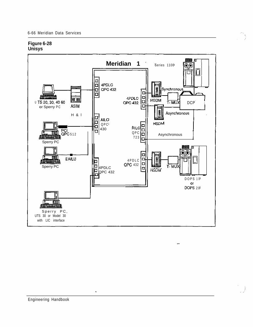
6-66 Meridian Data Services
Figure 6-28Unisys
U
Meridian 1 - Ser ies 1100
or Sperry P C ASIM
H & l
5 1 2
Sperry PC
Sperry PC
DCP I
;; AILCQ P C
; 430 RILC ;rll
HSDF
Q P C7 2 3
41 Asynchronous ]
7cl 4 P D L C
o 4PDLCQPC 432
n QPC 432 I-DUM
D O P S 1 0
DO;; 2 0
S p e r r y P C ,UTS 30 or Model 30
with LIC interface
--
Engineering Handbook
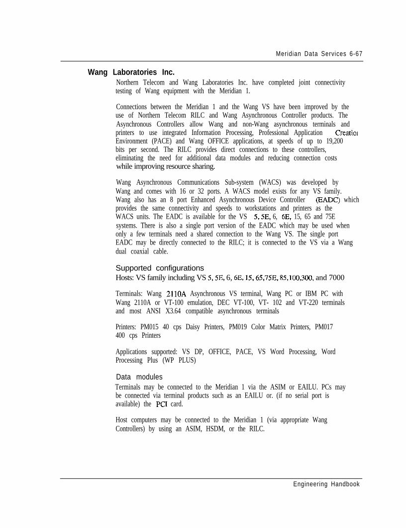
Meridian Data Services 6-67
Wang Laboratories Inc.Northern Telecom and Wang Laboratories Inc. have completed joint connectivitytesting of Wang equipment with the Meridian 1.
Connections between the Meridian 1 and the Wang VS have been improved by theuse of Northern Telecom RILC and Wang Asynchronous Controller products. TheAsynchronous Controllers allow Wang and non-Wang asynchronous terminals andprinters to use integrated Information Processing, Professional Application CreationEnvironment (PACE) and Wang OFFICE applications, at speeds of up to 19,200bits per second. The RILC provides direct connections to these controllers,eliminating the need for additional data modules and reducing connection costswhile improving resource sharing.
Wang Asynchronous Communications Sub-system (WACS) was developed byWang and comes with 16 or 32 ports. A WACS model exists for any VS family.Wang also has an 8 port Enhanced Asynchronous Device Controller (EADC) whichprovides the same connectivity and speeds to workstations and printers as theWACS units. The EADC is available for the VS 5,5E, 6, 6E, 15, 65 and 75Esystems. There is also a single port version of the EADC which may be used whenonly a few terminals need a shared connection to the Wang VS. The single portEADC may be directly connected to the RILC; it is connected to the VS via a Wangdual coaxial cable.
Supported configurationsHosts: VS family including VS 5,5E, 6, 6E, 15,65,75E, 85,100,300, and 7000
Terminals: Wang 2llOA Asynchronous VS terminal, Wang PC or IBM PC withWang 2110A or VT-100 emulation, DEC VT-100, VT- 102 and VT-220 terminalsand most ANSI X3.64 compatible asynchronous terminals
Printers: PM015 40 cps Daisy Printers, PM019 Color Matrix Printers, PM017400 cps Printers
Applications supported: VS DP, OFFICE, PACE, VS Word Processing, WordProcessing Plus (WP PLUS)
Data modulesTerminals may be connected to the Meridian 1 via the ASIM or EAILU. PCs maybe connected via terminal products such as an EAILU or. (if no serial port isavailable) the PC1 card.
Host computers may be connected to the Meridian 1 (via appropriate WangControllers) by using an ASIM, HSDM, or the RILC.
Engineering Handbook
6-68 Meridian Data Services
Figure 6-29Wang Laboratories, Inc.
with AlX3
’ ISDLC0 WCE 587-
9’ 4PDLC’ QPC432
Meridian 1
HSDM
RILC iQPC q723 D -
-
RILC ;QPC q723 D
vs1
WACS u IS/IO
(16 or 32 ports) -
I _ Local Terminal
VS-EADC-1 Portr
Engineering Handbook
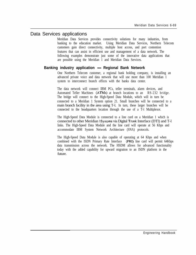
Meridian Data Services 6-69
Data Services applicationsMeridian Data Services provides connectivity solutions for many industries, frombanking to the education market. Using Meridian Data Services, Northern Telecomcustomers gain direct connectivity, multiple host access, and port contentionfeatures that can assist in efficient use and management of a data network. Thefollowing examples demonstrate just some of the innovative data applications thatare possible using the Meridian 1 and Meridian Data Services.
Banking industry application - Regional Bank NetworkOne Northern Telecom customer, a regional bank holding company, is installing anadvanced private voice and data network that will use more than 100 Meridian 1system to interconnect branch offices with the banks data center.
The data network will connect IBM PCs, teller terminals, alarm devices, andAutomated Teller Machines (ATMs) at branch locations to an RS-232 bridge.The bridge will connect to the High-Speed Data Module, which will in turn beconnected to a Meridian 1 System option 21. Small branches will be connected to amain branch facility in the area using T-l. In turn, these larger branches will beconnected to the headquarters location through the use of a T-l Multiplexor.
The High-Speed Data Module is connected to a line card on a Meridian 1 which isconnected to other Meridian 1Systems via Digital Trunk Interface (DTI) and T-llinks. The High-Speed Data Module and the line card will operate at 56 Kbps andaccommodate IBM System Network Architecture (SNA) protocols.
The High-Speed Data Module is also capable of operating at 64 Kbps and whencombined with the ISDN Primary Rate Interface (PRI) line card will permit 64Kbpsdata transmission across the network. The HSDM allows for advanced functionalitytoday with the added capability for upward migration to an ISDN platform in thefuture.
Engineering Handbook
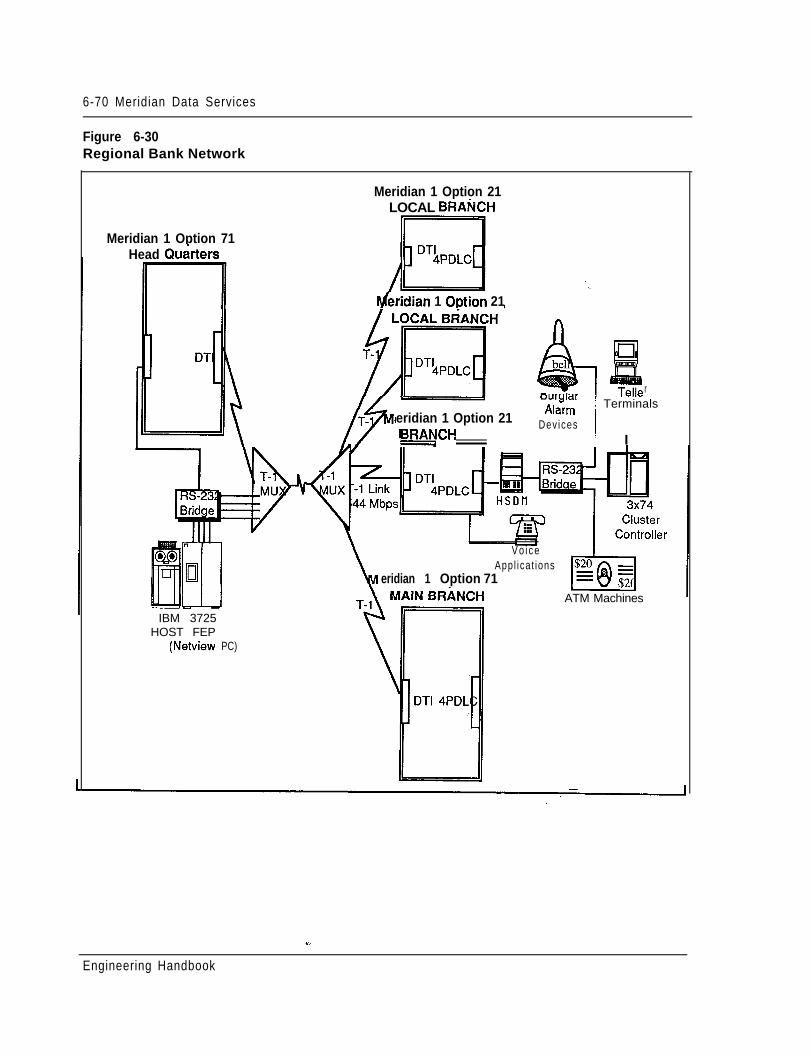
6-70 Meridian Data Services
Figure 6-30Regional Bank Network
Meridian 1 Option 71Head Qu&ters
IBM 3725HOST FEP
(Netview PC)
Meridian 1 Option 21LOCAL BRANCH
IYferidian 1 Option 21
rourglarA I^“.- 1 Terminals
eridian 1 Option 21nlallll
t;OCALBRAEjCHDev ices
I I
ATM Machines
V o i c eAppl icat ions
eridian 1 Option 71
Engineering Handbook
Meridian Data Services 6-71
University application - Eastern College NetworkAt a leading Northeastern college progressive philosophy in preparing young peoplefor contemporary life is evident from the extensive use of a variety of dataprocessing equipment throughout the college.
Voice and data communications are provided by a Northern Telecom SL- 1.Computing power for the college is provided by Digital VAX computers, an IBM3090, and about 1000 Macintosh and MS-DOS personal computers. UsingMeridian Data Services, all of these systems have been tied together in a broad andvaried data network allowing almost every course at the college to involve acomputer in some way. The SL-1 provides switched access to a variety ofcomputing resources; some examples are provided below.
Business learning lab - Many Macintosh systems are used to access businesssimulations located on a host computer.. Macintoshes are connected to the hostthrough the SL- 1, eliminating the need for modems and point-to-point dedicatedconnections through existing wiring and direct RS-422 connections.
Faculty and administrative staff both need to access student records, student work,and business information on computers in several locations. The SL- 1 providesswitched access to specific hosts located on campus. Computer workstationsanywhere on campus can reach the hosts by simply entering the appropriate phonenumber.
Meridian Data Services reduces the number of DEC VAX host ports and dedicatedterminals that are needed through use of the MCDS and port contention and featuressuch as Hotline and Ring Again. For the same reason, a smaller number of protocolconverters are needed for access to IBM mainframes.
Meridian SL Laser Printer Software automatically connects a Macintosh to anylocal or remote LaserWriter selected from the Macintosh Chooser, while using anyMacintosh application. Each LaserWriter is connected to the switch, via RS-422directly or through an EAILU.
This college represents advanced collegiate teaching techniques using the followingadvanced tools and Northern Telecom communications equipment.- Host interface applications- File transfers- HyperCard simulations
- -
Engineering Handbook
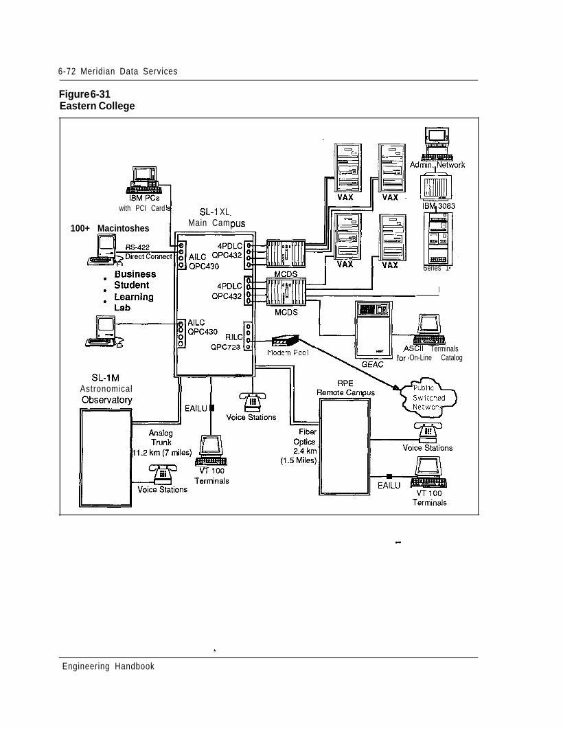
6-72 Meridian Data Services
Figure 6-31Eastern College
with PCI Card
100+ Macintoshes
SL-1 XLMain Cam
Series 1
I
nAll TerminalsOn-Line Catalog
Astronomical
--
Engineering Handbook
Meridian Data Services 6-73
Aerospace industry application -defense contractorAnother Northern Telecom customer, a leader in aerospace and advancedgovernment systems including the Space Shuttle and the Strategic Defense Initial(SDI), needed a reliable data network that would connect a variety of users to avariety of computers. This company chose a Meridian 1 and Meridian DataServices to provide for their diverse data networking needs.
ve
The Meridian 1 connects over two hundred users from different project groupswithin me Software Center of Excellence (SCOE) Lab to different computers suchas DEC VAXs, Data Generals, Sequents, Symbolics, and MS-DOS and Macintoshpersonal computers. The Northern Telecom Meridian network provides reducedmoving and changing costs and improved implementation time of moves. With theMeridian 1 port contention capability, both casual and heavy user can beaccommodated efficiently and cost effectively.
An Ethernet LAN using Bridge Communications servers is connected to theMeridian 1 with 32 direct RS-232 port connections per server. The Meridian 1connection enables terminals and PCs not directly connected to the Ethernet LAN togain switched access to the network, a much more cost-effective connection forusers not requiring dedicated access. The Ethernet LAN provides PCs (both IBMand Macintosh computers) high speed access to scientific systems, including SUN,Sequent and Symbolics computers.
Data access modules designed to support varying transmission requirements forterminal and host connectivity are used at this company.
Asynchronous/Synchronous Interface Modules (ASIMs) are used to connectterminals within the engineering group to the Meridian 1. Those with MS-DOSpersonal computers use the Personal Computer Interface Card (PCI) to connect.Macintosh users gain access to the Meridian 1 through the use of an RS-422 directconnection. The direct connection further reduces communication costs andsimplifies hardware requirements.
The contractor uses an ADM connected to a 3270 protocol converter to provideaccess to a remote host computer which houses an electronic mail system forexecutives.
This defense contractor, with the flexibility, the reliability, and the cost savings ofadvanced technology provided by the Northern Telecom Meridian 1, stands at thethreshold of exciting technological innovations. ,
Engineering Handbook
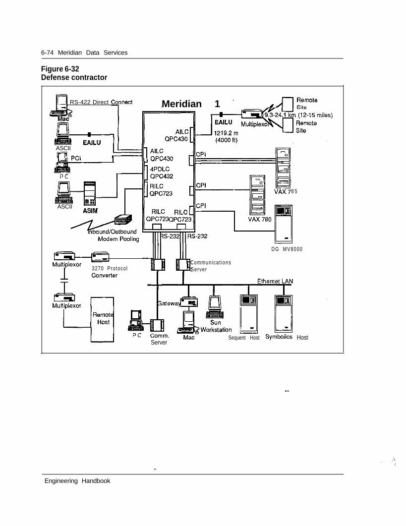
6-74 Meridian Data Services
Figure 6-32Defense contractor
m RS-422 Direct Cqnnect Meridian 1 -
,I IIASCII
ASCIIASIM
k=lh AILC
8 5
DG MV8000
3270 Protoco lCommunica t ionsServer
ServerSequent Host Symbolics Host
-
Engineering Handbook
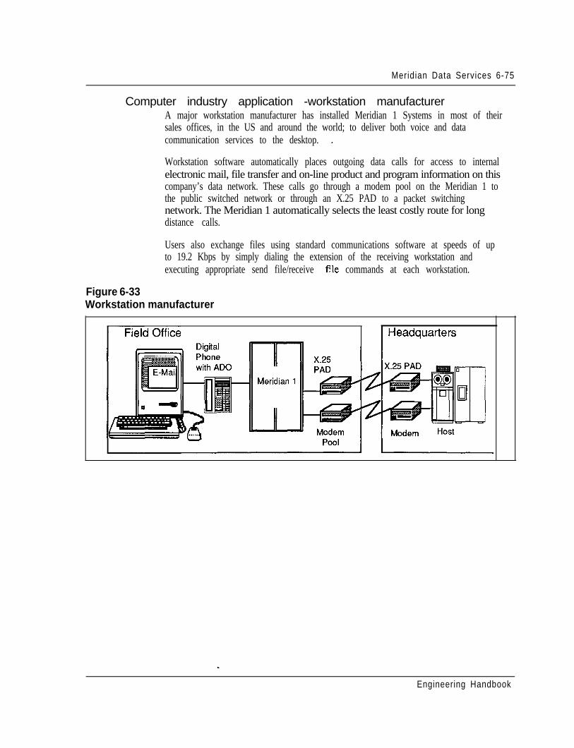
Meridian Data Services 6-75
Computer industry application -workstation manufacturerA major workstation manufacturer has installed Meridian 1 Systems in most of theirsales offices, in the US and around the world; to deliver both voice and datacommunication services to the desktop. -
Workstation software automatically places outgoing data calls for access to internalelectronic mail, file transfer and on-line product and program information on thiscompany’s data network. These calls go through a modem pool on the Meridian 1 tothe public switched network or through an X.25 PAD to a packet switchingnetwork. The Meridian 1 automatically selects the least costly route for longdistance calls.
Users also exchange files using standard communications software at speeds of upto 19.2 Kbps by simply dialing the extension of the receiving workstation andexecuting appropriate send file/receive file commands at each workstation.
Figure 6-33Workstation manufacturer
Engineering Handbook
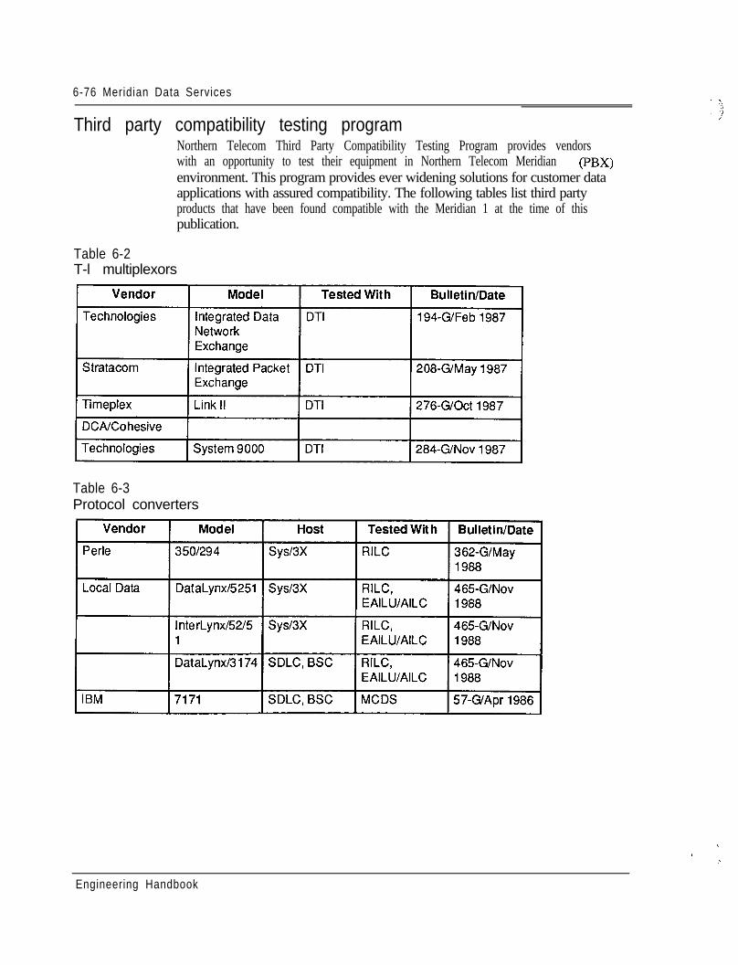
6-76 Meridian Data Services
Third party compatibility testing programNorthern Telecom Third Party Compatibility Testing Program provides vendorswith an opportunity to test their equipment in Northern Telecom Meridian (PBX)environment. This program provides ever widening solutions for customer dataapplications with assured compatibility. The following tables list third partyproducts that have been found compatible with the Meridian 1 at the time of thispublication.
Table 6-2T-l multiplexors
Table 6-3Protocol converters
\
,
.I
Engineering Handbook
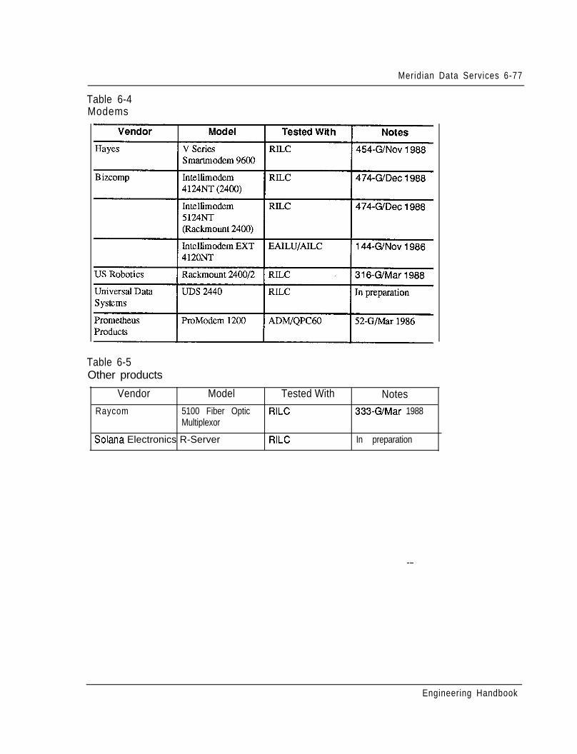
Meridian Data Services 6-77
Table 6-4Modems
Table 6-5Other products
Vendor Model Tested With NotesRaycom 5100 Fiber Optic RILC 333GMar 1988
Multiplexor
Solana Electronics R-Server RILC In preparation
Engineering Handbook
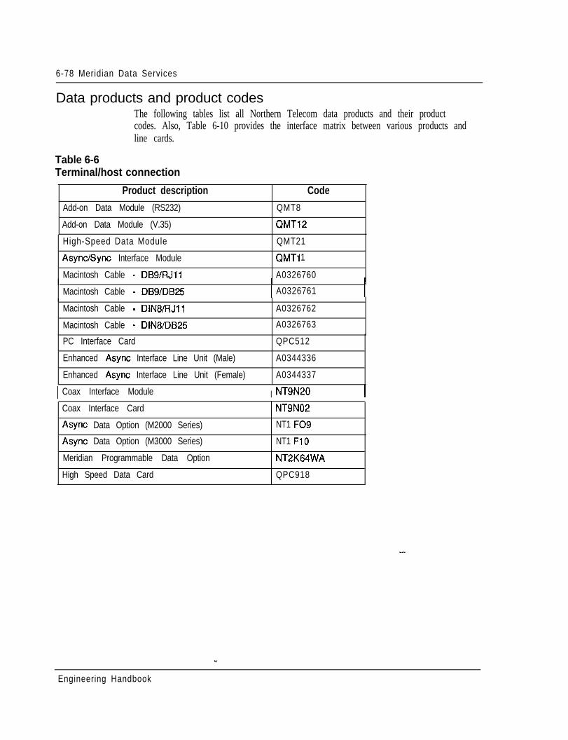
6-78 Meridian Data Services
Data products and product codesThe following tables list all Northern Telecom data products and their productcodes. Also, Table 6-10 provides the interface matrix between various products andline cards.
Table 6-6Terminal/host connection
Product description CodeAdd-on Data Module (RS232) QMT8
Add-on Data Module (V.35) QMT12
High-Speed Data Module
Async/Sync Interface Module
Macintosh Cable - DBS/RJll
Macintosh Cable - DB9/DB25
Macintosh Cable - DIN8/RJll
Macintosh Cable - DlN8/DB25
QMT21
QMTi 1
A0326760I1 A0326761 I
A0326762
A0326763
PC Interface Card
Enhanced Async Interface Line Unit (Male)
Enhanced Async Interface Line Unit (Female)
QPC512
A0344336
A0344337
I Coax Interface Module I NT9N20 ICoax Interface Card
Async Data Option (M2000 Series)
NT9N02
NT1 FO9
Async Data Option (M3000 Series)
Meridian Programmable Data Option
High Speed Data Card
NT1 FlO
NT2K64WA
QPC918
Engineering Handbook
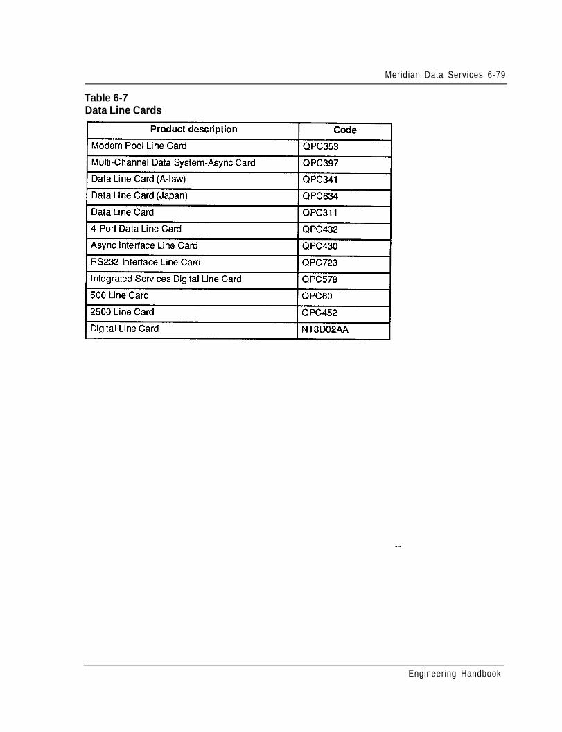
Meridian Data Services 6-79
Table 6-7Data Line Cards
Engineering Handbook
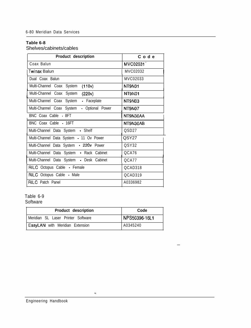
6-80 Meridian Data Services
Table 6-8Shelves/cabinets/cables
Product description C o d e
Coax Balun MVC02031-
1 Twinax Balun 1 MVC02032
Dual Coax Balun
Multi-Channel Coax System (110~)
Multi-Channel Coax System (220~)
MVC02033
NTSNOiI
1 NT9NOl
Multi-Channel Coax System - Faceplate NT9N03
Multi-Channel Coax System - Optional Power NT9N07I
BNC Coax Cable - 8FT 1 NT9N30AA I
BNC Coax Cable - 16FT
Multi-Channel Data System - Shelf
Multi-Channel Data System - 11 Ov Power
NT9N30AB
QSD27I
1 QSY27 IMulti-Channel Data System - 220~ Power
Multi-Channel Data System - Rack Cabinet
QSY32
QCA76I
Multi-Channel Data System - Desk Cabinet 1 QCA77 IRILC Octopus Cable - Female QCAD318
RILC Octopus Cable - Male QCAD319
RILC Patch Panel A0336982
Table 6-9Software
Product description
Meridian SL Laser Printer Software
EasyLAN with Meridian Extension
Code
NPS50396-16Ll
A0345240
Engineering Handbook
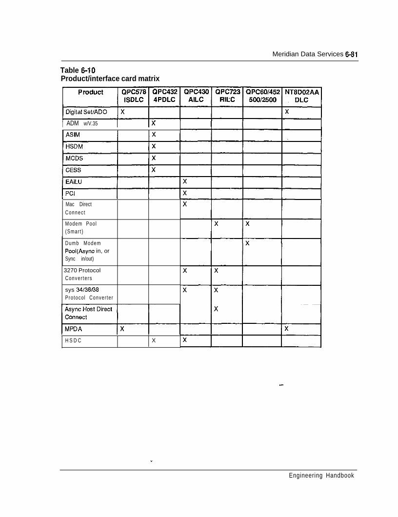
Meridian Data Services 6-81
Table 6-10Product/interface card matrix
1 ADM w/V.35 1 Ix
Mac DirectConnec t
Modem Poo l(Smar t )
Dumb ModemPool(Async in, orSync in/out)
~ 3270 ProtocolConver te rs
sys 3436t38Pro toco l Conver te r
H S D C X
_-
Engineering Handbook

7-1
Chapter 7 - System cotifigurationContentsIntroduction 1Autoquote 1Configuration guidelines 2Meridian 1 system options hardware provisioning 13
Universal Equipment Modules 13Power and cooling equipment 1 9Common Equipment cards 28Peripheral Equipment cards 35Station equipment 43
Software provisioning 46
IntroductionSystem configuration of the Meridian 1 SL-1 system options involves determiningthe hardware and software necessary to meet the specific requirements of theinstallation. This determination is based upon parameters related to quantity andtype of terminals, telephones, traffic, features, and services. An assessment of theserequirements indicates which particular member of the Meridian 1 system family isbest suited to address those particular needs.
AutoquoteThe Autoquote mechanism readily provides a system configuration based uponspecific input data pertaining to the required parameters. In addition to providing alisting of hardware and software and their associated ordering codes, reports mayalso be generated to denote traffic, memory, and real time estimations. Engineeringrules determine equipment provisioning and the capability exists to specifyrequirements on an “equipped” and “wired for” basis to address future growthprojections. Other services available include the capability to:- quote all available software generics and associated optional feature groups- quote all standard hardware items - -- indicate which hardware and software items are on a controlled release basis- configure systems to support non-blocking and RPE applications- generate configurations for different options using the same input data
requirements- save and later retrieve input data from one run and modify it for a subsequent
run- specify the spare capacity available in terms of memory, real time, traffic, and
hardware. ~,
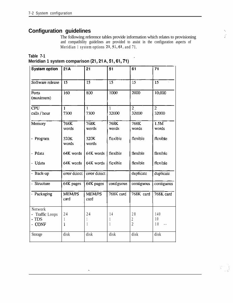
7-2 System configuration
Configuration guidelinesThe following reference tables provide information which relates to provisioningand compatibility guidelines are provided to assist in the configuration aspects ofMeridian 1 system options 21,51,61, and 71.
Table 7-1-Meridian 1 system comparison (21,21 A, 51,61,71)
Network- Traffic Loops 2 4 2 4 1 4 2 8 1 4 0- TDS 1 1 1 2 1 0- CONF 1 1 1 2 1 0 - -
Storage disk disk disk disk disk
‘\
I
;
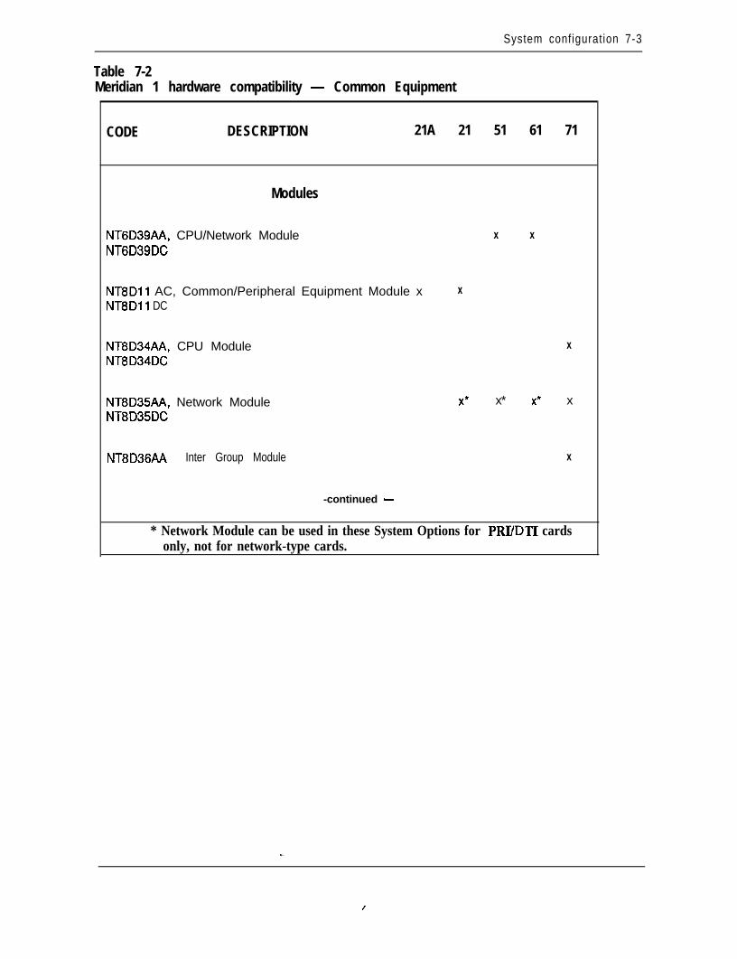
System configuration 7-3
Table 7-2Meridian 1 hardware compatibility - Common Equipment
CODE DESCRIPTION 21A 21 51 61 71
Modules
NT6D39AA, CPU/Network ModuleNT6D39DC
X X
NT8Dll AC, Common/Peripheral Equipment Module x X
NT8Dli DC
NT8D34AA, CPU ModuleNT8D34DC
X
NT8D35AA, Network ModuleNT8D35DC
x* x* x* x
NT8D36AA Inter Group Module X
-continued -
* Network Module can be used in these System Options for PRIIDTI cardsonly, not for network-type cards.
I
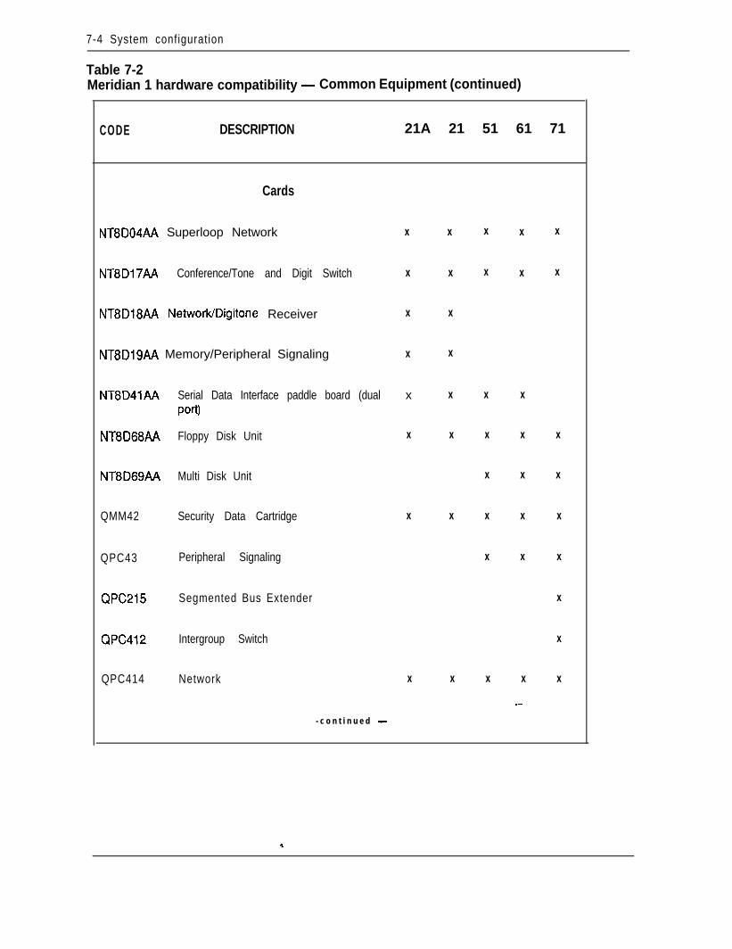
7-4 System configuration
Table 7-2Meridian 1 hardware compatibility - Common Equipment (continued)
CODE DESCRIPTION 21A 21 51 61 71
Cards
NT8D04AA Superloop Network X X X X X
NT8D17AA Conference/Tone and Digit Switch X X X X X
NT8D18AA NetworkIDigitone Receiver X X
NT8D19AA Memory/Peripheral Signaling X X
NT8D41AA Serial Data Interface paddle board (dual x X X X
Port)
NT8D68A.A Floppy Disk Unit X X X X X
NT8D69AA Multi Disk Unit X X X
QMM42 Security Data Cartridge X X X X X
QPC43 Peripheral Signaling X X X
QPC215 Segmented Bus Extender X
QPC412 Intergroup Switch X
QPC414 Network X X X X X
_-
- c o n t i n u e d -
*.
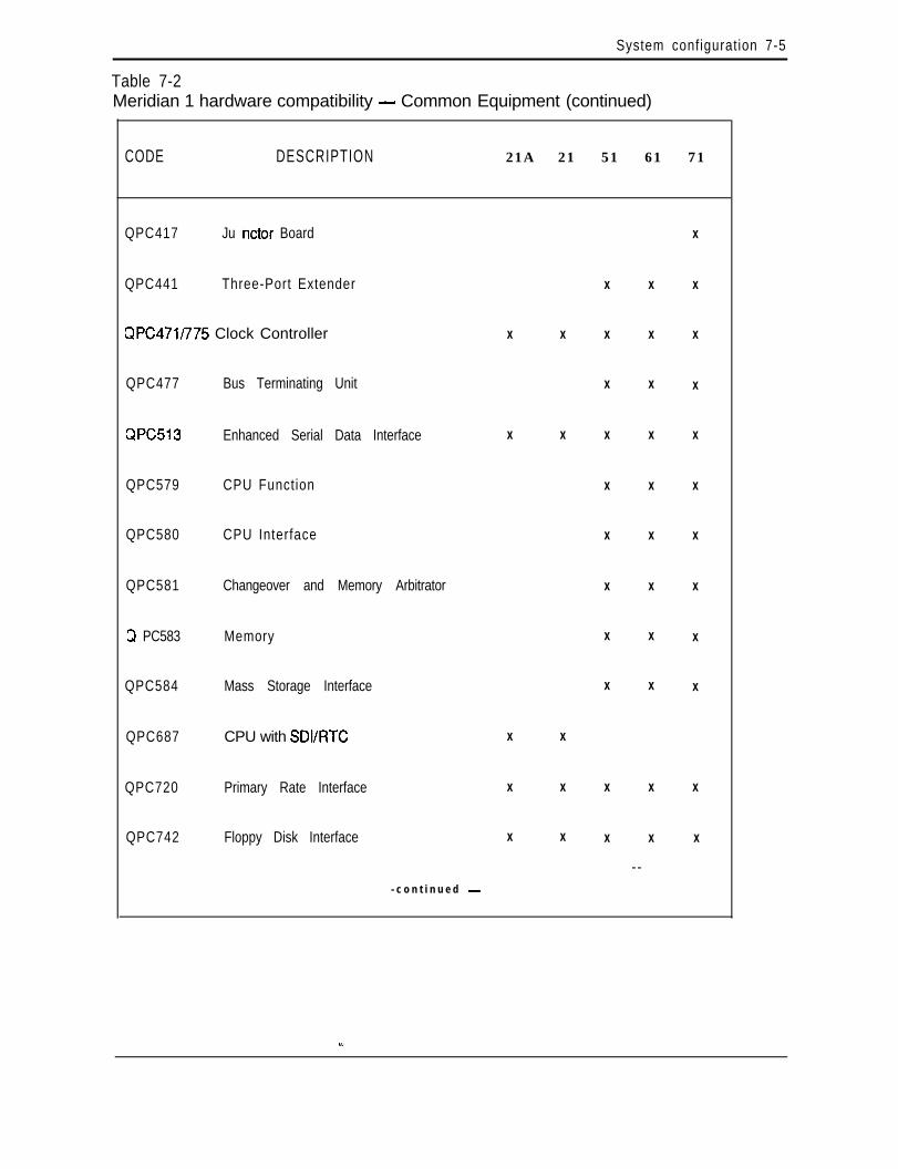
System configuration 7-5
Table 7-2Meridian 1 hardware compatibility - Common Equipment (continued)
CODE DESCRIPTION 21A 21 51 61 71
QPC417 Ju nctor Board X
QPC441 Three-Port Extender X X X
QPC471/775 Clock Controller X X X X X
QPC477 Bus Terminating Unit X X X
QPC513 Enhanced Serial Data Interface X X X X X
QPC579 CPU Function X X X
QPC580 CPU Interface X X X
QPC581 Changeover and Memory Arbitrator X X X
Q PC583 Memory X X X
QPC584 Mass Storage Interface X X X
QPC687 CPU with SDVRTC X X
QPC720 Primary Rate Interface X X X X X
QPC742 Floppy Disk Interface X X X X X
- -- c o n t i n u e d -
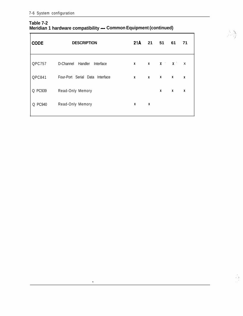
7-6 System configuration
Table 7-2Meridian 1 hardware compatibility - Common Equipment (continued)
DESCRIPTION 21A 21 51 61 71
QPC757 D-Channel Handler Interface X X X’ X’ x
QPC841 Four-Port Serial Data Interface X X X X X
Q PC939 Read-Only Memory X X X
Q PC940 Read-Only Memory X X
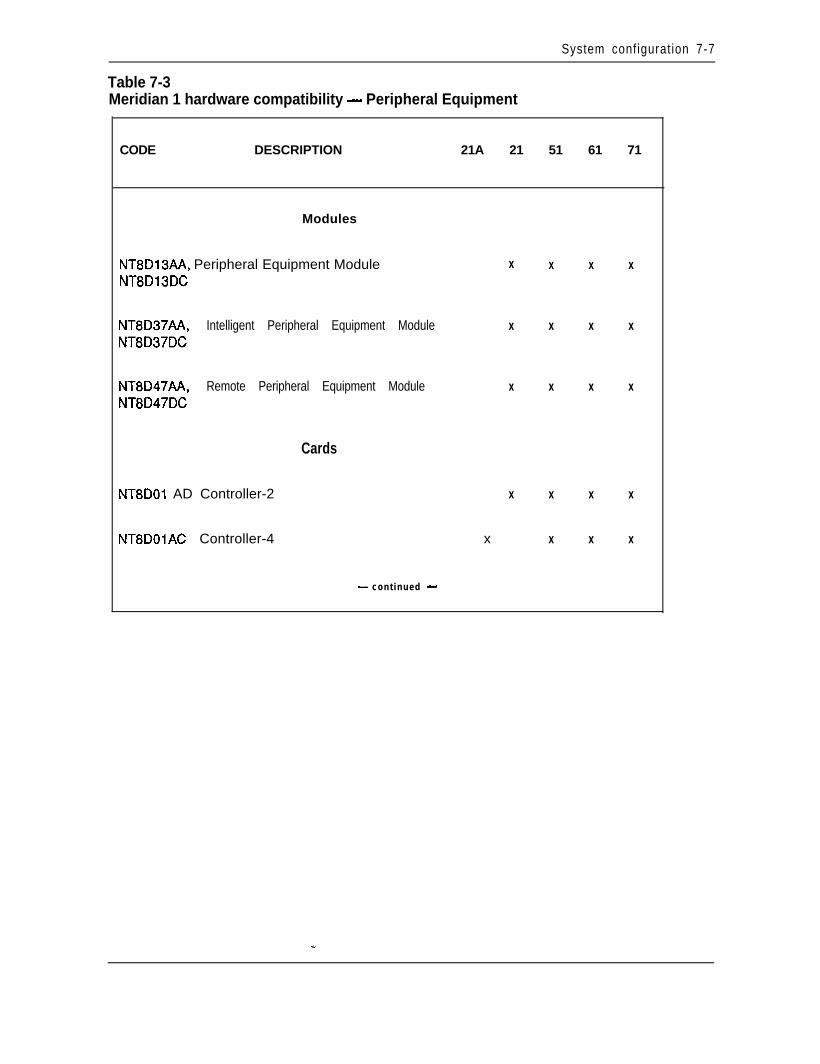
System configuration 7-7
Table 7-3Meridian 1 hardware compatibility - Peripheral Equipment
CODE DESCRIPTION 21A 21 51 61 71
Modules
NT8D13AA, Peripheral Equipment ModuleNT8D13DC
X X X X
NT8D37AA, Intelligent Peripheral Equipment Module X X X X
NT8D37DC
NT8D47AA, Remote Peripheral Equipment Module X X X X
NT8D47DC
Cards
NT8DOl AD Controller-2
NT8DOlAC Controller-4
X X X X
x X X X
- cont inued -
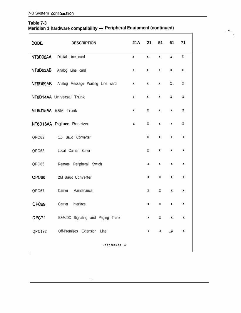
7-8 Svstem confiauration
Table 7-3Meridian 1 hardware compatibility - Peripheral Equipment (continued)
ZODE DESCRIPTION 21A 21 51 61 71
VT8D02AA Digital Line card X X - X X X
VT8D03AB Analog Line card X X X X X
NT8DOSAB Analog Message Waiting Line card X X X x_ x
NT8D14AA Universal Trunk X X X X X
NT8D15AA E&M Trunk X X X X X
NT8D16AA Digitone Receiver X X X X X
QPC62 1.5 Baud Converter X X X X
QPC63 Local Carrier Buffer X X X X
QPC65 Remote Peripheral Switch X X X X
QPC66 2M Baud Converter X X X X
QPC67 Carrier Maintenance X X X X
QPC99 Carrier Interface X X X X
QPC71 E&M/DX Signaling and Paging Trunk X X X X
QPC192 Off-Premises Extension Line X X X X_-
- c o n t i n u e d -
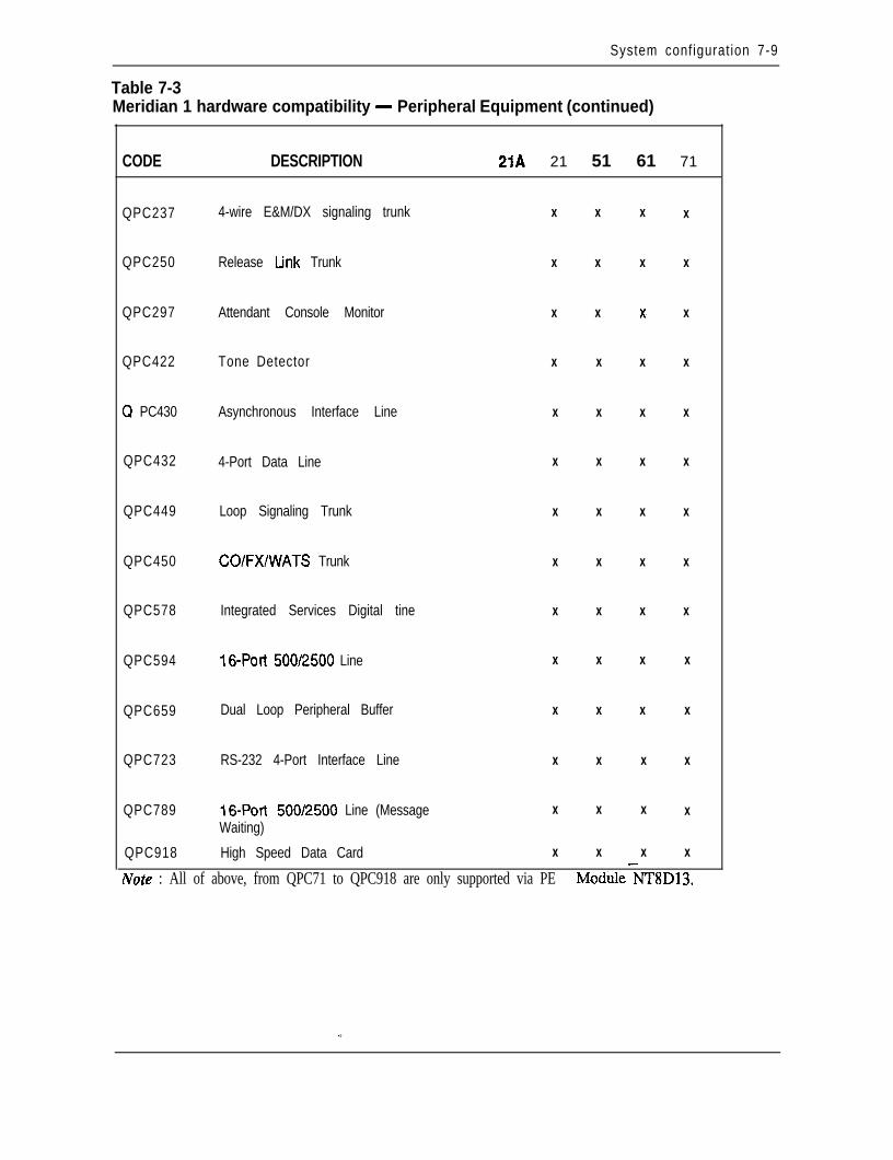
System configuration 7-9
Table 7-3Meridian 1 hardware compatibility - Peripheral Equipment (continued)
CODE DESCRIPTION 21A 21 51 61 71
QPC237 4-wire E&M/DX signaling trunk
QPC250 Release tink Trunk
QPC297 Attendant Console Monitor
QPC422 Tone Detector
Q PC430 Asynchronous Interface Line
QPC432 4-Port Data Line
QPC449 Loop Signaling Trunk
QPC450 CO/FX/WATS Trunk
QPC578 Integrated Services Digital tine
QPC594 16-Port 500/2500 Line
QPC659 Dual Loop Peripheral Buffer
QPC723 RS-232 4-Port Interface Line
QPC789
QPC918
16-Port 500/2500 Line (MessageWaiting)
High Speed Data Card
X
X
X
X
X
X
X
X
X
X
X
X
X
X
X
X
X
X
X
X
X
X
X
X
X
X
X
X
X
X
X-
X
X
X
X
X
X
X
X
X
X
X
X
X
X
X
X
X
X
X
X
X
X
X
X
X-Note : All of above, from QPC71 to QPC918 are only supported via PE Module NT8D13.
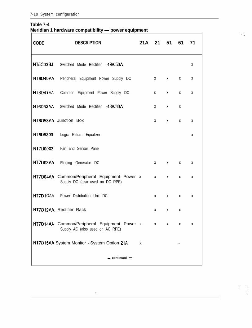
7-10 System configuration
Table 7-4Meridian 1 hardware compatibility - power equipment
CODE DESCRIPTION 21A 21 51 61 71
NT5C03BJ Switched Mode Rectifier -48V/50A X
NT6D40AA Peripheral Equipment Power Supply DC X X X X
NT6D41 AA Common Equipment Power Supply DC X X X X
NT6D52AA Switched Mode Rectifier -48V/30A X X X
NT6D53AA Junction Box X X X X
NT6D5303 Logic Return Equalizer X
NT7D0003 Fan and Sensor Panel
NT7D03AA Ringing Generator DC X X X X
NT7D04AA Common/Peripheral Equipment Power x X X X X
Supply DC (also used on DC RPE)
NT7Dl OAA Power Distribution Unit DC X X X X
NT7D12AA. Rectifier Rack X X X
NT7D14AA Common/Peripheral Equipment Power x X X X X
Supply AC (also used on AC RPE)
NT7D15AA System Monitor - System Option 21A
- continued -
x --
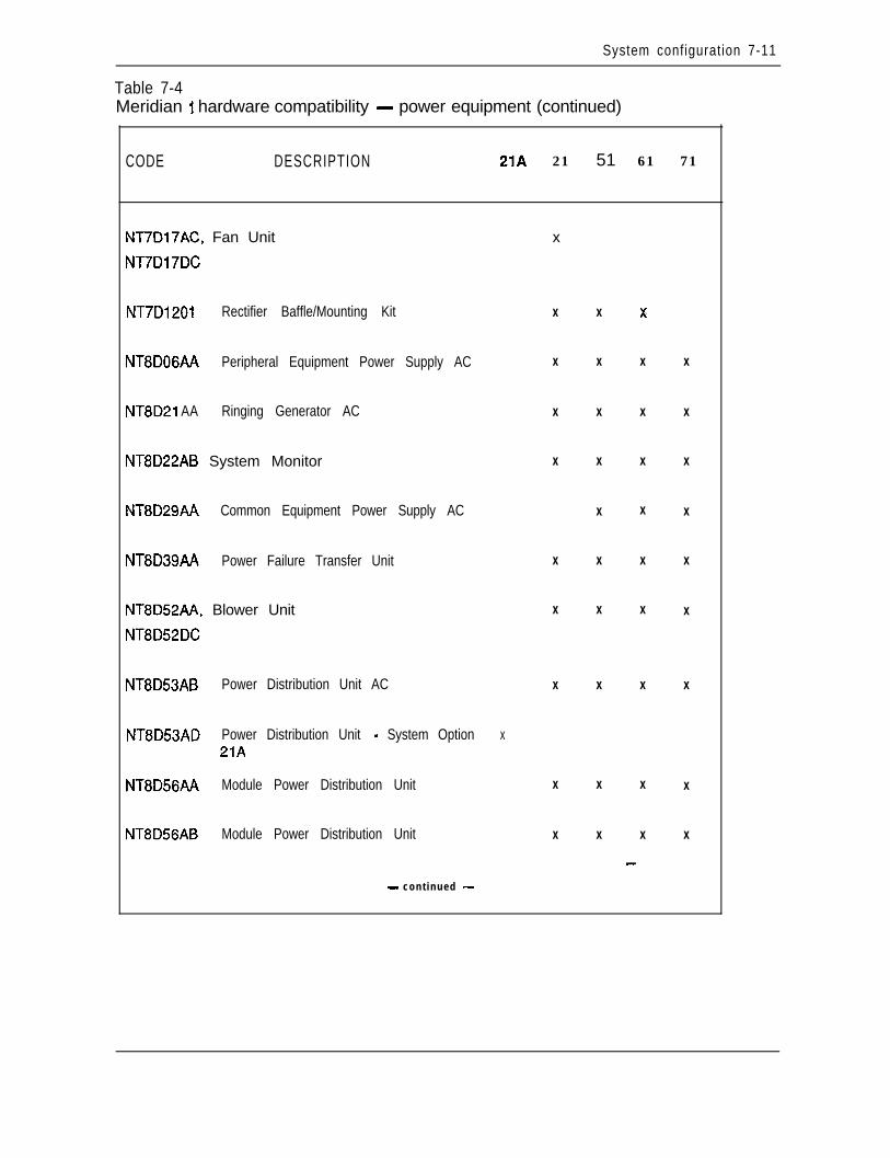
System configuration 7-11
Table 7-4Meridian 1 hardware compatibility - power equipment (continued)
CODE DESCRIPTION 21A 21 51 61 71
NT7D17AC, Fan Unit
NT7D17DC
x
NT7D1201 Rectifier Baffle/Mounting Kit
NT8DOGAA Peripheral Equipment Power Supply AC
NT8D21 AA Ringing Generator AC
NT8D22AB System Monitor
NT8D29AA Common Equipment Power Supply AC
NT8D39AA Power Failure Transfer Unit
NT8D52AA, Blower Unit
NT8D52DC
X X x
X X X X
X X X X
X X X X
X X X
X X X X
X X X X
NT8D53AB Power Distribution Unit AC X X X X
NT8D53AD Power Distribution Unit - System Option x21A
NT8D56AA Module Power Distribution Unit X X X X
NT8D56AB Module Power Distribution Unit X X X X
_-
- cont inued -
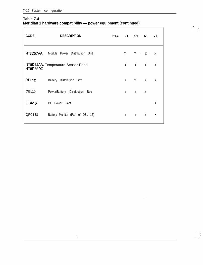
7-12 System configuration
Table 7-4Meridian 1 hardware compatibility - power equipment (continued)
CODE DESCRIPTION 21A 21 51 61 71
NT8D57AA Module Power Distribution Unit
NT8D62AA, Temperature Sensor PanelNT8D62DC
X x. X’ x
X X X X
QBL12 Battery Distribution Box X X X X
QBL15 Power/Battery Distribution Box X X X
WA13 DC Power Plant X
QPC188 Battery Monitor (Part of QBL 15) X X X X
System configuration 7-13
Meridian 1 system options hardware provisioningFollowing is a description of all hardware equipment of the Meridian 1 systemoptions 2 1,5 1,6 1,71 that can be ordered individually. The items are described interms of purpose, quantity required, and system hardware (system option), asappropriate.
Universal Equipment Modules
NT6D39AA, NT6D39DC CPU/Network Module
System hardware-System option 51/61
Purpos-The NT6D39 CPU/Network Module (hereafter referred to as NT6D39CPU/NET) houses a Central Processor Unit (CPU) and network cards.
This module is available in two versions:- NT6D39AA for AC systems- NT6D39DC for DC systems
The NT6D39 CPU/NET card cage contains 18 card slots which support thefollowing cards and functions:- network cards- Clock Controller- Serial Data Interface (SDI)/Enhanced Serial Data Interface (ESDI)- Peripheral Signaling- 3-Port Extender (3PE)- mass storage unit- CPU Function- CPU Interface- Changeover Memory Arbitrator (CMA)- Memory- D-Channel Handler Interface (DCHI)- Primary Rate Interface (PRI)/Digital Trunk Interface (DTI)
The NT6D39 CPU/NET Module is powered by a Common Equipment PowerSUPPlY. -Quantity-One per system option 5 1 ; two per system option 6 1
7-14 System configuration
NT6D44AA, NT6D44DC Meridian Mail ModuleSystem hardware--System option 21/51/51/71
Purpose-The NT6D44 Meridian Mail Module is a self-contained unit, complete .;with power converters and cooling units. It is designed to integrate with Meridian 1Communication Systems but is also available as a stand-alone system.
This module is available in two versions:- NT6D44AA for AC systems- NT6D44DC for DC systems
The Meridian Mail Module is powered by two Common Equipment PowerSupplies.
Refer to the Meridian Mail suite of documents (553-7041-xxx) for detailedinformation.
Quantity-Maximum of five per system
NT8Dll AC, NT8Dll DC Common/Peripheral Equipment ModuleSystem hardwaresystem option 21 and 21A
Purpose-The NT8Dll Common/Peripheral Equipment Module (hereafter referredto as NT8Dll CE/PE) supports CPU, network, and Intelligent PeripheralEquipment (IPE) cards in a single module.
This module is available in two versions:- NT8DllAC for AC systems- NT8DllDC for DC systems
The NT8Dll CE/PE card cage contains 20 card slots which support thefollowingcards and functions:- Floppy Disk Interface (FDI)/Floppy Disk Unit (FDU)- CPU- Memory- SDI/ESDI- network- network/Digitone Receiver (DTR)- DCHI- DTI/PRI- IF’E
System configuration 7-15
The NT8Dll CE/PE Module is powered by a Common/Peripheral Equipment(CE/PE) Power Supply.
Quantity-One per system
NT8D13AA, NT8D13DC Peripheral Equipment ModuleSystem hardware--System option 21/51/61/71
PurposcThe NT8Dl3 Peripheral Equipment Module (hereafter referred to asNT8D13 PE) supports the Dual Loop Buffer (DLB), and 10 card slotsThe PEBuffer is situated near the center of the module, with five cards to the left and fivecards to the right.
This module is available in two versions:- NT8D13AA for AC systems- NT8D13DC for DC systems
The NT8D13 PE Module is powered by a Peripheral Equipment Power Supply, anda Ringing GeneTator when 500/2500 sets are supported by the module.
Quantity-As required; refer to System engineering (553-3001-151)
NT8D34AA, NT8D34DC CPU ModuleSystem hardware-System option 71
Purpos+The NT8D34 CPU Module (hereafter referred to as NT8D34 CPU)houses the CPU, memory cards, and the mass storage.
This module is available in two versions:- NT8D34AA for AC systems- NT8D34DC for DC systems
The NT8D34 CPU card cage contains 15 card slots which support the followingcards and functions:- Memory- CMA- CPU Interface- CPU Function- SDI/ESDI- MS1- Segmented Bus Extender (SBE)- DCHI- PRI/DTI- Clock Controller- Mass Storage Unit (MSU) or Floppy Disk Unit (FDU)
7-16 System conficwration
The NT8D34 CPU Module is powered by a Common Equipment Power Supply.
Quantity-Two per system
NT8D35AA, NT8D35DC Network ModuleSystem hardwardystem option 71
PurposcThe NT8D35 Network Module (hereafter referred to as NT8D35NET)provides the signal interface between the Common Equipment (CE) cardslocated in the module.
This module is available in two versions:- NT8D35AA for AC systems- NT8D35DC for DC systems
The NT8D35 NET card cage contains 15 card slots which support the followingcards and functions:- 3PE- Intergroup Switch (IGS) (for system option 71 only)- peripheral signaling- network cards- SDI/ESDI- PRI/DTI
The NT8D35 NET Module is powered by a Common Equipment Power Supply.
-h
>,’
Quantity-A maximum of 10 per system (five network groups), excludingadditional requirements for PRI/DTI.
NT8D36AA Inter Group ModuleSystem hardwar+System option 71
PurposcThe NT8D36AA Inter Group Module provides a path for the switchingof traffic between the network groups in the system. Faceplate cables from theClock Controller (CC) and Intergroup Switch (IGS) circuit cards are connected tothe Inter Group Module. This module uses a QPC417 Junctor Board.
This module is used in both AC and DC systems.
Quantity-One per system _-
NT8D37AA, NT8D37DC Intelligent Peripheral Equipment ModuleSystem hardwardystem option 21/5 l/6 l/7 1
Purpose-The NT8D37 Intelligent Peripheral Equipment Module (hereafterreferred to as NT8D37 IPE) supports a Controller card and 16 IPE cards. TheController card is situated near the center of the module, between slot 7 and slot 8.
This module is available in two versions: ?*. ;
System configuration 7-17
- NT8D37AA for AC systems- NT8D37DC for DC systems
The card slots in the NT8D37 IPE card cage support the following cards:- Universal Trunk- E&MTrunk- Digitone Receiver (DTR)- Analog Line card (ALC)- Digital Line card (DLC)- Analog Message Waiting Line card (MLC)
The NT8D37 IPE Module is powered by a Peripheral Equipment Power Supply,and a Ringing Generator when 500/2500 sets are supported by the module.
Quantity-As required; refer to System engineering (553-3001-151)
NT8D47AA, NT8D47DC Remote Peripheral Equipment ModuleSystem hardwartiystem option 21/51/61/71
Purpose--The NT8D47 Remote Peripheral Equipment Module (hereafter referredto as NT8D47 RPE) is an interface module used to extend the interconnectiondistance between local and remote sites.
The same module is used for both local and remote applications. On the local side,it interfaces to the QPC414 Network card for up to two network loops; on theremote side, it supports the NT8D13 PE Module.
This module is available in two versions:- NT8D47AA for AC systems- NT8D47DC for DC systems
The NT8D47 RPE card cage contains 12 card slots which support the followingcards and functions:- 1.5 Mb converter- 2 Mb converter- carrier interface- remote peripheral- local carrier buffer- carrier interface- 2 Mb converter- 1.5 Mb converter- carrier maintenance- PRI/DTI (optional)
7-18 System configuration
The NT8D47 RPE Module is powered by a Common Equipment/PeripheralEquipment Power Supply.
Quantity-Since each NT8D47 RPE Module serves two network loops, thenumber of modules required per system depends on the number of stations in theremote site.
PackagingNT8D49 Spacer KitSystem Hardware-All
PurposeBolts modules together for side-by-side expansion. The Spacer ,%tincludes:- expansion spacer- RF gasketing- eight bushings
NT8D55AA Universal Equipment Module coverSystem Hardware-All
Purpose--This is the front or rear cover that is part of the UEM. Two covers arerequired for each UEM.
Universal Equipment Module side panelSystem Hardware-All
PurposcThis is the side panel (PO699724) that is part of the UEM. A maximumof eight panels are required for multi-column systems.
Card cage assembliesA card cage assembly consists of a sheet metal case and an associated backplane.The card cage provides the physical framework that houses the circuitry and powersupplies within the UEM.
The following is a list of all the card cage assemblies available and theircorresponding UEMs:- NT6D3903 NT6D39AA/DC CPU/Network Module- NT8D1103 NTSD 11 AC/DC Common/Peripheral Equipment
Module- NT8Dl303- NT8D3403- NT8D3503- NT8D3703
NT8D13AA/DC Peripheral Equipment-Module’NT8D34AA/DC CPU Module
NT8D35AA/DC Network ModuleNT8D37AA/DC Intelligent Peripheral EquipmentModule
- NT8D4703 NT8D47AA/DC Remote Peripheral EquipmentModule
System confiauration 7-19
Top CapSystem Hardware-AU
Purpos-The top cap is mounted on the highest module of each column. The topcap is approximately 80 cm (31.5 in.) wide by 55.9 cm (22 in.) deep by 7.6 cm (3in.) high and weighs 3.6 kg (8 lbs). It consists of a front and a rear air exhaust grilland thermal sensors. System option 21A contains a small fan to cool the powersuPPlY.
Three versions of the top cap are available:- NT7DOOAA AC systems- NT7DOOBA DC systems- NT7DOOAC system option 21A only
PedestalSystem Hardware-All
Purpose-The Pedestal is a base unit made of die-cast construction. It isapproximately 80 cm (3 1.5 in.) wide by 64.8 cm (25.5 in.) deep by 25.4 cm (10 in.)high and weighs 13.6 kg (30 lbs) empty. Leveling feet are provided for up to fourtiers, while a caster option is provided for up to two tiers.
The pedestal is available in three versions:- NT8D27AB for AC systems- NT8D27AC for system option 21A only- NT7D09AA for DC systems
The pedestal for AC and DC systems (except system option 21A) can house any ofthe following field replaceable assemblies:- Power Distribution Unit NT8D53AB or NT7DlOAA- Blower Unit NT8D52AA or NT8D52DC- Fan Unit NT7D17AC or NT7D17DC- Leveling foot A0318207- Air grill (molded) PO699797- Air filter PO699798
The pedestal for system option 21A is basically the same as the one used for othersystem options except it can only house the following field-replaceable assemblies:- Power Distribution Unit NT8D53AD- Leveling foot A03 18207- Air grill (molded) PO699797
7-20 System configuration
Power and cooling equipmentA0367754TopCapFanSystem Hardware-System option 2 1 A ,’PurposcThe A0367754 Top Cap Fan is located in the Fan and Sensor Panel. Itprovides cooling for the NT7D14AA CE/PE power Supply AC. There is no speedor temperature control provided with it. Power to the Top Cap Fan is controlled bythe circuit breaker located on the back panel of the pedestal.
Quantity-One per system
NT5C03BJ Switched Mode Rectifier -48V150ASystem Hardware-System option 7 1 (DC version)
Purpose-Solid state, switched-mode rectifier. Converts 208/240 VAC (nominal)to -48 VDC (nominal), with a 50A output. Used in the QCA13 power plant, withup to ten rectifiers in parallel.
Quantity-As required by system power consumption
NT6D40AA Peripheral Equipment Power Supply DCSystem Hardware-All
Purpose-The Peripheral Equipment Power Supply DC is used to provide power toall peripheral equipment modules in DC systems. It converts -48V DC to +5V,+8.5V, +lOV, _+15V, and -48V DC voltages used to power peripheral equipmentlogic cards and to supply talk battery to lines and trunks. This power supply islocated in the far left hand card slot labeled “PE Pwr Sup”.
Quantity-One Peripheral Equipment Power Supply DC is used in each of thefollowing DC modules:- Intelligent Peripheral Equipment Module (NT8D37DC)- Peripheral Equipment Module (NT8D13DC)
NT6D41 AA Common Equipment Power Supply DCSystem Hardware-All
Purpose-The Common Equipment Power Supply DC is used in the commonequipment modules in DC systems. It is located in the first slot on the left in themodule labeled “CE Pwr Sup”. It converts -48V DC to +5V and +12 V DC toprovide all required voltages for CE and network circuit cards
Quantity-One Common Equipment Power Supply DC is used in each of thefollowing DC modules:- CPU Module (NT8D34DC)- Network Module (NT8D35DC)- CPU/Network Module (NT6D39DC)
System configuration 7-21
Two Common Equipment Power Supply DC units are used in the Meridian MailModule (NT6D44DC).
NT6D52AA Switched Mode Rectifier -48V/30ASystem Hardware-System option 21/51/61 (DC versions)
PurposeThe Switched-Mode Rectifier is based on the QRF12 rectifier, withshielding to limit electromagnetic interference. It converts 208/240 VAC (nominal)to -48 VDC (nominal), with a 30A output. It connects to the system through theQBLl5 Battery Distribution Box.
Quantity-Generally one rectifier per every three modules. Exact quantitydepends on system configuration and power requirements. _
NT6D53AA Junction BoxSystem Hardware-All (DC version)
Purpose-The Junction Box is required when the distance from the rectifier to thepedestal is over 0.74 m (8 ft), which requires wire larger than 10 AWG. It providesa set of connection terminals for the 4-AWG wire that comes from the rectifier, anda set of connection terminals for the lo-AWG wire that goes into the pedestal.
Refer to Power engineering (553-3001-152) for more information.
Quantity-One per DC pedestal
NT6D5303 Logic Return EqualizerSystem Hardware-System option 7 1 (DC version)
Purpose--The Logic Return Equalizer (LRE) mounts on top of the QCA13 cabinet.It is used as the single point ground for system option 71.
Quantity-One per system
NT/D0003 Fan and Sensor PanelSystem Hardware-System option 2 1 A
PurposeThe NT7D0003 Fan and Sensor Panel contains a 230 VAC tubeaxialfan (A0367754) and a thermal sensor for a high temperature/shutdown alarm to theOption 21A System Monitor. The fan provides cooling for the NT7D14AACommon/Peripheral Equipment Power Supply. It is on continously and receivespower directly from the Power distribution Unit via the module power harness.
The NT7D0003 Fan and Sensor Panel consists of the following:- a perforated top shield (PO703062)- a Top Cap Fan (A0367754)- a fan power harness (NT7D0004)- a thermostat harness (NT8D46AC)

7-22 System configuration
Quantity-One per system
NT7D03AA Ringing Generator DCSystem Hardware-All DC system options
Purpose-The Ringing Generator DC operates from a nominal -48V DC input andprovides selectable AC ringing voltage outputs superimposed on -48 VDC. Thefrequency and voltage options are 20/25/50_Hz and 70/80/86 VAC. It also supplies-15OV DC Message Waiting lamp 500/2500 set applications. The RingingGenerator DC mounts in the PE modules to the right of the Peripheral EquipmentPower Supply DC.
Quantity-One Ringing Generator DC is used in each of the following, when theseDC modules support 500- or 2500-type analog sets:- Intelligent Peripheral Equipment Module (NT8D37DC)- Peripheral Equipment Module (NT8Dl3DC)
Nl7DO4AA Common/Peripheral Equipment Power Supply DCSystem Hardware-All (DC options)
Purpose---The Common/Peripheral Equipment Power Supply DC converts -48VDC to +5V, +8.5V, +ISV, _+12V, -48V, and -150V DC voltages used to powerperipheral and common equipment, supply talk battery, and light Message Waitinglamps on 500/2500 sets. It provides selectable AC ringing voltage outputssuperimposed on -48 VDC. The frequency and voltage options are 20/25/50 Hz and70/80/86 VAC. It is located to the left of the module, in the slot labeled “CE/PEPwr Sup”.
Quantity-One Common/Peripheral Equipment Power Supply DC is used in eachof the following DC Modules:- Common/Peripheral Equipment Module (NT8DllDC )- Remote Peripheral Equipment Module (NTSD47DC)
Nl7DlOAA Power Distribution Unit DCSystem Hardware-All except system option 2 1 A
Purpose--The NT7DlOAA Power Distribution Unit DC distributes power to theentire column. It is located in the rear of the pedestal. It houses five circuitbreakers (one for each Module and one for the Blower Unit) and the SystemMonitor.
Quantity-One per pedestal/column in DC systems - -
Nl7D12AA Rectifier RackSystem Hardware-21/5 l/61 (DC versions)
Purpose--This is a 48.3-cm (19-in.) open relay rack which is approximately 1.5 m(5 ft) high. It supports up to three NT6D52AA Rectifiers in a single column.
:*. ..:
System configuration 7-23
Quantity-One rack per every three NT6D52AA Rectifiers, up to a maximum ofthree racks per system
Nl7D14AA Common/Peripheral Equipment Power Supply ACSystem Hardware-System Options 21/21A And all RPE
Purpose-The Common/Peripheral Equipment Power Supply AC converts208/24OV AC to +5V, +8SV, +I%, _+12V; -48V, and -lS.OV DC voltages used topower peripheral and common equipment, supply talk battery, and light MessageWaiting lamps on 500/2500 sets. It provides selectable AC ringing voltage outputssuperimposed on -48 VDC. The frequency and voltage options are 20/25/50 Hz and70/80/86 VAC. It is located in the left of the module, in the slot labeled “CE/PEPwr Sup”.
Quantity-One Common/Peripheral Equipment Power Supply AC is used in eachof the following AC modules:- Common/Peripheral Equipment Module (NTSDl 1AC)- Remote Peripheral Equipment Module tm8D47AA)
NT7D15AA System Monitor - System Option 21 ASystem Hardware-System option 21A
Purpose-The NT7D15AA System Monitor - System Option 21A provides aninterface to communicate and monitor the NT7D14AA CE/PE Power Supply AC,the CPU, and the thermal switches. In the event of failure, the System Monitor-System Option 21A is notified and the appropriate alarm is set. A system alarmLED located below the top cap lights to indicate CPU failure.
Quantity-One per system
NT7D17AC Fan Unit ACSystem Hardware-System option 21 with up to two tiers
Purpose-The NT7D17AC Fan Unit AC is housed within the pedestal andprovides cooling for the entire column. It consists of three fans and a circuit breakerlocated in the front.
Quantity-One per pedestal
Nl7D17DC Fan Unit DCSystem Hardware--System option 21 with up to two tiers _ _
Purposc+The NT7D17DC Fan Unit DC is the same as the NT7D17AC Fan UnitAC except that it is used for DC systems. It has an on/off switch in the front and itsown separate circuit breaker located on the Power Distribution Unit.
Quantity-One per pedestal
,NT/D1201 Rectifier Baffle/Mounting KitSystem Hardwfre-System option 21/51/61 (DC versions)

7-24 System configuration
Purpos-The Rectifier Baffle/Mounting Kit consists of a set of support bracketsfor mounting the NT6D52AA Rectifier to an NT7D12AA Rack, and a heat baffleplate. The baffle directs exhaust air from the lower rectifier away from the inlet tothe upper rectifier, thereby allowing cooling by natural convection .
\-‘,
1’
Quantity-One per NT6D52AA Rectifier
NT8DOGAA Peripheral Equipment Po_wer Supply ACSystem Hardware-All except system option 21A
PurposcThe Peripheral Equipment Power Supply AC is used to provide power toall peripheral equipment modules in AC systems. It converts 208/24OV AC to +5V,+8.5V, +lOV, _+15V, and -48V DC voltages used to power peripheral equipmentlogic cards and to supply talk battery to lines and trunks. This power supply islocated in the far left-hand card slot labeled “PE Pwr Sup”.
Quantity-One Peripheral Equipment Power Supply AC is used in each of thefollowing AC modules:- Intelligent Peripheral Equipment Module (NT8D37AA)- Peripheral Equipment Module (NT8D13AA)
NT8D21 AA Ringing Generator ACSystem Hardware-All except system option 21A
Purpose-The Ringing Generator AC operates from a nominal 208/240 VAC inputand provides selectable AC ringing voltage outputs superimposed on -48 VDC. Thefrequency and voltage options are 20/25/50 Hz and 70/80/86 VAC. It also supplies-150V DC Message Waiting lamp 500/2500 set applications. The RingingGenerator AC mounts in the PE modules to the right of the Peripheral EquipmentPower Supply.
Quantity-One Ringing Generator AC is used in each of the following, when theseAC Modules support 500- or 2500-type analog sets:- Intelligent Peripheral Equipment Module (NT8D37AA)- Peripheral Equipment Module (NT8D13AA)
NT8D22AB System MonitorSystem Hardware-All except system option 2 1 A
Purpos+The NT8D22AB System Monitor monitors the status of all internalpower and cooling related components, as well as external DC rectifiers, batteries,and Uninterruptable Power Supplies (UPS). The System Monitor is mounted in thePower Distribution Unit, within the Pedestal.
The System Monitor that handles the communication with the system CPU (via SD1port) is the master; all others function as slaves. There is a serial communicationlink between the master and the slave System Monitors. In addition to CPU statusreporting, the System Monitor also controls all external visual status indications.
;:*.
System configuration 7-25
Quantity-One master and up to 63 slave System Monitors are allowed per system.
NT8D29AA Common Equipment Power Supply ACSystem Hardware-System option 5 l/61/71
Purpos+The Common Equipment Power Supply AC is used in the commonequipment modules in AC systems. It is located in the first slot on the left in themodule labeled “CE Pwr Sup”. It converts 208/24OV AC to +5V and +12 V DC toprovide all required voltages for CE and network circuit cards.
Quantity-One Common Equipment Power Supply AC is used in each of thefollowing AC Modules:- CPU Module (NT8D34AA)- Network Module (NT8D35AA)- CPU/Network Module (NT6D39AA)
Two Common Equipment Power Supply AC is used in the Meridian Mail Module(NT6D44AC).
A0355200 Power Failure Transfer UnitSystem Hardware-All except system option 21A
PurposcProvides an interface between CO lines, PBX, and 500/2500 phones(rotary dial and pushbutton). The Power Failure Transfer Unit allows eight phonesto be connected to the CO lines in the event of a PBX power failure or malfunction.The Power Fail Transfer Unit is transparent to the switch and CO lines duringnormal PBX operations.
The Power Failure Transfer Unit is approximately 22.8 cm (9 in) long by 22.8 cm (9in) wide by 8.8 cm (3.5 in) deep. It is screw-mounted to the Distribution Frame andconnects to the Main Distribution Frame and switch by two 25-pair cables.
Quantity-As required
NT8D52AA Blower UnitSystem Hardware-All except system option 21A
Purpose-The Blower Unit is part of the system cooling assembly and providesforced-convection cooling. Housed within the pedestal, it contains two backward-curved impellers (rotor blades) which are cylindrically shaped, approximately 22.8cm (9.in) in diameter, and 6.9 cm (2.75 in) thick. A circuit breaker is located on thefront of the blower chassis to turn the unit on and off. Each unit weighs about 1.5kg (3.5 lbs).
The unit communicates with the power distribution section by engaging a connectorin the rear of the pedestal.
Quantity-One per pedestal in AC systems
7-26 System configuration
NT8D52DC Blower UnitSystem Hardware-AU except system option 21 A
PurposcThis Blower Unit is the same as the NT8D52AA Blower Unit except thatit is used for DC systems. It has its own separate circuit breaker located on thePower Distribution Unit. Also, for maintainability in the field, a switch is locatedon the front of the blower chassis to turn the unit on and off.
Quantity-One per pedestal in DC systems
NT8D53AB Power Distribution Unit ACSystem Hardware-All except system option 21A
Purpos+The Power Distribution Unit AC distributes power to the entire column.It is located in the rear of the pedestal. It houses a main circuit breaker and theSystem Monitor.
Quantity-One per pedestal/column in AC systems
NT8D53AD Power Distribution Unit - System Option 21ASystem HardwarMystem option 21A
Purpos+-The Power Distribution Unit - System Option 21A is a panel located inthe pedestal. It contains a circuit breaker, a terminal block, and an EMI filter. Thepower cable enters the pedestal and connects to the circuit breaker. From the circuitbreaker, the AC voltage goes to the terminal block through the EM1 filter and backto the terminal block where it is distributed to the NT7D14AA CE/PE PowerSupply AC and the fan located in the top cap.
Quantity-One per system
NT8D56AA Module Power Distribution UnitSystem Hardware-All except system option 21A
PurposcThe NT8D56AA Module Power Distribution Unit protects the powersupply and distributes power within a module. It houses a single breaker and isused in conjunction with the NT8D29AA CE Power Supply AC.
Quantity-One per NT8D35AA NET, NT6D39AA CPU/NET, or N’lXD34AACPU Module
NT8D56AB Module Power Distribution Unit --System Hardware-All except system option 21A .
Purpose-The NT8D56AB Module Power Distribution Unit protects the powersupply and distributes power within a module. It houses a single breaker and isused in conjunction with the NT7D14AA CE/PE Power Supply AC.
Quantity-One per NT8D47AA RPE Module
System configuration 7-27
NT8D57AA Module Power Distribution UnitSystem Hardware--All except system option 21A
Purpose--The NT8D57AA Module Power Distribution Unit protects the powersupply and distributes power within a module. It houses a dual breaker and is usedin conjunction with the NT8D06AA PE Power Supply AC and the NT8D21AARinging Generator AC.
Quantity-One per NT8D13AA PE or NT8D37AA IPE Module
NT8D62AA, NT8D62DC Temperature Sensor PanelSystem Hardwar-All except system option 2 1A.
Purpose-The NT8D62 Temperature Sensor Panel communicates with the SystemMonitor in the event of overheating. It contains two temperature sensors whichprotect against thermal damage by detecting extreme temperature.
The Temperature Sensor Panel is available in two versions:- NT8D62AA for AC systems- NT8D62DC for DC systems
The Temperature Sensor Panel consists of the following:- a perforated shield panel (PO703062)- an LED bracket (PO703061)- a thermostat harness (NT8D46AC)- an air probe harness (NT8D46AM or NT8D46DC)- an air probe connector bracket (PO703064 or PO708 186)
Quantity-One per top cap
QBLlP Battery Distribution BoxSystem Hardware--All (DC versions)
Purpose-Connects customer-provided power supplies to the system. Allowsconnection of up to 24 modules. Provides connection points, fused outputs, and ’monitoring of rectifiers and batteries.
Quantity-One per system
QBL15 Power/Battery Distribution Box --System Hardware---System option 21/51/61 (DC versions)
Purpose-Allows the parallel connection of up to three NT6D52AA Rectifiers, forconnection to the system and to reserve batteries. Includes main fuses, diodeblocking, test points, QPC188 battery monitor card, and sense lead fusing onconnections from each rectifier.
7-28 System configuration
Quantity-One per every three NT6D52AA Rectifiers, up to a maximum of twoQBLlSs per system
QCA13 DC Power PlantSystem Hardware--System option 71 (DC version)
Purpose+Consists of a primary power cabinet with fusing and distributionhardware, monitoring and control, and up to four NT5CO3 50A Rectifiers. Up totwo supplemental cabinets can be added, with up to four rectifiers in the firstsupplemental cabinet and up to two rectifiers in the second cabinet, for a total of 10rectifiers and a total system capacity of 500A. (This power system is also referredto as the 52412 power plant;more commonly used name.)
QCA13 is actually the cabinet designation, but is the
Quantity-As required by system power consumption
QPC188 Battery MonitorSystem Hardware-All (DC versions)
Purpos-Located in each Battery Distribution Box to monitor rectifier and batteryvoltages. Generates low float alarm, low voltage trip alarm and sense lead fuseconditions.
Quantity-One circuit card in QBL12 or QBLl5
QRF12 -52 V RectifierSystem Hardware-System option 21/5 l/61 (DC version)
Purpos+Converts 115 V AC and 220 V AC to -52 V DC (nominal). QRF12Bvoltage conversions from 90V to 129V, and 190V to 250V. Connects to thecolumns through the QBLl5 Power/Battery Distribution Box.
Quantity-One for every two, or three modules, depending on load andredundancy requirements.
Common Equipment cardsNT8D04AA Superloop NetworkSystem Hardware-All
Purpose- Provides 120 time slots (one superloop) interface between Network andIntelligent Peripheral Equipment. Utilizes the equivalence of four network loops.May be connected to one or two NT8DOl Controller card(s).
- -The Superloop Network card is equipped with a Motorola 68000-typemicroprocessor which performs network diagnostics and signaling control, andcommunicates with the Intelligent Peripheral Controller.
Quantity-Up to four per Network Module as required. Refer to Systemengineering (553-3001-151) for engineering details.
System configuration 7-29
NT8D17AA Conference/Tone and Digit Switch (TDS)System Hardware-All
Purpose--Provides both Conference and TDS functions. This card accesses twonetwork loops, one for each function.
The Conference circuitry has a warning tone opiion and supports broadcast mode.Up to 15 simultaneous conferences can be controlled with the restriction that thetotal number of conferees in all conferences is not greater than 30.
The TDS circuitry provides tones for different countries (up to 256 tones andcadences).
Quantity-As required. Refer to system engineering (553-3001-151) forengineering details.
NT8D18AA NetworWDigitone ReceiverSystem Hardware-System option 2 1 and 2 1 A
PurposeCombines the functionality of the Network Controller and DigitoneReceiver cards in a mother/daughterboard assembly. The mother board plugs into adedicated slot on the backplane. The daughter board attaches to the mother boardthrough an SDI/ESDI connector and does not connect to the backplane.
Quantity-One per NT8Dll CE/PE Module
NT8DlSAA Memory/Peripheral SignalingSystem Hardware-System option 2 1 and 2 1 A
Purpost+Combines the functionality of the Memory and Peripheral Signalingcards, as well as miscellaneous CPU functions.
The CPU functions include interrupt and fault monitoring.
The Peripheral Signaling function provides:- signaling interface between CPU and Peripheral Equipment for up to 32
network loops- clock and timing signals for real-time transmission functions
Quantity-One per NT8Dll CE/PE Module
NT8D41 AA Serial Data Interface paddle board (dual-port)System Hardware-System option 2 1 A/2 l/5 l/6 1 ’
Purpose--Provides two serial ports between the SL-1 processor and an externaldevice. Each port supports- RS-232-C interface- 8-bit ASCII data with parity and stop bit- asynchronous, start-stop operation
.
7-30 System configuration
- data rates of 300,600,1200,2400,4800, and 9600 baud- Data Terminal Equipment (DTE) mode- Data Communication Equipment (DCE) mode
Quantity-Three maximum per NTSDll CE/PE Module; two maximum perNT6D39 CPU/NET Module
NT8D68AA Floppy Disk UnitSystem hardware-All
Purpose-The Floppy Disk Unit (FDU) is used to load the programs and officedata into the system memory. The FDU contains two 3.5inch floppy drives and iscontrolled by the QPC742 Floppy Disk Interface (FDI). Each floppy drive has aformatted capacity of 1.44 MB.
The FDU occupies two adjacent card slots in the CPU, Network, or PE Module. Itis powered through the cable connecting it to the FDI. The FDU can be connectedto one or two FDIs as required by the system.
Quantity-One per system
NT8D69AA Multi Disk UnitSystem hardware-System option 51/61/71
PurposcThe Multi Disk Unit (MDU) is used to load the programs and office datainto the system memory. The MDU contains the following:- two 3.5inch floppy1 drives which are connected to the SCSI interface through
the SCSI/floppy controller; each drive has a formatted capacity of 1.44 MB- a 3.5inch hard disk drive which has a built-in SCSI interface and a capacity of
20 MB- an SCSI/floppy controller
The MDU occupies three adjacent card slots in the CPU, CPU/NET, or NetworkModule and requires 5V and 12V from the module. The MDU is controlled by theQPC584 Mass Storage Interface (MSI). The MDU can be connected to one or twoMSIs as needed.
Quantity-One per system
QMM42 Security Data CartridgeSystem Hardware-AU _-
Purpose--This is a security measure that allows a customer access only to softwarepackages purchased for his system. This security data cartridge is mounted oneither the QPC584 Mass Storage Interface or QPC742 Floppy Disk Interface card.
Quantity-One per MSI/FDI card
System configuration 7-31
QPC43 Peripheral SignalingSystem Hardware-System option 5 l/6 l/7 1
Purpos+Provides a signaling interface between the CPU and PE via the Networkcards. Provides basic bit rate 2.048 MHz clock and timing signals for real-timefunctions.
Quantity-One per NT8D35 NET or NT6D39 CPU/NET Module
QPC215 Segmented Bus ExtenderSystem Hardware-System option 71
Purpose--The Segmented Bus Extender (SBE) extends CPU bus signals (address,data, and control) to the Network Module. It also allows recovery of calls byisolating bus faults to a single network group.
Note: QPC215C or later vintage is required.
Quantity-One circuit card in each CPU per network group, with a maximum offive per CPU
QPC412 Intergroup SwitchSystem Hardware-System option 71
Purpose+-Provides space switching between network groups in multigroupsystems.
Quantity-Two per Network Module (use vintage C when two or more groups areinstalled)
QPC414 NetworkSystem Hardware-All
Purpos+Provides 30 time slots interface per each of two network loops. Providesspeech path switching, signaling and control circuits for two network loops.Interfaces between network and NT8D13 PE, NT8D47 RPE, and Meridian MailModules, and PRI/DTI cards.
Quantity-As required; refer to System engineering (553-3001-151)
QPC417 Junctor BoardSystem Hardware---System option 71 - -
Purpos+Provides space switching paths between network groups in multigroupsystems for up to five groups.
Quantity-One per system
QPC441 Three-Port ExtenderSystem Hardware-System option 61/71
a.
7-32 System configuration
Purpose-Extends CPU data, address and control signals between one NT8D35NET Module and a QPC215 Segmented Bus Extender on a CPU Module in Option71. In Option 61, interfaces between two NT6D39 CPU/NET Modules. (Also .\.I’required in Option 5 1.) .J’
Quantity-One per NT8D35 NET or NT6D39 CPU/NET Module
QPC471/QPC775 Clock Controller -System Hardware-All
Purpose-The Clock Controller (CC) is used in system option 71 to synchronizethe Meridian 1 network to an external source clock and to generate and distributeclock to the Meridian 1 system. It is also used with PRI/DTI in all system options.
Note: QPC47 1 C or later vintage is required.
Quantity-Two for system option 71, and one per CPU when DTI or PRA isrequired in other options.
QPC477 Bus Terminating UnitSystem Hardware--System option 5 l/61/71
Purpos-Bus Terminating Units (BTUs) are installed in the CE Modules. Theyprovide a logical termination to the CPU and network buses. They are paddleboards installed in dedicated slots, between circuit cards from the front of themodule.
Quantity-The following vintages are required for the modules listed:- QPC477-A9
One required for each NT6D39 CPU/NET and each NT8D35 NET- QPC477-A10
One required for each NT6D39 CPU/NET and each NT8D35 NET- QPC477-A20
One required for each NT8D34 CPU- QPC477-A2 1
One required for each NT8D34 CPU- QPC477-A22
One required for each NT6D39 CPU/NET
QPC513 Enhanced Serial Data InterfaceSystem Hardware--All -
Purpos+Provides two serial data interface circuits that can be configured foreither synchronous or asynchronous data communications at rates of up to 64 kbps(synchronous) or 19.2 kbps (asynchronous).
Note: Use QPC5 13D with Meridian Mail option and other applicationsrequiring Integrated Services Digital Network (ISDN) Application Protocol,
Quantity-As required per application*,
System configuration 7-33
QPC579 CPU FunctionSystem Hardware-System option 5 l/6 l/7 1
Purpose+-The CPU Function card works in conjunction with the CPU Interfacecard (QPC580). It contains the main CPU logic circuitry. The CPU provides a 24-bit data bus. The CPU Function card contains a ,QPC939 system ROM.
Quantity-One per CPU Module
QPC580 CPU InterfaceSystem Hardware--System option 5 l/6 l/7 1
Purpose-Contains the logic required to interface the CPU with the externaladdress bus and detects, identifies and isolates bus faults. Works in conjunctionwith QPC579 CPU Function card.
Quantity-One per CPU Module
QPC581 Changeover and Memory ArbitratorSystem Hardware-System option 5 l/6 l/7 1
Purpose-The Changeover and Memory Arbitrator (CMA) card controls CPUaccess to the duplicated memory in dual CPU systems, automatically disables faultymemory cards and controls CPU changeover. The CMA switches from one CPU tothe other in the event of a CPU fault.
Quantity-Two CMA cards are required per system (one per CPU/Memoryconfiguration).
QPC583 MemorySystem Hardware--System option 5 l/61/7 1
Purpose-Provides 768K of Random Access Memory (RAM).
Quantity-One per CPU for system option 51/61; two maximum per system option7 1
QPC584 Mass Storage InterfaceSystem Hardware-System option 51/61/71
PurposeInterface between the Multi Disk Unit (MDU) and CPU(s). Providesaddress matching, disk drive control, data buffering and interrupt control circuits.
The MS1 is used with the MDU and contains:-two high capacity floppy disk drives or-one Winchester disk drive with two high capacity floppy drives as backup
Note: QPC584D or later vintage is required.
Quantity-One MS1 circuit card for each CPU/MDU...
7-34 System configuration
QPC687 CPU with SDVRTCSystem Hardware-System option 21 and 21A
Purpose-This is a stand-alone CPU card with error correction, real-time clock,and one SD1 port.
Note: QPC687B or later vintage is required.
Quantity-One per system
QPC720 Primary Rate InterfaceSystem Hardware--All
Purpos-The ISDN Primary Rate Interface (PRI) card allows twenty three 64Kbps clear channel operation with a single 64 Kbps common signaling channel. Itis used in conjunction with DCHI to provide PRA. The PRI circuit card providesthe physical DS- 1 interface and is also used for DTI applications.
Quantity-One per Primary Rate Access (PRA) or DTI link
QPC742 Floppy Disk InterfaceSystem Hardware-All
Purpos+Interface between the Floppy Disk Unit (FDU) and one CPU. Providesaddress matching, disk drive control, data buffering and interrupt control circuits.
Quantity-One per CPU
QPC757 D-Channel Handler InterfaceSystem Hardware-All
Purpos+The D-Channel Handler Interface (DCHI) card processes the LAPDprotocol for ISDN primary rate signaling channel and ISDN Signaling Link (ISL).It also provides a single asynchronous Serial Data Interface (SDI) port.
Quantity-One per 16 PRI links to the same location (eight maximum per system)
QPC841 Four-Port Serial Data InterfaceSystem Hardware-All
Purpos+Provides four serial ports between the system processor and an externaldevice. Each port supports _-- RS-232-C interface- 8-bit ASCII data with parity and stop bit- asynchronous, start-stop operation- data rates of 300,600, 1200,2400,4800, and 9600 baud- Data Terminal Equipment (DTE) mode- Data Communication Equipment (DCE) mode
System configuration 7-35
Quantity-Up to four per system
QPC939 Read-Only MemorySystem Hardware-System option 51/61/71
Purpos-Read-Only Memory (ROM) daughterboard on the QPC579 CPUFunction card.
Quantity-One per CPU
QPC940 Read-Only MemorySystem Hardwardystem option 21
Purpose--ROM daughterboard on the QPC687 CPU with SDI/RTC card.
Quantity-One per CPU
Peripheral Equipment cardsNT8DOl AD Controller-2System Hardware-All except system option 21A
Purpose-Provides a primary interface and control function between the SuperloopNetwork card and the IPE Module over up to two 10.24Mbs superloops. EachController-2 card serves up to 16 IPE cards.
The Controller-2 card interfaces with up to two NT8DWAA Superloop Networkcards. It is equipped with a Motorola 68000-type microprocessor which performssome local call processing and maintenance diagnostics, thus off-loading the systemCPU.
Quantity-One per NT8D37 IPE Module
NT8DOl AC Controller-4System Hardware--All except system option 21A
Purpose-Provides a primary interface and control function between the SuperloopNetwork card and the IPE Module over up to four 10.24Mbs superloops. EachController-4 card serves up to 16 IPE cards.
The Controller-4 card interfaces with up to four NT8DO4AA Superloop Networkcards. It is equipped with a Motorola 68000-type microprocessor which performssome local call processing and maintenance diagnostics, thus-off-loading the systemCPU.
Quantity-One per NT8D37 IPE Module
NT8D02AA Digital Line cardSystem Hardware-All

7-36 System configuration
Purpose-Provides interface to up to 16 digital integrated voice and data sets for atotal of 32 ports. It is equipped with an Intel 8051-type microprocessor whichperforms several functions, some of which are as follows:- control of card operation- card identification- self-test- status reporting to the Controller -- maintenance diagnostics
Quantity-Up to sixteen cards per NT8D37 IPE Module
NT8D03AB Analog Line cardSystem Hardware-All
Purpos-Provides interface to up to 16 analog sets (500/2500). It is equippedwith an Intel 805 1 -type microprocessor which performs several functions, some ofwhich are as follows:- control of card operation- card identification- self-test- status reporting to the Controller- maintenance diagnostics
Quantity-Up to sixteen cards per NT8D37 IPE Module
NT8DOSAB Analog Message Waiting Line cardSystem Hardware-All
Purpos+Provides interface to up to 16 analog sets (500/2500) with MessageWaiting lamp feature. It is equipped with an Intel 805 1 -type microprocessor whichperforms several functions, some of which are as follows:- control of card operation- card identification- self-test- status reporting to the Controller- maintenance diagnostics
Quantity-Up to sixteen cards per NT8D37 IPE Module - -
NT8D14AA Universal TrunkSystem Hardware-All
Purpose---Provides interface connecting the trunk facility to the NT8D37 IPEModule. It is equipped with an Intel 8052-type microprocessor which performsseveral functions, some of which are as follows:
u .
System configuration 7-37
- control of card operation- card identification- self-test- status reporting to the Controller- maintenance diagnostics
This card interfaces eight 600 or 900 52 trunks with the system in A-Law or p-Lawapplication. Each of these eight ports can be individually’configured to operate as:- Central Office (CO) trtmk- Direct Inward Dialing (DID) trunk- 2-way Tie, Dial Repeating (2DR)- 2-way Tie, Outgoing Automatic Incoming Dial (OAID) trunk- Outgoing Automatic Number Identification (OANI) trunk- Recorded Announcement (RAN) trunk- Music trunk- Paging trunk
The Universal Trunk card is software selectable and complies with CSA StandardC82.2 No. 0.7 - Ml985 and EIA Standard 464A.
Quantity-Up to sixteen cards per NT8D37 IPE Module
NT8D15AA E&M TrunkSystem Hardware--All
PurposcUsed in both A-Law and p-Law applications. Provides interfaceconnecting the trunk facility to the NT8D37 IPE Module. It is equipped with anIntel 8052-type microprocessor which performs several functions, some of whichare as follows:- control of card operation- card identification- self-test- status reporting to the Controller- maintenance diagnostics
The E&M Trunk provides four analog trunks, each of which can be individuallyconfigured to operate as: _-- E&M signaling trunk- two-wire Tie trunk- four-wire Tie trunk- Paging trunk
The E&M Trunk card is software selectable and complies with CSA Standard C82.2No. 0.7 - Ml985 and EIA Standard 464A.
..
7-38 System configuration
Quantity-Up to sixteen cards per NT8D37 IPE Module
NT8D16AA Digitone ReceiverSystem Hardware-All
Purpose-Provides a total of eight channels of Dual Tone Multi Frequency(DTMF) detection. These channels are assigned on the DS30X loop. There is one8 Kbps signaling channel provided for maintenance messaging and tone reporting.
The NT8D16AA Digitone Receiver allows access to the filters for parameteralterations in order to service different environments (e.g. internationalapplications).
Quantity-Refer to System engineering (553-3001-151) for engineering details.
QPC62 1.5 Baud ConverterSystem Hardware-System option 21/51/61/71
Purpose-Used for Remote Peripheral Equipment (RPE) applications. Converts anSl-1 loop into two carrier loops. Used with 1.5 Mb/s Remote Peripheral Equipment(RPE). Contains switch-selectable line equalizers.
Note: QPC62F or later vintage is required.
Quantity-Two for each network loop, one in the local module and one in theremote module
QPC63 Local Carrier BufferSystem Hardware-System option 2 l/5 l/6 l/7 1
Purpose--Used for RPE applications. Performs the following functions:- Generates from the 2.048 MHz clock a 1.544 MHz clock- Decodes and provides enables for outgoing and incoming data- Delays the data incoming from the carrier so that its frame relative to the
outgoing data frame is equivalent to that returning from a peripheral buffer- Relays line status information to the processor- Decodes line control information from the processor
Note: QPC63F or later vintage is required.
Quantity-One for each network loop connected to the RPEModule at the localequipment location
QPC65 Remote Peripheral SwitchSystem Hardware-System option 2 l/5 l/6 l/7 1
Purpose--Used for RPE applications. Performs the following functions:- Module, card, and line enables plus the bypass bit. to the modules it serves at the
remote site -\:u .
System configuration 7-39
- Cyclic scanning of the terminals it serves for incoming signaling messages- Monitoring of time slot 0 for outgoing messages- Assembling incoming messages
Note: QPC65G or later vintage is required.
Quantity-One per network loop at the remote location
QPC66 2M Baud ConverterSystem Hardware--System option 2 l/5 l/6 l/7 1
Purpost+Used for RPE applications. Converts two carrier loops in to an Meridian1 loop.
Note: QPC66E or later vintage is required.
Quantity-Two required for each network loop, one in the local module and one inthe remote module.
QPC67 Carrier MaintenanceSystem Hardware-System option 2 l/S l/6 l/7 1
PurposeUsed for RPE applications. Contains an M-type (3017 Hz) fault-locatefilter. Provides DC detection circuitry for the fault-locate pair, and carrier loopbackrelays to facilitate software maintenance testing. Terminates and gives access to theorder wire pair via a jack and binding posts on the faceplate.
Note: QPC67E or later vintage is required.
Quantity-One per RPE Module
QPC71 E&M/DX Signaling and Paging TrunkSystem Hardware-All except system option 21A
Purpose-Used in F-Law applications in one of the following ways to interfacewith appropriate types of trunk facilities ):-E&M signaling, 2-way dial repeating trunk- 2-wire DX signaling, 2-way dial repeating trunk- 4-wire DX signaling, 2-way dial repeating trunk (a 24V4 repeater, externally
mounted, converts the trunk from 2- to 4-wire)- paging trunk or externally mounted loudspeaker _-
Refer to E&MIDX signaling and paging trunk - Circuit description (553-2001-187) for more details.
Each card contains two separate, identical trunk circuits. Trunk usage option isselected by switches on the circuit card.
Note: QPC71F or later vintage is required.
. .
7-40 System configuration
Quantity-One per two trunk circuits
QPC99 Carrier InterfaceSystem Hardware--System option 2 l/5 l/6 l/71 ,;
Purpos-Used for RPE applications. Contains two carrier line receivers with 7.5dB pads built-in. Converts bipolar line signals into TTL level signals. Providesfacilities for carrier looping. Monitors system and invokes emergency transfer ifcarrier fails.
Abe: QPC99F or later vintage is required.
Quantity-Two per network loop
QPC192 Off-Premises Extension LineSystem Hardware-All except system option 21A
Purpos+The Off-Premises Extension (OPX) line circuit interfaces with500/2500-type sets in p-Law applications. ‘The loop range from the PE Module tostation apparatus is 1400 Sz excluding the set. This trunk may also be used whenthe line-to-line loss required is less than 5 dB. Refer to 500/2500 line packs -Description and operation (553-2201-183) for more information.
Quantity-One per two OPX lines
QPC237 4-wire E&M/DX signaling trunkSystem Hardware-All except system option 21A
Purpose---Used in P-Law applications in one of the following modes to interfacewith appropriate types of trunk facilities:- E&M Signaling, 2-way dial repeating trunk- 4-wire DX signaling, 2-way dial repeating trunk (QPC237A/B only)
Each trunk card has two separate, identical trunk circuits with a balancedterminating impedance of 600 Sz. Trunk usage options are selected by optionswitches on the pack. Refer to Four-wire E&MIDX trunk circuit description(553-2001-190).
Note: QPC237D or later vintage is required.
Quantity-Maximum of 10 cards per NT8D13 PE Module; maximum of 16 cardsper NT8D37 IPE Module -
QPC250 Release Link TrunkSystem Hardware-All except system option 21A
Purpose--Used to interface a remote system, arranged for the CentralizedAttendant Service (CAS) option, with the main system where CAS attendant islocated. Refer to Centralized Attendant Service (CAS) -Feature description and
System configuration 7-41
engineering (553-2681-100) and Release Link Trunk- Description, operation, andinstallation (553-2681-180) for more information.
The card contains two separate, identical trunk circuits, with balanced terminatingimpedance of 900 Sk
Note: QPC250B or later vintage is required.
Quantity-One per two Release Link Trunks
QPC297 Attendant Console MonitorSystem Hardwar-All except system option 21A
PurposeInterfaces attendant consoles (including add-on modules) when thesupervisory console feature is used. Allows the supervisory attendant to monitorcalls being handled by attendants within the customer group.
Quantity-One per M1250/QCW4 console in systems using Supervisory Consolefeature
QPC422 Tone DetectorSystem Hardware-All except system option 21A
Purpose-Identifies tones and reports to CPU appropriately. Each card containstwo tone detector circuits controlled by two microprocessors. Refer to ToneDetector - Circuit description (553-2001- 19 1) for more information.
Quantity-One per system
QPC430 Asynchronous Interface LineSystem Hardware-All except system option 21 A
PurposeProvides four asynchronous line ports. Used in the SL-1 Data Feature tointerface to data equipment conforming to the EIA RS-422 standard. Refer to SL-IData Feature - General description and provisioning (553-273 1- 100) for moreinformation.
Note: QPC430F or later vintage is required.
Quantity-One per four data lines
QPC432 4-Port Data LineSystem Hardware-All except system option 21A - -
Purpose-Provides four data-only ports for the SL- 1 Data Feature. Refer to SL-2Data Feature - General description and provisioning (553-273 l- 100) for moreinformation.
Note: QPC432C or later vintage is required.
Quantity-One per four data ports..
7-42 System configuration
QPC449 Loop Signaling TrunkSystem Hardware-All except system option 21A
Purpos-Interfaces the following 600 or 900 Sz trunks in P-Law applications:- Direct Inward Dialing (DID)- 2-way Tie, Dial Repeating (2DR)- 2-way Tie, Outgoing Automatic Incoming Dial (OAID)- Outgoing Automatic Number Identification (OANI)
The card contains four separate identical trunk circuits. Trunk usage option isselected by switches on the circuit card. Refer to Circuitpack option settings (553-3001-211) for more information.
Quantity-One per four loop signaling trunks
QPC450 COIFXMIATS TrunkSystem Hardware-All except system option 2
Purpose-Interfaces four 600 or 900 S2 CO, FX
1A
or WATS trunks with the systemin P-Law applications. The card can also detect ringing on either the tip or ringleads and has provision to extend the normal loop range from 1200 R to 2600 ausing balanced battery boost from the Central Office. Refer to COIFXIWATS trunkengineering description ( 553-2201-185) for more information.
The card contains four separate identical trunk circuits. Trunk usage option isselected by switches on the circuit card.
Note: QPC450E or later vintage is required.
Quantity-One per four CO/FX/WATS trunks
QPC578 Integrated Services Digital LineSystem Hardware-All except system option 21A
Purpos+Interfaces the Digital telephone sets and the associated ASCII terminalson Time Compression Multiplexing (TCM) loops to the system. Each card contains16 separate line circuits, 8 Data circuits and 8 Voice circuits.
Quantity-One per 16 digital lines
QPC594 16-Port 500/2500 Line _-System Hardware-All except system option 21A _
Purpose--Allows for 16 circuits per card (quad density) using p-law.
Quantity-One per 16 500/2500 lines
QPC659 Dual Loop Peripheral BufferSystem Hardware-All except system option 2 1 A
*,
System configuration 7-43
Purpose-Interfaces one or two network loops. Also, a Digitone daughterboardcan be used to convert multifrequency dialing signals from a DIGITONE station todc pulses suitable for processing in the system control.
Quantity-One per NT8D13 PE Module
QPC723 FE-232 4-Port Interface LineSystem Hardware-All except system option 21A
Purpose--This card provides four direct interfaces to RS-232 asynchronous ASCIIcomputer equipment, such as asynchronous hosts, modems, standard off-the-shelfX.25 Packet Assembler/Disassembler (PAD), data PABXs and multiplexers.
Quantity-One per NT8D13 PE Module
QPC789 1 g-Port 500/2500 Line (Message Waiting)System Hardware-AI except system option 21A
Purpos+Provides interface to up to 16 analog sets (500/2.500) with MessageWaiting lamp feature.
Quantity-One per 16 500/2500 Message Waiting lines
QPC918 High-Speed Data CardSystem Hardware---All except system option 21A
Purpose-Supports two data ports that operate independently of each other insynchronous/ssynchronous mode. Interfaces with any port on the QPC432 4-PortData Line Card.
The High-Speed Data Card (HSDC) provides an interface to high speedsynchronous devices, such as front end processors or video conferencing ports,through the Multi-Channel System (MCDS) and the PBX. In synchronous mode, itsupports data speeds of up to 64 kbps. Refer to QPC918 High-Speed Data Curd -Description, instullutiun, and operation (553-273 l-108) for more information.
Quantity-As required
Station equipmentMeridian Modular TelephonesThe Meridian Modular Telephones are designed to provide cost effective integratedvoice and data communication capability. _-
The following Meridian Modular Telephones are available:- M200’:a single line telephone with 6 programmable keys- M200S-a multi-line set with 8 programmable keys- M2616-a high performance multi-line set with 16 programmable keys and
integrated Handsfree unit
7-44 System configuration
- M2016S-a Telephone Security Group Class II approved telephone designed toprovide on-hook security. It is similar to the M2616, with 16 programmablekeys, but has no handsfree capability.
- M2216ACD-1-a multi-line set for ACD operations. It has 15 programmablefunction keys, a special ACD Display Module and twoRJ-32 jacks for modular electret headsets
- M2216ACD-2-a multi-line set for ACD operations. It has 15 programmablefunction keys, and a special ACD Display. It is similar to model 1, but with onePJ-327 jack for a carbon agent headset and one RJ-32.jack for an electretsupervisor headset
The following hardware options can be add on to Meridian Modular Telephones:- External Alerter Interface Board- Display Module- Programmable Data Adapter- Key Expansion Module
Refer to Meridian Modular Telephones - Description and specifications (553-2201 -116) for additional information.
M2000 series digital telephonesThe following types of M2000 digital telephones are available for integrated voiceand data communications:- The M2009 (NTlFO5) has 9 keys for features and lines- The M2112 (NTlF07) has 12 keys which are as follows:
- 11 keys for features and lines- one key to control the built-in handsfree feature
- The M2317 has 17 keys which are as follows:- 11 programmable keys- one key to control the built-in handsfree feature- five soft keys which are programmable for software features
An asynchronous data option circuit board (NTlFO9) and data option power supply(NPS50220-04Ll) are available for the M2000 series digital telephones to providefor connecting data terminals to the sets.
For additional information on these telephones, refer to A42000 Digital Telephones -description, installation, operation, and maintenance. _ _
M3000TouchphoneThe M3000 (NTlFl 1) Touchphone is a digital integrated voice and data telephonewith a touch sensitive Liquid Crystal Display (LCD) screen for featureimplementation. Refer to Meridian A43000 Touchphone -Description,installation, operation, and maintenance (553-2201-115) for additional information.
System configuration 7-45
An asynchronous data option circuit board (NTlFlO) and data option power supply(TEC 00020) are available to provide for connecting data terminals to the sets.
Ml 250 and M2250 attendant consolesThe Ml250 and M2250 incorporate design improvements based on the previousAttendant Console QCW4E and are functionally, compatible with the QCW4. TheMl250 is driven and powered by analog line cards and is compatible with QCW4console cabling schemes. The M2250 is driven and powered by a digital line cardand has a modified cabling scheme. The following list describes the applicationsfor SL- 1 System attendant consoles.- The Ml250 is designed to work in analog mode and functions through an
analog line card when connected to a digital switch.- The M2250 is a digital version of the M1250, offering additional features. A
digital link connects the M2250 to the switch.
Refer to M1250 and M2250 Attendant Consoles description (553-2201- 117) foradditional information.
QMTll asynchronous/ synchronous interface moduleThe Asynchronous/Synchronous Interface Module (ASIM) is similar to the QMT9but provides added dialing capabilities and six data feature keys and associatedlamps and data control switches. Refer to SL-I Data Feature - Generaldescription and provisioning (553-273 1- 100) for more information.
QMT12 add-on data moduleThe synchronous ADM provides a CCITT V.35 interface between the Meridian 1system and customer-supplied data equipment. Refer to SL-1 Data Feature -General description and provisioning (553-273 l-100) for more information.
Each ADM requires a local supplementary power supply such as the PO593922 orPO6 10756 transformer.
QMT21 high-speed data moduleThis module is similar to the QMTl 1 module. It provides RS-232/V.35 interfaceand allows synchronous data transmission of up to 64 kbps. It providesconnectivity to the Data Terminal Equipment (DTE) for intra-switchcommunications, as well as wide area communications over DTI/PlU links to otherNorthern Telecom switches. Refer to QMT21 High-Speed Data Module -Description, installation, and operation (553-2731-107) for more information.
Asynchronous data options _-These microprocessor-controlled devices provide the interface (RS-232 compatible)through which ASCII Data Terminal Equipment (DTE) may be connected to theMeridian 1 network. Two types of asynchronous data options are available for usewith the following digital telephones:- NTlFOBAA printed circuit board for use with M2009, M2018 and M2112 digital
telephones. Refer to Meridian M2000 Digital Telephones -Description,installation, operation, and maintenance (553-2201-l 10) for more information.
7-46 System configuration
- NTlFlOAA printed circuit board assembly and housing for’M3000 digitaltouchphone. Refer to Meridian A43000 Touchphone - Description,installation, operation, andmaintenance (553-2201-l 15) for additionalinformation.
The following features are available:- Automatic data rate detection at all rates using the ASCII “Carriage Return”
character- Keyboard dialing for originating data calls to local andremote hosts or DTE
from the terminal keyboard- Break detection and generation
Meridian programmable data adapterThis adapter provides the interface (RS-232 compatible) through which ASCII DataTerminal Equipment (DTE) may be connected to the Meridian 1 network. It isavailable with the M2006, M2008, M2016S and M2616 Meridian ModularTelephones
Some of the features available are as follows:- keyboard dialing for originating data calls to local or remote hosts or DTE- telephone keypad dialing for originating and releasing data calls- parameter setting from telephone keypad- voice call origination from terminal keyboard- script file capabilities to pre-program resource locations via mnemonic address
names
Software provisioningCall processing, maintenance and administration of the Meridian 1 system arecontrolled by computer programs. These programs and the office data (systemcharacteristics) are stored in the system memory and on disk. A mass storage unit isused to load the system programs and office data into the memory. Table 7-5 listsall the data administration overlay programs.
Every system requires the Basic PBX Features as the base software package.Optional software features may then be added. The basic and optional features areoutlined in Tables 7-6 and 7-7. Note that some software packages require otherpackages as an operating base. These dependencies are also provided in the tables.
Table 7-8 lists a majority of the features with its parameters. Some of theparameters have changed in Releases 13 and 14 due to the introduction of theSystem Capacity Expansion feature. For a complete list of all-features andassociated parameters, refer to XII features and services’ (553-3001-305).
Table 7-9 lists the memory requirements for each feature option. This tableindicates the size of the programs (in K’s, where 1K equals 1024 words).
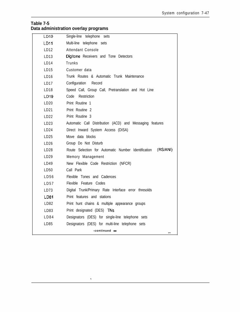
System configuration 7-47
Table 7-5Data administration overlay programs
LDlO
LD11
LD12
LD13
LD14
LD15
LD16
LD17
LD18
LD19
LD20
LD21
LD22
LD23
LD24
LD25
LD26
LD28
LD29
LD49
LD50
L D 5 6
L D 5 7
LD73
LD81
LD82
LD83
L D 8 4
LD85
Single-line telephone sets
Multi-line telephone sets
Attendant Console
Digitone Receivers and Tone Detectors
Trunks
Customer data
Trunk Routes & Automatic Trunk Maintenance
Configuration Record
Speed Call, Group Call, Pretranslation and Hot Line
Code Restriction
Print Routine 1
Print Routine 2
Print Routine 3
Automatic Call Distribution (ACD) and Messaging features
Direct Inward System Access (DISA)
Move data blocks
Group Do Not Disturb
Route Selection for Automatic Number Identification (RSANI)
Memory Management
New Flexible Code Restriction (NFCR)
Call Park
Flexible Tones and Cadences
Flexible Feature Codes
Digital Trunk/Primary Rate Interface error thresolds
Print features and stations
Print hunt chains & multiple appearance groups
Print designated (DES) TNs
Designators (DES) for single-line telephone sets
Designators (DES) for multi-line telephone sets
-continued - _-
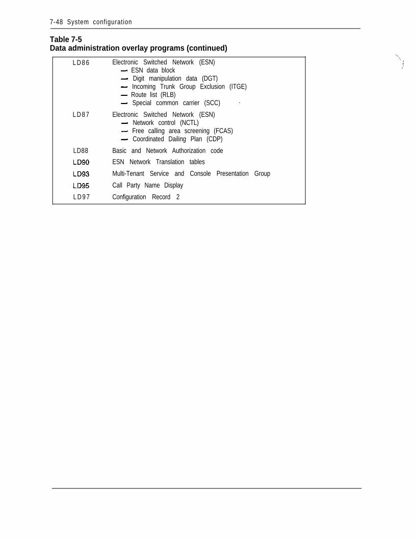
7-48 System configuration
Table 7-5Data administration overlay programs (continued)
L D 8 6
L D 8 7
LD88
Electronic Switched Network (ESN)- ESN data block- Digit manipulation data (DGT)- Incoming Trunk Group Exclusion (ITGE)- Route list (RLB)- Special common carrier (SCC) -
Electronic Switched Network (ESN)- Network control (NCTL)- Free calling area screening (FCAS)- Coordinated Dailing Plan (CDP)
Basic and Network Authorization code
ESN Network Translation tables
Multi-Tenant Service and Console Presentation Group
Call Party Name Display
L D 9 7 Configuration Record 2
-‘\.:,:
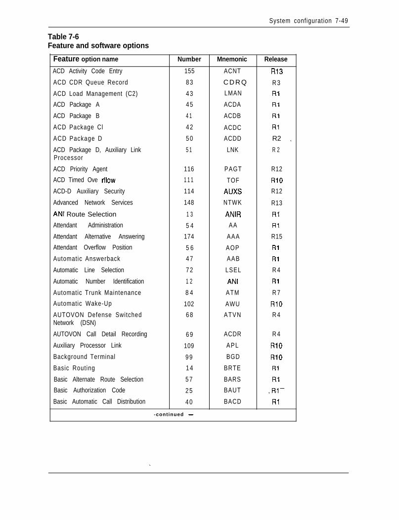
System configuration 7-49
Table 7-6Feature and software options
Feature option name Number Mnemonic Release
ACD Activity Code Entry 155 ACNT RI3
ACD CDR Queue Record 8 3 CDRQ R 3
ACD Load Management (C2) 4 3 LMAN Rl
ACD Package A 4 5 ACDA Rl
ACD Package B 4 1 ACDB Rl
ACD Package Cl 4 2 ACDC Rl
ACD Package D 5 0 ACDD R2 _
ACD Package D, Auxiliary Link 5 1 LNK R 2Processor
ACD Priority Agent 116 PAGT R12
ACD Timed Ove tflow 1 1 1 TOF RlO
ACD-D Auxiliary Security 114 AUXS R12
Advanced Network Services 148 NTWK R13
ANI Route Selection 1 3 ANIR Rl
Attendant Administration 5 4 AA Rl
Attendant Alternative Answering 174 AAA R15
Attendant Overflow Position 5 6 AOP Rl
Automatic Answerback 4 7 AAB Rl
Automatic Line Selection 7 2 LSEL R 4
Automatic Number Identification 1 2 ANI Rl
Automatic Trunk Maintenance 8 4 ATM R 7
Automatic Wake-Up 102 AWU RlO
AUTOVON Defense Switched 6 8 ATVN R 4Network (DSN)
AUTOVON Call Detail Recording 6 9 ACDR R 4
Auxiliary Processor Link 109 APL RlO
Background Terminal 9 9 BGD RlO
Basic Routing 1 4 BRTE Rl
Basic Alternate Route Selection 5 7 BARS Rl
Basic Authorization Code 2 5 BAUT , R.l--
Basic Automatic Call Distribution 4 0 BACD Rl
-continued -
. .
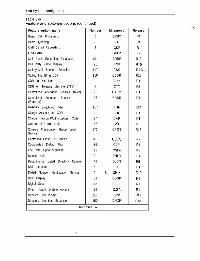
7-50 System configuration
Table 7-6Feature and software options (continued)
Feature option name Number Mnemonic Release
Basic Call Processing 0 BASIC Ri
Basic Queuing 2 8 BQUE, Rl
Call Detai l Recording 4 CDR Rl
Call Park 3 3 CPRK R 2
Call Detail Recording Expansion 1 5 1 CDRE R13
Call Party Name Display 9 5 CPND RlO
Call-by-Call Service Selection 117 CBC R13 _
Calling line ID in CDR 118 CCDR R13
CDR on Data Link 6 CLNK Rl
CDR on Teletype Machine (TTY) 5 CTY Rl
Centralized Attendant Services (Main) 2 6 CASM Rl
Centralized Attendant Services 2 7 CASR Rl(Remote)
Centrex Switchhook Flash 157 THF R14
Charge Account for CDR 2 3 CHG Rl
Charge Account/Authorization Code 2 4 CAB Rl
Command Status Link 7 7 CSL R 8
Console Presentation Group Level 1 7 2 CPGS R15Services
Controlled Class Of Service 8 1 ccos R 7Coordinated Dialing Plan 5 9 CDP Rl
CSL with Alpha Signaling 8 5 CSLA R 8
Deluxe Hold 7 1 DHLD R 4
Departmental Listed Directory Number 7 6 DLDN R5Dial Intercom 2 1 DI Rl
Dialed Number Identification Service 9 8 DNIS RlO
Digit Display 1 9 DDSP Rl
Digital Sets 8 8 DSET R 7
Direct Inward System Access 2 2 DISA Rl
Directed Call Pickup 115 DCP R12-
Directory Number Expansion 150 DNXP -R13
-continued -
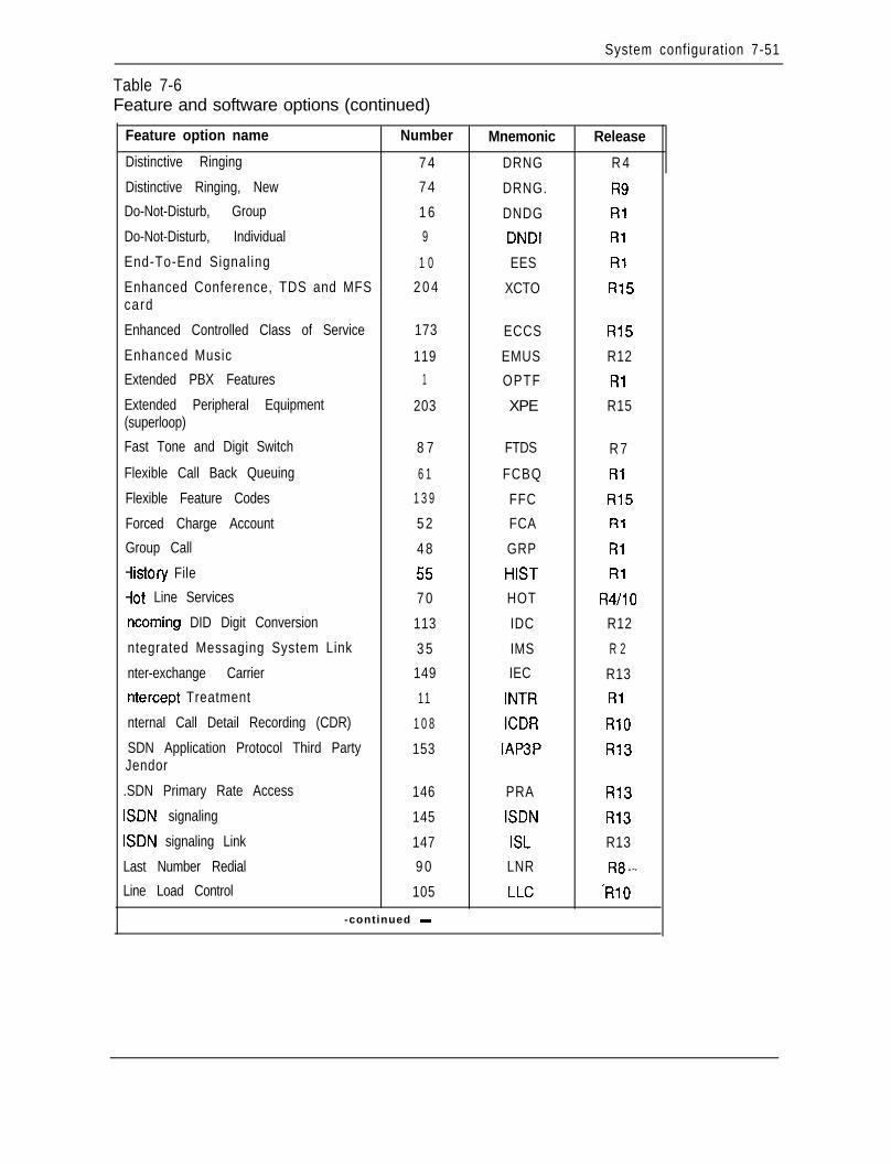
System configuration 7-51
Table 7-6Feature and software options (continued)
Feature option name Number Mnemonic Release
Distinctive Ringing 7 4 DRNG R 4
Distinctive Ringing, New 7 4 DRNG. R9Do-Not-Disturb, Group 1 6 DNDG RlDo-Not-Disturb, Individual 9 DNDI Rl
End-To-End Signaling 1 0 EES Rl
Enhanced Conference, TDS and MFS 2 0 4 XCTO R15card
Enhanced Controlled Class of Service 173 ECCS R15
Enhanced Music 119 EMUS R12Extended PBX Features 1 OPTF RlExtended Peripheral Equipment 203 XPE R15(superloop)
Fast Tone and Digit Switch 8 7 FTDS R 7
Flexible Call Back Queuing 6 1 FCBQ Rl
Flexible Feature Codes 1 3 9 FFC R15
Forced Charge Account 5 2 FCA Rl
Group Call 4 8 GRP Rl
iistory File 55 HIST Rl-lot Line Services 7 0 HOT R4/10ncoming DID Digit Conversion 113 IDC R12
ntegrated Messaging System Link 3 5 IMS R 2
nter-exchange Carrier 149 IEC R13ntercept Treatment 11 INTR Rl
nternal Call Detail Recording (CDR) 1 0 8 ICDR RlOSDN Application Protocol Third Party 153 IAPBP R13Jendor
.SDN Primary Rate Access 146 PRA R13ISDN signaling 145 ISDN R13ISDN signaling Link 147 ISL R13
Last Number Redial 9 0 LNR R8--
Line Load Control 105 LLC ‘RlO
-continued -
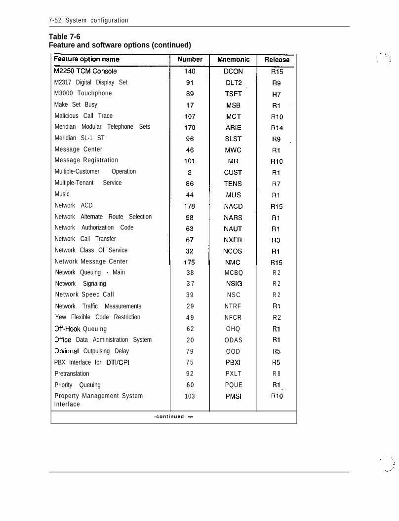
7-52 System configuration
Table 7-6Feature and software options (continued)
M2317 Digital Display Set
M3000 Touchphone
Make Set Busy
Malicious Call Trace
Meridian Modular Telephone Sets
Meridian SL-1 ST
Message Center
Message Registration
Multiple-Customer Operation
Multiple-Tenant Service
Music
Network ACD
Network Alternate Route Selection
Network Authorization Code
Network Call Transfer
Network Class Of Service
Network Message Center
Network Queuing - Main
Network Signaling
Network Speed Call
Network Traffic Measurements
Yew Flexible Code Restriction
Dff-Hook Queuing
Office Data Administration System
Dptional Outpulsing Delay
PBX Interface for DTVCPI
Pretranslation
Priority Queuing
Property Management SystemInterface
3 8
3 7
3 9
2 9
4 9
6 2
2 0
7 9
7 5
9 2
6 0
103
MCBQ
NSIG
NSC
NTRF
NFCR
OHQ
ODAS
OOD
PBXI
PXLT
PQUE
PMSI
R 2
R 2
R 2
Rl
R 2
Rl
Rl
R5
R5
R 8
Rl _--RiO
-continued -
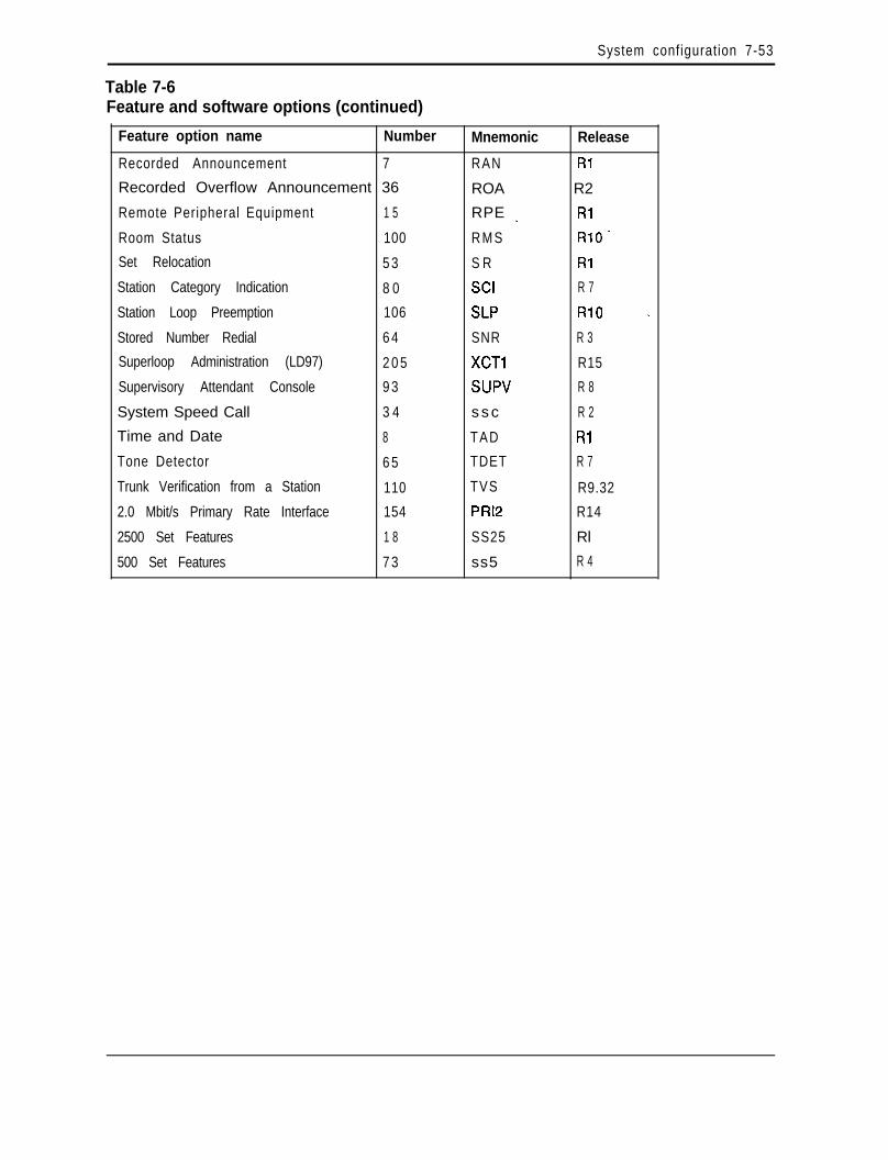
System configuration 7-53
Table 7-6Feature and software options (continued)
Feature option name Number Mnemonic Release
Recorded Announcement 7 RAN Ri
Recorded Overflow Announcement 36 ROA R2
Remote Peripheral Equipment 1 5 RPE _ Rl
Room Status 100 R M S R10.
Set Relocation 5 3 S R Rl
Station Category Indication 8 0 SCI R 7
Station Loop Preemption 106 SLP RlO _
Stored Number Redial 6 4 SNR R 3
Superloop Administration (LD97) 2 0 5 XCTl R15
Supervisory Attendant Console 9 3 SUPV R 8
System Speed Call 3 4 s s c R 2
Time and Date 8 TAD Rl
Tone Detector 6 5 TDET R 7
Trunk Verification from a Station 110 TVS R9.32
2.0 Mbit/s Primary Rate Interface 154 PRl2 R14
2500 Set Features 1 8 SS25 Rl
500 Set Features 7 3 ss5 R 4
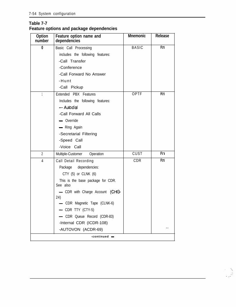
7-54 System configuration
Table 7-7Feature options and package dependencies
Option Feature option name and Mnemonic Releasenumber dependencies
0 Basic Call Processing BASIC Rl
includes the following features:
-Call Transfer
-Conference
-Call Forward No Answer
- H u n t
-Call Pickup
1 Extended PBX Features OPTF Rl
Includes the following features:
- Autodial
-Call Forward All Calls
- Override
- Ring Again
-Secretarial Filtering
-Speed Call
-Voice Call
2 Multiple-Customer Operation CUST Rl
4 Call Detai l Recording CDR Rl
Package dependencies:
CTY (5) or CLNK (6)
This is the base package for CDR.See also
- CDR with Charge Account (CHG-24)- CDR Magnetic Tape (CLNK-6)
- CDR TTY (CTY-5)
- CDR Queue Record (CDR-83)
-Internal CDR (ICDR-108)
-AUTOVON (ACDR-69) --
-continued -
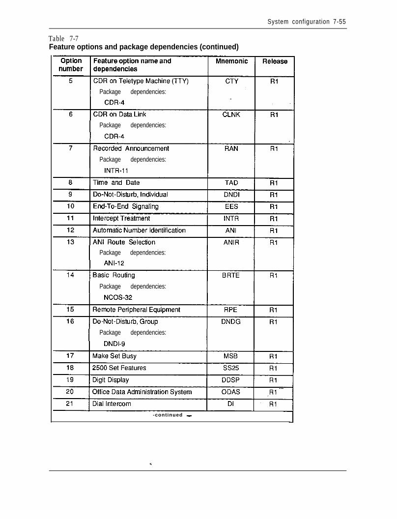
System configuration 7-55
Table 7-7Feature options and package dependencies (continued)
Package dependencies:
Package dependencies:
Package dependencies:
Package dependencies:
Package dependencies:
Package dependencies:
-continued -
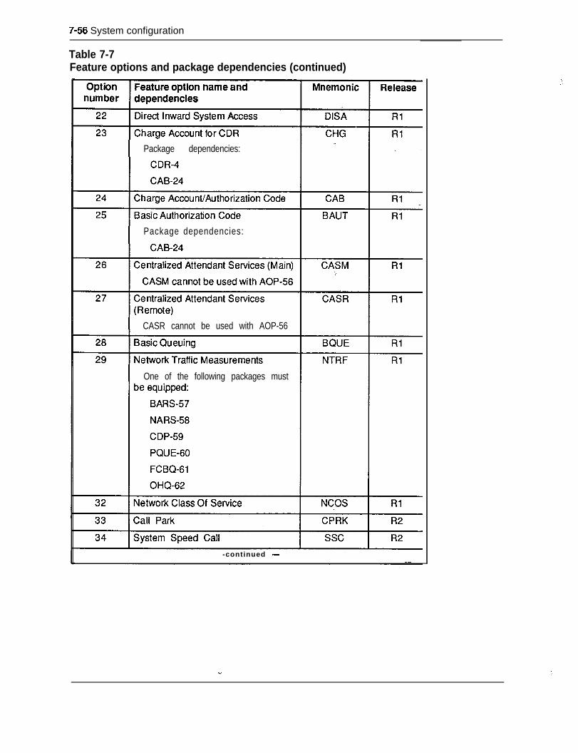
9-56 System configuration
Table 7-7Feature options and package dependencies (continued)
Package dependencies:
Package dependencies:
CASR cannot be used with AOP-56
One of the following packages must
-continued -
.!
: ,
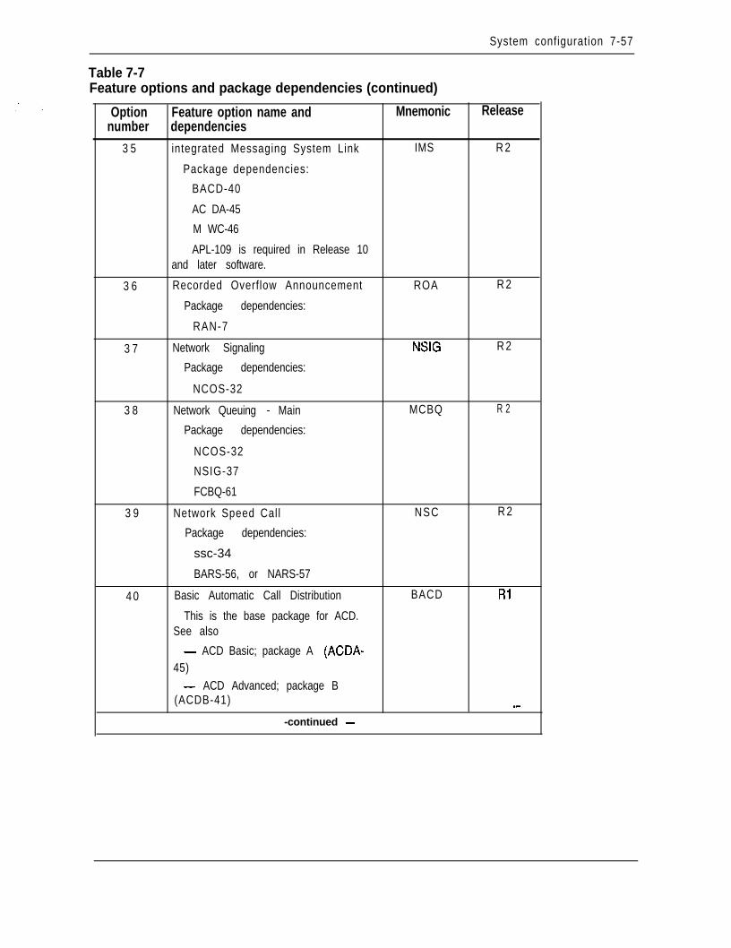
System configuration 7-57
Table 7-7Feature options and package dependencies (continued)
Option Feature option name and Mnemonicnumber dependencies
3 5 integrated Messaging System Link IMS
Package dependencies:
BACD-40
AC DA-45
M WC-46
APL-109 is required in Release 10and later software.
3 6 Recorded Overflow Announcement ROA
Package dependencies:
RAN-7
3 7 Network Signaling NSIG
Package dependencies:
NCOS-32
3 8 Network Queuing - Main MCBQ
Package dependencies:
NCOS-32
NSIG-37
FCBQ-61
3 9 Network Speed Call NSC
Package dependencies:
ssc-34
BARS-56, or NARS-57
4 0 Basic Automatic Call Distribution BACD
This is the base package for ACD.See also
- ACD Basic; package A (ACDA-45)- ACD Advanced; package B
(ACDB-41)
-continued -
Release
R 2
R 2
R 2
R 2
R 2
Rl
_-
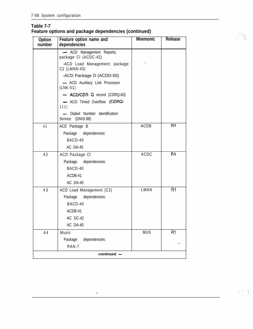
7-58 System configuration
Table 7-7Feature options and package dependencies (continued)
Option Feature option name and Mnemonicnumber dependencies
- ACD Management Reports;package Cl (ACDC-42)
-ACD Load Management; package -C2 (LMAN-43)
-ACD Package D (ACDD-50)
- ACD Auxiliary Link Processor(LNK-51)
- ACD/CDR Q record (CDRQ-83)
- ACD Timed Overflow (CDRQ-1 1 1 )
- Dialed Number IdentificationService (DNIS-98)
4 1 ACD Package B ACDB
Package dependencies:
BACD-40
AC DA-45
4 2 ACD Package Cl ACDC
Package dependencies:
BACD-40
ACDB-41
AC DA-45
4 3 ACD Load Management (C2) LMAN
Package dependencies:
BACD-40
ACDB-41
AC DC-42
AC DA-45
4 4 Music MUS
Package dependencies:
RAN-7
-continued -
Release
Rl
RI
Rl
Rl
--
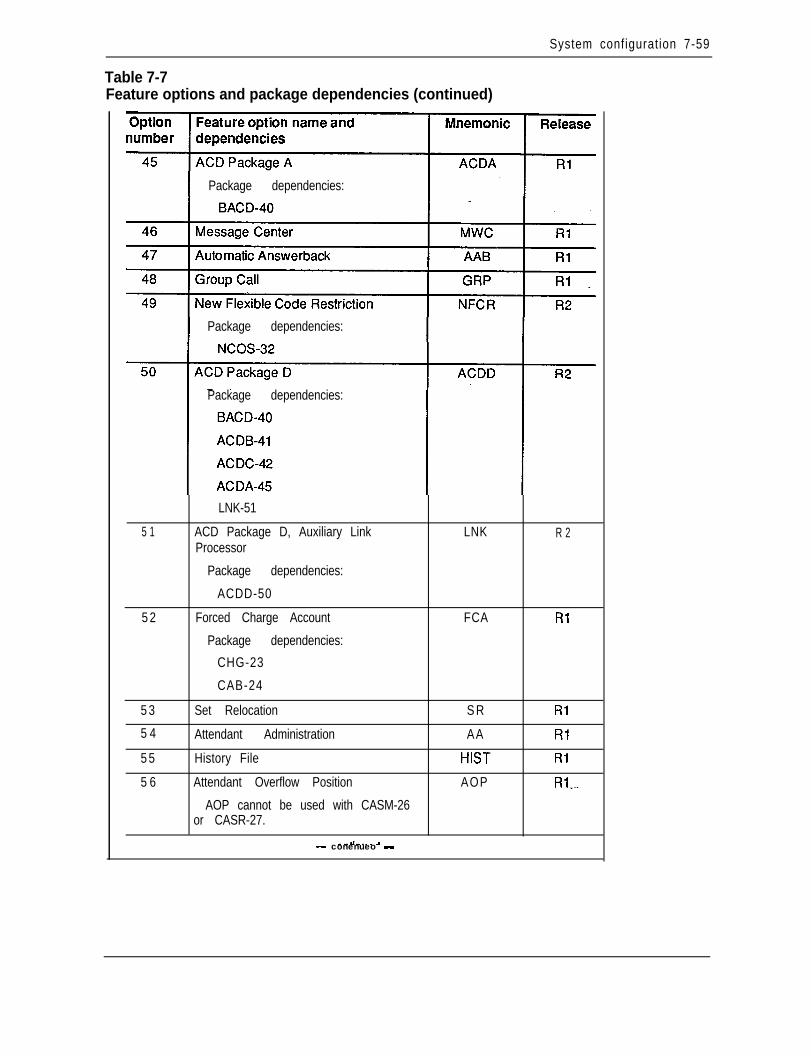
System configuration 7-59
Table 7-7Feature options and package dependencies (continued)
- conenueo -
Package dependencies:
Package dependencies:
Package dependencies:
5 1
5 2
5 3
5 4
5 5
5 6
LNK-51
ACD Package D, Auxiliary LinkProcessor
Package dependencies:
ACDD-50
Forced Charge Account
Package dependencies:
CHG-23
CAB-24
Set Relocation
Attendant Administration
History File
Attendant Overflow Position
AOP cannot be used with CASM-26or CASR-27.
- --d-.~- 3
LNK R 2
FCA Rl
S R Rl
AA Rl
HIST Rl
AOP Rl--

7-60 System configuration
Table 7-7Feature options and package dependencies (continued)
Option Feature option name and Mnemonic Releasenumber dependencies
5 7 Basic Alternate Route Selection BARS Rl
Package dependencies:
BRTE-14
NCOS-32
5 8 Network Alternate Route Selection NARS Rl
Package dependencies:
BRTE-14
NCOS-32
5 9 Coordinated Dialing Plan CDP Rl
Package dependencies:
BRTE-14
NCOS-32
FCBQ-61
6 0 Priority Queuing PQUE Rl
Package dependencies:
NCOS-32
6 1 Flexible Call Back Queuing FCBQ Rl
Package dependencies:
BQU E-28
BARS (57) or NARS (58) or CDP(59)
6 2 Off-Hook Queuing O H Q Rl
Package dependencies:
BQUE-28
BARS-57 or NARS-58
8 3 Network Authorization Code NAUT Rl
Package dependencies:
CAB-24 --BAUT-25
BARS (57) or NARS (58) or CDP(59)
-continued -
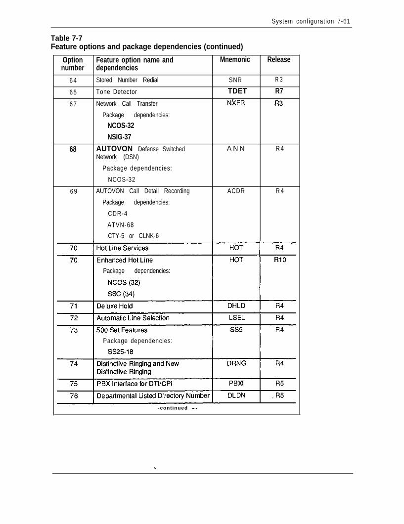
System configuration 7-61
Table 7-7Feature options and package dependencies (continued)
Option Feature option name and Mnemonicnumber dependencies
6 4 Stored Number Redial SNR
6 5 Tone Detector TDET
6 7 Network Call Transfer NXFR
Package dependencies:
NCOS-32NSIG-37
68 AUTOVON Defense Switched A N NNetwork (DSN)
Package dependencies:
NCOS-32
6 9 AUTOVON Call Detail Recording ACDR
Package dependencies:
CDR-4
ATVN-68
CTY-5 or CLNK-6
Release
R 3
R7.R3
R 4
R 4
Package dependencies:
Package dependencies:
-continued -
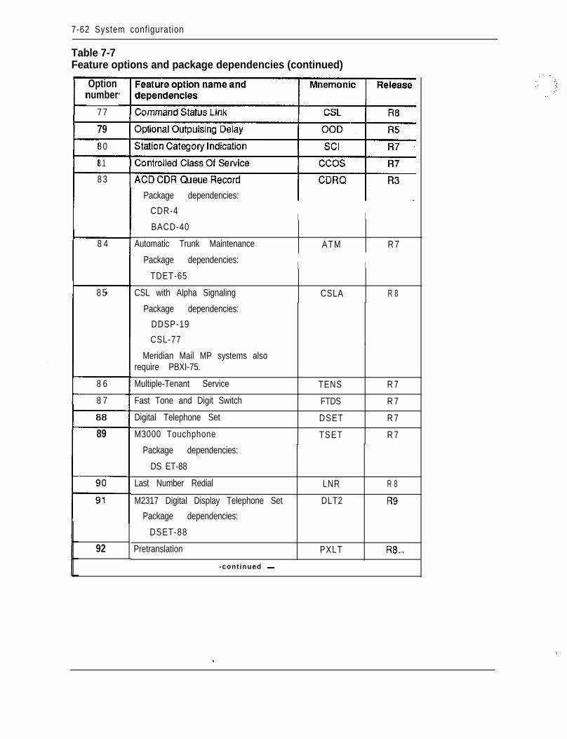
7-62 System configuration
Table 7-7Feature options and package dependencies (continued)
Optionnumber
7 7
798 0
8 1
8 3
8 4
8 5
8 6
8 7
89
92
Package dependencies:
CDR-4I I
BACD-40
Automatic Trunk Maintenance ATM R 7
Package dependencies:
TDET-65
CSL with Alpha Signaling
I I
CSLA R 8
Package dependencies:
DDSP-19
CSL-77
Meridian Mail MP systems alsorequire PBXI-75.
Multiple-Tenant Service
Fast Tone and Digit Switch
Digital Telephone Set
M3000 Touchphone
TENS R 7
FTDS R 7
DSET R 7
TSET R 7
Package dependencies:
DS ET-88
Last Number Redial
M2317 Digital Display Telephone Set
Package dependencies:
DSET-88
Pretranslation
-continued -
LNR R 8
DLT2 R9
PXLT R8-
\.. .
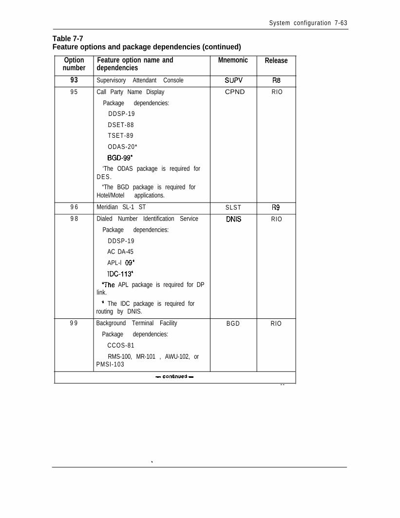
System configuration 7-63
Table 7-7Feature options and package dependencies (continued)
Option Feature option name and Mnemonic Releasenumber dependencies
93 Supervisory Attendant Console SUPV R8
9 5 Call Party Name Display CPND RIO
Package dependencies:
DDSP-19
DSET-88
TSET-89
ODAS-20*
BGD-99*
‘The ODAS package is required forDES.
“The BGD package is required forHotel/Motel applications.
9 6 Meridian SL-1 ST SLST R9
9 8 Dialed Number Identification Service DNIS RIO
Package dependencies:
DDSP-19
AC DA-45
APL-l 09*
IDC-113*
7he APL package is required for DPlink.
* The IDC package is required forrouting by DNIS.
9 9 Background Terminal Facility BGD RIO
Package dependencies:
CCOS-81
RMS-100, MR-101 , AWU-102, orPMSI-103
_. m- connnuea -
- -
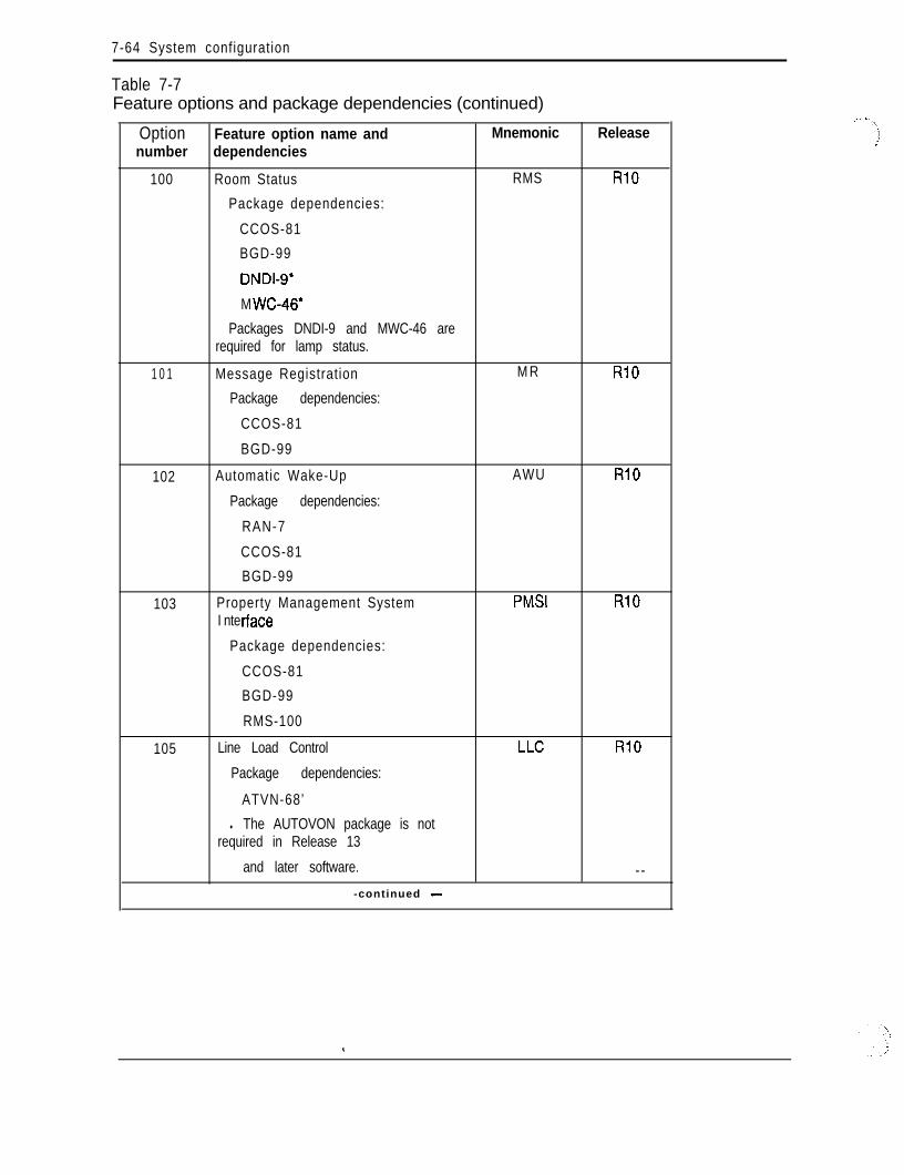
7-64 System configuration
Table 7-7Feature options and package dependencies (continued)
Option Feature option name and Mnemonicnumber dependencies
100 Room Status RMS
Package dependencies:
CCOS-81
BGD-99
DNDI-9*
M WC-46*
Packages DNDI-9 and MWC-46 arerequired for lamp status.
1 0 1 Message Registration M R
Package dependencies:
CCOS-81
BGD-99
102 Automatic Wake-Up AWU
Package dependencies:
RAN-7
CCOS-81
BGD-99
103 Property Management System PMSII nte f-face
Package dependencies:
CCOS-81
BGD-99
RMS-100
105 Line Load Control LLC
Package dependencies:
ATVN-68’
l The AUTOVON package is notrequired in Release 13
and later software.
-continued -
Release
RlO
RlO
RlO
RlO
RlO
--
. .
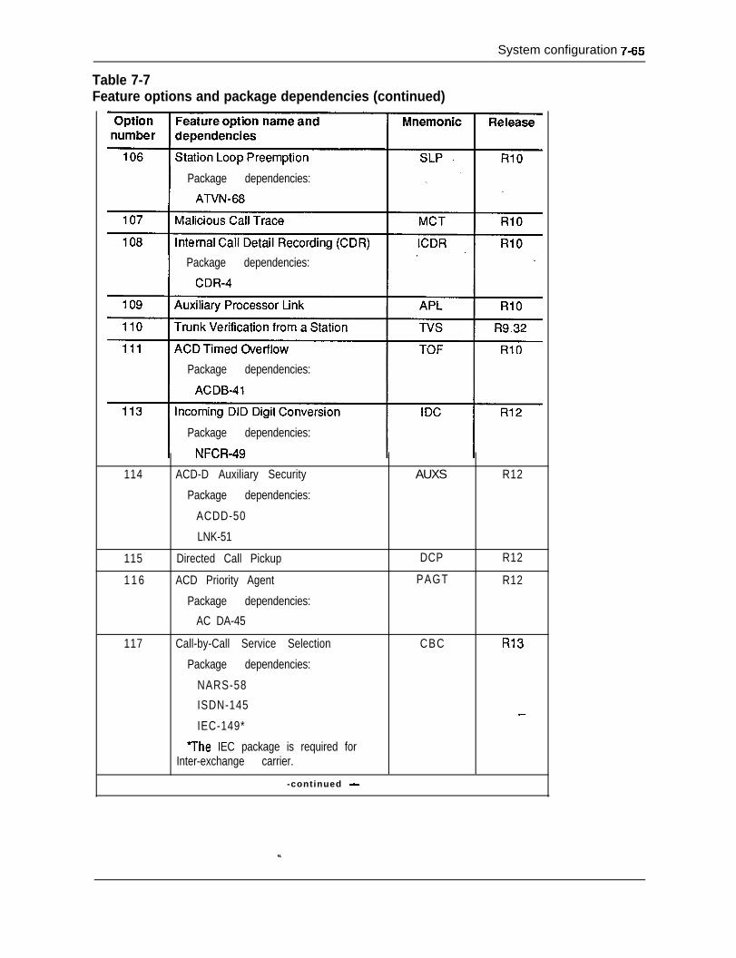
Table 7-7Feature options and package dependencies (continued)
System configuration 7-65
Package dependencies:
Package dependencies:
Package dependencies:
Package dependencies:
114 ACD-D Auxiliary Security AUXS R12
Package dependencies:
ACDD-50
LNK-51
115 Directed Call Pickup DCP R12
1 1 6 ACD Priority Agent PAGT R12
Package dependencies:
AC DA-45
117 Call-by-Call Service Selection CBC R13
Package dependencies:
NARS-58
ISDN-145 _-IEC-149*
7he IEC package is required forInter-exchange carrier.
-continued -
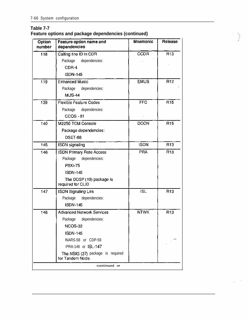
7-66 System configuration
Table 7-7Feature options and package dependencies (continued)
Package dependencies:
Package dependencies:
Package dependencies:
Package dependencies:
Package dependencies:
Package dependencies:
NARS-58 or CDP-59
PRA-146 or EL-147
package is required
-continued -
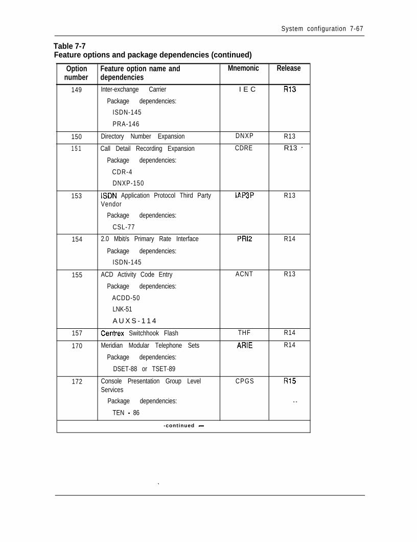
System configuration 7-67
Table 7-7Feature options and package dependencies (continued)
Option Feature option name and Mnemonicnumber dependencies
149 Inter-exchange Carrier I E C
Package dependencies:
ISDN-145
PRA-146
150 Directory Number Expansion DNXP
1 5 1 Call Detail Recording Expansion CDRE
Package dependencies:
CDR-4
DNXP-150
153 ISDN Application Protocol Third Party IAP3PVendor
Package dependencies:
CSL-77
154 2.0 Mbit/s Primary Rate Interface PRl2
Package dependencies:
ISDN-145
155 ACD Activity Code Entry ACNT
Package dependencies:
ACDD-50
LNK-51
A U X S - 1 1 4 .~
157 Centrex Switchhook Flash THF
170 Meridian Modular Telephone Sets ARIE
Package dependencies:
DSET-88 or TSET-89
172 Console Presentation Group Level CPGSServices
Package dependencies:
TEN - 86
-continued -
Release
R13
R13
R13 -
R13
R14
R13
R14
R14
R15
- -
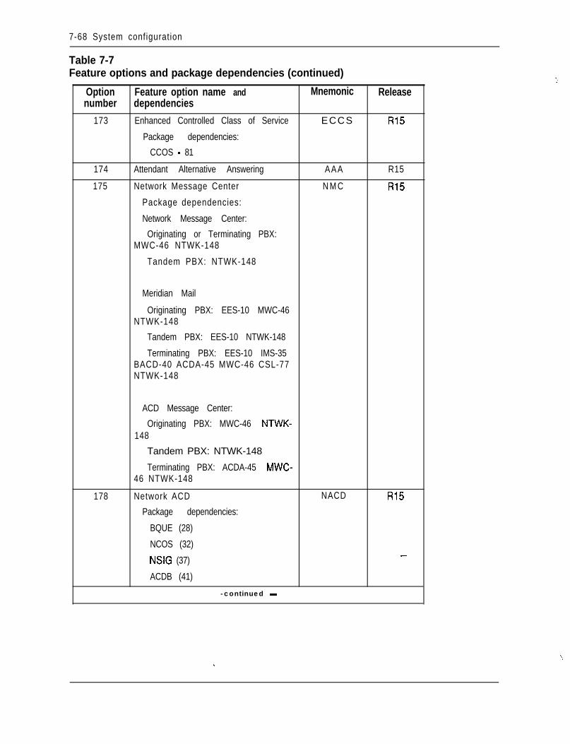
7-68 System configuration
Table 7-7Feature options and package dependencies (continued)
Option Feature option name and Mnemonicnumber dependencies
173 Enhanced Controlled Class of Service ECCS
Package dependencies:
CCOS - 81
174 Attendant Alternative Answering AAA
175 Network Message Center N M C
Package dependencies:
Network Message Center:
Originating or Terminating PBX:MWC-46 NTWK-148
Tandem PBX: NTWK-148
Release
R15
R15
R15
Meridian Mail
Originating PBX: EES-10 MWC-46NTWK-148
Tandem PBX: EES-10 NTWK-148
Terminating PBX: EES-10 IMS-35BACD-40 ACDA-45 MWC-46 CSL-77NTWK-148
178
ACD Message Center:
Originating PBX: MWC-46 NTWK-148
Tandem PBX: NTWK-148
Terminating PBX: ACDA-45 MWC-46 NTWK-148
Network ACD
Package dependencies:
BQUE (28)
NCOS (32)
NSIG (37)
ACDB (41)
-continued -
NACD R15
_-
5
‘S..
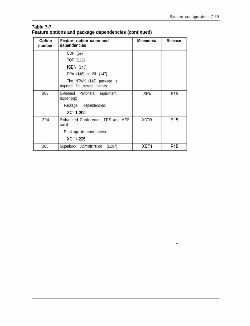
System configuration 7-69
Table 7-7Feature options and package dependencies (continued)
Option Feature option name and Mnemonic Releasenumber dependencies
CDP (59)
TOF (111)
ISDN (145)
PRA (146) or ISL (147)
The NTWK (148) package isrequired for remote targets.
203 Extended Peripheral Equipment XPE R15(superloop)
Package dependencies:
XCTl -205
2 0 4 Enhanced Conference, TDS and MFS XCTO R15card
Package dependencies:
XCTl -205
205 Superloop Administration (LD97) XCTl R15
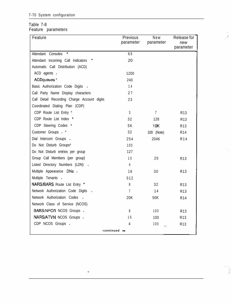
7-70 System configuration
Table 7-8Feature parameters
Feature Previous N e w Release forparameter parameter new
parameterAttendant Consoles * 6 3
Attendant Incoming Call Indicators * 20 -
Automatic Call Distribution (ACD)
ACD agents l 1200
ACDqueues * 240
Basic Authorization Code Digits l 1 4
Call Party Name Display characters 2 7
Call Detail Recording Charge Account digits 2 3
Coordinated Dialing Plan (CDP)
CDP Route List Entry * 3 7 R13CDP Route List Index * 3 2 128 R13CDP Steering Codes * 5K 10K R13
Customer Groups l * 3 2 100 (Note) R14
Dial Intercom Groups l 2 5 4 2046 R 1 4Do Not Disturb Groups* 1 0 0
Do Not Disturb entries per group 127
Group Call Members (per group) 1 0 2 0 R13Listed Directory Numbers (LDN) l 4
Multiple Appearance DNs l 1 6 3 0 R13
Multiple Tenants l 5 1 2
NARS/BARS Route List Entry * 8 3 2 R13Network Authorization Code Digits l 7 1 4 R13Network Authorization Codes l 20K 50K R14Network Class of Service (NCOS)
BARSNFCR NCOS Groups l 8 1 0 0 R13NARSATVN NCOS Groups l 1 6 100 R13CDP NCOS Groups l 4 1 0 0 R13--
-continued -
\
;Y’
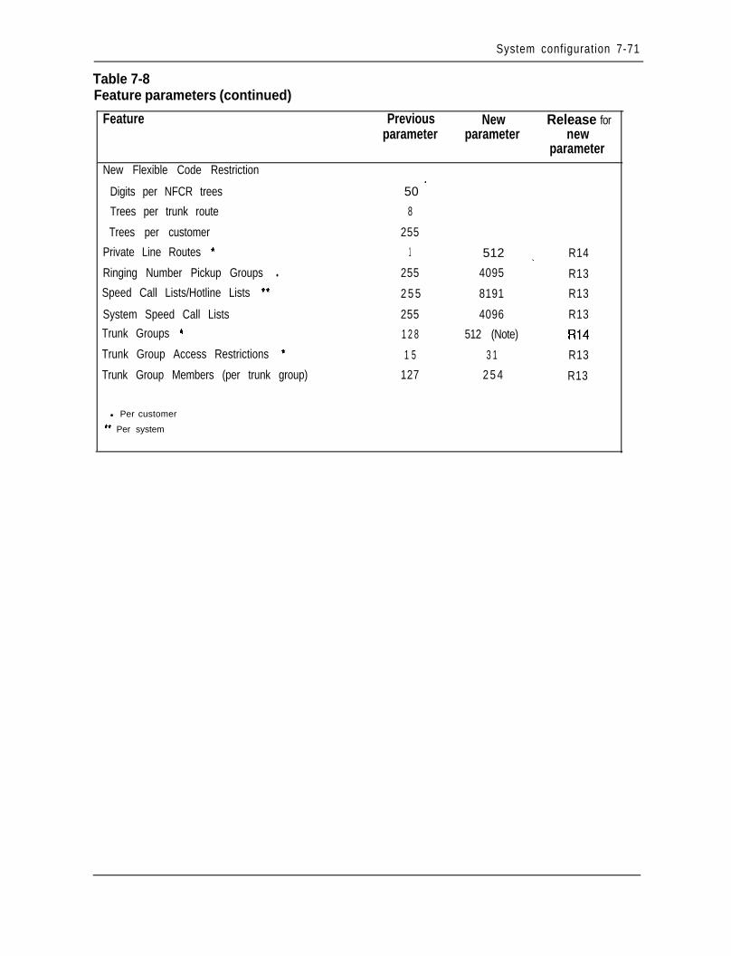
System configuration 7-71
Table 7-8Feature parameters (continued)
Feature
New Flexible Code Restriction
Digits per NFCR trees
Trees per trunk route
Trees per customer
Private Line Routes *
Ringing Number Pickup Groups l
Speed Call Lists/Hotline Lists **
System Speed Call ListsTrunk Groups *
Trunk Group Access Restrictions *
Trunk Group Members (per trunk group)
Previous New Release forparameter parameter new
parameter
50 -
8
255
1 512 _ R14
255 4095 R13
2 5 5 8191 R13
255 4096 R13
1 2 8 512 (Note) R14
1 5 3 1 R13
127 2 5 4 R13
l Per customer
‘* Per system
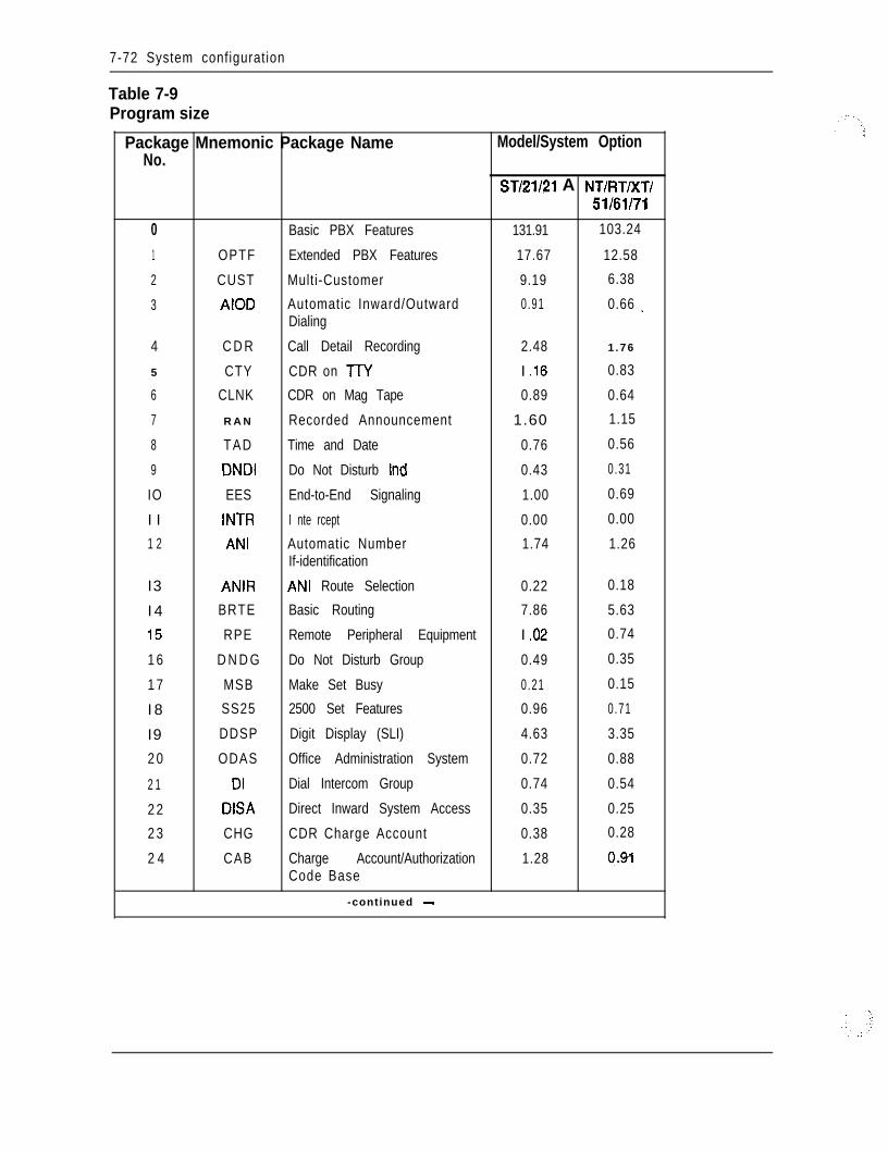
7-72 System configuration
Table 7-9Program size
Package Mnemonic Package Name Model/System OptionNo.
ST/21/?1 A NT/RT/XT/51/61/71
0 Basic PBX Features 131.91 103.24
1 OPTF Extended PBX Features 17.67 12.58
2 CUST Multi-Customer 9.19 6.38
3 AIOD Automatic Inward/Outward 0.91 0.66 _Dialing
4 C D R Call Detail Recording 2.48 1 .76
5 CTY CDR on TTY I .16 0.83
6 CLNK CDR on Mag Tape 0.89 0.64
7 R A N Recorded Announcement 1.60 1.15
8 TAD Time and Date 0.76 0.56
9 DNDI Do Not Disturb Ind 0.43 0.31
IO EES End-to-End Signaling 1.00 0.69
I I INTR I nte rcept 0.00 0.00
1 2 ANI Automatic Number 1.74 1.26If-identification
I3 ANIR ANI Route Selection 0.22 0.18
I 4 BRTE Basic Routing 7.86 5.63
I5 RPE Remote Peripheral Equipment I .02 0.74
1 6 D N D G Do Not Disturb Group 0.49 0.35
1 7 MSB Make Set Busy 0.21 0.15
I 8 SS25 2500 Set Features 0.96 0.71
I9 DDSP Digit Display (SLI) 4.63 3.35
2 0 ODAS Office Administration System 0.72 0.88
2 1 DI Dial Intercom Group 0.74 0.54
2 2 DISA Direct Inward System Access 0.35 0.25
2 3 CHG CDR Charge Account 0.38 0.28
2 4 CAB Charge Account/Authorization 1.28 q.9Code Base
-continued -
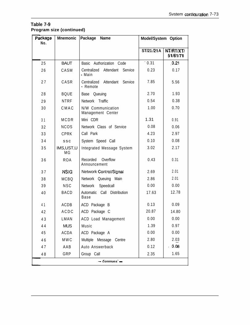
Svstem confiauration 7-73
Table 7-9Program size (continued)
ckage Mnemonic Package Name Model/System OptionNo.
2 5
2 6
2 7
2 8
2 9
3 0
3 1
3 2
3 3
3 4
3 5
3 6
3 7
3 8
3 9
4 0
4 1
4 2
4 3
4 4
4 5
4 6
4 7
4 8
ST/21 121 A NT/FIT/XT/51/61/71
BAUT Basic Authorization Code - 0.31 .0.21
CASM Centralized Attendant Service 0.23 0.17- Main
CASR Centralized Attendant Service 7.85 5.56- Remote
BQUE Base Queuing 2.70 1.93
NTRF Network Traffic 0.54 0.38
C M A C N/W Communication 1.00 0.70Management Center
M C D R Mini CDR 1.31 0.91
NCOS Network Class of Service 0.08 0.06
CPRK Call Park 4.23 2.97
s s c System Speed Call 0.10 0.08
IMS,UST,U Integrated Message System 3.02 2.17MG
ROA Recorded Overflow 0.43 0.31Announcement
NSIG Network ControVSignal 2.69 2.01
MCBQ Network Queuing Main 2.86 2.01
NSC Network Speedcall 0.00 0.00
BACD Automatic Call Distribution 17.63 12.78Base
ACDB ACD Package B 0.13 0.09
A C D C ACD Package C 20.87 14.80
LMAN ACD Load Management 0.00 0.00
MUS Music 1.39 0.97
ACDA ACD Package A 0.00 0.00
M W C Multiple Message Centre 2.80 2.03
AAB Auto Answerback 0.12 ’ 0.08
GRP Group Call 2.35 1.65_e *
- connnuea -
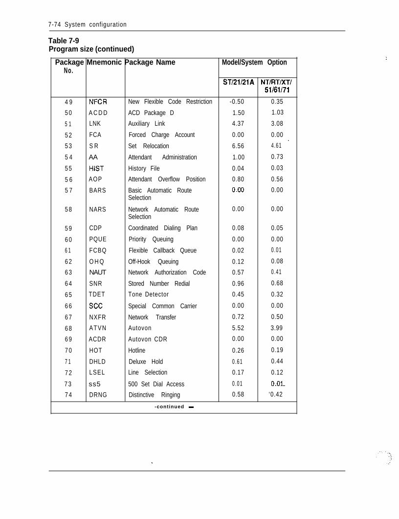
7-74 System configuration
Table 7-9Program size (continued)
Package Mnemonic Package Name Model/System OptionNo.
ST/21/21A NT/RT/XT/51/61/71
4 9 NFCR New Flexible Code Restriction -0.50 0.35
5 0 A C D D ACD Package D 1.50 1.03
5 1 LNK Auxiliary Link 4.37 3.08
5 2 FCA Forced Charge Account 0.00 0.00
_5 3 S R Set Relocation 6.56 4.61
5 4 AA Attendant Administration 1.00 0.73
5 5 HIST History File 0.04 0.03
5 6 AOP Attendant Overflow Position 0.80 0.56
5 7 BARS Basic Automatic Route .o.oo 0.00Selection
5 8 NARS Network Automatic Route 0.00 0.00Selection
5 9 CDP Coordinated Dialing Plan 0.08 0.05
6 0 PQUE Priority Queuing 0.00 0.00
6 1 FCBQ Flexible Callback Queue 0.02 0.01
6 2 O H Q Off-Hook Queuing 0.12 0.08
6 3 NAUT Network Authorization Code 0.57 0.41
6 4 SNR Stored Number Redial 0.96 0.68
6 5 TDET Tone Detector 0.45 0.32
6 6 see Special Common Carrier 0.00 0.00
6 7 NXFR Network Transfer 0.72 0.50
6 8 ATVN Autovon 5.52 3.99
6 9 ACDR Autovon CDR 0.00 0.00
7 0 HOT Hotline 0.26 0.19
7 1 DHLD Deluxe Hold 0.61 0.44
7 2 LSEL Line Selection 0.17 0.12
7 3 ss5 500 Set Dial Access 0.01 O.Ol-
7 4 DRNG Distinctive Ringing 0.58 ‘0.42
-continued -
i
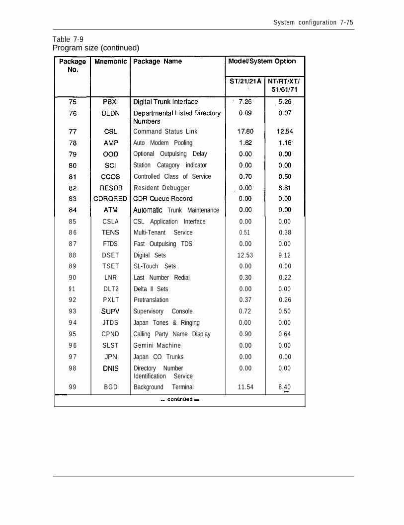
System configuration 7-75
Table 7-9Program size (continued)
Command Status Link
Auto Modem Pooling
Optional Outpulsing Delay
Station Catagory indicator
Controlled Class of Service
Resident Debugger
8 5
8 6
8 7
8 8
8 9
9 0
9 1
9 2
9 3
9 4
9 5
9 6
9 7
9 8
9 9
CSLA
TENS
FTDS
DSET
TSET
LNR
DLT2
PXLT
SUPV
JTDS
CPND
SLST
JPN
DNIS
BGD
Automatfc Trunk Maintenance
CSL Application Interface
Multi-Tenant Service
Fast Outpulsing TDS
Digital Sets
SL-Touch Sets
Last Number Redial
Delta II Sets
Pretranslation
Supervisory Console
Japan Tones & Ringing
Calling Party Name Display
Gemini Machine
Japan CO Trunks
Directory NumberIdentification Service
Background Terminal. . .
0.00 0.00
0.51 0.38
0.00 0.00
12.53 9.12
0.00 0.00
0.30 0.22
0.00 0.00
0.37 0.26
0.72 0.50
0.00 0.00
0.90 0.64
0.00 0.00
0.00 0.00
0.00 0.00
11.54 8.40-- conunuea -
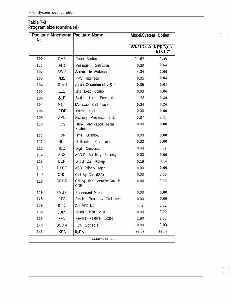
7-76 System configuration
Table 7-9Program size (continued)
Package Mnemonic Package NameNo.
100 RMS Room Status
1 0 1 M R Message Restriction
102 AWU Automatfc Wakeup
103 PMSI PMS Interface
104 OPAO Japan Outpulse of l 8 #
105 LLC Line Load Control
106 SLP Station Loop Preemption
107 M C T Malicous Call Trace
108 ICDR Internal Call
109 APL Auxiliary Processor Link
110 TVS Trunk Verification FromStation
1 1 1 TOF Time Overflow
112 NKL Notification Key Lamp
113 IDC Digit Conversion
114 AUX ACD-D Auxiliary Security
115 DCP Direct Call Pickup
1 1 6 PAGT ACD Priority Agent
1 1 7 CBC Call By Call (ISA)
118 C C D R Calling tine Identification inCDR
119 EMUS Enhanced Music
125 FTC Flexible Tones & Cadences
129 DT12 2.0 Mbit DTI
136 JDMI Japan Digital MUX
139 FFC Flexible Feature Codes
140 DCON TCM Console
145 ISDN ISDN
-continued -
Model/System Option
ST/21/21 A NT/RT/XT/U/61/71
- 1.67 .l.25
0.89 0.64
4.34 3.06
0.05 0.04
_0.05 0.04
0.08 0.06
1.23 0.89
0.34 0.24
0.00 0.00
5.07 3.71
0.00 0.00
0.00 0.00
0.00 0.00
0.44 0.31
0.00 0.00
0.19 0.14
0.00 0.00
0.00 0.00
0.00 0.00
0.00 0.00
0.00 0.00
8.57 6.12
0.00 0.00
2.80 2.02
0.00 0.g
35.28 -26.06
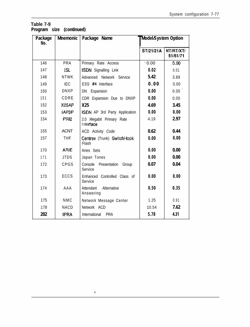
System configuration 7-77
Table 7-9Program size (continued)
PackageNo.
Mnemonic Package Name
146 PRA
147 ISL
148 NTWK
149 IEC
150 DNXP
1 5 1 C D R E
152 X25AP
153 IAP3P
154 PRl2
155 ACNT
157 THF
170 ARIE
1 7 1 JTDS
172 CPGS
173 ECCS
174 AAA
175 N M C
178 NACD
202 IPRA
Primary Rate Access
ISDN Signalling Link
Advanced Network Service
ESS #4 Interface
DN Expansion
CDR Expansion Due to DNXP
X25ISDN AP 3rd Party Application
2.0 Megabit Primary RateI nte r-face
ACD Activity Code
Centrex (Trunk) SwitchHookFlash
Aries Sets
Japan Tones
Console Presentation GroupService
Enhanced Controlled Class ofService
Attendant AlternativeAnswering
Network Message Center
Network ACD
International PRA
TModel/System Option
ST/21/21A
- 0.00
0.025.420 . 0 00.000.004.690.004.19
NT/FIT/XT/51/61/71
,o.oo0.01
3.89
0.00
0.00 _
0.00
3.450.002.97
0.62 0.440.00 0.00
0.000.000.07
0.000.000.04
0.00 0.00
0.50 0.35
1.25 0.91
10.54 7.625.78 4.31

8-1
Chapter 8 - Ordering informationContentsintroductionAutoquoteSystem optionsPackage conceptSL-1 system option 21, 21ASL-1 system option 51SL-1 system option 61SL-1 system option 71Peripheral expansionRemote Peripheral EquipmentSoftwareMeridian Modular TelephonesPower
6-l8-48-48-58-6
8-l 18-158-198-238-248-258-348-41
IntroductionOrdering Meridian 1 Communication Systems is a straightforward process.Modularity and flexibility permits each system to be individually configured to suitspecific applications. The necessary equipment and associated quantity depends uponthe system requirements which essentially fall into each of the following categories:- Hardware
. number and type of telephones (500/2500 type, digital telephones)
. number and type of trunks (CO, FX, TIE, DID, DTI/PRI)l number and type of data units (ADM, ASIM, HSDM). number of network resources necessary to meet the traffic requirements for the
various peripheral ports--
- Softwarel base software required to support the system. application software associated with the required optional features
8-2 Ordering information
- Power. optional AC or DC power distribution scheme
From these requirements, the following system elements and their respective quantitiesare calculated.
- System Structure9 Universal Equipment Modulesl Pedestal Assemblyl Top Cap Assembly
- Common Equipmentl Common Equipment Modules. Mass Storage Unit. Central Processing Unit. Memory Cards. Network Circuit Cards. Peripheral Signaling Cards. ConferenWI’DS Cards. Segmented Bus Extenders. Multigroup Extenders. 3-Port Extenders. Serial Data Interfaces. Bus Termination Units. Dummy Faceplates
- Peripheral Equipmentl Peripheral Equipment Modulesl Peripheral Controllersl Line Interface Cardsl Trunk Interface Cardsl Digitone Receiversl Data Interface Cardsl Digital Trunk Interfacesl Primary Rate Interfaces
- -
Ordering information 8-3
- Terminal Equipmentl Modular Digital Telephonesl 500/2500 Type Telephonesl Attendant Consolesl Key/Lamp Add-on Modules. Handsfree & Headset Modulesl Data Access Units ’
- Power EquipmentAC or DC Power Option48V RectifiersPower ConvertersLine Transfer UnitsReserve Power RequirementsRinging GeneratorsPower and System MonitorsCooling UnitsDistribution Units
- Software (RTU Fee)l Base Softwarel Optional Application Software
- Cables & Auxiliary Equipmentl Interconnection Termination Cables9 MDF & Cross-Connect Terminal Blocksl Designation Material
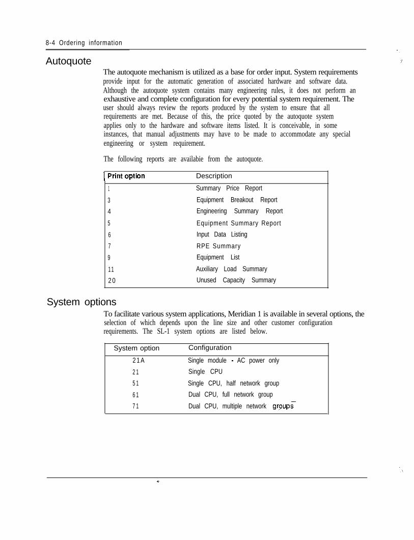
8-4 Ordering information
Autoquote ,i‘The autoquote mechanism is utilized as a base for order input. System requirementsprovide input for the automatic generation of associated hardware and software data.Although the autoquote system contains many engineering rules, it does not perform anexhaustive and complete configuration for every potential system requirement. Theuser should always review the reports produced by the system to ensure that allrequirements are met. Because of this, the price quoted by the autoquote systemapplies only to the hardware and software items listed. It is conceivable, in someinstances, that manual adjustments may have to be made to accommodate any specialengineering or system requirement.
The following reports are availabie from the autoquote.
mption Description
1
3
4
5
6
7
9
11
2 0
Summary Price Report
Equipment Breakout Report
Engineering Summary Report
Equipment Summary Report
Input Data Listing
RPE Summary
Equipment List
Auxiliary Load Summary
Unused Capacity Summary
System optionsTo facilitate various system applications, Meridian 1 is available in several options, theselection of which depends upon the line size and other customer configurationrequirements. The SL-1 system options are listed below.
System option Configuration
2 1 A Single module - AC power only
2 1 Single CPU
5 1 Single CPU, half network group
6 1 Dual CPU, full network group
7 1 Dual CPU, multiple network grpups
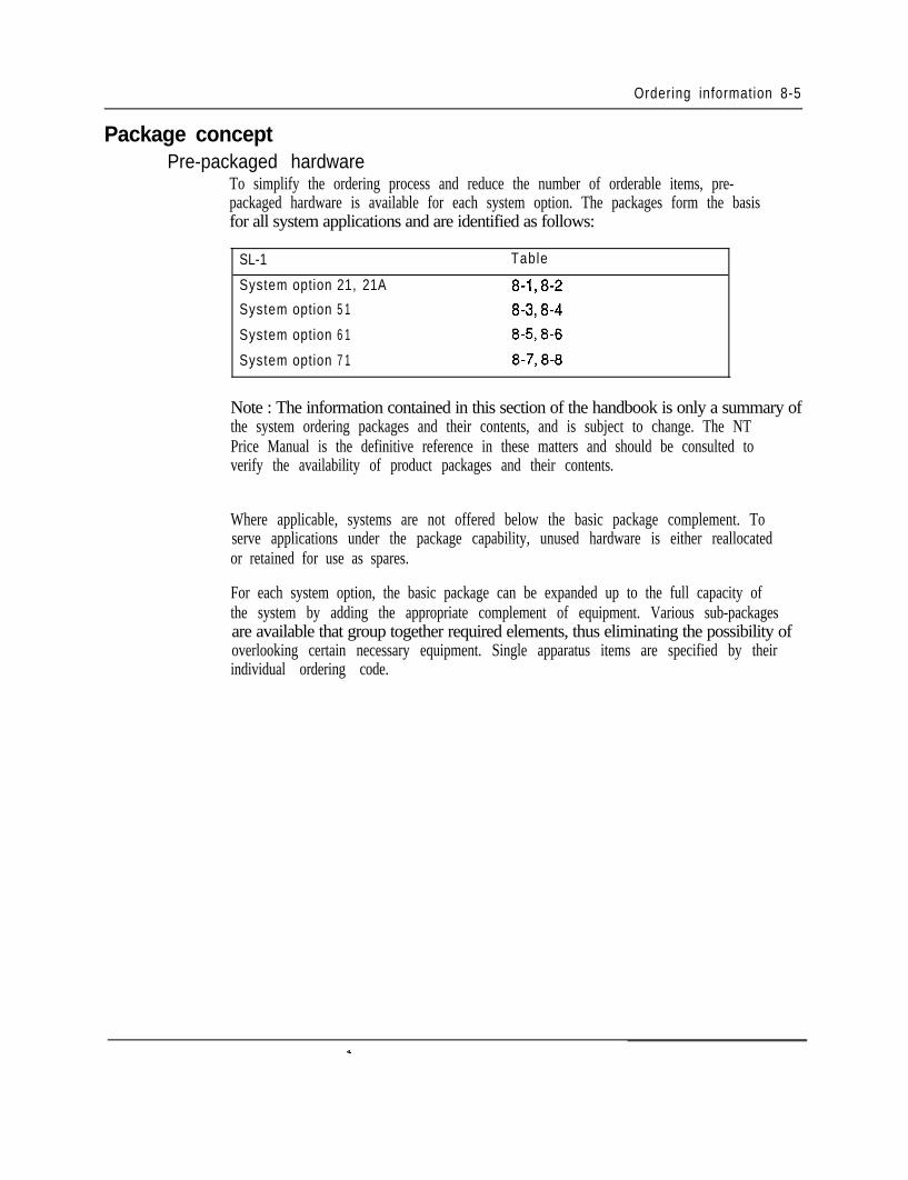
Ordering information 8-5
Package conceptPre-packaged hardware
To simplify the ordering process and reduce the number of orderable items, pre-packaged hardware is available for each system option. The packages form the basisfor all system applications and are identified as follows:
SL-1 Table
System option 21, 21A 8-1,8-2
System option 5 1 8-3,8-4
System option 6 1 8-58-6
System option 7 1 8-7,8-8
Note : The information contained in this section of the handbook is only a summary ofthe system ordering packages and their contents, and is subject to change. The NTPrice Manual is the definitive reference in these matters and should be consulted toverify the availability of product packages and their contents.
Where applicable, systems are not offered below the basic package complement. Toserve applications under the package capability, unused hardware is either reallocatedor retained for use as spares.
For each system option, the basic package can be expanded up to the full capacity ofthe system by adding the appropriate complement of equipment. Various sub-packagesare available that group together required elements, thus eliminating the possibility ofoverlooking certain necessary equipment. Single apparatus items are specified by theirindividual ordering code.

8-6 Ordering information
SL-1 system option 21,21AFor small business applications, system option 21 is available in two configurations foreither AC or DC power arrangements as outlined in Table 8-l. Another version,system option 21A (order code SY 1006A), which is a single-module system configuredfor AC-only power arrangement, is also available to address applications up to 160ports. Table 8-2 provides a breakdown of the hardware contained.in each of the systempackages.
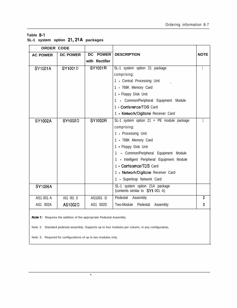
Ordering information 8-7
Table 8-ISL-1 system option 21,21A packages
ORDER CODE
AC POWER DC POWER DC POWER DESCRIPTION
with Rectifier
SYlOOlA SYlOOl D SYlOOl R SL-1 system option 21 package
comprising:
NOTE
1
1 - Central Processing Unit
1 - 768K Memory Card
1 - Floppy Disk Unit
1 - Common/Peripheral Equipment Module
1 - ConferenceflDS Card
SY1002A SY1002D
1 - Network/Digitone Receiver Card
SY1002R SL-1 system option 21 + PE module package 1
comprising:
1 - Processing Unit
1 - 768K Memory Card
1 - Floppy Disk Unit
1 - Common/Peripheral Equipment Module
1 - Intelligent Peripheral Equipment Module
1 - Conference/TDS Card
1 - Network/Digitone Receiver Card
1 - Superloop Network Card
SY1006A SL-1 system option 21A package(contents similar to SYl 001 A)
AS1 001 A AS1 001 D AS1001 D Pedestal Assembly
AS1 002A AS1002D AS1 002D Two-Module Pedestal Assembly
Noie 7: Requires the addition of the appropriate Pedestal Assembly.
Note 2: Standard pedestal assembly. Supports up to four modules per column, in any configuration.- -
Note 3: Required for configurations of up to two modules only.
2
3
*.
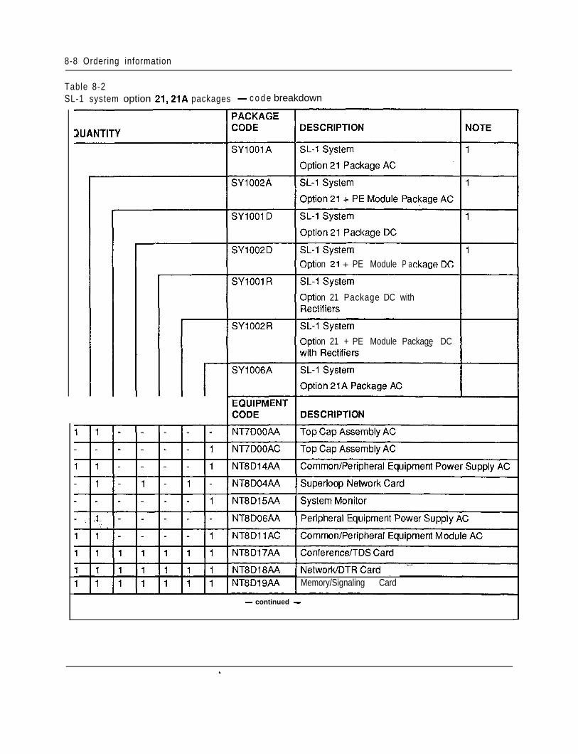
8-8 Ordering information
Table 8-2SL-1 system option 21,21A packages - c o d e breakdown
ZIUANTITY
tion 21+ PE Module P a
tion 21 Package DC with
tion 21 + PE Module Package DC
I I I I I I I IMemory/Signaling Card
- continued -
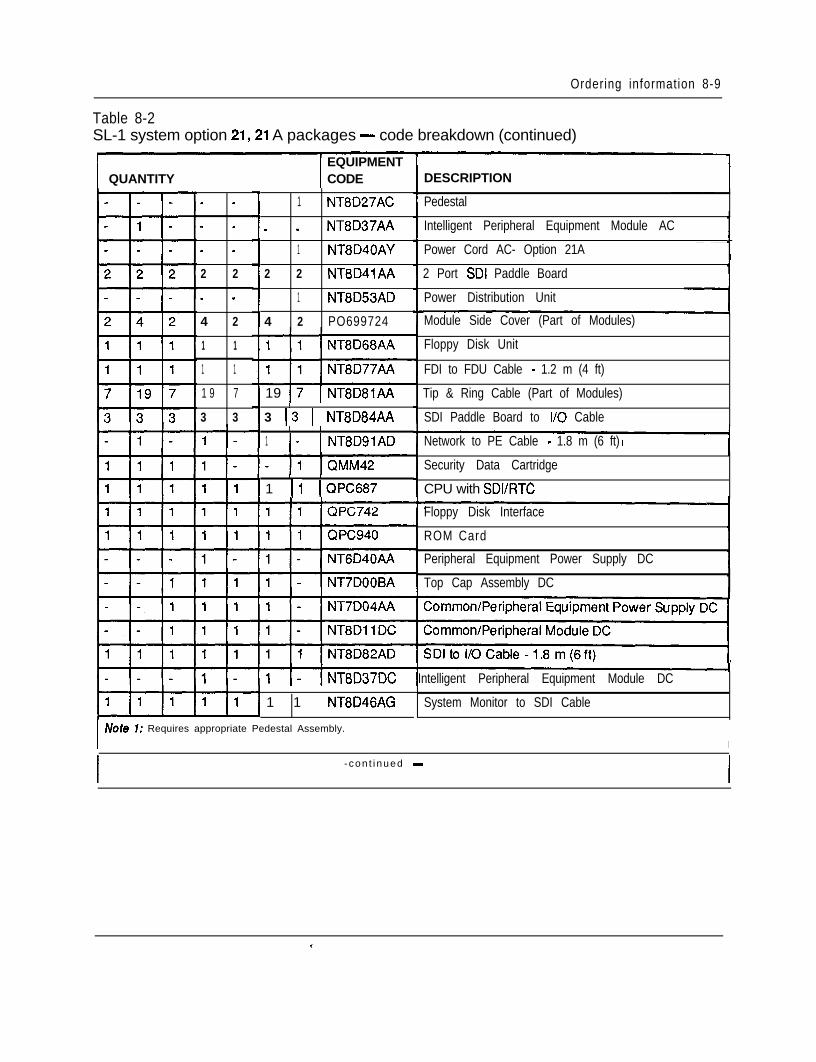
Ordering information 8-9
Table 8-2SL-1 system option 21,21 A packages - code breakdown (continued)
I I EQUIPMENTQUANTITY CODE
- -
- -
- -
2 2
- -
4 2
1 1
1 1
1 9 7
3 3
1 NT8D27AC
- - NT8D37AA
1 NT8D40AY
2 2 NT8D41AA
1 NT8D53AD
4 2 PO699724
19 17 1 NT8D81AAI
3 13 1 NT8D84AAI I
1 I- 1 NT8DSlAD
I I
1 11 (QPC687
DESCRIPTION
I Note 7: Requires appropriate Pedestal Assembly.
I
1 1 NT8D46AG
Pedestal
Intelligent Peripheral Equipment Module AC1
Power Cord AC- Option 21A -12 Port SDI Paddle Board
Power Distribution Unit
Module Side Cover (Part of Modules)
Floppy Disk Unit
FDI to FDU Cable - 1.2 m (4 ft)
Tip & Ring Cable (Part of Modules)
SDI Paddle Board to I/O Cable
Network to PE Cable - 1.8 m (6 ft)
Security Data Cartridge
CPU with SDVRTC
Floppy Disk Interface
ROM Card
Peripheral Equipment Power Supply DC
Top Cap Assembly DC
Common/Peripheral Equipment Power Supply DC11Intelligent Peripheral Equipment Module DC
System Monitor to SDI Cable
- con t i nued -
c
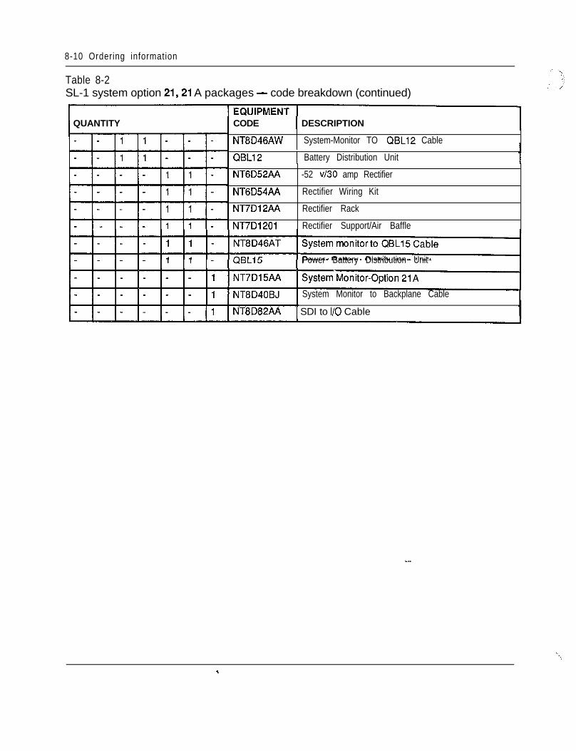
8-10 Ordering information
Table 8-2SL-1 system option 21,21 A packages - code breakdown (continued)
QUANTITY CODE I DESCRIPTIONI
NT8D46AW 1 System-Monitor TO QBL12 Cable
QBL12I
1 Battery Distribution Unit
NT6D52AA
NT6D54AA
NT7D12AA
NT7D1201
-52 v/30 amp Rectifier
Rectifier Wiring Kit
Rectifier Rack
Rectifier Support/Air Baffle
Power Battery Distribution Unit
System Monitor to Backplane Cable
NT8D82AA 1 SDI to I/O Cable
‘\,
*.
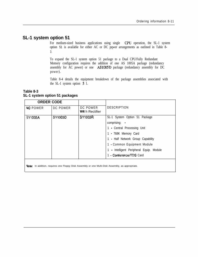
Ordering information 8-11
SL-1 system option 51For medium-sized business applications using single CPU operation, the SL-1 systemoption 51 is available for either AC or DC pqwer arrangements as outlined in Table 8-3.
To expand the SL-1 system option 51 package to a Dual CPU/Fully RedundantMemory configuration requires the addition of one AS 1005A package (redundancyassembly for AC power) or one ASlOOSD package (redundancy assembly for DCpower).
Table 8-4 details the equipment breakdown of the package assemblies associated withthe SL-1 system option 5 1.
Table 8-3SL-1 system option 51 packages
ORDER CODE4C POWER DC POWER DC POWER DESCRIPTION
Wtt h Rectifier
SYlOQ3A SY1003D SY1003R SL-1 System Option 51 Package
comprising: -
1 - Central Processing Unit
1 - 768K Memory Card
1 - Half Network Group Capability
1 - Common Equipment Module
1 - Intelligent Peripheral Equip. Module
1 - ConferenceflDS Card
Mote: In addition, requires one Floppy Disk Assembly or one Multi-Disk Assembly, as appropriate.
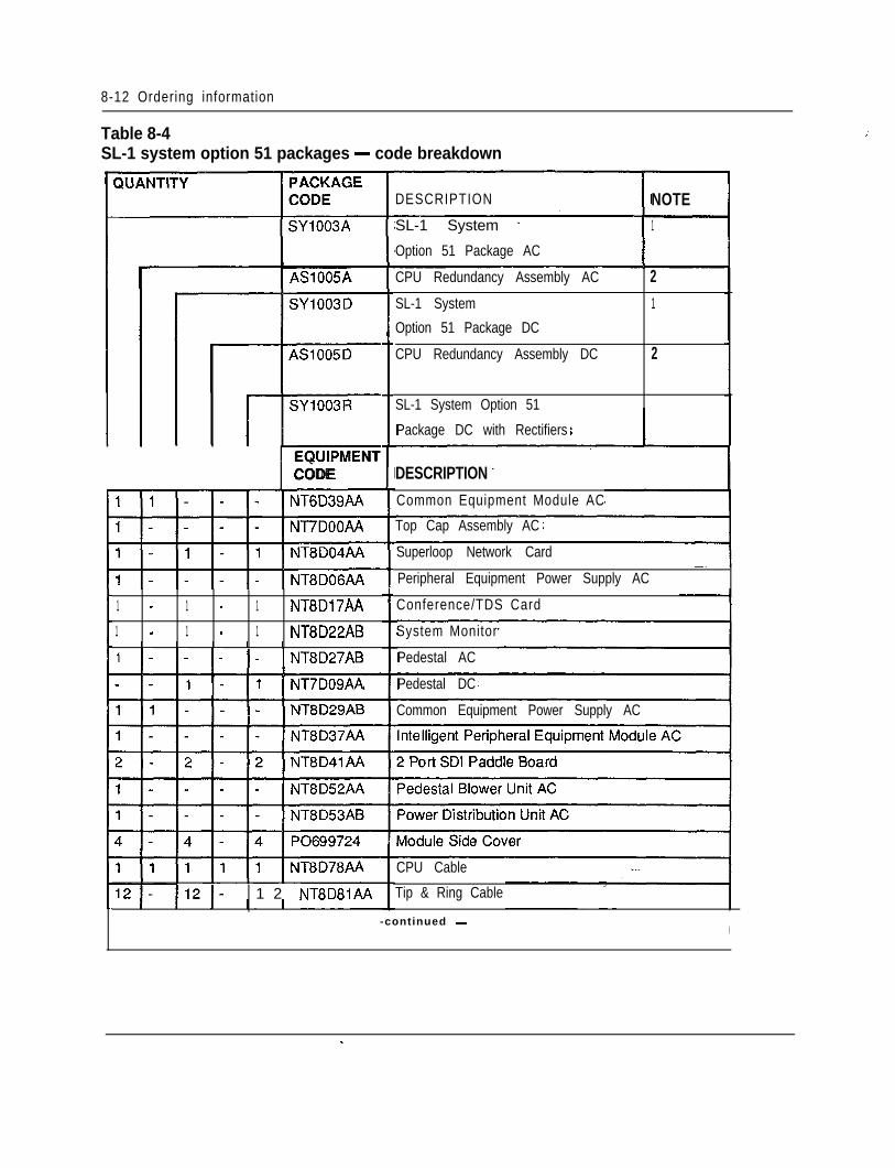
8-12 Ordering information
Table 8-4SL-1 system option 51 packages - code breakdown
/’
I
1 AS1005A
-r=-SY1003RItEQUIPMENTCODE
1 - 1 - 1 NT8D17AA
1 - 1 - 1 NT8D22ABI I I I I
1 I- I- I- I- 1 NT8D27AB
- I- I- 11 1 NT7DOSAA
I
1 2 NT8D81AA
DESCRIPTION NOTE ISL-1 System - 1
Option 51 Package AC .I ICPU Redundancy Assembly AC 2SL-1 System 1
Option 51 Package DC
CPU Redundancy Assembly DC 2
SL-1 System Option 51
Package DC with Rectifiers
DESCRIPTIONCommon Equipment Module AC
Top Cap Assembly AC
Superloop Network Card
Peripheral Equipment Power Supply AC
Conference/TDS Card
System Monitor
Pedestal AC
Pedestal DC
Common Equipment Power Supply AC
CPU Cable
Tip & Ring Cable
-continued -I
. .
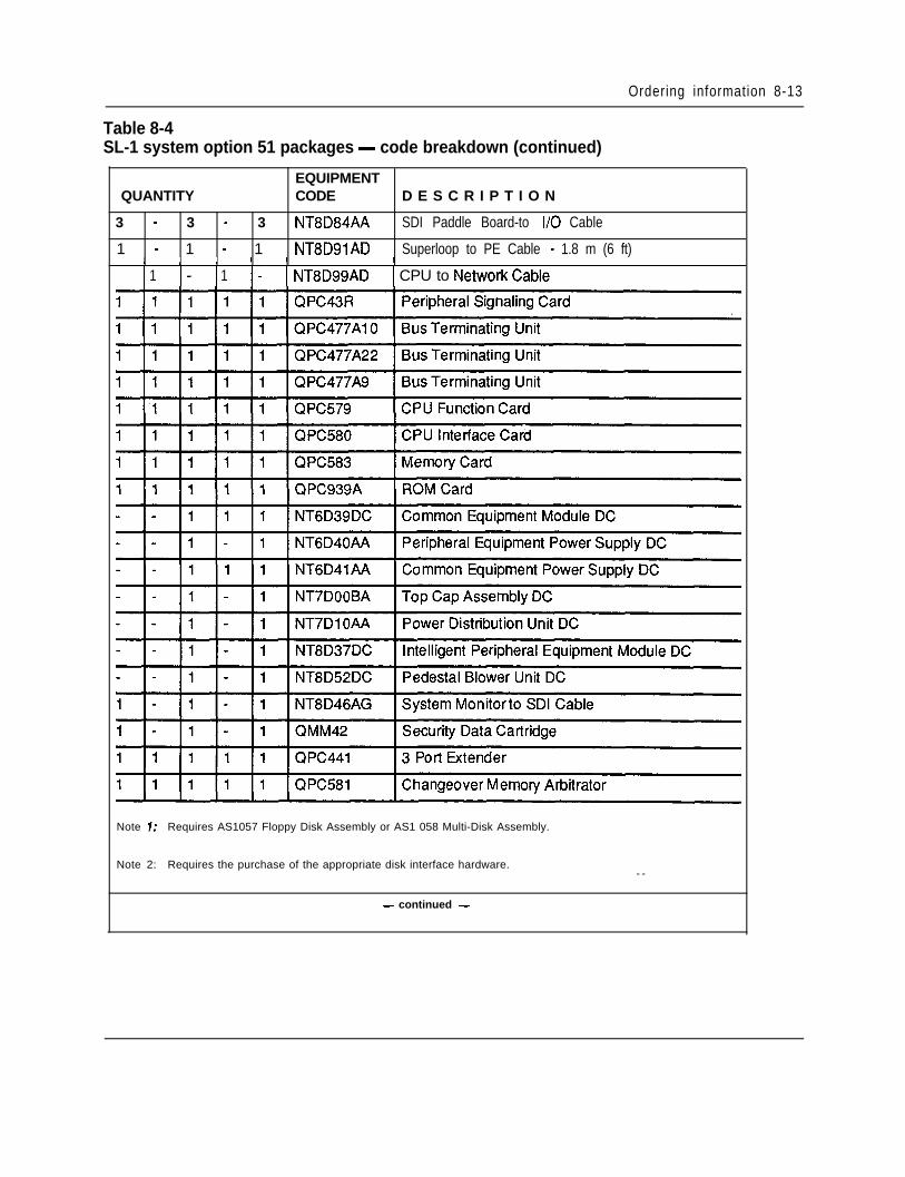
Ordering information 8-13
Table 8-4SL-1 system option 51 packages - code breakdown (continued)
EQUIPMENTQUANTITY CODE D E S C R I P T I O N
3 - 3 - 3 NT8D84AA SDI Paddle Board-to I/O Cable
1 - 1 - 1 NT8DSlAD Superloop to PE Cable - 1.8 m (6 ft)I I I I I I
1 1 I- 1 1 I- I NT8D99AD I CPU to NetworkCable
Note 7: Requires AS1057 Floppy Disk Assembly or AS1 058 Multi-Disk Assembly.
Note 2: Requires the purchase of the appropriate disk interface hardware.- -
- continued -
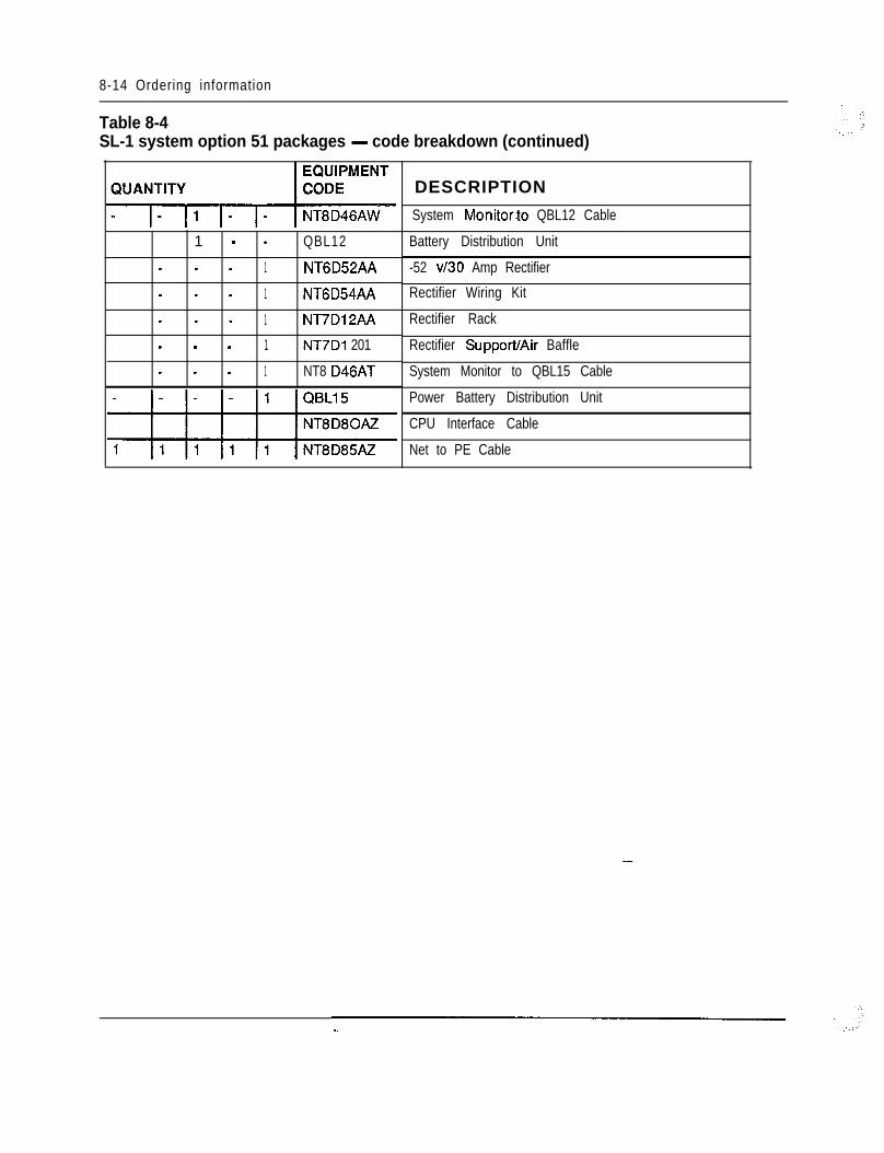
8-14 Ordering information
Table 8-4SL-1 system option 51 packages - code breakdown (continued)
1 - - QBL12- - - 1 NT6D52AA- - - 1 NT6D54AA- - - 1 NT7Dl2AA- - - 1 NT7Di 201- - - 1 NT8 D46AT
i DESCRIPTION
~ System Monitor.to QBL12 Cable
Battery Distribution Unit
-52 v/30 Amp Rectifier
Rectifier Wiring Kit
Rectifier Rack
Rectifier Support/Air Baffle
System Monitor to QBL15 Cable
Power Battery Distribution Unit
CPU Interface Cable
Net to PE Cable
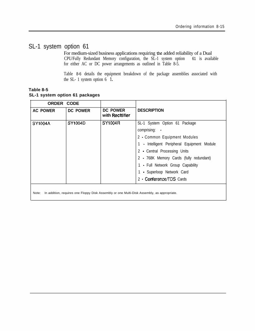
Ordering information 8-15
SL-1 system option 61For medium-sized business applications requiring ,tie added reliability of a DualCPU/Fully Redundant Memory configuration, the SL-1 system option 61 is availablefor either AC or DC power arrangements as outlined in Table 8-5.
Table 8-5
Table 8-6 details the equipment breakdown of the package assemblies associated withthe SL- 1 system option 6 1.
SL-1 system option 61 packages
ORDER CODE
AC POWER DC POWER DC POWER DESCRIPTIONwith Recftifier
SY1004A SY1004D SY1004R SL-1 System Option 61 Package
comprising: -
2 - Common Equipment Modules
1 - Intelligent Peripheral Equipment Module
2 - Central Processing Units
2 - 768K Memory Cards (fully redundant)
1 - Full Network Group Capability
1 - Superloop Network Card
2 - Conference/TDS Cards
Note: In addition, requires one Floppy Disk Assembly or one Multi-Disk Assembly, as appropriate.
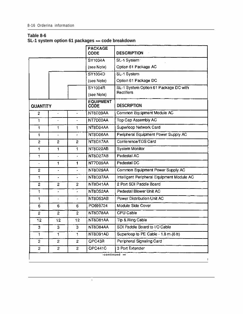
8-16 Orderina information
Table 8-6SL-1 system option 61 packages - code breakdown
DESCRIPTION
I -continued -
I
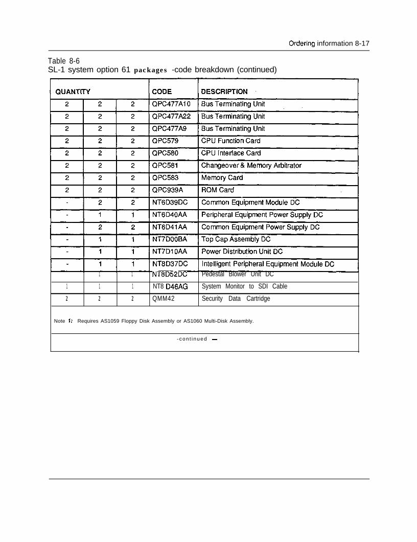
Ordering information 8-17
Table 8-6SL-1 system option 61 packages -code breakdown (continued)
1 1 NT8D52DC Pedestal Blower Unit DC
1 1 1 NT8 D46AG System Monitor to SDI Cable
2 2 2 QMM42 Security Data Cartridge
Note 7: Requires AS1059 Floppy Disk Assembly or AS1060 Multi-Disk Assembly.
- con t i nued -
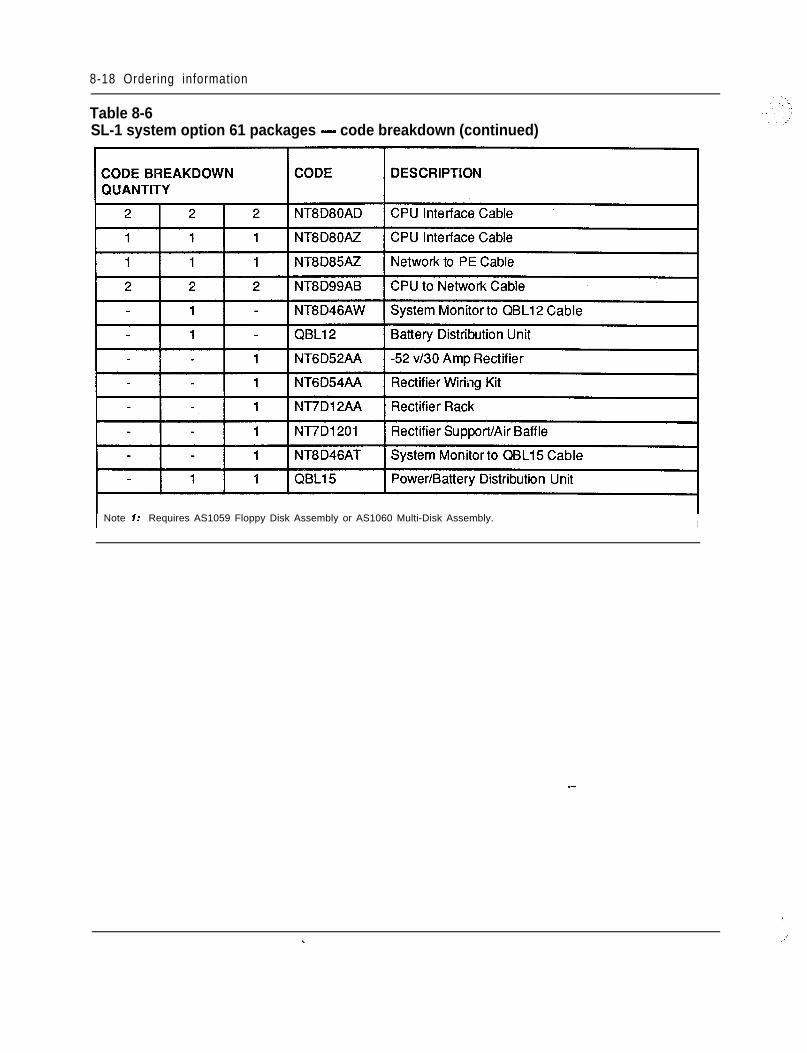
8-18 Ordering information
Table 8-6SL-1 system option 61 packages - code breakdown (continued)
I Note 7: Requires AS1059 Floppy Disk Assembly or AS1060 Multi-Disk Assembly. I
--
-
v. .,,’
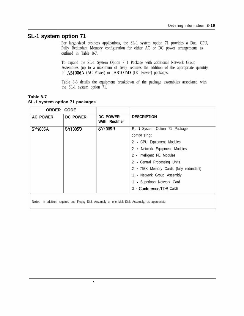
Ordering information 8-19
SL-1 system option 71For large-sized business applications, the SL-1 system option 71 provides a Dual CPU,Fully Redundant Memory configuration for either AC or DC power arrangements asoutlined in Table 8-7.
To expand the SL-1 System Option 7 1 Package with additional Network GroupAssemblies (up to a maximum of five), requires the addition of the appropriate quantityof AS1006A (AC Power) or AS1006D (DC Power) packages.
Table 8-8 details the equipment breakdown of the package assemblies associated withthe SL-1 system option 71.
Table 8-7SL-1 system option 71 packages
ORDER CODE
AC POWER DC POWER DC POWER DESCRIPTIONWith Rectifier
SY1005A SYlOOSD SY1005R X-1 System Option 71 Package
comprising:
2 - CPU Equipment Modules
2 - Network Equipment Modules
2 - Intelligent PE Modules
2 - Central Processing Units
2 - 768K Memory Cards (fully redundant)
1 - Network Group Assembly
1 - Superloop Network Card
2 - Conference/TDS Cards
Note : In addition, requires one Floppy Disk Assembly or one Multi-Disk Assembly, as appropriate.
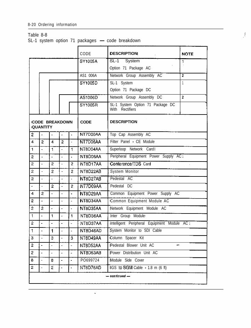
8-20 Ordering information
Table 8-8SL-1 system option 71 packages - code breakdown
j,
DESCRIPTIONCODE
SY1005A SL-1 System -
Option 71 Package AC
Network Group Assembly AC 2
SL-1 System 1
Option 71 Package DC
Network Group Assembly DC 2
SL-1 System Option 71 Package DCWith Rectifiers
AS1 006A
SY1005D
CODE BREAKDOWNQUANTITY
CODE DESCRIPTION
NT7DOOAA Top Cap Assembly AC
Filter Panel - CE ModuleNT7DOGAA
NT8D04AA
NT8DOGAA
Superloop Network Card
Peripheral Equipment Power Supply AC
Conference/TDS CardNT8D17AA
NT8D22AB
NT8D27AB
System Monitor
Pedestal AC
NT-/DOS/VI
NT8D29AA
NT8D34AA
Pedestal DC
Common Equipment Power Supply AC
Common Equipment Module AC
Network Equipment Module ACNT8D35AA
NT8D36AA
NT8D37AA
Inter Group Module
Intelligent Peripheral Equipment Module AC
System Monitor to SDI Cable
Column Spacer Kit
Pedestal Blower Unit AC -
Power Distribution Unit AC
Module Side Cover
IGS toSGM Cable - 1.8 m (6 ft)
NT8D46AD
NT8D49AA
NT8D52AA
NT8D53AB
PO699724
NT8D76AD
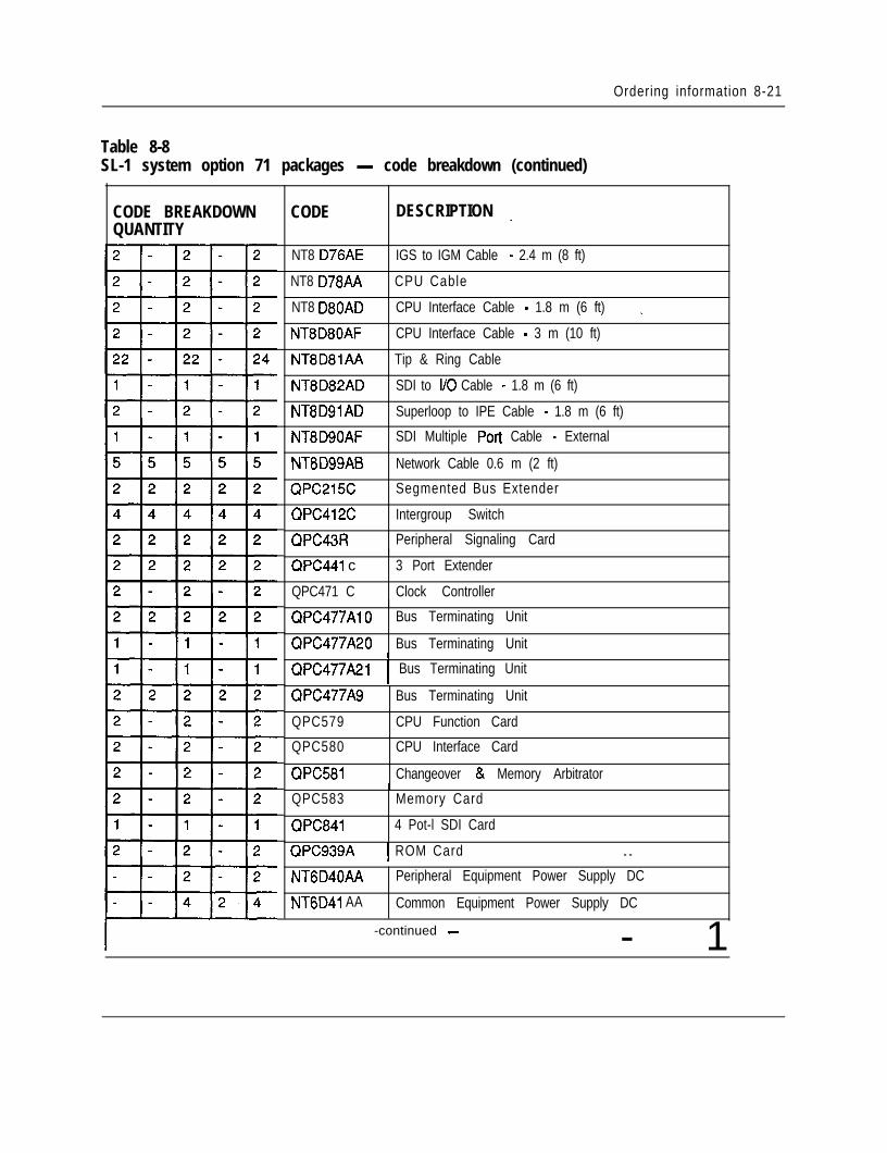
Ordering information 8-21
Table 8-8SL-1 system option 71 packages - code breakdown (continued)
CODE BREAKDOWNQUANTITY
CODE DESCRIPTION _
NT8 D76AE IGS to IGM Cable - 2.4 m (8 ft)
NT8 D78AA
NT8 D80AD
NT8D80AF
CPU Cable
CPU Interface Cable - 1.8 m (6 ft)
CPU Interface Cable - 3 m (10 ft)
_
NT8D8lAA Tip & Ring Cable
NT8D82AD SDI to I/O Cable - 1.8 m (6 ft)
NT8DSlAD Superloop to IPE Cable - 1.8 m (6 ft)
NT8D90AF SDI Multiple Port Cable - External
NT8D99AB Network Cable 0.6 m (2 ft)
QPC215C Segmented Bus Extender
QPC412C
QPC43R
Intergroup Switch
Peripheral Signaling Card
QPC441 c
QPC471 C
3 Port Extender
Clock Controller
QPC477AlO Bus Terminating Unit
QPC477A20 Bus Terminating UnitI
QPC477A21 1 Bus Terminating UnitI
QPC477A9 Bus Terminating Unit
QPC579 CPU Function Card
QPC580 CPU Interface Card
QPC581 Changeover & Memory Arbitrator
QPC583
QPC841
Memory Card
4 Pot-l SDI Card
QPC939A 1 ROM Card - -NT6D40AA
NT6D41 AA
Peripheral Equipment Power Supply DC
Common Equipment Power Supply DC
-continued - - 1
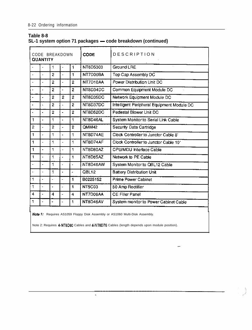
8-22 Ordering information
Table 8-8SL-1 system option 71 packages - code breakdown (continued)
CODE BREAKDOWN D E S C R I P T I O N
Note 7: Requires AS1059 Floppy Disk Assembly or AS1060 Multi-Disk Assembly.
Note 2: Requires 4-NT8D80 Cables and 4-NT8D76 Cables (length depends upon module position).
--
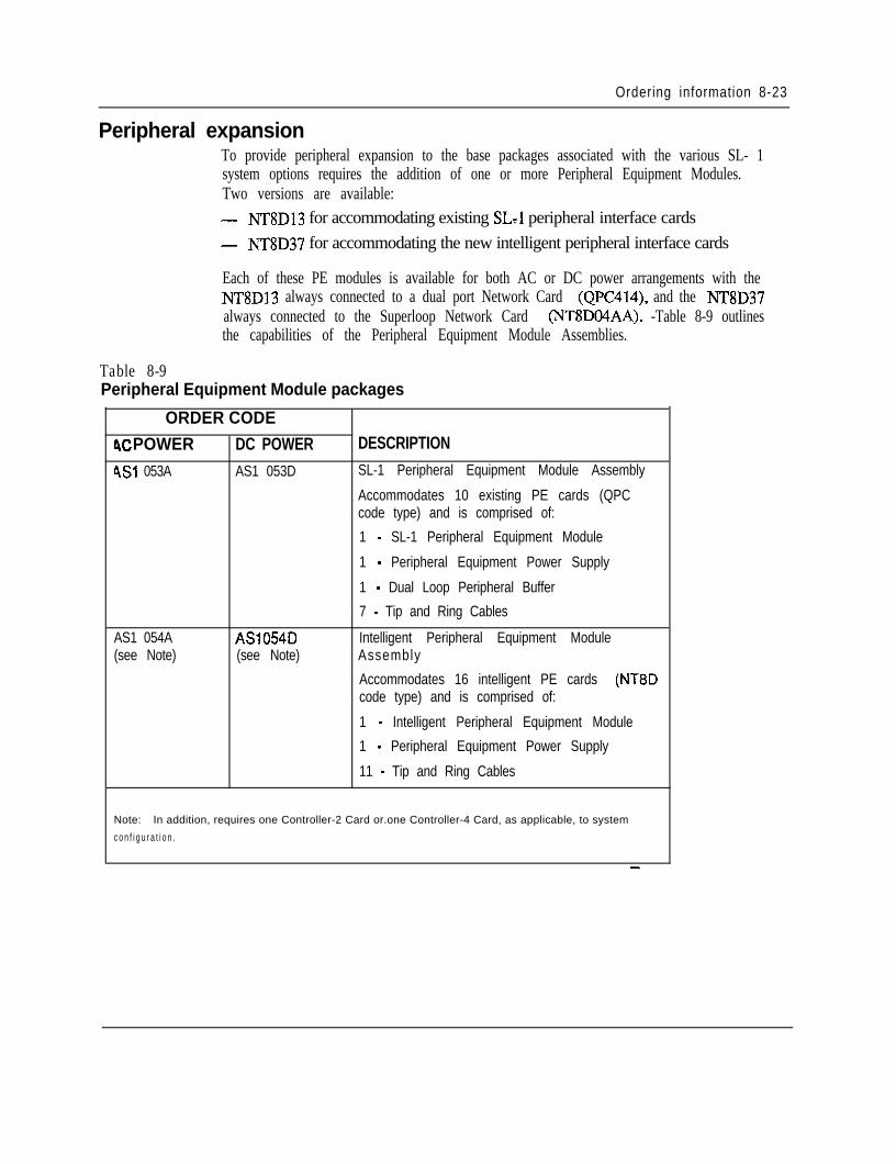
Ordering information 8-23
Peripheral expansionTo provide peripheral expansion to the base packages associated with the various SL- 1system options requires the addition of one or more Peripheral Equipment Modules.Two versions are available:- NT8D13 for accommodating existing SL-1 peripheral interface cards- NT8D37 for accommodating the new intelligent peripheral interface cards
Each of these PE modules is available for both AC or DC power arrangements with theNT8D13 always connected to a dual port Network Card (QPC414), and the NT8D37always connected to the Superloop Network Card (NT8DO4AA). -Table 8-9 outlinesthe capabilities of the Peripheral Equipment Module Assemblies.
Table 8-9Peripheral Equipment Module packages
ORDER CODEIX POWER DC POWERAS1 053A AS1 053D
AS1 054A AS1054D(see Note) (see Note)
DESCRIPTIONSL-1 Peripheral Equipment Module Assembly
Accommodates 10 existing PE cards (QPCcode type) and is comprised of:
1 - SL-1 Peripheral Equipment Module
1 - Peripheral Equipment Power Supply
1 - Dual Loop Peripheral Buffer
7 - Tip and Ring Cables
Intelligent Peripheral Equipment ModuleAssembly
Accommodates 16 intelligent PE cards (NT8Dcode type) and is comprised of:
1 - Intelligent Peripheral Equipment Module
1 - Peripheral Equipment Power Supply
11 - Tip and Ring Cables
Note: In addition, requires one Controller-2 Card or.one Controller-4 Card, as applicable, to system
c o n f i g u r a t i o n .
_-
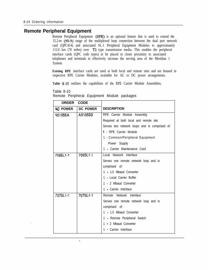
8-24 Ordering information
Remote Peripheral EquipmentRemote Peripheral Equipment (RPE) is an optional feature that is used to extend the15.2-m (50-ft) range of the multiplexed loop connection between the dual port networkcard (QPC414) and associated SL-1 Peripheral Equipment Modules to approximately112.6 km (70 miles) over Tl type transmission media. This enables the peripheralinterface cards (QPC code types) to be placed in closer proximity to associatedtelephones and terminals to effectively increase the serving area of the Meridian 1System.
Existing RPE interface cards are used at both local and remote sites and are housed inrespective RPE Carrier Modules, available for AC or DC power arrangements.
Table S-10 outlines the capabilities of the RPE Carrier Module Assemblies.
Table 8-10Remote Peripheral Equipment Module packages
ORDER CODE
4C POWER DC POWER DESCRIPTION
4Sl Q55A AS1055D RPE Carrier Module Assembly
Required at both local and remote site
Serves two network loops and is comprised of:
1 - RPE Carrier Module
1 - Common/Peripheral Equipment
Power Supply
706SLl-1 706SLi -1
1 - Carrier Maintenance Card
Local Network Interface
Serves one remote network loop and is
comprised of:
707SLl-1 707SLl-1
1 - 1.5 Mbaud Converter
1 - Local Carrier Buffer
1 - 2 Mbaud Converter
1 - Carrier Interface
Remote Network Interface
Serves one remote network loop and is
comprised of:
1 - 1.5 Mbaud Converter
1 - Remote Peripheral Switch
1 - 2 Mbaud Converter
1 - Carrier Interface
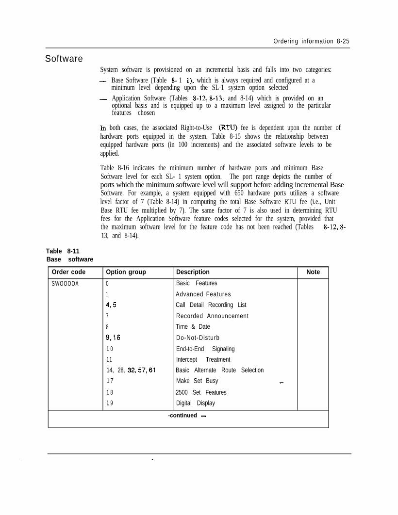
Ordering information 8-25
SoftwareSystem software is provisioned on an incremental basis and falls into two categories:- Base Software (Table 8- 1 l), which is always required and configured at a
minimum level depending upon the SL-1 system option selected- Application Software (Tables 8-12,8-13; and 8-14) which is provided on an
optional basis and is equipped up to a maximum level assigned to the particularfeatures chosen
In both cases, the associated Right-to-Use (RTU) fee is dependent upon the number ofhardware ports equipped in the system. Table 8-15 shows the relationship betweenequipped hardware ports (in 100 increments) and the associated software levels to beapplied.
Table 8-16 indicates the minimum number of hardware ports and minimum BaseSoftware level for each SL- 1 system option. The port range depicts the number ofports which the minimum software level will support before adding incremental BaseSoftware. For example, a system equipped with 650 hardware ports utilizes a softwarelevel factor of 7 (Table 8-14) in computing the total Base Software RTU fee (i.e., UnitBase RTU fee multiplied by 7). The same factor of 7 is also used in determining RTUfees for the Application Software feature codes selected for the system, provided thatthe maximum software level for the feature code has not been reached (Tables 8-12,8-13, and 8-14).
Table 8-11Base software
Order code
SWOOOOA
Option group Description Note
0 Basic Features
1 Advanced Features
495 Call Detail Recording List
7 Recorded Announcement
8 Time & Date
9,16 Do-Not-Disturb
1 0 End-to-End Signaling
11 Intercept Treatment
14, 28, 32,57,61 Basic Alternate Route Selection
1 7 Make Set Busy -
1 8 2500 Set Features
1 9 Digital Display
-continued -
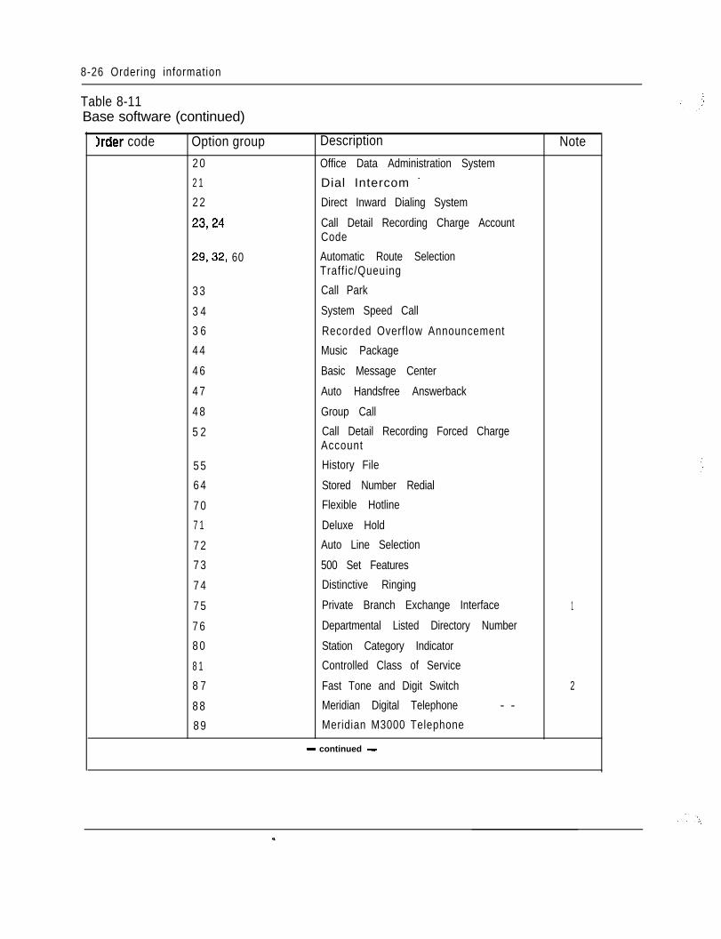
8-26 Ordering information
Table 8-11Base software (continued)
Irder code Option group2 0
2 1
2 2
23,24
29,32, 60
3 3
3 4
3 6
4 4
4 6
4 7
4 8
5 2
5 5
6 4
7 0
7 1
7 2
7 3
7 4
7 5
7 6
8 0
8 1
8 7
8 8
8 9
Description NoteOffice Data Administration System
Dial Intercom -
Direct Inward Dialing System
Call Detail Recording Charge AccountCode
Automatic Route SelectionTraff ic/Queuing
Call Park
System Speed Call
Recorded Overflow Announcement
Music Package
Basic Message Center
Auto Handsfree Answerback
Group Call
Call Detail Recording Forced ChargeAccount
History File
Stored Number Redial
Flexible Hotline
Deluxe Hold
Auto Line Selection
500 Set Features
Distinctive Ringing
Private Branch Exchange Interface 1
Departmental Listed Directory Number
Station Category Indicator
Controlled Class of Service
Fast Tone and Digit Switch 2
Meridian Digital Telephone - -
Meridian M3000 Telephone
- continued -
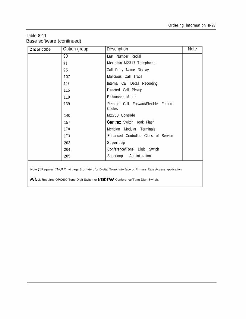
Ordering information 8-27
Table 8-11Base software (continued)
3rder code Option group Description Note9 0 Last Number Redial
9 1 Meridian M2317 Telephone
9 5 Call Party Name Display
107 Malicious Call Trace
1 0 8 Internal Call Detail Recording
115 Directed Call Pickup
119 Enhanced Music
139 Remote Call Forward/Flexible FeatureCodes
140 M2250 Console
157 Centrex Switch Hook Flash
1 7 0 Meridian Modular Terminals
1 7 3 Enhanced Controlled Class of Service
203 Superloop
204 Conference/Tone Digit Switch
205 Superloop Administration
Note 7: Requires QPC471, vintage B or later, for Digital Trunk Interface or Primary Rate Access application.
Note 2: Requires QPC609 Tone Digit Switch or NT8D17AA Conference/Tone Digit Switch.
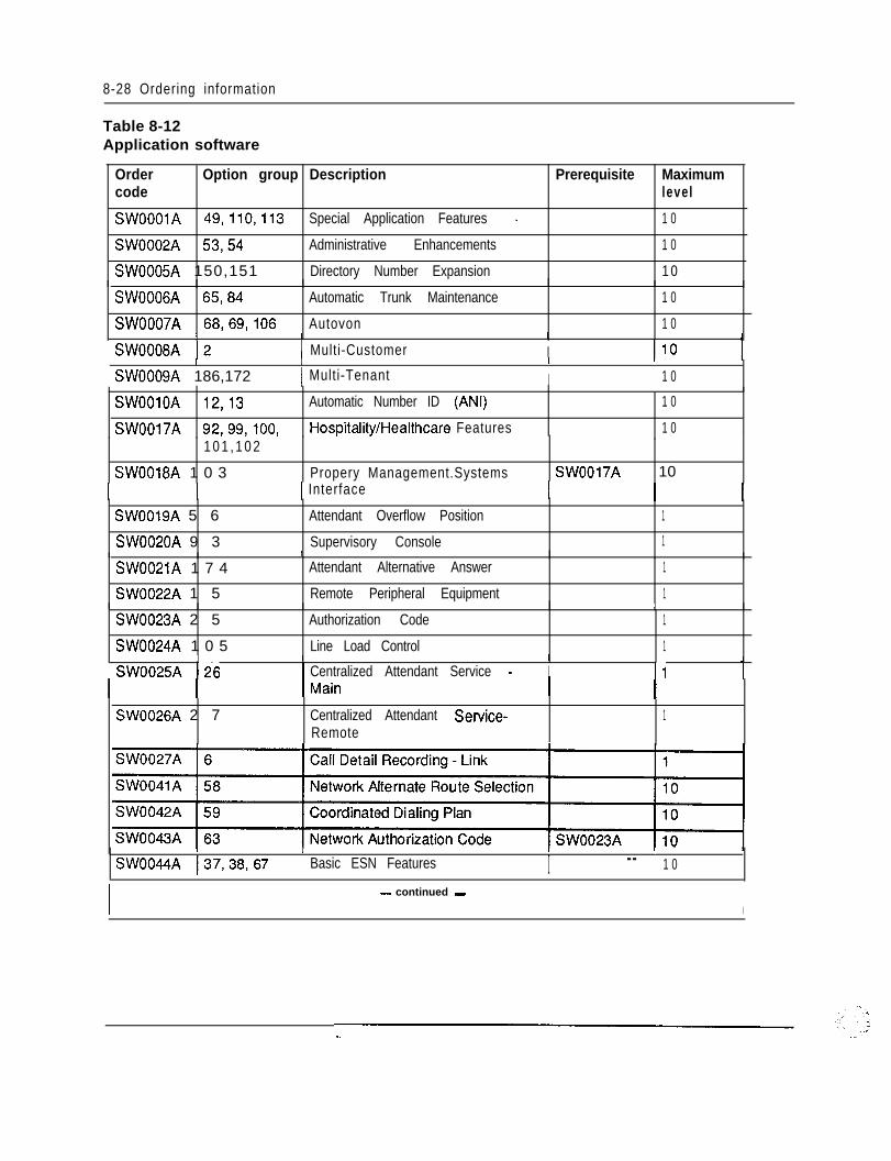
8-28 Ordering information
Table 8-12Application software
Order Option group Description Prerequisite Maximumcode level
SWOOOlA 49,110,113 Special Application Features - 1 0
SW0002A 53,54 Administrative Enhancements 1 0
SW0005A 150,151 Directory Number Expansion 1 0
SW0006A 65,84 Automatic Trunk Maintenance 1 0
SW0007A 68,69,106 Autovon 1 01
SW0008A 12I
1 Multi-CustomerI
I I10 1I I I I
SW0009A 186,172 1 Multi-Tenant I 1 0
SWOOlOA 12,13 Automatic Number ID (ANI) 1 0
SW0017A 92,99,100, Hospitality/Healthcare Features 1 01 0 1 , 1 0 2
SW0018A 1 0 3 Propery Management.Systems SW0017A 101 Interface
SW0019A 5 6 Attendant Overflow Position 1
SW0020A 9 3 Supervisory Console 1
SW0021A 1 7 4
SW0022A 1 5
I
Attendant Alternative Answer 1
Remote Peripheral Equipment 1
SW0023A 2 5 Authorization Code
SW0024A 1 0 5 Line Load Control
I
1
1I
SW0025A 126I I
Centralized Attendant Service - I 11 1
SW0026A 2 7 Centralized Attendant Service-Remote
1
I I I
SW0044A 137,38,67I
Basic ESN Features I - - 1 0
I - continued -
I
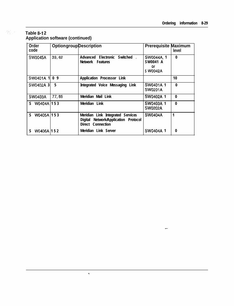
Ordering information 8-29
Table 8-l 2Application software (continued)
,Order Option group Description Prerequisite Maximumcode levelSW0045A 39,62 Advanced Electronic Switched - SW0044A, 1 0
Network Features SW0041 A
S W;;42A
SW0401A 1 0 9 Application Processor Link 10
SW0402A 3 5 Integrated Voice Messaging Link SW0401A 1 0SW0201A
SW0403A 77,85 Meridian Mail Link SW0402A 1 0
S W0404A 1 5 3 Meridian Link SW0403A 1 0SW0202A
S W0405A 1 5 3 Meridian Link Integrated Services SW0404A 1Digital Network/Application ProtocolDirect Connection
S W0406A 1 5 2 Meridian Link Server SW0404A 1 0
--
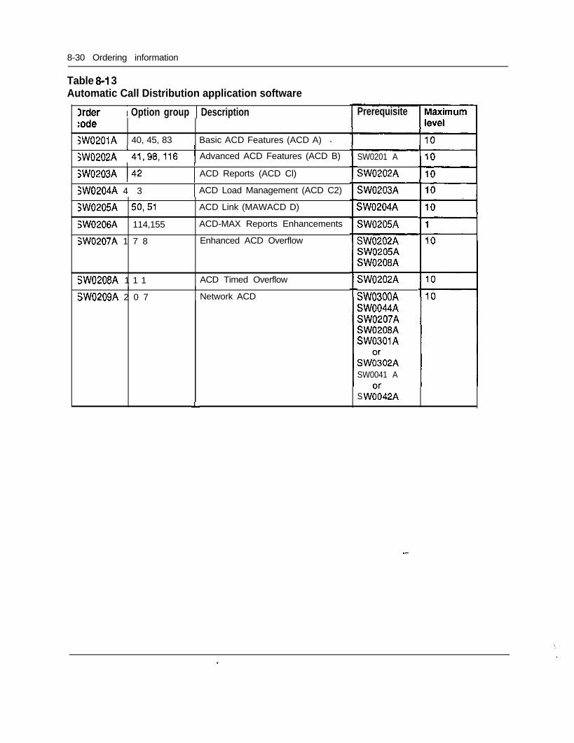
8-30 Ordering information
Table 8-I 3Automatic Call Distribution application software
Xder 1 Option group 1 Description:ode;W0201A 40, 45, 83 Basic ACD Features (ACD A) -
I I
jW0202A 41,98,116 1 Advanced ACD Features (ACD B)I
SW0203A I42I
SW0204A 4 3
SW0205A 50,51
SW0206A 114,155
SW0207A 1 7 8
SW0208A 1 1 1
SW0209A 2 0 7
I
1 ACD Reports (ACD Cl)I
1 ACD Load Management (ACD C2)
ACD Link (MAWACD D)
ACD-MAX Reports Enhancements
Enhanced ACD Overflow
ACD Timed Overflow
Network ACD
Prerequisite
SW0201 A
SW0202A
SW0203A
SW0204A
SW0205A
SW0202ASW0205ASW0208A
SW0202A
SW0300ASW0044ASW0207ASW0208ASW0301A
SW;;02ASW0041 A
S W;;42AL
--
‘,
/*.
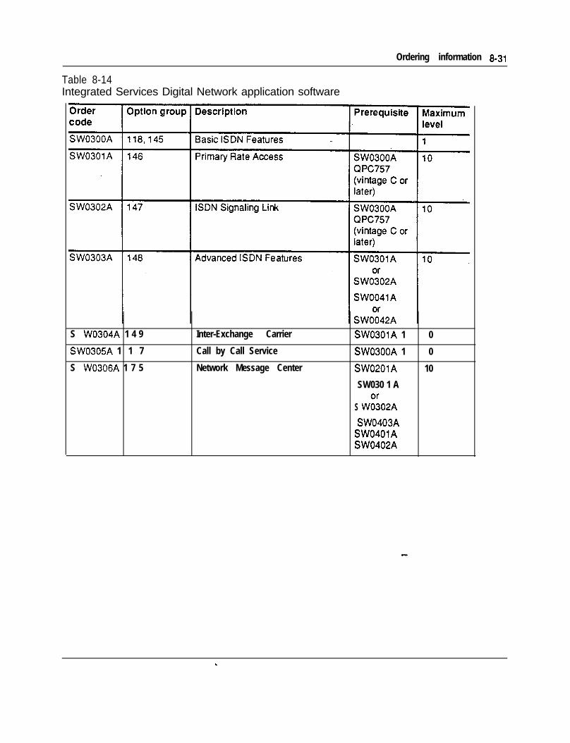
Table 8-14Integrated Services Digital Network application software
Ordering information 8.31
S W0304A 1 4 9 Inter-Exchange Carrier
SW0305A 1 1 7 Call by Call Service
S W0306A 1 7 5 Network Message Center
SW0301A 1 0
SW0300A 1 0
SW0201A 10
SW030 1 A
S W;;02A
SW0403ASW0401ASW0402A
--
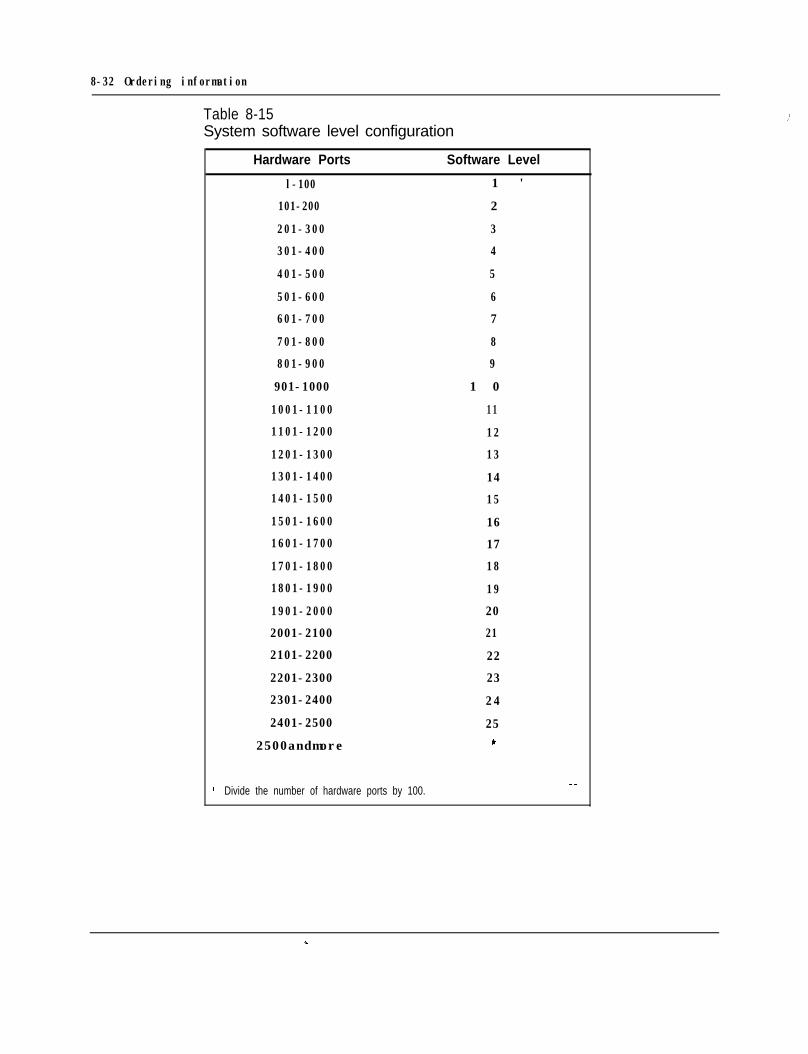
8-32 Ordering information
Table 8-15 II’System software level configuration
Hardware Ports Software Level
l-100 1 '
101-200 2
201-300 3
301-400 4
401-500 5
501-600 6
601-700 7
701-800 8
801-900 9
901-1000 1 0
1001-1100 11
1101-1200 12
1201-1300 13
1301-1400 14
1401-1500 15
1501-1600 16
1601-1700 17
1701-1800 18
1801-1900 19
1901-2000 20
2001-2100 21
2101-2200 22
2201-2300 23
2301-2400 24
2401-2500 25
2500andmore *
’ Divide the number of hardware ports by 100. --
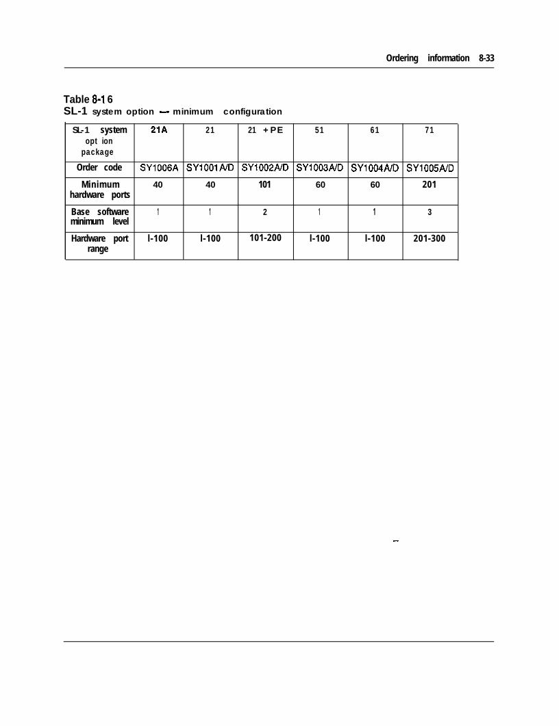
Ordering information 8-33
Table 8-l 6SL-1 system option - minimum configuration
SL-1 system 21A 21 21 + P E 51 61 71opt ion
package
Order code SY1006A SYlOOlA/D SY1002ND SY1003A/D SY1004A/D SY1005A/D
Minimum 40 40 101 60 60 201hardware ports
Base software 1 1 2 1 1 3minimum level
Hardware port l-100 l-100 101-200 l-100 l-100 201-300range
--
8-34 Ordering information
Meridian Modular Telephones :’The following Meridian Modular Telephones are available:- M2006-a single line telephone with 6 programmable keys- M2008--a multi-line set with 8 programmable keys- M2616-a high performance multi-line set with 16 programmable keys and
integrated Handsfree unit- M2016S-a Telephone Security Group Class II approved telephone designed to
provide on-hook security. It is similar to the M2616, with 16 programmable keys,but has no handsfree capability.
- M2216ACD-1-a multi-line set for ACD operations. It has 15 programmablefunction keys, a special ACD Display Module and twoRJ-32 jacks for modular electret headsets
- M2216ACD-2-a multi-line set for ACD operations. It has 15 programmablefunction keys, and a special ACD Display. It is similar to model 1, but with onePJ-327 jack for a carbon agent headset and one RJ-32 jack for an electretsupervisor headset
The following hardware options can be add on to Meridian Modular Telephones:- External Alerter Interface Board- Display Module- Programmable Data Adapter- Key Expansion Module
Table 8-17 lists the ordering codes for the Meridian Modular Telephones, alone andwith hardware options installed.
Table 8-l 8 lists the hardware options that can be purchased separately, and Table8-19 lists miscellaneous items.
Refer to Meridian Modular Telephones-Description and specification (553-2201-116) for additional information.
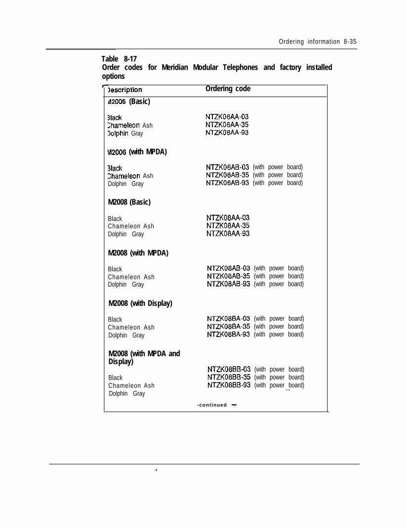
Ordering information 8-35
Table 8-17Order codes for Meridian Modular Telephones and factory installedoptionsr
Iescription Ordering code
~42006 (Basic)
3lack NTZKOGAA-032hameleon Ash NTZK06AA-35Dolphin Gray NTZK06AA-93
W2006 (with MPDA)
3lackzhameleon AshDolphin Gray
NTZKOGAB-03 (with power board)NTZK06AB-35 (with power board)NTZK06AB-93 (with power board)
M2008 (Basic)
BlackChameleon AshDolphin Gray
M2008 (with MPDA)
BlackChameleon AshDolphin Gray
M2008 (with Display)
BlackChameleon AshDolphin Gray
M2008 (with MPDA andDisplay)
BlackChameleon AshDolphin Gray
NTZK08AA-03NTZK08AA-35NTZK08AA-93
NTZK08AB-03 (with power board)NTZK08AB-35 (with power board)NTZK08AB-93 (with power board)
NTZK08BA-03 (with power board)NTZK08BA-35 (with power board)NTZK08BA-93 (with power board)
NTZK08BB-03 (with power board)NTZK08BB-35 (with power board)NTZK08BB-93 (with power board)
- -
-continued -
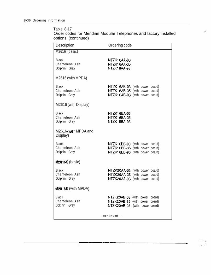
8-36 Ordering information
Table 8-17Order codes for Meridian Modular Telephones and factory installedoptions (continued)
DescriptionM2616 (basic)
Ordering code
BlackChameleon AshDolphin Gray
M2616 (with MPDA)
NTZK16AA-03NTZKl6AA-35NTZK16AA-93
BlackChameleon AshDolphin Gray
M2616 (with Display)
NTZK16AB-03 (with power board)NTZK16AB-35 (with power board)NTZK16AB-93 (with power board)
BlackChameleon AshDolphin Gray
M2616 (with MPDA andDisplay)
NTZKl6BA-03NTZK16BA-35NTZK16BA-93
BlackChameleon AshDolphin Gray
M2016S (basic)
NTZK16BB-03 (with power board)NTZKl6BB-35 (with power board)NTZK16BB-93 (with power board)
BlackChameleon AshDolphin Gray
M2016S (with MPDA)
NTZK2OAA-03 (with power board)NTZK20AA-35 (with power board)NTZK20AA-93 (with power board)
BlackChameleon AshDolphin Gray
NTZK20AB-03 (with power board)NTZK2OAB-35 (with power board)NTZK20AB-93 (with power-board)
-continued -
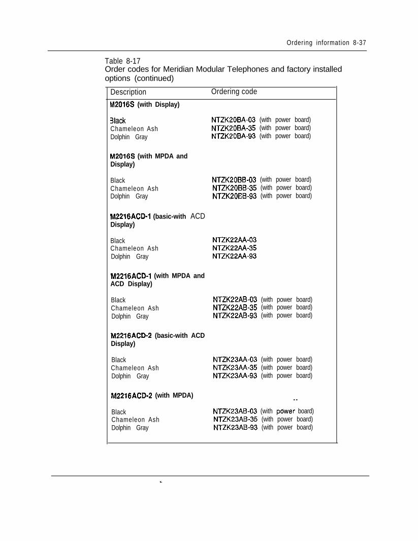
Ordering information 8-37
Table 8-17Order codes for Meridian Modular Telephones and factory installedoptions (continued)
Description Ordering code
M2016S (with Display)
3lack NTZK20BA-03 (with power board)Chameleon Ash NTZK20BA-35 (with power board)Dolphin Gray NTZK20BA-93 (with power board)
M2016S (with MPDA andDisplay)
BlackChameleon AshDolphin Gray
NTZK20BB-03 (with power board)NTZK20BB-35 (with power board)NTZK20EB-93 (with power board)
M2216ACD-1 (basic-with ACDDisplay)
BlackChameleon AshDolphin Gray
NTZK22AA-03NTZK22AA-35NTZK22AA-93
M2216ACD-1 (with MPDA andACD Display)
BlackChameleon AshDolphin Gray
NTZK22AB-03 (with power board)NTZK22AB-35 (with power board)NTZK22AB-93 (with power board)
M2216ACD-2 (basic-with ACDDisplay)
BlackChameleon AshDolphin Gray
NTZK23AA-03 (with power board)NTZK23AA-35 (with power board)NTZK23AA-93 (with power board)
M2216ACD-2 (with MPDA) - -
BlackChameleon AshDolphin Gray
NTZK23AB-03 (with pdwer board)NTZK23AB-35 (with power board)NTZK23AB-93 (with power board)
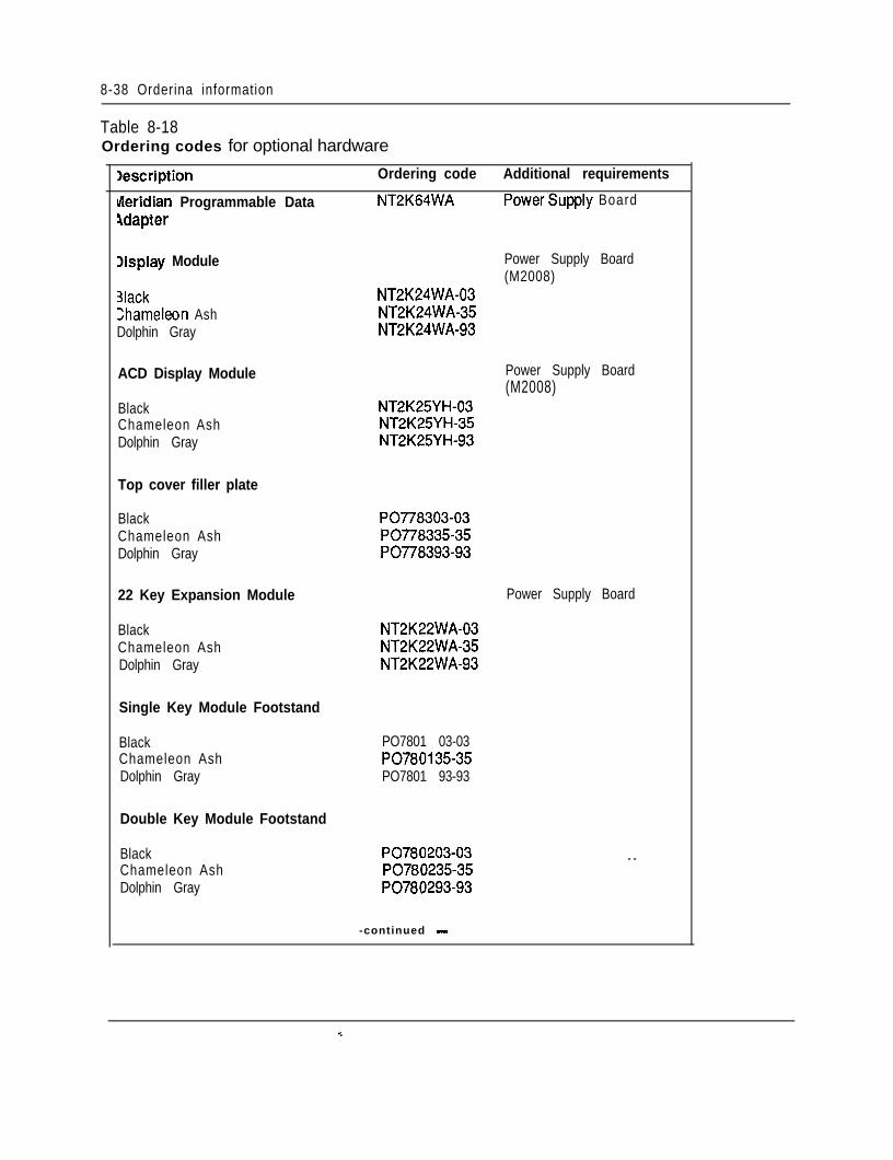
8-38 Orderina information
Table 8-18Ordering codes for optional hardware
Iescription Ordering code Additional requirements
tieridian Programmable Data NT2K64WA PowerSupply BoardAdapter
Xsplay Module
3lack>hameleon AshDolphin Gray
ACD Display Module
BlackChameleon AshDolphin Gray
Top cover filler plate
NT2K24WA-03NT2K24WA-35NT2K24WA-93
NT2K25YH-03NT2K25YH-35NT2K25YH-93
Power Supply Board(M2008)
Power Supply Board(M2008)
BlackChameleon AshDolphin Gray
22 Key Expansion Module
BlackChameleon AshDolphin Gray
Single Key Module Footstand
BlackChameleon AshDolphin Gray
Double Key Module Footstand
BlackChameleon AshDolphin Gray
PO778303-03PO778335-35PO778393-93
Power Supply Board
NT2K22WA-03NT2K22WA-35NT2K22WA-93
PO7801 03-03PO780135-35PO7801 93-93
PO780203-03PO780235-35
- -
PO780293-93
-continued -
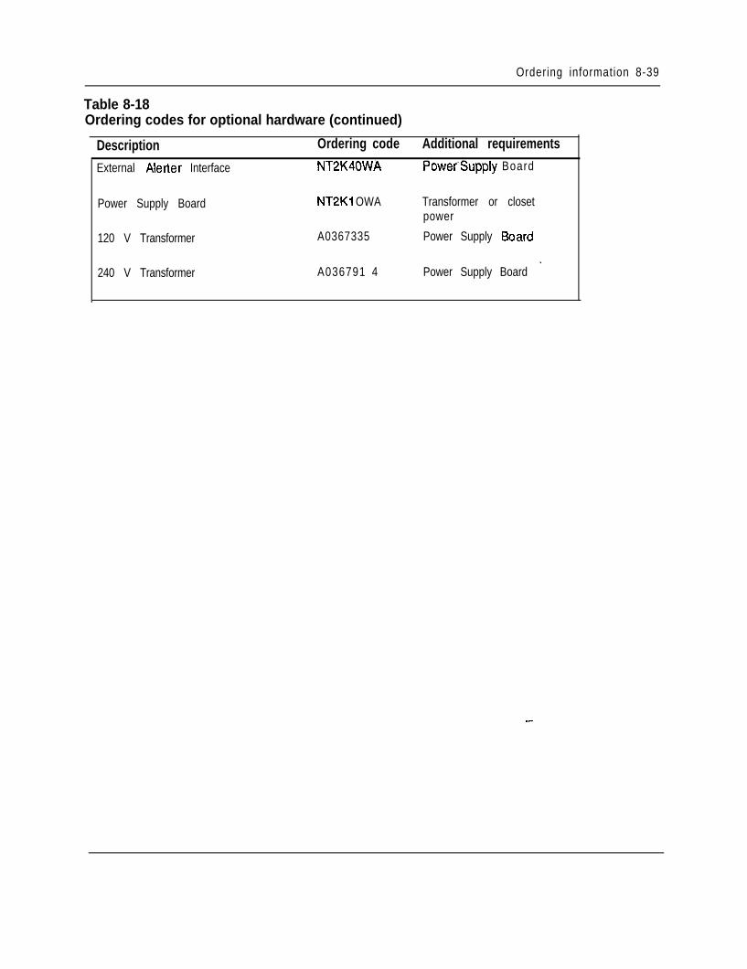
Ordering information 8-39
Table 8-18Ordering codes for optional hardware (continued)
Description Ordering code Additional requirements
External Alerter Interface NT2K40WA
Power Supply Board NT2Ki OWA
120 V Transformer A0367335
240 V Transformer A036791 4
Power’Supply Board
Transformer or closetpower
Power Supply Board
Power Supply Board _
--
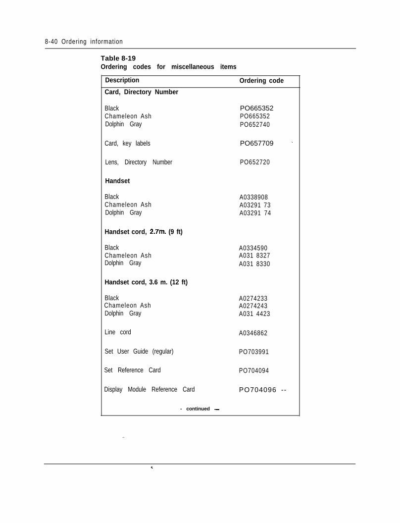
8-40 Ordering information
Table 8-19Ordering codes for miscellaneous items
Description
Card, Directory Number
BlackChameleon AshDolphin Gray
Card, key labels
Lens, Directory Number
Handset
BlackChameleon AshDolphin Gray
Handset cord, 2.7m. (9 ft)
BlackChameleon AshDolphin Gray
Handset cord, 3.6 m. (12 ft)
BlackChameleon AshDolphin Gray
Line cord
Set User Guide (regular)
Set Reference Card
Display Module Reference Card
- continued -
Ordering code
PO665352PO665352PO652740
PO657709 _
PO652720
A0338908A03291 73A03291 74
A0334590A031 8327A031 8330
A0274233A0274243A031 4423
A0346862
PO703991
PO704094
PO704096 --
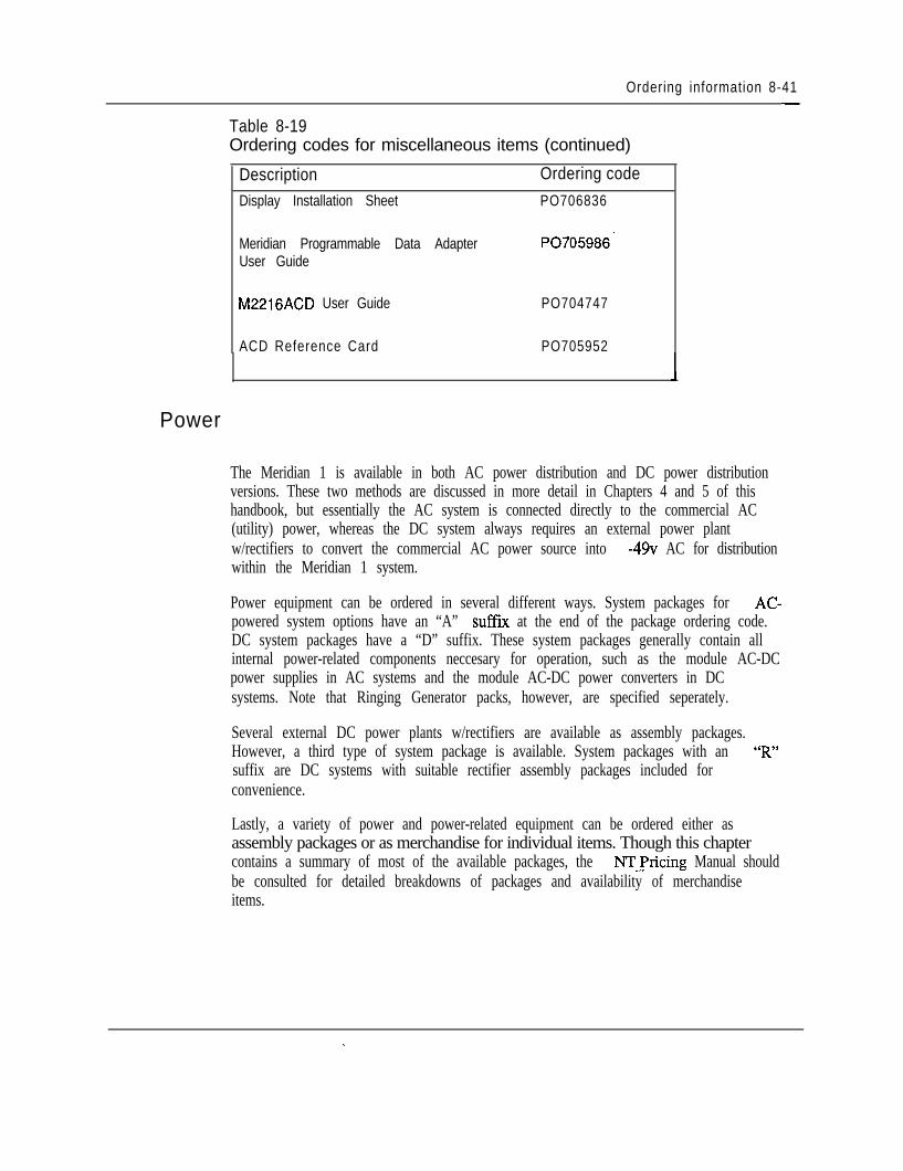
Ordering information 8-41-
Table 8-19Ordering codes for miscellaneous items (continued)
DescriptionDisplay Installation Sheet
Meridian Programmable Data AdapterUser Guide
Ordering codePO706836
PO705986’
M2216ACD User Guide PO704747
ACD Reference Card PO705952
Power
The Meridian 1 is available in both AC power distribution and DC power distributionversions. These two methods are discussed in more detail in Chapters 4 and 5 of thishandbook, but essentially the AC system is connected directly to the commercial AC(utility) power, whereas the DC system always requires an external power plantw/rectifiers to convert the commercial AC power source into -49~ AC for distributionwithin the Meridian 1 system.
Power equipment can be ordered in several different ways. System packages for AC-powered system options have an “A” suffix at the end of the package ordering code.DC system packages have a “D” suffix. These system packages generally contain allinternal power-related components neccesary for operation, such as the module AC-DCpower supplies in AC systems and the module AC-DC power converters in DCsystems. Note that Ringing Generator packs, however, are specified seperately.
Several external DC power plants w/rectifiers are available as assembly packages.However, a third type of system package is available. System packages with an “R”suffix are DC systems with suitable rectifier assembly packages included forconvenience.
Lastly, a variety of power and power-related equipment can be ordered either asassembly packages or as merchandise for individual items. Though this chaptercontains a summary of most of the available packages, the NT$icing Manual shouldbe consulted for detailed breakdowns of packages and availability of merchandiseitems.
. .
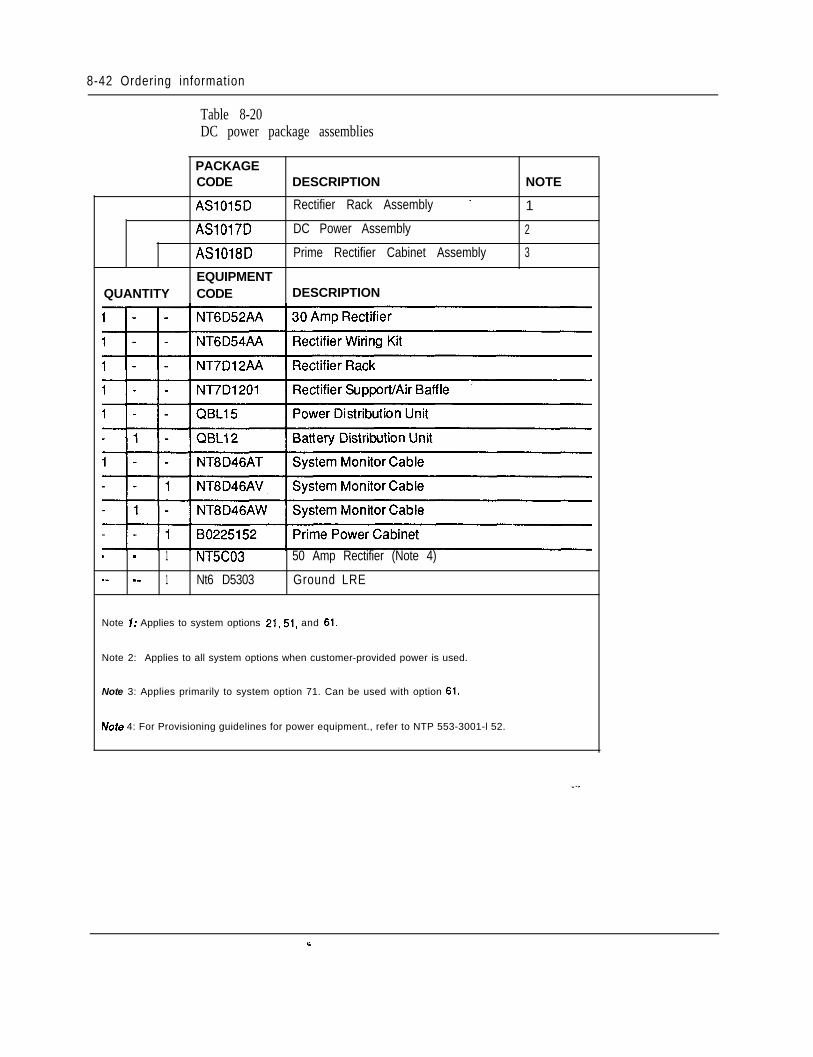
8-42 Ordering information
Table 8-20DC power package assemblies
PACKAGECODE DESCRIPTION NOTE
AS1015D Rectifier Rack Assembly - 1
AS1017D DC Power Assembly 2
AS1018D Prime Rectifier Cabinet Assembly 3
EQUIPMENTQUANTITY CODE DESCRIPTION
_ - 1 NT5C03 50 Amp Rectifier (Note 4)_- -_ 1 Nt6 D5303 Ground LRE
Note 7: Applies to system options 21,51, and 61.
Note 2: Applies to all system options when customer-provided power is used.
Note 3: Applies primarily to system option 71. Can be used with option 61.
Note 4: For Provisioning guidelines for power equipment., refer to NTP 553-3001-l 52.
9-1
Chapter 9: Traffic
ContentsIntroductionTraffic EngineeringTraffic Considerations
9-19-l9 - 4
IntroductionAll telecommunications networks possess two basic types of resources: callprocessing resources and call carrying resources.
Call processing resources set up and take down point-to-pointconnections within the network. They comprise route selection within the network,signaling between switching systems, billing, and control of special functions orfeatures. Call processing resources are usually concentrated within the switchingsystem. They take the form of relay or software-based logic, memory, and digitreceivers/transmitters which are used to exchange signals between switchingsystems.
Call carrying resources are used to support. a point-to-point connectionestablished within the network. These resources consist of subscriber loopsbetween telephones and switching systems, the connections through which a callpasses within switching systems, and the transmission paths between all theswitching systems in an end-to-end connection.
A fundamental quantity called traffic is derived from the product of two factors.One factor is the number of attempts or bids made to use anetwork resource perhour. The other is the average duration in hours that the’ resource is used perattempt.
Traffic engineeringTraffic Engineering predicts me amount of equipment required to provide highquality service at the most economical cost. Most users take excellent telephoneservice for granted. It happens so quickly and automatically that there is a tendencyto believe there are unlimited resources available in the switching network
Engineering Handbook
9-2 Traffic
dedicated to each telephone. However, this is not the case; components of theswitching equipment are shared among many callers. It is the traffic engineeringwhich promotes the illusion of unlimited resources in an economical system.
The high quality of service currently achievable is due in part to the establishmentof and adherence to communication traffic standards. These standards define thequality of service that a user will experience when gaining access to the network toplace a call. In general, the higher the grade of service, the greater the amount ofswitching and transmission resources required. In today’s telecommunicationsenvironment, the task of setting appropriate traffic standards is becomingincreasingly complicated because the nature of traffic is changing. Until recently,traffic engineering consisted primarily of providing an adequate level of telephoneservice. Today, advances in digital technology make it possible to integrate avariety of new communications services into the common network. The trafficcharacteristics of this integrated stream of features differ markedly from those ofbasic telephone traffic in three areas: holding time, number of network connections,and traffic pattern.
The holding time or duration of an ordinary telephone call averages approximatelythree minutes. In an integrated office traffic stream, holding times vary from veryshort (a few seconds to transmit an electronic letter) to very long (30 minutes ormore for a teleconference or a document processing operation).
To determine the impact of these variable holding times on traffic, the parametersthat measure network performance, particularly those for blocking and access delay,must be considered.
Blocking probability is the probability that an attempt to invoke a service will beunsuccessful. At a given traffic level, the probability that blocking will occurincreases as the required number of simultaneous connections increases.
Access delay is the amount of time a user waits to gain access to the service. Inpublic networks, users experience both dial tone delay and post-dialing delay. In aprivate network, access to resources may also be gained on a delay basis,
Measurements of service quality have little meaning unless a standard exists againstwhich they may be compared. Traffic standards must be carefully selected to strikethe correct balance between user service expectations and cost.
Once service is deployed, operational measurements monitor traffic demands andthe resulting quality of service. This data is also used to predict future loadrequirements. The goal of this activity is to ensure that performance objectives aremet both now and in the future. The degree to which this goal is met dependslargely on the accuracy of the traffic forecasts.
The average number of simultaneous calls during a given period is known as thetraffic flow or intensity. The two commonly used units of traffic measurements are:
Engineering Handbook
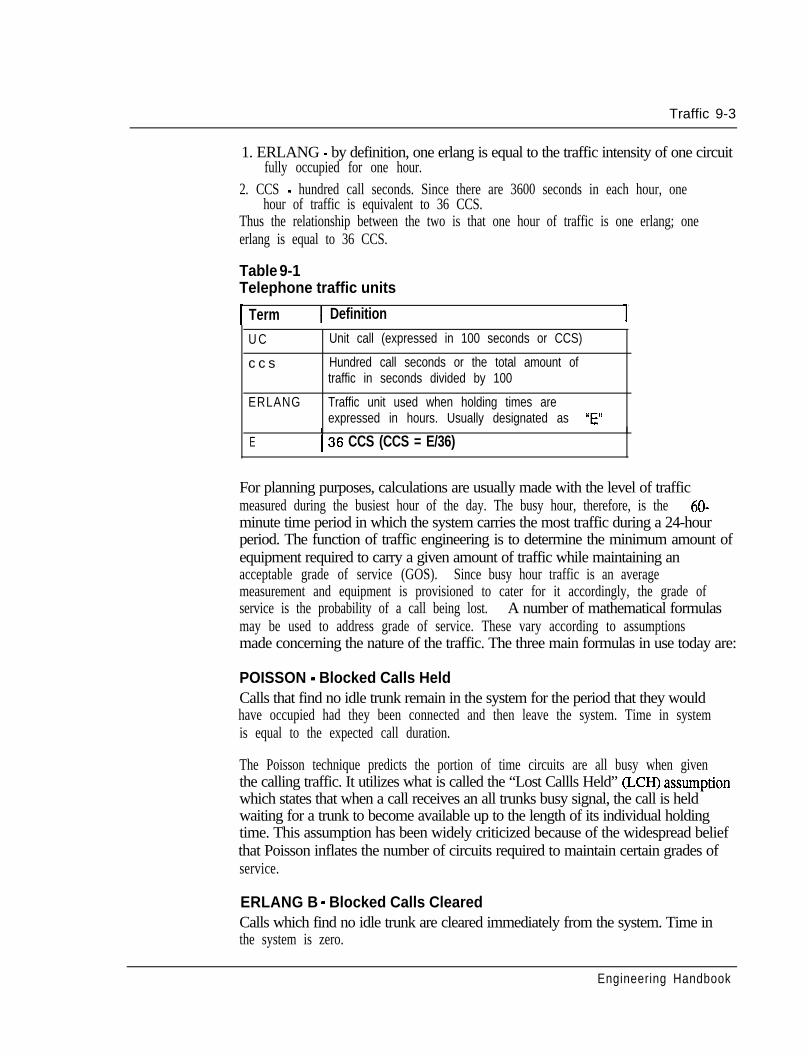
Traffic 9-3
1. ERLANG - by definition, one erlang is equal to the traffic intensity of one circuitfully occupied for one hour.
2. CCS - hundred call seconds. Since there are 3600 seconds in each hour, onehour of traffic is equivalent to 36 CCS.
Thus the relationship between the two is that one hour of traffic is one erlang; oneerlang is equal to 36 CCS.
Table 9-1Telephone traffic units
1 Term 1 Definition
U C Unit call (expressed in 100 seconds or CCS)
c c s Hundred call seconds or the total amount oftraffic in seconds divided by 100
ERLANG Traffic unit used when holding times areexpressed in hours. Usually designated as “E”
I
E I36 CCS (CCS = E/36)
For planning purposes, calculations are usually made with the level of trafficmeasured during the busiest hour of the day. The busy hour, therefore, is the 60-minute time period in which the system carries the most traffic during a 24-hourperiod. The function of traffic engineering is to determine the minimum amount ofequipment required to carry a given amount of traffic while maintaining anacceptable grade of service (GOS). Since busy hour traffic is an averagemeasurement and equipment is provisioned to cater for it accordingly, the grade ofservice is the probability of a call being lost. A number of mathematical formulasmay be used to address grade of service. These vary according to assumptionsmade concerning the nature of the traffic. The three main formulas in use today are:
POISSON - Blocked Calls HeldCalls that find no idle trunk remain in the system for the period that they wouldhave occupied had they been connected and then leave the system. Time in systemis equal to the expected call duration.
The Poisson technique predicts the portion of time circuits are all busy when giventhe calling traffic. It utilizes what is called the “Lost Callls Held” (LCH) assumptionwhich states that when a call receives an all trunks busy signal, the call is heldwaiting for a trunk to become available up to the length of its individual holdingtime. This assumption has been widely criticized because of the widespread beliefthat Poisson inflates the number of circuits required to maintain certain grades ofservice.
ERLANG B - Blocked Calls ClearedCalls which find no idle trunk are cleared immediately from the system. Time inthe system is zero.
Engineering Handbook
9-4 Traffic
Erlang B is a very accurate technique for predicting both blocking and trunk usage,particularly when alternate routes are automatically selected upon encounteringblockage.
ERLANG C - blocked calls delayedCalls which find no idle trunk wait in a queue until a trunk is free and then areconnected normally. Time in system is equal to the waiting time plus the expectedcall duration.
Erlang C is the technique used when calls are queued but has the limitation ofassuming all callers encountering a delay will be willing to wait an indefinite periodof time to be connected.
In summary, there are justified indictments against the traffic engineeringtechniques of Poisson, Erlang B, and Erlang C that result in a void in the capabilityof accounting for the way customers utilize today’s enhanced communicationservices. The most pervasive influence on traffic standards comes from thedevelopment of new services. The way users perceive and interact with the networkis changing, particularly in the business community, as the electronic officebecomes a reality. The traditional objective of high quality service must bebalanced against the cost of deploying the service using the available technology.The Meridian 1, with its flexible architecture, distributed network, and inherenttraffic measurement capabilities, can be suitably configured to meet any trafficengineering application with minimum penalty to cost.
Traffic considerationsMany different analytical methods have been used for calculating the trafficcapacity of the Meridian 1. Theoretical analysis, substantiated by simulation of theswitching system, resulted in an admissable region of traffic handling capability thatwould satisfy intraloop and interloop blocking probabilities. Service loops were notconsidered in the simulation, since most of the services (such as dial tone) operateon a delay basis without contributing to the loss of traffic.
Grade of serviceThe following grade of service objectives are utilized for the switching network:(a) No more than 1.5 percent of the originating calls have to wait more than 3
seconds for dial tone.
(b) No more than 1 percent of the incoming terminating callswill% lost providedthe called line was free.
(c) No more than 1 percent of the originating outgoing calls will be lost in thesystem (excluding the loss due to the outgoing trunks being unavailable).Furthermore, no more than 2 percent of the calls will be lost due to all thetrunks being busy.
(d) No more than 4 percent of the intraoffice calls will be lost provided the calledline was free.
Engineering Handbook
Traffic 9-5
The grade of service (a) is concerned with dial tone delay specifications. The gradeof service (b), (c), and (d), in effect, deal with the switching network and routeblocking. Incoming, outgoing, and intraoffice matching losses are related tointraloop and interloop blocking probabilities.
Specification (d) requires that these blocking probabilities be less than 4 percent,
Specification (b) means that 1 percent is the allowable limit on blocking forincoming terminating calls.
Specification (c) refers to the congestion in the switching network for an outgoingcall and the maximum allowable blocking probability for this case is 1 percent.
A retrial procedure is used on outgoing trunks in attempting to find an availablepath through the network. Hence the blocking probability for the outgoing callswill be less than that for incoming calls. Thus if specification (b) is satisfied,specification (c) is automatically satisfied for the switching network.
It should be noted that these are desirable guidelines to optimize networkperformance for the maximum number of terminations on a network loop. In thepractical sense, a mix of peripheral interface cards more often results in fewerterminations being serviced by the network loop. With less contention for timeslots, the traffic handling capability exceeds the grade of service objectives andincreases the traffic capacity of the network loop. Since any type of peripheraldevice (telephone, terminal, trunk, data unit, digitone receiver, etc.) may be used ina connection, the traffic capacity is obtained as the traffic that can be carried by alltime slots in a loop. The sum of the traffic generated by all associated peripheralterminations constitutes what is known as the loop traffic.
In order to achieve the lowest blocking probability, traffic should be evenlydistributed over the available network loops. This is termed load balancing and isimplemented to more readily accommodate variable traffic patterns. However, thisprocedure is quite meaningless if based upon unsubstantiated traffic projectionsprior to system installation. Although balanced from a theoretical point of view andengineered to meet grade of service recommendations, the allocation of users toperipheral devices and their subsequent network resource activity is the maincriteria for achieving optimum system performance. It makes more sense to assignapproximately the same number and type of terminals on each network loop andutilize the inherent system traffic measurement capabilities to determine ifreassignments are necessary. All too often, inflationary traffic forecasts are madewithout substance and applied arbitrarily to system engineering. The result is aconfiguration that adopts a very conservative approach to traffic handlingcapability.
Non network enhanced systemsThe original SL- 1 network design utilized a procedure of selecting time slots from aset of admissable pairs. This method of searching for free time slots in admissable
Engineering Handbook
9-6 Traffic
pairs was utilized in two of the Meridian SL-1 business system offerings--models Sand MS. The concept readily met the traffic demands of small system applications.It was also utilized in the LE and XL in support of Software Generics 337 and 637respectively. However, in recognition of me need to enhance and provide moreswitching capability to address the ongoing requirements of both voice and data, anew network design was introduced in 1984.
Network enhancementThe traffic impacts of network enhancement are two-fold: _
The removal of the time slot pairing constraint between originating andterminating calls. The selection of time slots on an individual basis reducedmismatch probability, improved network capacity, and provided the capabilityfor a non-blocking matrix. The net effect was an increase in loop capability ofapproximately ten per cent (lo%), i.e., from 600 CCS/loop to 660 CCS/loop for160 PE terminations based on the Erlang B. model as before.The doubling of network loops within a group. In the enhanced network design,the number of loops in a group is doubled from 16 to 32. The associatednetwork card supports two loops. The number of inter-group junctors was alsoincreased from 4 to 8 to improve the grade of service and reduce blockingprobability in the multi-group system.
These enhancements were instrumental in the formation of two Meridian SL- 1system models - N and XN. The network design has since been incorporated in theMeridian SL-1 ST, Meridian SL-1 RT, Meridian SL-1 NT, and Meridian SL-1 XT.The Superloop, introduced on Meridian 1 System Options 21,51, 61, and 71, is alsobased upon the network enhancement.
The unavailability of a time slot for call set up is a function of the amount of trafficthen loaded on the loop (both voice and data) and, therefore, blockage due to alltime slots being busy is the same for both voice calls and data calls. However, if thetraffic level for different traffic sources varies significantly, the type of trafficsources with a lower load could encounter blocking if too many heavy trafficsources also generate traffic to the same circuit group. It is for this reason that datatraffic, with its typically long holding times, be limited on inter-group junctors.
Network enhancement provides the viable alternative of assigning all data lines on aloop and data traffic within a group to effectively isolate the impact on voice traffic.It also provides complete flexibility in engineering network loops throughout thesystem to address the varying demands of both voice and data traffic accordingly.
Depending upon the origination and termination of a call, several situationscontribute to the blocking probability, based on Erlang B formula at the networkloop.
Intra-loop, Intra-group blockingFor an intra-loop intra-group call, blocking will occur when idle time slots in thenetwork loop are less than two.
Engineering Handbook
Traffic 9-7
Inter-loop, Intra-group blockingBlocking of this type could occur when a call encounters no idle time slot at eitherthe originating loop or terminating loop.
Inter-loop, Intergroup blockingCalls of this type can be blocked at originating loop, terminating loop, and inter-group junctors. A junctor is served as an extension of the originating andterminating loop; the same time slot at both junctor and originating loop must beidle in order to succeed in the first half of the connection. A similar match is alsorequired at the terminating side. The time slot at the terminating loop isindependent of the originating time slot.
Each inter-group call initiated requires two idle time slots on the junctors to set upthe path; one time slot on the originating junctor to match the originating loop andanother time slot on the terminating junctor to match the terminating loop. In otherwords, one inter-group call makes two time slots on the junctors busy, one on eachgroup of junctors. Since both originating and terminating traffic between twonetwork groups pass the same sets of junctors, a junctor group handles traffic fromboth directions, even though it is associated with only one network group.
Inter-loop, Intra-group calls with small traffic sourcesThis type of call is of particular interest since for heavy data applications, thenumber of terminations per network loop could be relatively small due to high CCSper data line requirements. In order to reduce blocking, high traffic data lines andcomputer ports are not recommended to be in the same network loop (since an intra-loop call takes two time slots from the same loop) or different groups (to minimizejunctor traffic). Therefore, most calls from loops with small traffic sources shoulduse inter-loop intra-group connections. The reduction in the number of terminationspermits the use of the Engset formula for finite sources in place of the Erlang lossformula for infinite sources.
The Engset formula, like Erlang B, is a loss-call-cleared model with a finite sourceassumption which is applicable when the number of traffic sources to channels ratiois small. The finite source model predicts a higher capacity since it includes thenumber of traffic sources as a parameter in the model. When a certain number ofchannels or time slots are occupied, the model will correspondingly reduce thenumber of idle sources which could potentially generate traffic to the channels.Therefore, the projected blocking is reduced and the allowed traffic would begreater for the finite Engset source model than that for the Erlang B model since thelatter has a constant rate of service demand.
Utilization of the Engset model is appropriate for those Meridian 1 and MeridianSL-1 models that incorporate network enhancement and have a traffic source tochannel ratio of approximately 4: 1 or less. Therefore, it is appropriate forapplications where a network loop of 30 traffic channels services up to 120peripheral ports or traffic sources. For Meridian SL-1 applications, this is
Engineering Handbook
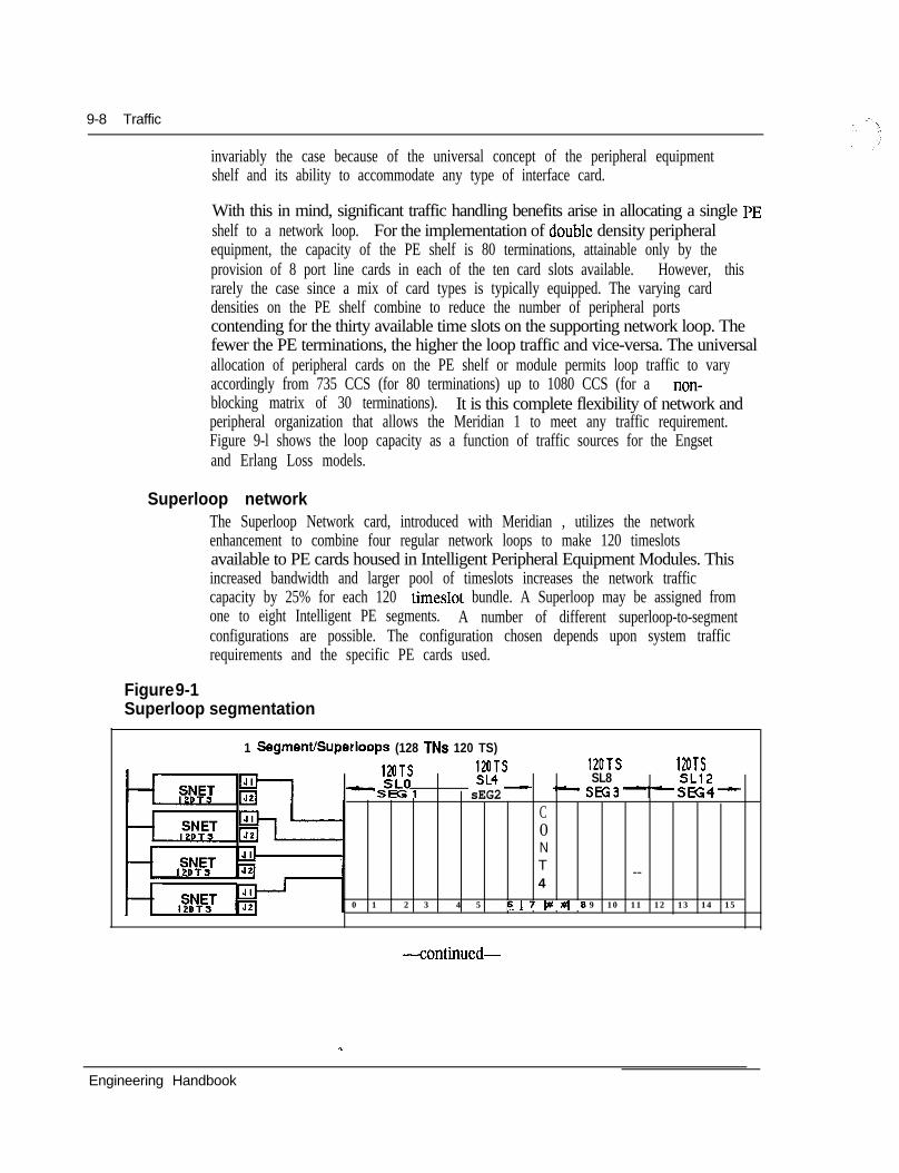
9-8 Traffic
invariably the case because of the universal concept of the peripheral equipmentshelf and its ability to accommodate any type of interface card.
With this in mind, significant traffic handling benefits arise in allocating a single PEshelf to a network loop. For the implementation of double density peripheralequipment, the capacity of the PE shelf is 80 terminations, attainable only by theprovision of 8 port line cards in each of the ten card slots available. However, thisrarely the case since a mix of card types is typically equipped. The varying carddensities on the PE shelf combine to reduce the number of peripheral portscontending for the thirty available time slots on the supporting network loop. Thefewer the PE terminations, the higher the loop traffic and vice-versa. The universalallocation of peripheral cards on the PE shelf or module permits loop traffic to varyaccordingly from 735 CCS (for 80 terminations) up to 1080 CCS (for a non-blocking matrix of 30 terminations). It is this complete flexibility of network andperipheral organization that allows the Meridian 1 to meet any traffic requirement.Figure 9-l shows the loop capacity as a function of traffic sources for the Engsetand Erlang Loss models.
Superloop networkThe Superloop Network card, introduced with Meridian , utilizes the networkenhancement to combine four regular network loops to make 120 timeslotsavailable to PE cards housed in Intelligent Peripheral Equipment Modules. Thisincreased bandwidth and larger pool of timeslots increases the network trafficcapacity by 25% for each 120 timeslot bundle. A Superloop may be assigned fromone to eight Intelligent PE segments. A number of different superloop-to-segmentconfigurations are possible. The configuration chosen depends upon system trafficrequirements and the specific PE cards used.
Figure 9-1Superloop segmentation
1 SegmenVSuperloops (128 TNs 120 TS)
12OTS:zs- --
120TS 12OTS- SLO SL8 SLl2
Sffil sEG2 sK;3--sEG4-C0NT --4
0 1 2 3 4 5 67w#6 9 10 11 12 13 14 15
-continued-
Engineering Handbook
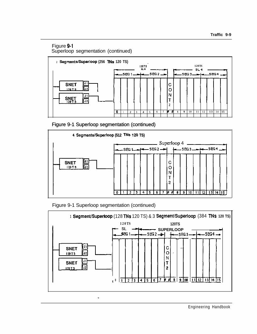
Traffic 9-9
Figure 9-lSuperloop segmentation (continued)
I2 SegmenWSuperloop (256 TNs 120 TS)
WITS‘ 120TS
--Efl;fi
2
0 1 2 3 4 5 6 7 I# # 6 9 10 11 12 13 14 15
Figure 9-1 Superloop segmentation (continued)Figure 9-1 Superloop segmentation (continued)
4 SegmentslSuperloop (512 TNs 120 TS)4 SegmentslSuperloop (512 TNs 120 TS)
Figure 9-1 Superloop segmentation (continued)
1 Segment/Superloop (128 TNs 120 TS) & 3 Segmenthperloop (384 TNs 120 TS)
120TS
t 0
120TS- SUPERLOOP 4
C0 ’NIT2
7 # a 19 106--sEG4-m
Engineering Handbook
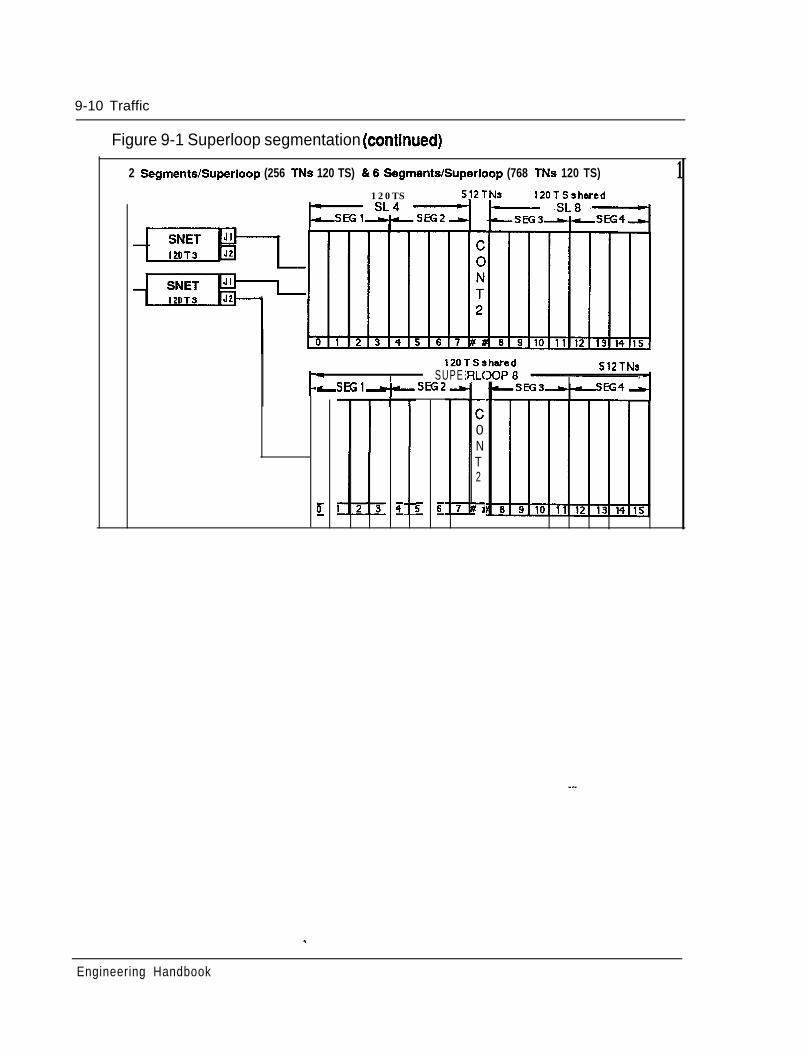
9-10 Traffic
Figure 9-1 Superloop segmentation (continued)
12 Segments/Superloop (256 TNs 120 TS) 816 SegmentdSuperloop (768 TNs 120 TS)
120TS 5j2TNt 120TSshared
12OTSshared3OP8b SUPE
LsEGl-+-sEG2a
512TNs,
E f E H
L(
c0NT2
E
F
Engineering Handbook
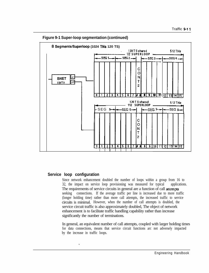
Traffic 9-l I
Figure 9-1 Super-loop segmentation (continued)
8 SegmenWSuperloop (1024 TNs 120 TS)120TSshared 512TNs
pm l/2 SUPERLOOP pI
a8 9 10 11
120TSshwed 512TNs112 SUPERLOOP --I
cSEG 6-4-SEG h -sEG +SEG hj
Service loop configurationSince network enhancement doubled the number of loops within a group from 16 to32, the impact on service loop provisioning was measured for typical applications.The requirements of service circuits in general are a function of call attemptsseeking connections. If the average traffic per line is increased due to more traffic(longer holding time) rather than more call attempts, the increased traffic to servicecircuits is minimal. However, when the number of call attempts is doubled, theservice circuit traffic is also approximately doubled, The object of networkenhancement is to facilitate traffic handling capability rather than increasesignificantly the number of terminations.
In general, an equivalent number of call attempts, coupled with larger holding timesfor data connections, means that service circuit functions arc not adversely impactedby the increase in traffic loops.
Engineering Handbook
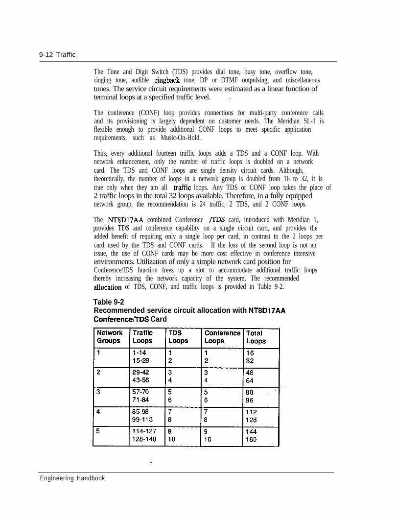
9-12 Traffic
The Tone and Digit Switch (TDS) provides dial tone, busy tone, overflow tone,ringing tone, audible ringback tone, DP or DTMF outpulsing, and miscellaneoustones. The service circuit requirements were estimated as a linear function ofterminal loops at a specified traffic level. -
The conference (CONF) loop provides connections for multi-party conference callsand its provisioning is largely dependent on customer needs. The Meridian SL-1 isflexible enough to provide additional CONF loops to meet specific applicationrequirements, such as Music-On-Hold.
Thus, every additional fourteen traffic loops adds a TDS and a CONF loop. Withnetwork enhancement, only the number of traffic loops is doubled on a networkcard. The TDS and CONF loops are single density circuit cards. Although,theoretically, the number of loops in a network group is doubled from 16 to 32, it istrue only when they am all traffic loops. Any TDS or CONF loop takes the place of2 traffic loops in the total 32 loops available. Therefore, in a fully equippednetwork group, the recommendation is 24 traffic, 2 TDS, and 2 CONF loops.
The NT8D17AA combined Conference /‘IDS card, introduced with Meridian 1,provides TDS and conference capability on a single circuit card, and provides theadded benefit of requiring only a single loop per card, in contrast to the 2 loops percard used by the TDS and CONF cards. If the loss of the second loop is not anissue, the use of CONF cards may be more cost effective in conference intensiveenvironments. Utilization of only a simple network card position forConference/IDS function frees up a slot to accommodate additional traffic loopsthereby increasing the network capacity of the system. The recommendedallocation of TDS, CONF, and traffic loops is provided in Table 9-2.
Table 9-2Recommended service circuit allocation with NT8D17AAConference/TDS Card
Engineering Handbook
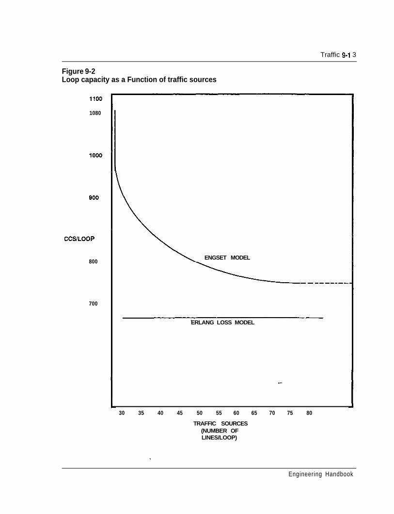
Traffic 9-l 3
Figure 9-2Loop capacity as a Function of traffic sources
1080
CCS/LOOP
800
700
ENGSET MODEL
ERLANG LOSS MODEL
--
30 35 40 45 50 55 60 65 70 75 80
TRAFFIC SOURCES(NUMBER OFLINES/LOOP)
..
Engineering Handbook

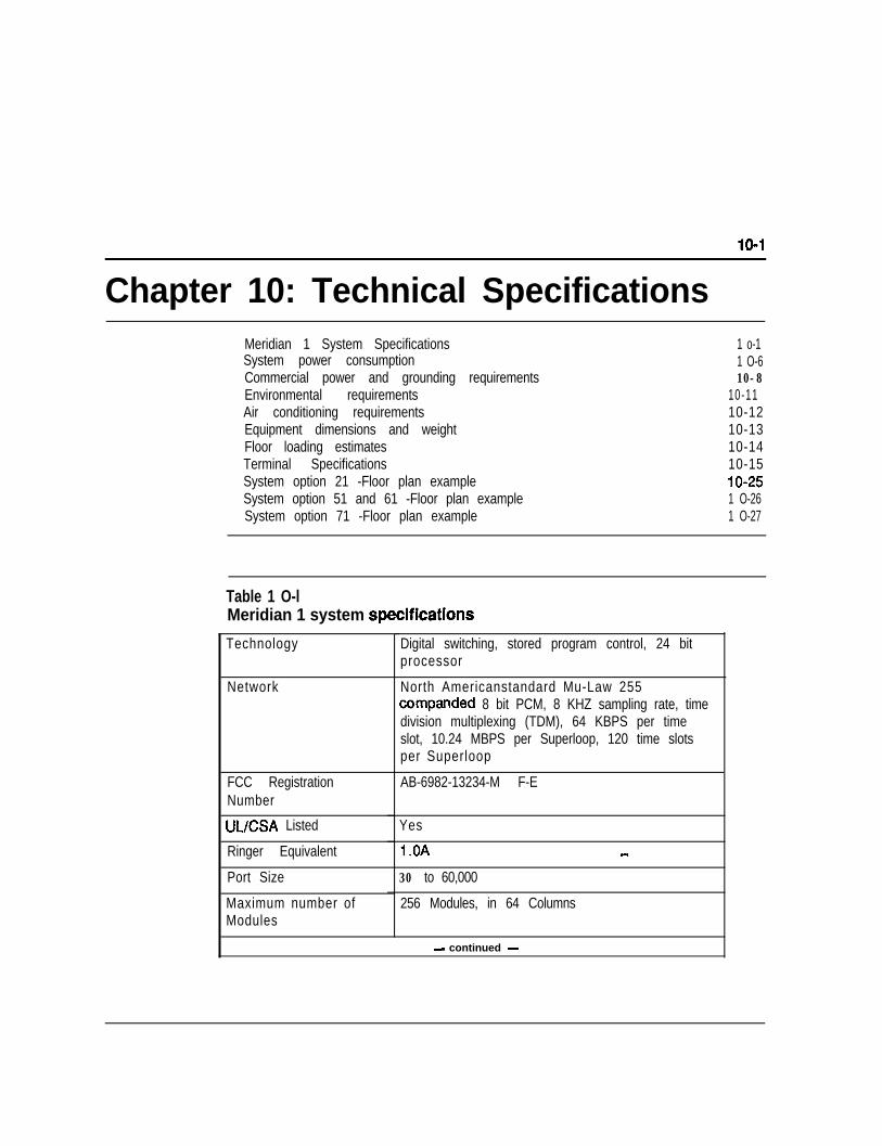
10-l
Chapter 10: Technical SpecificationsMeridian 1 System SpecificationsSystem power consumptionCommercial power and grounding requirementsEnvironmental requirementsAir conditioning requirementsEquipment dimensions and weightFloor loading estimatesTerminal SpecificationsSystem option 21 -Floor plan exampleSystem option 51 and 61 -Floor plan exampleSystem option 71 -Floor plan example
1 o-11 O-610-8
10-1110-1210-1310-1410-15lo-251 O-261 O-27
Table 1 O-lMeridian 1 system speCifiCatiOnS
Technology
Network
FCC RegistrationNumber
UUCSA Listed
Ringer Equivalent
Port Size
Maximum number ofModules
Digital switching, stored program control, 24 bitprocessor
North Americanstandard Mu-Law 255companded 8 bit PCM, 8 KHZ sampling rate, timedivision multiplexing (TDM), 64 KBPS per timeslot, 10.24 MBPS per Superloop, 120 time slotsper Superloop
AB-6982-13234-M F-E
Yes
-
30 to 60,000
256 Modules, in 64 Columns
- continued -
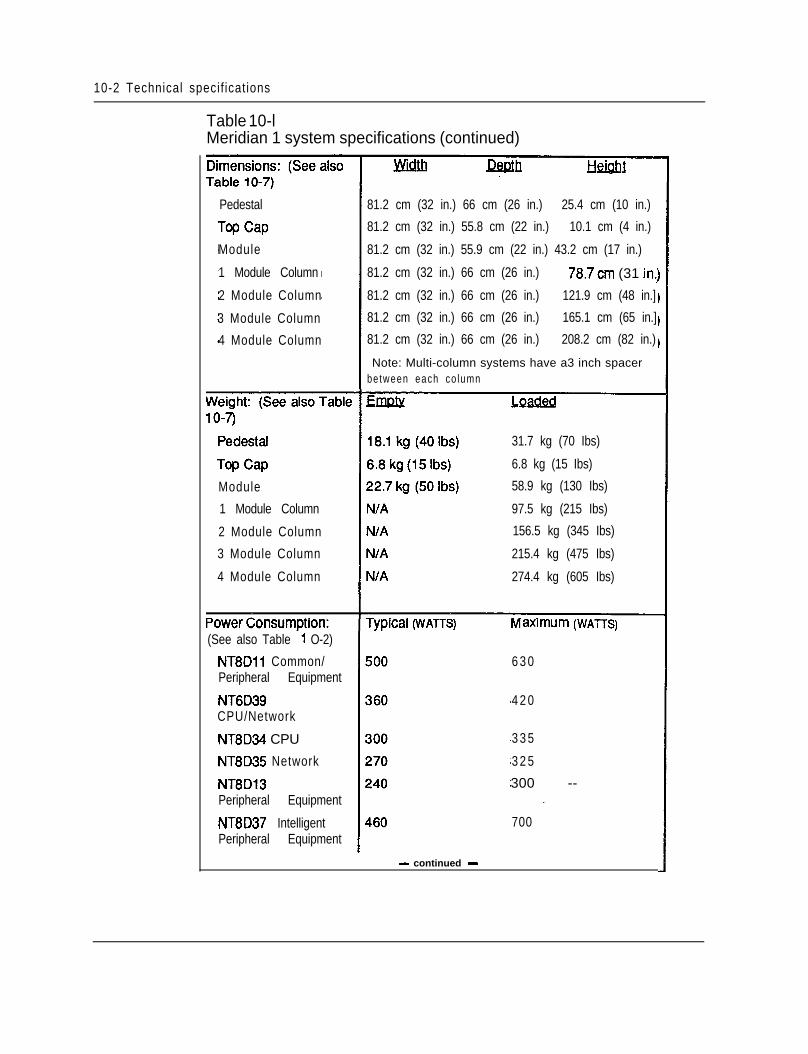
10-2 Technical specif ications
Table 10-lMeridian 1 system specifications (continued)
Pedestal
Module
1 Module Column
2 Module Column
3 Module Column
4 Module Column
81.2 cm (32 in.) 66 cm (26 in.) 25.4 cm (10 in.)
81.2 cm (32 in.) 55.8 cm (22 in.) 10.1 cm (4 in.)
81.2 cm (32 in.) 55.9 cm (22 in.) 43.2 cm (17 in.)
81.2 cm (32 in.) 66 cm (26 in.) 78.7cm (31 in::
81.2 cm (32 in.) 66 cm (26 in.) 121.9 cm (48 in.]
81.2 cm (32 in.) 66 cm (26 in.) 165.1 cm (65 in.]
81.2 cm (32 in.) 66 cm (26 in.) 208.2 cm (82 in.)
Note: Multi-column systems have a3 inch spacerbetween each co lumn
Module
1 Module Column
2 Module Column
3 Module Column
4 Module Column
31.7 kg (70 Ibs)
6.8 kg (15 Ibs)
58.9 kg (130 Ibs)
97.5 kg (215 Ibs)
156.5 kg (345 Ibs)
215.4 kg (475 Ibs)
274.4 kg (605 Ibs)
(See also Table 1 O-2)
NT8Dll Common/Peripheral Equipment
NT6D39CPU/Network
NT8D34 CPU
NT8D35 Network
NT8D13Peripheral Equipment
NT8D37 IntelligentPeripheral Equipment
- continued -
axrmum (WAITS)
6 3 0
4 2 0
3 3 5
3 2 5
300 --
700
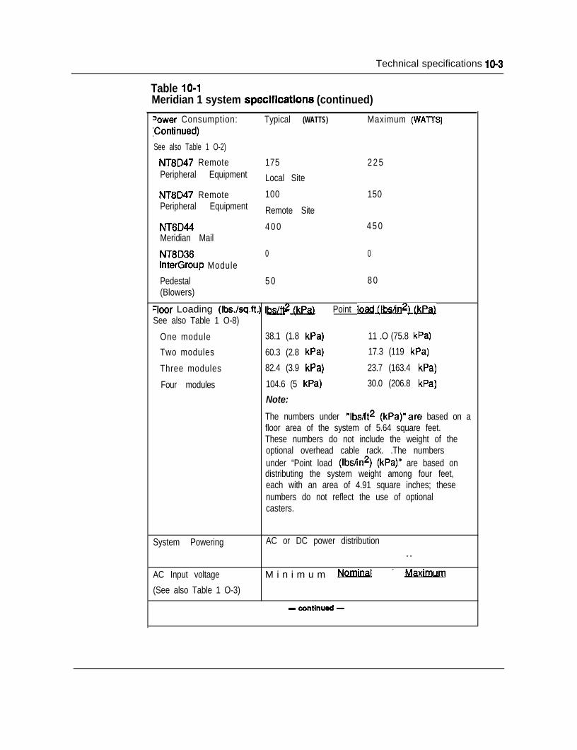
Technical specifications 10-3
Table 10-lMeridian 1 system specifications (continued)
Jower Consumption: Typical (WATTS) Maximum (WATTS):Continued)
See also Table 1 O-2)
NT8D47 Remote 175 2 2 5Peripheral Equipment Local Site
NT8D47 Remote 100 150Peripheral Equipment Remote Site
NT6D44 4 0 0 4 5 0Meridian Mail
NT8D36 0 0InterGroup Module
Pedestal 5 0 8 0(Blowers)
‘loor Loading (Ibs./sq.ft.) l&(kPa) Point ~Jf&$)&.&)See also Table 1 O-8)
One module 38.1 (1.8 kPa) 11 .O (75.8 kPa)
Two modules 60.3 (2.8 kPa) 17.3 (119 kPa)
Three modules 82.4 (3.9 kPa) 23.7 (163.4 kPa)
Four modules 104.6 (5 kPa) 30.0 (206.8 kPa)
Note:
The numbers under “lbsJt2 (kPa)“are based on afloor area of the system of 5.64 square feet.These numbers do not include the weight of theoptional overhead cable rack. .The numbersunder “Point load (Ibs/in2) (kPa)” are based ondistributing the system weight among four feet,each with an area of 4.91 square inches; thesenumbers do not reflect the use of optionalcasters.
System Powering AC or DC power distribution- -
AC Input voltage M i n i m u m Nominal’Maximum
(See also Table 1 O-3)
- continued -
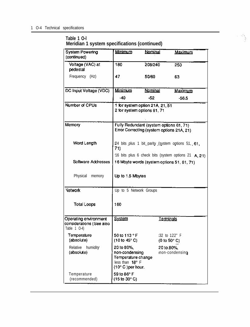
1 O-4 Technical specifications
Table 1 O-lMeridian 1 system specifications (continued)
Frequency (Hz)
24 bits plus 1 bit parity (system options 51,
16 bits plus 6 check bits (system options 21
Physical memory
Vetwork Up to 5 Network Groups
Table 1 O-4)
Relative humidity
less than 18” F
32 to 122” F
non-condensing
Temperature(recommended)
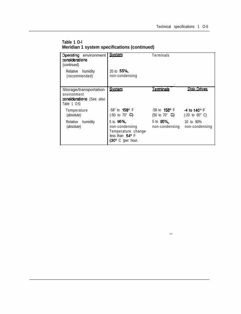
Technical specifications 1 O-5
Table 1 O-lMeridian 1 system specifications (continued)
Cperating environment Svstem Terminalsconsiderations(continued)
Relative humidity 20 to 55%,(recommended) non-condensing
Storage/transportation SvstemTerminals‘
snvironmentconsiderations (See alsoTable 1 O-5)
Temperature -58” to 156’ F -58 to 158’ F -4to14O”F(absolute) (-50 to 70” C) (50 to 70” C) (-20 to 60” C)
Relative humidity 5 to 95%, 5 to 95%, 10 to 90%(absolute) non-condensing non-condensing non-condensing
Temperature changeless than 54” F(30” C )per hour.
--
10-6 Technical specifications
System power consumptionFor detailed system power calculations, the typical and worst caSe powerconsumption figures for each full module are shown in the following table.
The “typical power” figures are fully adequate for use in system power engineeringcalculations, since they are representative of most systems -with Modules fullyloaded (configured) with cards, and under moderate traffic conditions (25%continuous active traffic on lines, 75% continuous active traffic on trunks). Thesefigures am recommended for use in rectifier and reserve power provisioning.
The “maximum power” figures axe shown for reference and planning purposeswhen needed, and were calculated for each module based on a fully-loaded cardcage, in the “worst-possible” operational configuration (in terms of powerconsumption), with each card consuming typical power under 100% traffic, plus10% added margin. For example, the maximum power consumption for theNT8D37 Intelligent Peripheral Equipment Module was based on a configuration ofsixteen NT8D14AA 8-port Universal Trunk cards, all under 100% trafficconditions, along with a Controller card, additional power margin, etc.
All figures in this section am given in real power (unit of Watts) for simplicity. Inaddition, all of the stated numbers have already taken the average efficiency of theModule power supplies into account. To convert to DC current (in amps), dividethe total system power figure by 52 Vdc. This will give the total DC system load inamps. If batteries arc present for reserve power, additional current must beallocated for changing the batteries, according to battery manufacturer’s guidelines.
To convert power to AC current (in amps), divide the total system power figure by208 Vat nominal, or 240 Vat nominal, as appropriate. For calculations normallydone in apparent, or complex, power, such as AC wire and panel size, UPS ratingfor AC reserve power, etc, simply divide the total real power (in Watts) by thetypical system power factor of 0.6 to obtain the complex power (in VA).
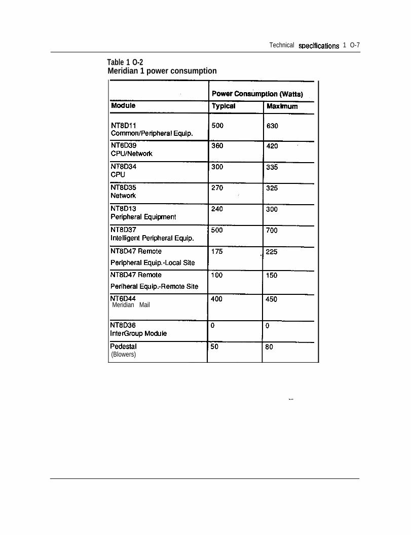
Technical mecifications 1 O-7
Table 1 O-2Meridian 1 power consumption
NT8Dll
Meridian Mail
(Blowers)
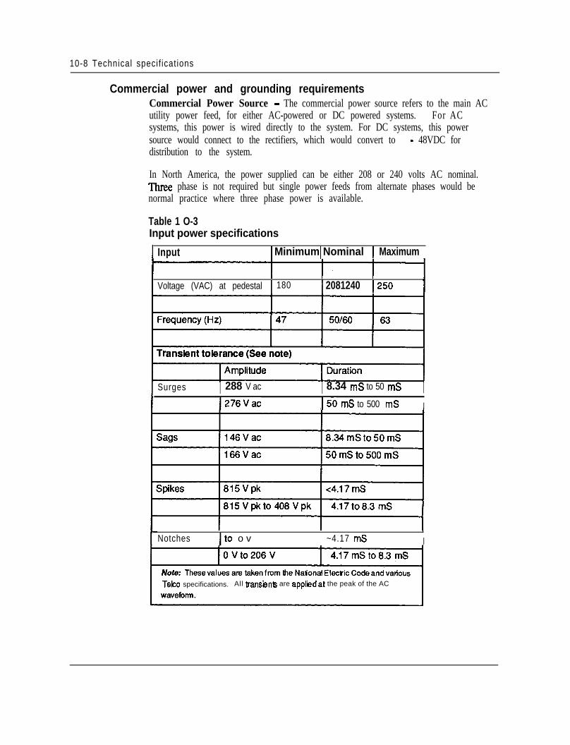
10-8 Technical specif ications
Commercial power and grounding requirementsCommercial Power Source - The commercial power source refers to the main ACutility power feed, for either AC-powered or DC powered systems. For ACsystems, this power is wired directly to the system. For DC systems, this powersource would connect to the rectifiers, which would convert to - 48VDC fordistribution to the system.
In North America, the power supplied can be either 208 or 240 volts AC nominal.Three phase is not required but single power feeds from alternate phases would benormal practice where three phase power is available.
Table 1 O-3Input power specifications
Input 1 Minimum 1 Nominal 1 Maximum
I I I
Voltage (VAC) at pedestal 180 1 2081240 I250
Surges I 288 V ac I 8.34 mS to 50 mS II276Vac I50 mS to 500 mS I
Notches It0 o v ~4.17 mS I
Telco specifications. All transienb are appl i idat the peak of the AC
Technical specifications 1 O-9
All power feeds used should contain a separate safety conductor (green wire).Northern Telecom strongly recommends that the supply conductors be dedicatedand uninterrupted from a building primary source to a dedicated equipment roomsub-panel.
Power Sub-Panel.- Power subpanels must meet the following requirements or bemodified when used for the Meridian 1:. Panels should be located in the equipment mom.l No lighting, air conditioning, heating, generators or motors shall be serviced
from this equipment room panel.l In areas where isolated ground systems are permissible, this panel will provide
sufficient ground connection points on the isolated ground plate or bar to handlethe AC circuit grounds as well as the other ground reference conductorsassociated with the Meridian 1.
Service Receptacles - One dedicated outlet per pedestal (column) is a typicalrequirement for AC systems. For DC systems, or if reserve power is being used,the receptacles or conduit will serve the centralized rectifiers or UPS systemdirectly, with power then routing to the columns.
Unless otherwise specified, these circuits should be rated for 30 Amps. All circuitsmust be:. Wired and fused independently of all receptacles.. Tagged at the power panel to prevent unauthorized interruption of power.l Not controlled by a switch.
The NEMA receptacle types are as follows:
l Isolated Ground systems: IG-L6-30l Non-Isolated Ground systems: L6-30
* In particular, all AC System Options require one 30 A receptacle per column. For DC Systems, those usingthe NTXO3 50A rectifier, require one 30A receptacle per rectifier. The NT6D52AA 30A rectifier, while ithad previously used a 20A input circuit, has been changed to use one 30A receptacle per rectifier, forconsistency throughout the product line. - -
1 O-1 0 Technical specifications
Commercial power conditioningIf the quality of the commercial power source continuously meets the Meridian 1system requirements listed in this section, a power conditioner is not required;however, where the commercial power is of poor quality and cannot consistentlymeet the Meridian 1 system requirements, a-power conditioner may provide someimprovement.
,
Note: When using power conditioning equipment, simply install theequipment in series with the commercial power feed. Do not modify theMeridian 1 system grounding scheme.
System grounding requirementsEssential to trouble-free system operation and the safety of personnel is theemployment of proper grounding. The Meridian 1 has several different groundsand signal returns that are generally referred to as grounds: logic return, batteryreturn (for DC systems), AC “green wire” equipment ground (in AC systems), andthe personal hazard equipment ground.
The Meridian 1 does not, by design, need an AC Isolated Ground (IG) system(though this is typically required by local codes such as NEC), but it does need asingle point ground system. This means that each of the various grounds, fromeach of the columns, should terminate at a single connection point before attachingto the actual ground reference at the main AC panel or transformer. The single-point ground may be implemented either by the use of the Isolated Ground bus inthe AC panel, or by a separate logic return equalizing bus for battery returns andlogic returns where a non-isolated AC system is used.
The following must also be observed to implement the single-point ground:0 All ground conductors must be in accordance with local codes and terminate in
a manner that is permanent, resulting in low impedance connections.l All terminations should be accessible for inspection and maintenance.l All grounding conductors must be continuous with no splices or junctions and
tagged, “WARNING - Ground Connection - Do not remove or disconnect.”l Conductors should be insulated against contact with foreign grounds.l Grounding conductors must be no-load, non-current carrying cables under
normal operating conditions.l The use of building steel as integral part of the ground system is not
recommended. - -
The DC resistance of the system ground reference wire from the IG to the buildingground should be as close to zero as possible with the maximum total resistance onail runs, within the building, not to exceed 0.5 ohms. The insulated grounding wiresize shall be in accordance with the National Electric Code (NEC) 250-294,250-295 and sections 310-316 (equivalent CSA requirements when used in Canada).
-.*.
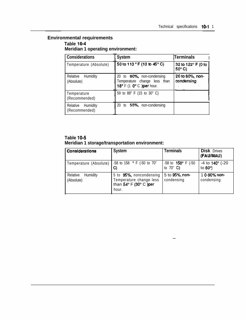
Technical specifications 10-l 1
Environmental requirementsTable 10-4Meridian 1 operating environment:
ConsiderationsTemperature (Absolute)
Relative Humidity(Absolute)
Temperature(Recommended)
Relative Humidity(Recommended) I
System 1 Terminals I
20 to 80%, non-condensingTemperature change less than18” F (1 O” C )per hour.
59 to 88” F (15 to 30” C)
20 to 55%, non-condensing
Table 10-5Meridian 1 storage/transportation environment:
Temperature (Absolute)
Relative Humidity(Absolute)
32to122”F(Oto
System Terminals Disk Drives(FAWMAU)
-58 to 158 ’ F (-50 to 70” -58 to 158” F (-50 -4 to 140° (-20C) to 70” C) to SO”)
5 to 95%, noncondensing 5 to 95%, non-. 1 O-90% non-Temperature change less condensing condensingthan 54” F (30” C )perhour.
--
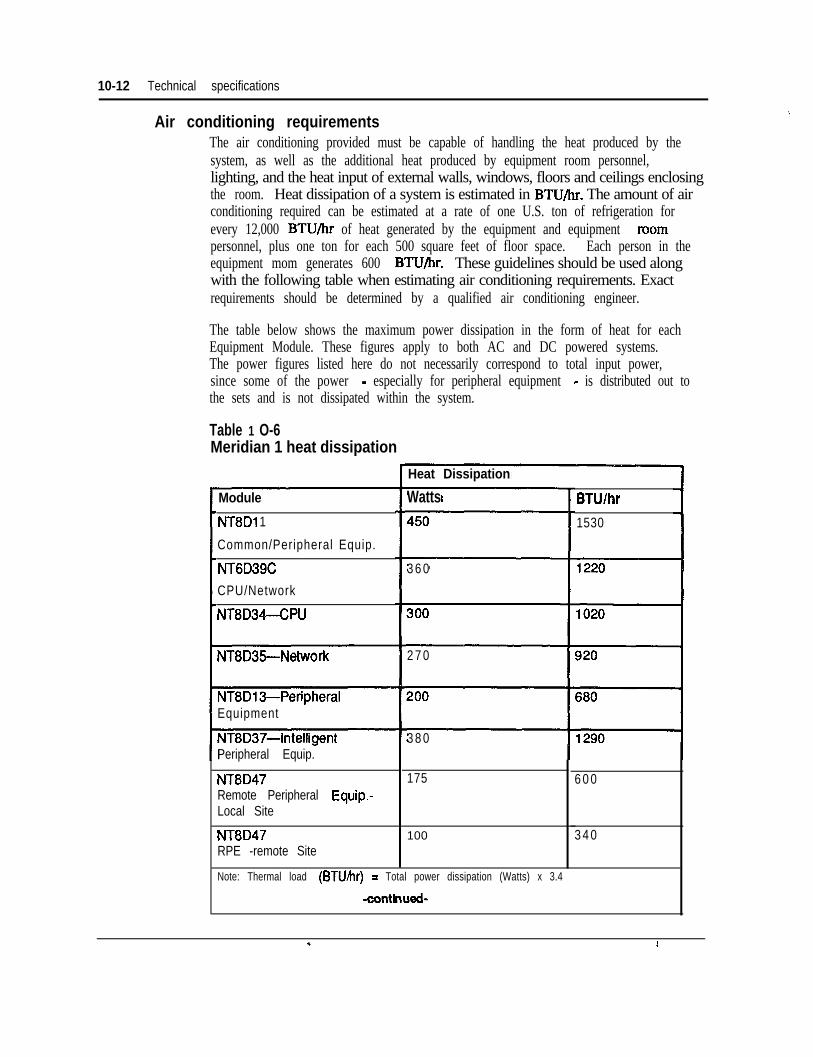
10-12 Technical specifications
Air conditioning requirementsThe air conditioning provided must be capable of handling the heat produced by thesystem, as well as the additional heat produced by equipment room personnel,lighting, and the heat input of external walls, windows, floors and ceilings enclosingthe room. Heat dissipation of a system is estimated in BTU/hr. The amount of airconditioning required can be estimated at a rate of one U.S. ton of refrigeration forevery 12,000 BTU/hr of heat generated by the equipment and equipment mompersonnel, plus one ton for each 500 square feet of floor space. Each person in theequipment mom generates 600 BTU/hr. These guidelines should be used alongwith the following table when estimating air conditioning requirements. Exactrequirements should be determined by a qualified air conditioning engineer.
The table below shows the maximum power dissipation in the form of heat for eachEquipment Module. These figures apply to both AC and DC powered systems.The power figures listed here do not necessarily correspond to total input power,since some of the power - especially for peripheral equipment - is distributed out tothe sets and is not dissipated within the system.
Table 1 O-6Meridian 1 heat dissipation
Module
NT8Di 1
Common/Peripheral Equip.
NT6D39C
CPU/Network
NT8D34-CPU
NT8D35-Network
NT8D13-PeripheralEquipment
NT8D37AntelligentPeripheral Equip.
NT8D47Remote Peripheral Equip.-Local Site
NT8D47RPE -remote Site
Heat Dissipation
Watts
3 6 0
2 7 0
3 8 0
175 6 0 0
100
BTU/h
1530
3 4 0
Note: Thermal load (BTU/hr) = Total power dissipation (Watts) x 3.4
-conthued-
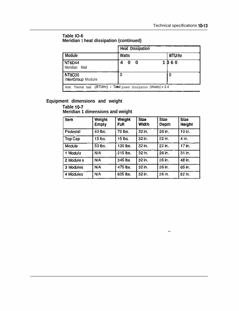
Technical specifications lo-13
Table IO-6Meridian 1 heat dissipation (continued)
ModuleNT6D44Meridian Mail
NT8D36InterGroup Module
Heat DissipationWatts 1 BTU/hr4 0 0 1 3 6 0
Note: Thermal load (BTU&v) = Tatal power d iss ipa t ion (Watts) x 3.4
Equipment dimensions and weightTable 10-7Meridian 1 dimensions and weight
--
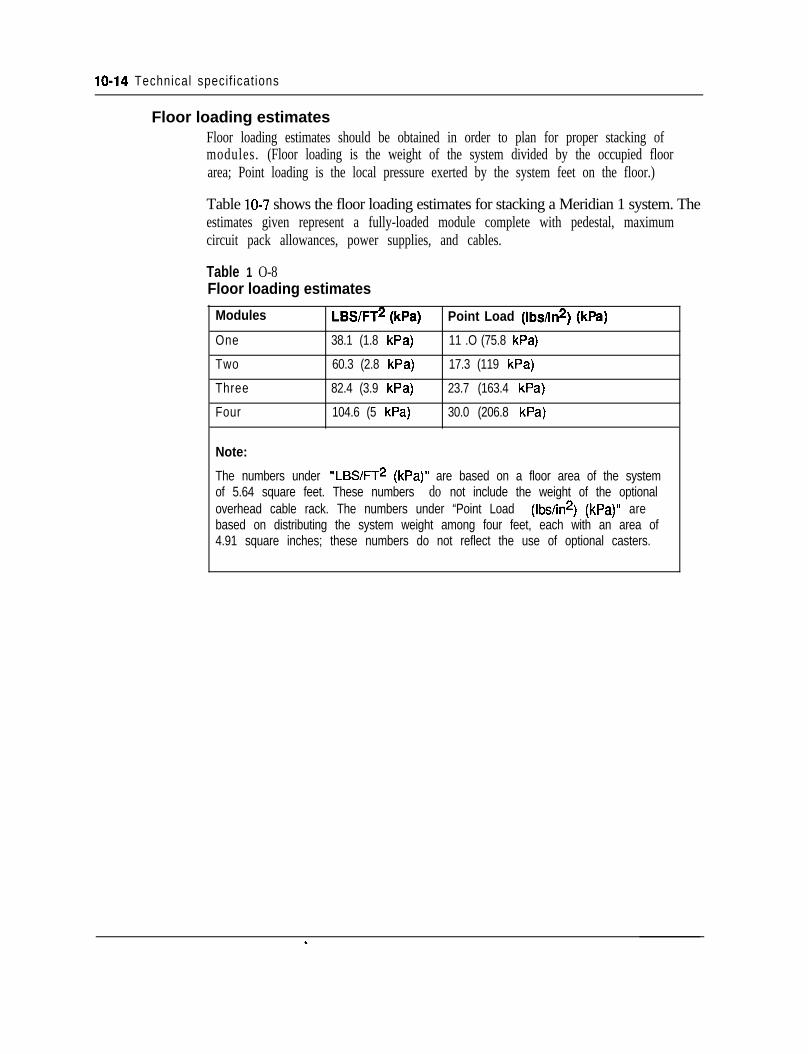
lo-14 Technical specif icat ions
Floor loading estimatesFloor loading estimates should be obtained in order to plan for proper stacking ofmodules. (Floor loading is the weight of the system divided by the occupied floorarea; Point loading is the local pressure exerted by the system feet on the floor.)
Table 10-7 shows the floor loading estimates for stacking a Meridian 1 system. Theestimates given represent a fully-loaded module complete with pedestal, maximumcircuit pack allowances, power supplies, and cables.
Table 1 O-8Floor loading estimates
Modules LBS/FT* (kPa)
One 38.1 (1.8 kPa)
Two 60.3 (2.8 kPa)
Three 82.4 (3.9 kPa)
Four 104.6 (5 kPa)
Note:
Point Load (Ibshn*) (kPa)
11 .O (75.8 kPa)
17.3 (119 kPa)
23.7 (163.4 kPa)
30.0 (206.8 kPa)
The numbers under “LBS/FT* (kPa)” are based on a floor area of the systemof 5.64 square feet. These numbers do not include the weight of the optionaloverhead cable rack. The numbers under “Point Load (Ibs/in*) (kPa)” arebased on distributing the system weight among four feet, each with an area of4.91 square inches; these numbers do not reflect the use of optional casters.
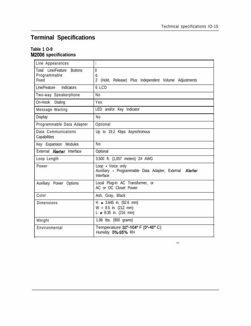
Technical specif icat ions IO-15
Terminal Specifications
Table 1 O-9M2006 specifications
Line Appearances 1
Total Line/Feature Buttons 8Programmable 6Fixed 2 (Hold, Release) Plus Independent Volume Adjustments
Line/Feature Indicators 6 LCD
Two-way Speakerphone No
On-Hook Dialing Yes
Message Waiting LED and/or Key Indicator
Display No
Programmable Data Adapter Optional
Data Communications Up to 19.2 Kbps AsynchronousCapabilities
Key Expansion Modules No
External Aletter Interface Optional
Loop Length 3,500 ft. (1,057 meters) 24 AWG
Power Loop - Voice onlyAuxiliary - Programmable Data Adapter, External AlerterInterface
Auxiliary Power Options Local Plug-in AC Transformer, orAC or DC Closet Power
Color
Dimensions
Ash, Gray, Black
H = 3.645 in. (92.6 mm)W = 8.5 in. (212 mm)L = 8.35 in. (216 mm)
Weight
Environmental
1.98 Ibs. (900 grams)
Temperature 32”-104” F (O”-40” C)Humidity 5%-95% RH
--
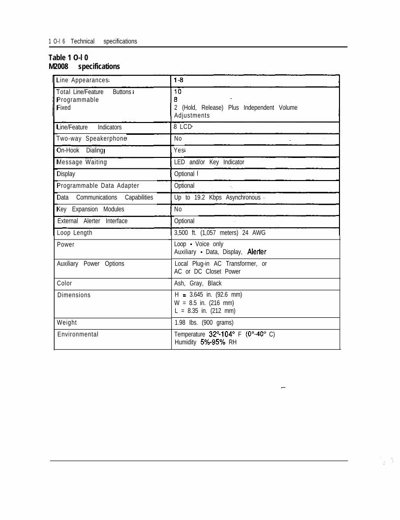
1 O-l 6 Technical specifications
Table 1 O-l 0M2008 specifications
Line Appearances
Total Line/Feature ButtonsProgrammableFixed
Line/Feature Indicators
Two-way Speakerphone
On-Hook Dialing
Message Waiting
Display
Programmable Data Adapter
Data Communications Capabilities
Key Expansion Modules
External Alerter Interface
Loop Length
Power
Auxiliary Power Options
Color
Dimensions
Weight
Environmental
2 (Hold, Release) Plus Independent VolumeAdjustments
8 LCD
No
Yes
LED and/or Key Indicator
Optional
Optional
Up to 19.2 Kbps Asynchronous
No
Optional
3,500 ft. (1,057 meters) 24 AWG
Loop - Voice onlyAuxiliary - Data, Display, Alerter
Local Plug-in AC Transformer, orAC or DC Closet Power
Ash, Gray, Black
H = 3.645 in. (92.6 mm)W = 8.5 in. (216 mm)L = 8.35 in. (212 mm)
1.98 Ibs. (900 grams)
Temperature 32”104’ F (O”-40” C)Humidity 5O-95% RH
--
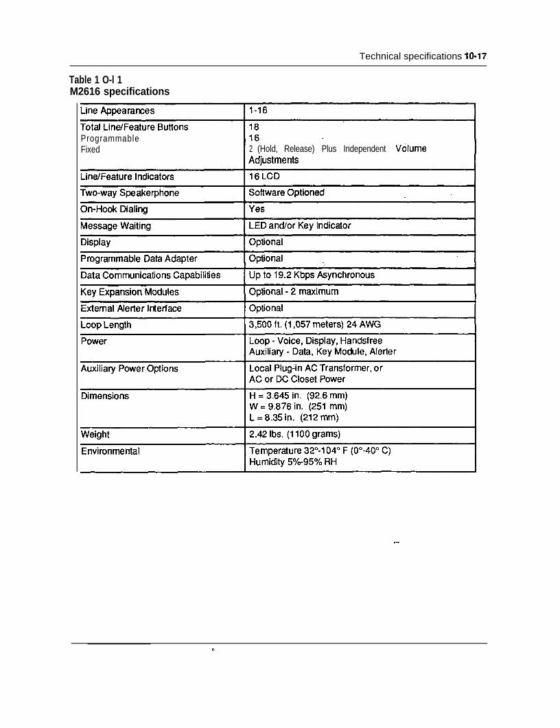
Technical specifications lo-17
Table 1 O-l 1M2616 specifications
ProgrammableFixed 2 (Hold, Release) Plus Independent Vdlume
--
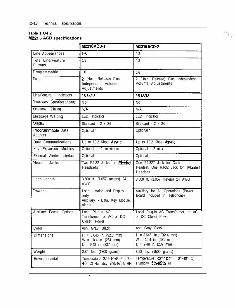
IO-18 Technical specifications
Table 1 O-l 2Iv1221 6 ACD specifications
M2216ACD-1 M2216ACD-2
Line Appearances l-6 1 8
1 8 1 8Total Line/FeatureButtons
Programmable 1 61 6
2 (Hold, Release) PlusFixed 2 (Hold, Release) Plus IndependentVolume AdjustmentsIndependent Volume
Adjustments
Line/Feature Indicators
Two-way Speakerphone N o No
On-Hook Dialing
Message Waiting
N/AN/A
LED Indicator LED Indicator
Standard - 2 x 24Standard - 2 x 24Display
PrOQrafmIabk Data Optional Optional
Up to 19.2 Kbps Async
Adapter
Data Communications Up to 19.2 Kbps Async
Optional - 2 maximumKey Expansion Modules
External Alerter Interface
Optional - 2 max
Optional Optional
Headset Jacks Two RJ-32 Jacks for ElectretHeadsets
One PJ-327 Jack for CarbonHeadset, One RJ-32 Jack for ElectretHeadset
Loop Length 3,500 ft. (1,057 meters) 24 AWG3,500 ft. (1,057 meters) 24AWG
Loop - Voice and DisplayonlyAuxiliary - Data, Key Module,Alerter
Power Auxiliary for All Operations (PowerBoard Included in Telephone)
Auxiliary Power Options Local Plug-in AC Transformer, or ACor DC Closet Power
Local Plug-in ACTransformer, or AC or DCCloset Power
Ash, Gray, BlackColor Ash, Gray, Black __
Dimensions H = 3.645 in. (92.6 mm)W = 10.4 in. (251 mm)L = 9.48 in. (237 mm)
H = 3.645 in.,(92.6 mm)W = 10.4 in. (251 mm)L = 9.48 in. (237 mm)
Weight 2.84 Ibs. (1300 grams) 3.28 Ibs. (1500 grams)
Environmental Temperature 32°-1040 F (O”-40° C) Humidity 5%-95% RH
Temperature 32”104” F(O”-40” C)Humidity 5%-95% RH
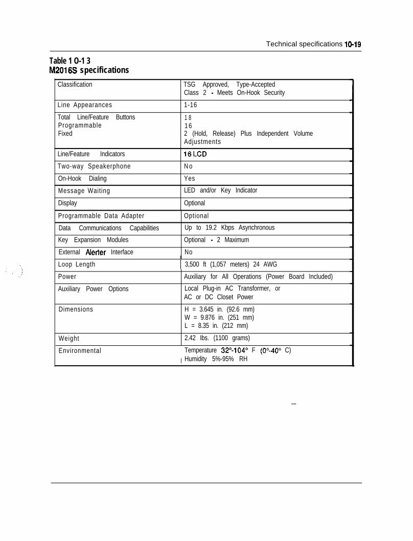
Technical specifications 10-19
Table 1 O-1 3M2016S specifications
Classification
Line Appearances
Total Line/Feature ButtonsProgrammableFixed
Line/Feature Indicators
Two-way Speakerphone
On-Hook Dialing
Message Waiting
Display
Programmable Data Adapter
Data Communications Capabilities
Key Expansion Modules
External Alerter Interface
Loop Length
Power
Auxiliary Power Options
TSG Approved, Type-AcceptedClass 2 - Meets On-Hook Security
1-16
1 81 62 (Hold, Release) Plus Independent VolumeAdjustments
16LCD
N o
Yes
LED and/or Key Indicator
Optional
Optional
Up to 19.2 Kbps Asynchronous
Optional - 2 Maximum
NoI
1 3,500 ft (1,057 meters) 24 AWG
Auxiliary for All Operations (Power Board Included)
Local Plug-in AC Transformer, orAC or DC Closet Power
Dimensions H = 3.645 in. (92.6 mm)W = 9.876 in. (251 mm)L = 8.35 in. (212 mm)
Weight 2.42 Ibs. (1100 grams)
EnvironmentalI
Temperature 32”104” F (0”40” C)Humidity 5%-95% RH
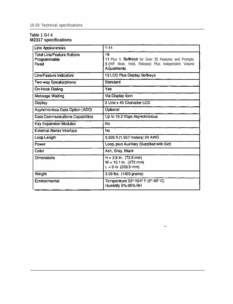
10-20 Technical specif ications
Table 1 O-l 4M2317 specifications
Plus 5 Softkeys for Over 35 Features and PromptsH/F Mute, Hold, Release) Plus Independent Volume
--
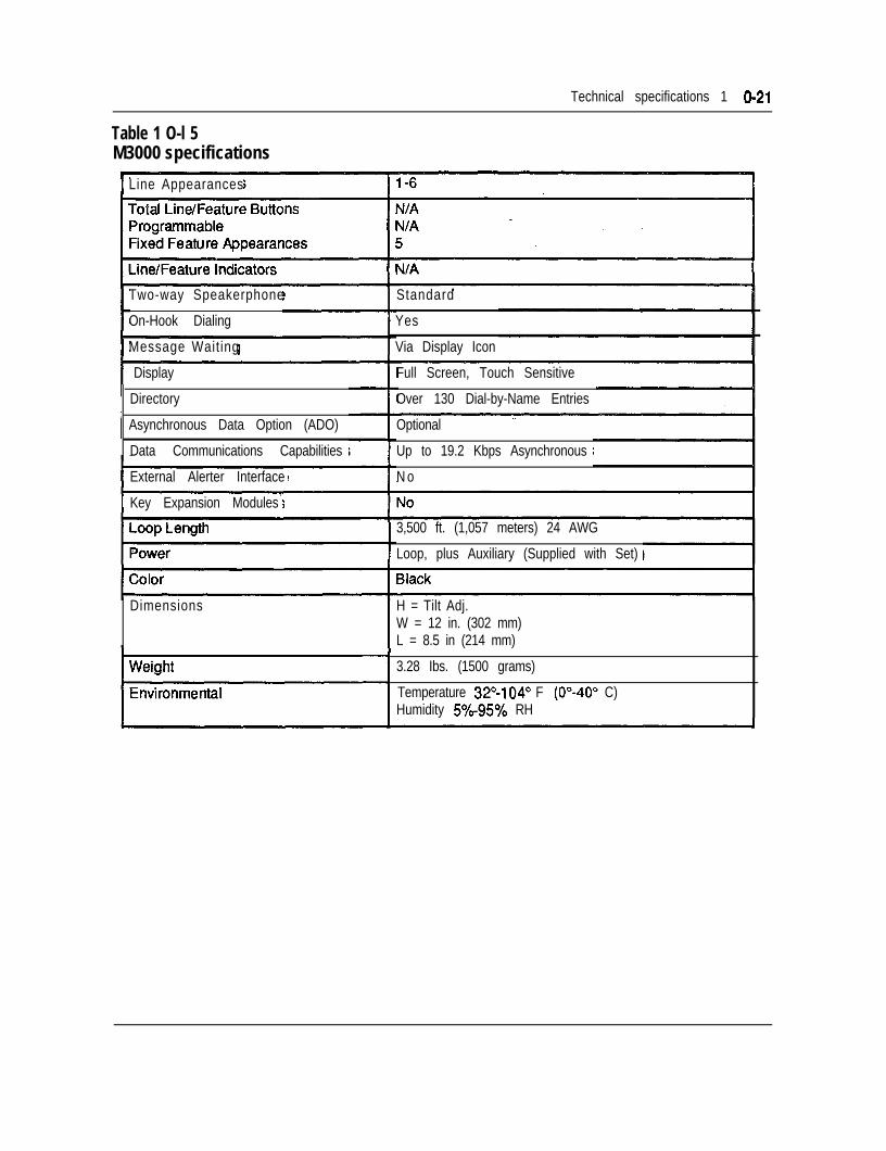
Technical specifications 1 O-21
Table 1 O-l 5M3000 specifications
1 Line Appearances
Two-way Speakerphone
On-Hook Dialing
1 Message Waiting
1 Display
Directory
Asynchronous Data Option (ADO)
Data Communications Capabilities
1 External Alerter Interface
1Key Expansion Modules
Dimensions
Standard
Yes
Via Display Icon
Full Screen, Touch Sensitive
Over 130 Dial-by-Name Entries
Optional
Up to 19.2 Kbps Asynchronous
N o
3,500 ft. (1,057 meters) 24 AWG
Loop, plus Auxiliary (Supplied with Set)
H = Tilt Adj.W = 12 in. (302 mm)L = 8.5 in (214 mm)
3.28 Ibs. (1500 grams)
1 Temperature 32”104” F (O”-40” C)Humidity 50/b-95% RH
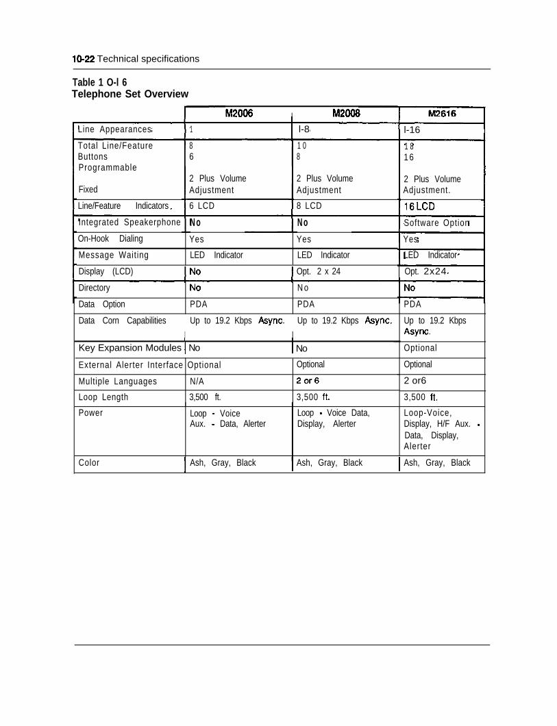
IO-22 Technical specifications
Table 1 O-l 6Telephone Set Overview
Line Appearances
M2006 I M2068
1 1 l-8
Total Line/FeatureButtonsProgrammable
Fixed
Line/Feature Indicators
Integrated Speakerphone
On-Hook Dialing
Message Waiting
N oYes
LED Indicator
86
2 Plus VolumeAdjustment
6 LCD
1 08
2 Plus VolumeAdjustment
8 LCD
N oYes
LED Indicator
l-16
1 81 6
2 Plus VolumeAdjustment.
16LCD
Software Option
Yes
LED Indicator
Display (LCD) Opt. 2 x 24 1 Opt. 2x24
Directory
Data Option PDA
N o
PDA PDA
Data Corn CapabilitiesI
Up to 19.2 Kbps Async.I
Up to 19.2 Kbps Async.
I I
Key Expansion Modules 1 No 1 No
Up to 19.2 KbpsAsync.
Optional
OptionalExternal Alerter Interface Optional
Multiple Languages N/A
Loop Length 3,500 ft.
Power Loop - VoiceAux. - Data, Alerter
Optional
2or6
3,500 ft.
Loop - Voice Data,Display, Alerter
2 or6
3,500 ft.
Loop-Voice,Display, H/F Aux. -Data, Display,Alerter
Color Ash, Gray, Black Ash, Gray, Black Ash, Gray, Black
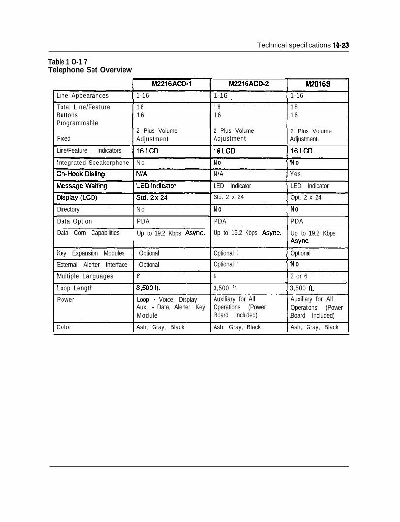
Technical specifications lo-23
Table 1 O-1 7Telephone Set Overview
I M2216ACD-1 M2216ACD-2 M2016S
Line Appearances 1-16 1-16 _ 1-16
Total Line/FeatureButtonsProgrammable
1 81 6
1 81 6
1 81 6
2 Plus VolumeAdjustment
2 Plus VolumeAdjustment.
2 Plus VolumeAdjustment
16LCD
Fixed
Line/Feature Indicators
Integrated Speakerphone 1 N o N o N oN/A
LED Indicator
Std. 2 x 24
Yes
LED Indicator
Opt. 2 x 24
Directory
Data Option
N o
PDA
N oPDA
N oPDA
Data Corn CapabilitiesI
Up to 19.2 Kbps Async. Up to 19.2 Kbps Async. Up to 19.2 KbpsAsync.
Key Expansion Modules 1 Optional Optional Optional
External Alerter Interface 1 Optional Optional N oMultiple Languages 6 6
3,500 ft.
2 or 6
3,500 ft.Loop Length
Power Loop - Voice, DisplayAux. - Data, Alerter, KeyModule
Auxiliary for AllOperations (PowerBoard Included)
Auxiliary for AllOperations (PowerBoard Included)
Ash, Gray, BlackColor Ash, Gray, Black Ash, Gray, Black
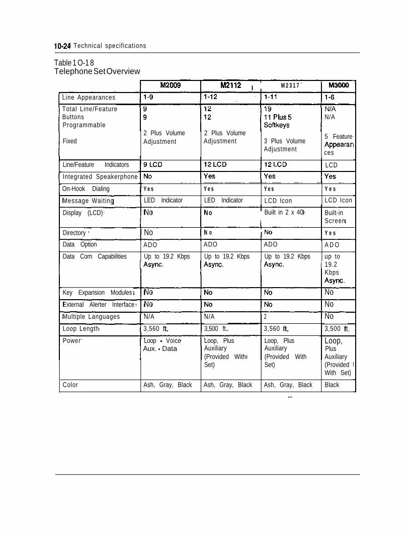
lo-24 Technical specif icat ions
Table 1 O-1 8Telephone Set Overview
ml2112 I M2317
l-6Line Appearances
Total Line/FeatureButtonsProgrammable
N/AN/A
2 Plus VolumeAdjustment
2 Plus VolumeAdjustment 3 Plus Volume
Adjustment
5 FeatureAppearances
Fixed
I I I 1
19LCD I12LCD I12LCD 1 LCDLine/Feature Indicators
Integrated Speakerphone
Yes
LED Indicator
Yes
LED Indicator
Yes
LCD Icon
Y e s
LCD Icon
On-Hook Dialing
Message Waiting
Display (LCD) No N oI
Built in 2 x 40 Built-inScreen
Directory No N o I No Y e s
ADO ADO ADO A D O
Up to 19.2 Kbps Up to 19.2 Kbps Up to 19.2 Kbps up to
Data Option
Data Corn Capabilities1 Async. 1 Async. 1 Async. 1 19.2
KbpsAsync.
No NoKey Expansion Modules
External Alerter Interface No NoMultiple Languages N/A
3,500 ft.
N/A
3,560 ft.
2
3,560 ft.
No3,500 ft.Loop Length
Power Loop - Voice~ Aux. - Data
Loop, PlusAuxiliary(Provided WithSet)
Loop,PlusAuxiliary(ProvidedWith Set)
Loop, PlusAuxiliary(Provided WithSet)
Color Ash, Gray, Black Ash, Gray, Black Ash, Gray, Black Black--
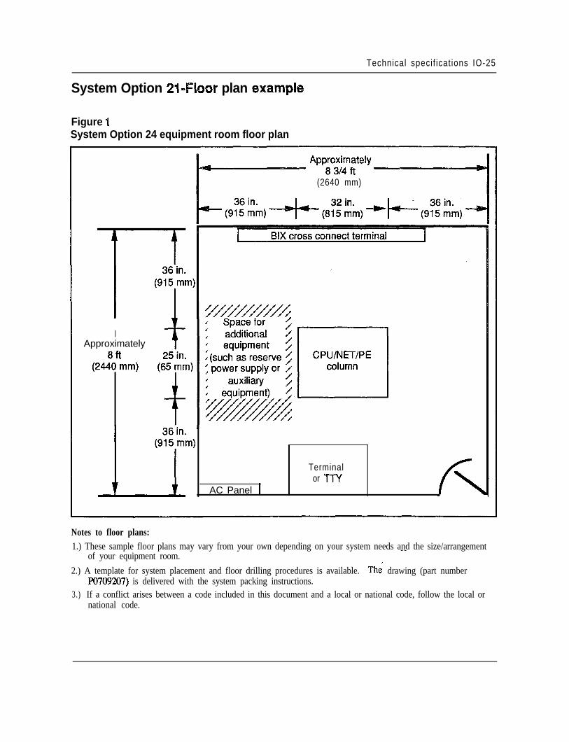
Technical specif icat ions IO-25
System Option 21-Floor plan exafmple
Figure 1System Option 24 equipment room floor plan
(2640 mm)
IApproximately
(2448d’mm)
AC Panel 1
Terminalor TTY
Notes to floor plans:1.) These sample floor plans may vary from your own depending on your system needs and the size/arrangement
of your equipment room.- -
2.) A template for system placement and floor drilling procedures is available. The drawing (part numberpO709207) is delivered with the system packing instructions.
3.) If a conflict arises between a code included in this document and a local or national code, follow the local ornational code.
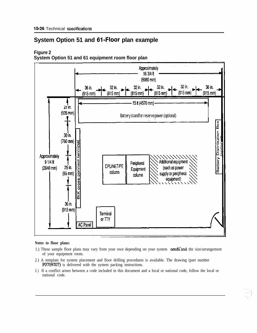
10-26 Technical wecifications
System Option 51 and 61-Floor plan example
Figure 2System Option 51 and 61 equipment room floor plan
Battery stand for reserve power (optional)
Notes to floor plans:1.) These sample floor plans may vary from your own depending on your system needs-and the size/arrangement
of your equipment room.2.) A template for system placement and floor drilling procedures is available. The drawing (part number
PO709207) is delivered with the system packing instructions.3.) If a conflict arises between a code included in this document and a local or national code, follow the local or
national code.
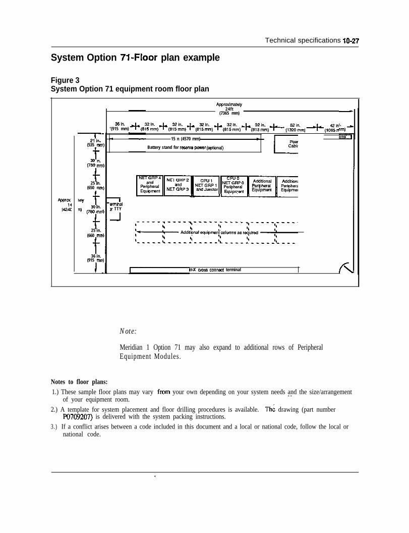
Technical specifications lo-27
System Option 71.Floor plan example
Figure 3System Option 71 equipment room floor plan
ApQrox(422
-2l(in(535 mh
t30 in.(760 mn
f25 In.
(650 mn
w t30 In.
‘) (76Omn
f25 in.
(660 mrr
t36 in.
(915 mrT
Approximately24ft
(7365 mm)
‘(915 mm)36’n. ~(6:~~,)~(6~~;,~(6~~~)~(6~~~m)~~(6~~~m)~(,~~m)4(,O~~m)-I
m 15 n (4570 mm)-
Battery stand for resofve power (cptbnal)
L
I
wminal,r TTY
-I
MX cm56 connect terminalI I
Note:
Meridian 1 Option 71 may also expand to additional rows of PeripheralEquipment Modules.
Notes to floor plans:1.) These sample floor plans may vary from your own depending on your system needs and the size/arrangement
of your equipment room. - -
2.) A template for system placement and floor drilling procedures is available. The drawing (part numberFO709207) is delivered with the system packing instructions.
3.) If a conflict arises between a code included in this document and a local or national code, follow the local ornational code.
c

--
11-1
Chapter il-List of termsAccess time
The time required to retrieve information from or store information in a computer’smemory.
Acoustic couplerA data set which converts electrical signals into audio signals suitable fortransmission over telephone circuits. The telephone handset is placed into a cradledevice that acoustically couples the transmitter and receiver in order to send orreceive the modulated signal.
AddressA number designating a location in memory.
Adjacent channelThe channel closest to the channel being used for transmission, either in physicalproximity or in electronic characteristics.
A-lawThe companding law used in PCM systems in the European countries is the A-Law,which is defined as follows:
l+ l n x 1 <xc1Y = l+lnA A
where x is the input signaly is the compressed output signalA is a constant, set to 87.6ln is the natural logrithm - -
AlgorithmA set of processes in a computer program used to solve a particular problem in afinite number of steps.
Analog signalAny voltage or current waveform that varies continuously with time.
11-2 List of terms
Analog -to-digital (A/D) converterCircuitry which changes an analog signal into a digital pulse stream.
ANSI (American National Standards Institute)The principal standards organization in the USA, formed in 1918, and run as a non-profit, non-government body supported by private industry and professionalorganizations. Its role is to coordinate voluntary standards activities.
ASCII Code (American Standard Code for Information Interchange)A binary code used to exchange information between computers.
Assembly languageA programming language in which each statement corresponds to a machinelanguage instruction. Codes are less close to everyday language than those of highlevel languages, therefore mnemonic devices are included.
AsynchronousCharacteristic of any operation that is independent of a master clock or timingsignals.
Asynchronous transmissionData transmission in which the characters may be transmitted at varying intervals orin blocks, and which uses start and stop elements at the beginning and end of eachcharacter, instead of synchronizing the whole message block.
Automatic Call Distribution (ACD)A switching system which automatically distributes incoming calls to a centralizedgroup without going through a switchboard operator. If no answering positions areavailable, the calls will be automatically held until one becomes free. Used incatalog ordering, airline information, and credit-card authorization centers of largerbusinesses.
Automatic Number Identification (ANI)The automatic line identification of outward dialed long distance calls whichpermits call completion and billing without the telephone company’s operatorintervention.
B channelThe 64-Kbps channel of a digital subscriber link (DSL) (where there are two) or anextended DSL (where there are 23) that is circuit switched and can carry eithervoice or data. Usually considered to stand for “Bearer” channel
Balancing networkElectronic circuitry used to match two-wire to four-wire toll facilities in order tomaximize power transfer and minimize echo.
List of terms 11-3
BASIC language (Beginner’s Ail-purpose Symbolic instruction Code)A simplified computer programming language based upon common Englishlanguage terms.
Basic Rate Access
Baud
Bell 103
Bell 113
Bell 201
Bell 202
Bell 208
Bell 209
Bell 212
Binary
Two 64-Kbps B channels and one 16-Kbps D channel (2B+D) over a single digitalsubscriber line.
A unit of signaling speed which measures the number of signal changes per second.If each signal element or state change represents one bit, then the baud rate equalsthe bit rate; otherwise, the two differ.
A North American Bell System modem standard which provides asynchronous datatransmission at speeds up to 300 bps.
As Bell 103, but provides either originate or answer capability only.
A North American Bell System modem standard which provides synchronous datatransmission at 2400 bps.
A North American Bell System modem standard which provides asynchronous datatransmission at 1800 bps. Requires four-wire line for full duplex operation.
A North American Bell System modem standard which provides synchronous datatransmission at 4800 bps.
A North American Bell System modem standard which provides synchronous datatransmission at 9600 bps.
A North American Bell System modem standard which provides full-duplexasynchronous or synchronous data transmission at 1200 bps on the dial network.
- -A system of numbers or codes involving only two states, typically 1 or 0.
Binary coded decimal (BCD)A coding scheme in which four bits are used to represent numbers and six bits torepresent letters and special symbols.
11-4 List of terms
Binary Synchronous Communications (BSC, “BISYNC)‘)
Binary word
Bipolar
Bisync
Bit
Bit interleaved
Bit rate
Bit stream
An IBM byte-controlled protocol using a defined set of control characters andsequences for synchronous binary coded data transmission.
A group of bits that represent one piece of information. In PCM systems, an eightbit binary word is used to represent the magnitude of an analog signal at a particularinstant in time.
Refers to two polarities, positive and negative. Digital information is normallytransmitted in alternating bipolar pulses.
Short for “Binary Synchronous Communications,” a half-duplex, character-orientedprotocol developed by IBM.
A contraction of the term “binary digit” which represents a single character in agroup, either 1 or 0.
This refers to the format of the resulting higher rate bit stream in a TDM systemwhere the higher rate bit stream is generated by taking single bits from each of thelower rate bit streams in turn.
The speed at which bit positions are transmitted, normally expressed in bits persecond.
A continuous string of bit positions occurring serially in time.
Bit stream formatIn some bit streams the bit positions, or groups of bit positions, have specific uses.The way in which the bit stream is subdivided is the format of the bit stream. Inorder to locate the position of the format within the bit stream a recurring alignmentsignal is required either internal or external to the bit stream.
Black boxA term used to describe a device which handles known input and produces knownoutput, but whose mechanism is hypothetical or unknown.
Blocking(1) A switching system condition in which no circuits are available to complete acall, and a busy signal is returned to the caller. (2) The creation of blocks fromindividual records in a computer memory file.
List of terms 1 l-5
Bootstrap routineA computer technique of inputting data before loading a program and therebyinitiating the loading of the program.
Bubble memoryA high capacity RAM memory in which a bit of information is recorded as a bubbleon a thin film of magnetic silicate, and read by an electronic reading head.
BufferA temporary storage facility used as an interface between system elements .whosedata rates are different.
BusA major electrical path used to transfer information between two or more electricalcircuits.
Busy hourThe peak hour of communications traffic in a carrier facility.
ByteThe smallest number of binary digits which is acted upon as if it were a singleentity. In most present-day systems, a byte is equivalent to 8 bits.
Byte interleavedThis refers to the format of the resulting higher rate bit stream in a TDM systemwhere the higher rate bitstream is generated by taking groups of bits (ie bytes) fromeach of the lower rate bit streams in turn.
Cable, coaxialA cable containing a central conductor insulated from a surrounding conductor, orseveral such pairs. An efficient carrier of high frequency signals, and capable ofbeing multiplexed.
Call processing programsSoftware that controls the switching network in an electronic switching system.
Carrier systemA means of producing several channels from one communications link bycombining signals at the originating end, transmitting them in a wideband or highspeed signal, and separating them at the receiver. - -
Carrler waveA signal of a certain frequency and amplitude which can be modulated with respectto amplitude, frequency and phase, and transmitted as a data signal.
CCITTComite Consultatif International Telegraphique et Telephonique. An internationalcommittee that sets telephone, telegraph, and data communications standards.

11-6 List of terms
CCITT #7 signalingThe standard for signalling within telecommunications networks being developedby CCITT. It will eventually replace the CCIS6 network in the U.S. Usuallyreferred to as SS7.
cm-r v.21
CCll-r v.22
CCI-IT V.23
Ccl-IT V.24
CCITT V.25
CCllT V.26
CCITT V.27
CCITT V.28
CCITT v.29
CCITT X.25
c c s
Standards for modems operating asynchronously at 200-300 bps, full-duplex, on thedial network (similar to Bell 103).
Standards for synchronous half-duplex modems operating on the dial network at1200 bps (similar to Bell 212A).
Standards for asynchronous half-duplex modems on the dial network, and full-duplex on a leased four-wire line, operating at 600 or 1200 bps.
Recommendation for interchange circuits between data communications equipmentand terminals (similar to RS-232C).
Recommendation defining a packet switching network protocol.
Standards for modems operating at 2400/1200 bps, half-duplex on the dial network,and full-duplex on a leased four-wire line (similar to Bell 201).
As V.26, but at 4800 bps on leased telephone-type circuits (similar to Bell 208).
Recommendation for the electrical characteristics for unbalanced double-currentinterchange circuits operating at data signaling rates below the limit of 20,000 bps(Geneva 1972).
Standards for synchronous modems operating at 96000 bps on a leased four-wireline (similar to Bell 209).
- -
Recommendation defining a packet switching networks protocol.
A communications unit of traffic measurement equivalent to 100 call-seconds, sothat there are 36 CCS in one hour.
List of terms 11-7
Central Processing Unit (CPU)The portion of a computer which controls its operation and manipulates the databeing processed.
CentrexA private exchange service permitting incoming calls to be dialed direct toextensions, without operator intervention. Usually provided from the telephonecompany’s central office facilities.
ChannelA signal pathway in a communications system between two or more points,furnished by a wire, radio, light fibers, satellite or a combination thereof.
Channel bankAn electronic device used to digitally encode analog signals and time divisionmultiplex the resultant digital signals and also demultiplex and decode these digitalsignals.
CharacterAn actual or coded representation of a letter, number or symbol.
ChipA small (1-5 cm) integrated circuit of several elements with external connections toother electronic circuits.
CircuitA complete transmission path to and from two points in a communications system.
Circuit switchingA method of communications in which individual circuits are connected to establisha continuous connection for the use of stations on the circuit until it is disconnected.
Class Of Service (COS)The type of service in use by a subscriber of a communications system, includingthe type of telephone equipment, and the calling privileges or restrictions.
Clear-to-send delayThe time required for a data set to inform a terminal that it is ready to send or reply.(Also called modem turnaround.)
Clock --
A device that generates periodic signals used for system synchronization.
ClusterA group of terminals connected to a communications facility by a cluster controllerso that they may operate together.
11-8 List of terms\::,
COBOL (Common Business Oriented Language)A high level programming language used for business data manipulation.
;”
CodeThe representation of an alphanumeric character or symbol in machine language
Code conversionThe translation from one code to another (e.g., ASCII to Baudot), so that machinesusing different codes may communicate with each other.
CODEC (Coder/Decoder)A device used to convert analog voltage samples into binary coded digital data andvice versa. A codec encodes analog signals into 8 bit, u = 255, PCM. It alsoperforms the reverse function of decoding PCM signals into analog signals.
Common channel signalingA technique in which signaling information relating to several circuits is conveyedby addressed messages over a single signaling channel.
Common Channel lnteroff ice Signaling (CCIS)A method where all signaling data is sent over a dedicated connection between theprocessors of two switching systems. Signaling and transmission are completelysegregated and handled over separate facilities.
Common controlEquipment which receives and stores subscriber-dialed information for subsequentprocessing.
,’
Communications terminalAny device which produces tones or electrical signals which can be transmitted overa communications facility.
CompandlngThe process of compressing quantized speech samples at low speech amplitudes atthe transmitting end of a system and then expanding these levels at the receivingend, thus reducing quantizing distortion.
Companding lawMany different algorithms (i.e. companding laws) could be used to obtaincompanding effects. Two companding laws in widespread use in PCM systems arethe “MU-Law” and the “A-Law”. The MU-Law is used in North America and theA-Law is used in European countries.
CompilerA computer program used to convert symbols meaningful to a human operator tocodes meaningful to a specific computer.
List of terms II-9
ConcentratorA device used in data communications which can subdivide a channel into a largersystem of data routes to permit the transfer of more data than would otherwise bepossible. Low speed buffered asynchronous channels are fed into a high speedsynchronous channel via a concentrator, which creates several channels of lowerspeed.
ConditioningThe improvement of standards of a data transmission line in order to increase thedata rate and decrease the error rate.
ContentionA method of communications line control in which users compete for transmissiontime on a first-come, first-served basis, and must wait until a channel is free.
Continuity checkA check made of a communications link to ensure that a proper data connectionexists.
Control characterA character included with a data communications signal to control and facilitatetransmission. Examples are CR (carnage return), EOT (end of text), ACK(acknowledgment), STX (start of text).
Conversation modeAn on-line dialogue between a terminal and a computer in which each responds todata presented by the other on a character-by-character basis.
Conversation timeThe portion of time used in a call devoted to actual data or speech transmission asopposed to that used for call connection and coordination.
ConverterA peripheral device which converts data from one medium or mode to another; e.g.,paper tape to magnetic disc.
CPE-customer premise equipmentThe generalized term for any equipment that resides on the end user’s side of thenetwork interface boundary.
Crosstalk --
Interference on a “disturbed” circuit caused by the transfer of energy from a nearby“disturbing” circuit.
CRT-cathode ray tubeAn electronic display screen similar to a television picture tube.
11-10 List of terms
CSA-Canadian Standard Association
Cursor
Cycle time
D channel
Data
Data base
A Standards Council of Canada body which sets electric and electronic standardsincluding those applicable to data communications.
An illuminated marker on a visual display unit which shows the position of the nextcharacter to be generated, and which can be moved about the screen to perform textcontrol operations.
The shortest period of time necessary to complete one computer instruction.
The packet-switched channel on a DSL (where it is 16 Kbps) or an EDSL (where itis 64 Kbps) that carries signaling messages and packet-switched user data. Usuallyconsidered to stand for “Delta” or Data channel.
Any set of characters which can represent a meaningful message and which can betransmitted electronically.
(1) Specific information pertaining to a particular office such as subscriber directorynumbers, trunk routes, etc. This information is utilized by the generic program. (2)A set of data which can be stored for computer access.
Data communicationsThe transmission of data over electronic communications channels, often involvingtwo-way data exchange over long distances.
Data compressionThe use of special coding devices to reduce the size of data elements in order toreduce the storage space, increase channel bandwidth, or reduce cost and timerequired to transmit data.
Data couplerA device which allows a subscriber’s data set to interface with the telephonenetwork by controlling signaling functions and limiting the power applied to theline.
Data link --The hardware in a data terminal which establishes protocols and a data link withanother data terminal.
DATAPAC networkA common user packet switched commercial network which links TELENET in theUSA with the Trans-Canada Telephone Network in Canada.
List of terms 11-11
Data set(1) A device which interfaces a data terminal and a data communications facility,and which may modulate or demodulate the signal (see modem), and performcontrol functions.
(2) A collection of related data records stored in a computer.
Data stationThe hardware making up a data station, including the data terminal and circuitterminating equipment.
Data terminal equipment (DTE)Any equipment defining the beginning or end of a data link, and which usuallycomprises the data source and data sink.
DC signalingTransmission of data over physical wires using DC pulses at speeds below 150baud.
Decibel (db)A unit of signal strength relative to a standard (usually 1 milliwatt). In acoustics, ameasure of sound intensity: 1 db is the smallest amplitude difference the human earcan detect.
DecodeTo convert received PCM code words into pulse amplitude modulated pulses whichare the same as the quantized samples at the transmitting end.
Dedicated accessA direct connection between a terminal and either a service, network, or a computer.
Dedicated data channelA communications channel assigned for a subscriber’s exclusive use.
Default optionAn assumption which a computer system is programmed to make unless an alternateinstruction is given it by a user.
DegradationThe deterioration of the qualities of a signal or system.
- -Delay, absolute
The time taken for a signal to travel a certain distance in a communication system,dependent on the frequency, distance, and physical medium of transmission.
Delay distortionDistortion of a signal produced by the unequal transmission speeds of differentfrequencies of that signal in a communications medium.
11-12 List of terms
Delta modulationA method of digitally encoding an analog waveform that looks at the difference inmagnitude between successive analog signal samples. Only one quantizing level isavailable so only one bit is needed to record whether the signal went up or down.This system is simple to implement but requires a faster sampling than the NyquistFrequency.
.’ : ,i’
DemodulationThe process of retrieving an original signal from a modulated carrier wave.
DiagnosticRelating to test programs used for error and fault detection in the functioning ofhardware or software.
Digital Multiplex Switching System (DMS)Switching systems which permit digital switched transmission circuits for voice anddata. They use pulse code modulation and time division multiplexing to allowdirect switching of PCM signals without modulation into an analog form.
Digital padA device that introduces loss in an analog signal that is digitally encoded.
Digital signalA series of pulses or rapidly changing voltage levels that vary in discrete steps orincrements.
Digital-to-analog (D/A) converterCircuitry which changes digitally encoded data into an analog signal.
Digital transmission systemThe transmission of data in digital pulses which can be regenerated along the line,as opposed to analog transmission, in which waveform signals are transmitted viaamplifiers in the line.
DigitizeThe conversion of a continuous analog signal to digital form.
Disk, magneticA high capacity circular plate of varying size with a magnetic surface divided intoaddressable sectors used for Random Access Memory storage. Read/write headsenter and access data on each sector, permitting rapid access to data. Disctechnology is rapidly producing discs of different types (including the mini-floppy,floppy, flippy and hard), with increasing memory capacity.
Display unitA terminal device which produces a visual display of data. Usually a CRT display,but may be liquid crystal or other electronic medium (as opposed to hard copyprintouts of data).
:-.*, :
List of terms 11-13
DistortionThe undesirable change of signal characteristics during transmission due to distanceeffects, noise, or interference.
Down-line loadThe loading of software programs into a computer from aremote device orcomputer using a communications channel.
DowntimeThe time period during which a device or system is not functioning properly.
DriveA device which accepts a magnetic storage medium and transfers its contents uponrequest to the terminal.
DropThe external wire between a subscriber’s premises and the telephone distributioncable.
DSOThe common terminology for a single, 64-Kbps voice channel.
DSIThe common terminology for a T-carrier that multiplexes 24 channels into a single,1.544-Megabit bit stream.
DSL-digital subscriber lineThe ISDN DSL combines two B channels and one D channel on a single line. Alsocalled the basic access rate.
Dumb terminalA keyboard and display unit with no processing capability of memory storage of itsown, until connected to a computer.
DumpThe process of copying the data contents of an internal storage device into anexternal device.
EchoThe .reflection of a signal from the terminating end back along the line, causinginterference in voice signals. It can be suppressednormally non-distorting of data signals.
for voice transmission, but is
EDSL-extended digital subscriber lineThe ISDN EDSL combines 23 B channels and one D channel on a single line. Alsocalled the primary access rate.
1 l-14 List of terms
EIA (Electronic Industries Association)a US manufacturers’ group which sets electronic equipment standards.
Electronic switching system (ESS)A digital switching system controlled by computer, able to provide custom servicessuch as three way calling, speed dialing, and call transfer..
EmulatorHardware and/or software which allows a system or device to operate as if it hadproperties which it does not have, and thus interface with devices having thoseproperties. For example, an 8-bit microprocessor may emulate the features of a 16bit processor, and thus be able to accept 16-bit data from a true 16-bit device.
EncodeTo convert quantized samples into PCM words.
EncryptionThe security coding of a message to prevent unauthorized interception duringtransmission.
EPROM (erasable programmable read-only memory)ROM which can be programmed, erased, and reprogrammed.
EqualizationAn electronic technique used in telecommunications to compensate for distortionpresent on a channel, causing uneven frequency response.
Error detection and correctionMethods used in data transmission to allow the receiver to detect errors in datareceived, to request retransmission, or, in some cases, to correct it at the receivingend.
Error rateThe frequency of errors in data transmission. The rate depends on several variables,including the type of circuit, channel, or switching network the data passes through.
ExclusionThe ability of a user on some telephone systems to exclude all other users from aline or channel.
Facility --A transmission link between two or more points without-either terminating orsignaling equipment. A link with such equipment would be either a channel, centraloffice, or trunk.
FacsimileA representation of an image transmitted over a telecommunications link. Anelectro-mechanical scanning device converts the image (photo, document, graph)
List of terms 11-15
into an electrical signal which is transmitted over either an analog or digital facilityand reconstituted by the receiving equipment as an image on paper on film.
Failure rateThe number of failures which occur during a given period of time.
FeedbackThe return of part of a machine’s output to its input. It is used to control the outputby comparison with the input, or for re-entry into another phase of processing.
FEP-front-end processorAn FEP sits between a host computer and the terminals (or cluster controllers) towhich it is connected. It performs the multiplexing function that allows many datacommunication lines to access a single host computer port.
Fiber optice transmission system (FOTS)A transmission system in which light from lasers or LEDs is modulated andtransmitted over very thin glass fibers and read by photodiodes in the receiver.FOTS is capable of data rates a thousand times that of copper wire, with very lowinterference effects.
Field effect transistor (FET)A small, low-power, high input impedance semiconductor used to replace vacuumtubes in most applications, especially small circuitry.
File
Filter
Any organization collection of data, itemized, structured and stored for convenientaccess.
An electronic circuit used in telecommunications which blocks frequencies aboveand below a specified bandwidth (“band-pass”) but lets other frequencies passundisturbed.
FirmwareA program written into a non-erasable computer storage location (ROM) to preventaccidental loss, and to avoid the necessity of repeated loading of the program intoRAM.
Floppy diskA thin, flexible, flat circular plate used to store information--
FORTRAN (Formula Translation)A high level computer programming language used for mathematical and scientificapplications.
1 l-1 6 List of terms
Frame(1) A string of bits running across the width of paper or magnetic tape, representingone character. (2) In Videotex, a 24-line, 40 character screen fulI of data. (3) Intelecommunications, an information identification structure used by receivers. Agroup of digits is framed so as to be treated as one information unit.
Framing bitA bit which signals the beginning and/or end of a data unit in data communications,and allows the terminals to synchronize transmission and reception of data bits.
Framing patternA particular arrangement of framing bits.
Frequency divsion multiplexing (FDM)The division of a channel bandwidth into several smaller bandwidths, each of whichbecomes a separate data channel.
Frequency modulationThe modification of a single frequency carrier wave so that changes in its frequencycorrespond to variations of an information signal.
Frequency shift keying (FSK)
Front end
Function keys
Gain
Gate
A form of frequency modulation in which frequency values are assigned torepresent a “0” and a “l”, and in which the carrier wave shifts frequency betweenthese values according to the data.
An input device to a computer or other system which is used to enter data andcontrol codes.
Special keys on a computer keyboard which initiate system or control commands,rather than text input.
The increase in strength of a signal (in db) when it is amplified.
An electronic switch, basic to computers, which recognizes only two possible states,and will pass a signal into one of them (“off’ or “on”, “0” or “1”).
- -Gateway
(1) Equipment which allows terminals on one communications network to accessterminals or data on another network. (2) A Videotex software package whichallows Viewdata users to access data on external networks.
List of terms 11-17
GlobalA term used in computer software to indicate a complete application of a routine todata available. Thus “global search” indicates that a search routine will go throughall relevant data in storage.
Grade of serviceA measure of the circuits available for calls in a communications service at the peakhour. Calculated in calls blocked or average delay.
Graphic display terminal (GDT)A visual computer display capable of presenting graphic material such as charts,diagrams or line drawings.
HandshakingInitial signaling between two data sets on a data communications link which sets upcommunication between them.
Hard copyAny system information printed in some permanent form.
HardwareThe mechanical parts of a computer or business machine, including the electronicwiring and storage components, but excluding the software programs (seefirmware).
HDLC (high-level data link control)An International Standards Organization bit-oriented communications protocolwhich includes frame error checking sequences, start-up and shut-down procedures.
HeadA device which reads and writes data on a storage unit.
HeaderThe initial string of codes in some data communication systems which informs thereceiver of the type of data to follow and its address.
High-level languageA computer program language whose statements are translated into more than onemachine instruction. Examples include BASIC, FORTRAN, PASCAL, ALGOL,and SL-1.
- -High speed
(1) Data communication rates over 9600 bps (the limit of most voice gradechannels).
(2) A printer which runs fast enough to print as data becomes available to thecomputer.
11-18 List of terms
High speed multiplex linkA transmission circuit between two multiplexers or a terminal and a multiplexer,capable of carrying several user signals which can be separated at the receiving end.
HighwayA transmission path capable of carrying multiplexed data.
HostA large, centralized computer holding a database to which access can be supplied tousers on a subscription basis.
Hybrid circuitA complex circuit built up on film using integrated circuitry, transistors, resistorsand capacitors.
ImpedanceThe opposition of a circuit to the flow of electricity. The sum of resistance andreactance (a resistance effect caused by inductance).
Impulse noiseShort-lived, high-amplitude interference bursts on a communications channelcaused by lightning, sparking machinery or switch contacts.
InformationData which has been processed according to accepted conventions so that it ismeaningful to a user.
Information bitA bit which carries text information, generated by the data source, and not used fortransmission control purposes.
In-house system tA data communications network operated by one organization for its own needs,usually on its own premises, and without the use of common carrier facilities.
InstructionA written statement, or the equivalent computer-acceptable code, that tells thecomputer to execute a specified single operation.
Integrated circuitA functional circuit whose components and interconnecting “leads” are formed on asingle chip of semiconductor material.
Integrated Services Digital Network (ISDN)A network, generally evolving from the existing telephony digital network, thatprovides end-to-end digital connectivity to support a wide range of voice and non-voice services to which users have access via a set of standard multipurpose user tonetwork interfaces.
Intelligent terminal
List of terms 11-19
Interactive
Interface
Interference
Interrupt
A terminal containing internal storage and a CPU, capable of performing operationson data without connection to an external computer.
A system in which input elicits a response-from a computer in real time, and inwhich the computer may ask for further input from the user.
The connection between two systems. Usually, the hardware and softwareconnecting a computer terminal with peripherals such as data sets, printers, etc..
Loss of clarity of a communications signal caused by unwanted noise signals.
The pause of a computer operation initiated either by commands in the program it isusing, or by conditions which arise in the hardware (“priority interrupt”). Somespecified operation must be performed during the interrupt before the originaloperation may be resumed.
I/O buffer (Input/output)A short-term storage for computer input and output.
l/O device (Input/output)An interface between a computer or switching system and the outside world.
l-series recommendationsCCITI recommendations on standards for ISDN services, ISDN networks, user-network interfaces, and internetwork and maintenance principles.
IS0 (International Standards Organization)A body concerned with international computer and communications standards.
JitterThe phase shift effect on a digital signal caused by transmission facility delays
Key system (telephone)A multi-key telephone system on subscriber premises permitting several users toplace calls on several lines.
--LAN-local area network
A high-volume data transmission facility interconnecting a number of data devices,generally within a building or campus.
LanguageThe set of symbols, rules and conventions used to convey information, either at thehuman level or the computer level.
1 l-20 List of terms
Large scale integration (LSI)Large functional circuits made up of hundreds of gate circuits which form acomplete system or instrument. Examples are memories, computers and certaininstruments.
Laser communicationsThe use of a coherent, single-frequency, high-energy beam of light which can bemodulated to transmit information.
LCD (Liquid Crystal Display)A form of visual data display using liquid crystals which can be-electronicailychanged from a transparent to an opaque state.
Leased lineAn unswitched telecommunications channel linking two or more points inside thesame exchange, leased to subscribers for their exclusive use.
LED (Llght Emitting Diode)An electrical switching device which emits light when current is applied, and isused for some visual displays.
Level(1) The amplitude of a signal. (2) The number of bits required by a code to representone character. (3) The number of discrete signal elements in a modulation system.(4) A procedure set in a communications protocol which enables higher-levelsignaling.
Limited Distance Data Set (LDDS)A data set used for transmission over short distances (30 miles).
LineA communications iii, channel, circuit, trunk or facility. Usually refers to atelephone link between the local switching equipment and the network.
Line speedThe rate at which data signals may be passed over a particular channel, measured inbaud or bits per second.
Link(1) A circuit or path joining two communications channels in a network. (2) A lineconnector in a common control telephone switching system. --
Loading, cableThe addition of inductance through load coils along a cable to reduce amplitudedistortion and improve frequency response. The loading restores capacitancebalance to cable conductors, but is not used for high speed data channels.
List of terms 11-21
Logic circuitAn electronic element which takes a series of inputs and produces outputs accordingto the specific function the element is designed to perform.
Loopback testA circuit fault-testing procedure in which a-signal is sent from a,point on the line toa data set and back to the test point.
Low speedData communications below 2400 bps.
LSI (Large Scale Integration)An LSI circuit is a complex electronic circuit (thousands of transistors) reproducedon a silicon chip.
Machine languageCoded information consisting of binary digits that can be accepted and utilized bythe computer.
Main distributing frameThe cable rack used to terminate all distribution and trunk cables in a central officeor PBX.
MainframeA large computer with peripherals, software and database maintained by largecorporations for internal use and subscriber access.
MatrixAn orderly array of elements used to switch calls from one part of the system toanother.
Matrix prlnterAn impact printer for hard copy output which uses an array of steel pins to createthe shape of a character in dots.
Mean Time Between Failures (MTBF)The average trouble-free working period for a system or device, calculatedstatistically over time.
Mean Time to Repair (MTTR)The average time elapsed between the discovery of a fault and its correction.
Medium Scale Integration (MSI)Functional circuitry consisting of 12 or more gates which form a completefunctional operating unit such as a decoder, counter or multiplexer.
11-22 List of terms
Medium speedData communications generally between the rates of 2400 and 9600 bps on a voicegrade channel.
MemoryAn organized collection of storage elements into which units of informationconsisting of binary digits can be stored and from which this information can belater retrieved.
MessageA communication prepared for telecommunications consisting of control signals,header, start and end of text indicators, and text.
Message switchingA method of “Store-and-Forward” switching in telecommunications. A message isreceived somewhere in the network, stored, and retransmitted down the line when asuitable channel is free.
Metal Oxide Semiconductor (MOS)A type of small, field-effect transistor.
MicroA Greek prefix used to mean “very small”, as in microcomputer, or “one-millionthof a unit” as in microsecond.
MicrocomputerAn electronic device consisting of a microprocessor, program memory, datamemory, and input-output circuitry capable of accepting, storing and arithmeticallymanipulating data.
MicroprocessorAn electronic circuit contained on a single chip of silicon which performs thearithmetic logic and control operations of a digital microcomputer.
MicrowaveA high-capacity, low interference transmission network using high-frequency radiobandwidths transmitted via relay towers.
MinicomputerAn intermediate-sized computer usually capable of multi-terminal networking.
- -Mnemonic
An abbreviation or arrangement of symbols which stands for a particular instructionor process.
List of terms 11-23
Mnemonic codingAny coding system using parts of the vernacular spoken language to aidunderstanding and recall of its codes. E.g., ED for edit, EXT for end of text, DVfor divide, etc.
ModemA Modulator-DEModulator: a data set which can convert analog signals to digitalor vice-versa.
Modem poolingThe pooling of modems so that there need not be a one-to-one correspondence with“casual” terminal users, thereby reducing data service costs.
ModulationThe process by which some characteristic of a high frequency carrier signal, such asfrequency, phase or amplitude, is varied by a low frequency information signal.
Multidrop lineA single communications link connecting several terminals, and which supportspolling and selecting operations.
MultiplexerA device which enables the passage of several signals along one path, either throughtime or frequency division of the signals.
NarrowbandA communications bandwidth less than that of a voice grade circuit (normally lessthan 300 Hz) used for communication at 300 bps or less.
Network Channel Terminating Equipment (NCTE)Generic name for equipment that provides line transmission termination from anetwork to the customer’s premises.
NetworkA set of communications points interconnected by communications channels.
Network termination 1 (NTi)The CCITI’ name for ISDN NCIE. Provides the functions of line transmissiontermination and layer- 1 maintenance and multiplexing, terminating a two-wire Uinterface.
- -Network termination 1,2 (NT12)
A single piece of equipment that provides the combined functions of NT1 and NT2.
Network termination 2 (NT2)Terminates the four-wire T interface. Examples are a PBX, LAN, and terminalcontroller.
11-24 List of terms
NodeA convergent point in a communications network where lines from many sourcesmeet, and may be switched. In Datapac, a node is a packet switch location.
..,’
Non-volatile memoryA storage element whose contents are not destroyed if po.wer is lost.
Nyquist frequencyIn order to adequately reproduce an analog waveform a sampling frequency of atleast twice the maximum analog waveform frequency must be used. The minimumacceptable sampling frequency (ie. twice highest waveform fre-quency) is termed theNyquist Frequency.
Off-line
On-line
Referring to circuitry or devices not under direct control of the operating systems.
Referring to circuitry or devices in direct connection to, or under direct control of,the operating system.
Open Systems Interconnection reference model (0%)Established by the International Standards Organization (ISO), the model describesseven functional layers that define how interconnected telecommunications systemsshould interface. The seven layers are: 1) physical, 2) data link, 3) network, 4)transport, 5) session, 6) presentation, and 7) application.
Operating system (OS)Computer software which permits the control and use of all particular programs fedinto the computer, coordinates storage and recall functions, and supervises remoteterminal interaction.
Overload levelThe highest amplitude of an analog signal for which a KM code word exists.
PacketA data block with its own address and control signals transmitted as a unit through atelecommunications system.
Packet Assembler/Disassembler (PAD)Devices which provide packet assembly and disassembly capability to non-packet-mode terminals. - -
Packet switched data transmission serviceA service which transmits data in packets, including packet assembly anddisassembly, if required.
c
List of terms 11-25
Packet switchingThe routing of message packets through a network as channels are available. Eachchannel is busy for the duration of only one packet, then becomes free for anotherpacket. Packets of one message take different routes, determined by the networkitself, and are rejoined and resequenced at the destination.
Packet terminalA terminal which can communicate with a packet network, such as X.25.
Parallel transmissionThe simultaneous transmission of bits of one data character using several links, ormultiplexed channels in one link.
Parity bitA binary digit 1 added to an information word to make the total number of 1 bitseither always odd or always even. This permits checking the accuracy ofinformation transfers.
PasswordA set of characters which must be input to a system before the security program willallow access to data and operations.
PCM wordAn 8-bit code group representing a specific quantized level.
PortAn access to a switching system.
Port concentrationA device which permits several terminals to share a single port.
Primary Rate AccessTwenty-three 64-Kbps B channels and one 64-Kbps D channel (23B+D) over anextended digital subscriber line.
ProgramStep-by-step instructions that tell a computer what operations to perform.
Program memoryThe data storage area of a computer which contains the instructions that tell thecomputer what operations to perform. - -
PROM (Programmable Read-Only Memory)A permanent data storage system which holds information which can be repeatedlyread but altered only through a programming operation.
Protocol converterA device which can convert one communications protocol into another.
11-26 List of terms
Public data networkA data transmission network operated by a private telecommunicationsadministration specifically for public subscription and use.
PulseA very short-lived electric current. Usually; a DC signal burst used for digital datatransmission.
Pulse Amplitude Modulation (PAM)A time division modulation technique in which signal intelligence is represented bya pulse whose amplitude represents the amplitude of the modulating wave at aspecific instant of time.
Pulse code modulationThe most common technique used to digitize analog voice signals. Individuallysampled segments of a voice signal are coded into eight-bit digital words fortransmission.
Pulse modulationThe modulation of the amplitude (PAM), duration (PDM) or position (PPM) ofpulses to create a digital data signal. Pulse Code Modulation (PCM) samplesanalog signals at short intervals and converts this information into a digitizedinformation signal.
QuantizingThe process of dividing a sampled analog signal into discrete levels. In a PCMsystem, a finite number of bits are available for encoding each PAM sample. Thisestablishes the number of different magnitudes, or levels, that can be encoded. Forexample, 8 bit PCM has 256 possible codes, each code representing a specific signallevel. Each PAM sample is assigned the encoded value of the nearest level to it.This “rounding off’ to the nearest level is termed quantizing.
RAM (Random Access Memory)A volatile storage system in which any storage location can be read from or writtento, independent of the last storage location accessed.
ROM (Read Only Memory)A permanent storage system manufactured with predetermined data content, to beread but not altered during computer operation.
Real time --The actual time in which a process or event takes place. In computer processing,the running of an input/process/output cycle during the time in which an externalevent is occurring, and in time to influence that event.
RepeaterA bi-directional digital signal regenerator.
List of terms 11-27
Request to Send (RTS)RS-232C defined signal to a modem indicating that the attached DTE would like tosend.
RF channel
Routing
RS232,232C
Sampling
A radio frequency channel nominally 36,54, and 72 MHz bandwidth through asatellite.
The path selection made for a given telecommunications signal through the networkto its destination.
Technical specifications established by the Electronic Industries Association @A)that define electrical and mechanical interfaces between terminals, modems,computers and communications lines.
The taking of measurements or specimens from representative elements of a bodyunder investigation in order to project truths about the body as a whole from thisdata.
SDLC (Synchronous Data Link Control)An IBM communications protocol using synchronous data transfer techniques.
SemiconductorAn electronic device made of silicon or germanium which will pass a high voltage,but block a low one. Examples are transistors, diodes and integrated circuits.
Serial transmissionA transmission method in which data bits are sent sequentially along the samechannel (see parallel transmission).
SF (Single Frequency signaling)The use of single tone frequencies for control functions on a circuit, e.g.,“disconnect” on Direct Distance Dialing.
Signal (analog)An electrical signal which has continuous waveform, the amplitude, frequency orphase of which can be modified to represent data.
- -Signal (digital)
A discontinuous sequence of pulses representing combinations of binary digits.
SimulationThe fabrication of a mathematical or physical model of a process or event for thepurpose of testing, training or experimentation.
11-28 List of terms
SoftwareThe instructions, programs and procedures which direct the operation of a computersystem.
Solid state deviceAn electronic device which does not use vacuum tubes but which duplicates theirfunction.
Space matrixAn array of crosspoints separated in space. In many modem switching systemsevery inlet has access to every outlet by means of separate paths-.
Span linesDigital transmission media between central offices and between host and remoteUllitS.
Start/stopA data transmission system in which each character is preceded by a start bit andfollowed by a stop bit which set and reset the receiver for data reception. Alsoknown as synchronizing bits.
Store and forwardA message handling routine used in a message switching system.
Stored program controlA network switching system using programs stored in memory which are usedduring the switching operations, and which can be changed as the need arises.
Stored program computerA computer controlled by an internally stored set of instructions.
SubroutineA small, self-contained part of a computer program which can be called intooperation when required, with control returned to the main program after its use.
SwitchingThe temporary, controllable connection of two or more points in a communicationsnetwork.
SynchronousAny operation where a series of events takes place under the-control of a clockingdevice; the same operations taking place in different systems, or different parts ofthe same system, at exactly the same time.
Synchronous data networkA data network in which all components are synchronized by a single timingcontrol.
. _ \*. . :
List of terms 11-29
Synchronous transmissionA transmission system in which bits are sequenced according to fixed timeintervals, and which may not have start and stop bits framing each character.
System Network Architecture (SNA)An IBM communications system design which includes structure, formats,protocols and operating sequences.
T interfaceThe four-wire, physical interface between an NT1 and either an NT2 or ISDNterminal. This interface can only be about one kilometer long. _
TlA digital transmission standard that in North America carries traffic at the DS 1 rateof 1.544 Mbps.
Tandem switchingAn intermediate switching office which handles traffic between two switchingoffices in the same exchange.
TelecommunicationsA general term for the transmission and reception of intelligent signals via physical,electronic, optical or other means.
TelegraphyA communications facility for telegraph key generated signals.
TelemetryThe transmission of measurement readings over distance, usually by electronicmeans.
TelephonyA communication facility for the transmission of voice and data over voice-gradecircuits.
TeletypewriterA typewriter-like device connected to a telegraphic circuit for the transmission andreception of alphanumeric data.
TeleprocessingData processing carried out by computers using data communications facilities.
TerminalA point of data entry or exit in a communications network, or the device whichperforms entry and exit functions.
. .
11-30 List of terms
Terminal Adaptors (TA)\i
ISDN TAs provide protocol conversion from standard non-ISDN interfaces (e.g.X.25, RS232) to ISDN interfaces.
Terminal Equipment type 1 (TEl)Refers to devices that support the standard I-SDN interface. Examples are digitaltelephones, IVD terminals, and other digital equipment.
Terminal Equipment type 2 (TE2)Encompasses the existing non-ISDN equipment that requires a Terminal Adaptor(TA) to connect to an ISDN interface. Examples are RS-232, RS-422, and V.35.
Text messagingThe use of a computer-based network of terminals to store and transmitalphanumeric messages among users. An electronic mail service.
ThroughputThe amount of data input, processed, and output in a given period by a machine orsystem.
Tie line, Tie trunkA private communications link leased from a common carrier connecting two ormore private branch exchanges.
Time Compression Multiplexing (TCM)A digital transmission technique that permits full-duplex data transmission bysending compressed bursts of data in a “ping pong” fashion.
Time Division Multiplexing (TDM)The merging of several bit streams into a composite signal for transmission over asingle communication channel.
Time matrixA series of memory devices used to rearrange the order of channels in a timedivision multiplexed bit stream, thus switching the channels in time.
Time-sharingShared access to a central computer by several users, all of whom use it over agiven real-time period, but who do not notice each others’ presence due to the highprocessing speed of the computer.
--Time slot
A group of one or more bit positions which recurs at a constant interval and can beuniquely identified.
iI;.& ,i'

List of terms 1 l-31
Time slot interchangeThe functional element of a digital system which performs the switching of digitalvoice data. Provides the path by which information is passed between the callingline and the called line.
TrackingA measure of how accurately a reconstructed analog waveform compares to theoriginal analog signal that was digitally encoded.
TransceiverA device which has both transmit and receive modes. _
Transmission systemPhysical transmission medium used to transfer data from one point to another.
TransparentA transmission procedure in which control signals pass unseen by the transmissionfacility so that no control actions are taken.
TrunkA communications channel between two switching centers, provided with signalingand terminating equipment.
MU-lawThe companding law used in PCM systems in North America is the MU-Law whichis defined as follows:
ln(l+ux)Y= ln(l+u) -1 <xc+1
where x is the input signaly is the compressed output signalu is a constant (set to 255 in Norht America)ln is the natural logarithm
U interfaceThe two-wire, physical interface between the network (i.e., switch) and an NTI.
UnipolarRefers to one polarity. In digital systems, unipolar pulses are generated and usedwithin the equipment, but are seldom transmitted over cables-or other transmissionmedia.
User prof HeThe set of needs and specifications provided by a subscriber which define the type.of,service which -will be supplied by the facility.
11-32 List of terms.
Value-added telecommunications servkeA service which uses a common carrier’s network, but which offers its own servicesbased on computer’s software and hardware, e.g., message forwarding, data pooling,etc.
,
Virtual circuitA link between two DTEs in a network permitting message exchange according toprotocol, but which uses network bandwidth only during actual data exchange.
Voice messagingAn electronic system which uses a telephone, computer, or other devices to ‘send,store and access voice messages between senders and recipients.
Volatile memoryA storage element whose contents are destroyed when power is removed.
Watchdog timerA programmed timing circuit which can be set to interrupt a program after a setnumber of seconds as a safeguard against an endless loop caused by a programmingerror, or unanticipated problems due to hardware breakdown.
WidebandA channel bandwidth greater than voice grade, capable of data transmission at ratesof 50,000 bps.
x.25A standard for packet switching communications established by CCIIT.
x.75The standard for intemetwork gateways between data networks.

9.
Meridian 1Engineering Handbook
Address comments to:N o r t h e r n T e l e c o m2 3 0 5 M i s s i o n C o l l e g e B o u l e v a r dSanta Clara, California 95054-1591Attention: Product Marketing
0 1990 Northern TelecomAll rights reserved.
I n f o r m a t i o n s u b j e c t t o c h a n g e w i t h o u t n o t i c e .Release 3.0February, 1990Developed in the United States

Mike McLaughlin I 972 PAT
-EL
2601 Towngate Rd., Ste. 300Thousand Oaks CA g 136 1
Meridian I
April 24, 1990
Dear Autoguote User,
Your update to the following Autoquote User guide chapters is enclosed.
OverviewMeridian 1 SL-1Meridian MailACD-MAXMeridian MS-1Meridian Message Center
You may use the updated chapters with your existing Autoquote User Guidebinder and tabs.
Note that the Meridian 1 SL-1 chapter does not cover the T-series models(ST,RT,NT,XT). If you still plan to quote these models, please retainthe old Meridian SL-1 Autoquote User Guide chapter. All other chaptersmay be discarded.
Due to proposed product changes, the Lanstar and Banyan chapters havenot yet been updated. These chapters will updated and distributed inthe near future.
The Autoquote User Guide distribution list will be audited before thenext update. To remain on the distribution list, please complete andmaiL the Distribution List Update Form on the next page. If this formis not receive by June 4, 1990, your name will be removed from the list.

--
Meridian I
AUTOQUOTE USER GUIDE .
OVERVIEW
net northerntubcorn

t
--
. .
Autoquote Userguide - April 20, 1990
INTRODUCTION AND OVERVIEWAUTOQUOTE USER GUIDE CHAPTER
1. ORGANIZATION OF USER GUIDE ............................... 1
2. PRODUCT CHAPTERS ....... ..a*..: .......................... 1
2.1 PRODUCT CHAPTER FORMAT .......................... ..l
2.2 NUMBERING SCHEME ............................... ...2
3. AilTOQUOTE OVERVIEW . . . . . . . . . . . . . . . . . . . . . . . . . . . . . . . . . . . . . . 2
3.1 QUOTING PROCESS ................................. ...23.1.1 Inputs ............................................... 23.1.2 Processing ......................................... ..Z3.1.3 Reports ........................................... ...3
3.2 SECURITY..........................................3
3.3 SYSTEM ACCESS PROCEDURES ....................... ...33.3.1 ACCESSING THE. COMPUTER ............................... 3
3.3.1.1 Telenet ................................... ...43.3.1.2 Direct Access ................................ 4
3.3.2 AUTOQUOTE MENUS ................................... ...53.3.3 INFORM FILES ......................................... 63.3.4 ACCESSING THE AUTOQUOTE APPLICATION ............... ...6
3.4 THE SERVICE MENU ............................... ...83.4.1 N - SET UP NEW QUOTE ................................. a
3.4.1.1 Inputs phase ................................. 93.4.2 0 - LOAD OLD QUOTE .................................. 103.4.3 G - GENERAL INFORMATION ............................. 113.4.4 M - MODEL/SOFTWARE GENERIC .......................... 113.4.5 I - INPUT ........................................... 11
3.4.5.1 Input Formats...............................1 23.4.6 S - SAVE QUOTE ...................................... 123.4.7 x - AUX LOAD ...................................... ..133.4.8 R - REPORT .......................................... 133.4.9 L - LIST EXISTING QUOTES ............................. 133.4.10 c - COPY OLD QUOTE.................................1 43.4.11 D - DELETE OLD QUOTE...............................1 4--3.4.12 Q - QUIT AUTOQUOTE ................................. 14
3.5 HELP ............................................. 143.5.1 Host Access ......................................... 143.5.2 COMPUTER RELATED QUESTIONS .......................... 153.5.3 ACCESS OR AUTHORIZATION CODE QUESTIONS..............1 53.5.4 AUTOQUOTE OPERATIONAL OR TECHNICAL QUESTIONS........1 53.5.5 PRICING QUESTIONS ................................... 15
i

4 . CAVEATS ................................................ 15
4.1 GENERAL..........................................l5
4.2 OPERATIONAL - SALES CHANNELS.....................1 6
5. Appendix 1 Telenet Access numbers....~................l7
ii
Autoquote Userguide - April 20, 1990
1. ORGANIZATION OF USER GUIDE
This user guide is organized with one chapter dedicated to each productsupported by the Autoquote System. In addition, this is an introductorychapter pertaining to all products and-the Autoquote System as a whole.The information provided in each product chapter assumes this chapterhas been read and understood.
2. PRODUCT CHAPTERS
As each user does not necessarily quote all products supported by theAutoquote system, only the chapters applicable to each user may beincluded in his user guide.
The following product chapters may be included in an Autoquote UserGuide:
Meridian 1 SL-1Meridian MailACD-MAXMeridian MS-1Meridian Message Center
2.1 PRODUCT CHAPTER FORMAT
Each of the product chapters is organized similarly to simplify usingthis manual for various products. Each product chapter consists of thefollowing sections:
IntroductionInputsEngineering/ProvisioningReports
Some chapters may include other sections as well, such as installationparameters or special applications.
This consistent format will allow an Autoquote user--familiar with oneproduct chapter to use other product chapters with little difficulty.
1
Autoquote Userguide - April 20, 1990
2.2 NUMBERING SCHEME
The sections and subsections within each chapter of the User Guide arenumbered hierarchically. This numbering scheme allows for quickreference to specific topics and also aids in highlighting theorganization of each chapter. For example, section 2.1.2 indicatessection 2, subsection 1, part 2.
3 . AUTOQUOTE OVERVIEW
The Northern Telecom MBS Autoquote System is an on-line, computerizedsales tool used in'preparing quotations for new systems as well as someperipheral devices that may be added to existing systems. The Autoquoteprograms produce pricing and engineering reports that support sales.
The price quoted by the Autoquote System applies only to the itemslisted in the quote. The features and functions available on a systemconfiguration are based solely on the inputs. The actual system pricedepends on particular applications and finalized system engineering .which may require manual adjustments to the quote.
The general process for using the Autoquote System is as follows:
1) Define the requirements of the quote2) Complete associated Autoquote input Sheets3) Access the Autoquote System by dialing in to the host computer4) Input the requirements of the quote5) Run and analyze pricing and engineering reports6) If necessary, re-define requirements and repeat the process
3.1 QUOTING PROCESS
The quotation process is divided into three parts: inputs, processingand output (reports).
3.1.1 Inputs
Inputs comprise the interactive part of the program. All desiredoptions must be specified via associated inputs. In some cases, inputswill default to predetermined values if no entry is made. -Inputs definethe configuration.
3.1.2 Processing
The processing of the input data begins when Reports are requested.This phase of Autoquote may last from as little as 30 seconds to as muchas 5 minutes, depending on thg system size and the activity on the
2
Autoquote Userguide - April 20, 1990
computer. The processing performs engineering and provisioningcalculations to generate a configuration and pricing.
3.1,3 Reports
Reports represent the output of the Autoquote process. The generalcategories of reports are pricing, equipment list.and engineering.
3.2 SECURITY
The Autoquote System is one of Northern Telecom's primary sources ofpricing and configuration information. As such, use of the system isrestricted. Access to the Autoquote System is controlled with variousID's and passwords which should be-handled conscientiously.
Two levels of passwords are used to restrict access to the Autoquotesystem. The first level allows access to the computer and is changedapproximately every two months. This password is called "UserPassword." The second level allows access to the Autoquote programswithin your specific user file. User files are called "Location Codes."If the file is not segmented by user ID's, a "Location AuthorizationCode" is the second level password; this password is changedapproximately every three months. If user ID's are utilized for aLocation Code, the second level password is called "User Code Password."User ID's and associated passwords are maintained by the administratoror controller of the Location Code; changes typically occurinfrequently.
Since this document provides detailed information on how to access anduse the Autoquote System, it must be handled with the same attention tosecurity that is accorded Northern Telecom Pricing Manuals.
3.3 SYSTEM ACCESS PROCEDURES
Accessing the Northern Telecom MBS Autoquote System requires twoseparate levels of access procedures. The first level is accessing thecomputer itself. The second level is accessing the Meridian Autoquoteprograms within the computer.
3.3.1 ACCESSING THE COMPUTER
Access to the computer is accomplished by dialing into the computer withthe use of a modem. Various "dumb" terminals teletypewriters andpersonal computers can be used to access the System. Most users will bedialing in to the computer through the Telenet network. However, if theuser is in the Dallas area or if there are Telenet problems, he willdial in directly. Once connected to the computer, you will be requiredto enter an account sign-on and user password. These will be providedby your Sales Channel Point-of-Contact.
3

Autoquote Userguide - April 20, 1590
3.3.1.1 Telenet
The following procedure is required to access the host computer throughTelenet:
1) Determine your local Telenet dial-in number. These numbers arecontained in Appendix 1.1 at the end of this chapter. Note thatthere are different numbers for different baud rates.
2) Dial the Telenet number with your modem and wait for an audible orvisual connect response. At this response, enter two carriagereturns. (For 2400 baud, enter one "@" then a carriage re_turn.)
3) After the carriage returns, you will see the following prompt:
TFaLENET214 84TERMINAL =
Enter Dl and press <ENTER>.
4) After responding to step 3, you will see the following symbol:
e
Enter "C 214156" and a carriage return after this "@" prompt.This designates the host address on Telenet.
5) You will now see "214156 CONNECTED" indicating you are connected tothe host computer.Enter another carriage return and the host willsend a I*:" prompt.
6) To access the computer, enter "HELLO XXXXXXXX,YYYY.NTII" at the ":*prompt, where "XXXXXXXX" is your Location Code and "YYYY" is youraccount sign-on. For example: HELLO MBS,DIRECT.NTII.
7) The computer will now prompt the following: ENTER USER ( ) PASSWORD:Enter the User Password supplied by your Sales Channel Point-of-Contact. 'Phe "( )" will include your sales channel I.D.
8) After the password has been successfully entered, the computer willdisplay a system menu from which the SL-1 Autoqoute System can beaccessed. --
3.3.1.2 Direct Access
Accessing the Computer directly requires fewer steps:
1) Dial (214) 301-7764 with your modem and wait for an audible or visualconnect response. Wait approximately five (5) seconds, then entera carriage return. You will then receive a ":" prompt from thehost computer. You are”,now at the same point as Step 5 describedin paragraph 0 above.
4
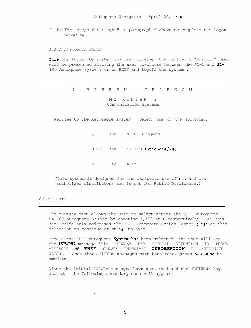
Autoquote Userguide - April 20, 1990
2) Perform steps 6 through 8 in paragraph 0 above to complete the logonprocedure.
3.3.2 AUTOQVOTE MENUS
Once the Autoqoute system has been accessed the following "primary" menuwill be presented allowing the user to-choose between the SL-1 and SL-100 Autoqoute systems or to EXIT and logoff the system.:
N 0 R T H E R N T E L E C O M
M E ' R I D I A N 1Communication Systems
Welcome to the Autoquote system. Select one of the following:
1 for SL-1 Autoquote
1 0 0 for SL-100 Autoquote/PMI
E to Exit
(This system is designed for the exclusive use of NT1 and itsauthorized distributors and is not for Public Disclosure.)
Selection:-
The primary menu allows the user to select either the SL-1 Autoquote,SL-100 Autoquote or Exit by entering 1,100 or E respectively. As thisuser guide only addresses the SL-1 Autoquote System, enter 3 "1" at thisselection to continue or an "E" to Exit.
Once a the SL-1 Autoquote System.has been selected, the user will seethe INFORMA message file. PLEASE PAY SPECIAL ATTENTION TO THESEMESSAGES AS THEY CONVEY IMPORTANT INPORMATION TO AUTOQUOTEUSERS. Once these INFORM messages have been read, press <RETURN> tocontinue.
After the initial INFORM messages have been read and the <RETURN> keypressed, the following secondary menu will appear:
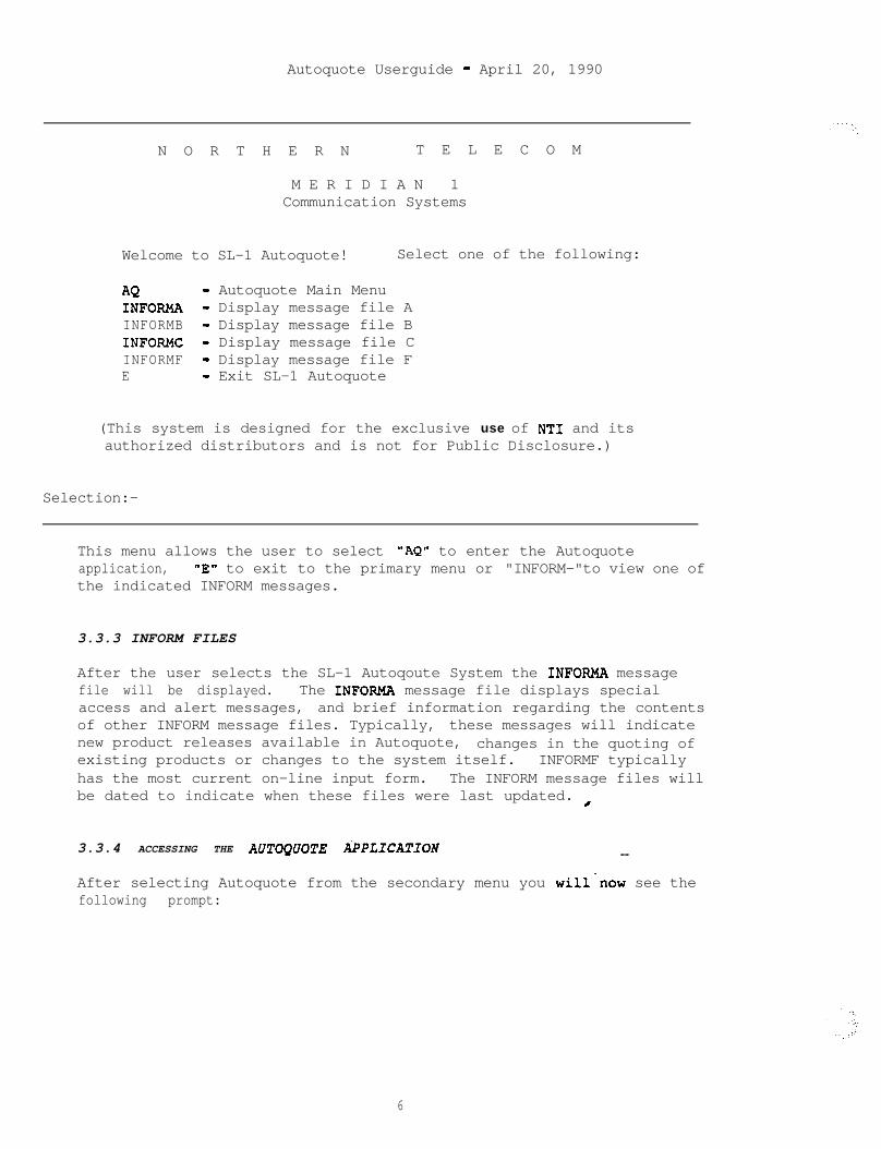
Autoquote Userguide - April 20, 1990
N O R T H E R N T E L E C O M
M E R I D I A N 1Communication Systems
Welcome to SL-1 Autoquote! Select one of the following:
AQ - Autoquote Main MenuINFORMA - Display message file AINFORMB - Display message file BINFOFWC - Display message file CINFORMF - Display message file FE - Exit SL-1 Autoquote
(This system is designed for the exclusive use of NT1 and itsauthorized distributors and is not for Public Disclosure.)
Selection:-
This menu allows the user to select "AQ" to enter the Autoquoteapplication, "E" to exit to the primary menu or "INFORM-"to view one ofthe indicated INFORM messages.
3.3.3 INFORM FILES
After the user selects the SL-1 Autoqoute System the INFORMA messagefile will be displayed. The INFORMA message file displays specialaccess and alert messages, and brief information regarding the contentsof other INFORM message files. Typically, these messages will indicatenew product releases available in Autoquote, changes in the quoting ofexisting products or changes to the system itself. INFORMF typicallyhas the most current on-line input form. The INFORM message files willbe dated to indicate when these files were last updated. /
3.3.4 ACCESSING THE AUTWUOTE APPLICATION --
After selecting Autoquote from the secondary menu you will*now see thefollowing prompt:
6
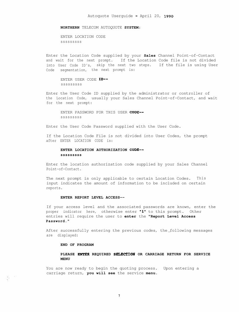
Autoquote Userguide - April 20, 1990
NORTHERN TELECOM AUTOQUOTE SYSTEM:
ENTER LOCATION CODEsssssssss
Enter the Location Code supplied by your Sales Channel Point-of-Contactand wait for the next prompt. If the Location Code file is not dividedinto User Code ID's, skip the next two steps. If the file is using UserCode segmentation, the next prompt is:
ENTER USER CODE ID--sssssssss
Enter the User Code ID supplied by the administrator or controller ofthe Location Code, usually your Sales Channel Point-of-Contact, and waitfor the next prompt:
ENTER PASSWORD FOR THIS USER CODE--sssssssss
Enter the User Code Password supplied with the User Code.
If the Location Code File is not divided into User Codes, the promptafter ENTER LOCATION CODE is:
ENTER LOCATION AUTHORIZATION CODE--sssssssss
Enter the location authorization code supplied by your Sales ChannelPoint-of-Contact.
The next prompt is only applicable to certain Location Codes. Thisinput indicates the amount of information to be included on certainreports.
ENTER REPORT LEVEL ACCESS--
If your access level and the associated passwords are known, enter theproper indicator here, otherwise enter "1" to this prompt. Otherentries will require the user to enter the "Report Level AccessPassword."
After successfully entering the previous codes, the following messages--are displayed:
END OF PROGRAM
PLEASE ENTER REQUIRED SnECTION OR CARRIAGE RETURN FOR SERVICEMENU
You are now ready to begin the quoting process. Upon entering acarriage return, you will see the service menu.
7
Autoguote Userguide - April 20, 1990
3.4 THE SERVICE MENU
All activities available in the Autoquote System begin at the ServiceMenu. The following message will appear when you are at the ServiceMenu:
PLEASE ENTER REQUIRED SELECTION OR CARRIAGE_RETURN FOR SERVICE
It is recommended that novice users always view the Service Menu whenfirst entering the Autoquote System. To view the menu, enter RETURN.
CODES: N- SET UP NEW QUOTE0- LOAD OLD QUOTEG- GENERAL INFORMATIONM- MODEL/SOFTWARE GENERICI- INPUTS- SAVE QUOTEX- AUX LOADR- REPORTL- LIST EXISTING QUOTESC- COPY OLD QUOTED- DELETE QUOTEQ- QUIT AUTOQUOTE
A quote must be loaded into your working file (option N or 0) before thefunctions G,M,I,S,X, and R can be used. The general procedure forsetting up a new quote requires using the options to:
1) Set up a new quote2) Save the quote .3) Run reports
These major options are explained in the following paragraphs alongwith the other available options shown in the service menu.
3.4.1 N - SET UP NEW QUOTE
Enter "NW to set up a new quote. The user is prompted for a set ofGeneral Information (G) and Model/Software Generic (M) entries. Uponcompletion of these entries, the user is automatically put into theinput phase without having to go back to the Service Menu. --
General Information/Model Code
All entries regarding General Information and Model Code are promptedwhen setting up a new quote. The prompts and appropriate responses arelisted below.
ENTERSALESMANNAME
Enter the name of+ the user and/or salesperson.
a
Autoquote Ueerguide - April 20, 1990
ENTER RUN TYPE: l=ACTUAL QUOTE, 2=CONFIRMATION QUOTE, 3=TEST QUOTE
Run types do not affect the result of an Autoquote but areused in the analysis of Autoguote usage. A valid entry isrequired.
ENTER CITY CODE FOR LABOR RATE
This input applies only to the Direct Sales channel. Entera carriage return for a listing of valid city codes, thenenter the appropriate code. A valid entry is required; theentry will be validated by Autoguote.
ENTER END-USER INDUSTRY CODE
Enter a carriage return for a listing of the industry codes,then enter the appropriate code. A valid entry isrequired; the entry will be validated by Autoquote.
ENTER END-USER COMPANY NAME
Enter the customer's company name.
ENTER END-USER LOCATION
Enter the company's business location.
ENTER SYSTEM CUTOVER DATE (MMDDYY)
The cutover date must be equal to or greater than thecurrent date. Format is month, day and year (MMDDYY). Avalid entry is required.
ENTER MODEL GENERIC CODE
ENTER REZEASE NUMBER
These prompts determine the product and system type to bequoted. Refer to Section 1 of the various product chaptersfor valid responses to this prompt.
3.4.1.1 Inputs Phase--
After responding to the previous prompts, the us,er is now ready to inputhis data for each input class. For example, the input classes forMeridian 1 SL-1 are:
Software OptionsPhones, Lines and TrunksMiscellaneous/MemoryBasic Information
9

Autoquote Ueerguide - April 20, 1990
The program will prompt for each class in the order listed above.(Refer to the Inputs section of the various product chapters forinformation on the input classes.) In each class, there will be aprompt phase (questions asked by Autoquote) followed by the statement:
END OF PROMPTS
BEGIN MANUAL INPUT
The user simply answers the prompted questions (if any), and thenmanually inputs any other requirements. Prompted entries may be changedduring the manual input phase. Refer to paragraph 3.4.5.1 InputFormats, page 12 for detailed information of inputting data.
After all input entries have been completed, the Service Menu ispresented. At this point, the user may change General Information, _Model and/or Inputs by entering G, M and/or I respectively. Refer tothe explanations of these Service Menu selections in paragraphs: 3.4.3,3.4.4, and 3.4.5.
IMPORTANT: .It is recommended the quote be saved after initial input orafter any changes have been made. Otherwise, the data could be lost ifa communication line were to go down or the user began another quotewithout saving the current one.
3.4.2 0 - LOAD OLD QUOTE
When the "0" is selected from the Service Menu, the system will respondwith the following:
PLEASE ENTER OLD QUOTE NUMBER
Enter the old quote number. The existing quote numbers may be displayedusing the "L" command as described in paragraph para-num:List .
DO YOU WANT A PRINT OF THE SAVED DATA?(Y/N)
Enter "Y" if you want to view the inputs for this quote as the quote isloading. The inputs are printed out in their "raw" format. Thisfeature allows the inputs to be viewed without running a quote (i.e.entering the Report function - paragraph 3.4.8).
PLEASE ENTER REQUIRED SELECTION OR CARRIAGE RETURN FOR.SERVICEMENU
Now that the quote has been loaded into the working file, the user canselect another option from the Service Menu such as R for reports or Gto change the General Information.
10

Autoquote Userguide - April 20, 1990
3.4.3 G - GENERAL INFORMATION
This function allows the user to make changes to the General Informationentered when the quote was first created. Upon entering "G" at theService Menu, the user will be prompted for the following:
ENTER SALESMAN NAMEENTER RUN TYPE: l=ACTUAL QUOTE, 2=CONFIRNAT?ONQUOTE, 3=TEST QUOTEENTER CITY CODE FOR LABOR RATE (Direct Sales channel only)ENTER END-USER INDUSTRY CODEENTER END-USER COMPANY NAMEENTER END-USER LOCATIONENTER SYSTEM CUTOVER DATE (NMDDYY)
An explanation of these prompts is given in Section 3.4.1,-N-New,page 8.
3.4.4 M - MODEL/SOFTWARE GENERIC
This function allows the user to change the Model/Software Generic of anexisting quote. For example, if quote number 10 is an Option 21, itcould be changed to a Option 51 without having to re-input therequirements. Please refer to Introduction section of the variousproduct chapters for the valid Model/Generic codes. Upon entering "M"at the Service Menu, the user will be prompted for the following:
ENTER MODEL GENERIC CODEENTER RELEASE NUMBER
An explanation of these prompts is given in Section 3.4.1, N-New, page8.
3.4.5 I - INPUT
The "I" is entered at the Service menu when the user wishes to changethe inputs which were specified when the quote was first set up with the"N" command. The following prompt will appear:
PLEASE ENTER DESIRED INPUT CLASS, END OR CARRIAGE RETURN FOR THEINPUTMENU
If a carriage return is entered, an input menu will-display. ForMeridian 1 SL-1, the following input menu will appear:
S- SOFTWARE OPTIONSG- SOFTWARE OPTION GROUPSP- PHONES, LINES AND TRUNKSM- MISCELLANEOUS/MEMORYB- BASIC INFORMATION
Enter the appropriate letter for the input class desired.
11
Autoquote Ueerguide - April 20, 1990
Once a user is in a specific input category and all changes arecomplete, “END” may be entered to get back to the Input Menu or “ABORT”to return to the Service Menu. Refer to the Inputs section of eachproduct chapter for specific inputs.
3.4.5.1 Input Formats
Input of data into the MBS Autoquote System may be required in one ofthree different input types. These different types are needed for someinputs that require more information than others. For example, acertain input may need to include just a quantity whereas another mightneed to include a quantity "nnnn" and a "type." The three input formatsare as follows:
Input Type Format1 I/A2 I/A,A3 I/A,A,A
where I = Input code NumberA = an integer value and/or a one decimal value
When entering data, the input code is separated from the input datavalues by a slash ("/'*) and data values are separated from each other bya comma ('l,"). Blank spaces or leading zeros when entering data are notrequired or recommended. Some example inputs are shown below:
Type 1:Type 2:Type 3:
In some cases, not all data values need to be entered as Autoquote willsupply default values. Information on input defaults is included in theInputs section of each of the various product chapters.
Input Echo
7/10312~5/40,60,623/40017/1000;1015/10,15,3.5
Whether supplied by the end user or defaulted, the program will echoeach line of input back to the terminal for verification. Thi-s not onlyallows the user to verify each input, but also to view any-defaultedvalue. The echoed values do not contain a decimal point and appear tobe increased by a magnitude of 10. For example, Entering "l/l" willappear as OOl/OOOOOOlO.
3 . 4 . 6 S - S A V E Q U O T E
When "S" is selected for a new quote, the system will respond byassigning a quote number and providing a statement confirming the quote
12
Autoquote Userguide - April 20, 1990
has been saved. The quote will be saved for only four (4) months fromthe creation date. If necessary, the quote may be copied to a new quotenumber to extend the life four more months. The creation date of aquote is either the date it was saved for the first time or the date itwas copied.
When "S" is selected for an existing quote, the system will respond byproviding a statement confirming the quote has been saved.
3.4.7 x - AUX LOAD
Auxiliary loads are used to combine the engineering of a single ormultiple RPE sites and/or other peripheral devices with the main site orsystem. When "X" is entered, the system prompts for the AUX quotenumbers one at a time. After each AUX quote number is entered, pressENTER and the system will prompt for another. After all AUX quotenumbers have been entered, the user enters "END".
Refer to the Aux Loading section for Meridian 1 SL-1 chapter for acomplete description of the AUX LOAD requirements regarding RPE.
3.4.8 R - REPORT
This selection is used to generate reports on the quote. After the "R"is entered, there will be a pause while the computer runs through thecalculations. This phase of Autoquote may last from as little as 30seconds to as much as 5 minutes, depending on the system size and theactivity on the computer. After completing the calculations, the systemwill print the "Header" report which includes general information andAutoquote disclaimers. Autoquote disclaimers. The system will t
PLEASE ENTER REPORT NUMBER(S)
Reports may be requested in any order and may be entered one at a timeor several separated by commas. Refer to the Reports Section of eachthe various product chapters for a list of report numbers and titles.
All reports except the header are optional and can be printed as desiredby the user.
Enter "End" at the prompt to return to the Service Menu.--
3.4.9 L - LIST EXISTING QUOTES
This option allows a "directory" list to be displayed, showing all ofthe quotes in the file. The quotes are listed by quote number indescending order. When "L" is entered, the system prompts:
PLEASE ENTER QUOTE NUMBER TO LIST PROM OR CARRIAGE RE2UR.N
13

Autoguote Userguide - April 20, 1990
Enter the quote number from which you want the list to begin. Carriagereturn will cause the list to begin from the latest quote.
PLEASE ENTER NUMBER OF QUOTES TO BE DISPLAYED AT ONE TIRE OR END
When the number is entered, the system will list the 'number of quotesspecified. The list will start with the quote number specified and endafter the correct amount has been displayed.
After viewing the quotes in the list, the user can continue with morelistings or enter "END" to return to the Service Menu.
3.4.10 c - COPY OLD QUOTE
With this entry, the system will prompt for the quote number to be _copied. When the quote number is entered, the system makes a copy ofthe saved information and assigns it a new quote number with a newcreation date.
This feature allows a quote to be modified and saved without disturbingthe original quote.
3.4.11 D - DELETE OLD QUOTE
A quote may be deleted from the file if it is no longer needed. Afterentering "D" at the Service Menu, the system will prompt for the quotenumber to be deleted. A second prompt will echo back the quote numberto be deleted for verification.
3.4.12 Q - QUIT AUTOQUOTE
Enter "Q" at the Service Menu to return to the secondary Autoqoute menu.
3.5 HELP
When this User Guide is read and followed, the user will experiencelittle or no difficulty in using the MBS Autoquote System. If, however,questions or problems do arise, read the following subsections forassistance information. These items are presented in the order problemsmay be encountered when using the Autoquote system. --
3.5.1 Host Access
If, when accessing Autoquote, you encounter problems before getting thehost prompt (:)
Telenet Users call Telenet Customer Service at 800-336-0437.Direct Users call the Information Center at 214-437-8711
14
Autoquote Ueerguide - April 20, 1990
3.5.2 COMPUTER RELATED QUESTIONS
For computer access or terminal time-out problems, call the InformationCenter at 214-437-8111.
3.5.3 ACCESS OR AUTHORIZATION CODE QUE-STIONS
Call your Sales Channel Point-of-Contact or passwordadministrator/controller. Autoquote Administration cannot give outpassword information.
3.5.4 AUTOQUOTE OPERATIONAL OR TECHNICAL QUESTIONS
There are three sources of information available to answer Autoquoteand/or technical questions.
1) Consult this User Guide for both access and configurationinformation.
2) Call your NT support person or group (District Sales Manager).
3) Contact Autoquote Administration at (214) 437-8529.
3.5.5 PRICING QUESTIONS
Many pricing questions can be answered by consulting your pricingmanual. However, if the pricing manual does not contain the answer,contact your NT Representative.
4. CAVEATS
This section contains information on the characteristics andfunctionality of the Autoquote system. It is important that thissection is understood to prevent any misuse of the Autoquote system.
4.1 GENERAL--
The Meridian Autoquote System is a sales tool to be used in preparingquotations for new systems as well as some peripheral devices. Althoughthe system contains precise engineering rules, it does not perform anexhaustive and complete.system configuration of every potentialconfiguration. The engineering rules are designed to accuratelyconfigure an average system. Therefore, the user should always reviewthe reports produced by the system to ensure a correct and reasonableconfiguration. These reviews are necessitated by Autoquote programfunctionality and not by limitations of the products supported in theAutoquote System. c
.
15

Autoquote Userguide - April 20, 1990
Although a concerted effort has been made to engineer each Meridiansystem configuration completely with the Autoquote System, there may besituations requiring further engineering or configuration adjustments.Because of this, the price quoted by the Autoquote System applies onlyto the items of equipment and software listed in the.Equipment BreakoutReport. This report contains a line entry for each item of equipment orsoftware that is quoted. No item is priced into the quote unless it isdetailed in this report. Pricing adjustments will be required if thereare any additions or deletions to this list.
4.2 OPERATIONAL - SALES CHANNELS
The Autoquote System is used by all Sales Channels. For each SalesChannel, it quotes only those items which Northern Telecom supplies tothat channel. Autoquote may treat some inputs differently depending onthe Sales Channel.
16
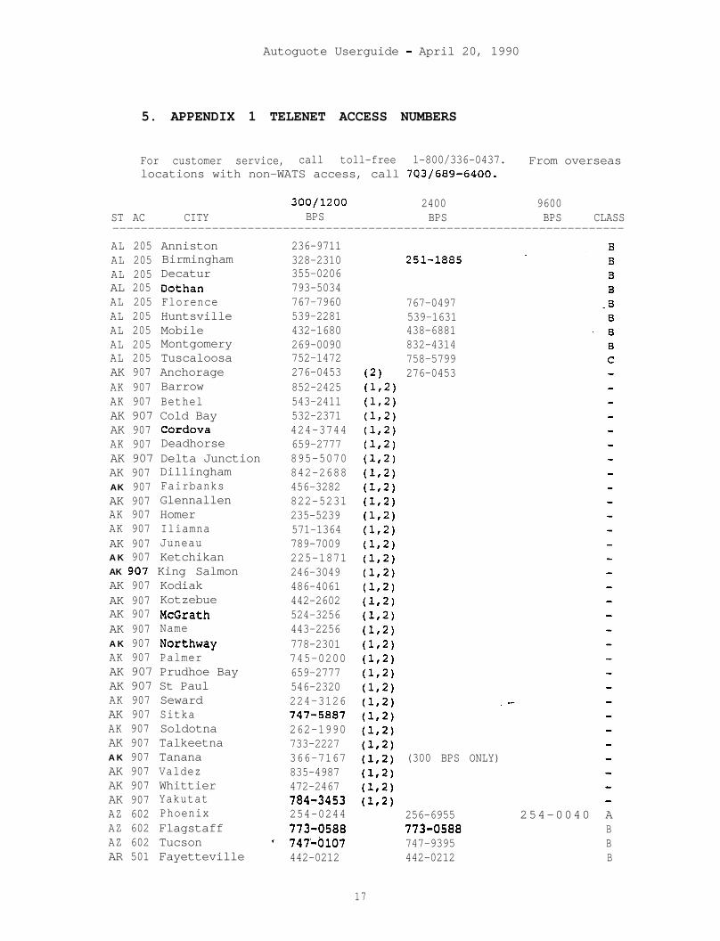
Autoguote Userguide - April 20, 1990
5. APPENDIX 1 TELENET ACCESS NUMBERS
For customer service, call toll-free l-800/336-0437. From overseaslocations with non-WATS access, call 7C3/689-6400.
300/1200 2400 9600ST AC CITY BPS BPS BPS CLASS------------------------------------------------------------------------AL 205 AnnistonAL 205 BirminghamAL 205 DecaturAL 205 DothanAL 205 FlorenceAL 205 HuntsvilleAL 205 MobileAL 205 MontgomeryAL 205 TuscaloosaAK 907 AnchorageAK 907 BarrowAK 907 BethelAK 907 Cold BayAK 907 CordovaAK 907 DeadhorseAK 907 Delta JunctionAK 907 DillinghamAK 907 FairbanksAK 907 GlennallenAK 907 HomerAK 907 IliamnaAK 907 JuneauA K 907 KetchikanAK 907 King SalmonAK 907 KodiakAK 907 KotzebueAK 907 McGrathAK 907 NameA K 907 NorthwayAK 907 PalmerAK 907 Prudhoe BayAK 907 St PaulAK 907 SewardAK 907 SitkaAK 907 SoldotnaAK 907 TalkeetnaA K 907 TananaAK 907 ValdezAK 907 WhittierAK 907 YakutatAZ 602 PhoenixAZ 602 FlagstaffAZ 602 TucsonAR 501 Fayetteville
236-9711328-2310355-0206793-5034767-7960539-2281432-1680269-0090752-1472276-0453852-2425543-2411532-2371424-3744659-2777895-5070842-2688456-3282822-5231235-5239571-1364789-7009225-1871246-3049486-4061442-2602524-3256443-2256778-2301745-0200659-2777546-2320224-3126747-5887262-1990733-2227366-7167835-4987472-2467784-3453254-0244773-0588
* 747-0107442-0212
251-1885
767-0497539-1631438-6881832-4314758-5799276-0453
. --
(300 BPS ONLY)
256-6955 254-0040 A773-0588 B747-9395 B442-0212 B
17
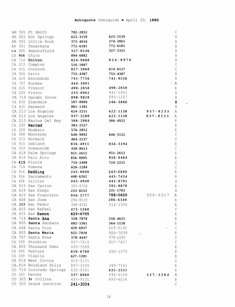
Autoquote Userguide - April 20, 1990
AR 501 Ft SmithAR 501 Hot SpringsAR 501 Little RockAR 501 TexarkanaCA 805 BakersfieldCA 916 ChicoCA 714 ColtonCA 213 ComptonCA 415 ConcordCA 916 DavisCA 619 EscondidoCA 707 EurekaCA 415 FremontCA 209 FresnoCA 714 Garden GroveCA 818 GlendaleCA 415 HaywardCA 213 Los AngelesCA 213 Los AngelesCA 213 Marina Del ReyCA 209 MercedCA 209 ModestoCA 408 MontereyCA 213 NorwalkCA 415 OaklandCA 619 OceansideCA 619 Palm SpringsCA 415 Palo AltoCA 415 PinoleCA 714 PomonaCA 916 ReddingCA 916 SacramentoCA 408 SalinasCA 415 San CarlosCA 619 San DiegoCA 415 San FranciscoCA 408 San JoseCA 213 San PedroCA 415 San RafaelCA 415 San RamonCA 714 Santa AnaCA 805 Santa BarbaraCA 408 Santa CruzCA 805 Santa MariaCA 707 Santa RosaCA 209 StocktonCA 805 Thousand OaksCA 805 VenturaCA 209 VisaliaCA 818 West CovinaCA.818 Woodland HillsCO 719 Colorado SpringsCO 303 DenverCO 303 Ft CollinsCO 303 Grand Junction
782-2852623-3159372-4616772-6181327-8146894-6882824-9000516-1007827-3960753-4387741-7756444-3091490-2050233-0961898-9820507-0909881-1382624-2251937-3580306-2984383-2557576-2852646-9092404-2237836-4911430-0613951-2612856-9995724-2400626-1284243-0690448-6262443-4940591-0726233-0233956-5777294-9119548-6141472-5360829-6705558-7078682-5361429-6937925-7039578-4447957-7610495-3588656-6760627-1201915-5151887-3160635-5361337-6060493-9131.241-3004
623-3159374-2861772-6181327-5321
8 2 4 - 8 9 7 6 -
674-0127753-4387741-9536
490-2050441-1861895-1207246-3886
622-1138622-1138306-4922
646-5122
834-3194
951-2612856-0484724-2225
243-0690443-7434443-8791595-8870231-1703788-0825286-6340514-1590
550-4625564-1158429-9192925-7039 .578-1055957-7627
650-1070
348-7141635-2551696-0159493-4014
CBBBBBBCCBB
_ BBBBB _B
9 3 7 - 0 2 3 3 A9 3 7 - 0 2 3 3 A
BBBCCBCBBCCBBBBB
956-6317 ABBCBBB
-- CBCCBBBCBB
3 3 7 - 3 3 0 4 ABC
18

Autoquote Userguide - April 20, 1990
CO 303 Greeley 3 5 2 - 8 5 6 3CO 719 Pueblo 5 4 2 - 4 0 5 3CT 203 Bridgeport 3 3 5 - 5 0 5 5CT 203 Danbury 7 9 4 - 9 0 7 5CT 203 Hartford 2 4 7 - 9 4 7 9CT 203 Middletown. 3 4 4 - 8 2 1 7CT 203 New Britain 2 2 5 - 7 0 2 7CT 203 New Haven 6 2 4 - 5 9 5 4CT 203 New London 4 4 7 - 8 4 5 5CT 203 Norwalk 8 6 6 - 7 4 0 4CT 203 Stamford 3 4 8 - 0 7 8 7CT 203 Waterbury 7 5 3 - 4 5 1 2DE 302 Dover 6 7 8 - 8 3 2 8DE 302 Newark 4 5 4 - 7 7 1 0DC 202 Washington 4 2 9 - 7 8 9 6DC 202 Washington 4 2 9 - 7 8 0 0FL 407 Boca Raton 3 3 8 - 3 7 0 1FL 813 Cape Coral 2 7 5 - 7 9 2 4FL 407 Cocoa Beach 2 6 7 - 0 8 0 0FL 904 Daytona Beach 2 5 5 - 2 6 2 9FL 305 Ft Lauderdale 7 6 4 - 4 5 0 5FL 813 Ft Myers 2 7 5 - 4 1 5 3FL 407 Ft Pierce 4 6 6 - 4 5 6 6FL 904 Gainesville 3 3 8 - 0 2 2 0FL 904 Holly Hill 2 5 7 - 4 7 7 0FL 904 Jacksonville 3 5 3 - 1 8 1 8FL 813 Lakeland 6 8 3 - 5 4 6 1FL 904 Leesburg 7 8 7 - 0 7 9 9FL 407 Melbourne 2 4 2 - 8 2 4 7FL 305 Miami 3 7 2 - 0 2 3 0
. FL 813 Naples 2 6 3 - 3 0 3 3FL 904 Ocala 3 5 1 - 3 7 9 0FL 407 Orlando 4 2 2 - 4 0 8 8FL 904 Panama City 7 6 3 - 8 3 7 7FL 904 Pensacola 4 3 2 - 1 3 3 5FL 305 Pompano Beach 9 4 1 - 5 4 4 5FL 813 St Petersburg 3 2 3 - 4 0 2 6FL 813 Sarasota 9 2 3 - 4 5 6 3FL 904 Tallahassee 681-1902FL 813 Tampa 224-9920FL 904 Valparaiso 897-3421FL 407 West Palm Beach 833-6691GA 912 Albany 888-3011GA 404 Athens 548-5590GA 404 Atlanta 5 2 3 - 0 8 3 4GA 404 Augusta 7 2 4 - 2 7 5 2GA 404 Columbus 5 7 1 - 0 5 5 6GA 404 Gainsville 532-9880GA 912 Macon 743-8844GA 4 0 4 Rome 2 3 4 - 1 4 2 8GA 912 Savannah 2 3 6 - 2 6 0 5HI 808 Oahu 528-0200HI 800 Other Islands 272-5299ID 208 Boise .d 343;0611ID 208 Idaho Falls 5 2 9 - 0 4 0 6
19
367-9130792-5354724-9396
7-73-3569437-0909
359-94047 5 6 - 0 3 4 2
7 3 7 - 4 3 4 04 2 9 - 0 9 5 64 2 9 - 0 9 5 6
5 2 4 - 5 3 0 42 7 5 - 4 1 5 34 6 6 - 4 5 6 63 3 8 - 1 7 0 02 5 7 - 4 7 7 0791-92016 8 7 - 0 6 6 67 8 7 - 0 7 9 9
3 7 2 - 1 3 5 5
351-02634 2 2 - 8 8 5 87 6 3 - 8 3 7 74 3 4 - 2 1 0 3
3 2 7 - 1 1 6 39 2 5 - 1 4 9 9561-8830223-5859897-3421655-2993431-9384
--584-0212 _724-4494323-8931532-9880741-2108
2 3 6 - 2 8 7 55 2 8 - 0 2 0 0 ( 2 )2 7 2 - 5 2 9 9 ( 2 )3 4 3 - 1 2 7 25 2 9 - 0 4 0 6
BCBBBBBBBBBCBB
429-9145 A429-9145 . A
CCBCBBBBBBCBC
372-9684 ACCBBCCBCBBBBCB
523-5512 ABBBCBB
BB

Autoquote Userguide - April 20, 1990
IL 312 AuroraIL 618 BelleviewIL 309 BloomingtonIL 312 ChicagoIL 217 DecaturIL 815 DekalbIL 815 JolietIL 708 LibertyvilleIL 708 NapervilleIL 309 PeoriaIL 815 RockfordIL 217 Springfield -IL 217 UrbanaIN 812 BloomingtonIN 812 EvansvilleIN 219 Ft WayneIN 219 GaryIN 317 IndianapolisIN 317 KokomoIN 317 LafayetteIN 317 MuncieIN 219 South BendIN 812 Terre HauteIA 515 AmesIA 319 BurlingtonIA 319 Cedar RapidsIA 319 DavenportIA 515 Des MoinesIA 319 DubuqueIA 319 Iowa CityIA 712 Sioux CityIA 319 WaterlooKS 913 LawrenceKS 913 LeavenworthKS 913 ManhattanKS 913 SalinaKS 913 TopekaKS 316 WichitaKY 502 Bowling GreenKY 502 FrankfortKY 606 LexingtonKY 502 LouisvilleKY 502 CwensboroLA 318 AlexandriaLA 504 Baton RougeLA 318 LafayetteLA 318 Lake CharlesLA'318 MonroeLA 504 New OrleansLA 318 ShreveportME 207 AugustaME 207 Brewer
ID 208 Lewiston 743-0099ID 208 Pocatella 232-1764IL 312 Arlington Heights 255-6465
896-0620227-5483827-7000938-0600429-0235758-2623726-0070362-7838355-2910637-8570965-0400753-1373384-6428332-1344424-7693426-2268882-8800299-0024455-2460742-6000282-6418233-7104232-5329233-6300752-2516364-0911324-2445288-4403556-0783351-1421255-1545232-5441843-8124651-0015537-0948825-7900233-9880262-5669782-7941875-4654233-0312589-5580686-8107445-1053343-0753233-0002436-0518387-6330524-4094221-5833,.622-3123989-3081
743-5885232-1764255-6465896-3363227-5483828-2573938-8725429-6054758-5046726-8731362-7838355-2910637-8582965-0696753-1391328-0317
428-2522422-3431882-1835299-6766452-0073
233-4031234-4119233-2603752-2516362-2764324-8902288-6206
354-0676
232-0195
651-0015
233-4660262-7961782-6380875-1942233-7217583-1006
343-0771234-8451
322-9826522-3967424-2255622-7364
CBABBB
938-4401 ACBCB
_ BBB.BB _CBBBBCCCBCCBBCBCCCBBBBBBBBB_-BBBBABCB
524-7337 ABBC
20
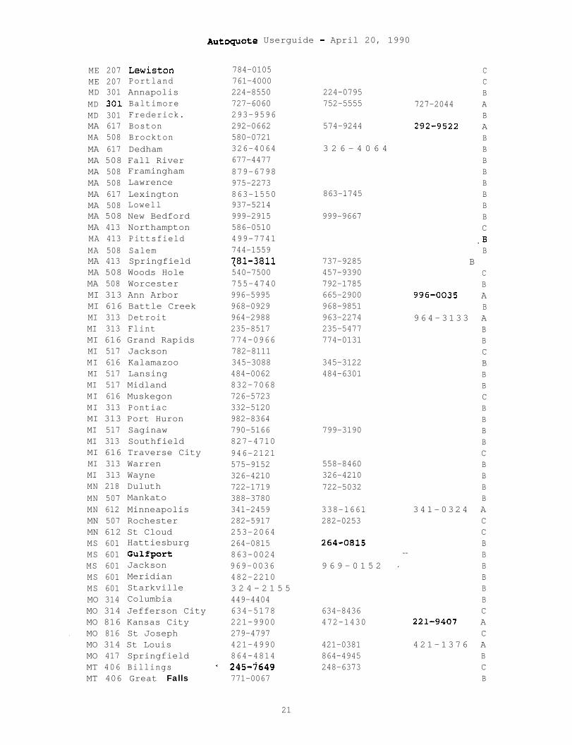
ME 207 Lewiston 784-0105ME 207 Portland 761-4000MD 301 Annapolis 224-8550 224-0795MD 301 Baltimore 727-6060 752-5555MD 301 Frederick. 293-9596MA 617 Boston 292-0662 574-9244MA 508 Brockton 580-0721MA 617 Dedham 326-4064 3 2 6 - 4 0 6 4MA 508 Fall River 677-4477MA 508 Framingham 879-6798MA 508 Lawrence 975-2273MA 617 Lexington 863-1550 863-1745MA 508 Lowell 937-5214MA 508 New Bedford 999-2915 999-9667MA 413 Northampton 586-0510MA 413 Pittsfield 499-7741MA 508 Salem 744-1559MA 413 Springfield 781-3811 737-9285MA 508 Woods Hole 540-7500 457-9390MA 508 Worcester 755-4740 792-1785MI 313 Ann Arbor 996-5995 665-2900MI 616 Battle Creek 968-0929 968-9851MI 313 Detroit 964-2988 963-2274MI 313 Flint 235-8517 235-5477MI 616 Grand Rapids 774-0966 774-0131MI 517 Jackson 782-8111MI 616 Kalamazoo 345-3088 345-3122MI 517 Lansing 484-0062 484-6301MI 517 Midland 832-7068MI 616 Muskegon 726-5723MI 313 Pontiac 332-5120MI 313 Port Huron 982-8364MI 517 Saginaw 790-5166 799-3190MI 313 Southfield 827-4710MI 616 Traverse City 946-2121MI 313 Warren 575-9152 558-8460MI 313 Wayne 326-4210 326-4210MN 218 Duluth 722-1719 722-5032MN 507 Mankato 388-3780MN 612 Minneapolis 341-2459 338-1661MN 507 Rochester 282-5917 282-0253MN 612 St Cloud 253-2064MS 601 Hattiesburg 264-0815 264-0815MS 601 Gulfport 863-0024 --MS 601 Jackson 969-0036 9 6 9 - 0 1 5 2 _MS 601 Meridian 482-2210MS 601 Starkville 3 2 4 - 2 1 5 5MO 314 Columbia 449-4404MO 314 Jefferson City 634-5178 634-8436MO 816 Kansas City 221-9900 472-1430
. MO 816 St Joseph 279-4797MO 314 St Louis 421-4990 421-0381MO 417 Springfield 864-4814 864-4945MT 406 Billings - 245-7649 248-6373MT 406 Great Falls 771-0067
Autoquote Userguide - April 20, 1990
CCB
727-2044 AB
292-9522 ABBBBBBBBC
.BB
BCB
996-0035 AB
964-3133 ABBCBBBCBBBBCBBBB
341-0324 ACCBBBBBBC
221-9407 AC
421-1376 ABCB
21
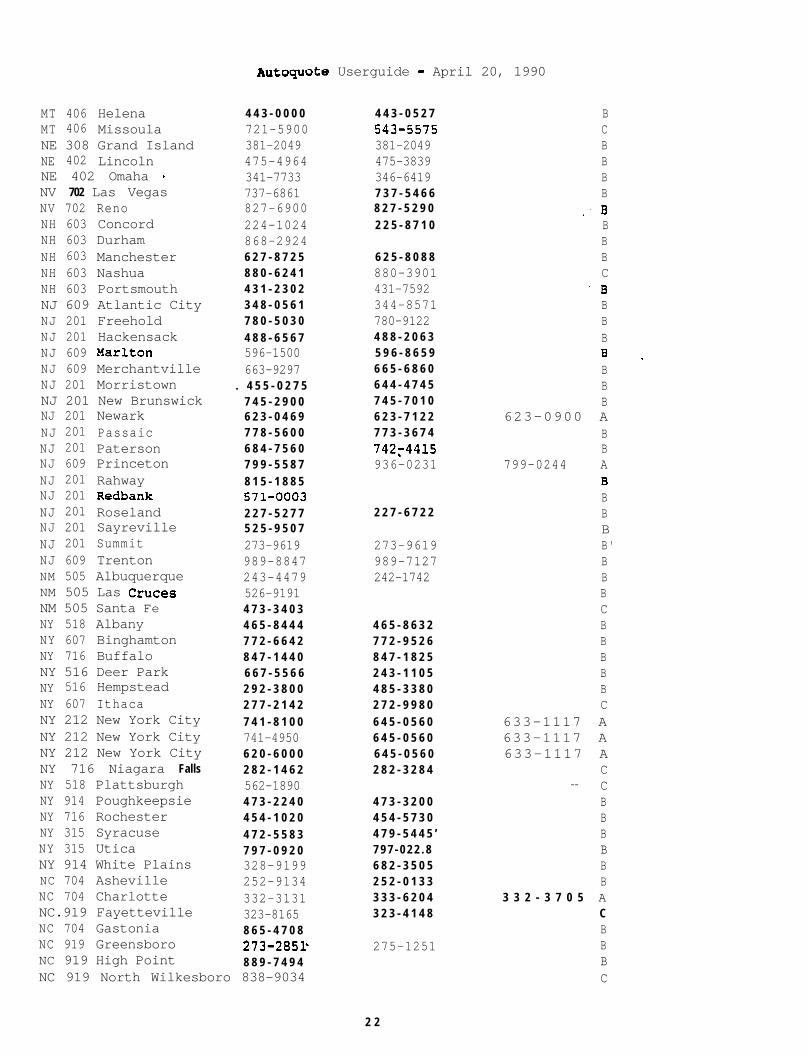
MT 406 HelenaMT 406 MissoulaNE 308 Grand IslandNE 402 LincolnNE 402 Omaha *NV 702 Las VegasNV 702 RenoNH 603 ConcordNH 603 DurhamNH 603 ManchesterNH 603 NashuaNH 603 PortsmouthNJ 609 Atlantic CityNJ 201 FreeholdNJ 201 HackensackNJ 609 MarltonNJ 609 MerchantvilleNJ 201 MorristownNJ 201 New BrunswickNJ 201 NewarkNJ 201 PassaicNJ 201 PatersonNJ 609 PrincetonNJ 201 RahwayNJ 201 RedbankNJ 201 RoselandNJ 201 SayrevilleNJ 201 SummitNJ 609 TrentonNM 505 AlbuquerqueNM 505 Las CrucesNM 505 Santa FeNY 518 AlbanyNY 607 BinghamtonNY 716 BuffaloNY 516 Deer ParkNY 516 HempsteadNY 607 IthacaNY 212 New York CityNY 212 New York CityNY 212 New York CityNY 716 Niagara FallsNY 518 PlattsburghNY 914 PoughkeepsieNY 716 RochesterNY 315 SyracuseNY 315 UticaNY 914 White PlainsNC 704 AshevilleNC 704 CharlotteNC.919 FayettevilleNC 704 GastoniaNC 919 GreensboroNC 919 High Point
--------&"I Userguide - April 20, 1990A”SPqIA”L=
4 4 3 - 0 0 0 0721-5900381-2049475-4964341-7733737-6861827-6900224-1024868-29246 2 7 - 8 7 2 58 8 0 - 6 2 4 14 3 1 - 2 3 0 23 4 8 - 0 5 6 17 8 0 - 5 0 3 04 8 8 - 6 5 6 7596-1500663-9297
. 4 5 5 - 0 2 7 57 4 5 - 2 9 0 06 2 3 - 0 4 6 97 7 8 - 5 6 0 06 8 4 - 7 5 6 07 9 9 - 5 5 8 78 1 5 - 1 8 8 5571-00032 2 7 - 5 2 7 75 2 5 - 9 5 0 7273-9619989-8847243-4479526-91914 7 3 - 3 4 0 34 6 5 - 8 4 4 47 7 2 - 6 6 4 28 4 7 - 1 4 4 06 6 7 - 5 5 6 62 9 2 - 3 8 0 02 7 7 - 2 1 4 27 4 1 - 8 1 0 0741-49506 2 0 - 6 0 0 02 8 2 - 1 4 6 2562-18904 7 3 - 2 2 4 04 5 4 - 1 0 2 04 7 2 - 5 5 8 37 9 7 - 0 9 2 0328-9199252-9134332-3131323-81658 6 5 - 4 7 0 8273-2851-8 8 9 - 7 4 9 4
NC 919 North Wilkesboro 838-9034
4 4 3 - 0 5 2 7543-557s381-2049475-3839346-64197 3 7 - 5 4 6 68 2 7 - 5 2 9 02 2 5 - 8 7 1 0
6 2 5 - 8 0 8 8880-3901431-7592344-8571780-91224 8 8 - 2 0 6 35 9 6 - 8 6 5 96 6 5 - 6 8 6 06 4 4 - 4 7 4 57 4 5 - 7 0 1 06 2 3 - 7 1 2 27 7 3 - 3 6 7 474274415936-0231
2 2 7 - 6 7 2 2
273-9619989-7127242-1742
4 6 5 - 8 6 3 27 7 2 - 9 5 2 68 4 7 - 1 8 2 52 4 3 - 1 1 0 54 8 5 - 3 3 8 02 7 2 - 9 9 8 06 4 5 - 0 5 6 06 4 5 - 0 5 6 06 4 5 - 0 5 6 02 8 2 - 3 2 8 4
4 7 3 - 3 2 0 04 5 4 - 5 7 3 04 7 9 - 5 4 4 5 ’7 9 7 - 0 2 2 . 86 8 2 - 3 5 0 52 5 2 - 0 1 3 33 3 3 - 6 2 0 43 2 3 - 4 1 4 8
275-1251
BCBBBB
.BBBBC
-BBBBB _BBB
623-0900 ABB
799-0244 AB.BBBB'BBBCBBBBBC
633-1117 A633-1117 A633-1117 A
C-- C
BBBBBB
3 3 2 - 3 7 0 5 ACBBBC
2 2
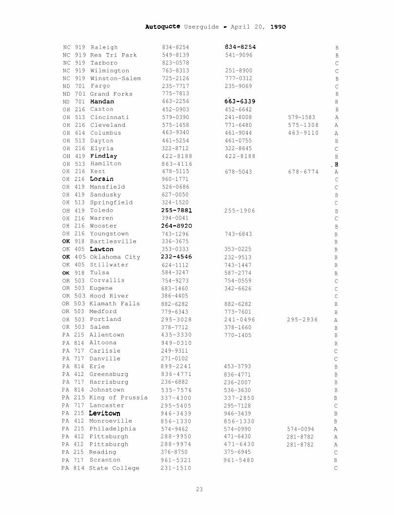
Autoguote Userguide - April 20, 1990
NC 919 Raleigh 834-8254NC 919 Res Tri Park 549-8139NC 919 Tarboro 823-0578NC 919 Wilmington 763-8313NC 919 Winston-Salem 725-2126ND 701 Fargo 235-7717ND 701 Grand Forks 775-7813ND 701 Mandan 663-2256OH 216 Canton 452-0903OH 513 Cincinnati 579-0390OH 216 Cleveland 575-1658OH 614 Columbus 463-9340OH 513 Dayton 461-5254OH 216 Elyria 322-8712OH 419 Findlay 422-8188OH 513 Hamilton 863-4116OH 216 Kent 678-5115OH 216 Lorain 960-1771OH 419 Mansfield 526-0686OH 419 Sandusky 627-0050OH 513 Springfield 324-1520OH 419 Toledo 255-7881OH 216 Warren 394-0041OH 216 Wooster 264-8920OH 216 Youngstown 743-1296OK 918 Bartlesville 336-3675OK 405 Lawton 353-0333OK 405 Oklahoma City .232-4546OK 405 Stillwater 624-1112OK 918 Tulsa 584-3247OR 503 Corvallis 754-9273OR 503 Eugene 683-1460OR 503 Hood River 386-4405OR 503 Klamath Falls 882-6282OR 503 Medford 779-6343OR 503 Portland 295-3028OR 503 Salem 378-7712PA 215 Allentown 435-3330PA 814 Altoona 949-0310PA 717 Carlisle 249-9311PA 717 Danville 271-0102PA 814 Erie 899-2241PA 412 Greensburg 836-4771PA 717 Harrisburg 236-6882PA 814 Johnstown 535-7576PA 215 King of Prussia 337-4300PA 717 Lancaster 295-5405PA 215 Levitown 946-3439PA 412 Monroeville 856-1330PA 215 Philadelphia 574-9462PA 412 Pittsburgh 288-9950PA 412 Pittsburgh 288-9974PA 215 Reading 376-8750PA 717 Scranton 961-5321PA 814 State College 231-1510
23
834-8254541-9096
251-8900777-0312235-9069
6k3-6339452-6642241-8008771-6480461-9044461-0755322-8645422-8188
579-1583575-1308463-9110
678-5043 678-6774
255-1906
743-6843
353-0225232-9513743-1447587-2774754-0559342-6626
882-6282773-7601241-0496378-1660770-1405
295-2936
453-3793836-4771236-2007536-3630337-2850295-7128946-3439856-1330574-0990471-6430471-6430375-6945961-5480
574-0094281-8782281-8782
BBCCBCBBBAAABCB
-BACCBCBCBBBBBBBCCCBBABBBCCBBBBBCBBAAACBC

Autoquote Userguide - April 20, 1990
PA 215 Warrington 343-6010PA 215 West Chester 4 3 6 - 7 4 0 6PA 717 Wilkes-Barre 829-3108PA 717 Williamsport 494-1796PA 717 York 8 4 6 - 6 5 5 0RI 401 Providence 751-7912RI 401 North Kingston 295-7100RI 401 Woonsocket 4 6 6 - 4 5 6 6SC 803 Charleston 7 2 2 - 4 3 0 3SC 803 Columbia 2 5 4 - 0 6 9 5SC 803 Greenville 2 3 3 - 3 4 8 6SC 803 Spartanburg 5 8 5 - 1 6 3 7SD 605 Pierre 2 2 4 - 0 4 8 1SD 605 Rapid City 3 4 8 - 2 6 2 1SD 605 Sioux Falls 3 3 6 - 8 5 9 3TN 615 Bristol 968-1130TN 615 Chattanooga 756-1161TN 615 Clarksville 5 5 2 - 0 0 3 2TN 615 Johnson City 2 8 2 - 6 6 4 5TN 615 Knoxville 5 2 3 - 5 5 0 0TN 901 Memphis 5 2 1 - 0 2 1 5TN 615 Nashville 2 4 4 - 3 7 0 2TN 615 Oak Ridge 481-3590TX 915 Abilene 676-9151TX 806 Amarillo 3 7 3 - 0 4 5 8TX 214 Athens 6 7 7 - 1 7 1 2TX 512 Austin 928-1130TX 512 Brownsville 5 4 2 - 0 3 6 7TX 409 Bryan 822-0159TX 512 Corpus Christi 884-9030TX 214 Dallas 748-6371TX 817 Denton 381-1897TX 915 El Paso 532-7907TX 817 Ft Worth 3 3 2 - 4 3 0 7TX 409 Galveston 7 6 2 - 4 3 8 2TX 713 Houston 2 2 7 - 1 0 1 8TX 512 Laredo 724-1791TX 214 Longview 2 3 6 - 4 2 0 5TX 806 Lubbock 7 4 7 - 4 1 2 1TX 512 McAllen 6 8 6 - 5 3 6 0TX 915 Midland 561-9811TX 409 Nederland 7 2 2 - 3 7 2 0TX 915 San Angelo 9 4 4 - 7 6 2 1TX 512 San Antonio 2 2 S - 8 0 0 4TX 214 Sherman 8 9 3 - 4 9 9 5TX 817 Temple 7 7 3 - 9 7 2 3TX 214 Tyler 5 9 7 - 8 9 2 5TX 512 Victoria 5 7 2 - 3 1 9 7TX 817 Waco 7 5 2 - 9 7 4 3TX 817 Wichita Falls 3 2 2 - 3 7 7 4UT.801 Logan 7 5 2 - 3 4 2 1UT 801 Ogden 6 2 7 - 1 6 3 0UT 801 Provo 373-0542UT 801 Salt Lake City 3 5 9 - 0 1 4 9VT 802 Burlington 8 6 4 - 0 8 0 8
343-60104 3 6 - 7 4 0 68 2 4 - 8 2 0 9
BBBCBBBBBBB
_ BBCBc _BBCBBBCBBCBCCB
748-3541 ACB
3 3 2 - 8 4 2 4 AB
227-1760 ACCCBBBB- -
,. BBCCBCBBCBBB
843-0039831-3990295-7100 -4 6 6 - 4 5 6 65 7 7 - 4 7 1 02 5 2 - 0 3 2 82 7 1 - 0 2 3 1
2 2 4 - 2 2 5 7
3 3 6 - 6 4 3 89 6 8 - 2 4 8 02 6 5 - 7 9 2 9
5 2 1 - 5 0 7 25 2 7 - 5 1 7 52 5 5 - 2 6 0 8
373-1833
929-36225 4 4 - 7 0 7 3
884-6946745-1359381-1897541-1931332-6794765-72982 2 7 - 8 2 0 8
6 8 6 - 2 4 5 2561-8597727-4090949-12312 2 5 - 3 4 4 4
572-3197
7 5 2 - 3 4 2 16 2 7 - 1 6 4 03 7 5 - 2 0 8 43 5 9 - 0 5 7 8
2 4
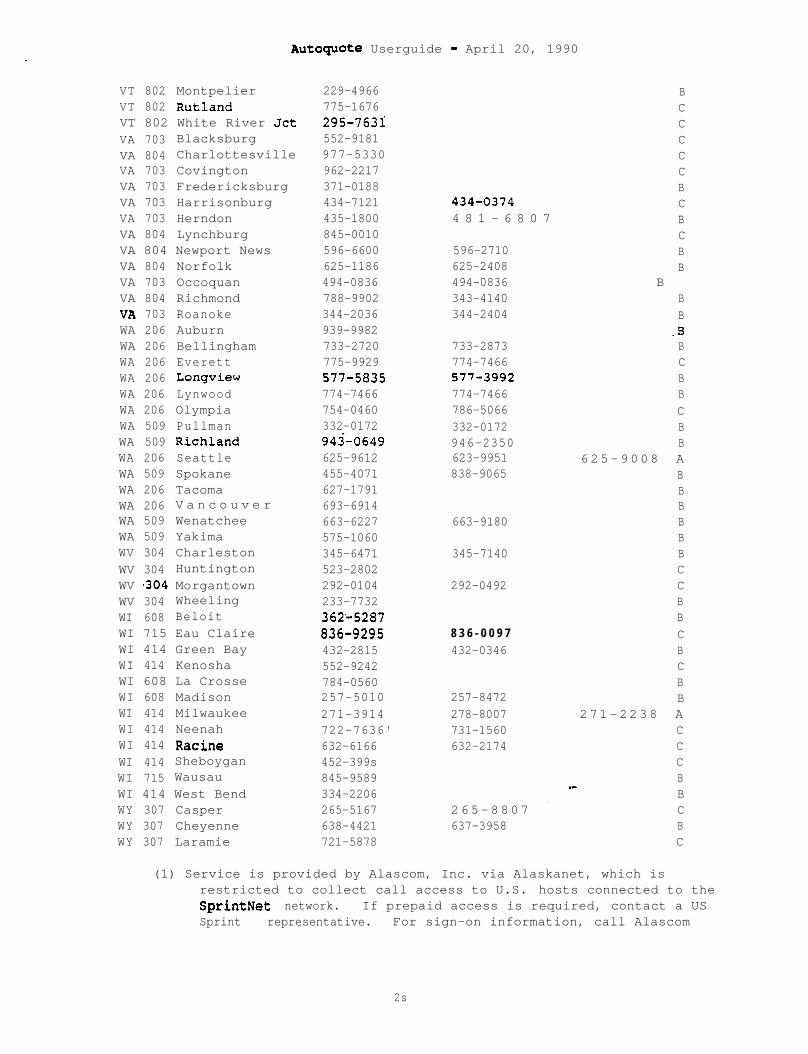
Autoguote Userguide - April 20, 1990
VT 802 Montpelier 229-4966VT 802 Rutland 775-1676VT 802 White River Jet 295-7631:VA 703 Blacksburg 552-9181VA 804 Charlottesville 977-5330VA 703 Covington 962-2217VA 703 Fredericksburg 371-0188VA 703 Harrisonburg 434-7121VA 703 Herndon 435-1800VA 804 Lynchburg 845-0010VA 804 Newport News 596-6600VA 804 Norfolk 625-1186VA 703 Occoquan 494-0836VA 804 Richmond 788-9902VA 703 Roanoke 344-2036WA 206 Auburn 939-9982WA 206 Bellingham 733-2720WA 206 Everett 775-9929WA 206 Longview 577-5835WA 206 Lynwood 774-7466WA 206 Olympia 754-0460WA 509 Pullman 332-0172WA 509 Richland 943'-0649WA 206 Seattle 625-9612WA 509 Spokane 455-4071WA 206 Tacoma 627-1791WA 206 V a n c o u v e r 693-6914WA 509 Wenatchee 663-6227WA 509 Yakima 575-1060WV 304 Charleston 345-6471WV 304 Huntington 523-2802WV ~304 Morgantown 292-0104WV 304 Wheeling 233-7732WI 608 Beloit 362.-5287WI 715 Eau Claire 836-9295WI 414 Green Bay 432-2815WI 414 Kenosha 552-9242WI 608 La Crosse 784-0560WI 608 Madison 257-5010WI 414 Milwaukee 271-3914WI 414 Neenah 722-7636'WI 414 Racine 632-6166WI 414 Sheboygan 452-399sWI 715 Wausau 845-9589WI 414 West Bend 334-2206WY 307 Casper 265-5167WY 307 Cheyenne 638-4421WY 307 Laramie 721-5878
434-03744 8 1 - 6 8 0 7
596-2710625-2408494-0836343-4140344-2404
733-2873774-7466577-3992774-7466786-5066332-0172946-2350623-9951838-9065
663-9180
345-7140
292-0492
8 3 6 - 0 0 9 7432-0346
257-8472278-8007731-1560632-2174
265-8807 _637-3958
BCCCCCBCBCBB
BBB
.BBCBBCBB
625-9008 ABBBBBBCCBBCBCBB
271-2238 ACCCB_-BCBC
(1) Service is provided by Alascom, Inc. via Alaskanet, which isrestricted to collect call access to U.S. hosts connected to theSprintNet network. If prepaid access is required, contact a USSprint representative. For sign-on information, call Alascom
2s

Autoquote Userguide - April 20, 1990
Customer Service at 907/264-7391 (inside Alaska) or l-8001544-2233(outside Alaska).
(2) International data rate schedule applies.
* An asterisk indicates a change in number, a service upgrade or a newlocation. Refer to the 'New' listing for further explanations ofthese changes.
26
.’
Meridian I
AUTOQUOTE USER GUIDE
MERIDIAN 1 SL-1
Et northorntelcrcom

--
Autoquote Userguide - April 20, 1990
MERIDIAN 1 SL-1PRIVATE BRANCH EXCHANGE COMMUNICATION SYSTEM
AUTOQUOTE USER GUIDE CHAPTER
1. INTRODUCTION . . . . . . . . . . . . . . . . . . . . . . . . . . . . . . . . . . . . . . . . . . . . 1
1.1 PRODUCT DESCRIPTION...............................1
1.2 VALID MODELS.. . . . . . . . . . . . . . . . . . . . . . . . . . . . . . . . . . . . . 1
2. INPUTS . . . . . . . . . . . . . . . . . . . . . . . . . . . . . . . . . . . . . . . . . . . . . . . . . . 3
2.1 INPUT CLASSES.... . . . . . . . . . . . . . . . . . . . . . . . . . . . . . . . . . 3
2.2 INPUT CODES, DESCRIPTIONS, AND DEFAULT VALUES- .. ...42.2.1 Software Option Input8 ............................... 42.2.2 Phones, Lines, and Trunks ............................ a
2.2.2.1 Port Inputs .................................. 82.2.2.1.1 Traffic Defaults Table ................... ..Y
2.2.3 Miscellaneous/Memory ................................ 152.2.4 Basic Information ................................... 25
3. ENGINEERING/PROVISIONING . . . . . . . . . . . . . . . . . . . . . . . . . . . . . . . 27
3.1 SOFTWARE PROVISIONING . . . . . . . . . . . . . . . . . . . . . . . . . . . . 28
3.2 PERIPHERAL EQUIPMENT CARDS AND MODULES;..........3 03.2.1 IPE Cards ........................................... 303.2.2 EPE Cards ........................................... 313.2.3 Digitone Receivers .................................. 31
3.2.3.1 DTR Traffic ................................. 323.2.3.2 DTR Port Provisioning Table.................3 33.2.3.3 DTR Cards ................................... 34
3.2.4 Tone Detector ....................................... 343.2.5 IPE Modules ......................................... 343.2.6 EPE Modules ......................................... 34
3.2.6.1 Controller Cards ............................. 343.2.6.2 Ringing Generators .......................... 34
3.3 NETWORK LOOP ENGINEERING.........................363 . 3 . 1 Calculating Network Loops ........................... 363 . 3 . 2 Option 21 Special Case .......... ..e................. 363 . 3 . 3 IPE Modules (P.01 GOS) .............................. 363 . 3 . 4 EPE MODULES (P.01 GOS) .............................. 373 . 3 . 5 Network Segmentation................................ 373 . 3 . 6 Meridian Mail Loops ................................. 383 . 3 . 7 PRI/DTI/CPI ......................................... 383 . 3 . 8 Non Blocking ........................................ 38
3.4 SDI/ESDI/DCHI/CONFERENCE/TDS PROVISIONING........3 93.4.1 SD1 Provisioning*.................................... 39
3.4.1.1.SDI Ports-................................... 39
Autoquote Userguide - April 20, 1990
3.4.1.2 SDI Cards.................................... 393.4.1.3 SDI Cables-.................................. 39
3.4.2 ESDI Provisioning-................................... 403.4.3 DCHI Provisioning-................................... 403.4.4 Conference/TDS Card Provisioning:...................4 0
3.5 PRI/DTI/CPI PROVISIONING........,.................4 13.5.1 General Information ................................. 413.5.2 Hardware ............................................ 41
3.6 COMMON EQUIPMENT CARD PLACEMENT RULES............4 33.6.1 General Rules ........................................ 43
3.7 MODULE AND COLUMN PROVISIONING...................4 43.7.1 Module Provisioning ................................. 44
3.7.1.1 Common Equipment Modules and Placement......4 43.7.1.1.1 Common/Peripheral Equipment Module (CEPE).443.7.1.1.2 CPU/Network Module (CNE)..................4 43.7.1.1.3 CPU Module (CPU) .......................... 443.7.1.1.4 Network Module (NET) ..................... ..4 43.7.1.1.5 PRI Network Expansion Module (NET/PRI)....Q 53.7.1.2 Peripheral Equipment Modules................4 53.7.1.2.1 Intelligent Peripheral Equipment Module...4 53.7.1.2.2 Enhanced Peripheral Equipment Module......4 53.7.1.3 Other Equipment Modules.....................4 53.7.1.3.1 Heridian Hail (MH) ...................... ..4 63.7.1.3.2 Remote Peripheral Equipment (RPE).........4 63.7.1.3.3 Inter-Group Module (IGM)..................4 6
3.7.2 Pedestals and Sidepanel/Spacer Kits.................4 63.7.2.1 Pedestals ................................... 463 . 7 . 2 . 2 Sidepanels/Spacer K i t s . . . . . . . . . . . . . . . . . . . . . . 4 7
3.8 POWER ............................................ 483.8.1 Power Configurations ................................ 483.8.2 Power Calculations .................................. 483.8.3 Power Components .................................... 493.8.4 Reserve Power ....................................... 49
3.8.4.1 AC Systems (UPS) : ........................... 493.8.4.2 DC Systems (Batteries):.....................4 9
3.9 MEMORY ........................................... 503.9.1 Memory Calculations ................................. 503.9.2 Memory Capacities ................................... 51
3.9.2.1 Option 21 ........................ ..--a ....... 513.9.2.2 Option 51 ..................... ..< ........... 513.9.2.3 Option 61 ................................... 513.9.2.4 Option 71 ................................... 52
3.10 REAL TIME ....................................... 523.10.1 Rated Call Carrying Capacity.......................5 23.10.2 Call Detail Recording (C!DR)........................S 23.10.3.Tie Line Calls ..................................... 523.10.4 Calls Per Hour ..................................... 53. .
if
3.11
3.12
3.13
Autoquote Userguide - April 20, 1990
NON-BLOCKING APPLICATIONS.......................5 43.11.1 Non-Blocking Inputs .............................. ..5 43.11.2 Recommended Quoting Procedure .................... ..5 4
MERIDIAN MAIL ................................... 563.12.1 Meridian Mail Modular .............................. 563.12.2 Meridian Mail X Cabinet ............................ 57
REMOTE PERIPHERAL EQUIPMENT (RPE) ............. ..5 8
4. REPORTS . . . . . . . . . . . . . . . . . . . . . . . . . . . . . . . . . . . . . . . . . . . . . . . . 59
4.1
4.2
4.3
4.4
4.5
4.6
4.7
4.8
Header - Report 9999................:.. . . . . . . . ...60
Price Summary - Report l........... .............. 63
Report 9 Equipment List . . . . . . . . . . . . . . . . . . . . . . . . . . 64
Report 4 Engineering SUIIIIIlarY.....................6 64.4.1 Memory .............................................. 684.4.2 Power............................................... 684.4.3 System Traffic ...................................... 684.4.4 Real Time........................................... 68
Report 5 Equipment Summary.......................7 04.5.1 Hardware ............................................ 714.5.2 Ports ............................................... 71
Report 6 Input Listing ........................... 72
Report 7 Auxiliary Quote Summary.................7 34.7.1 Main Quote Version .................................. 734.7.2 RPE Quote Version ................................... 7 3
Report 20 Unused Capacity Summary................7 44.8.1 Memory . . . . . . . . . . . . . . . . . . . . . . . . . . . . . . . . . . . . . . . . . . . . . . 7 54.8.2 Hardware ............................................ 7 54.8.3 PE Ports ............................................ 7 5
5. Auxiliary LOADING . . . . . . . . . . . . . . . . . . . . . . . . . . ..e.........77
6. Appendix 1: Input Form . . . . . . . . . . . . . . . . . . . . . . . . . . . . . . . . 79--
iii

Autoquote Ueerguide - April 20, 1990
Autoquote Userguide - April 20, 1990
1. INTRODUCTION
This chapter of the Meridian Business Systems Autoquote User Guideprovides information on quoting the Meridian 1 SL-1 CommunicationSystem. It includes the following sect-ions:
Section 1: IntroductionSection 2: InputsSection 3: Engineering/ProvisioningSection 4: ReportsSection 5: Auxiliary LoadingSection 6: Appendix 1: Input Form
The mechanics of using Autoquote are not included in this productchapter. Refer to the Introduction and Overview chapter for detailedinformation on how to use the Autoquote System.
1.1 PRODUCT DESCRIPTION
The Meridian 1 SL-1 is a computer controlled, digital switching, PrivateBranch Exchange (PBX). The Meridian 1 SL-1 can support from 40 to10,000 analog and/or digital lines. The Meridian 1 SL-1 is availablepowered either AC, DC, or DC with rectifiers for most system options.
The Meridian 1 SL-1 is packaged in stackable modules. A modular versionMeridian Mail Voice Messaging System can be configured as a systemoption for the Meridian 1 SL-1 Models. The Autoquote System willprovide for integration the Meridian 1 SL-1 with the following systems:Remote Peripheral Equipment, Meridian Mail Voice Messaging Systems, and-Automatic Call Distribution (ACD-MAX) Systems.
1.2 VALID MODELS
There are four Meridian 1 SL-1 Autoquote Models currently available:
Model Generic Release21 or 21A 21 1551 . 51 1561 61 15 --71 71 $5
Note: To quote a 21A system enter 21 for the model generic code. A 21Awill be quoted if the system fits within the constraints of the 21Asystem.
Note : The minimum purchase requirements for each Meridian 1 SL-1 Modelthat are outlined in the Hardware section of the Meridian 1Communication Systems Pricing Manual are applied by the Autoquote systemand restrict the configurations that may be quoted.
1

Autoquote Userguide - April 20, 1990
_-
Autoquote Userguide - April 20, 1990
2. INPUTS
This section covers all inputs associated with the Meridian 1. Thefollowing sections are covered within t-his section.
Input Classes
Input Codes, Descriptions, and Default ValuesSoftware OptionsPhones, Lines and TrunksMiscellaneous/MemoryBasic Information
As with all AutOquOte models, data input consists of responses toprompted entries and manual inputs associated with specific input codes.An input can require one, two, or three entries (types 1, 2, or 3). Themechanics of using Autoquote are not included in this product chapter.Refer to the Introduction/Overview chapter for detailed information onhow to use the Autoquote system.
A blank input form is included in the back of this section. It isrecommended that copies be used for preparing quotations. An on-lineinput form is also available on the Autoquote system, select INFORMF atthe secondary menu prompt (:).
2.1 INPUT CLASSES
Meridian 1 inputs are organized into four input classes:
Software Options ISIPhones, Lines, Trunks [PIMiscellaneous [MlBasic Information [Bl
Autoquote will prompt for each input class in the order listed abovewhen setting up a new quote. The letter designation is used to makeselections from the Input Menu.
--
.._
3
Autoguote Userguide - April 20, 1990
2.2 INPUT CODES, DESCRIPTIONS, AND DEFAULT VALUES
The following pages contain information on each Meridian 1 input: codes,descriptions, and default values where appropriate.
2.2.1 Software Option Inputs
This section gives explanations for Meridian 1 software inputs wherenecessary. Enter a 1 to select a software input or a 0 to remove. Notethat the software inputs are organized in the order they appear on theinput form and not in numerical sequence.
. If information is needed on feature descriptions, please refer to theX11 Feature Document.
2 Multi-Customer
5 CDR Link
This input indicates that CDR Tape is desired. CDR List isincluded in the Meridian Base Software package.
12 Automatic Number Identification
This input is used to specify AN1 and AN1 Route Selection.
15 Remote Peripheral Equipment
This option must be present at the main site to support anRPE quote.
26 Centralized Attendant Service (CAS)/Main
GAS/Main cannot be quoted with Attendant Overflow(Input 56).
27 Centralized Attendant Service (CAS)/Remote
GAS/Remote cannot be quoted with Attendant Overflow(Input 56).
56 Attendant Overflow Position _-
Attendant Overflow cannot be quoted with GAS/Main (Input 26)or GAS/Remote (Input 27).
57 Attendant Alternative Answer
93 Supervisory Console
To support this feature, the Ml250 console, a QPC297Supervisory Console line card, and EPE module must beprovisioned.
4
Autoquote Userguide - April 20, 1990
66 Autovon
Autovon and Multi-Tenant (input 86) are mutually exclusivesoftware options. Only one of these may be selected in aquote.
84 Automatic Trunk Maintenance
One QPC442 Tone Detector will be provisioned when thisoption is selected. The Tone Detector requires one EPE cardslot.
86 Multi-Tenant
Multi-Tenant and Autovon (input 68) are mutually exclusivesoftware options. Only one of these may be selected in aquote.
105 Line Load Control
110 Special Application Features
This input is used to quote Trunk Verification from aStation and Incoming DID Digit Conversion.
150 Directory Number Expansion
102 Hospitality/Healthcare Features
This software input is a prerequisite for PMSI (Input 103).
103 Property Management System Interface
Hospitality/Healthcare (Input 102) is a prerequisite forthis feature
37 Basic ESN Features
This software input is a prerequisite for Advanced ESNFeatures (Input 39).
39 Advanced ESN Features
Basic ESN Features (Input 37) is a prerequisite for this_-feature.
58 Network Automatic Route Selection (NABS)
NARS and BARS (Base package) are mutually exclusive softwareoptions. If this input is selected, BARS will be excludedfrom the Meridian Base Software package. P-DATA memoryrequirements for NARS must be added manually usingMiscellaneous/Memory Input 47.
5
Autoquote Userguide - April 20, 1990
59 Coordinated Dialing Plan (CDP)
P-DATA memory requirements for CDP must be added manuallyusing Miscellaneous/Memory Input 47.
63 Network Authorization Codes
109 Auxiliary Processor Link
This option is required when Meridian Mail is used and willbe included if Meridian Mail is quoted.
35 IVMS
This option is required when Meridian Mail is used and willbe included if Meridian Mail is quoted.
77 Meridian Mail
This option is required when Meridian Mail is used and willbe included if Meridian Mail is quoted.
152 Meridian Link - Server
This input is mutually exclusive with Meridian Link-ISDN/AP(Input 153).
153 Meridian Link - ISDN/AP Direct Connect
This input is mutually exclusive with Meridian Link-Server(Input 152).
45 Basic ACD (ACD-A)
This feature is required when Meridian Mail is used and willbe included when Meridian Mail is quoted.
41 Advanced ACD (ACD-B)
111 ACD Timed Overflow
One of the following ACD applications are a prerequisite forACD Timed Overflow
_-Advanced ACD Features (Input 41)ACD Reports (Input 42)ACD Load Management (Input 43)ACD Link - MAX (Input 50)ACD Link - ACD-D (Input 51)
6
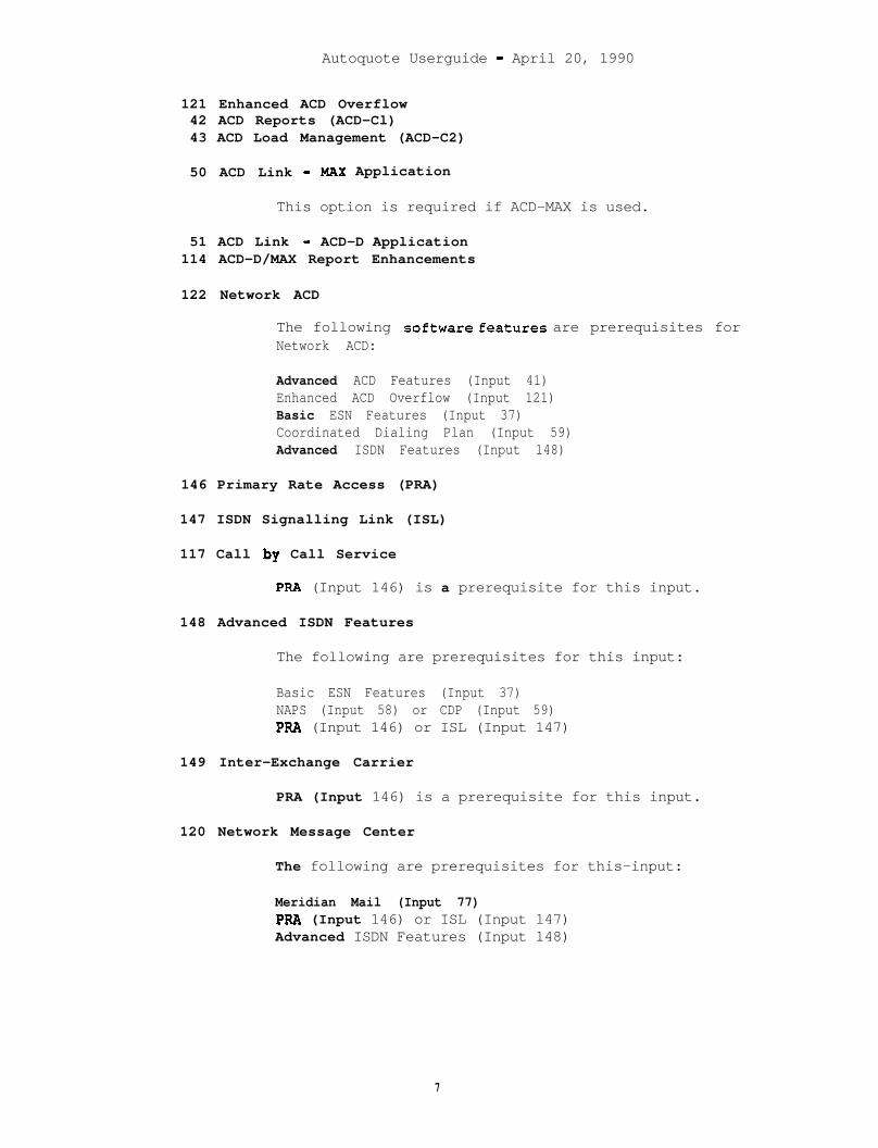
Autoquote Userguide - April 20, 1990
121 Enhanced ACD Overflow42 ACD Reports (ACD-Cl)43 ACD Load Management (ACD-C2)
50 ACD Link - MAX Application
This option is required if ACD-MAX is used.
51 ACD Link - ACD-D Application114 ACD-D/MAX Report Enhancements
122 Network ACD
The following SOftWare features are prerequisites forNetwork ACD:
Advanced ACD Features (Input 41)Enhanced ACD Overflow (Input 121)Basic ESN Features (Input 37)Coordinated Dialing Plan (Input 59)Advanced ISDN Features (Input 148)
146 Primary Rate Access (PRA)
147 ISDN Signalling Link (ISL)
117 Call by Call Service
PPA (Input 146) is a prerequisite for this input.
148 Advanced ISDN Features
The following are prerequisites for this input:
Basic ESN Features (Input 37)NAPS (Input 58) or CDP (Input 59)PRA (Input 146) or ISL (Input 147)
149 Inter-Exchange Carrier
PRA (Input 146) is a prerequisite for this input.
120 Network Message Center
The following are prerequisites for this-input:
Meridian Mail (Input 77)PRA (Input 146) or ISL (Input 147)Advanced ISDN Features (Input 148)
7
Autoquote Userguide - April 20, 1990
2.2.2 Phones, Lines, and Trunks
This input class consists of two categories of inputs: ports (lines andtrunks) and terminal devices (telephone sets). Ports inputs generallyaccept equipped and wired quantities. It is with wired inputs that thebuilt-in growth of a system is provisioned. PE cards' are quoted at theequipped level, all other items are quoted at the-wired level.Therefore, only PE cards must be added to grow a system from theequipped to the wired size.
2.2.2.1 Port Inputs
Phones, Lines, and Trunks port inputs are numbers l-43, 101-143, and171-178. Inputs 101-143 are for non-blocking ports. Input 101 (non-blocking) corresponds to input 1 (P.Ol), input 102 (non-blocking)corresponds to input 2 (P.Ol), etc.
.Unless otherwise noted, all port inputs accept three entries:
1. EuuinDed Ports Desired.2. Wired Ports Desired.
If no entry is made, this entry will default to the equippedquantity entered. The wired value cannot be less than theequipped value.
3. Traffic (CCS) Per Port.Maximum traffic allowed is 36 CCS. Traffic defaults thatare listed below in the Traffic Defaults Table, are for P.01Grade of Service (GOS) ports unless otherwise noted. Non-blocking port inputs default to 36 CCS for those entries notaffecting Digitone Receiver (DTR) requirements. Non-blocking inputs affecting DTR's default to the P.01 GOSvalue.
( Note that telephone sets are entered independently of the ports.
8
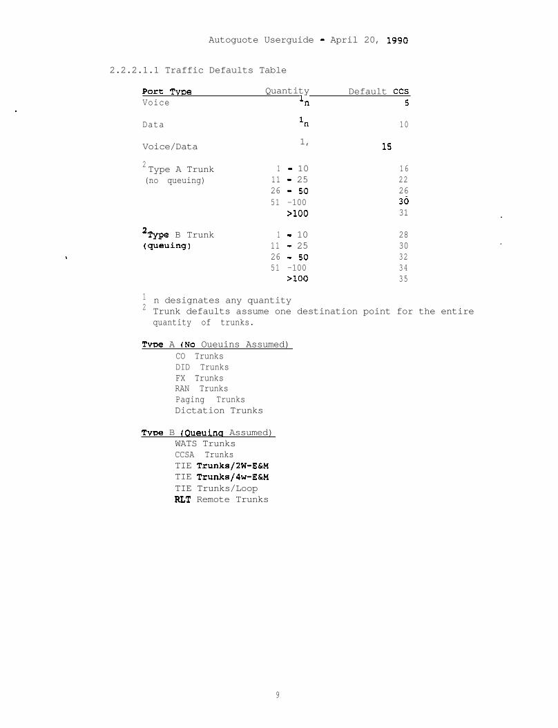
Autoguote Userguide - April 20, 1990
2.2.2.1.1 Traffic Defaults Table
Port TvDe QuantityVoice l*
Default CCS5
Data l* 10
Voice/Data 1, - 15
2 Type A Trunk 1 - 10 16(no queuing) 11 - 25 22
26 - 50 2651 -100 30
>lOO 31
2Type B Trunk(queuing)
.
1 - 10 2811 - 25 3026 - 50 3251 -100 34
>lOO 35
12n designates any quantityTrunk defaults assume one destination point for the entirequantity of trunks.
Type A (No Oueuins Assumed)CO TrunksDID TrunksFX TrunksRAN TrunksPaging TrunksDictation Trunks
TvDe B (Oueuina Assumed)WATS TrunksCCSA TrunksTIE Trunks/2W-E&MTIE Trunks/4w-E&MTIE Trunks/LoopRLT Remote Trunks
9
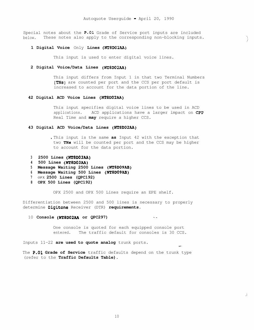
Autoquote Userguide - April 20, 1990
Special notes about the P.01 Grade of Service port inputs are includedbelow. These notes also apply to the corresponding non-blocking inputs.
1 Digital Voice Only Lines (NT8D02A.A)
This input is used to enter digital voice lines.
2 Digital Voice/Data Lines (NT8D02AA)
This input differs from Input 1 in that two Terminal Numbers(TNs) are counted per port and the CCS per port default isincreased to account for the data portion of the line.
42 Digital ACD Voice Lines (NT8D02AA)
This input specifies digital voice lines to be used in ACDapplications. ACD applications have a larger impact on CPUReal Time and may require a higher CCS.
43 Digital ACD Voice/Data Lines (NT8D02AA)
. This input is the same as Input 42 with the exception thattwo TNs will be counted per port and the CCS may be higherto account for the data portion.
3 2500 Lines (NT8D03AA)4 500 Lines (N!l!8003AA)5 Message Waiting 2500 Lines (NT8DOSAB)6 Message Waiting 500 Lines (NT8DOSAB)7 OPX 2500 Lines (QPC192)8 OPX 500 Lines (QPC192)
OPX 2500 and OPX 500 Lines require an EPE shelf.
Differentiation between 2500 and 500 lines is necessary to properlydetermine Digitone Receiver (DTR) requirements.
10 Console (NTSDOZAA or QPC297) .-
One console is quoted for each equipped console portentered. The traffic default for consoles is 30 CCS.
Inputs 11-22 are used to quote analog trunk ports. -
The P.01 Grade of Service traffic defaults depend on the trunk type(refer to the Traffic Defaults Table).
,;’
10
Autoquote Userguide - April 20, 1990
The following trunks are Type A (No Queueing Assumed)
11 CO Trunks (NT8D14AA)12 DID Trunks (NTSD14AA)14 FX Trunks (NT8D14AA)19 RAN Trunks (NT8D14AA)20 Paging Trunks (NT8D14AA or NT8D15AA)21 Dictation Trunks (NTBDlSAA)
The following trunk are Type B (Queueing Assumed)
13 WATS Trunks (NT8D14AA)15 CCSA Trunks (NT8DlSAA)
16 DX Trunks (QPC71)
DX Trunks require an EPE shelf.
17 TIE Trunks - E&M (NTBDlSAA)18 TIE Trunks - Loop (NT8D14AA)22 RLT- Release Link Trunks (QPC250)
Release Link Trunks are used for Remote CentralizedAttendant Service (CAS) applications. Software Input 27must be selected for these circuits to function. RLT Trunksrequire an EPE shelf.
DID (input 12), CCSA (input 15), and TIE (inputs 15,16,17) trunkincoming traffic may use Digitone signaling. This information will beprompted for in the Basic Information input class when setting up a newquote. All digitone traffic will affect the number of DigitoneReceivers (DTR's) provisioned.
The remaining entries are for data lines, and digital trunks.
23 Sync/Async CPU Terminations (QPC432)
This input is the same as input 28 with the exception of thetraffic default. The traffic default for CPU terminationswill correspond to Type B trunk values (Queueing assumed) .rsince they typically have greater usage than stationterminations.
24 Async Modem Pool Lines (QPC723 & NT8D03AA) ,--
Two physical ports are provisioned for this modem poolapplication-- one QPC723 RILC port and one NT8D03AA 500/2500port. The traffic is presented to the switching matrixtwice, therefore Autoquote will double the traffic inputwhen determining network requirements. The traffic defaultwill correspond to Type B Trunk values (Queueing assumed).
11
Autoquote Userguide - April 20, 1990
27 Sync/Async Modem Pool Lines (QPC432 & NTSDO3AA)
Two physical ports are provisioned for this modem poolapplication: one QPC723 RILC port and one NT8D03A.A 500/2SOOport. The traffic is presented to the switching matrixtwice, therefore Autoquote will double the traffic inputwhen determining network requirements. The traffic defaultwill correspond to Type B Trunk values (Queueing assumed).
28 Sync/Async Data Lines (QPC432). .
QPC432 data line cards provide access to the Meridian 1switching matrix for sync or async devices. An Async/SyncInterface Module (ASIM) or High-Speed Data Module (HSDM) is
used to interface RS-232 ports to QPC432 ports. An adaptercable may be used for a V.35 connection on the HSDM.
29 Async Data Lines (QPC430)
QPc430 data line cards provide access to the Meridian 1switching matrix for async devices. An Async InterfaceModule (AIM), Async Interface Logical Unit (AILU), or .Personal Computer Interface (PCI) card is used to interfaceRS-232 ports to QPC430 ports. Some devices may interfacedirectly to the QPC430 data line card using a compatibleRS-422 port.
30 MCDS Async Lines (QPC432,QPC397)
Multi-Channel Data System is a rack or cabinet mountedversion of async-only ADM’s, used primarily to interface toCPU ports. This input is used to provision the Meridian 1EPE (QPC432 data line card) as well as the MCDS hardware.The traffic default is 30 CCS.
31 CIM Lines(QPC432)
Although this input results in the same Meridian 1 hardwareprovisioning as input 28, the specific applicationrepresented is Coax Elimination and Switching using the Coax . 'Interface Module (CIM) to interface a coax terminal device.
32 MCCS Lines (QPC432,NT9N02) _-
This input represents the host/controller end of the CoaxElimination and Switching application. It is used toprovision the Meridian 1 PE (QPC432 data line card) as wellas the Multi-Channel Coax System (MCCS) hardware. Thetraffic default is 30 CCS.
12
Autoquote Userguide - April 20, 1880
35 RILC Data Lines (QPC723)
This data line card provides for direct RS-232 access to theswitching matrix. Using this card in a modem poolapplication will result in traffic being introduced into thesystem only once.
40 D!CI (QPC720)41 CPI (QPC720)
These input accept two entries.
1st entry is number desired. Equipped/wired quantities arenot used since DTI/CPI hardware is not Peripheral Equipment(=I. DTI/CPI cards interface directly to network loops andare housed in Common Equipment and/or Network Equipmentshelves.
2nd entry is traffic (in CCS) per channel. This entry willdefault to Type 0 trunk values. (Each DTI/CPI is treatedlike 24 trunks.)
A DTI/CPI link is essentially non-blocking since it interfacesdirectly to a network loop. There are no corresponding non-blocking DTI/CPI inputs.
171 PRI (QPC720 & QPC757)172 PRI (QPC720 & QPC757)173 PRI (QPC720 & QPC757)174 PRI (QPC720 & QPC757)175 PRI (QPC720 & QPC757)176 PRI (QPC720 & QPC757)177 PRI (QPC720 & QPC757)178 PRI (QPC720 & QPC757)
Each input corresponds to a different destination point; up toeight destinations can be selected. Differentiating betweendestinations is required to determine the required number ofD-Channel Interface cards. PRA (Software input 146) and PBXInterface (Base package) are prerequisites for this application.These inputs accept two entries.
1st entry is number desired. Equipped/wired quantities arenot used since PRI hardware is not Peripheral Equipment(PE) l PRI cards interface directly to network loops and arehoused in Common Equipment and/or Network Equipment shelves.
2nd entry is traffic (in CCS) per channel. This entry willdefault to Type B trunk values. (Each PRI is treated like24 trunks.)
13

Autoquote Userguide - April 20, 1990
Telephone Set Inputs
Phones, Lines, and Trunks inputs 51-100, and 206-281 are used forselecting terminal devices and accessories. All phone inputs accept oneentry, indicating the number of units desired. Please refer to thesample input sheet at the end of this section for the actual Telephoneset inputs.
Inputs 269, 270 and 271 are used to allow Modular Set Power overrides.Entering a 1 for Input 271, allows the number of 110 V transformers andpower boards to be entered using Inputs 269 and 270 respectively.
14
Autoguote Userguide - April 20, 1990
2.2.3 Miscellaneous/Memory
There is are common rules regarding the number of entries aMiscellaneous/Memory input may accept. Refer to the input sheet and theinformation provided below for the number,of entries each input accepts.
Information on the Miscellaneous/Memory inputs is included below. Notethat the input descriptions appear in the order of the Input Sheet andare not in numerical order.
1 Power Indicator
This input applies to the way in which the system will bepowered. Enter 1 for AC Power, 2 for DC using CustomerProvided Power, or 3 for DC using Rectifiers and BatteryBackup (input 9). If this input is set to 2, (DC usingCustomer Provided Power), no rectifiers will be included inthe quote.
9 Battery Backup
This entry accepts two entries.
The 1st entry is the number of hours of battery backupdesired. For Option 71 quotes, this input will be seof no entry is made. .
The 2nd entry is the battery type indicator: zero (0 )indicates Absolyte and one (1) indicates Lead Calciumbattery hardware.
: to 4
Please see Report 4 to determine battery backuprequirements. Note that no batteries will be included inthe quote.
10 UPS
This input is used to indicate the UPS vendor desired: one(1) for Exide, two (2) for, Best, or three (3) for Alpha.Please see Report 4 to determine UPS rating requirements.Note that the UPS system will not be included in the quote.
2 Hard Disk Drive --
Enter one (1) if desired, enter zerd (0) to remove fromquote. This option is available only on the Option 51, 61,and 71.
15
Autoquote Userguide - April 20, 1990
3 Emergency Transfer Units (ETU)
Enter the number desired. The NT8939AA ETU Assembly isprovisioned on all systems. Each one allows eight 500/2500phones to be connected to CO lines. Since this unit isexternal to the Meridian 1 cabinet, it does not impactsystem engineering.
4 Attendant Admin Overlay
Enter the number of Overlays desired.
5 Supervisory Console Functionality
This input only applies to Remote Peripheral Equipment (RPE)quotes. Enter one (1) for this input if the QPC297Supervisory Line Card should be quoted.
11 Pedestal/Top Cap Provisioning Indicator
This input applies to the Option 21 only. It is used tooverride the calculated Pedestal/Top Cap assembly to ahigher one. Zero (0) indicates that the most cost effective'Pedestal/Top Cap assembly will be provisioned; two (2)indicates that the Two-Module Pedestal will be the minimumprovisioned; four (4) indicates that the Four-ModulePedestal will be provisioned.
12 Rectifier/Power Cabinet (Options 51,61 only)
Enter one (1) to provision the Prime Power Cabinet Assembly.This cabinet houses up to four 50 Amp rectifiers to be usedin lieu of 30 Amp rectifiers.
14 CDR Usage (Outgoing,Incoming,Internal)
This input is used to calculate CPU Real Time impact of CDR.Enter one (1) to indicate either Outgoing, Incoming orInternal usage for CDR. As an example, the input 14/1,0,1indicates that the CDR will be used for Outgoing andInternal calls only. The default is 14/1,0,0 meaning thatCDR is limited to Outgoing calls only.
15 Code Restriction Route--
Enter the number of code restriction routes used in thesystem. This input is used for memory.
16 Speed Call Lists/l Digit17 Speed Call Lists/2 Digit18 Speed Call Lists/3 Digit
These inputs are used to calculate required P-Data for Speed Call Lists.They accept three entries:
: :
16
Autoquote Userguide - April 20, 1990
The 1st value is the number of lists desired.
The 2nd value is the number of entries per speed call list.The maximum is 10 for l-digit lists (input 16), 100 for 2-digit lists (input 17), 1000 for 3-digit lists (input 18).This entry will default to 7 digits for l-digit lists (input16) and 40 for a-digit and_3-digit lists (inputs 17,18).
The 3rd value is the number of digits per speed call list.The maximum allowed is 31 and the default value is 10 forall three inputs.
19 Data Modem
Enter the quantity desired.
20 Dual NTP Storage Sleeve
Enter the number of NTP storage sleeves desired. Eachstorage sleeve holds two NTP's. Typically four sleeves arerequired for a complete set of NTP~'s.
23 Average Holding Time
Enter the Average Holding Time per (P.01) call in seconds.Autoquote will set this input to 180 seconds if no entry ismade.
25 MCDS Cabinet
Enter 1 if MCDS cabinets are to be quoted to house the MCDSshelves. These shelves can housed in standard 19 inchracks.
27 Number of AD/SNR/LNR Entries
This input is prompted on every Meridian 1 model. It isused to calculate memory requirements for Auto-Dial, StoredNumber Redial, and Last Number Redial entries/keys in thesystem. This input accepts two entries. The 1st value isthe number of entries or keys assigned with these features.The 2nd value is digits per entry. The maximum is 31 andthe default is 16 digits.
-28 Number of Do-Not-Disturb Stations
This input is prompted when the Do-Not-Disturb feature isequipped. It is used to calculate memory requirements forfeature implementation. Enter the quantity desired.
17
Autoquote Userguide - April 20, 1990
29 Number of Dial Intercom Groups
This input is prompted when the Dial Intercom feature isequipped. It is used to calculate memory requirements'forfeature implementation. Enter quantity desired.
30 Number of Group Call Groups
This input is prompted when the Group Call feature isequipped. It is used to calculate memory requirements forfeature implementation. Enter quantity desired.
31 Nix&et of ACD Queues32 Number of ACD Agent Positions33 Number of ACD Auto-Terminate Trunk Routes34 Number of ACD Auto-Terminate Trunk Routes35 Number of ACD CRT's
Inputs 31, 32, and 34 are prompted when any ACD option group isequipped. Input 33 and 35 are prompted only if ACD-Cl or ACD-C2 isequipped. These inputs are used to calculate memory requirements forthe ACD application. All of these inputs accept two entries: 1st entryis equipped quantity, 2nd entry is wired quantity.
40 Number of Customers
The input indicates the number of customers desired. Amaximum number of 32 customers may be.entered.BARS (input 41) and Multi-Tenant (input 41) are implementedon a customer basis. Memory requirements are determinedusing Miscellaneous/Memory inputs 40-42 when applicable.
41 Number of Customers Equipping BARS
This input is prompted if the Multi-Customer and BARSfeatures are equipped. BARS is implemented on a customerbasis. This input is used to calculate memory requirementsfor the BARS application.
42 Number of Customers with tklti-Tenant Service Equipped
This input is prompted if the Multi-Customer andMulti-Tenant features are equipped. Multi-Tenant isimplemented on a customer basis. This input is used tocalculate memory requirements for the Multi-Tenantapplication.
43 Total Number of Tenants Equipped44 Total Number of Tenant Stations
These inputs are prompted if the Multi-Tenant feature is equipped. Theyare used to calculate memory requirements for Multi-Tenant application.
18
AutOqUOte Userguide - April 20, 1990
45 Number of ISDN Signalling Links
This input is used to select the number of ISDN SignalingLinks (ISL's) required. The ISL option (Software input 147)is a prerequisite for this input.
46 CE/Disk Drive Provisioning - Override
Applicable to the Meridian 1 Option 21 only, this input isused for Disk Drive placement.
There are two scenarios for housing the Disk Drive:0 = CE Placement in the CE/PE Module. _
1 = PE Placement in the CE/PE Module.
Autoquote will provision the Disk Drive in the CE shelfunless network requirements force it into PE placement. Theuser may force PE placement by entering a one (1) for thisinput.
47 Additional P-Data (kwords)
This input accounts for additional memory requirements.Values are entered in thousands of words; i.e. if a one (1)is entered, 1000 P-Data words are added.
48 Additional U-Data (kwords)
This input accounts for additional memory requirements.Values are entered in thousands of words: i.e. if a one (1)is entered, 1000 U-Data words are added.
49 Number of Call Party Name Display Entries
These inputs are prompted if the Call Party Name Displayfeature is equipped. They are used to calculate memoryrequirements for CPND application. This input accepts twoentries. The 1st value is the number of entries. The 2ndvalue is characters per entry. The default is 15characters.
50 Number of Auth Codes.
This input accepts two entries. Both are used to allocateP-Data for authorization codes. lst.ehtry is the number ofauthorization codes used in the system (maximum allowed is4096). 2nd entry is number of digits per authorization code(maximum is 14). The default value is 8 digits.
19
Autoquote Userguide - April 20, 1990
21 Additional SD1 Ports
Autoquote provisions the number of SD1 ports required tosupport software and maintenance (local and remote). Thisinput is used to specify additional SD1 ports for otherapplications such as SDI's to connect CRTfs for ACDsupervisors. One SD1 cable is provisioned for each SD1port. Autoquote does not determine cable connector type(M/M or F/F). The user must specify the connector type whenplacing the order.
37 Additional SD1 Ports for APL's
This is used to determine the number of SD1 ports requiredfor Application Processor Links. Only the quantity notincluded within AUX-Loaded models must be entered. (Referto the Introduction/Overview chapter for more information onthe AUX-Load mechanism.)
38 Additional Conference Cards for MOH/AWU
This input is prompted when Music-on-Hold and/or AutomaticWake-up features are equipped. It is used to specify thenumber of additional Conference Cards required to supportthese features. The Automatic Wake-up feature requires onededicated Conference Card per system. Music-on-Hold, on theother hand, may share a Conference Card with a normalconference traffic. The total number of Conference cardsrequired on any system depends on the specific application.
39 Additional ESDI Ports
Enhanced SD1 (ESDI) ports are used to support Command StatusLink (CSL) and ISDN/AP Link (The CSL provides the interfacefor Meridian Mail). This input is used to specify thenumber of additional ESDI ports required; i.e., ports inaddition to the ports required for Meridian Mail eitherAUX- Loaded or system integrated, and/or the default portsbased on software option selection. One ESDI port will beincluded when ISDN/AP software is quoted. Autoquote willalso include support for one ESDI when CSL software isquoted and no Meridian Mail application is quoted(integrated or AUX Loaded.) When Meridian Mail. is quoted,ESDI cards are generally provisioned via Meridian Mail basehardware packages. (Refer to the Introduction/Overviewchapter for more information on the AUX-Load mechanism.)
180 Additional Network Groups
This input applies to the Option 71 only. It is used toincrease the number of network groups calculated by theAutoquote. The maximum value is 4.
20
Autoquote Userguide - April 20, 1990
181 Additional Superloops182 Additional Non-blocking Superloops
These inputs are used to provide additional Superloops (NT8D04AA) to thesystem. The net amount of Enhanced Loops must be greater than or equalto the minimum required to maintain P.01 Grade of Service.
183 Additional Network Loops184 Additional Non-blocking Network Loops
These inputs are used to provide additional Enhanced Network Loops(QPC414) to the system. The number of Enhanced Loops must be greaterthan or equal to the minimum required to maintain P.01 Grade of Service.
190 Ringing Generator Provisioning Factor
Ringing Generators are required in IPE Shelves which supportAnalog Cards. The calculation to determine the number ofringing generators is as follows:Ringing Generators = % Analog Cards * Factor * PE Shelveswhere Factor defaults to 2. This input allows the user tooverride the default factor of 2 and enter another ifnecessary. The factor may not be less than 1.0.
99 Software Graduation Level Override
This input is used to directly enter the Software GraduationLevel desired. This input will override Miscellaneous Input100 as long as the input value is not less than the minimumlevel required. As an example, if the Equippedconfiguration equated to 5 Software Graduation Levels andthe Wired configuration equated to 8 Software GraduationLevels, this input could be used to request a level of 7, 9or any level not less than 5.
100 Software Graduation Level Indicator
This input is used to select the whether the SoftwareGraduation Level will be calculated using the Equipped orWired configuration. Enter zero (0) for Equipped or one (1)for Wired. The default is Equipped. Note that this inputwill not apply if-Input 99 is used.
101 Module Placement Indicator _-
This input only applies to Option 71 quotes. If one (1) isentered for this input, module positions for network groupswill be reserved for future growth.
21
, Autoquote Userguide - April 20, 1990
102 Cable Egress Indicator
This input is used to determine the way in which cables willbe wired out of modules. Enter one (1) for Bottom Egress,two (2) for Top Egress or three (3) for Top Egress withCable Tray Kit.
103 Earthquake Bracing Kit
Enter one (1) if Earthquake Bracing equipment is required.
145 TDR Unit
This unit applies to the Direct sales channel only. It isapplicable to the Meridian 1 Option 21, 51 and 61. Thisinput accepts three entries.
1st entry indicates the firmware package: one (1) for theBusiness package, two (2) for the Professional Billingpackage, and three (3) for the Lodging package.
2nd entry is the total number of calls made per month inthousands. For example, enter three (3) if 3000 calls permonth are to be supported. This value is used to size theTDR Unit. If no entry is made, the number of calls will bea function of the number of calls per station per month (3rdentry) .
3rd entry is the number of calls per station per month.This entry will default to 100. The number of calls perstation per month will be used to determine the total numberof calls per month if no entry is made for the 2nd value.
Inputs 150-156 are used to quote the Meridian Mail Optionand associated features.
150 Meridian Mail
The Meridian Mail Software package (Software input 77) is aprerequisite for this input. This input accepts threeentries:
1st entry is the number of voice processor ports desired.The maximum value allowed is 48. All entries will beconverted to the next voice processor port incrementavailable on the product (4,8,12,16,20,...,or 48 ports).
2nd entry is the total number of hours of voice storagedesired. The maximum value allowed is 240. All entrieswill be converted to the next voice storage incrementavailable on the product (5,11,24,36,...,or 240 hours).
;;i
22
Autoguote Userguide - April 20, 1990
3rd entry is number of registered users supported. Thisentry will determine the number of User Guides provided andreal time impact.
151 Meridian Mail Voice Menus
Enter the number of Voice Menu calls during the busy hour.Any value entered greater than zero will provision VoiceMenus Software. The number of voice menu calls during thebusy hour is requested to help determine CPU real timeimpact.
152 Meridian Mail Console Software
Enter one (1) if this option is desired.
153 Meridian Mail Access Development Software
Enter one (1) if this option is desired. Meridian MailConsole Software is a prerequisite for this'option.
155 Meridian Mail Networking Ports
Enter the number of ports desired to be used for networkingMeridian Mail Options together. Note that this input isused to provision the correct amount of Meridian MailNetworking Hardware and Modem Packages as well as NetworkingSoftware. The total number of actual Meridian Mail portsprovisioned is only indicated in Input 150.
156 Meridian Secured Messaging
Enter a one (1) if this option is desired.
169 CPlus Directory & Messaging PC Software
This input is used to specify the PC based CPLUS AttendantConsole Software. Enter the number of copies desired.
171 Meridian Manager - Work Order System
Enter one (1) to quote this option. Note that MeridianManager-Station Administration is included with the base--Meridian 1 software package.
172 Meridian Manager-Traffic Reporting
Enter one (1) to quote this option. Note that MeridianManager-Station Administration is included with the baseMeridian 1 software package.
23

Autoquote Userguide - April 20, 1990
Inputs 51-84 are used to quote non-blocking PE 'cards and modules. Eachinput accepts two entries: 1st entry is equipped quantity, 2nd entry iswired quantity. These inputs are required to specify exact quantitiesof hardware required for non-blocking application. These values cannotbe calculated by Autoquote since there is a possibility that some portsand/or some PE slots may be unusable in a non-blocking situation.Autoquote can determine the minimum required PE cards and shelves basedon port inputs. During the calculation process Autoquote will make sureall non-blocking PE quantities are not less than the minimum calculated.Refer to Non Blocking Applications, page 54.
123 Average Holding Time (non-blocking)
Enter the Average Holding Time per call in seconds.Autoquote will set this input to 180 seconds if no entry ismade.
24
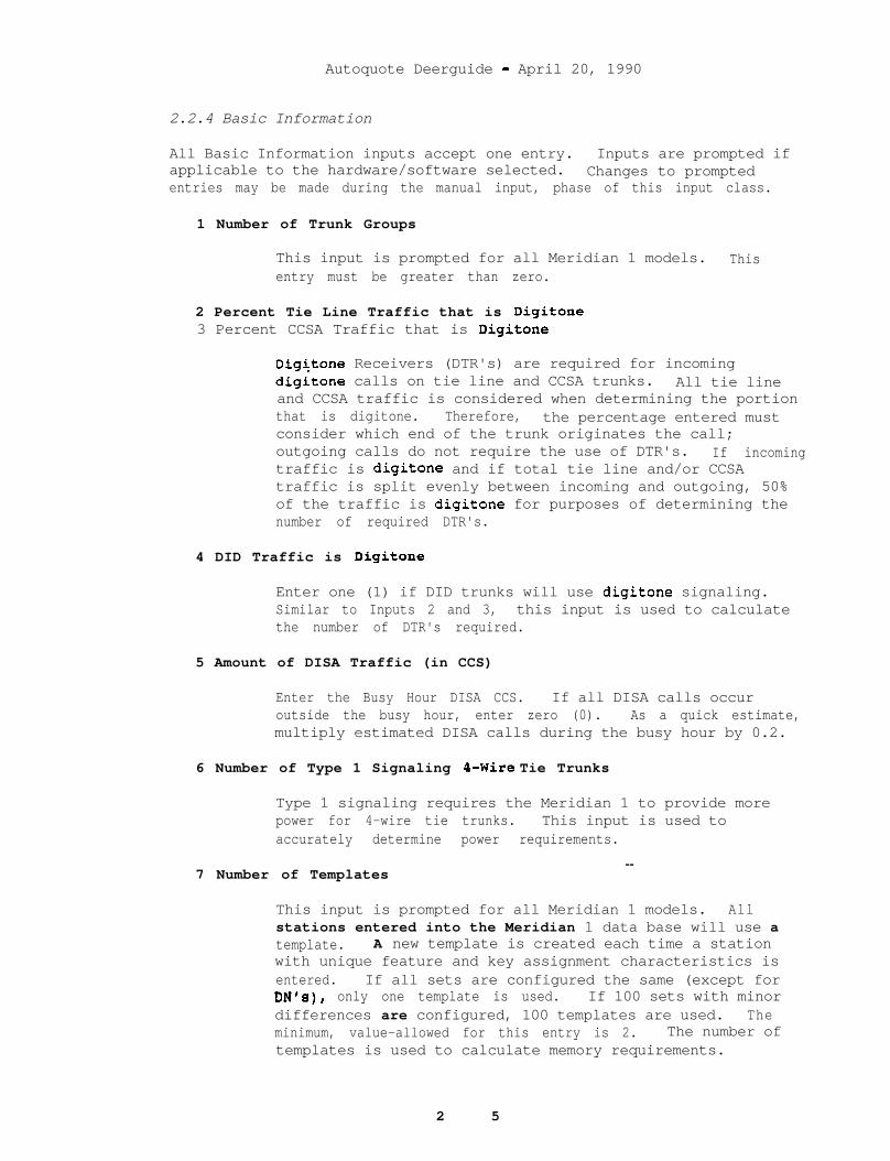
Autoquote Deerguide - April 20, 1990
2.2.4 Basic Information
All Basic Information inputs accept one entry. Inputs are prompted ifapplicable to the hardware/software selected. Changes to promptedentries may be made during the manual input, phase of this input class.
1 Number of Trunk Groups
This input is prompted for all Meridian 1 models. Thisentry must be greater than zero.
2 Percent Tie Line Traffic that is Digitone3 Percent CCSA Traffic that is Digitone
Digitone Receivers (DTR's) are required for incomingdigitone calls on tie line and CCSA trunks. All tie lineand CCSA traffic is considered when determining the portionthat is digitone. Therefore, the percentage entered mustconsider which end of the trunk originates the call;outgoing calls do not require the use of DTR's. If incomingtraffic is digitone and if total tie line and/or CCSAtraffic is split evenly between incoming and outgoing, 50%of the traffic is digitone for purposes of determining thenumber of required DTR's.
4 DID Traffic is Digitone
Enter one (1) if DID trunks will use digitone signaling.Similar to Inputs 2 and 3, this input is used to calculatethe number of DTR's required.
5 Amount of DISA Traffic (in CCS)
Enter the Busy Hour DISA CCS. If all DISA calls occuroutside the busy hour, enter zero (0). As a quick estimate,multiply estimated DISA calls during the busy hour by 0.2.
6 Number of Type 1 Signaling g-Wire Tie Trunks
Type 1 signaling requires the Meridian 1 to provide morepower for 4-wire tie trunks. This input is used toaccurately determine power requirements.
7 Number of Templates--
This input is prompted for all Meridian 1 models. Allstations entered into the Meridian 1 data base will use atemplate. A new template is created each time a stationwith unique feature and key assignment characteristics isentered. If all sets are configured the same (except forDN's), only one template is used. If 100 sets with minordifferences are configured, 100 templates are used. Theminimum, value-allowed for this entry is 2. The number oftemplates is used to calculate memory requirements.
2 5
Autoguote Userguide - April 20, 1990
8 Number of Autovon Trunks
This input is used to calculate the additional memoryrequirements for Autovon trunks.
9 Percent DTI Traffic that is Digitone
Since DTI can function as a tie line or DID trunk, digitonesignaling may be used. Enter percent of total traffic thatis incoming digitone. See explanations for inputs 2 and 4for more information.
10 Number of DTI/PRI Tie Lines
Enter the number of DTI/PRI Tie Lines expected in theconfiguration. This input is used to determine CPU RealTime impact.
26

Autoquote Userguide - April 20, 1990
3. ENGINEERING/PROVISIONING
.
This section covers the Engineering/Provisioning rules used ingenerating Meridian 1 configurations. -
The following sections are included:
Software ProvisioningPeripheral Equipment Cards And ModulesNetwork,Loop EngineeringSDI/ESDI/DCHI/CONFERENCE/TDS ProvisioningPRIjDTI/CPI ProvisioningCommon Equipment Card Placement RulesModule And Column ProvisioningPower .MemoryReal TimeNon-Blocking ApplicationsMeridian MailRemote Peripheral Equipment (RPE)
27

Autoquote Userguide - April 20, 1990
3.1 SOFTWARE PROVISIONING
The following is a list of software packages and the software optionsthat are included in each package. Packages are selected by enteringthe corresponding Software Inputs. Please refer to the Software sectionof the input sheet at the end of this section.
28
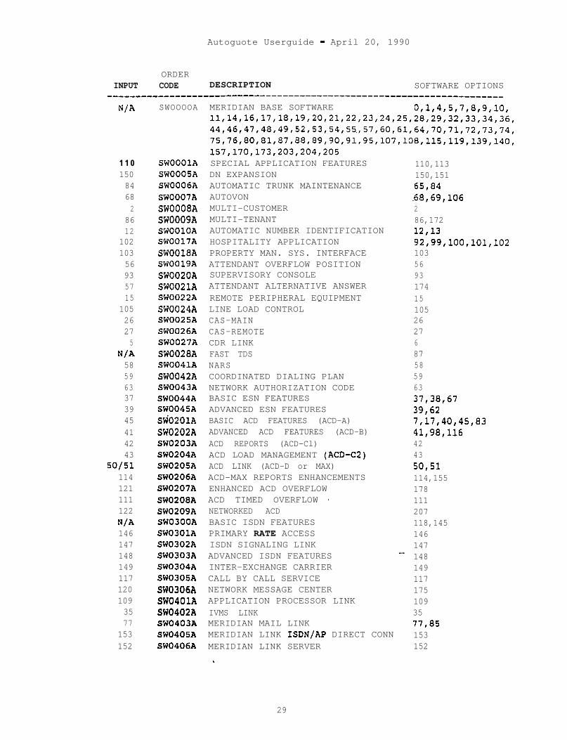
Autoguote Userguide - April 20, 1990
ORDERINPUT CODE DESCRIPTION SOFTWARE OPTIONS
____________----------------------------------------------------------
N/A SWOOOOA
1 1 0 SWOOOlA150 SWOOOSA84 SW0006A68 SW0007A2 SW0008A
86 SW0009A12 SWOOlOA
102 SW0017A103 SW0018A56 SW0019A93 SW0020A57 SW0021A15 SW0022A
105 SW0024A26 SW0025A27 SW0026A5 SW0027A
N/A SW0028A58 SW0041A59 SW0042A63 SW0043A37 SW0044A39 SW0045A45 StiO201A41 SW0202A42 SW0203A43 SW0204A
so/51 SW0205A114 SW0206A121 SW0207A111 SW0208A122 SW0209AN/A SW0300A146 SW0301A147 SW0302A148 SW0303A149 SW0304A117 SWO305A120 SW0306A109 SW0401A35 SW0402A77 SW0403A
153 SW0405A152 SW0406A
MERIDIAN BASE SOFTWARE 0,1,4,5,7,8,9,10,11,14,16,17,18,19,20,21,2,2,23,24,25,28,29,32,33,34,36,44,46,47,48,49,52,53,54,55,57,60,61,64,70,71,72,73,74,75,76,80,81,87,88,89,90,91,95,107,108,115,119,139,140,157,170,173,203,204,205SPECIAL APPLICATION FEATURESDN EXPANSIONAUTOMATIC TRUNK MAINTENANCEAUTOVONMULTI-CUSTOMERMULTI-TENANTAUTOMATIC NUMBER IDENTIFICATIONHOSPITALITY APPLICATIONPROPERTY MAN. SYS. INTERFACEATTENDANT OVERFLOW POSITIONSUPERVISORY CONSOLEATTENDANT ALTERNATIVE ANSWERREMOTE PERIPHERAL EQUIPMENTLINE LOAD CONTROLCAS-MAINCAS-REMOTECDR LINKFAST TDSNARSCOORDINATED DIALING PLANNETWORK AUTHORIZATION CODEBASIC ESN FEATURESADVANCED ESN FEATURESBASIC ACD FEATURES (ACD-A)ADVANCED ACD FEATURES (ACD-B)ACD REPORTS (ACD-Cl)ACD LOAD MANAGEMENT (ACD-C2)ACD LINK (ACD-D or MAX)ACD-MAX REPORTS ENHANCEMENTSENHANCED ACD OVERFLOWACD TIMED OVERFLOW 7NETWORKED ACDBASIC ISDN FEATURESPRIMARY RATE ACCESSISDN SIGNALING LINKADVANCED ISDN FEATURESINTER-EXCHANGE CARRIERCALL BY CALL SERVICENETWORK MESSAGE CENTERAPPLICATION PROCESSOR LINKIVMS LINKMERIDIAN MAIL LINKMERIDIAN LINK ISDN/AP DIRECT CONNMERIDIAN LINK SERVER
110,113150,15165,84-68,69,106286,17212,1392,99,100,101,102103569317415105262768758596337,38,6739,627,17,40,45,8341,98,1164243so,51114,155178111207118,1451461471481491171751093577,85153152
29
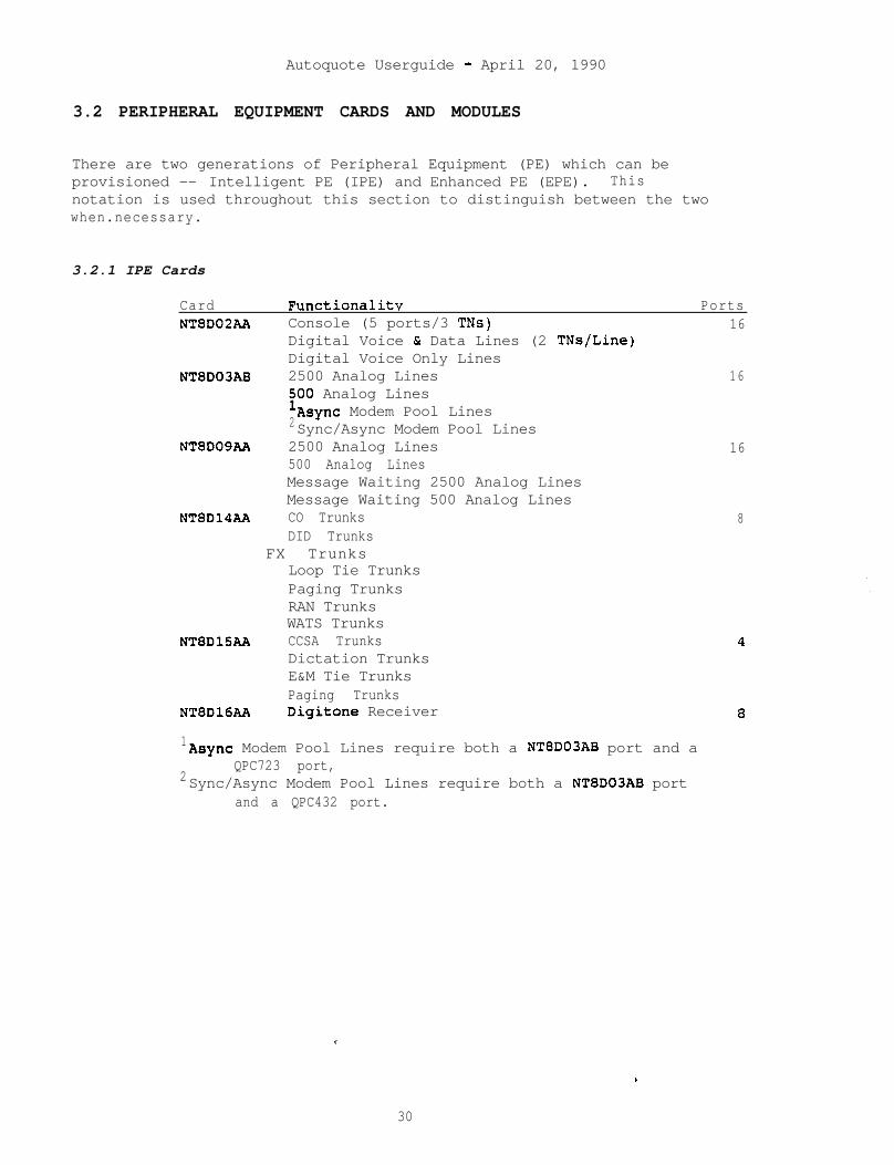
Autoquote Userguide - April 20, 1990
3.2 PERIPHERAL EQUIPMENT CARDS AND MODULES
There are two generations of Peripheral Equipment (PE) which can beprovisioned -- Intelligent PE (IPE) and Enhanced PE (EPE). Thisnotation is used throughout this section to distinguish between the twowhen.necessary.
3.2.1 IPE Cards
Card Functionalitv PortsNT8D02AA Console (5 ports/3 TNs) 16
Digital Voice & Data Lines (2 TNs/Line)Digital Voice Only Lines
NT8D03AB 2500 Analog Lines 165100 Analog Lines
2Async Modem Pool LinesSync/Async Modem Pool Lines
NT8D09AA 2500 Analog Lines 16500 Analog LinesMessage Waiting 2500 Analog LinesMessage Waiting 500 Analog Lines
NT8D14AA CO TrunksDID Trunks
FX TrunksLoop Tie TrunksPaging TrunksRAN TrunksWATS Trunks
NT8DlSAA CCSA TrunksDictation TrunksE&M Tie TrunksPaging Trunks
NT8D16AA Digitone Receiver
8
1Async Modem Pool Lines require both a NT8D03AB port and a
2QPC723 port,
Sync/Async Modem Pool Lines require both a NT8D03AB portand a QPC432 port.
V .
30
.

Autoquote Userguide - April 20, 1990
3.2.2 EPE Cards
Card Functionalitv PortsQPC71 DX Signalling Trunks 2QPC192 OPX 2500 Lines 4
OPX 500 LinesQPC250 RLT - Remote Trunks 4QPC297 Supervisory Line Card 4QPC432 CIM Lines .4
MCCS LinesMCDS Async LinesMCDS High Speed LinesSync/Async CPU Terminations;ync/Async DataSync/Async Modem Pool Lines
QPC430 Async Data LinesQPC422QPC723 Tone DetectorAsync Modem Pool Lines
RILC Data Lines
424
1 Async Modem Pool Lines require both a NT8D03AB port and a
2QPC723 port.
Sync/Async Modem Pool Lines require both a NT8D03AB portand a QPC432 port.
Autoquote optimizes the number of PE cards required by assigningmultiple types of ports on the same card. For example:
Unused Message Waiting (NT8D09AA) ports are used for 500/2500 and DataAnalog lines before the number of Analog (NT8D03AA) card are calculated.
Unused Universal Trunk (NT8D14AA) ports are used for CO, WATS, FX andPaging lines before,the number of XCOT and E&M (NT8DlSAA) cards arecalculated.
3.2.3 Digitone Receivers
Digitone Receivers (DTR's) interpret all digitone signals for the SL-1CPU. The number of DTR cards is determined in g three step procedure:
1) Calculate DTR traffic.2) Determine the DTR ports needed to support DTR traffic.3) Calculate DTR cards to accommodate required-DTR ports.
31
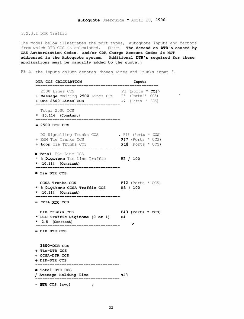
Autoquote Userguide - April 20, 1990
3.2.3.1 DTR Traffic
The model below illustrates the port types, autoquote inputs and factorsfrom which DTR CCS is calculated. (Note: The demand on DTR's caused byCAS Authorization Codes, and/or CDR Charge Account Codes is NOTaddressed in the Autoquote system. Additional DTR's required for theseapplications must be manually added to the quote.j
P3 in the inputs column denotes Phones Lines and Trunks input 3.
DTR CCS CALCULATION Inputs---------------------------------------------------
2500 Lines CCS P3 (Ports * CCS)+ Message Waiting 2500 Lines CCS PS (Ports'* CCS)+ OPX 2500 Lines CCS P7 (Ports * CCS)-----------------------------------Total 2500 CCS
* 10.114 (Constant)-----------------------------------= 2500 DTR CCS
.
DX Signalling Trunks CCS . P16 (Ports * CCS)+ E&M Tie Trunks CCS P17 (Ports * CCS)+ Loop Tie Trunks CCS P18 (Ports * CCS)-----------------------------------= Total Tie Line CCS* % Digitone Tie Line Traffic 82 / 100* 10.114 (Constant)-----------------------------------= Tie DTR CCS
CCSA Trunks CCS P12 (Ports * CCS)* % Digitone CCSA Traffic CCS B3 / 100* 10.114 (Constant)-----------------------------------= CCSA DTR CCS
DID Trunks CCS P40 (Ports * CCS)* DID Traffic Digitone (0 or 1) B4* 2.5 (Constant) /-----------------------------------= DID DTR CCS
2500-DTR CCS+ Tie-DTR CCS+ CCSA-DTR CCS+ DID-DTR CCS-----------------------------------= Total DTR CCS/ Average Holding Time M23-----------------------------------= DTR CCS (avg) *,
32
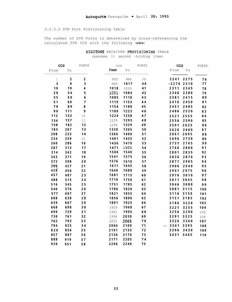
AutOquOte Userguide - April 20, 1990
3.2.3.2 DTR Port Provisioning Table
The number of DTR Ports is determined by cross-referencing thecalculated DTR CCS with the following table:
DIGITONE RECEIVER PROVISIONING TABLE(assumes 11 second -holding time)
ccs PORTS ccs PORTSFrom To From To
------------------- -------------------1 2 2 952 984 393 9 3 985 1 0 1 7 4 0
1 0 1 9 4 1 0 1 8 1050 4 12 0 3 4 5 1051- 1 0 8 4 4 23 5 5 0 6 1 0 8 5 1 1 1 8 4 35 1 6 9 7 1 1 1 9 1 1 5 3 4 47 0 8 9 8 1 1 5 4 1 1 8 8 4 59 0 1 1 1 9 1 1 8 9 1 2 2 3 4 6
1 1 2 1 3 3 10 1 2 2 4 1 2 5 8 4 71 3 4 1 5 7 11 1259 1 2 9 3 4 81 5 8 1 8 2 1 2 1294 1 3 2 9 4 91 8 3 2 0 7 1 3 1 3 3 0 1 3 6 5 5 02 0 8 2 3 3 1 4 1 3 6 6 1 4 0 0 5 12 3 4 2 5 9 15 1 4 0 1 1 4 3 5 5 22 6 0 2 8 6 1 6 1 4 3 6 1 4 7 0 5 32 8 7 3 1 3 1 7 1 4 7 1 1505 5 43 1 4 3 4 2 1 8 1 5 0 6 1 5 4 0 5 53 4 3 3 7 1 1 9 1 5 4 1 1 5 7 5 5 63 7 2 3 9 8 2 0 1 5 7 6 1 6 1 0 5 739q 4 2 7 2 1 1 6 1 1 1 6 4 5 5 84 2 8 4 5 6 2 2 1 6 4 6 1 6 8 0 5 94 5 7 4 8 7 2 3 1 6 8 1 1 7 1 5 6 04 8 8 5 1 5 2 4 1 7 1 6 1 7 5 0 6 15 1 6 5 4 5 2 5 1 7 5 1 1 7 8 5 6 25 4 6 5 7 6 2 6 1 7 8 6 1 8 2 0 6 35 7 7 6 0 7 2 7 1 8 2 1 1 8 5 5 6 46 0 8 6 3 8 2 8 1 8 5 6 1 8 9 0 6 56 3 9 6 6 7 2 9 1 8 9 1 1 9 2 5 6 66 6 8 6 9 8 3 0 1926 1 9 6 0 6 76 9 9 7 2 9 3 1 1961 1 9 9 5 6 87 3 0 7 6 1 3 2 1996 2 0 3 0 6 97 6 2 7 9 3 3 3 2031 .2065 7 07 9 4 8 2 5 3 4 2 0 6 6 2 1 0 0 7 18 2 6 8 5 6 3 5 2 1 0 1 2 1 3 5 7 28 5 7 8 8 7 3 6 2 1 3 6 2 1 7 0 7 38 8 8 9 1 9 3 7 2 1 7 1 2 2 0 5 7 49 2 0 9 5 1 3 8 2 2 0 6 2 2 4 0 7 5
ccs PORTSFrom To
2 2 4 1 2 2 7 5 7 6- 2 2 7 6 2 3 1 0 7 72 3 1 1 2 3 4 5 7 82 3 4 6 2 3 8 0 7 92 3 8 1 2 4 1 5 8 02 4 1 6 2 4 5 0 8 12 4 5 1 2 4 8 5 8 22 4 8 6 2 5 2 0 8 32 5 2 1 2 5 5 5 8 42 5 5 6 2 5 9 0 8 52 5 9 1 2 6 2 5 8 62 6 2 6 2 6 6 0 8 72 6 6 1 2 6 9 5 8 82 6 9 6 2 7 3 0 8 92 7 3 1 2 7 6 5 9 02 7 6 6 2 8 0 0 9 12 8 0 1 2 8 3 5 9 22 8 3 6 2 8 7 0 9 32 8 7 1 2 9 0 5 9 42 9 0 6 2 9 4 0 9 52 9 4 1 2 9 7 5 9 62 9 7 6 3 0 1 0 9 73 0 1 1 3 0 4 5 9 83 0 4 6 3 0 8 0 9 93 0 8 1 3 1 1 5 1 0 03 1 1 6 3 1 5 0 1 0 13 1 5 1 3 1 8 5 1 0 23 1 8 6 3 2 2 0 1 0 33 2 2 1 3 2 5 5 1 0 43 2 5 6 3 2 9 0 1053 2 9 1 3 3 2 5 1063 3 2 6 3 3 6 0 1 0 7
- - 3 3 6 1 3 3 9 5 1 0 83 3 9 6 3 4 3 0 1 0 93 4 3 1 3 4 6 5 1 1 0
3 3
Autoquote Userguide - April 20, 1990
3.2.3.3 DTR Cards
The number of DTR Cards required (NT8D16AA) is calculated by dividingtotal DTR Ports by 8 except on the Option 21. The Option 21 has 8 DTRports in the base Network/Controller Card. These are used before anyNTSD16AA are added. Example:
Option 21
DTR Cards = Round Up [(DTR Ports - 8)/(8 Ports Per DTR Card)]
Options 51,61,71
DTR Cards = Round Up [(DTR Ports)/(8 Ports Per DTR Card)]
3.2.4 Tone Detector
A tone detector (QPC422) is provisioned if Automatic Trunk Maintenance(ATM) software is requested. The QPC422 requires an EPE shelf.
3.2.5 IPE Modules
IPE shelves have 16 slots for cards plus one slot for a RingingGenerator and one Slot for a controller card. There are four 4-slotsegments in each IPE shelf.
The Option 21 has one dedicated 10 slot IPE shelf in the base module.This shelf has no segmentation.
3.2.6 EPE Modules
EPE shelves have 10 Slots for PE cards plus one slot for a RingingGenerator and one Slot for a QPC659 Buffer. There are two 5-Slotsegments in each EPE shelf.
3.2.6.1 Controller Cards
An NT8DOlAD Controller 2 is provisioned for IPE shelves supported by 2or less Superloops. An NT8DOlAC~Controller 4 is provisioned for IPEshelves supported by 3 or 4 Superloops. A QPC659 Dual Loop suffer isused for all EPE shelves.
3.2.6.2 Ringing Generators
Ringing Generators (NT8D21AAINT7D03AA) are required in all IPE and PEshelves which house analog line cards (NT8D03AA, NT8DOSAA for IPE andQPC192 for EPE). The NT8D21AA is provisioned for AC powered systems andthe NT7D03AA is provisioned f@r DC systems.
34

Autoguote Userguide - April 20, 1990
To determine the quantity of ringing generators the followingcalculation is used for IPE and EPE shelves individually.
Ringing Generators = (% Analog) * Factor * (PE Modules)
% Analog Cards = Analog Cards/PE Slots.Factor defaults to 2.0
This calculation allows for even distribution of Analog Cards whileminimizing the number of Ringing Generators which must be purchased.The user has the option to use a Factor other than the default of 2.0(Miscellaneous/Memory Input 190). A higher factor will yesult.in morePE shelves containing Ringing Generators.
The Option 21 has a 10 slot IPE shelf in the base module which getsringing current from the CE/PE Power supply and therefore does notrequire a Ringing Generator.
35
Autoquote Userguide - April 20, 1890
3.3 NETWORK LOOP ENGINEERING
This section covers the rules used for provisioning network loops forMeridian 1 Systems. Models (Option 21, 51, 61 and 71) are onlymentioned if a rule is different for a particular model.
3.3 -1 Calculating Network Loops
There are two types of network loops: Superloop (NT8D04AA) and EnhancedLoop (QPC414). The Superloop (NT8D04AA) supports the traffic in IPEmodules. The Enhanced Loop (QPC414) supports the traffic in EPE modulesand is also required for Meridian Mail and applications of Primary RateInterface (PRI), Digital Trunk Interface (DTI), and Computer to PBXinterface (CPI).
Separate calculations for the following are required to provisionnetwork loops.
Option 21IPE Modules P.01 GOSEPE Modules P.01 GOSMeridian MailPRI,DTI,CPINon-blocking
3.3.2 Option 21 Special Case
The Option 21 base module contains a combination network/controller cardwhich is dedicated to the 10 slot IPE shelf in that module. There is nonetwork loop engineering required for this loop as it will support alltraffic requirements of the 10 slot shelf.
3.3.3 IPE Modules (P.01 GOS)
Superloop requirements to support IPE modules is determined from thetotal IPE modules CCS and the total number of IPE modules:
The P.01 GOS capacity for a Superloop is 3500 CCS, 120 time slots.
A maximum of two IPE modules may be supported by a singleSuperloop.
--The number of Superloops required to support IPE modules is the greaternumber of the following calculations:
Sunerloons Reouired to SunDort Traffic (P.01 GO.51
Roundup( (Total IPE CCS) / (3500 CCS/Superloop) ]or
SuDerlooDs Reouired to SuDoort.IPE Modules:
Roundup[ (Number of IP$ Modulk) / (2 Modules/Superloop) ]
36
Autoquote Userguide - April 20, 1990
3.3.4 EPE MODULES (P.O1 GOS)
Enhanced Loop requirements to support EPE modules is determined from thetotal EPE modules CCS and the total number of modules:
The P.01 GOS capacity for an Enhanced Loop is 700 CCS, 30 timeslots. 700 CCS is being used for-Enhanced Loops.as opposed to theprevious 660 CCS because these loops will support a low number ofterminations.
The QPC414 contains two Enhanced Loops.
A maximum of two EPE modules may be supported by a single EnhancedLoop.
The number of enhanced loops required to support EPE modules is thegreater number of the following calculations:
Enhanced LOODS Reuuired to support EPE traffic (P.01 GOS):
Roundup[ (Total EPE CCS) / (700 CCS/Enhanced Loop) ]or
Enhanced LOODS Reuuired to suoport EPE modules (P.01 GOS):
Roundup[ (Number of IPE Modules) / (2 Modules/Enhanced Loop) ]
The number of Enhanced Network Cards (QPC414) required is calculated bydividing the number of Enhanced Loops by two:
Enhanced Network Cards Reouired to SuoDort EPE traffic (P.01 Gas)
Roundup( (Required Enhanced Loops) / 2 ]
3.3.5 Network Segmentation
The IPE shelves contain four 4-slot segments. One Superloop can supportfrom one to four segments per IPE module and up to a maximum of two IPEmodules.
The EPE shelves contain two 5-slot segments. An enhanced loop cansupport one or two segments per EPE module and up to a maximum of two--EPE modules.
The assignment of segments to loops for both IPE and EPE modules isaccomplished by:
a) trying to achieve even distribution (i-e same number ofsegments assigned to all loops)
b) if even distribution is not possible, the next choice is tochoose the quantity of loops and segments per loop which
37
Autoquote Userguide - April 20, 1990
gives the best distribution possible.
In case b, Autoquote will display a warning message on the reportsindicating that an even distribution of segments to loops was notpossible. The user has the option to do a manual assignment anddetermine that a P.01 GOS can be obtained with the uneven distributionor add additional network loops to make the distribution even.
3.3.6 Meridian Mail Loops
Each Meridian Mail Voice Channel requires 28 CCS of traffic capacity onan Enhanced Loop.
If the total traffic requirement for Meridian Mail does not increase thetotal number of network loops required then Meridian Mail traffic isassumed to be "shared" with PE shelf traffic.
If the total traffic requirement for Meridian Mail does increase thetotal number of network loops required, then the additional networkloops are assumed to be "dedicated" to Meridian Mail.
The 28 CCS per Voice Channel equates to one network loop being requiredfor every 24 Voice Messaging Channels.
3.3.7 PRI/DTI/CPI
One Enhanced traffic loop (2 per QPC414) is required to support aPRI/DTI/CPI link. No traffic engineering is required since each channelwill always have access to a timeslot on the network loop (Refer toSection , PRI/CPI/DTI Provisioning).
3.3.8 Non Blocking
Superloops and Enhanced Loops for Non Blocking applications arededicated Non Blocking only (Refer to Non Blocking Applications, page54:
38
Autoquote Userguide - April 20, 1990
3.4 SDI/ESDI/DCHI/CONFERENCE/TDS PROVISIONING
3.4.1 SDI Provisioning:
3.4.1.1 SD1 Ports:
Each system requires a minimum of four ports to serve the following:system monitor, local maintenance, remote maintenance, and CDR list. Inaddition each of the following inputs provisions an additional SD1 port.
INPUT CLASS NUMBER-_______----------------------------------------------CDR Link (CDR Mag Tape) SOFTWARE 5ACD Load Management (ACD-C2) SOFTWARE 43ACD Link (ACD-D) SOFTWARE 50Meridian Manager Traffic MISC/MEM 172
The total number of SD1 ports quoted is the sum of the four requiredports, the additional required ports noted above, and additional portsrequested via Miscellaneous/Memory input 21.
3.4.1.2 SD1 Cards:
There is one SD1 port on the Option 21A and Option 21 CPU (QPC687) card.There is also one SD1 port on each DCHI (QPC757) card. If more SD1ports are required than are available on the CPU and DCHI cards, thanSD1 Paddle Boards may be provisioned.
Each SD1 Paddle Board (NT8DQlA.A) provides two SD1 ports. They arequoted in the AS1052 2-Port Paddle Board Assembly and are housed on the arear of the CE/PE or CE/NE modules (no common equipment slots are used).The maximum number of SD1 Paddle Boards provisioned depends on thesystem type.
Svstem Maximum SD1 Paddle BoardsOption 21A 2Option 21 3Option 51 2Option 61 4Option 71 0
4If the maximum SD1 Paddle Boards is provisioned and-more SD1 ports arestill required, then four port SD1 cards (QPC84lj are quoted. Thesecards are provisioned in the AS1051 4-Port SD1 Assembly and are housedin common equipment slots.
3.4.1.3 SD1 Cables:
One 48ft cable is provisioned for each CDR List and/or CDR Linkapplication. If a SD1 Paddle Board is quoted the NT8D93AW isprovisioned, otherwise the NT8D95AW is used.
39
Autoquote Userguide - April 20, 1ggCI
One 16ft cable is provisioned for each remaining SD1 port. The NTBD93AJis provisioned for SD1 Paddle Boards and the NT8D95AJ is provisioned forCPU, DCHI, and SD1 cards.
3.4.2 ESDI Provisioning:
ESDI ports are determined by software options that require ESDI portsand engineering adjustments made to inputs. The following softwareoptions require one ESDI port: Command and Status Link (77), andISDN/AP Third Party Vendor (153).
Each ESDI Card (QPC513) provides two ESDI ports. They are provisionedas additional equipment except when included in a Meridian Mailassembly.
3.4.3 DCHI Provisioning:
DCHI Cards are provisioned based on PRI inputs. One card is requiredfor every 16 PRI links serving a particular destination. For example,if destination A needs three links and destination B needs nineteenlinks, a total of three DCHI cards is required. A maximum of eight DCHIcards may be configured.
3.4.4 Conference/TDS Card Provisioning: .
The quantity of Conference/TDS (NT8D17AA) cards quoted is the minimumnumber of Conference cards required by the system. As noted below, theminimum number of Conference cards depends on system model and size. *
Svstem Minimum Conference Cards21 151 161 271 - 1 Group 271 - 2 Groups 471 - 3 Groups 671 - 4 Groups 771 - 5 Groups 9
4Additional Conference cards requested by Miscellaneous/Memory~ &put 38will be provisioned as QPC444 Conference cards.
, :
40
Autoquote Userguide - April 20, 1990
3.5 PRI/DTI/CPI PROVISIONING
3.5.1 General Information
Software RequirementsPBX Software is a prerequisite for all three applications.PRA Software is a prerequisite for PPA applications.
Traffic EngineeringOne Enhanced traffic loop (QPC414) is required to support aPRI/DTI/CPI link. No traffic engineering is required since eachchannel will always have access to a timeslot on the network loop.
General ProvisioningThe number of links provisioned corresponds to the quantitiesselected via the following Lines, and Trunks inputs:
DTI - Input 40CPI - Input 41PRI - Inputs 171-178
3.5.2 Hardware
PRIThe QPC720 Primary Rate Interface, QPC757 D-Channel Interface, andthe QPC471 Clock Controller are the primary hardware componentsused in PRA applications. The QPC720 is also used in DTI/CPIapplications. The QPC720 is a double wide card and requires twoadjacent Common Equipment card slots.
Clock ControllerThe QPC471 Clock Controller(s) is provisioned when PRA and/or DTI
DCHI
DTI
CPI
is quoted. Only one(Options 21 and 51),(Options 61 and 71).
The QPC757 D-Channel
is required for non-redundant systemstwo are required for redundant systems
Interface (DCHI) is provisioned for every 16PRI links terminating at the same destination, and one isprovisioned for each ISDN Signaling Link. A maximum of eightQPC757 DCHI's can be provisioned on a system.--
The QPC720 and the QPC471 are the primary hardware components usedin DTI applications.
The CPI application uses the QPC720 only; the QPC471 is notrequired.
41
Autoguote Userguide - April 20, 1990
PRI/DTI/CPI Expansion (Network) ModulesAdditional network modules can be provisioned to house the QPC720cards on all system options. Each module can support up to 6QPC720 cards.
Clock Controller CablesThe following cables are provisioned when PRI and/or DTI arequoted:
NT8D79AF (PRI to Clock Controller)One for each PRI/DTI card, up to a maximum of two onnon-redundant systems (Options 21 and 51) four on redundantsystems (Options 61 and 71).
NT8D75AD (Clock Controller to Clock Controller)One for redundant systems (Options 61 and 71) only.
.:
42
Autoquote Userguide - April 20, 1990
3.6 COMMON EQUIPMENT CARD PLACEMENT RULES
The following is a list of CE cards that must be placed. Other CE cardsthat have fixed slot placement are not mentioned.
NT8D04AAQPC414QPC720QPC471QPC757QPC814QPC513NT8D17AA
SuperloopEnhanced Network LoopPRIClock ControllerDCHISD1ESDIConference/TDS
3.6.1 General Rules:
Each Superloop takes one physical slot and one virtual slot on allOptions except the Option 21. This is required because the Superloopuses 4 consecutive network buses. (e.g. O-3,4-7,8-11). This meansthat no card that requires a network bus may be placed in a virtual slotof a Superloop, but other cards can be placed in the virtual slot. Iftwo Superloops are placed in such a way that the two virtual slot areadjacent, then double wide cards (e.g. QPC720) that only require poweror signalling can be placed between the Superloops.
On the Option 21 Superloops may be placed in adjacent slots. This isthe only exception to the above rules on Superloops.
The QPC720 PRI Card and the NT8D68AA Floppy Disk Unit are double widecards and require two adjacent slots.
The NT8D69AA Multi-Disk Unit requires three adjacent slots.
43
Autoquote Userguide - April 20, 1990
3.7 MODULE AND COLUMN PROVISIONING
3.7.1 Module Provisioning
This section explains module provisioning and module placement rules forCommon Equipment, Peripheral Equipment and Other Equipment modules. Theterm "Column" is used to represent a stack of modules. A column cancontain up to four modules. As such, the term "Module Level" refers tothe level from the bottom that a module occupies. Therefore, Column 2,Level 3 indicates the third module of column two.
3.7.1.1 Common Equipment Modules and Placement
The Common Equipment module types to be provisioned are:
Module Descriotion Svstem Tvoe(s)CEPE Common/Peripheral Equipment Option 21CNE CPU/Network - Option 51,61CPU CPU Option 71NET Network Option 71NET/PRI PRI Network Expansion Option 21,51,61,71
3.7.1.1.1 Common/Peripheral Equipment Module (CEPE)
The Common/Peripheral Equipment Module (CEPE) is provisioned for allOption 21 systems. No other systems use this module. This modulecontains the CPU function, network slots and 10 slots of Intelligent PE(IPE) and is always located at the first module level of an Option 21.
3.7.1.1.2 CPU/Network Module (CNE)
One CPU/Network (CNE) Module is provisioned with the Option 51 (half-network group); two are provisioned with the Option 61 (full networkwow). The CNE Module(s) contain the CPU and Network functions for theOption 51 and 61. This module is located in module level 1 on an Option51 and in module levels 1 and 2 on the Option 61.
3.7.1.1.3 CPU Module (CPU)
Two CPU Modules are provisioned on the Option 71, one for CPU-3 andanother for CPU 1. Each CPU modules are positioned in module level 1 ofadjacent columns.
3.7.1.1.4 Network Module (NET)
The Network Module is only provisioned on the Option 71 as a primarynetwork module which will house network cards. Two Network modulescomprise a network group. The Option 71 can accommodate up to fivenetwork groups, therefore, ten Network modules. The two network shelves
44
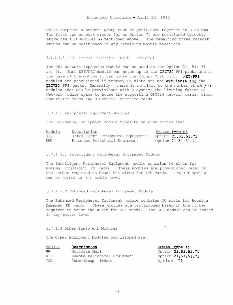
Autoquote Userguide - April 20, 1990
which comprise a network group must be positioned together in a column.The first two network groups for an Option 71 are positioned directlyabove the CPU modules as mentioned above. The remaining three networkgroups can be positioned in any remaining module positions.
3.7.1.1.5 PRI Network Expansion Module- (NET/PRI)
The PRI Network Expansion Module can be used on the Option 21, 51, 61and 71. Each NET/PRI module can house up to six QPC720 PRI packs and inthe case of the Option 21 can house the Floppy Disk Unit. NET/PRImodules are provisioned if primary CE slots are not apailable.for theQPC720 PRI packs. Generally, there is no limit to the number of NET/PRImodules that can be provisioned with a system; the limiting factor isNetwork module space to house the supporting QPC414 network cards, clockController cards and D-Channel Interface cards.
3.7.1.2 Peripheral Equipment Modules
The Peripheral Equipment module types to be provisioned are:
Module Description Svstem TvoetslIPE Intelligent Peripheral Equipment . Option 21,51,61,71EPE Enhanced Peripheral Equipment Option 21,51,61,71
3.7.1.2.1 Intelligent Peripheral Equipment Module
The Intelligent Peripheral Equipment module contains 16 slots forhousing Intelligent PE cards. These modules are provisioned based onthe number required to house the wired for IPE cards. The IPE modulecan be housed in any module level.
3.7.1.2.2 Enhanced Peripheral Equipment Module
The Enhanced Peripheral Equipment module contains 10 slots for housingEnhanced PE cards. These modules are provisioned based on the numberrequired to house the wired for EPE cards. The EPE module can be housedin any module level.
3.7.1.3 Other Equipment Modules --
The Other Equipment Modules provisioned are:
Module DeSCriDtiOn Svstem TvDe(s[MM Meridian Mail Option 21,51,61,71RPE Remote Peripheral Equipment Option 21,51,61,71IGM Inter-Group Module Option 71
45
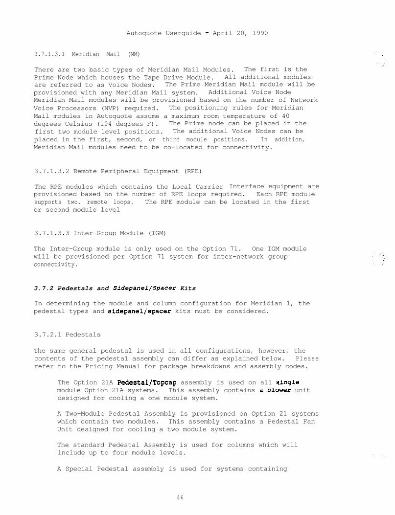
Autoquote Userguide - April 20, 1990
3.7.1.3.1 Meridian Mail (MM)
There are two basic types of Meridian Mail Modules. The first is thePrime Node which houses the Tape Drive Module. All additional modulesare referred to as Voice Nodes. The Prime Meridian Mail module will beprovisioned with any Meridian Mail system. Additional Voice NodeMeridian Mail modules will be provisioned based on the number of NetworkVoice Processors (NVP) required. The positioning rules for MeridianMail modules in Autoquote assume a maximum room temperature of 40degrees Celsius (104 degrees F). The Prime node can be placed in thefirst two module level positions. The additional Voice Nodes can beplaced in the first, second, or third module positions. In addition,Meridian Mail modules need to be co-located for connectivity.
3.7.1.3.2 Remote Peripheral Equipment (RPE)
The RPE modules which contains the Local Carrier Interface equipment areprovisioned based on the number of RPE loops required. Each RPE modulesupports two. remote loops. The RPE module can be located in the firstor second module level
3.7.1.3.3 Inter-Group Module (IGM)
The Inter-Group module is only used on the Option 71. One IGM modulewill be provisioned per Option 71 system for inter-network groupconnectivity.
3.7.2 Pedestals and Sidepanel/Spacer Kits
In determining the module and column configuration for Meridian 1, thepedestal types and sidepanel/spacer kits must be considered.
3.7.2.1 Pedestals
The same general pedestal is used in all configurations, however, thecontents of the pedestal assembly can differ as explained below. Pleaserefer to the Pricing Manual for package breakdowns and assembly codes.
The Option 21A Pedestal/Topcap assembly is used on all singlemodule Option 21A systems. This assembly contains a-blower unitdesigned for cooling a one module system.
A Two-Module Pedestal Assembly is provisioned on Option 21 systemswhich contain two modules. This assembly contains a Pedestal FanUnit designed for cooling a two module system.
The standard Pedestal Assembly is used for columns which willinclude up to four module levels.
A Special Pedestal assembly is used for systems containing
46

Autoquote Userguide - April 20, 1990
Meridian Mail. This assembly contains the same pedestal equipmentas in the standard Pedestal Assembly mentioned above, however amaximum of one of these assemblies can be ordered in systems whichcontain Meridian Mail.
The minimum required pedestal assemblies will be provisioned based onthe configuration quoted. However, Miscellaneous/Memory Input 11 can beused to override the pedestal provisioning assumptions. If Input 11 isset to 2, at least a two module pedestal assembly will be provisionedand if Input 11 is set to 4, a four module pedestal assembly will berequired.
3.7.2.2 Sidepanels/Spacer Kits
Sidepanels are provisioned for all module sides which are exposed.Spacer Kits are provisioned for every two adjoining modules. The numberof Sidepanels and Spacer Kits provisioned is based on the number ofmodules as well as the module placement within columns.
47
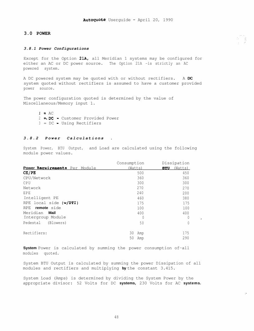
AutOquOte Userguide - April 20, 1990
3.0 POWER
3.8.1 Power Configurations
Except for the Option 21A, all Meridian 1 systems may be configured foreither an AC or DC power source. The Option 21A -is strictly an ACpowered system.
A DC powered system may be quoted with or without rectifiers. A DCsystem quoted without rectifiers is assumed to have a customer providedpower source.
The power configuration quoted is determined by the value ofMiscellaneous/Memory input 1.
1 = AC2 =.DC - Customer Provided Power3 = DC - Using Rectifiers
3.8.2 Power Calculations .
System Power, BTU Output, and Load are calculated using the followingmodule power values.
Power Reouirements Per ModuleCE/PECPU/NetworkCPUNetworkEPEIntelligent PERPE local side (w/DTI)RPE remote sideMeridian MailIntergroup ModulePedestal (Blowers)
Consumption(Watts)
500360300270240460175100400
050
DissipationBTU (Watts)
450360300270200380175100400
0 _0
Rectifiers: 30 Amp50 Amp
175290
System Power is calculated by summing the power consumption of-allmodules quoted.
System BTU Output is calculated by summing the power Dissipation of allmodules and rectifiers and multiplying by the constant 3.415.
System Load (Amps) is determined by dividing the System Power by theappropriate divisor: 52 Volts for DC systems, 230 Volts for AC systems.
. .:
48
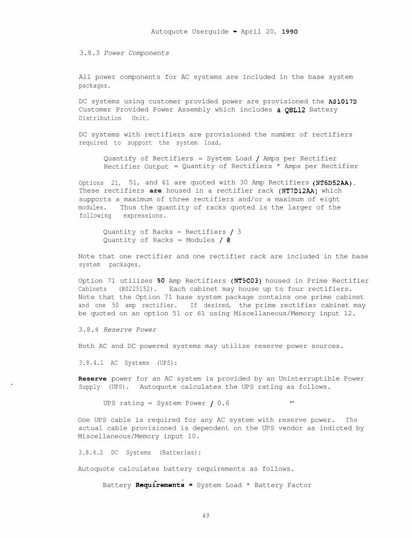
Autoquote Userguide - April 20, 1990
3.8.3 Power Components
All power components for AC systems are included in the base systempackages.
DC systems using customer provided power are provisioned the AS1017DCustomer Provided Power Assembly which includes a'QBL12 BatteryDistribution Unit.
DC systems with rectifiers are provisioned the number of rectifiersrequired to support the system load.
Quantify of Rectifiers = System Load / Amps per RectifierRectifier Output = Quantity of Rectifiers * Amps per Rectifier
Options 21, 51, and 61 are quoted with 30 Amp Rectifiers (NT6D52AA).These rectifiers are housed in a rectifier rack (NT7D12AA) whichsupports a maximum of three rectifiers and/or a maximum of eightmodules. Thus the quantity of racks quoted is the larger of thefollowing expressions.
Quantity of Racks = Rectifiers / 3Quantity of Racks = Modules / 8
Note that one rectifier and one rectifier rack are included in the basesystem packages.
Option 71 utilizes 50 Amp Rectifiers (NT5C03) housed in Prime RectifierCabinets (B0225152). Each cabinet may house up to four rectifiers.Note that the Option 71 base system package contains one prime cabinetand one 50 amp rectifier. If desired, the prime rectifier cabinet maybe quoted on an option 51 or 61 using Miscellaneous/Memory input 12.
3.8.4 Reserve Power
Both AC and DC powered systems may utilize reserve power sources.
3.8.4.1 AC Systems (UPS):
Reserve power for an AC system is provided by an Uninterruptible PowerSupply (UPS). Autoquote calculates the UPS rating as follows.
UPS rating = System Power / 0.6 _-
One UPS cable is required for any AC system with reserve power. Theactual cable provisioned is dependent on the UPS vendor as indicted byMiscellaneous/Memory input 10.
3.8.4.2 DC Systems (Batteries):
Autoquote calculates battery requirements as follows.
Battery Requcrements = System Load * Battery Factor
49
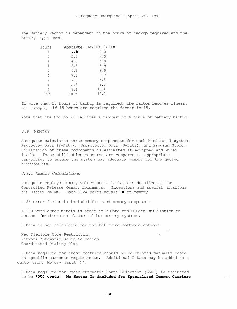
Autoquote Userguide - April 20, 1990
The Battery Factor is dependent on the hours of backup required and thebattery type used.
Hours Absolyte Lead-Calcium1 1.8 3.02 3.1 4.03 4.2 5.04 5.2 5.95 6.2 6.96 7.1 7.77 7.8 a.5a a.5 9.39 9.4 10.1
l-0 10.2 10.9
If more than 10 hours of backup is required, the factor becomes linear.For example, if 15 hours are required the factor is 15.
Note that the Option 71 requires a minimum of 4 hours of battery backup.
3.9 MEMORY
Autoquote calculates three memory components for each Meridian 1 system:Protected Data (P-Data), Unprotected Data (U-Data), and Program Store.Utilization of these components is estimated at equipped and wiredlevels. These utilization measures are compared to appropriatecapacities to ensure the system has adequate memory for the quotedfunctionality.
3.9.1 Memory Calculations
Autoquote employs memory values and calculations detailed in theControlled Release Memory documents. Exceptions and special notationsare listed below. Each 1024 words equals lk of memory.
A 5% error factor is included for each memory component.
A 900 word error margin is added to P-Data and U-Data utilization toaccount for the error factor of low memory systems.
P-Data is not calculated for the following software options:_-
New Flexible Code Restriction - _Network Automatic Route SelectionCoordinated Dialing Plan
P-Data required for these features should be calculated manually basedon specific customer requirements. Additional P-Data may be added to a
quote using Memory input 47.
P-Data required for Basic Automatic Route Selection (BARS) is estimatedto be 7000.words. No factor Is included for Specialized Common Carriers
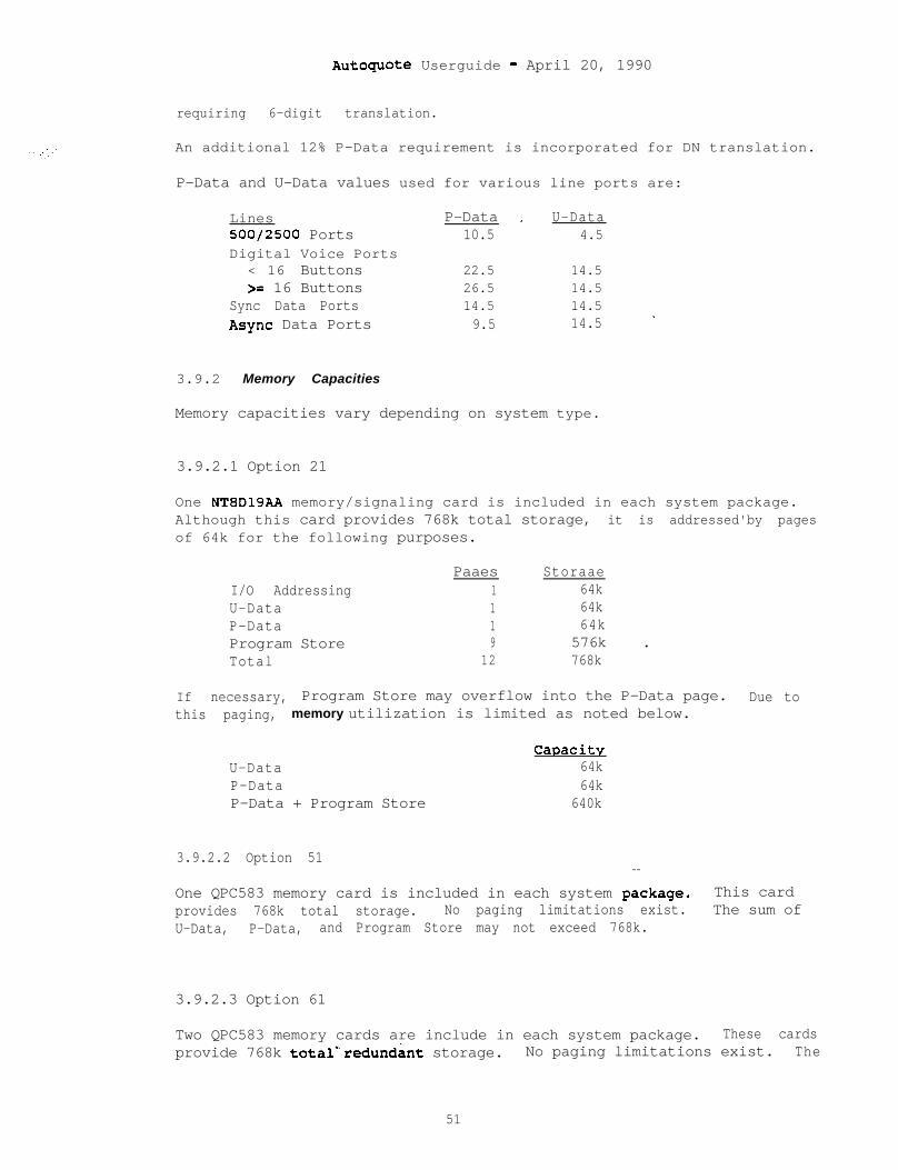
Autoguote Userguide - April 20, 1990
requiring 6-digit translation.
An additional 12% P-Data requirement is incorporated for DN translation.
P-Data and U-Data values used for various line ports are:
Lines P-Data _ U-Data500/2500 Ports 10.5 4.5Digital Voice Ports
< 16 Buttons 22.5 14.5>= 16 Buttons 26.5 14.5
Sync Data Ports 14.5 14.5_Async Data Ports 9.5 14.5
3.9.2 Memory Capacities
Memory capacities vary depending on system type.
3.9.2.1 Option 21
One NT8D19AA memory/signaling card is included in each system package.Although this card provides 768k total storage, it is addressed'by pagesof 64k for the following purposes.
I/O AddressingU-DataP-DataProgram StoreTotal
Paaes Storaae1 64k1 64k1 64k9 576k .
12 768k
If necessary, Program Store may overflow into the P-Data page. Due tothis paging, memory utilization is limited as noted below.
U-DataP-DataP-Data + Program Store
Caoacitv64k64k
640k
3.9.2.2 Option 51--
One QPC583 memory card is included in each system .package. This cardprovides 768k total storage. No paging limitations exist. The sum ofU-Data, P-Data, and Program Store may not exceed 768k.
3.9.2.3 Option 61
Two QPC583 memory cards are include in each system package. These cardsprovide 768k total*'redund&t storage. No paging limitations exist. The
51
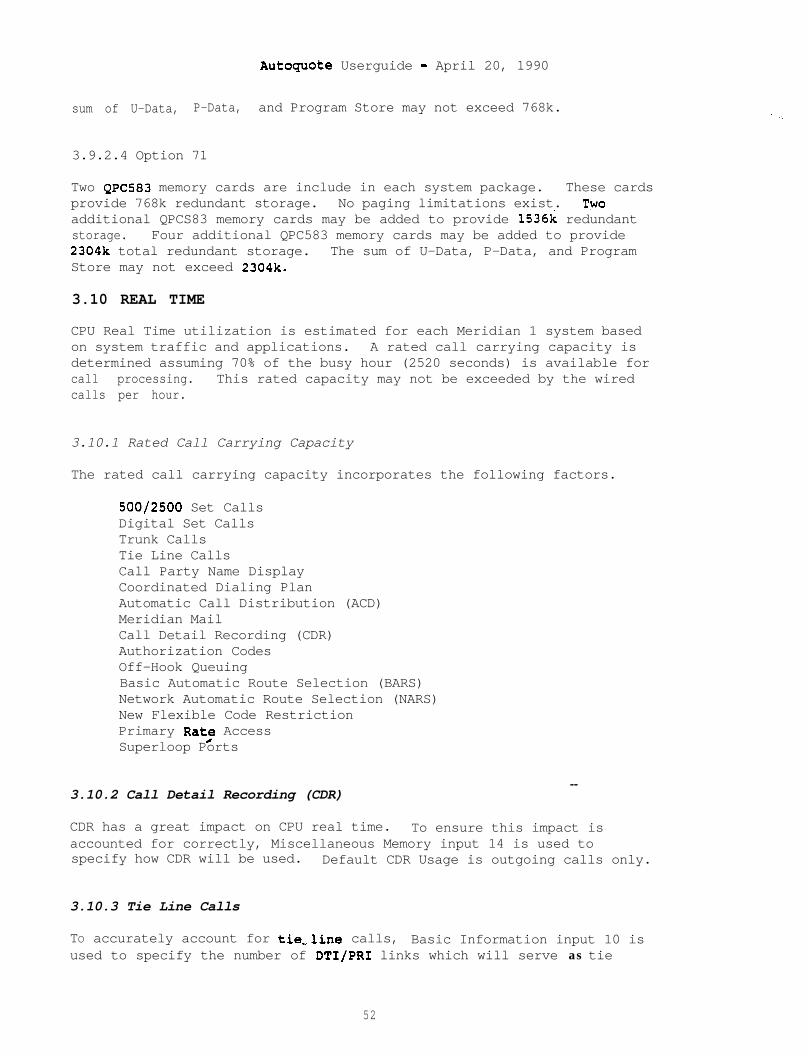
Autoquote Userguide - April 20, 1990
sum of U-Data, P-Data, and Program Store may not exceed 768k. . - - .
3.9.2.4 Option 71
Two QPC583 memory cards are include in each system package. These cardsprovide 768k redundant storage. No paging limitations exist. Twoadditional QPCS83 memory cards may be added to provide 1536k redundantstorage. Four additional QPC583 memory cards may be added to provide2304k total redundant storage. The sum of U-Data, P-Data, and ProgramStore may not exceed 2304k.
3.10 REAL TIME
CPU Real Time utilization is estimated for each Meridian 1 system basedon system traffic and applications. A rated call carrying capacity isdetermined assuming 70% of the busy hour (2520 seconds) is available forcall processing. This rated capacity may not be exceeded by the wiredcalls per hour.
3.10.1 Rated Call Carrying Capacity
The rated call carrying capacity incorporates the following factors.
500/2500 Set CallsDigital Set CallsTrunk CallsTie Line CallsCall Party Name DisplayCoordinated Dialing PlanAutomatic Call Distribution (ACD)Meridian MailCall Detail Recording (CDR)Authorization CodesOff-Hook QueuingBasic Automatic Route Selection (BARS)Network Automatic Route Selection (NARS)New Flexible Code RestrictionPrimary Rat/e AccessSuperloop Ports
3.10.2 Call Detail Recording (CDR)--
CDR has a great impact on CPU real time. To ensure this impact isaccounted for correctly, Miscellaneous Memory input 14 is used tospecify how CDR will be used. Default CDR Usage is outgoing calls only.
3.10.3 Tie Line Calls
TO accurately account for tie,,line calls, Basic Information input 10 isused to specify the number of DTI/PRI links which will serve as tie
52

Autoquote Userguide - April 20, 1990
lines. The default is zero.
3.10.4 Calls Per Hour
The number of calls per hour is calculated as follows.
P * 100 * 0.5 / H
where P = Total traffic in CCSH = Average Holding Time
The default Average Holding Time is 180 seconds, but m_ay this be alteredusing Miscellaneous/Memory input 23.
53
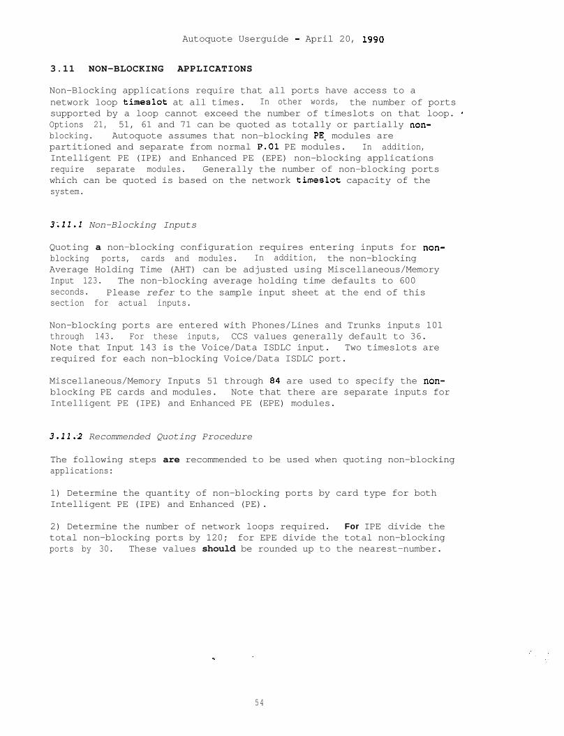
Autoquote Userguide - April 20, 1990
3.11 NON-BLOCKING APPLICATIONS
Non-Blocking applications require that all ports have access to anetwork loop timeslot at all times. In other words, the number of portssupported by a loop cannot exceed the number of timeslots on that loop. *Options 21, 51, 61 and 71 can be quoted as totally or partially non-blocking. Autoquote assumes that non-blocking PEW modules arepartitioned and separate from normal P.01 PE modules. In addition,Intelligent PE (IPE) and Enhanced PE (EPE) non-blocking applicationsrequire separate modules. Generally the number of non-blocking portswhich can be quoted is based on the network timeslot capacity of thesystem.
3;ll.l Non-Blocking Inputs
Quoting a non-blocking configuration requires entering inputs for non-blocking ports, cards and modules. In addition, the non-blockingAverage Holding Time (AHT) can be adjusted using Miscellaneous/MemoryInput 123. The non-blocking average holding time defaults to 600seconds. Please refer to the sample input sheet at the end of thissection for actual inputs.
Non-blocking ports are entered with Phones/Lines and Trunks inputs 101through 143. For these inputs, CCS values generally default to 36.Note that Input 143 is the Voice/Data ISDLC input. Two timeslots arerequired for each non-blocking Voice/Data ISDLC port.
Miscellaneous/Memory Inputs 51 through 84 are used to specify the non-blocking PE cards and modules. Note that there are separate inputs forIntelligent PE (IPE) and Enhanced PE (EPE) modules.
3.11:2 Recommended Quoting Procedure
The following steps are recommended to be used when quoting non-blockingapplications:
1) Determine the quantity of non-blocking ports by card type for bothIntelligent PE (IPE) and Enhanced (PE).
2) Determine the number of network loops required. For IPE divide thetotal non-blocking ports by 120; for EPE divide the total non-blockingports by 30. These values should be rounded up to the nearest-number.
54

Autoquote Userguide - April 20, 1990
3) Determine the number of PE cards and shelves required by manuallymapping out each loop with the type of ports to be assigned to thatloop. PE card calculation should include any Digitone Receiverrequirements. (This drawing can be sent in with the order to assure thesystem is built as the non-blocking system quoted) Note that analogline cards require Ringing Generators. Therefore, by noting thequantity of IPE and EPE shelves which contain analog line cards, thisvalue can be entered into Miscellaneous Inputs 83. and'84. Also, foreach Intelligent PE module which require more than 2 Superloops, aController-4 Card will have to be entered in Miscellaneous/Memory Input82.
Total all non-blocking IPE and EPE shelves and cards from step 3..
Enter non-blocking ports in the appropriate non-blocking Phones Linesand Trunks inputs and enter the results of step 4 into the non-blockingMiscellaneous Memory Input section.
55
Autoquote Userguide - April 20, 1590
3.12 MERIDIAN MAIL
Meridian Mail may be quoted with Options 21, 51, 61 and 71. MeridianMail is quoted by either using Miscellaneous/Memory Input 150 for theMeridian Mail Modular system or by.Aux Loading a Meridian Mail X Cabinetonto an existing quote.
3.12.1 Meridian Mail Modular
The Meridian Mail Modular system can be quoted by entering the desiredPorts, Hours and Users in Miscellaneous Memory Input 150. When thisinput is used, the complete Meridian Mail hardware and softwarepackaging will be included in the quote as well as any supportingequipment such as network loops, ESDI card slots, pedestals and power.This section addresses the configuration rules for the Meridian Mailhardware and software. For information on switch impact of MeridianMail, please refer to previous portions of this Engineering/Provisioningsection.
Meridian Mail Hardware is based upon the amount of Voice Processor Portsand Hours of storage requested. Meridian Mail Modular configurationsconsist of a combination of a Base Package, additional Network VoiceProcessor Cards (NVP), Expansion Storage Software and ExpansionAssemblies. Each NVP card contains four Voice Processor ports. VoiceStorage hours is determined by the amount of disk space available.Configurations include different combinations of 155MB, 300MB and 600MBdisks. The following chart shows the relationship of theseconfigurations. Note that the Ports column shows the capacities withadditional NVP cards added.
With With WithBase Package Expanded Storage Exp. Assembly BothPORTS HOURS PORTS HOURS PORTS HOURS PORTS HOURS
4 5 -- -- -- -- 12 54 11 12 24 20 26 20 544 36 12 54 20 a 4 20 114
24 45 36 90 48 60 l 48 12024 120 36 la0 48 la0 48 240
The corresponding order codes for these configurations are as follows:
Base Packacre Base Software ExDanded Software EXD. Assembiv
SY7000 SW7001 -- --SY7001 SW7000 SW7003 AS7000SY7002 SW7000 SW7003 AS7001SY7003 SW7000 SW7003 AS7004SY7004 SW7000 SW7003 AS7005
56

Autoquote Userguide - April 20, 1990
As shown in the above chart, every Meridian Mail Modular system comeswith a Base Software Package. For configurations of not more than fivehours of storage, the SW7001 5 Hour Software base package is included.All other configurations require the SW7000 Meridian Mail Base Software.Expansion Storage Software (SW7003) is provisioned to increase voicestorage capacity if required.
The remaining Meridian Mail applications are selected usingMiscellaneous/Memory Inputs 151-156. As most of these inputs aresoftware applications, enter a 1 to select the option. In the case ofVoice Menus, any positive number input will provision Voice Menussoftware, however, by entering the number of Voice Menu Calls expectedduring the busy hour, this input can also be used in determining the CPUReal Time impact. .
Input 155 is Meridian Mail Networking Ports. By entering the number ofMeridian Mail Networking Ports required in this input, the Meridian Mail
. Networking Software and appropriate hardware will be provisioned. Thehardware for this application includes a Networking Hardware Package anda Modem Package. The Networking Hardware Package includes one 4-portRS232 board and 2 modems. The Modem package is provisioned if more thantwo total networking ports are required and includes 2 additionalmodems.
3.12.2 Meridian Mail X Cabinet
The Meridian Mail X Cabinet can be quoted in conjunction with a Meridian1 system by creating a separate Meridian Mail quote and Aux Loading itonto the Meridian 1. Creating the Meridian Mail X quote is accomplishedusing the Autoquote Model "MM". Please refer to the Meridian MailProduct Chapter for information on quote the X Cabinet.
57
Autoquote Userguide - April 20, 1550
3.13 REMOTE PERIPHERAL EQUIPMENT (RPE)
Remote Peripheral Equipment (RPE) may be quoted with any Meridian 1Option 21, 51, 61 or 71. The quoting process is identical to a normalMeridian 1 quotation with the addition of the AUX Loading function asdescribed in Section 4 of this User Guide.
As there is no Common Equipment (CE) in an RPE system, the SoftwareInput Class does not apply. Therefore the only inputs necessary on anRPE system are:
- Phones Lines and Trunks- Miscellaneous/Memory- Basic Information
To set up an RPE quote, use either the RPE or RPEC Autoquote Models.(These models do not have an associated release number; enter a RETURNat the Release prompt.) The RPE model is used to.quote the Meridian 1modular packaged RPE while the RPEC model is used to quote the QCA74style RPE cabinet.
Although networks, digitone receivers and memory are not quoted for anRPE system, they are calculated so they can be accomodated at the mainsite when Aux Loading is performed.
.,;.’
Please reference Section 5, Aux Loading, page 77 of this User Guide forinformation on how to Aux Load an RPE system. RPE software must beselected on the Main circuit switch quote before Auxiliary Loading.
58
Autoquote Userguide - April 20, 1990
4 . REPORTS
This section contains samples of mOSt reports available on Meridian SL-1quotation models. An explanation of each report is also included.
Report--------------------------Header ReportPrice SummaryEngineering SummaryEquipment SummaryInput ListingAuxiliary Quote SummaryEquipment ListUnused Capacity Summary
#
99991456792 0
A sample of report 15 Discount Summary and Report 11 Auxiliary PriceSummary will not appear in the User guide. These reports providediscounting information which may vary for different Autoquote users.Report 3 is available and is the same as Report 9 without pricinginformation.
Please note that many of the engineering and configuration reportsdisplay "Equipped" and "Wired" values for hardware. The Meridian SL-1Autoquote models calculate equipped and wired configurations in the samerun. Details on these two values are often needed when the customerrequires a certain amount of growth capacity engineered into the system.For all line, trunk and data pcrts, the user can input both the equippedand wired quantities desired. The SL-1 Autoquote will then configure asystem where all hardware needed for the equipped configuration isincluded and the only things lacking for the wired configuration are PEcards. All other hardware (CE equipment, power equipment, memory,network capacity, cabinets and shelves) is quoted to support the wiredconfiguration.
The mechanics of using Autoquote are not included in this productchapter. Refer to the Introduction and chapter for detailed informationon how to use the Autoquote system.
59

Autoquote Userguide - April 20, 1990
4.1 Header - Report 9999
The "Report Header" is produced each time that Report is selected fromthe service menu or it can be reproduced by requesting report number9999. This report displays general information that is input when a NewQuote is created or that has been entered by selecting GeneralInformation at the Service Menu.
60
Autoquote Userguide - April 20, 1990
********************RR*****************
NORTHERN TELECOM MBS QUOTATION SYSTEM'RUN DATE:'CREATION DATE
04/04/9004/04/90
QUOTATION FOR:
3AUTOQUOTE'MERIDIAN 1 SYSTEM OPTION 21 'AC6X11 RELEASE 15
QUOTED BY ('AQM ):8AUTOQUOTE ADMIN 'ORDER DATE: 11/11/99 _
QUOTATION. NUMBER: 00003556USER GUIDE
lo* THIS CONFIGURATION IS BASED UPON NT1 ENGINEERING RULES INEFFECT AS OF THIS DATE BUT PRIOR TO DISTRIBUTORS SUBMISSION OFAN ORDER. ALTHOUGH ENGINEERING RULES MAY CHANGE IN THE FUTURE, NT1 WILLHONOR THE QUOTED FUNCTIONALITY FOR SIXTY DAYS FROM THIS DATE. PRICING ISGOVERNED SOLELY BY THE NT1 CPE DISTRIBUTORSHIP AGREEMENT BETWEEN EACHDISTRIBUTOR AND NTI, AND THE MERIDIAN BUSINESS SYSTEMS PRICING MANUAL INEFFECT ON THE DATE NT1 ACCEPTS THE DISTRIBUTORS ORDER.
THE PRICE QUOTED BY THE AUTOQUOTE SYSTEM APPLIES ONLY TO THE ITEMS OFEQUIPMENT AND SOFTWARE LISTED 'IN THE EQUIPMENT BREAKOUT (IE. REPORT 3).THESE ITEMS ARE BASED SOLELY ON THE INPUTS. THE ACTUAL SYSTEM PRICEDEPENDS ON PARTICULAR APPLICATIONS AND FINALIZED SYSTEM ENGINEERINGWHICH MAY REQUIRE MANUAL ADDITIONS OR DELETIONS TO THIS QUOTE.
'RUN DATE is the date on which the quotation was run (MM/DD/YY).
2CREATION DATE is the date on which the quote was created as a newquote or copied to a new quote number.
3QUOTATION FOR is the END USER COMPANY NAME entered as part of theinformation entered when setting up a new quote or changed withinGeneral Information.
4 This is the system type being quoted. The system type is determinedby the response to MODEL/GENERIC entered as part of a new quote orchanged quote using the MODEL command --5Either AC or DC depending on the system power option that was selectedunder miscellaneous inputs.
6The Software Release is input at the RELEASE prompt when creating anew quote or changing an existing quote using the Model command
7Sales Channel Acronym, entered as part of the system sign onprocedure: HELLO (Location ID),(Sales Channel).NTII
8 Salesperson enter%d when creating a new quote or changing an existing
61

Autoquote Userguide - April 20, 1990
quote using the General Information command.
9Order Date is the anticipated order date input when creating a newquote or changed quote using the General Information command.
10 Caveats, Disclaimers, and Notes
62
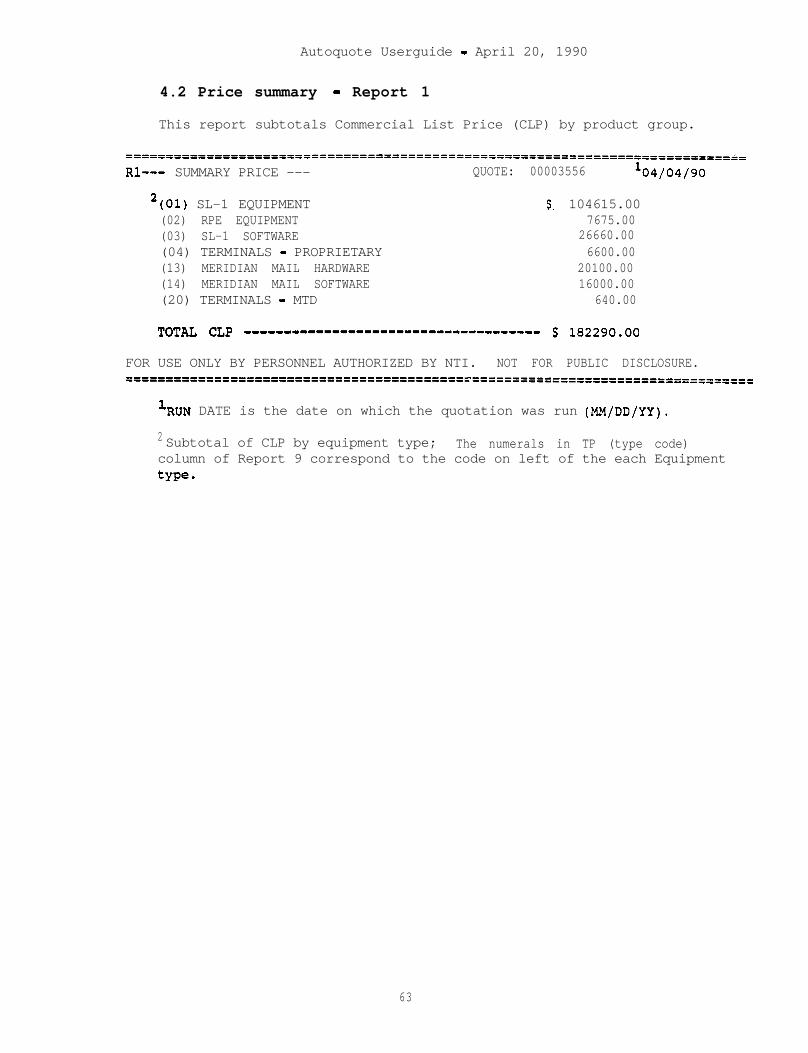
Autoquote Userguide - April 20, 1990
4.2 Price summary - Report 1
This report subtotals Commercial List Price (CLP) by product group.
=====---------------============================================------=====~=
Rl--- SUMMARY PRICE --- QUOTE: 00003556 lo4/04/90
2(01) SL-1 EQUIPMENT $. 104615.00(02) RPE EQUIPMENT 7675.00(03) SL-1 SOFTWARE 26660.00(04) TERMINALS - PROPRIETARY 6600.00(13) MERIDIAN MAIL HARDWARE 20100.00(14) MERIDIAN MAIL SOFTWARE 16000.00(20) TERMINALS - MTD 640.00
TOTa CLP ------------------------------------- $ 182290.00
FOR USE ONLY BY PERSONNEL AUTHORIZED BY NTI. NOT FOR PUBLIC DISCLOSURE.==============================================================================
'RUN DATE is the date on which the quotation was run (MM/DD/YY).
2 Subtotal of CLP by equipment type; The numerals in TP (type code)column of Report 9 correspond to the code on left of the each Equipmenttype.
63
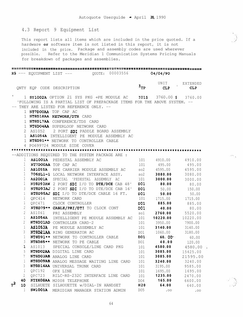
Autoquote Userguide - April 20, 1990
4.3 Report 9 Equipment List
This report lists all items which are included in the price quoted. If ahardware or software item is not listed in this report, it is notincluded in the price. Package and assembly codes are used whereverpossible. Refer to the Meridian 1 Communication Systems Pricing Manualsfor breakdown of packages and assemblies.
======================f=========================================================R9 --- EQUIPMENT LIST --- QUOTE: 00003556 04/04/90
QNTY EQP CODE DESCRIPTIONUNIT EXTENDED
3TP CLP _ CLP
* 1 SY1002A OPTION 21 SYS PKG +PE MODULE AC 101s 3760.00 $ 3760.00'FOLLOWING IS A PARTIAL LIST OF PREPACKAGE ITEMS FOR THE ABOVE SYSTEM. --
-- THEY ARE LISTED FOR REFERENCE ONLY. --1 NT7DOOAA TOP CAP AC1 NTSDlSAA NETWORK/DTR CARD1 NTSD17AA CONFERENCE/TDS CARD1 NTSD04A.A SUPERLOOP NETWORK CARD2 AS1052 2 PORT SD1 PADDLE BOARD ASSEMBLY1 AS1054A INTELLIGENT PE MODULE ASSEMBLY AC1 NTSD91** NETWORK TO CONTROLLER CABLE4 PO699724 MODULE SIDE COVER
******************************************************************************--ADDITIONS REQUIRED TO THE SYSTEM PACKAGE ARE :
1111113111221213131571312
T2 ;:1
ASlOOlANT7DOOAAASl055A706SLl-1AS2001ANTSD93AWNTSD93AJNTSD95AJQPC414QPC471NTSD79**AS1061AS1054ANTSDOlADAS1053ANTSD21AANTSD91**NTSD85**AS1013NTSD02AANTSD03ABNTSD09ABNTSD14AAQPC192QPC723NTZXOSAASILHUETESWlOOlA
PEDESTAL ASSEMBLY ACTOP CAP ACRPE CARRIER MODULE ASSEMBLY ACLOCAL NETWORK INTERFACE ASSY.SPECIAL 'PEDESTAL ASSEMBLY AC2 PORT SD1 I/O TO DTE/DCE CAB 48'2 PORT SD1 I/O TO DTE/DCE CAB 16'SD1 I/O TO DTE/DCE CABLE 16 FT.NETWORK CARDCLOCK CONTROLLERCABLE/PRI/DTI TO CLOCK CONTPRI ASSEMBLYINTELLIGENT PE MODULE ASSEMBLY ACCONTROLLER CARD-2PE MODULE ASSEMBLY ACRING GENERATOR ACNETWORK TO CONTROLLER CABLENETWORK TO PE CABLESPECIAL CONSOLE/LINE CARD PKGDIGITAL LINE CARDANALOG LINE CARDANALOG MESSAGE WAITING LINE CARDUNIVERSAL TRUNK CARDOPX LINERILC-RS-232C INTERFACE LINE CARDM2008 TELEPHONESILHOUETTE w/DIAL-IN HANDSETMERIDIAN MANAGER STATION ADMIN
64
101 4910.00 4910.00101 495.00 495.00so2 4595.00 4595.00so2 3 0 8 0 . 0 0 3080.00101 3 0 0 0 . 0 0 3000.00DO1 8 0 . 0 0 80.00DO1 50.00 150.00DO1 5 0 . 0 0 50.00101 1715.00 1715.00DO1 8 8 5 . 0 0 885.00DO1 4 0 . 0 0 80.00so1 2 7 6 0 . 0 0 5520.00101 1 0 2 2 0 . 0 0 10220.00101 3950.00 7900.00101 3 1 4 0 . 0 0 3140.00DO1 1060.00 3180.00DO1 6 0 . OO- 60.00DO1 4 0 . 0 0 120.00101 4 5 8 0 . 0 0 4580.00 .101 3 0 8 5 . 0 0 15425.00101 3 0 8 5 . 0 0 21595.00101 3 2 4 0 . 0 0 3240.00101 3195.00 9585.00101 1695.00 1695.00101 1 2 3 5 . 0 0 2470.00DO4 1 6 5 . 0 0 6600.00H 2 0 6 4 . 0 0 640.00DO5 .oo .oo
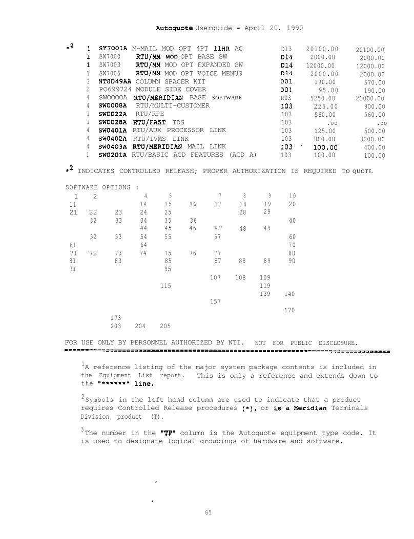
AutOquOte Userguide - April 20, 1990
*2 11113244114441
SY7001A M-MAIL MOD OPT 4PT 1lHR ACSW7000 RTU/MM MOD OPT BASE SWSW7003 RTU/MM MOD OPT EXPANDED SWSW7005 RTlJ/MM MOD OPT VOICE MENUSNT8D49AA COLUMN SPACER KITPO699724 MODULE SIDE COVERSWOOOOA RTUIMERIDIAN BASE SOFTWARE
SWOOOSA RTU/MULTI-CUSTOMERSW0022A RTU/RPESW0028A RTU/FAST TDSSW0401A RTU/AUX PROCESSOR LINKSW0402A RTU/IVMS LINKSW0403A RTUjMERIDIAN MAIL LINKSW0201A RTU/BASIC ACD FEATURES (ACD A)
D13 20100.00 20100.00D14 2000.00 2000.00D14 12000.00 12000.00D14 2000.00 2000.00DO1 190.00 570.00DO1 95.00 190.00R03 5250.00 21000.00I-03 225.00 900.00103 560.00 560.00103 .oo .oo103 125.00 500.00103 800.00 3200.00IO3 _ lOO.OC 400.00103 100.00 100.00
*2 INDICATES CONTROLLED RELEASE; PROPER AUTHORIZATION IS REQUIRED TO QUOTE.
SOFTWARE OPTIONS :1 2 4 5 7 8 9 10
11 14 15 16 17 18 19 2021 22 23 24 25 28 29
32 33 34 35 36 4044 45 46 47' 48 49
52 53 54 55 57 6061 64 7071 72 73 74 75 76 77 8081 83 85 87 88 89 9091 95
107 108 109115 119
139 140157
170173203 204 205
FOR USE ONLY BY PERSONNEL AUTHORIZED BY NTI. NOT FOR PUBLIC DISCLOSURE.====================0==============P================================================
1A reference listing of the major system package contents is included inthe Equipment List report. This is only a reference and extends down tothe "*******I line.
2Symbols in the left hand column are used to indicate that a productrequires Controlled Release procedures (*), or is %Meridian TerminalsDivision product (T).
3The number in the "TP" column is the Autoquote equipment type code. Itis used to designate logical groupings of hardware and software.
c
.
65

Autoquote Userguide - April 20, 1990
4.4 Report 4 Engineering Summary
The Engineering Summary Report displays engineering information onmemory, power, system traffic and processor real time. For details oncalculating these items, please see Section 3, Engineering\Provisioning,page 27.
--
*.
66
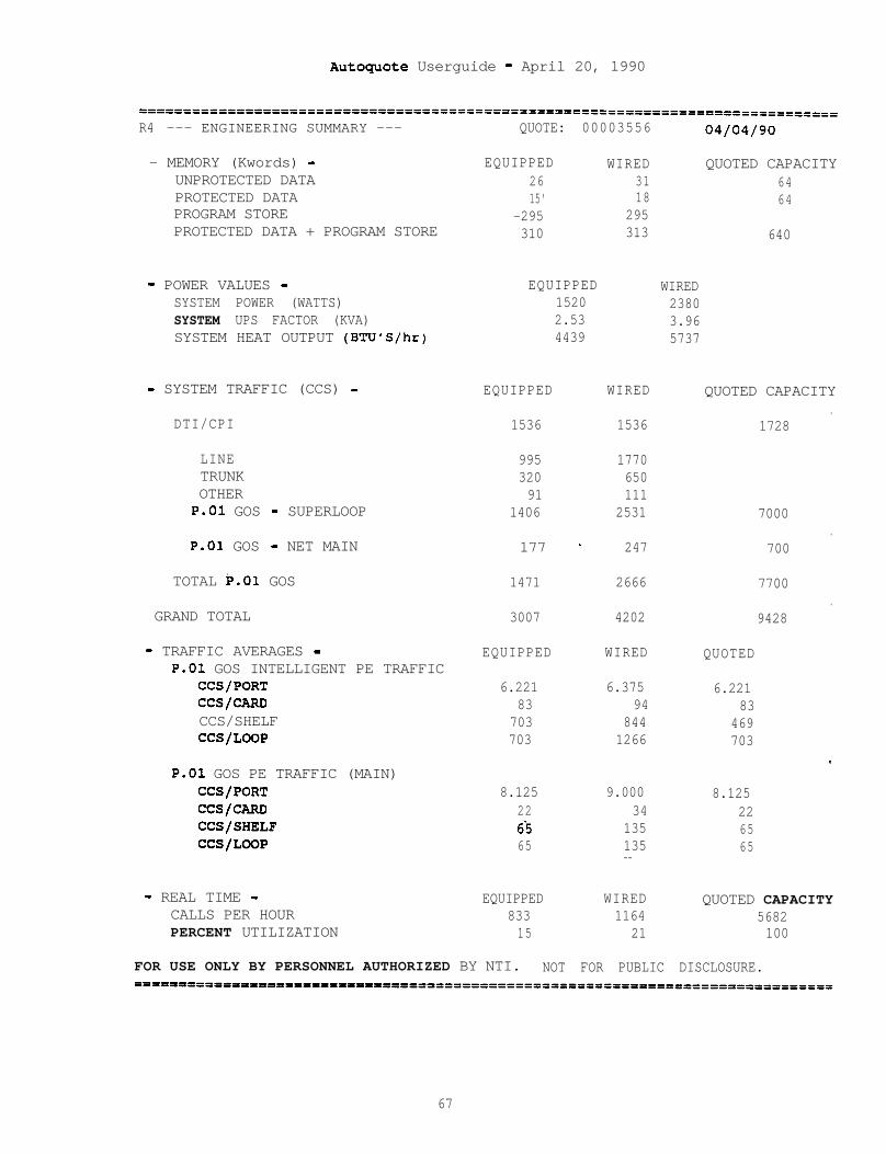
Autoguote Userguide - April 20, 1990
R4 --- ENGINEERING SUMMARY ---
- MEMORY (Kwords) -UNPROTECTED DATAPROTECTED DATAPROGRAM STOREPROTECTED DATA + PROGRAM STORE
QUOTE: 00003556
EQUIPPED2615'
-295310
WIRED3118
295313
QUOTED CAPACITY6464
640
- POWER VALUES - EQUIPPED WIREDSYSTEM POWER (WATTS) 1520 2380SYSTEM UPS FACTOR (KVA) 2.53 3.96SYSTEM HEAT OUTPUT (BTU'S/hr) 4439 5737
- SYSTEM TRAFFIC (CCS) -
DTI/CPI
EQUIPPED WIRED
1536 1536
QUOTED CAPACITY.
1728
LINETRUNKOTHER
P.01 GOS - SUPERLOOP
P.01 GOS - NET MAIN
TOTAL b.01 GOS
995 1770320 65091 111
1406 2531
177 - 247
7000.
700
1471 2666
GRAND TOTAL 3007 4202
7700.
9428
- TRAFFIC AVERAGES -P.01 GOS INTELLIGENT PE TRAFFIC
CCS/PORTccs/cARDCCS/SHELFCCS/LOOP
EQUIPPED WIRED QUOTED
6.221 6.375 6.22183 94 83
703 844 469703 1266 703
P.01 GOS PE TRAFFIC (MAIN)CCS/PORTccs/cARDCCS/SHELFCCS/LOOP
8.125226-565
9.00034
135135--
8.125226565
- REAL TIME - EQUIPPED WIRED QUOTED CAPACITYCALLS PER HOUR 833 1164 5682PERCENT UTILIZATION 15 21 100
FOR USE ONLY BY PERSONNEL AUTHORIZED BY NTI. NOT FOR PUBLIC DISCLOSURE.
67
Autoquote Userguide - April 20, 1990
4.4.1 Memory
For questions regarding Memory values refer to Section 3.9, Memory, page50.
UNPROTECTED DATA, PROTECTED DATA and PROGRAM STORE memory values aredisplayed for the Equipped and Wired configurations. System'capacitiesare also displayed when appropriate; e.g. for PROGRAM STORE + P-DATAand TOTAL MEMORY. All values are in words of memory.
4.4.2 Power
For questions regarding power values refer to Power, page 47.
SYSTEM POWER is the sum of the modules power in Watts.
SYSTEM UPS (Uninterruptable Power Supply) FACTOR is (System Power) /(.6). for AC Systems.
SYSTEM HEAT OUTPUT is the sum of the modules and rectifiers heat output.
HOURS BATTERY BACXUP is the number of hours of battery backup requested(For DC Systems).
BATTERY REQUIREMENTS (AMP HOURS) is the amount of amp-hours thebatteries must be rated to support the specified amount of backupDC Systems).
(For
RECHARGE TIME is the number of hours required to recharge the quotedbatteries after they have been completely discharged (For DC Systems).
4.4.3 System Traffic
For questions regarding traffic values refer to Network LoopEngineering, page 36.
Total system traffic is broken into NON-BLOCKING, PRI/DTI/CPI, and P.01GOS quantities for* both the Main and RPE sites. OTHER CCS representsConsole, Digitone Receiver (main location) and Meridian Mail trafficcalculated for the system.
--
4.4.4 Real Time
For questions regarding real time values refer to Section 3.10, RealTime, page 52.
The values described in this section of Report 4 deal with theprocessing time of the CPU. When applicable, equipped and wired valuesare given. *,
68

Autoguote Userguide - April 20, 1990
The equipped and wired CALLS PER HOUR is a measure of the number ofcalls made per hour based on traffic and average holding time. The CALLPER HOUR quoted capacity is a rated capacity based on system featureutilization. Real time intensive features (CDR, ACD, Meridian Mail)decrease this CALL PER HOUR quoted capacity since the fea'tureutilization reduces the time available for'call processing.
PERCENT UTILIZATION is Simply a percentage measure of the CALLS PER HOUR
equipped or wired versus the CALLS PER HOUR quoted capacity. ThePERCENT UTILIZATION quoted capacity is always 100.
69
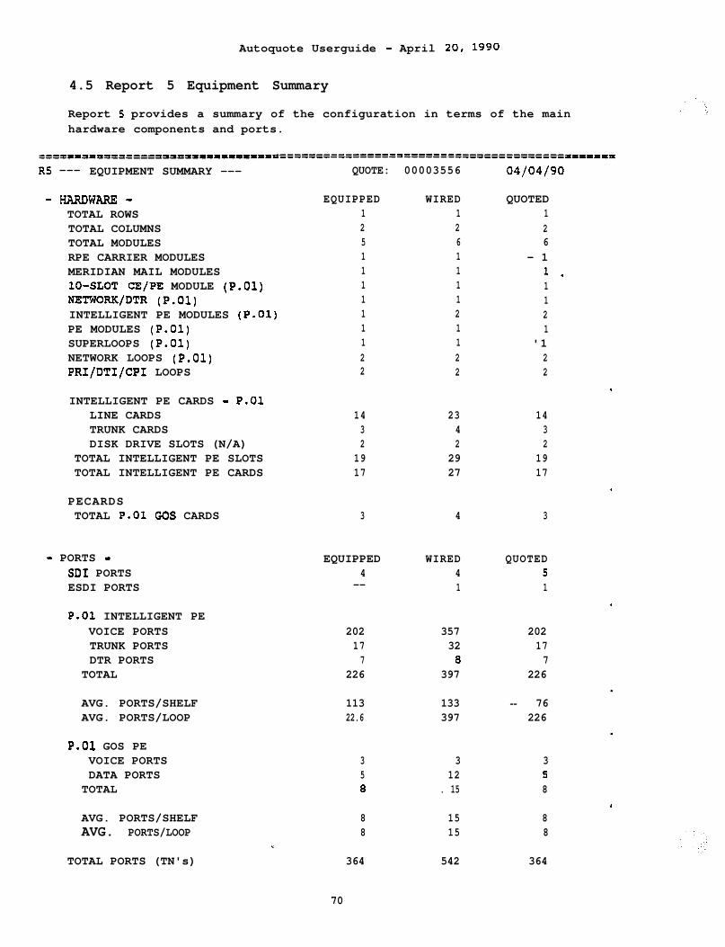
Autoquote Userguide - April 20, 1990
4.5 Report 5 Equipment Summary
Report 5 provides a summary of the configuration in terms of the mainhardware components and ports.
RS --- EQUIPMENT SUMMARY ---
-HARDwARE-TOTAL ROWSTOTAL COLUMNSTOTAL MODULESRPE CARRIER MODULESMERIDIAN MAIL MODULESlo-SLOT CE/PE MODULE (P.01)NETWORK/DTR (P.01)INTELLIGENT PE MODULES (P.01)PE MODULES (P.01)SUPERLOOPS (P.01)NETWORK LOOPS (P.01)PRI/DTI/CPI LOOPS
QUOTE: 00003556
EQUIPPED WIRED1 12 25 61 11 11 11 11 21 11 12 22 2
QUOTED126
- 11 -1121
'122
INTELLIGENT PE CARDS - P.01LINE CARDSTRUNK CARDSDISK DRIVE SLOTS (N/A)
TOTAL INTELLIGENT PE SLOTSTOTAL INTELLIGENT PE CARDS
14 23 143 4 32 2 2
19 29 1917 27 17
PECARDSTOTAL P.01 GCS CARDS 3 4 3
- PORTS - EQUIPPED WIRED QUOTEDSD1 PORTS 4 4 5ESDI PORTS -- 1 1
P.01 INTELLIGENT PEVOICE PORTSTRUNK PORTSDTR PORTS
TOTAL
202 357 20217 32 177 0 7
226 397 226
AVG. PORTS/SHELFAVG. PORTS/LOOP
113 133 -- 7622.6 397 226
P.01 GOS PEVOICE PORTSDATA PORTS
TOTAL
3 3 35 12 50 . 15 8
AVG. PORTS/SHELFAVG. PORTS/LOOP
*.TOTAL PORTS (TN's)
8 15 88 15 8
364 542 364
70
.
.
.
Autoguote Userguide - April 20, 1990
4.5.1 Hardware
The information in the Hardware section of this report represents thenumber of key of an item equipped, wired and quoted. The quoted levelshould correspond to the equipped levei for calculations of PeripheralEquipment (EPE & IPE) cards, ports , and TN's. For all othercalculations the quoted level should correspond to the wired level.
For details on calculating these items, see Section 3, Engineering \Provisioning, page 27.
4.5.2 Ports
SDI, D-Channel Interface, and ESDI (Enhanced SD1 for Meridian Mail)ports are listed for reference.
Ports average are calculated at module and network loop level for P.01Grade of Service (GOS) and Non-blocking configurations.
.
71
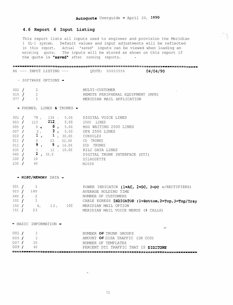
Autoquote Userguide - April 20, 1990
4.6 Report 6 Input Listing
This report lists all inputs used to engineer and provision the Meridian1 SL-1 system. Default values and input adjustments will be reflectedin this report. Actual "saved" inputs can be viewed when loading anexisting quote. The inputs will be stored as shown on this report ifthe quote is "saved" after running reports. -
R6 --- INPUT LISTING --- QUOTE: 00003556 04/04/90
- SOFTWARE OPTIONS -
002 / 1015 / 1077 / 1
- PHONES, LINES & TRUNKS -
001 / 78 , 134 , 5.00003 / 113 , 212. , 5.00005 / 8 v 8 t 5.00007 / 3 , 3, 5.00010 / 1 I 1 t 30.00011 / 8 , 23 , 22.00012 / 9 I 9 I 16.00035 / 5 , 12 , 10.00040 / 2 I 32.0100 / 10230 / 40
- MISC/MEMORY DATA -
001 / 1023 / 180040 / 2102 / 1150 / 4, 12, 100151 / 23
- BASIC INFORMATION -
001 / 2005 / 2007 / 25009 / 40
MULTI-CUSTOMER .REMOTE PERIPHERAL EQUIPMENT (RPE)MERIDIAN MAIL APPLICATION
DIGITAL VOICE LINES2500 LINESMSG WAITING 2500 LINESOPX 2500 LINESCONSOLESCO TRUNKSDID TRUNKSRILC DATA LINESDIGITAL TRUNK INTERFACE (DTI)SILHOUETTEM2008
POWER INDICATCR (l=AC, 2=DC, 3=DC w/RECTIFIERS)AVERAGE HOLDING TIMENUMBER OF CUSTOMERSCABLE EGRESS INDICATOR-(l=Bottom,2=Top/TrayMERIDIAN MAIL OPTIONMERIDIAN MAIL VOICE MENUS (# CALLS)
_-
NUMBER OF TRUNK GROUPSAMOUNT OF DISA TRAFFIC (IN CCS)NUMBER OF TEMPLATESPERCENT DTI TRAFFIC THAT IS DIGITONE
c
72
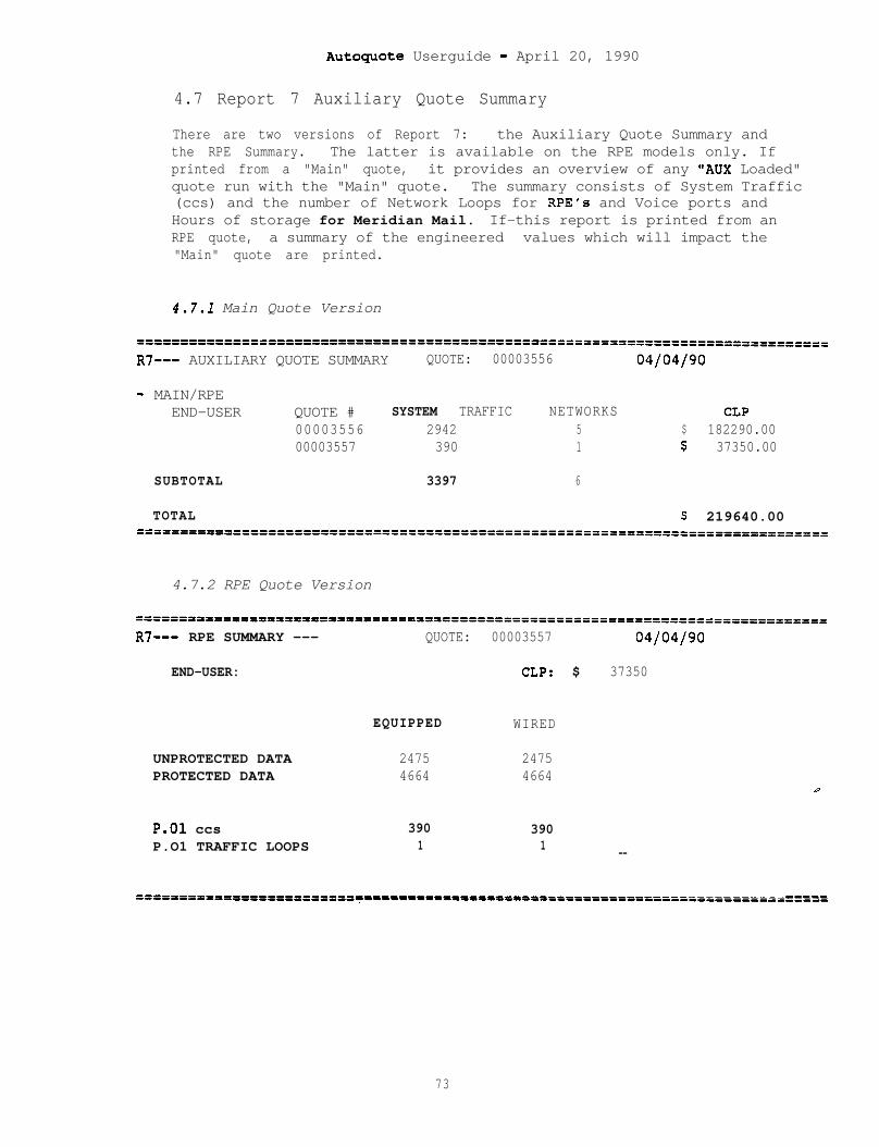
Autoguote Userguide - April 20, 1990
4.7 Report 7 Auxiliary Quote Summary
There are two versions of Report 7: the Auxiliary Quote Summary andthe RPE Summary. The latter is available on the RPE models only. Ifprinted from a "Main" quote, it provides an overview of any "AUX Loaded"quote run with the "Main" quote. The summary consists of System Traffic(ccs) and the number of Network Loops for RPE's and Voice ports andHours of storage for Meridian Mail. If-this report is printed from anRPE quote, a summary of the engineered values which will impact the"Main" quote are printed.
4.7.1 Main Quote Version
=---------======================================================-------=-----==R7--- AUXILIARY QUOTE SUMMARY QUOTE: 00003556 04/04/90
- MAIN/RPEEND-USER QUOTE # SYSTEM TRAFFIC NETWORKS CLP
00003556 2942 5 $ 182290.0000003557 390 1 $ 37350.00
SUBTOTAL 3397 6
TOTAL $ 219640.00=========r=====================================================================
4.7.2 RPE Quote Version
======P’=========35oleo==========’==================================================
R7--- RPE SUMMARY --- QUOTE: 00003557 04/04/90
END-USER: CLP: $ 37350
EQUIPPED WIRED
UNPROTECTED DATA 2475 2475PROTECTED DATA 4664 4664
P.01 ccsP.O1 TRAFFIC LOOPS
390 3901 1 --
=tn=3=pmtr=3nplmrrnrtntor--------------------------------------------------------e-m‘-----------------------------------------------------
73
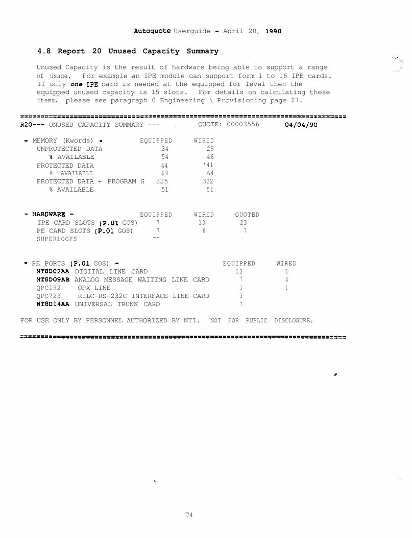
Autoquote Userguide - April 20, 1990
4.8 Report 20 Unused Capacity Summary
Unused Capacity is the result of hardware being able to support a rangeof usage. For example an IPE module can support form 1 to 16 IPE cards.If only one IPE card is needed at the equipped for level then theequipped unused capacity is 15 slots. For details on calculating theseitems, please see paragraph 0 Engineering \ Provisioning page 27.
R20--- UNUSED CAPACITY SUMMARY --- . QUOTE: 00003556 04/04/90
- MEMORY (Kwords) - EQUIPPED WIREDUNPROTECTED DATA 34 29
% AVAILABLE 54 46PROTECTED DATA 44 '41
% AVAILABLE 69 64PROTECTED DATA + PROGRAM S 325 322
% AVAILABLE 51 51
-HARDWARE- EQUIPPED WIREDIPE CARD SLOTS (P.01 GOS) 7 13PE CARD SLOTS (P-01 GOS) 7 6SUPERLOOPS --
- PE PORTS (P.01 GOS) -NTEDOZAA DIGITAL LINE CARDNT8D09AB ANALOG MESSAGE WAITING LINE CARDQPC192 OPX LINEQPC723 RILC-RS-232C INTERFACE LINE CARDNT8D14AA UNIVERSAL TRUNK CARD
QUOTED237
EQUIPPED137137
WIRED541
FOR USE ONLY BY PERSONNEL AUTHORIZED BY NTI. NOT FOR PUBLIC DISCLOSURE.
*.
74
‘,

Autoquote Userguide - April 20, 1990
4.8.1 Memory
Unused memory capacities are calculated and displayed when appropriate,e.g. UNPROTECTED DATA, PROGRAM STORE + P-DATA, and TOTAL MEMORY. Allvalues are in words of memory. % AVAILABLE.is also calculated for eachmemory category.
4.8.2 Hardware
PE CARD SLOTS (P.01 GOS) are the number of card slots available on P.01PE shelves in the configured system. Unused card slots for the Quotedconfiguration mayebe large since modules are quoted at the Wiredquantity while PE cards are quoted at the Equipped quantity.
SUPERLOOPS is the number of loops that may be added to the existingCE/NET modules.
4.8.3 PE Ports
This section displays the spare number of ports for each line card typein the system at the Equipped and Wired levels.. REPORTS
75

Autoquote Userguide - April 20, 1990

Autoquote Userguide - April 20, 1990
5. AUXILIARY LOADING
Auxiliary Loading is used to combine the engineering of one or moreperipheral devices with a main system. Auxiliary Loading is requiredsince each system, peripheral or main,- is a unique quote with a uniquequote number. As an example, one or more Remote 'Peripheral Equipment(RPE) quotes can be Aux Loaded onto a main quote (Option 21,51,61 or71). Note that Aux Loading DOES NOT COMBINE QUOTES together, but simplyallows the main to be configured with the necessary equipment to supportthe peripheral/auxiliary systems. Please reference theEngineering/Provisioning Section on RPE and Meridian Mail for specificson these products.
The general procedure of how to use the Auxiliary Load function is asfollows:
1) Create, save and run reports for all auxiliary quotes.Although it is not necessary to print all reports, the Reportfunction must be initiated for each Auxiliary quote to calculatethe required information for inclusion into the Main quote. Ifdesired, Reports for each Auxiliary quote may be printed in thenormal manner.
2) Create the Main quote (or Load the main quote if alreadycreated). Make sure all required software to support theperipherals has been included on the Main quote. At the servicemenu, enter "X" for Aux Load (refer to the Introduction/Overviewchapter for how to select the Aux Load command from the ServiceMenu). At this point, the system will prompt you for:
PLEASE ENTER AUI[QUOTE NUMBER OR END
Enter the quote number of the first Auxiliary quote. Since morethan one Auxiliary quote can be combined with the Main quote, thesystem will continue to prompt for Auxiliary quote numbers until"END" is entered.
3) After "END" has been entered for step 2, the Service Menu willbe displayed. At this point, Reports can be selected for the Mainsite by entering "R". The configuration calculated and printedfor this main quote will contain the necessary equipment requiredto support the peripheral quotes Aux Loaded.. ‘-The Auxiliary QuoteSummary Report.(7) and the Auxiliary Price- Summary Report (11) maybe printed to verify the Aux Load quote numbers.
The Main quote and any Auxiliary quotes remain separate quotes. The AuxLoad function simply allows the main quote to be configured to supportauxiliary sites. The list of Aux Load quotes are not saved with theinput data of the main quote. Therefore, the process of entering theauxiliary quotes as described in step 2 above should be completed eachtime the main quote is loaded.*.
If any changes are made to the auxiliary quotes, the Reports option (R)
77

Autoquote Userguide - April 20, 1990
must be selected for each auxiliary quote changed. By doing this, anyconfiguration changes are calculated and saved for inclusion in the Mainquote. Likewise, the Main quote will have to be re-run Aux Loading theauxiliaries with the above steps.
.
78

Autoquote Userguide - April 20, 1990
6. APPENDIX 1: INPUT FORM
QUOTATION REQUEST FORM Autoquote Numbers:TELENET: 214156301-7764
Salesman Name: Type of Quote: 1, 2 or 3
City/Labor-Code: End-User Industry Code:
End-User Company Name:
End-User Location:
System Cutover Date (MMDDYY):
Model/Generic Code: Release:
Report Options:1 = Price Summary 3 = Equipment List4 = Engineering Summary' 5 = Equipment Summary6 = Input Listing 7 = RPE Summary9 = Equipment List 11 = Auxiliary Load Summary
15 = Discount Summary 20 = Unused Capacity Summary
.
7 9
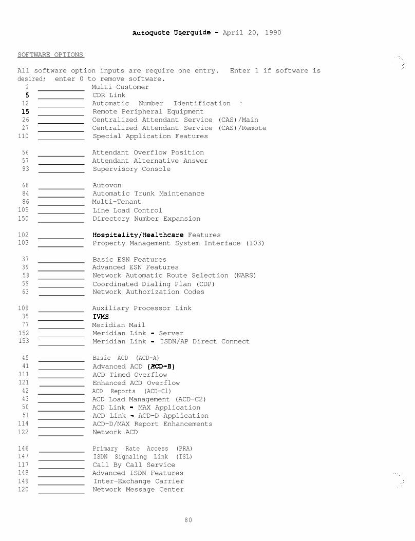
Autoguote Userguide - April 20, 1990
SOFTWARE OPTIONS
All software option inputs are require one entry. Enter 1 if software isdesired; enter 0 to remove software.
2 Multi-Customer5 CDR Link
12 Automatic Number Identification -15 Remote Peripheral Equipment26 Centralized Attendant Service (CAS)/Main27 Centralized Attendant Service (CAS)/Remote
110 Special Application Features
56 Attendant Overflow Position57 Attendant Alternative Answer93 Supervisory Console
68 Autovon84 Automatic Trunk Maintenance86 Multi-Tenant
105 Line Load Control150 Directory Number Expansion
102 Hospitality/Healthcare Features103 Property Management System Interface (103)
37 Basic ESN Features39 Advanced ESN Features58 Network Automatic Route Selection (NARS)59 Coordinated Dialing Plan (CDP)63 Network Authorization Codes
1093577
152153
4541
11112142435051
114122
Auxiliary Processor LinkIVMSMeridian MailMeridian Link - ServerMeridian Link - ISDN/AP Direct Connect
Basic ACD (ACD-A)Advanced ACD (ED-B)ACD Timed OverflowEnhanced ACD OverflowACD Reports (ACD-Cl)ACD Load Management (ACD-C2)ACD Link - MAX ApplicationACD Link - ACD-D ApplicationACD-D/MAX Report EnhancementsNetwork ACD
146 Primary Rate Access (PRA)147 ISDN Signaling Link (ISL)117 Call By Call Service148 Advanced ISDN Features149 Inter-Exchange Carrier120 Network Message Center
80
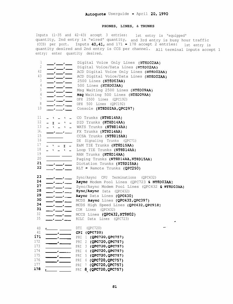
Autoquote Userguide - April 20, 1990
PHONES, LINES, t TRUNKS
Inputs (l-35 and 42-43) accept 3 entries: 1st entry is "equipped"quantity, 2nd entry is "wired" quantity, and 3rd entry is busy hour traffic(CCS) per port. Inputs 40,41, and 171 - 178 accept 2 entries: 1st entry isquantity desired and 2nd entry is CCS per channel. All terminal inputs accept 1entry; enter quantity desired.
1 -'-I-2
4243345678
10
11121314.151617181920
-‘-‘-
-‘-‘-
-‘-‘-
-‘-‘-
-‘-‘-
-‘-‘-
m m’-I
-‘-‘-
-‘-‘-
-‘-I-
- ‘ - ‘ -- I - ‘ -- ‘ - ‘ -m’-‘-
- ‘ - I -- ‘ - ‘ -
32 w'-'-35 -'-I-
40 I41
i71172173174175176177
I--
-‘-
-‘-
-‘-
-‘-
-‘-
178 t
Digital Voice Only Lines (NT8D02AA)Digital Voice/Data Lines (NTBDOZAA)ACD Digital Voice Only Lines (NT8D02AA)ACD Digital Voice/Data Lines (NT8D02AA)2500 Lines (NT8D03AA)500 Lines (NT8D03AA)Msg Waiting 2500 Lines (NTBDO9AA)Msg Waiting 500 Lines (NT8D09AA)OPX 2500 Lines (QPC192)OPX 500 Lines (QPC192)Console (NT8D02AA,QPC297)
CO Trunks (NT8D14AA)DID Trunks (NT8D14AA)WATS Trunks (NT8D14AA)FX Trunks (NT8D14AA)CCSA Trunks (NT8DlSAA)DX Signaling Trunks (QPC71)E&M TIE Trunks (NT8DlSAA)Loop TIE Trunks (NT8D14AA)RAN Trunks (NT8DlQAA)Paging Trunks (NTBD14AA,NT8D15AA)Dictation Trunks (NT8DlSAA)RLT - Remote Trunks (QPC250)
Sync/Async CPU Terminations (QPC432)Async Modem Pool Lines (QPC723 t NT8D03AA)Sync/Async Modem Pool Lines (QPC432 & NT8DO3AA)Sync/Async Data (QPC432)Async Data Lines (QPC430)MCDS Async Lines (QPC432,QPC397)MCDS High Speed Lines (QPC432,QPC918)CIM Lines (QPC432)MCCS Lines (QPC432,NT9N02)RILC Data Lines (QPC723)
DTI (QPC720)CPI (QPC720)PRI 1 (QPC72O,QPC757)PRI 2 (QPC72O,QPC757)PRI 3 (QPC72O,QPC757)PRI 4 (QPC72O,QPC757)PRI 5 (QPC72O,QPC757)PRI 6 (QPC72O,QPC757)PRI 7 (QPC720,QPC757)PRI 8c(QPC720,QPC757)
_-
8'1
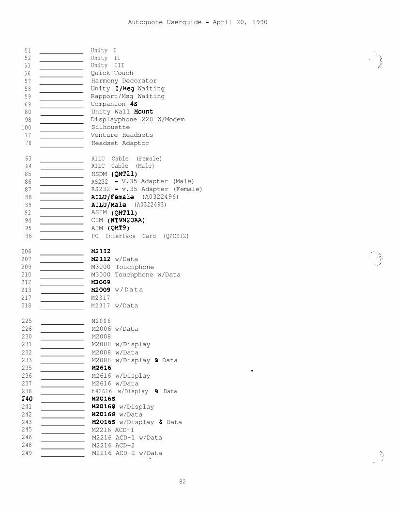
Autoquote Userguide - April 20, 1990
51 Unity I52 Unity II53 Unity III56 Quick Touch57 Harmony Decorator58 Unity I/Msg Waiting59 Rapport/Msg Waiting69 Companion 4580 Unity Wall Mount98 Displayphone 220 W/Modem
100 Silhouette77 Venture Headsets78 Headset Adaptor
63 RILC Cable (Female)64 RILC Cable (Male)85 HSDM (QMT21)86 RS232 - V.35 Adapter (Male)87 RS232 - v.35 Adapter (Female)88 AILU/Female (A0322496)89 AILU/Male (A0322493)92 ASIM (QMTll)94 CIM (NT9N20AA)95 AIM (QMTS)96 PC Interface Card (QPCS12)
206 M2112207 M2112 w/Data209 M3000 Touchphone210 M3000 Touchphone w/Data212 I42009213 M2009 w/Data217 M2317218 M2317 w/Data
2252262302312322332352362372382.40241242243245246248249
M2006M2006 w/DataM2008M2008 w/DisplayM2008 w/DataM2008 w/Display & DataM2616M2616 w/DisplayM2616 w/Datat42616 w/Display 6 DataM2016SM2016S w/DisplayM2016S w/DataM2016S w/Display & DataM2216 ACD-1M2216 ACD-1 w/DataM2216 ACD-2M2216 ACD-2 w/Dataw.
82
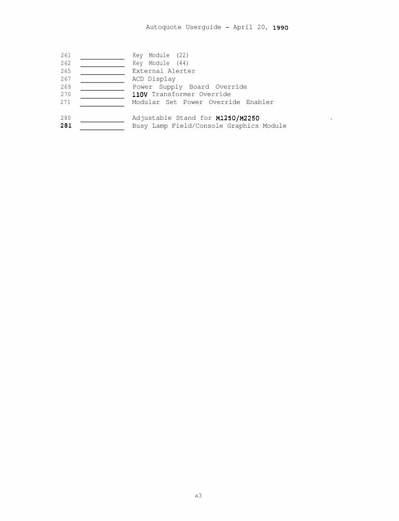
261262265267269270271
280281
Autoquote Userguide - April 20, 1990
Key Module (22)Key Module (44)External AlerterACD DisplayPower Supply Board Override1lOV Transformer OverrideModular Set Power Override Enabler
Adjustable Stand for Ml250/M2250Busy Lamp Field/Console Graphics Module
a3
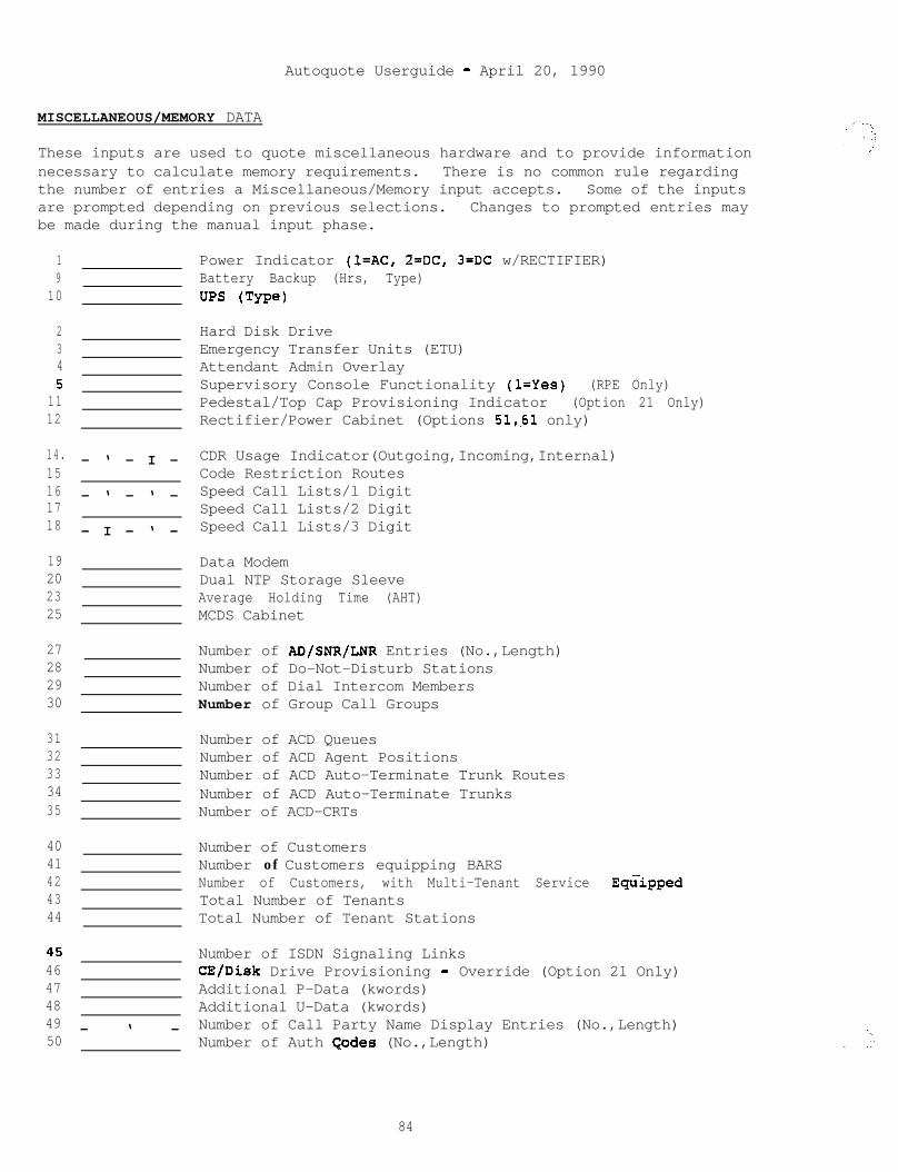
Autoquote Userguide - April 20, 1990
MISCELLANEOUS/MEMORY DATA
These inputs are used to quote miscellaneous hardware and to provide informationnecessary to calculate memory requirements. There is no common rule regardingthe number of entries a Miscellaneous/Memory input accepts. Some of the inputsare prompted depending on previous selections. Changes to prompted entries maybe made during the manual input phase.
1 Power Indicator (l=AC, 2=DC, 3=DC w/RECTIFIER)9 Battery Backup (Hrs, Type)
10 UPS (Type)
2 Hard Disk Drive3 Emergency Transfer Units (ETU)4 Attendant Admin Overlay5 Supervisory Console Functionality (l=Yes) (RPE Only)
11 Pedestal/Top Cap Provisioning Indicator (Option 21 Only)12 Rectifier/Power Cabinet (Options 51,61 only)
14.15161718
19 Data Modem20 Dual NTP Storage Sleeve23 Average Holding Time (AHT)25 MCDS Cabinet
27 Number of AD/SNR/LNR Entries (No.,Length)28 Number of Do-Not-Disturb Stations29 Number of Dial Intercom Members30 Number of Group Call Groups
31 Number of ACD Queues32 Number of ACD Agent Positions33 Number of ACD Auto-Terminate Trunk Routes34 Number of ACD Auto-Terminate Trunks35 Number of ACD-CRTs
4041424344
454647484950
- ‘ - I -
- ‘ - ‘ -
- I - ‘ -
- ‘ -
CDR Usage Indicator(Outgoing,Incoming,Internal)Code Restriction RoutesSpeed Call Lists/l DigitSpeed Call Lists/2 DigitSpeed Call Lists/3 Digit
Number of CustomersNumber of Customers equipping BARSNumber of Customers, with Multi-Tenant Service Eq&ppedTotal Number of TenantsTotal Number of Tenant Stations
Number of ISDN Signaling LinksCE/Disk Drive Provisioning - Override (Option 21 Only)Additional P-Data (kwords)Additional U-Data (kwords)Number of Call Party Name Display Entries (No.,Length)Number of Auth C,odes (No.,Length)
84

Autoquote Userguide - April 20, 1990
21 Additional SD1 Ports37 Additional SD1 Ports for APLs38 Additional Conference Cards for MOH/AwU39 Additional ESDI Ports
85
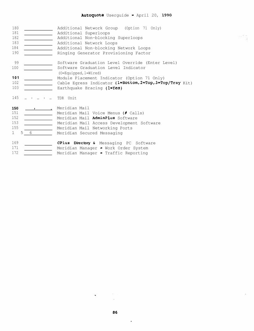
Autoguote Userguide - April 20, 1990
180181182183184190
99100
1 0 1102103
145 - ' - ' -
150 I ,1511521531551 5 6
169 CPlus Directory & Messaging PC Software171 Meridian Manager - Work Order System172 Meridian Manager - Traffic Reporting
Additional Network Group (Option 71 Only)Additional SuperloopsAdditional Non-blocking SuperloopsAdditional Network LoopsAdditional Non-blocking Network LoopsRinging Generator Provisioning Factor
Software Graduation Level Override (Enter Level)Software Graduation Level Indicator(O=Equipped,l=Wired)Module Placement Indicator (Option 71 Only)Cable Egress Indicator (l=Bottom,2=Top,3=Top/Tray Kit)Earthquake Bracing (l=Yes)
TDR Unit
Meridian MailMeridian MailMeridian MailMeridian MailMeridian Mail
Voice Menus (# Calls)AdminPlus SoftwareAccess Development SoftwareNetworking Ports
Meridian Secured Messaging
..-
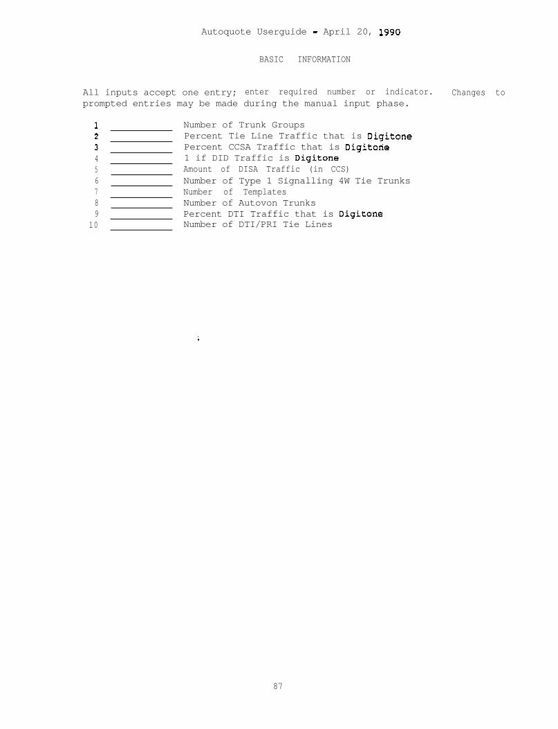
Autoquote Userguide - April 20, 1990
BASIC INFORMATION
All inputs accept one entry; enter required number or indicator. Changes toprompted entries may be made during the manual input phase.
1c1
;456789
10
Number of Trunk GroupsPercent Tie Line Traffic that is DigitonePercent CCSA Traffic that is Digitone1 if DID Traffic is DigitoneAmount of DISA Traffic (in CCS)Number of Type 1 Signalling 4W Tie TrunksNumber of TemplatesNumber of Autovon TrunksPercent DTI Traffic that is DigitoneNumber of DTI/PRI Tie Lines
87

Autoquote Userguide - April 20, 1990
N O N B L O C K I N G I N P U T S
PHONES, LINES, & TRUNKS
Non-blocking port inputs accept 3 entries: 1st entry is '.'equipped" quantity,2nd entry is "wired"port.
101 - ' - ' - NB102 -'-I- NB142 -'-'- NB143 -'-'- NB103 -'-I- NB104 -'-I- NB105 -'-I- NB106 -'-I- NB107 -I-'- NB108 -I-'- NB110 -'-'- NB
111 -'-I- NB112 -'-I- NB113 -'-I- NB114 -t-r NB115 -t-r- NB
-116 - ' - ' - NB117 - ' - ' - NB118 -'-I- NB119 -'-I- NB120 -I I NB121 -'-I- NB122 -'-I- NB
123 I I NB124 , 7 NB127 , 7 NB128 , t- NB129 I I NB130 -t-,- NB
-134 -'-I- NB131 -I-'- NB132 -'-I- NB135 -'-I- NB
quantity, and 3rd entry is busy hour traffic (CCS) per
Digital Voice Only Lines (NT8D02AA)Digital Voice Only Lines (NT8D02AA)Digital Voice Only Lines (NT8D02AA)Digital Voice/Data Lines (NT8DOZAA)2500 Lines (NT8D03AA)500 Lines (NT8D03AA)Msg Waiting 2500 Lines (NT8D09AA)Msg Waiting 500 Lines (NT8DOSAA)OPX 2500 Lines (QPC192)OPX 500 Lines (QPC192)Console (NT8D02AA)
CO Trunks (NT8D14AA)DID Trunks (NT8D14AA)WATS Trunks (NT8D14AA)FX Trunks (NT8D14AA)CCSA Trunks (NT8DlSAA)DX Signalling Trunks (QPC71)E&M TIE Trunks (NT8DlSAA)Loop TIE Trunks (NT8D14AA)RAN Trunks (NT8D14AA)Paging Trunks (NT8D14AA)Dictation Trunks (NT8D15AA)RLT - Remote (QPC250)
Sync/Async CPU Terminations (QPC432)Async Modem Pool Lines (QPC723 & NT8D03AA)Sync/Async Modem Pool Lines (QPC432 & NT8D03AA)Sync/Async Data (QPC432)Async Data Lines (QPC430)MCDS Async Lines (QPC432,QPC397)'MCDS High Speed Lines (QPC432,QPC918)CIM Lines (QPC432)MCCS Lines (QPC432,NT9N02)RILC Data Lines (QPC723)
88
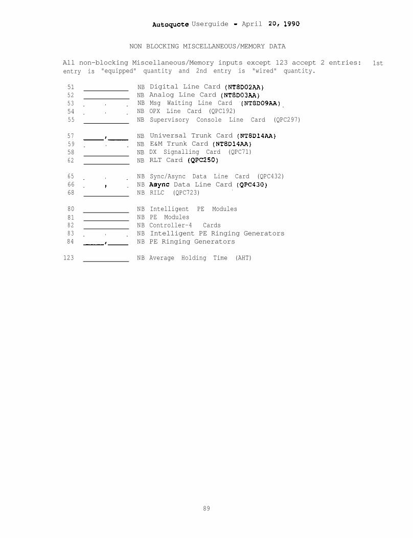
AutoquOte Userguide - April 20, 1990
NON BLOCKING MISCELLANEOUS/MEMORY DATA
All non-blocking Miscellaneous/Memory inputs except 123 accept 2 entries: 1stentry is "equipped" quantity and 2nd entry is "wired" quantity.
5152535455
57595862
656668
8081828384
123 NB Average Holding Time (AHT)
- ‘ -
- ‘ -
-‘-
- ‘ -
- ‘ -I- -
- ‘ -
-‘-
NB Digital Line Card (NT8D02AA)NB Analog Line Card (NT8D03AA)NB Msg Waiting Line Card -(NT8D09AA).NB OPX Line Card (QPC192)NB Supervisory Console Line Card (QPC297)
NB Universal Trunk Card (NT8D14AA)NB E&M Trunk Card (NT8D14AA)NB DX Signalling Card (QPC71)NB RLT Card (QPC250)
NBNBNB
NB Intelligent PE ModulesNB PE ModulesNB Controller-4 CardsNB Intelligent PE Ringing GeneratorsNB PE Ringing Generators
Sync/Async Data Line Card (QPC432)Async Data Line Card (QPC430)RILC (QPC723) .
89

--
Meridkm I
AUTOQUOTE USER GUIDE
MERIDIAN MAIL
ntt northerntolecom

:
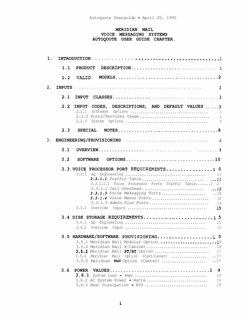
Autoquote Userguide - April 20, 1990
MERIDIAN MAILVOICE MESSAGING SYSTEMS
AUTOQUOTE USER GUIDE CHAPTER.
1. INTRODUCTION . . . . . . . . . . . . . . . ..t........................... 1
1.1 PRODUCT DESCRIPTION.................. . . . . . . . . . . . . . 1
1.2 VALID MODELS......................................2
2. INPUTS . . . . . . . . . . . . . . . . . . . . . . . . . . . . . . . . . . . . . . . . . . . . . . . . . . 2
2.1 INPUT CLASSES.............. . . . . . . . . . . . . . . . . . . . . . . . 2
2.2 INPUT CODES, DESCRIPTIONS, AND DEFAULT VALUES .. ...32.2.1 Software Options ..................................... 32.2.2 Ports/Services Usage ................................. 42.2.3 System Options ....................................... 6
2.3 SPECIAL NOTES.....................................8
3. ENGINEERING/PROVISIONING . . . . . . . . . . . . . . . . . . . . . . . . . . . . . . . . a
3.1 OVERVIEW................. . . . . . . . . . . . . . . . . . . . . . . . . . 9
3.2 SOFTWARE OPTIONS.................................10
3.3 VOICE PROCESSOR PORT REQUIREMENTS.................1 03.3.1 AQ Engineering ...................................... 11
3.3.1.1 Traffic Table ............................. ..ll3.3.1.1.1 Voice Processor Ports Traffic Table.......1 23.3.1.2 Call Overhead ............................. ..123.3.1.3 Voice Messaging Ports ..................... ..143.3.1.4 Voice Menus Ports ........................... 143.3.1.5 Admin Plus Ports ............................ 14
3.3.2 Override Inputs ..................................... 1s
3.4 DISK STORAGE REQUIREMENTS........................1 53.4.1 AQ Engineering ...................................... 153.4.2 Override Input ...................................... 15
3.5 HARDWARE/SOFTWARE PROVISIONING....,..............1 53.5.1 Meridian Mail Modular Option . ..a..'...................1 63.5.2 Meridian Mail X-Cabinet ............................. 163.5.3 Meridian Mail ST/RT Option .......................... 173.5.4 Meridian Mail Option (Cantilever) ................. ..173.5.5 Meridian Mail Option (Center) ..................... ..17
3.6 POWER VALUES.....................................1 93.6.1 System Load - Amps .................................. 193.6.2 AC System Power - Watts ............................. 193.6.3 Heat Dissipation - BTU .............................. 19
Autoquote Userguide - April 20, 1990
3.7 MERIDIAN 1 EQUIPMENT PROVISIONING................2 03.7.1 ROM Card............................................2 03.7.2 ESDI Card...........................................2 03.7.3 Other Equipment ..................................... 21
3.8 MERIDIAN 1 IMPACT................................2 13.8.1 Memory.........................;....................2 1
3.8.1.1 Program Store. .............................. 213.8.1.2 Protected Data/Unprotected Data.............2 13.8.1.3 Protected Data*............................... 223.8.1.4 Unprotected Data : ........................... 22
3.8.2 Real Time ........................................... 223.8.3 Network Cards ....................................... 233.8.4 Traffic .............................................. 233.8.5 Meridian Mail Integration Considerations............2 3
3.8.5.1 Meridian Mail Modular Option................2 43.8.5.2 Meridian Mail X-Cabinet.....................2 43.8.5.3 Meridian Mail ST/RT Option..................2 43.8.5.4 Meridian Mail Shelf Option..................2 4
4. REPORTS . . . . . . . . . . . . . . . . . . . . . . . . . . . . . . . . . . . . . . . . . . . . . . . . 25
4.1 Report 1 - Price Summary.. . . . . . . . . . . . . . . . . . . . . ...26
4.2 Report 4 - Engineering Summary....................2 74.2.1 Voice Messaging Usage ............................... 274.2.2 Dedicated Voice Port Services.......................2 84.2.3 Voice Storage ....................................... 28
4.3 Report 6 - Input Listing..........................30
4.4 Report 9 - Equipment List........................31
4.5 Report 17 - Circuit Switch Impact................32
4.6 Report 21 - Power Summary........................34
5. APPENDIX 1: INPUT FORM . . . . . . . . . . . . . . . . . . . . . . . . . . . . . . . . 35
_-
ii
AutoquOte Userguide - April 20, 1990
1 . INTRODUCTION
This chapter of the Meridian 1 Communication Systems Autoquote UserGuide provides information on quoting the Meridian Mail Modular Option,the Meridian Mail X-Cabinet, the Meridian Mail ST/RT Option tier, theMeridian Mail Option shelf. It includes the following sections:
Section 1: IntroductionSection 2: InputsSection 3: Engineering/ProvisioningSection 4:. Reports
The mechanics of using Autoquote are not included in this productchapter. Refer to the Introduction and Overview chapter for detailedinformation on how to use the Autoquote System.
1.1 PRODUCT DESCRIPTION
Meridian Mail is a dedicated voice services peripheral device which isfunctionally integrated with the Meridian 1.
This system can be integrated with the SL-lST, MS, RT, LE, N, NT, XL,XN, XT, and all of the Meridian 1 products. The other versions of theproduct are the Meridian Mail ST/RT Option and the Meridian Mail Option(for SL-lMS, LE, N, NT, XL, XN, and XT).
All of these Meridian Mail versions interface to the Meridian 1 CircuitSwitch via an Enhanced Serial Data Interface (ESDI) port and networkloops (QPC414). The ST/RT Option and Shelf Option will support up to 20ports and 114 hours of voice storage. The Modular Option and X-Cabinetwill support up to 48 ports and 240 hours of storage.
. . l
1
Autoquote Userguide - April 20, 1990
1.2 VALID MODELS
There are two valid Meridian Mail Autoquote models.
ModelGeneric Code Release__-___----------------------------------------Meridian Mail MM <RETURN>On-line Input Form MMF <RETURN>
Neither of the models has an associated release; i.e. enter RETURN atthe release prompt.
Meridian Mail may be guoted.two ways with the "MM" model. The first wayis to quote the Meridian Mail system as merchandise. The second way isto quote it along with a Meridian 1 system using the "AUX LOAD"function. (See the Meridian 1 Product Chapter in this User Guide formore information on using the "AUX LOAD" function in conjunction withthe "MM" generic.)
** All of the versions of the product may be "AUX LOADED" onto aMeridian 1 configuration except the center mount Meridian Mail Option.
2. INPUTS
This section covers all inputs associated with the Meridian Mailgeneric. The following subsections are contained within this section:
Input ClassesInput Codes, Descriptions, and Default ValuesSpeci'al Notes
As with all Autoquote models, data input consists of responses toprompted entries and manual inputs associated with specific input codes.A blank input form is included in the back of this chapter. It isrecommended that copies be used for preparing quotations. An on-lineinput form is also available on the Autoquote system (Generic Code"MMF" ) .
2.1 INPUT CLASSES _-
Meridian Mail inputs are organized into three input classes:
Software Options [AlPorts/Services Usage .[PlSystem Options [Sl
The Autoquote will prompt for each input class in the order listed abovewhen setting up a new quote. The letter designation is used to makeselections for that input class from the Input Menu.
2
AutOquOte Userguide - April 20, 1990
2.2 INPUT CODES, DESCRIPTIONS, AND DEFAULT VALUES
The following pages contain information on each Meridian Mail input:codes, descriptions, and default values where appropriate.
2.2.1 Software Options
All Software Option inputs accept one entry. Enter one (1) if thesoftware option is desired; enter zero (0) to remove a softwareoption.
1 Meridian Mail
This input is used to provision the base Meridian MailSoftware. This input will automatically be selected byAutoquOte if necessary. Autoquote will also select theappropriate Meridian Mail options depending on the number ofvoice processor ports and hours of storage quoted.
2 Voice Menus Options
This will provision Meridian Mail voice menus software.
3 Meridian Mail Networking
This input provisions Meridian Mail Networking software.
50 Meridian Mail Admin Plus
This input provisions Meridian Mail Admin Plus software.
51 Access Development Software
This input provisions Access Development software. MeridianMail Admin Plus (input 50) is a prerequisite for thisoption.
3

Autoquote Userguide - April 20, 1990
2.2.2 Ports/Services Usage
There is no common rule regarding the number of entries a Ports/ServicesUsage input may accept. Refer to the input sheet or the informationprovided below for the number of entries each input accepts..
1 Voice Messaging Users
This input is used to determine the appropriate'number ofvoice processor ports and hours of storage needed on thesystem based on usage. It accepts three entries.
o Number of Registered Users
If no entry is made, this input will default to 1.
o Seconds of Usage during the Busy Hour
Default is 39 seconds.
o Voice Storage in minutes for each user
Default is 1.6 minutes.
5 Networking Ports
Enter the number of networking ports desired.
10 Voice Menus (No.,Hours)
This input accepts two entries.
0 Number of Menus
Maximum allowed is 1000. If no entry is made, thisinput will be set to the number of separate Voice Menugroups specified via Voice Menu Usage inputs 11-14.
o Hours of Storage for all Voice Menus
:‘.
Maximum allowed is 48 hours (24 hours for the ST/RTand Shelf Options); the default is 1 hour.
--
4
Autoquote Userguide - April 20, 1990
11 Voice Menu Usage12 Voice Menu Usage13 Voice Menu Usage14 Voice Menu Usage
These inputs accept two entries, and are used to specifydifferent amounts of traffic for the different menus used inthe system.
o Number of Voice Menu Calls during the Busy Hour
o Average Holding Time per Menu Call in Seconds
The default is 25 seconds. Multiple inputs areavailable so that different menu groups with varyingusage characteristics can easily be entered. If nousage is entered and Voice Menu software is selected,input 11 will default to 1 for the first value,and 25for the second value.
20 Voice Menu Usage Indicator (l=Dedicated)
Enter one (1) if the Voice Menu traffic is dedicated, i.e.ports for menu use will not be shared with ports used forVoice Messaging. Making an entry in the Voice Menu Portsoverride input (Systems Option input 53) also results indedicated menu ports.
Dedicating Voice Menu ports will generally result in morevoice processor ports being provisioned on a system becauseof a loss in traffic carrying efficiency.
21 Networking Usage Indicator (l=Dedicated)
Enter one (1) if the Networking traffic is dedicated, i.e.ports for networking use will not be shared with ports usedfor normal Voice Messaging.
Dedicating Networking ports will generally result in morevoice processor ports being provisioned on a system becauseof a loss in traffic carrying efficiency.
50 Admin Plus Usage (Access)- -
Meridian Mail Admin Plus (Software input 50) is aprerequisite for this application.. This input accepts twoentries.
o Number of Admin Plus Access Ports required
o Storage in Hours for Admin Plus applications
Default is 1 hour.c
5
Autoquote Userguide - April 20, 1990
51 Meridian Mail PC Users (Access)
* Meridian Mail Admin Plus (Software input 50) is aprerequisite for this application. This input accepts threeentries. .
o Number of Registered Users
o Seconds of Usage during the Busy Hour- Default is 80 seconds.
o Voice Storage in Minutes for each User- Default is 4 minutes.
2.2.3 System Options
All inputs accept 1 entry; enter desired number or indicator. The systemwill default to the Meridian Mail Modular Option (Input 47) when settingup a new quote.
2 Distribution Lists3 Spoken Names
Enter the desired number of each. Both of these inputs,along with the number of registered users, will impact voicestorage capacity.
5 Modular Option Power
This input will default to- zero (0); for AC power. If DCpower is required, enter a one (1) for this input.
21 Model Indicator
This input will be prompted when running a new quote.
Valid entries are:1 = LE (SINGLE CPU)2 = LE (DUAL CPU)3 = N (SINGLE CPU)4 = N (DUAL CPU)s=xL6 = XN (w/MEMORY ENHANCEMENT) --7 = XN (w/out MEMORY ENHANCEMENT)>8 = RT/NT9=XT10 = ST11 f MS12 = Options 21,51,61,71 '
6
AutOquOte Userguide - April 20, 1990
This input indicates what type of Circuit Switch theMeridian Mail system will be interfacing. It is used todetermine if a ROM card must be included in the MeridianMail quote and to calculate Circuit Switch memory and realtime impact of the Meridian Mail system.
47 Meridian Mail Modular Option Indicator (1 = Modular Option)48 Meridian Mail X-Cabinet Indicator (1 = X-Cabinet)
Enter a one (1) to indicate the option desired. Whensetting up a new quote, the system will default to theMeridian Mail Modular Option.
49 Meridian Mail Option Indicator
This input is used to quote the other Meridian Mail Options.Valid entries are:
1 = Meridian Mail ST/RT Option (Tier)2 = Meridian Mail Shelf Option (Cantilever Mount)3 = Meridian Mail Shelf Option (Center Mount)
The cantilever mount version of the Meridian Mail Option is*used for SL-1 systems utilizing the front/rear entry PEcabinets. The center mount version of the Meridian MailOption is used for SL-1 systems utilizing the front entryonly PE cabinets.
50 System Purchase Indicator (l=No)
Enter 1 if the Meridian Mail system is not purchased with aMeridian 1 system, i.e. the quote is for a merchandisepurchase. No entry or an entry of zero (0) will indicatethat this Meridian Mail configuration is part of a systempurchase.
51 Voice Messaging Ports (Optional Override)
This input allows the user to specify the number of voiceprocessor ports for Voice Messaging; this value overridesrequirements based on usage inputs. This entry includesshared services (voice menus) when appropriate. The maximumis 48. .
- -52 Hours of Voice Storage (Optional Override)-
This input allows the user to specify the amount of totalvoice storage; this value overrides requirements calculatedbased on the usage inputs (Ports/Services Usage Inputs).The maximum is 240.
7

Autoguote Userguide - April 20, 1990
53 Voice Menu Ports - Dedicated (Optional Override)
This input allows the user to specify the number of voiceprocessor ports dedicated to all Meridian Mail Admin Plus(Access) applications; this value overrides requirementsbased on usage inputs. The maximum 48.
54 Admin Plus Access Ports (Optional Override)-
This input allows the user to specify the number of voiceprocessor ports dedicated to all Meridian Mail AccessGateway applications; this value overrides requirementsbased on the usage inputs. The maximum is 48.
2.3 SPECIAL NOTES
To run a simple Voice Messaging quote where the number of ports andamount of voice storage required are known, the following inputs are allthat have to be entered:
Software Options:
. l/l Meridian Mail
Ports/Services Usage:
l/x Voice Messaging Usersx = number of registered voice messaging users.Let the other two values default.
System Options:
21/y SL-1 Model Indicator
Y = appropriate SL-1 indicator (1-12)
51/a Voice Messaging Ports (Optional Override)
a = required ports
52/b Hours of Voice Messaging Storage (Opt.Override)a
b = required hours of voice storage. _-
3. ENGINEERING/PROVISIONING
This section contains the engineering/provisioning rules used to configure theMeridian Mail Modular Option, Meridian Mail X-Cabinet, and Meridian Mail ShelfOptions. As the engineering rules for these are very similar, they will only bedistinguished when different. The following subsections are contained within
.-‘i
./.: 2’
Autoquote Userguide - April 20, 1990
this section.
OverviewSoftware OptionsVoice Processor Port RequirementsDisk Storage RequirementsHardware/Software provisioningP o w e r V a l u e sMeridian 1 Equipment ProvisioningMeridian 1 Impact
3.1 OVERVIEW
A Meridian Mail configuration generated by Autoquote is based upon NT1engineering rules in effect as of the run date but prior to submission of anorder. Although engineering rules may change in the future, NT1 will honor thequoted functionality for 60 days from the run date. However, pricing isgoverned solely by the NT1 CPE Distributorship Agreement between eachdistributor and NTI, and the Meridian One Communication Systems Pricing Manualin effect on the date NT1 accepts the order.
The price quoted by the Autoquote applies only to the items of equipment andsoftware listed in the Equipment List report. This report contains a line entryfor each item of equipment and software that is quoted. No item is priced intothe quote unless it is detailed in this report. Pricing adjustments arerequired if there are any additions or deletions to this list:
The contents of any quote depends solely on the inputs and the engineeringrules. The actual configuration depends on particular applications andfinalized system engineering which may require manual additions or deletions. Inthis section, inputs will be used in some of the equations. The input classletter designation and code number will be used to represent specific inputs.The three input classes are:
Class Designation
Software Options [AlPorts/Services Usage [PISystem Options ISI
For example:
Pl(#f) - refers to Ports/Services Usage input land indicates thenumber of registered Voice Messaging users,
Pl(sec) - indicates the number of seconds of usage for each userduring the busy hour, and
Pl(min) - indicates the number of minutes of voice storage foreach user. Unless otherwise noted, the answers to allcalculations used in this subsection are rounded to thenext whole number.
%.
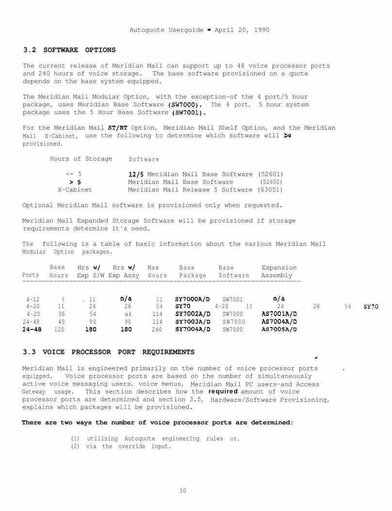
Autoguote Userguide - April 20, 1990
3.2 SOFTWARE OPTIONS
The current release of Meridian Mail can support up to 48 voice processor portsand 240 hours of voice storage. The base software provisioned on a quotedepends on the base system equipped.
The Meridian Mail Modular Option, with the exception-of the 4 port/5 hourpackage, uses Meridian Base Software (SW7000). The 4 port, 5 hour systempackage uses the 5 Hour Base Software (SW7001).
For the Meridian Mail ST/FIT Option, Meridian Mail Shelf Option, and the MeridianMail X-Cabinet, use the following to determine which software will $eprovisioned.
Hours of Storage Software
<= 5 12/5 Meridian Mail Base Software (52601)>5 Meridian Mail Base Software (52600)
X-Cabinet Meridian Mail Release 5 Software (63051)
Optional Meridian Mail software is provisioned only when requested.
Meridian Mail Expanded Storage Software will be provisioned if storagerequirements determine it's need.
The following is a table of basic information about the various Meridian MailModular Option packages.
Base Hrs w/ Hrs w/ Max Base Base ExpansionPorts Hours Exp S/W Exp Assy Hours Package Software Assembly------------------------------------------------------------------------
4-12 5 11 n/a 11 SY7000A/D SW7001'
n/a4-20 11 24 26 54 SY70 4-20 11 24 26 54 SY704-20 36 54 a4 114 SY7002A/D SW7000 AS70OlA/D
24-48 45 90 90 114 SY7003A/D SW7000 AS7004A/D24-48 120 180 la0 240 SY7004A/D SW7000 AS7005A/D
3.3 VOICE PROCESSOR PORT REQUIREMENTS
Meridian Mail is engineered primarily on the number of voice processor ports -equipped. Voice processor ports are based on the number of simultaneouslyactive voice messaging users, voice menus, Meridian Mail PC users-and AccessGateway usage. This section describes how the required amount of voiceprocessor ports are determined and section 3.5, Hardware/Software Provisioning,explains which packages will be provisioned.
There are two ways the number of voice processor ports are determined:
(1) utilizing Autoquote engineering rules or,(2) via the override input.
10

Autoguote Userguide - April 20, 1990
3.3.1 AQ Engineering
Autoquote engineering can be used to determine the number of voice processorports required for any or all parts of a Meridian Mail system. The Engineeringrules make use of Traffic Tables and Call Overhead to determine the number ofvoice processor ports needed for the system.
3.3.1.1 Traffic Table
When traffic is the usage parameter, a delay traffic table is used todetermine the number of required voice processor ports. The standardgrade of service is the probability that the delay-will be greater thanone-sixth the average holding time is equal to 5%. This delaycharacteristic can be expressed as follows:
Probability of Delay >> Holding Time/ 6 = 6%
11
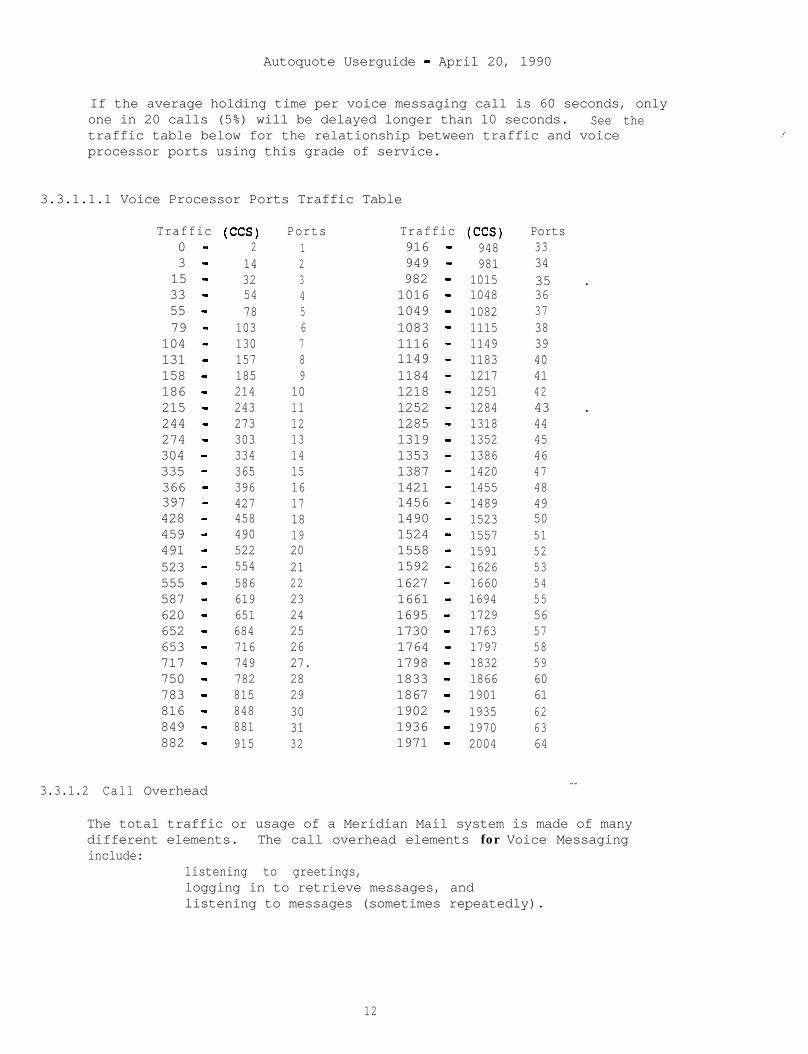
Autoquote Userguide - April 20, 1990
If the average holding time per voice messaging call is 60 seconds, onlyone in 20 calls (5%) will be delayed longer than 10 seconds. See thetraffic table below for the relationship between traffic and voiceprocessor ports using this grade of service.
3.3.1.1.1 Voice Processor Ports Traffic Table
Traffic (CCS)0 - 23 - 1415 - 3233 - 5455 - 7879 - 103
104 - 130131 - 157158 - 185186 - 214215 - 243244 - 273274 - 303304 - 334335 - 365366 - 396397 - 427428 - 458459 - 490491 - 522523 - 554555 - 586587 - 619620 - 651652 - 684653 - 716717 - 749750 - 782783 - 815816 - 848849 - 881882 - 915
3.3.1.2 Call Overhead
Ports123456789
101112131415161718192021222324252627.2829303132
Traffic (c-1 Ports916 - 948 33949 - 981 34982 - 1015 35 .1016 - 1048 361049 - 1082 371083 - 1115 381116 - 1149 391149 - 1183 401184 - 1217 411218 - 1251 421252 - 1284 43 .1285 - 1318 441319 - 1352 451353 - 1386 461387 - 1420 471421 - 1455 481456 - 1489 491490 - 1523 501524 - 1557 511558 - 1591 521592 - 1626 531627 - 1660 541661 - 1694 551695 - 1729 561730 - 1763 571764 - 1797 581798 - 1832 591833 - 1866 601867 - 1901 611902 - 1935 621936 - 1970 631971 - 2004 64
--
_’
The total traffic or usage of a Meridian Mail system is made of manydifferent elements. The call overhead elements for Voice Messaginginclude:
listening to greetings,logging in to retrieve messages, andlistening to messages (sometimes repeatedly).
12
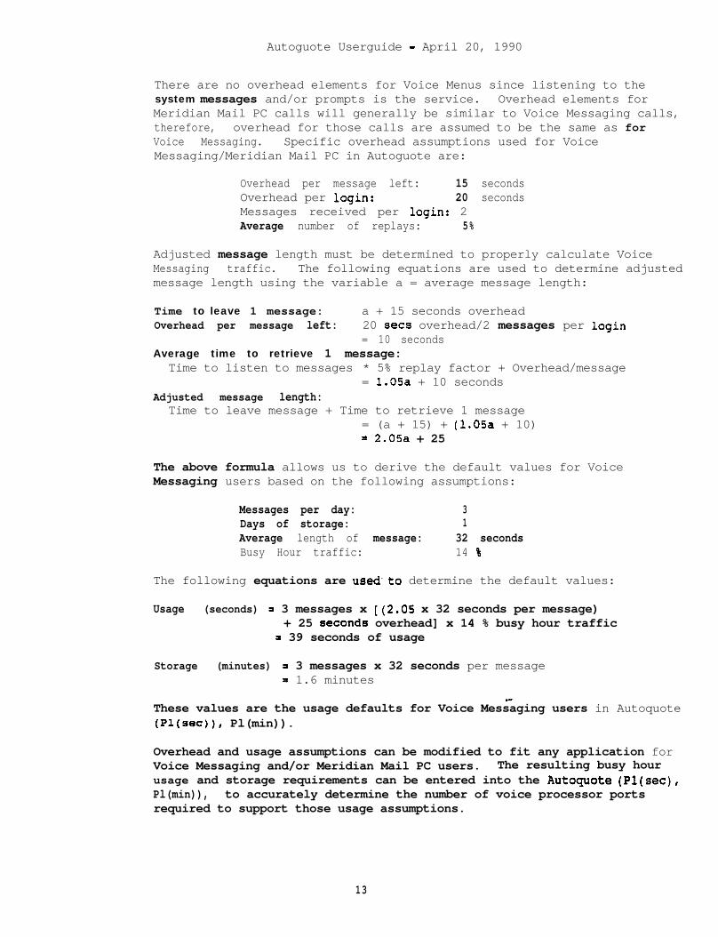
Autoguote Userguide - April 20, 1990
There are no overhead elements for Voice Menus since listening to thesystem messages and/or prompts is the service. Overhead elements forMeridian Mail PC calls will generally be similar to Voice Messaging calls,therefore, overhead for those calls are assumed to be the same as forVoice Messaging. Specific overhead assumptions used for VoiceMessaging/Meridian Mail PC in Autoguote are:
Overhead per message left: 15 secondsOverhead per login: 20 secondsMessages received per login: 2Average number of replays: 5%
Adjusted message length must be determined to properly calculate VoiceMessaging traffic. The following equations are used to determine adjustedmessage length using the variable a = average message length:
Time to leave 1 message: a + 15 seconds overheadOverhead per message left: 20 sets overhead/2 messages per login
= 10 secondsAverage time to retrieve 1 message:
Time to listen to messages * 5% replay factor + Overhead/message= 1.05a + 10 seconds
Adjusted message length:Time to leave message + Time to retrieve 1 message
= (a + 15) + (1.05a + 10)= 2.05a + 25
The above formula allows us to derive the default values for VoiceMessaging users based on the following assumptions:
Messages per day: 3Days of storage: 1Average length of message: 32 secondsBusy Hour traffic: 14 %
The following equations are used.to determine the default values:
Usage (seconds) = 3 messages x [(2.05 x 32 seconds per message)+ 25 seconds overhead] x 14 % busy hour traffic
= 39 seconds of usage
Storage (minutes) = 3 messages x 32 seconds per message= 1.6 minutes
_-These values are the usage defaults for Voice Messaging users in Autoquote(Pl(sec)), Pl(min)).
Overhead and usage assumptions can be modified to fit any application forVoice Messaging and/or Meridian Mail PC users. The resulting busy hourusage and storage requirements can be entered into the Autoquote (Pl(sec),Pl(min)), to accurately determine the number of voice processor portsrequired to support those usage assumptions.
13
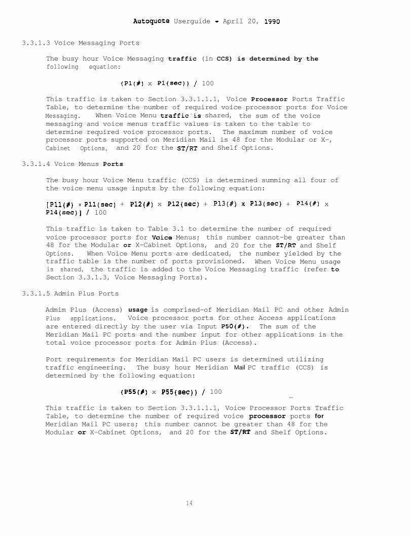
Autoguote Userguide - April 20, 1990
3.3.1.3 Voice Messaging Ports
The busy hour Voice Messaging traffic (in CCS) is determined by thefollowing equation:
(Pl(#) x Pl,(sec)) / 100
This traffic is taken to Section 3.3.1.1.1, Voice Processor Ports TrafficTable, to determine the number of required voice processor ports for VoiceMessaging. When Voice Menu traffic.is shared, the sum of the voicemessaging and voice menus traffic values is taken to the table todetermine required voice processor ports. The maximum number of voiceprocessor ports supported on Meridian Mail is 48 for the Modular or X-,Cabinet Options, and 20 for the ST/RT and Shelf Options.
3.3.1.4 Voice Menus Ports
The busy hour Voice Menu traffic (CCS) is determined summing all four ofthe voice menu usage inputs by the following equation:
[pii x Pll(sec) + P12(#) x PlZ(sec) + P13(#) x Pl3(sec) + Pl4(#) xP14(sec)] / 100
This traffic is taken to Table 3.1 to determine the number of requiredvoice processor ports for Voide Menus; this number cannot-be greater than48 for the Modular or X-Cabinet Options, and 20 for the ST/RT and ShelfOptions. When Voice Menu ports are dedicated, the number yielded by thetraffic table is the number of ports provisioned. When Voice Menu usageis shared, the traffic is added to the Voice Messaging traffic (refer toSection 3.3.1.3, Voice Messaging Ports).
3.3.1.5 Admin Plus Ports
Admim Plus (Access) usage is comprised-of Meridian Mail PC and other AdminPlus applications. Voice processor ports for other Access applicationsare entered directly by the user via Input PSO(#). The sum of theMeridian Mail PC ports and the number input for other applications is thetotal voice processor ports for Admin Plus (Access).
Port requirements for Meridian Mail PC users is determined utilizingtraffic engineering. The busy hour Meridian Mail PC traffic (CCS) isdetermined by the following equation:
(P55(X) x P55(sec)) / 100--
This traffic is taken to Section 3.3.1.1.1, Voice Processor Ports TrafficTable, to determine the number of required voice processor ports forMeridian Mail PC users; this number cannot be greater than 48 for theModular or X-Cabinet Options, and 20 for the ST/RT and Shelf Options.
14
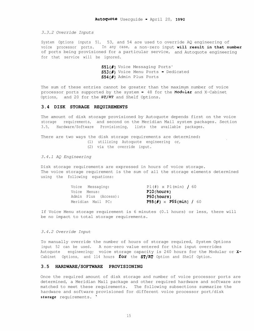
Auto+ote Userguide - April 20, 1990
3.3.2 Override Inputs
System Options inputs 51, 53, and 54 are used to override AQ engineering ofvoice processor ports. In any case, a non-zero input will result in that numberof ports being provisioned for a particular service, and Autoquote engineeringfor that service will be ignored.
SSl(P) Voice Messaging Ports'S53(#) Voice Menu Ports - DedicatedS54(#) Admin Plus Ports
The sum of these entries cannot be greater than the maximum number of voiceprocessor ports supported by the system - 48 for the Modu-lar and X-CabinetOptions, and 20 for the ST/RT and Shelf Options.
3.4 DISK STORAGE REQUIREMENTS
The amount of disk storage provisioned by Autoquote depends first on the voicestorage requirements, and second on the Meridian Mail system packages. Section3.5, Hardware/Software Provisioning, lists the available packages.
There are two ways the disk storage requirements are determined:(1) utilizing Autoquote engineering or,(2) via the override input.
.
3.4.1 AQ Engineering
Disk storage requirements are expressed in hours of voice storage.The voice storage requirement is the sum of all the storage elements determinedusing the following equations:
Voice Messaging: Pl(#) x Pl(min) / 60Voice Menus: PlO(hours)Admin Plus (Access): PSO(hours)Meridian Mail PC: P55(#) x PSS(min) / 60
If Voice Menu storage requirement is 6 minutes (0.1 hours) or less, there willbe no impact to total storage requirements.
3.4.2 Override Input
To manually override the number of hours of storage required, System Optionsinput 52 can be used. A non-zero value entered for this input overridesAutoquote engineering; voice storage capacity is 240 hours for the Modular or X-Cabinet Options, and 114 hours for the ST/RT Option and Shelf Option.
3.5 HARDWARE/SOFTWARE PROVISIONING
Once the required amount of disk storage and number of voice processor ports aredetermined, a Meridian Mail package and other required hardware and software arematched to meet these requirements. The following subsections summarize thehardware and software provisioned for different voice processor port/diskstorage requirements. "
15
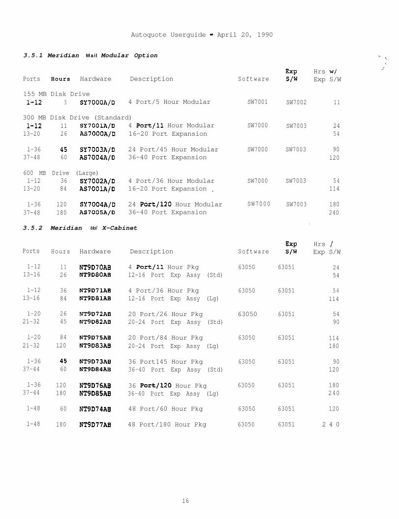
Autoquote Userguide - April 20, 1990
3.5.1 Meridian Mail Modular Option
Ports Hours Hardware Description Software
155 MB Disk Drivel-12 5 SY7OOOA/D 4 Port/5 Hour Modular
300 MB Disk Drive (Standard)l-12 11 SY7001A/D 4 Port/l1 Hour Modular
13-20 26 AS7000A/D 16-20 Port Expansion
l-36 4s SY7003A/D 24 Port/45 Hour Modular37-48 60 AS7004A/D 36-40 Port Expansion
600 MB Drive (Large)l-12 36 SY7002A/D 4 Port/36 Hour Modular
13-20 84 AS7001A/D 16-20 Port Expansion _
1-36 120 SY7004A/D 24 Port/l20 Hour Modular37-48 180 AS7005A/D 36-40 Port Expansion
3.5.2 Meridian Mail X-Cabinet
Ports Hours Hardware Description Software
1-12 11 NT9D7OAB 4 Port/l1 Hour Pkg13-16 26 NT9D80AB 12-16 Port Exp Assy (Std)
Exps/w
63051
Hrs /Exp S/W
63050 2454
l-12 36 NT9D71AB 4 Port/36 Hour Pkg13-16 84 NT9D81AB 12-16 Port Exp Assy (Lg)
63050 63051 54114
l-20 26 NT9D72AB 20 Port/26 Hour Pkg21-32 45 NT9D82AB 20-24 Port Exp Assy (Std)
63050 63051 5490
l-20 84 NT9D75AB 20 Port/84 Hour Pkg21-32 120 NT9D83AB 20-24 Port Exp Assy (Lg)
63050 63051 114180
l-36 45 NT9D73AB 36 Port145 Hour Pkg37-44 60 NT9D84AB 36-40 Port Exp Assy (Std)
63050 63051 90120
l-36 120 NT9D76AB 36 Port/l20 Hour Pkg37-44 180 NT9D85AB 36-40 Port Exp Assy (Lg)
63050 63051 180240
l-48 60 NT9D74AB 48 Port/60 Hour Pkg 63050 63051 120
l-48 180 NT9D77AB 48 Port/l80 Hour Pkg 63050 63051 2 4 0
EXP Hrs w/s/w Exp S/W
SW7001 SW7002 11
SW7000 SW7003 2454
SW7000 SW7003 90120
SW7000 SW7003 54114
SW7000 SW7003 180240
.
. _‘.
I
_”
16
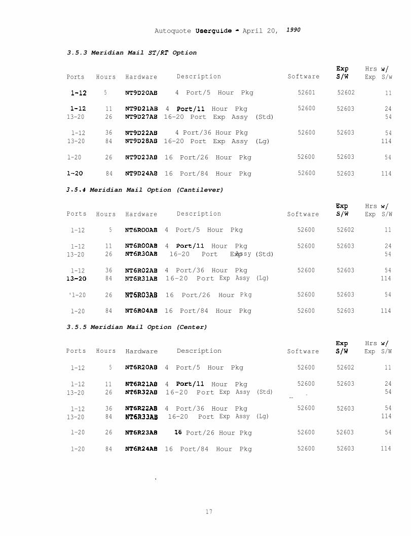
Autoquote Ueerguide - April 20,
3.5.3 Meridian Mail ST/RT Option
Ports Hours Hardware Description
l-12 5 NT9D20AB 4 Port/5 Hour Pkg
l-12 11 NT9DZlAB 4 Port/l1 Hour Pkg13-20 26 NT9D27AB 16-20 Port Exp Assy (Std)
l-12 36 NT9D22AB 4 Port/36 Hour Pkg13-20 84 NT9D28AB 16-20 Port Exp Assy (Lg)
l-20 26 NT9D23AB 16 Port/26 Hour Pkg
l-20 84 NT9D24AB 16 Port/84 Hour Pkg
3.5.4 Meridian Mail Option (Cantilever)
Ports Hours Hardware Description
l-12 5 NT6ROOAB 4 Port/5 Hour Pkg
l-12 11 NT6ROOAB 4 Port/l1 Hour Pkg13-20 26 NT6R30AB 16-20 Port Exp (Std)Assy
l-12 36 NT6R02AB 4 Port/36 Hour Pkg13.-20 84 NT6R31AB 16-20 Port Exp Assy (Lg)
'l-20 26 NT6R03AB 16 Port/26 Hour Pkg
l-20 84 NT6R04AB 16 Port/84 Hour Pkg
3.5.5 Meridian Mail Option (Center)
Ports Hours Hardware Description
l-12 5 NT6R20AB 4 Port/5 Hour Pkg
l-12 11 NT6R21AB 4 Port/l1 Hour Pkg13-20 26 NT6R32AB 16-20 Port Exp Assy (Std)
l-12 36 NT6R22AB 4 Port/36 Hour Pkg13-20 84 NT6R33AB 16-20 Port Exp Assy (Lg)
l-20 26 NT6R23AB 1'6 Port/26 Hour Pkg
l-20 84 NT6R24AB 16 Port/84 Hour Pkg
1990
SoftwareEXPs/w
52601 52602
Hrs w/Exp S/w
11
52600 52603 2454
52600 52603 54114
52600 52603 54
52600 52603 114
Software
52600
BXP Hrs w/s/w Exp S/W
52602 11
52600 52603 2454
52600 52603 54114
52600 52603 54
52600 52603 114
Software
52600
EXPs/w
52602
Hrs w/Exp S/W
11
52600.--
52600
52603 2454
52603
52600 52603
52600 52603
54114
54
114
.
17

Autoquote Userguide - April 20, 1990
.
--
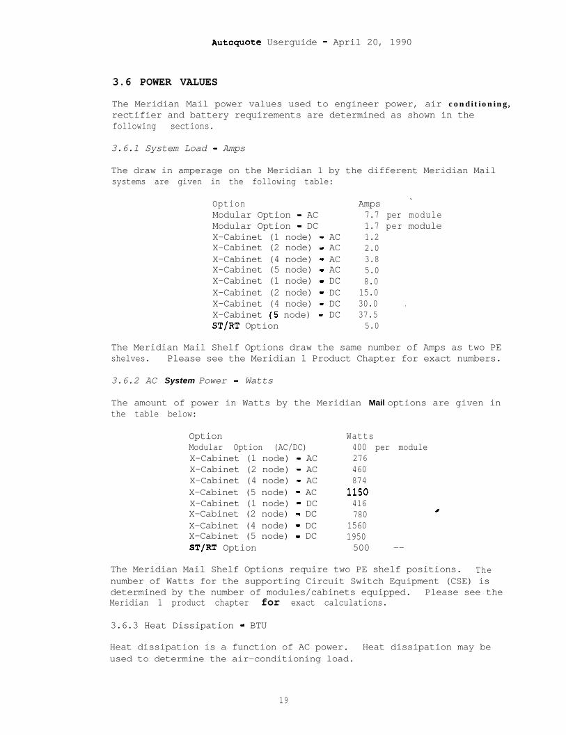
Autoguote Userguide - April 20, 1990
3.6 POWER VALUES
The Meridian Mail power values used to engineer power, air conditioning,rectifier and battery requirements are determined as shown in thefollowing sections.
3.6.1 System Load - Amps
The draw in amperage on the Meridian 1 by the different Meridian Mailsystems are given in the following table:
OptionModular Option - ACModular Option - DCX-Cabinet (1 node) - ACX-Cabinet (2 node) - ACX-Cabinet (4 node) - ACX-Cabinet (5 node) - ACX-Cabinet (1 node) - DCX-Cabinet (2 node) - DCX-Cabinet (4 node) - DCX-Cabinet (5 node) - DCST/RT Option
Amps _7.7 per module1.7 per module1.22.03.85.08.0
15.030.0 .37.55.0
The Meridian Mail Shelf Options draw the same number of Amps as two PEshelves. Please see the Meridian 1 Product Chapter for exact numbers.
3.6.2 AC System Power - Watts
The amount of power in Watts by the Meridian Mail options are given inthe table below:
OptionModular Option (AC/DC)X-Cabinet (1 node) - ACX-Cabinet (2 node) - ACX-Cabinet (4 node) - ACX-Cabinet (5 node) - ACX-Cabinet (1 node) - DCX-Cabinet (2 node) - DCX-Cabinet (4 node) - DCX-Cabinet (5 node) - DCST/RT Option
Watts400 per module276460874
1150416780 /
15601950500 --
The Meridian Mail Shelf Options require two PE shelf positions. Thenumber of Watts for the supporting Circuit Switch Equipment (CSE) isdetermined by the number of modules/cabinets equipped. Please see theMeridian 1 product chapter for exact calculations.
3.6.3 Heat Dissipation - BTU
Heat dissipation is a function of AC power. Heat dissipation may beused to determine the air-conditioning load.
19
AutoquOte Userguide - April 20, 1990
Heat dissipation (BTU/hr) is calculated as follows:
3.415 x System Power(watts)
'One ton of air conditioning is required for every:
12,000 BTUs.500' sq. ft. of equipment room area.
Other factors to consider:
LightsOther equipmentPeople
3.7 MERIDIAN 1 EQUIPMENT PROVISIONING
Interfacing Meridian Mail to the Meridian 1 requires the followingsupporting hardware:
3.7.1 ROM Card
In the following system types, an enhanced ROM card must be addedto support the Command and Status Link (CSL):
SL-1 Type ROM Card---------------------------------------------SL-1MS QPC662SL-1LE QPC573SL-1N QPC571SL-1XL QPC599SL-1XN (w/out memory enhancement) QPC600SL-1XN (w/memory enhancement) QPC601
Any system that does not appear in the list does not require a ROMcard. The proper card type and number are provisioned based onSystem Options input 21 (Model Indicator).
3.7.2 ESDI Card
One Enhanced SD1 (ESDI) port is required for each Meridian Mailsystem interfacing to the Meridian 1. The Meridian Mail ModularOption uses the QPC513F ESDI card. This card allows the Meridian1 CPU a path to talk to the Meridian Mail system via- the Commandand Status Link. The ESDI card will be provisioned by way of theMeridian Mail base hardware packages.
The ESDI card can be housed in any slot in the Meridian 1 that iscapable of supporting a normal Serial Data Interface (SDI) card.
20
. Autoquote Userguide - April 20, 1990
3.7.3 Other Equipment
Two components are required when provisioning the Meridian MailShelf Option in a PE cabinet: a Power Distribution Unit and aCooling Unit. The actual equipment provisioned depends on typemount used, cantilever versus center mount.
Cantilever:
Center:
QBL21 Power Distribution UnitQUDZO Cooling UnitQBLlO Power Distribution UnitQUD5 Cooling Unit
These items are not required if the Meridian Mail Shelf Option isto be housed in the QCA55 SL-1 XT CE Cabinet in the place of anetwork group shelf. Refer to the Meridian 1 Product Chapter formore information on CE shelf and PE shelf housing within SL-1NTand XT systems.
3.8 MERIDIAN 1 IMPACT
Several areas of impact to the circuit switch must be addressed: memory,real time, network cards, ports, and traffic.
3.8.1 Memory
Meridian 1 memory is divided into three segments: Program Store,Protected Data (PDATA) and Unprotected Data (UDATA).
3.8.1.1 Program Store
Impact is due to the required software:
Basic Message Center (SWOOOOA)Auxiliary Processor Link (SW0401A)IVMS Link (SW0402A)Basic ACD Features (SW0201A)Meridian Mail Link (SW0403A)
3.8.1.2 Protected Data/Unprotected Data
The ACD configuration used in Meridian Mail impacts both ProtectedData and Unprotected Data in the same manner-as existing Meridian1 features:
Voice Processor Ports impacts ACD Agent memoryMeridian Mail configuration impacts ACD Queue memory
21
Autoguote Userguide - April 20, 1990
3.8.1.3 Protected Data:
Additional impact for Meridian Mail specific items is given below:
Voice Processor Port (TN) la.50 wordsESDI Port 23.00 wordsCommand and Status Link/Other _ 263.00 words
3.8.1.4 Unprotected Data:
Additional impact for Meridian Mail specific items is given belowin words of memory:
Voice Processor Port (TN) 15.25 wordsCommand and Status Link 367.00 words
3.8.2 Real Time
The number of calls to Meridian Mail per hour is used to calculate realtime impact. The total calls per hour is the sum of the Voice Menucalls and the non-Menu Meridian Mail calls. The number of Voice Menucalls is determined using input usage in the following equation:
-Pll(#) + P12(#) + P13(#) + Pl4(#)
The number of non-Menu calls per hour is the smaller of the followingvalues:
Number of non-Menu ports x 60 or,
Number of registered Voice Messaging users +2 x (Number of Meridian Mail PC Users)
The first equation assumes that one call per non-Menu port per minuteduring the busy hour is used, and the second assumes that one call perregistered Voice Messaging user and two calls per registered MeridianMail PC user during the busy hour.
Using the smaller number ensures the impact of small Meridian Mailsystems is not overestimated.
The actual number of CPU seconds used for Meridian Mail is --calculated as follows:
Number of Meridian Mail Calls per Hour x ART
where, ART = Average Real Time per VM Call.
Average Real Time is typically expressed in milliseconds (ms). ARTdepends on the Meridian 1 system type.c
22
Autoguote Userguide - April 20, 1890
System ART (ms)___e----_-_---------a---LE 1682ST/N 140121 1401XL 364XN 340RT/NT/XT 22151/61/71 221
If the total real time impact of Meridian Mail exceeds 1050 seconds(50% of 2100 CPU seconds capacity), an error message w-ill display andthe quotation process will stop.
3.8.3 Network Cards
Meridian Mail interfaces to the Meridian 1 switching matrix directlythrough a network loop (QPC414).
The number of network loops needed to support the Meridian Mail systemdepends on the number of Meridian mail nodes. Each node can house up to12 voice processor ports. A single dedicated network loop can supportup to 2 Meridian Mail nodes, and two dedicated network loops can supportup to 5 nodes.
The Meridian Mail Modular Option packages contain network cards; 1QPC414B for each of the 4 port base packages and 2 QPC414B's for the 24port base packages.
Refer to the Meridian 1 Product Chapter for more information on CommonEquipment cards and network loops.
3.8.4 Traffic
Autoquote assumes 28 CCS will be added to the total system busy hourtraffic for each voice processor port provisioned. For most systems,this traffic will be added to total P.01 Grade of Service traffic. ForMeridian 1 systems provisioned as totally non-blocking, the number ofvoice processor ports will be added to the total non-blocking ports. Ineither case, network provisioning may or may not be impacted by theMeridian Mail requirements depending on the size of the Meridian Mailsystem and the amount of traffic on the switch.
Refer to the Meridian 1 Product Chapter for more infurmation on networkloops and traffic engineering.
3.8.5 Meridian Mail Integration Considerations
Differences of integration with the Meridian 1 between the variousMeridian Mail Options are covered in the following subsections.
23
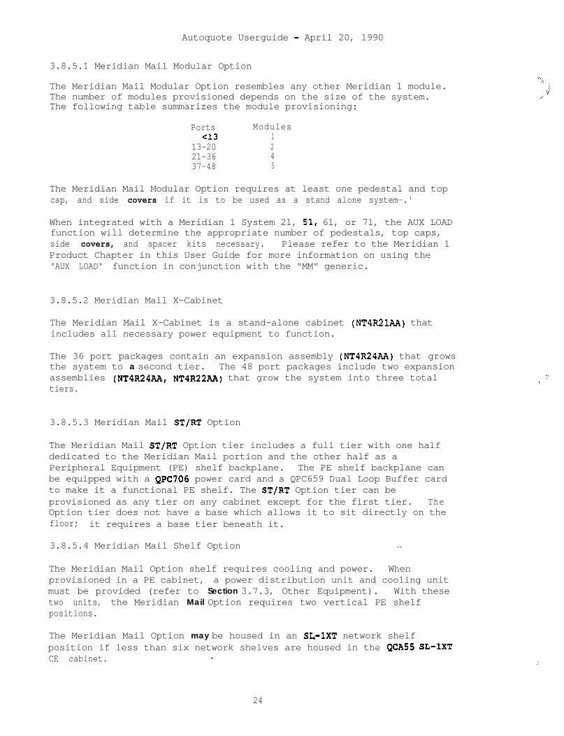
Autoquote Userguide - April 20, 1990
3.8.5.1 Meridian Mail Modular Option
The Meridian Mail Modular Option resembles any other Meridian 1 module.The number of modules provisioned depends on the size of the system.The following table summarizes the module provisioning:
Ports ModulesCl3 1
13-20 221-36 437-48 5
The Meridian Mail Modular Option requires at least one pedestal and topcap, and side covers if it is to be used as a stand alone system-.‘
When integrated with a Meridian 1 System 21, 51, 61, or 71, the AUX LOADfunction will determine the appropriate number of pedestals, top caps,side covers, and spacer kits necessary. Please refer to the Meridian 1Product Chapter in this User Guide for more information on using the"AUX LOAD" function in conjunction with the "MM" generic.
3.8.5.2 Meridian Mail X-Cabinet
The Meridian Mail X-Cabinet is a stand-alone cabinet (NT4R21AA) thatincludes all necessary power equipment to function.
The 36 port packages contain an expansion assembly (NT4R24AA) that growsthe system to a second tier. The 48 port packages include two expansionassemblies (NT4R24AA, NT4R22AA) that grow the system into three totaltiers.
3.8.5.3 Meridian Mail ST/RT Option
The Meridian Mail ST/RT Option tier includes a full tier with one halfdedicated to the Meridian Mail portion and the other half as aPeripheral Equipment (PE) shelf backplane. The PE shelf backplane canbe equipped with a QPC706 power card and a QPC659 Dual Loop Buffer cardto make it a functional PE shelf. The ST/RT Option tier can beprovisioned as any tier on any cabinet except for the first tier. TheOption tier does not have a base which allows it to sit directly on thefloor; it requires a base tier beneath it.
3.8.5.4 Meridian Mail Shelf Option --
The Meridian Mail Option shelf requires cooling and power. Whenprovisioned in a PE cabinet, a power distribution unit and cooling unitmust be provided (refer to Section 3.7.3, Other Equipment). With thesetwo units, the Meridian Mail Option requires two vertical PE shelfpositions.
The Meridian Mail Option may be housed in an SL-1XT network shelfposition if less than six network shelves are housed in the QCA55 SL-1XTCE cabinet. *.
-\
j
.’
2(.
,’
24

Autoquote Ueerguide - April 20, 1990
4. REPORTS
This section provides information on most reports available with theMeridian Mail quotation model. An explanation and example of eachreport is included.
l- Price Summary4- Engineering Summary6- Input Listing9 - Equipment List17 - Circuit Switch Impact21 - Power Summary
A sample of report 15 Discount Summary will not appear in the UserGuide; this report subtotals price by discount categories. Onlyauthorized users have access to any discounting information.
The header report (Report 9999) will print out automatically whenreports are requested; this report may also be requested-like any otherreport.
Within each subsection there are explanations of the contents of thereport being discussed.
The mechanics of using Autoquote are not included in this productchapter. Refer to the Introduction and Overview chapter for detailedinformation on how to use the Autoquote system.
25
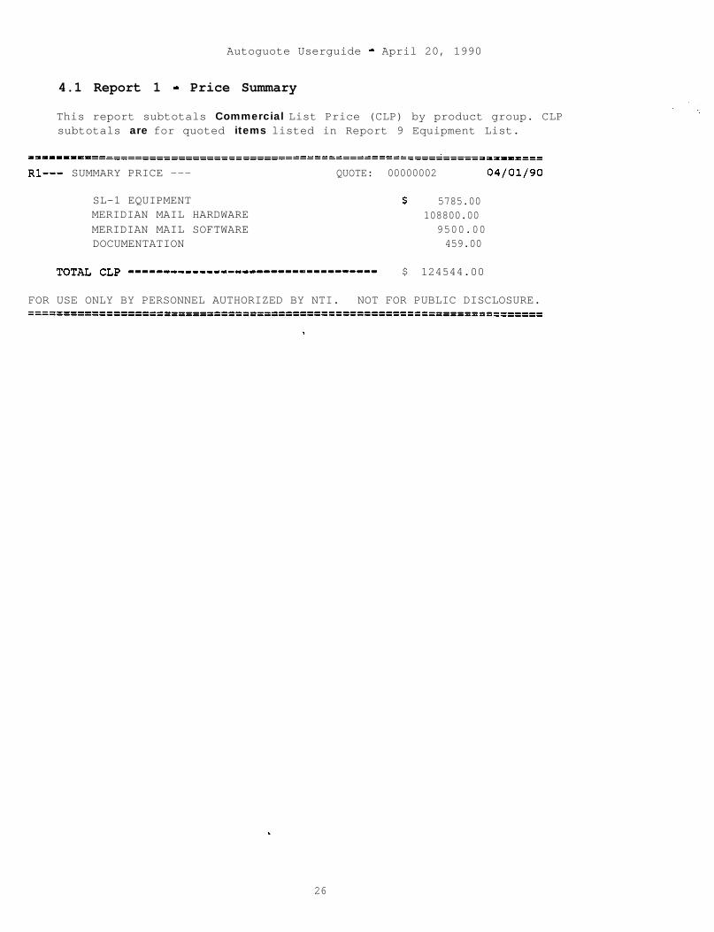
Autoguote Userguide - April 20, 1990
4.1 Report 1 - Price Summary
This report subtotals Commercial List Price (CLP) by product group. CLPsubtotals are for quoted items listed in Report 9 Equipment List.
=========================================================~==============
Rl--- SUMMARY PRICE --- QUOTE: 00000002 04/01/90
SL-1 EQUIPMENT $ 5785.00MERIDIAN MAIL HARDWARE 108800.00MERIDIAN MAIL SOFTWARE 9500.00DOCUMENTATION 459.00
TOTAL CLP --------------------____o__________ $ 124544.00
FOR USE ONLY BY PERSONNEL AUTHORIZED BY NTI. NOT FOR PUBLIC DISCLOSURE.============================o'===='=========================================
.
26
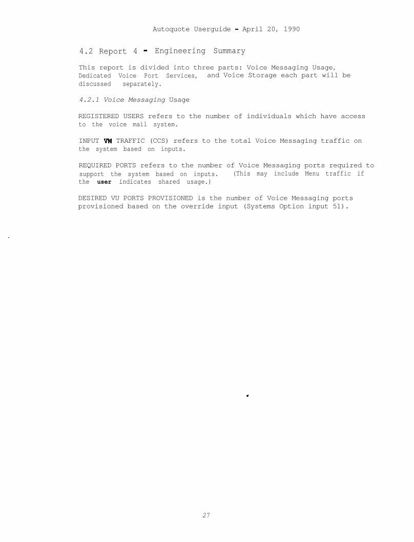
Autoquote Userguide - April 20, 1990
4.2 Report 4 - Engineering Summary
This report is divided into three parts: Voice Messaging Usage,Dedicated Voice Port Services, and Voice Storage each part will bediscussed separately.
4.2.1 Voice Messaging Usage
REGISTERED USERS refers to the number of individuals which have accessto the voice mail system.
INPUT VM TRAFFIC (CCS) refers to the total Voice Messaging traffic onthe system based on inputs.
REQUIRED PORTS refers to the number of Voice Messaging ports required tosupport the system based on inputs. (This may include Menu traffic ifthe user indicates shared usage.)
DESIRED VU PORTS PROVISIONED is the number of Voice Messaging portsprovisioned based on the override input (Systems Option input 51).
27
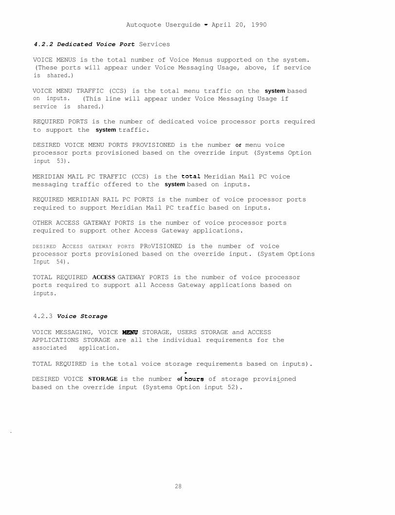
Autoquote Userguide - April 20, 1990
4.2.2 Dedicated Voice Port Services
VOICE MENUS is the total number of Voice Menus supported on the system.(These ports will appear under Voice Messaging Usage, above, if serviceis shared.)
VOICE MENU TRAFFIC (CCS) is the total menu traffic on the system basedon inputs. (This line will appear under Voice Messaging Usage ifservice is shared.)
REQUIRED PORTS is the number of dedicated voice processor ports requiredto support the system traffic.
DESIRED VOICE MENU PORTS PROVISIONED is the number Of menu voiceprocessor ports provisioned based on the override input (Systems Optioninput 53).
MERIDIAN MAIL PC TRAFFIC (CCS) is the total Meridian Mail PC voicemessaging traffic offered to the system based on inputs.
REQUIRED MERIDIAN RAIL PC PORTS is the number of voice processor portsrequired to support Meridian Mail PC traffic based on inputs.
OTHER ACCESS GATEWAY PORTS is the number of voice processor portsrequired to support other Access Gateway applications.
DESIRED ACCESS GATEWAY PORTS PROVISIONED is the number of voiceprocessor ports provisioned based on the override input. (System OptionsInput 54).
TOTAL REQUIRED ACCESS GATEWAY PORTS is the number of voice processorports required to support all Access Gateway applications based oninputs.
4.2.3 Voice Storage
VOICE MESSAGING, VOICE MRNU STORAGE, USERS STORAGE and ACCESSAPPLICATIONS STORAGE are all the individual requirements for theassociated application.
TOTAL REQUIRED is the total voice storage requirements based on inputs).
DESIRED VOICE STORAGE is the number of iours of storage provisionedbased on the override input (Systems Option input 52).
--
28
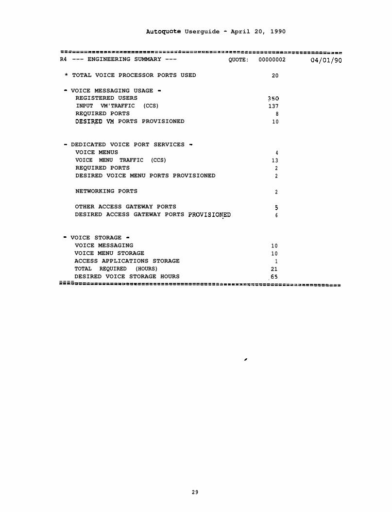
AutOquOte Userguide - April 20, 1990
----------==p=---------=========================================-------=R4 --- ENGINEERING SUMMARY --- QUOTE: 00000002 04/01/90
* TOTAL VOICE PROCESSOR PORTS USED 20
- VOICE MESSAGING USAGE -REGISTERED USERS 250INPUT VM'TRAFFIC (CCS) 137REQUIRED PORTS 8DESIRED VM PORTS PROVISIONED 10
- DEDICATED VOICE PORT SERVICES -VOICE MENUS 4VOICE MENU TRAFFIC (CCS) 13REQUIRED PORTS 2DESIRED VOICE MENU PORTS PROVISIONED 2
NETWORKING PORTS 2
OTHER ACCESS GATEWAY PORTS 5DESIRED ACCESS GATEWAY PORTS PROVISIONED 6
- VOICE STORAGE -VOICE MESSAGING 10VOICE MENU STORAGE 10ACCESS APPLICATIONS STORAGE 1TOTAL REQUIRED (HOURS) 21DESIRED VOICE STORAGE HOURS .65--------i==t"====PPXDf='=I===========I==========================================
c
29
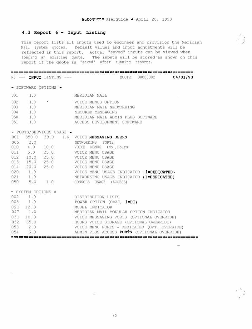
AutoquOte Userguide - April 20, 1990
4.3 Report 6 - Input Listing
This report lists all inputs used to engineer and provision the MeridianMail system quoted. Default values and input adjustments will bereflected in this report. Actual "saved" inputs can be viewed whenloading an existing quote. The inputs will be stored'as shown on thisreport if the quote is "saved" after running reports.
==---------------=-----===---------5======================================
R6 --- 1,NPUT LISTING --- QUOTE: 00000002 04/01/90
- SOFTWARE OPTIONS -
001 1.0 MERIDIAN MAIL .002 1.0 - VOICE MENUS OPTION003 1.0 MERIDIAN MAIL NETWORKING004 1.0 SECURED MESSAGING050 1.0 MERIDIAN MAIL ADMIN PLUS SOFTWARE051 1.0 ACCESS DEVELOPMENT SOFTWARE
- PORTS/SERVICES USAGE -001 350.0 39.0 1.6 VOICE MESSAGING.USERS005 2.0 NETWORKING PORTS010 4.0 10.0 VOICE MENUS (No.,Hours)011 5.0 25.0 VOICE MENU USAGE012 10.0 25.0 VOICE MENU USAGE013 15.0 25.0 VOICE MENU USAGE014 20.0 25.0 VOICE MENU USAGE020 1.0 VOICE MENU USAGE INDICATOR (l=DEDICATED)021 1.0 NETWORKING USAGE INDICATOR (l=DEDICATED)050 5.0 1.0 CONSOLE USAGE (ACCESS)
- SYSTEM OPTIONS -002 1.0 DISTRIBUTION LISTS005 1.0 POWER OPTION (O=AC, l=DC)021 12.0 MODEL INDICATOR047 1.0 MERIDIAN MAIL MODULAR OPTION INDICATOR051 10.0 VOICE MESSAGING PORTS (OPTIONAL OVERRIDE)052 65.0 HOURS VOICE STORAGE (OPTIONAL OVERRIDE)053 2.0 VOICE MENU PORTS - DEDICATED (OPT. OVERRIDE)054 6.0 ADMIN PLUS ACCESS PORfS (OPTIONAL OVERRIDE)=============================fl==================================
--
*,
30
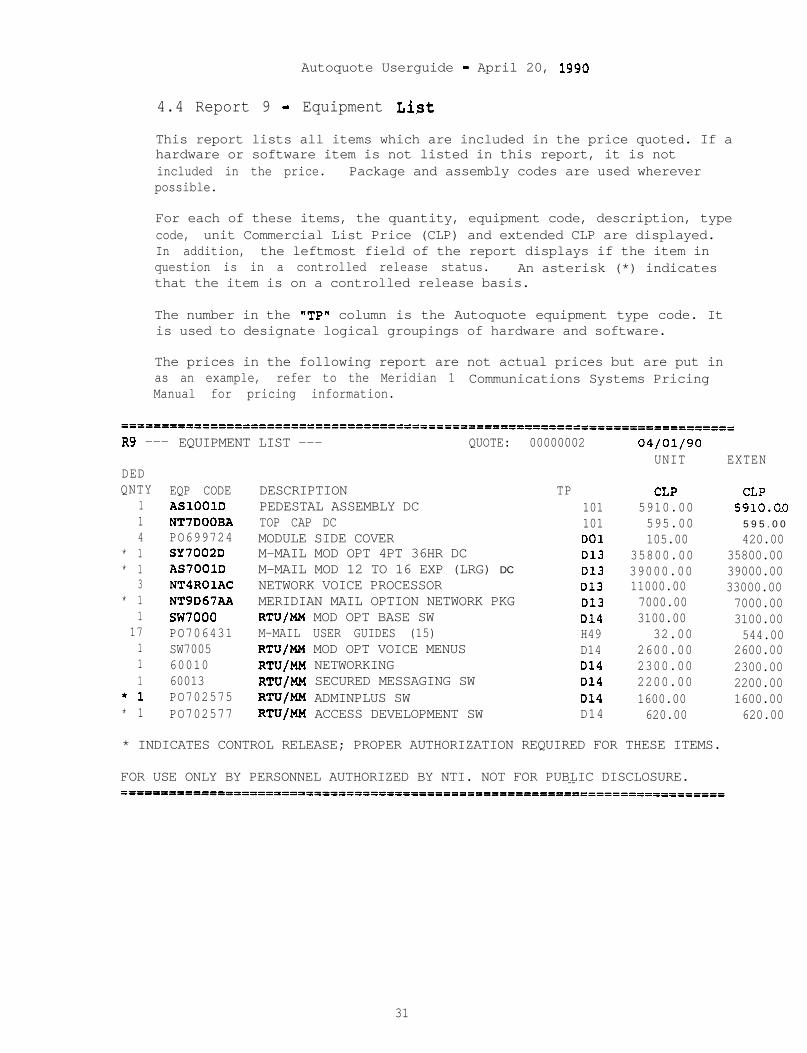
Autoquote Userguide - April 20, 1990
4.4 Report 9 - Equipment List
This report lists all items which are included in the price quoted. If ahardware or software item is not listed in this report, it is notincluded in the price. Package and assembly codes are used whereverpossible.
For each of these items, the quantity, equipment code, description, typecode, unit Commercial List Price (CLP) and extended CLP are displayed.In addition, the leftmost field of the report displays if the item inquestion is in a controlled release status. An asterisk (*) indicatesthat the item is on a controlled release basis.
The number in the "TP" column is the Autoquote equipment type code. Itis used to designate logical groupings of hardware and software.
The prices in the following report are not actual prices but are put inas an example, refer to the Meridian 1 Communications Systems PricingManual for pricing information.
R9 --- EQUIPMENT LIST --- QUOTE: 00000002
DEDQNTY
114
* 1* 1
3* 1
117111
*1* 1
EQP CODEASlOOlDNT7DOOBAPO699724SY7002DAS7001DNT4ROlACNT9D67AAsw7000PO706431SW70056001060013PO702575PO702577
DESCRIPTIONPEDESTAL ASSEMBLY DCTOP CAP DCMODULE SIDE COVERM-MAIL MOD OPT 4PT 36HR DCM-MAIL MOD 12 TO 16 EXP (LRG) DC
NETWORK VOICE PROCESSORMERIDIAN MAIL OPTION NETWORK PKGRTU/MM MOD OPT BASE SWM-MAIL USER GUIDES (15)RTU/MM MOD OPT VOICE MENUSRTU/MM NETWORKINGRTU/MM SECURED MESSAGING SWRTU/MM ADMINPLUS SWRTU/MM ACCESS DEVELOPMENT SW
TP CLP CLP101 5910.00 5910.0.0
101 595.00 5 9 5 . 0 0DO1 105.00 420.00D13 35800.00 35800.00D13 39000.00 39000.00D13 11000.00 33000.00D13 7000.00 7000.00D14 3100.00 3100.00H49 32.00 544.00D14 2600.00 2600.00D14 2300.00 2300.00D14 2200.00 2200.00D14 1600.00 1600.00D14 620.00 620.00
04/01/90UNIT EXTEN
* INDICATES CONTROL RELEASE; PROPER AUTHORIZATION REQUIRED FOR THESE ITEMS.
FOR USE ONLY BY PERSONNEL AUTHORIZED BY NTI. NOT FOR PUBLIC DISCLOSURE.--
31
Autoquote Userguide - April 20, 1990
4.5 Report 17 - Circuit Switch Impact
This report details the items which will be affected on the Meridian 1circuit switch supporting the Meridian Mail system.
Memory is the first area addressed in the report. The U-data, P-data,and Program Store values listed reflect the addition of all requiredsoftware options plus the ACD configuration and TN requirements. If theexisting Meridian 1 system is already equipped with one or more of thesefeatures, the memory requirements for adding Meridian Mail will be less.
The required software options to support Meridian Mail are listed next.Note that Auxiliary Processor Link software is applicable to X11 Release10 or later.
REAL TIME capacity is also affected by the Meridian Mail integration.The impact is listed as TOTAL SECONDS and PERCENT of capacity; theparameters used to calculate these values are also included.
OTHER INFORMATION lists the number of Serial Data Interface (SDI) slotsrequired to house the ESDI card.
VOICE MESSAGING TRAFFIC (CCS) is total traffic added to the Meridian 1because of Meridian Mail system.
32
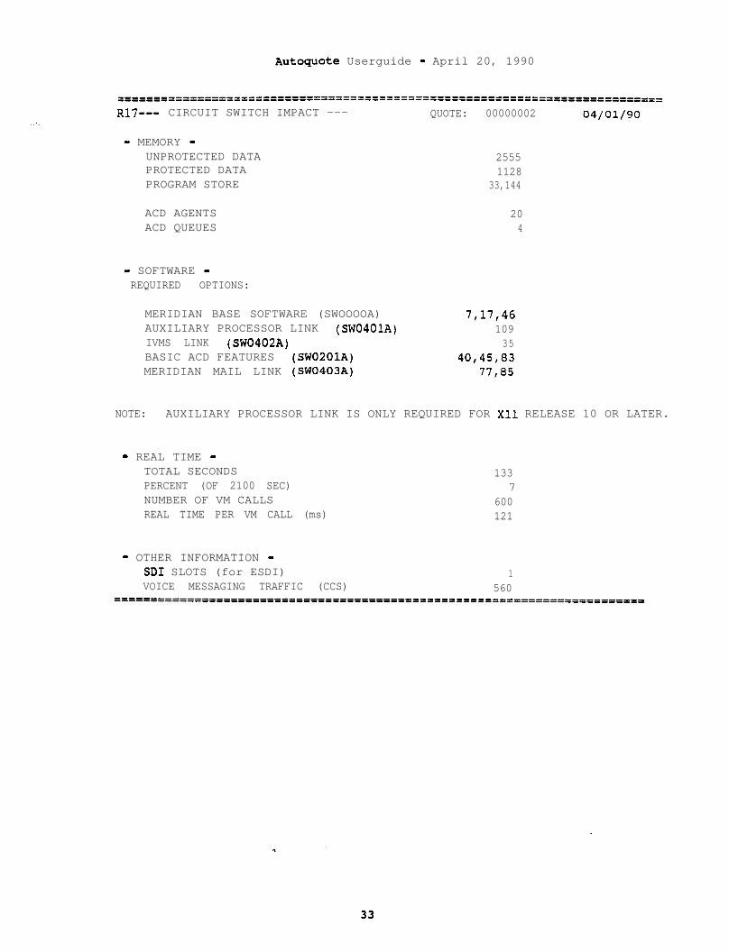
Autoguote Userguide - April 20, 1990
==-----------------========================================================R17--- CIRCUIT SWITCH IMPACT --- QUOTE: 00000002 04/01/90
- MEMORY -UNPROTECTED DATAPROTECTED DATAPROGRAM STORE
25551128
33,144
ACD AGENTS 20ACD QUEUES 4
- SOFTWARE -REQUIRED OPTIONS:
MERIDIAN BASE SOFTWARE (SWOOOOA) 7,17,46AUXILIARY PROCESSOR LINK (SW0401A) 109IVMS LINK (SW0402A) 35BASIC ACD FEATURES (SW0201A) 40,45,83MERIDIAN MAIL LINK (SW0403A) 77,85
NOTE: AUXILIARY PROCESSOR LINK IS ONLY REQUIRED FOR Xl1 RELEASE 10 OR LATER.
- REAL TIME -TOTAL SECONDS 133PERCENT (OF 2100 SEC) 7NUMBER OF VM CALLS 600REAL TIME PER VM CALL (ms) 121
- OTHER INFORMATION -SD1 SLOTS (for ESDI) 1VOICE MESSAGING TRAFFIC (CCS) 560
====================='oI='I====================================================

Autoquote Userguide - April 20, 1990
4.6 Report 21 - Power Summary
This report contains information concerning several aspects of power.AC CUBRBNT (AMPS) is the current load of the system.AC POWER (WATTS) is the total utility power required for the system.HEAT OUTPUT (BTU's/hr) is the heat output of the system.
==----------=-------------------===-IE=I===================================
R21--- POWER SUMMARY --- QUOTE: 00000002 04/01/90
CURRENT (AMPS) 16.0
POWER (WATTS) 800 .HEAT OUTPUT (BTU/hr) 2732
===========================================================================
\
V ,
34
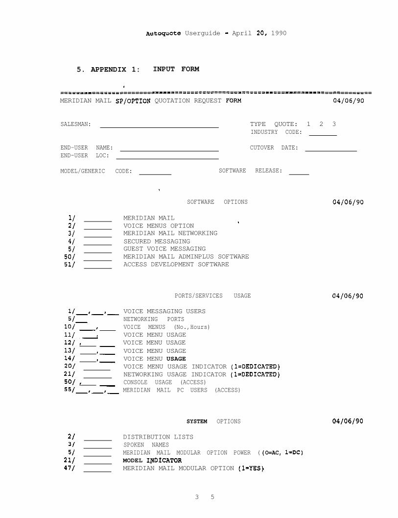
Autoguote Userguide - April 20, 1990
5. APPENDIX 1: INPUT FORM
.
====PI=I========DP=fDX========-f=================================--------------====
MERIDIAN MAIL SP/OPTION QUOTATION REQUEST FORM 04/06/90
SALESMAN: TYPE QUOTE: 1 2 3INDUSTRY CODE:
END-USER NAME: CUTOVER DATE:END-USER LOC:
MODEL/GENERIC CODE: SOFTWARE RELEASE:
.
SOFTWARE OPTIONS
1/ MERIDIAN MAIL2/ VOICE MENUS OPTION
.
3/ MERIDIAN MAIL NETWORKING4/ SECURED MESSAGING5/ GUEST VOICE MESSAGING
SO/ MERIDIAN MAIL ADMINPLUS SOFTWARE51/ ACCESS DEVELOPMENT SOFTWARE
PORTS/SERVICES USAGE
1/-'-I- VOICE MESSAGING USERS51 NETWORKING PORTSlo/--, VOICE MENUS (No.,Hours)11/ I VOICE MENU USAGE12/ I- VOICE MENU USAGE13/ I- VOICE MENU USAGE14/ t- VOICE MENU USAGE20/ - VOICE MENU USAGE INDICATOR (l=DEDICATED)21/ NETWORKING USAGE INDICATOR (l=DEDICATED)5G/ I55/ -
CONSOLE USAGE (ACCESS)-I-'- MERIDIAN MAIL PC USERS (ACCESS)
SYSTEM OPTIONS
21 DISTRIBUTION LISTS3/ SPOKEN NAMES51 MERIDIAN MAIL MODULAR OPTION POWER (
21/ MODEL INDICATQR47/ MERIDIAN MAIL MODULAR OPTION (IrYES)
O=AC, l=DC)
04/06/90
04/06/90
04/06/90
3 5

Autoguote Userguide - April 20, 1990
4S/4915U/51152153/541
MERIDIAN MAIL X INDICATOR (l=MERIDIAN MAIL X)OPTION INDICATOR (O=MM-S,l=ST/RT OPTION,2=CANT,3=CENTSYSTEM PURCHASE INDICATOR (l=NO)NUMBER OF VOICE MESSAGING PORTS (OPTIONAL OVERRIDE)
. HOURS VOICE STORAGE (OPTIONAL OVERRIDE)VOICE MENU PORTS - DEDICATED (OPTIONAL OVERRIDE)CONSOLE ACCESS PORTS (OPTIONAL OVERRIDE) ~
‘.
.
36
Meridian 1
AUTOQUOTE USER GUIDE

--
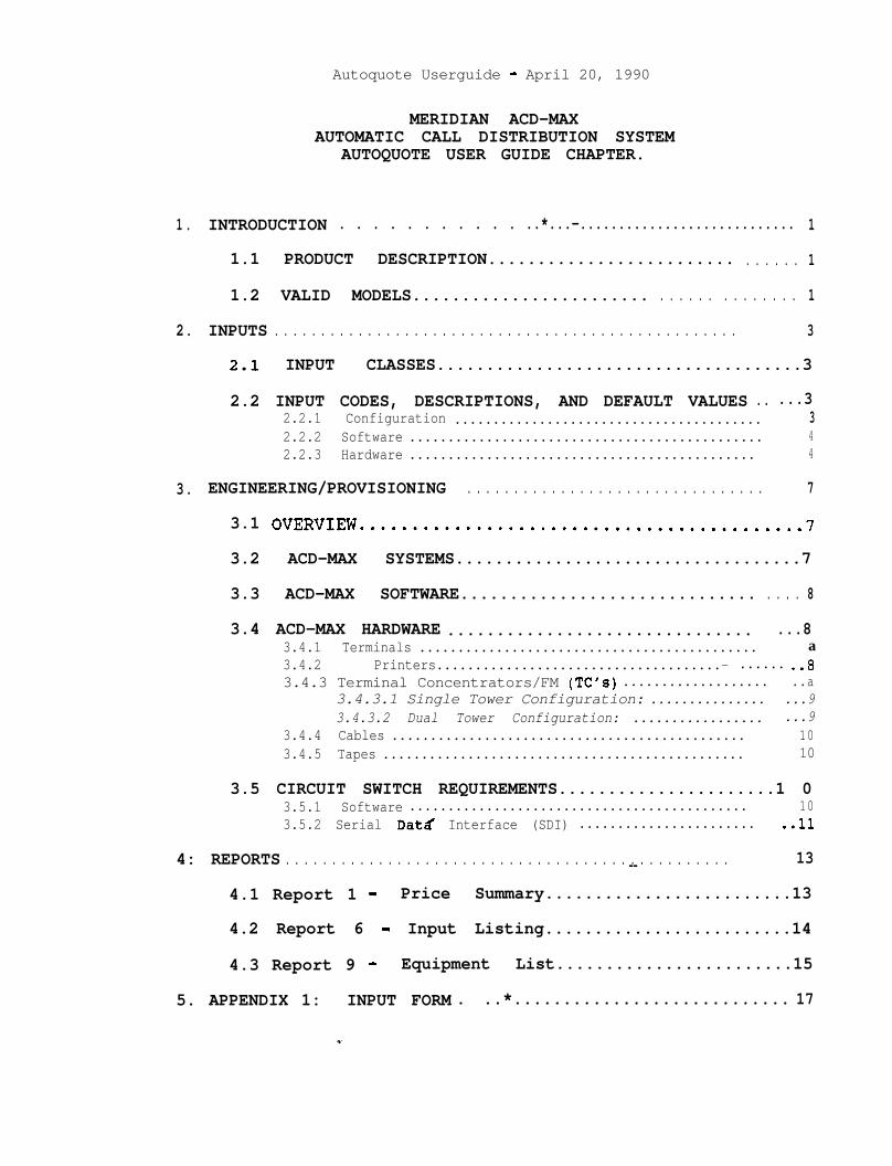
Autoquote Userguide - April 20, 1990
MERIDIAN ACD-MAXAUTOMATIC CALL DISTRIBUTION SYSTEM
AUTOQUOTE USER GUIDE CHAPTER.
1. INTRODUCTION . . . . . . . . . . . ..*...-............................ 1
1.1 PRODUCT DESCRIPTION......................... . . . . . . 1
1.2 VALID MODELS........................ . . . . . . . . . . . . . . 1
2. INPUTS . . . . . . . . . . . . . . . . . . . . . . . . . . . . . . . . . . . . . . . . . . . . . . . . . . 3
2.1 INPUT CLASSES.....................................3
2.2 INPUT CODES, DESCRIPTIONS, AND DEFAULT VALUES .. ...32.2.1 Configuration ........................................ 32.2.2 Software .............................................. 42.2.3 Hardware ............................................. 4
3. ENGINEERING/PROVISIONING . . . . . . . . . . . . . . . . . . . . . . . . . . . . . . . . 7
3.1 OVERVIEW..........................................7
3.2 ACD-MAX SYSTEMS...................................7
3.3 ACD-MAX SOFTWARE.............................. . . . . 8
3.4 ACD-MAX HARDWARE ............................... ...83.4.1 Terminals ............................................ a3.4.2 Printers.....................................- ...... ..a3.4.3 Terminal Concentrators/FM (TC's) ................... ..a
3.4.3.1 Single Tower Configuration: ............... ...93.4.3.2 Dual Tower Configuration: ................. ...9
3.4.4 Cables .............................................. 103.4.5 Tapes ............................................... 10
3.5 CIRCUIT SWITCH REQUIREMENTS......................1 03.5.1 Software ............................................ 103.5.2 Serial Datd Interface (SDI) ....................... ..ll
4: REPORTS . . . . . . . . . . . . . . . . . . . . . . . . . . . . . . . . . . . . . . . . . . . . . . . . 13--4.1 Report 1 - Price Summary.........................13
4.2 Report 6 - Input Listing.........................14
4.3 Report 9 - Equipment List........................15
5. APPENDIX 1: INPUT FORM . ..*............................ 17

Autoquote Userguide - April 20, 1990
. .
.
: .;
AutOquOte Userguide - April 20, 1990
1. INTRODUCTION
This chapter of the Meridian 1 Communication Systems Autoquote UserGuide provides information on quoting the ACD-MAX. It includes thefollowing sections:
Section 1: IntroductionSection 2: InputsSection 3: Engineering/ProvisioningSection 4: Reports
The mechanics of using Autoquote are not included in this productchapter. Refer to the Introduction and Overview chapter for detailedinformation on how to use the Autoquote System.
1.1 PRODUCT DESCRIPTION
ACD-MAX is a PC based stand alone Automatic Call Distribution (ACD)system providing call report capabilities to the smaller user who
requires sophisticated reporting. ACD-MAX provides real time displayswith exception highlighting, ad hoc reports and scheduled historicalreports.
1.2 VALID MODELS
There are two valid Meridian Mail Autoquote models.
ModelGeneric Code Release
ACD-MAXOn-line Input Form
MAX <RETURN>MAXF <RETURN>
Neither of the models has an associated release; i.e. enter RETURN atthe release prompt.
1

Autoquote Userguide - April 20, 1990
Autoguote Userguide - April 20, 1990
2 . INPUTS
This section covers all inputs associated with the ACD-MAX generic. Thefollowing subsections are contained wi-thin this section:
Input ClassesInput Codes, Descriptions, And Default Values
2.1 INPUT CLASSES
ACD-MAX inputs are organized into the three following input classes:
ACD-MAX Configuration [ClACD-MAX Software ISIACD-MAX Hardware [HI
The letter designation is used to select the input class from the inputmenu.
2.2 INPUT CODES, DESCRIPTIONS, AND DEFAULT VALUES
The following section contains information on each ACD-MAX input.Descriptions and defaults are included where appropriate.
2.2.1 Configuration
The following inputs are used to determine the appropriate ACD-MAXsystem and to determine traffic and memory values.
1 Number of ACD Agents
Enter the number agent positions on the ACD-MAX; the maximumis 500 agents. .
2 Number of Supervisory Terminals
Enter the total number of Supervisory Terminals desired onthe system. These will include the HP770/22 Terminals andany PC's that will be used as Color-Graphics Terminals. Oneterminal is required, and a maximum of 32 terminals issupported.
3 Number of ACD Queues
Enter the Number of ACD Queues to be supported on the ACD-MAX system. A maximum of 30 queues.can be supported.
Autoguote Userguide - April 20, 1990
4 Calls per Hour
Enter the maximum number of calls per hour to be handled bythe ACD-MAX system. A maximum of 10000 calls per hour aresupported on a Dual Tower system (3000 on a Single Tower).
5 Dual Tower Required
Enter a one (1) to ignore Autoquote calculations on systemsizing. A one (1) will automatically provision a dual towersystem.
2.2.2 Software
Software inputs are used to provision optional software that can be usedto enhance the ACD-MAX system.
1 Configuration Control
Enter a one (1) if Configuration Control software isdesired. Enter a zero (0) to remove the software.
2 Custom Calculator
Enter a one (1) if Custom Calculator software is desired.Enter a zero (0) to remove the software.
3 Networked ACD
Enter a one (1) if Networked ACD software is desired. Entera zero (0) to remove the software.
2.2.3 Hardware
The following inputs are used to provision peripheral hardware for theACD-MAX system.
1 HP770122 Amber Terminal.
Enter the number of Amber Terminals desired.
--2 HP RuggedWriter Printer
Enter the number of RuggedWriter Printers desired.
3 HP PaintJet Printer
Enter the number of PaintJet Printers desired.
4 HP DeskJet Printer
Enter the number of DeskJet Printers desired.
4
Autoquote Ueerguide - April 20, 1990
5 BP LaserJet Printer
Enter the number of LaserJet Printers desired.
6 Supervisor Color Graphic Cables
Enter the number of Superv-isor Color Graphic Terminals willbe used on the system. This input is'used to provisioncables for the Color Graphic PC's.
7 Additional 3M Backup Tapes
Enter the number of additional tapes desired for backup ofthe ACD-MAX system.

Autoquote Userguide - April 20, 1990
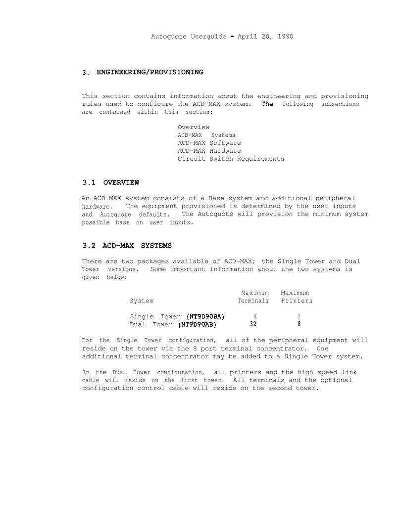
Autoguote Userguide - April 20, 1990
3. ENGINEERING/PROVISIONING
This section contains information about the engineering and provisioningrules used to configure the ACD-MAX system. The. following subsectionsare contained within this section:
OverviewACD-MAX SystemsACD-MAX SoftwareACD-MAX HardwareCircuit Switch Requirements
3.1 OVERVIEW
An ACD-MAX system consists of a Base system and additional peripheralhardware. The equipment provisioned is determined by the user inputsand Autoquote defaults. The Autoguote will provision the minimum systempossible base on user inputs.
3.2 ACD-MAX SYSTEMS
There are two packages available of ACD-MAX; the Single Tower and DualTower versions. Some important information about the two systems isgiven below:
SystemMaximum Maximum
Terminals Printers
Single Tower (NT9D90BA) 8 2Dual Tower (NT9D90AB) 32 8
For the Single Tower configuration, all of the peripheral equipment willreside on the tower via the 8 port terminal concentrator. Oneadditional terminal concentrator may be added to a Single Tower system.
In the Dual Tower configuration, all printers and the high speed linkcable will reside on the first tower. All terminals and the optionalconfiguration control cable will reside on the second tower.
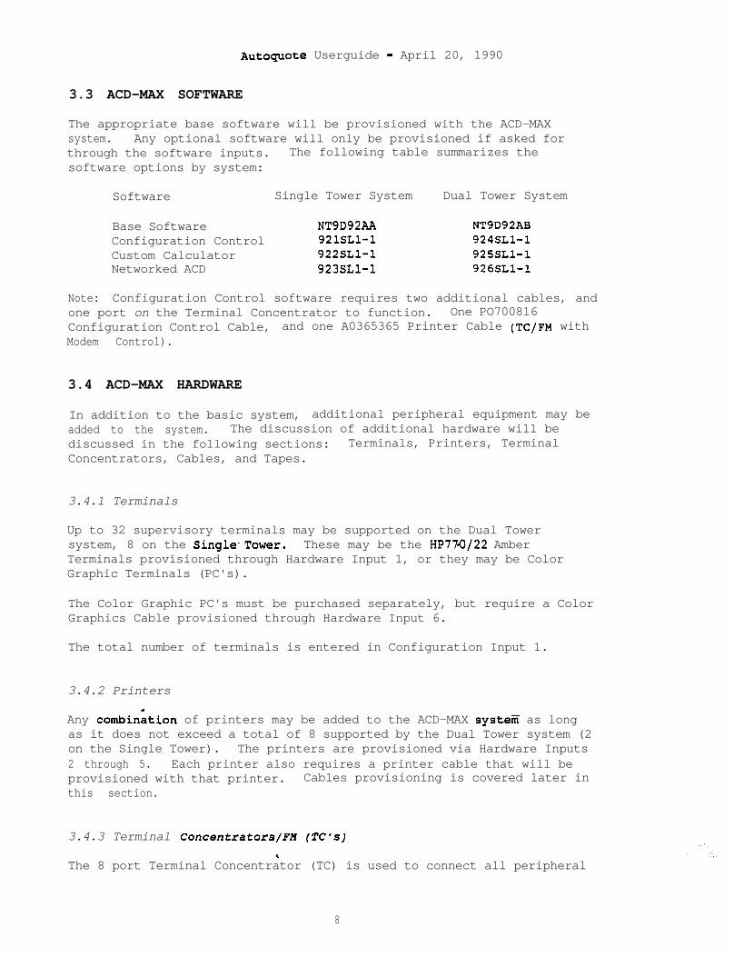
Autoquote Userguide - April 20, 1990
3.3 ACD-MAX SOFTWARE
The appropriate base software will be provisioned with the ACD-MAXsystem. Any optional software will only be provisioned if asked forthrough the software inputs. The following table summarizes thesoftware options by system:
Software Single Tower System Dual Tower System
Base SoftwareConfiguration ControlCustom CalculatorNetworked ACD
NT9D92AA NT9D92AB921SLl-1 924SLl-1922SLl-1 925SLl-1923SLl-1 926SLl-1
Note: Configuration Control software requires two additional cables, andone port on the Terminal Concentrator to function. One PO700816Configuration Control Cable, and one A0365365 Printer Cable (TC/FM withModem Control).
3.4 ACD-MAX HARDWARE
In addition to the basic system, additional peripheral equipment may beadded to the system. The discussion of additional hardware will bediscussed in the following sections: Terminals, Printers, TerminalConcentrators, Cables, and Tapes.
3.4.1 Terminals
Up to 32 supervisory terminals may be supported on the Dual Towersystem, 8 on the Single'Tower. These may be the HP770122 AmberTerminals provisioned through Hardware Input 1, or they may be ColorGraphic Terminals (PC's).
The Color Graphic PC's must be purchased separately, but require a ColorGraphics Cable provisioned through Hardware Input 6.
The total number of terminals is entered in Configuration Input 1.
3.4.2 Printers
Any combinition of printers may be added to the ACD-MAX system as longas it does not exceed a total of 8 supported by the Dual Tower system (2on the Single Tower). The printers are provisioned via Hardware Inputs2 through 5. Each printer also requires a printer cable that will beprovisioned with that printer. Cables provisioning is covered later inthis section.
3.4.3 Terminal Concentrators/FH (TC's)
The 8 port Terminal Concentrator (TC) is used to connect all peripheral
8

Autoquote Userguide - April 20, 1880
devices to the ACD-MAX system. The Single Tower provides one, and theDual Tower provides two with the system, one for each tower. AllTerminal Concentrators provisioned will have Modem Controlfunctionality. (A0368534)
The following equations are used to determine the number of TC's thatwill be provisioned. In the equations-below, if Configuration Controlid equipped then the value is equal to one (1), if not equipped, then itis equal to zero (0). HSL Cable refers to the High. Speed Link Cableused to interface with the Meridian 1, and will always equal to 1. Thevalue used for Communications Port in the Dual Tower Configuration is 1.
3.4.3.1 Single Tower Configuration:
TC's = Terminals + Printers + Configuration Control + HSL Cable
If the equation is <=8 then no additional TC's will be added tothe system.
If the equation is >8 then one (1) additional TC will be added tothe Single Tower system.
3.4.3.2 Dual Tower Configuration:
Because there are two towers, the TC's will be calculatedseparately for each tower.
1st Tower TC's = Printers + HSL Cable + Communications Port
If the 1st Tower equation <= 6 than no additional TC will beprovisioned for the first tower.
If the 1st Tower equation > 6 than one (1) additional TC will beprovisioned on the first tower.
2nd Tower TC's = Terminals + Configuration Control
If the 2nd Tower equation <= 8 than no additional TC's will beprovisioded on the second tower.
If the 2nd Tower equation >8 and c= 16 than one (1) additional TCwill be provisioned for a total of two on the-second tower.
If the 2nd Tower equation ~16 and c= 24 than two (2) additionalTC's will be provisioned for a total of three on the second tower.
If the 2nd Tower equation ~24 and c= 32 than three (3) additionalTC's will be provisioned for a total of four on the second tower.
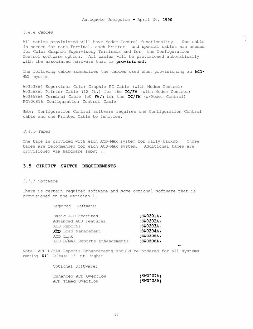
Autoquote Userguide - April 20, 1580
3.4.4 Cables
All cables provisioned will have Modem Control functionality. One cableis needed for each Terminal, each Printer, and special cables are neededfor Color Graphic Supervisory Terminals and for the ConfigurationControl software option. All cables will be provisioned automaticallywith the associated hardware that is provisioned.-
The following cable summarizes the cables used when provisioning an ACD-MAX system:
A0353364 Supervisor Color Graphic PC Cable (with Modem Control)A0356365 Printer Cable (12 ft.) for the TC/FM (with Modem Control)A0365366 Terminal Cable (50 ft:) for the TC/FM (w/Modem Control)PO700816 Configuration Control Cable
Note: Configuration Control software requires one Configuration Controlcable and one Printer Cable to function.
3.4.5 Tapes
One tape is provided with each ACD-MAX system for daily backup. Threetapes are recommended for each ACD-MAX system. Additional tapes areprovisioned via Hardware Input 7.
3.5 CIRCUIT SWITCH REQUIREMENTS
3.5.1 Software
There is certain required software and some optional software that isprovisioned on the Meridian 1.
Required Software:
Basic ACD Features (SW0201A)Advanced ACD Features (SW0202A)ACD Reports (SW0203A)Z&D Load Management (SW0204A)ACD Link (SW0205A)ACD-D/MAX Reports Enhancements (SW0206A)
_-Note: ACD-D/MAX Reports Enhancements should be ordered for-all systemsrunning X11 Release 13 or higher.
Optional Software:
Enhanced ACD OverflowACD Timed Overflow
(SW0207A)(SW0208A)
10

Autoquote Userguide - April 20, 1990
3.5,.2 Serial Data Interface (SDI)
The ACD-MAX is connected to the Meridian 1 via an SD1 port and a HighSpeed Link cable. The High Speed Link cable is provided in the ACD-MAXsystem package, and the SD1 port will be provisioned on the Meridianwhen ACD Load Management Software iS provisioned.
11

AutoquOte Userguide - April 20, 1990
,;
.. . .
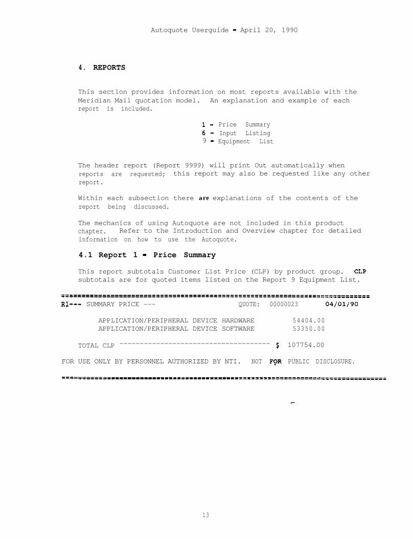
Autoquote Userguide - April 20, 1990
4. REPORTS
This section provides information on most reports available with theMeridian Mail quotation model. An explanation and example of eachreport is included.
l- Price Summary6- Input Listing9 - Equipment List
The header report (Report 9999) will print Out automatically whenreports are requested; this report may also be requested like any otherreport.
Within each subsection there are explanations of the contents of thereport being discussed.
The mechanics of using Autoquote are not included in this productchapter. Refer to the Introduction and Overview chapter for detailedinformation on how to use the Autoquote.
4.1 Report 1 - Price Summary
This report subtotals Customer List Price (CLP) by product group. CLPsubtotals are for quoted items listed on the Report 9 Equipment List.
=====================‘pD=p’======================================================
Rl--- SUMMARY PRICE --- QUOTE: 00000023 04/01/90
APPLICATION/PERIPHERAL DEVICE HARDWARE 54404.00APPLICATION/PERIPHERAL DEVICE SOFTWARE 53350.00
TOTAL CLP ------------------------------------- $ 107754.00
FOR USE ONLY BY PERSONNEL AUTHORIZED BY NTI. NOT FCR PUBLIC DISCLOSURE.
--
13
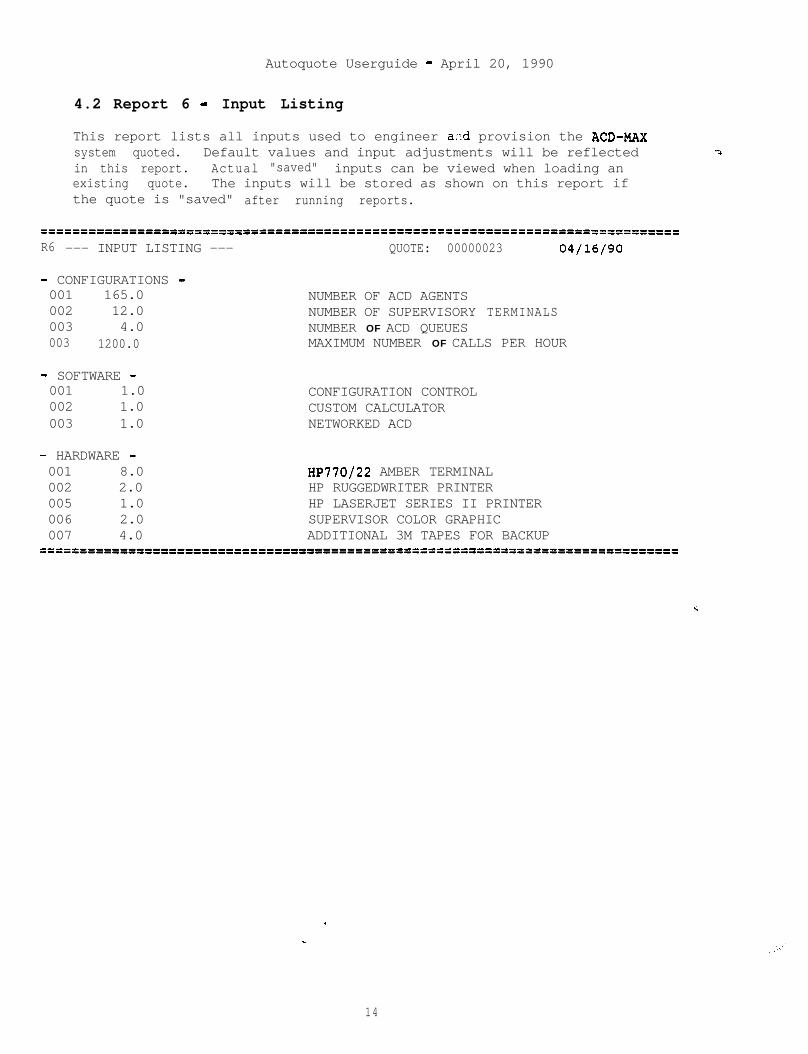
Autoquote Userguide - April 20, 1990
4.2 Report 6 - Input Listing
This report lists all inputs used to engineer azd provision the ACD-MAXsystem quoted. Default values and input adjustments will be reflectedin this report. Actual "saved" inputs can be viewed when loading anexisting quote. The inputs will be stored as shown on this report ifthe quote is "saved" after running reports.
===========-------=============================================================R6 --- INPUT LISTING --- QUOTE: 00000023 04/16/90
- CONFIGURATIONS -001 165.0 NUMBER OF ACD AGENTS002 12.0 NUMBER OF SUPERVISORY TERMINALS003 4.0 NUMBER OF ACD QUEUES003 1200.0 MAXIMUM NUMBER OF CALLS PER HOUR
- SOFTWARE -001 1.0 CONFIGURATION CONTROL002 1.0 CUSTOM CALCULATOR003 1.0 NETWORKED ACD
- HARDWARE -001 8.0 HP770/22 AMBER TERMINAL002 2.0 HP RUGGEDWRITER PRINTER005 1.0 HP LASERJET SERIES II PRINTER006 2.0 SUPERVISOR COLOR GRAPHIC007 4.0 ADDITIONAL 3M TAPES FOR BACKUP
===============================lfP================================================
14
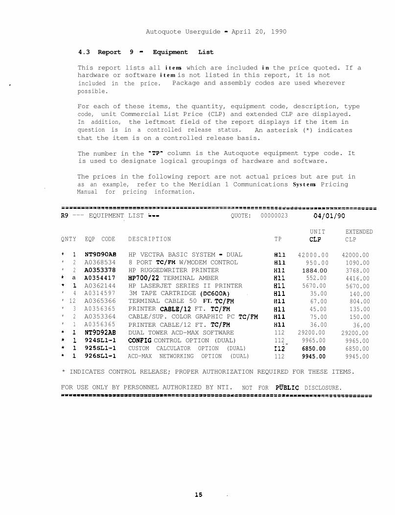
Autoquote Userguide - April 20, 1990
4.3 Report 9 - Equipment List
This report lists all items which are included in the price quoted. If ahardware or software item is not listed in this report, it is notincluded in the price. Package and assembly codes are used whereverpossible.
For each of these items, the quantity, equipment code, description, typecode, unit Commercial List Price (CLP) and extended CLP are displayed.In addition, the leftmost field of the report displays if the item inquestion is in a controlled release status. An asterisk (*) indicatesthat the item is on a controlled release basis.
The number in the "TP" column is the Autoquote equipment type code. Itis used to designate logical groupings of hardware and software.
The prices in the following report are not actual prices but are put in. as an example, refer to the Meridian 1 Communications Systems Pricing
Manual for pricing information.
=======o================xzp=========1==B========================================
R9 --- EQUIPMENT LIST :-- QUOTE: 00000023 04/01/90.
QNTY EQP CODE DESCRIPTION TP
* 1 NT9D90AB HP VECTRA BASIC SYSTEM - DUAL Hll 42000.00 42000.00* 2 A0368534 8 PORT TC/FM W/MODEM CONTROL Hll 950.00 1090.00* 2 A0353378 HP RUGGEDWRITER PRINTER Hll 1884.00 3768.00* a A0354417 HP700/22 TERMINAL AMBER Hll 552.00 4416.00*1 A0362144 HP LASERJET SERIES II PRINTER Hll 5670.00 5670.00* 4 A0314597 3M TAPE CARTRIDGE (DC600A) . Hll 35.00 140.00* 12 A0365366 TERMINAL CABLE 50 FT. TC/FM Hll 67.00 804.00* 3 A0356365 PRINTER CABLE/12 FT. TC/FM Hll 45.00 135.00* 2 A0353364 CABLE/SUP. COLOR GRAPHIC PC TC/FM Hll 75.00 150.00* 1 A0356365 PRINTER CABLE/12 FT. TC/FM Hll 36.00 36.00*1 NT9D92AB DUAL TOWER ACD-MAX SOFTWARE 112 29200.00 29200.00*1 924SLl-1 CONFIG CONTROL OPTION (DUAL) 112 9965.00 9965.00*1 925SLl-1 CUSTOM CALCULATOR OPTION (DUAL) 112- 6850.00 6850.00*1 926SLl-1 ACD-MAX NETWORKING OPTION (DUAL) 112 9945.00 9945.00
UNITCLP
EXTENDEDCLP
* INDICATES CONTROL RELEASE; PROPER AUTHORIZATION REQUIRED FOR THESE ITEMS.
FOR USE ONLY BY PERSONNEL AUTHORIZED BY NTI. NOT FOR .PUBLIC DISCLOSURE.311111P1300rlII'="=PftflPDPfft==IIDI=I========================================

Autoquote Ueerguide - April 20, 1990
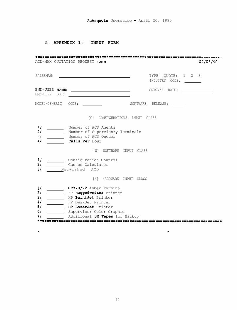
Autoguote Userguide - April 20, 1990
5. APPENDIX 1: INPUT FORM
===========i===================================================================
ACD-MAX QUOTATION REQUEST FORM 04/06/90
SALESMAN: TYPE QUOTE: 1 2 3INDUSTRY CODE:
END-USER NAME: CUTOVER DATE:END-USER LOC:
MODEL/GENERIC CODE: SOFTWARE RELEASE:
[C] CONFIGURATIONS INPUT CLASS
11 Number of ACD Agents21 Number of Supervisory Terminals31 Number of ACD Queues41 Calls Per Hour
[S] SOFTWARE INPUT CLASS
1/ Configuration Control21 Custom Calculator31 Networked ACD
[H] HARDWARE INPUT CLASS
1/ HP770/22 Amber Terminal21 HP RuggedWriter Printer31 HP PaintJet Printer41 HP DeskJet Printer51 HP LaserJet Printer61 Supervisor Color Graphic7/ Additional 3M Tapes for Backup==P===PPID========o====================P========----------------====----------
4 -
17

\:
;:’
_-
Meridian I
AUTOQUOTE USER GUIDE
MERIDIAN MS-1
nit northorntelecom

_-
Autoguote Userguide - April 20, 1990
MERIDIAN MS-1MEETING COMMUNICATION SYSTEMAUTOQUOTE USER GUIDE CHAPTER
1. INTRODUCTION .............. ..o- ........................... 1
1.1 PRODUCT DESCRIPTION ............................. ..l
1.2 VALID MODELS .................................... ..l
2 . INPUT ................................................... 3
2.1 INPUT CLASSE.................... . . . . . . . . . . . . . . . . . . 3
2.2 INPUT2.2.12 . 2 . 2
CODES, DESCRIPTIONS, AND DEFAULT VALUES.....3System Option.......,......... . . . . . . . . . . . . . . . . . . . . . . . 3Peripherals......... . . . . . . . . . . . . . . . . . . . . . . . . . . . . . . . . . 4
3. ENGINEERING/PROVISIONING . . . . . . . . . . . . . . . . . . . . . . . . . . . . . . . . 5
3.1 SOFTWARE PROVISIONING ............................. 53.1.1 MS-1 Software ........................................ 53.1.2 Reservations Software .............................. ..S
3.2 HARDWARE PROVISIONING .......................... ...53.2.1 Conference Bridge Assembly ......................... ..S3.2.2 Application Processor ................................ 53.2.3 Trunking ............................................ 6
3.2.3.2 Ground Start Bundle ......................... 63.2.3.3 I-Wire E&M Bundle ........................... 6
3.2.4 Power Equipment ...................................... 63.2.4.1 1lOV AC Power Supply ........................ 63.2.4.2 (-) 48V DC Power Converter .................. 63.2.4.3 (-) 48V DC Wiring Harness ................... 7
3.2.5 Miscellaneous Equipment .............................. 73.2.5.1 Digital Trunk Cable (SO') ................... 73.2.5.2 Connector Kit ............................... 73.2.5.3 MS-l Cabinet ................................ 73.2.5.4 Cabinet Door Latch .......................... 73.2.5.5 Input Jumper ................................ 73.2.5.6 Vertical Jumper ............................. 7-3.2.5.7 Horizontal Jumper ........................... 7
3.2.6 Terminal Device ...................................... 73.2.6.1 M4020 Terminal .............................. 83.2.6.2 LAN Interface Unit (LIU) .................... 83.2.6.3 System Matrix Printer ....................... 83.2.6.4 Parallel Printer Cable (10') ................ 83.2.6.5 Serial Printer Cable (10') .................. 8

Autoquote Ueerguide - April 20, 1990
4. REPORTS ................................................. 9
4.1 Price Summary - Report ........................... .
4.2 Equipment List - Report ....................... ..lO
4.3 Input Listing - Report 6...........'..............11
5. APPENDIX 1: INPUT FORM . . . . . . . . . . . . . . . . . . . . . . . . . . . . . . . . 1 3
:
i i
Autoguote Userguide - April 20, 1990
1. INTRODUCTION
This chapter of the Meridian Business Systems Autoguote User Guideprovides information on quoting the Meridian MS-1,Meeting CommunicationSystem. The mechanics of using Autoquote are not included in thisproduct chapter.- Refer to the Introduction and Overview chapter fordetailed information on how to use the Autoquote System.
1.1 PRODUCT DESCRIPTION
The Meridian MS-1 Meeting Communication System is a digital, audio tele-conferencing system providing superior audio quality for up to forty-eight simultaneous users.
1.2 VALID MODELS
There are two Meridian MS-1 Autoquote models.
Model Generic Release
Meridian MS-1On-line Input Form
MS1MSlF
<cr>ccr>
Since neither model has an associated release, simply enter a carriagereturn at the release prompt.
.
1

Autoquote Userguide - April 20, 1990
.
Autoquote Userguide - April 20, 1990
2 . INPUTS
This section covers all inputs associated with the Meridian MS-lgeneric.
As with all Autoquote models, data input consists of responses toprompted entries and manual inputs associated with specific input codes.A blank input form is included in the back of this chapter. It isrecommended that copies be used for preparing quotations. An on-lineinput form is also available on the Autoquote system (Model/Generic"MSlF"). .
2.1 INPUT CLASSES
Meridian MS-1 inputs are organized into two input classes:
.
System Options [SlPeripherals [PI
When creating a new quote, Autoquote will prompt for each input class inthe order listed above. The letter designation is used to makeselections from the Input Menu.
2.2 INPUT CODES, DESCRIPTIONS, AND DEFAULT VALUES
The following pages contain information on each Meridian MS-1 input:codes, descriptions, and default values where appropriate.
2.2.1 System Options
All System Options inputs accept one entry.
1 Number of Ports
Enter the number of ports desired for the system. Thisvalue determines the maximum number of participants (in oneor more conference) supported at one time. The appropriatesystem package, 18, 24, or 48 port, will be provisioned.
2 Trunk Type (l=Tl, ?=Ground Start, 3=4-Wire E&M)
This input indicates the type of trunking to be utilized.Enter one (1) for Digital Tl, two (2) for Analog GroundStart, or three (3) for 4-Wire E&M trunks.
3 Power Indicator (l=AC, 2=DC)
Enter one (1) to provision 1lOV AC power equipment or two(2) to provision -48V DC equipment.
3
Autoquote Userguide - April 20, 1990
50 Reservations Software
Enter one (1) if Reservations functionality is desired.
2.2.2 Peripherals
All Peripherals inputs accept one entry.
1 M4020 Terminals
Enter the number desired. The MS-1 supports a maximum offive terminals.
20 Additional LA?4 Interface Unit (LIU)
Enter one (1) for an additional LIU.
30 System Matrix Printer to M4020
.
Enter one (1) if a System Printer is to be connected to aM4020 terminal. Only one System Printer may be requestedper system.
32 System Matrix Printer to LIU
Enter one (1) if a System Printer is to be connected to anLIU. Only one System Printer may be requested be persystem.
Autoguote Userguide - April 20, 1990
3. ENGINEERING/PROVISIONING
This section contains the engineering/provisioning rules used togenerate Meridian MS-1 configurations.
3.1 SOFTWARE PROVISIONING
The current Meridian MS-1 release offers base software features and oneoptional feature.
3.1.1 MS-1 Software
Base software features are included in each Conference Bridge Assembly.The assembly provisioned is determined by the number of ports requested(System Options input 1).
Ports Assembly1-18 NT4G81SB 18 Port MS-1 Software
19-24 NT4G81TB 24 Port M S - l Software25-48 NT4G81UB 48 Port MS-1 Software
3.1.2 Reservations Software
NT4GSlYE Reservations Software allows attendants to make reservations upto 12 months in advance. This is quoted by entering a one for SystemOptions input 50.
3.2 HARDWARE PROVISIONING
The following subsections summarize the hardware provisioned fordifferent input parameters.
3.2.1 Conference Bridge Assembly
One assembly is provisioned for each quote. The actual assembly isdetermined by the number of ports requested (System Options input 1).
Ports1-18
19-2425-48
AssemblyNTMS1800 18 Port Conference Bridge AssemblyNTMS2400 24 Port Conference Bridge AssemblyNTMS4800 48 Port Conference Bridge Assembly
3.2.2 Application Processor
One 3 MB Applications Processor NT4G25CA is required to supportReservations Software. It is quoted if a one is entered for SystemOptions input 50.
5
Autoquote Userguide - April 20, 1990
3.2.3 Trunk'ing
An MS-1 system may be configured to support Tl, Ground Start, or 4-WireE&M trunking. The appropriate hardware is provisioned as follows.
3.2.3.1 Digital Trunk Link SRU
The NT4G23BA Digital Trunk Link SRU is provisioned if a one is enteredfor System Options input 2, indicating Tl trunking. Two are quoted if a48 Port Conference Bridge Assembly is provisioned, otherwise only one isquoted. One NT4G23AD cable is required for each Digital Trunk Link.
3.2.3.2 Ground Start Bundle
Ground Start trunking is quoted if a two is entered for input number 2,indicating Ground Start trunking. The assembly provisioned isdetermined by the number of ports requested (System Options input 1).
Ports Assemblyl-18 NTlGS18 18 Port Ground Start Bundle
19-24 NTlGS24 24 Port Ground Start Bundle25-48 NTlGS48 48 Port Ground Start Bundle
3.2.3.3 4-Wire E&M Bundle
4-Wire E&M trunking is quoted if a three is entered for input number 2,indicating 4-Wire E&M trunking. The assembly provisioned is determinedby the number of ports requested, (System Options input 1).
Portsl - 1 8
1 9 - 2 425-48
AssemblvNTlEM18 18 Port E&M BundleNTlEM24 24. Port E&M BundleNTlEM48 48 Port E&M Bundle
3.2.4 Power Equipment
An MS-l system may be provisioned with either 1lOV AC or -48V DC power.The appropriate equipment is provisioned as follows.
3.2.4.1 1lOV AC Power Supply
Each cabinet requires one 1lOV AC Power Supply if AC power is requestedby entering a 1 for System Option input 3.
3.2.4.2 (-) 48V DC Power Converter
Each cabinet requires one -48V DC Power Converter if DC power isrequested by entering a 2 for System Option input 3.
6
AutoquOte Userguide - April 20, 1990
3.2.4.3 (-) 48V DC Wiring Harness
One is provisioned for each -48V DC Power Converter quoted.
3.2.5 Miscellaneous Equipment
Additional equipment is provisioned according to the following rules.
3.2.5.1 Digital Trunk Cable (50')
One is provisioned for each Digital Trunk Link quoted.
3.2.5.2 Connector Kit
Two are quoted if a 48 Port Conference Bridge Assembly is provisioned,otherwise only one is quoted.
3.2.5.3 MS-l Cabinet
The number quoted depends solely on card slot requirements for theequipment provisioned. There are no power or thermal restrictions forthe MS-l Cabinets.
The following guidelines specify the number quoted:
- All 18 port systems require two cabinets.
- Three cabinets are necessary for 24 port systems utilizing 4-Wire E&M trunking. All other 24 port systems require twocabinets.
- Two cabinets are needed for 48 port systems with Tl trunking, ACpower, and no Reservations software. All other 48 port systemsrequire three cabinets.
3.2.5.4 Cabinet Door Latch
Each cabinet requires a Cabinet Door Latch.
3.2.5.5 Input Jumper
One is provisioned for each quote.
3.2.5.6 Vertical Jumper
One is provisioned for each quote.
3.2.5.7 Horizontal Jumper
The number provisioned equals the number of cabinets quoted minus one.
3.2.6 Terminal Devices
The following terminal devices are provisioned as follows.
7
Autoguote Userguide - April 20, 1990
3.2.6.1 M4020 Terminal
The number quoted equals the number requested (Peripherals input 10).A maximum of five terminals may be supported by an MS-1 system.
3.2.6.2 LAN Interface Unit (LIU)
One is quoted if either a LAN Interface Unit ,(Peripherals input 20) or aSystem Matrix Printer (Peripherals input 32) to LIU is requested. Amaximum of one LIU may be included in a quote.
3.2.6.3 System Matrix Printer
Onesis quoted if either a System Matrix Printer to M4020 (System Optionsinput 30) or System Matrix Printer to LIU (System Options input 32) isrequested. A maximum of one may be supported by an MS-1 system.
3.2.6.4 Parallel Printer Cable (10')
One is provisioned for each System Matrix Printer to LIU requested(System Options input 32).
3.2.6.5 Serial Printer Cable (10')
One is provisioned for each System Matrix Printer connected to a M4020terminal.
8
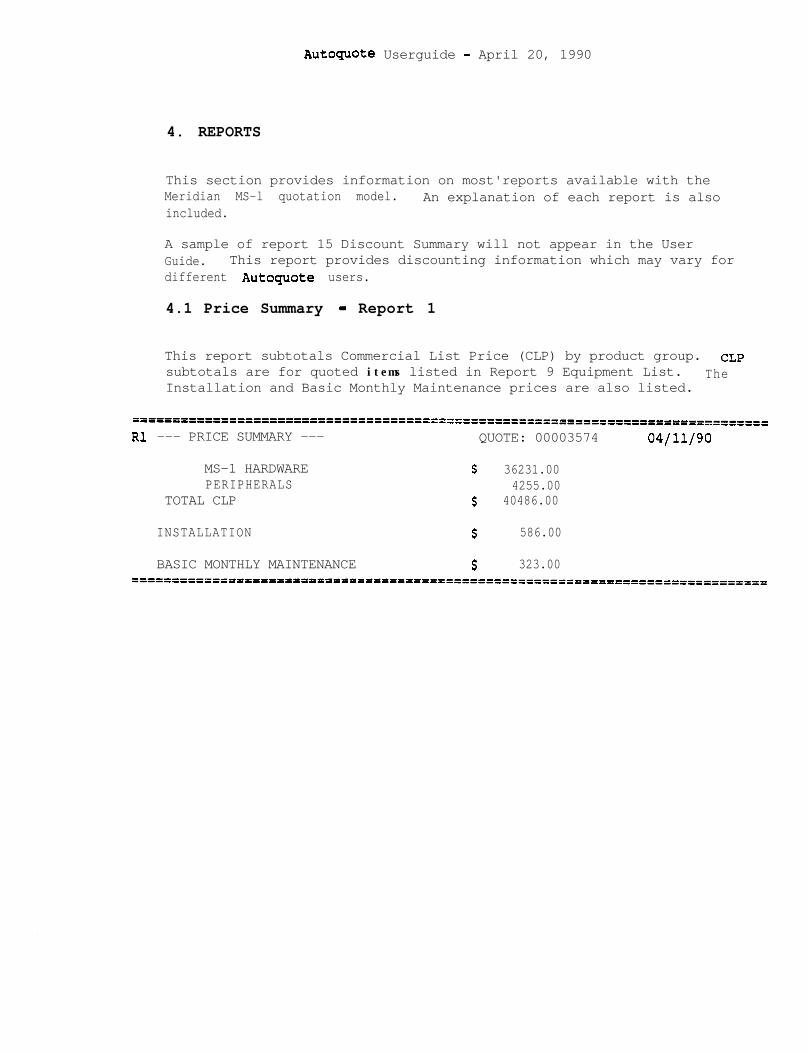
Autoquote Userguide - April 20, 1990
4. REPORTS
This section provides information on most'reports available with theMeridian MS-l quotation model. An explanation of each report is alsoincluded.
A sample of report 15 Discount Summary will not appear in the UserGuide. This report provides discounting information which may vary fordifferent AutOquOte users.
4.1 Price Summary - Report 1
This report subtotals Commercial List Price (CLP) by product group. CLPsubtotals are for quoted items listed in Report 9 Equipment List. TheInstallation and Basic Monthly Maintenance prices are also listed.
======================DP==========IP========================================
Rl --- PRICE SUMMARY --- QUOTE: 00003574 04/11/90
MS-1 HARDWARE $ 36231.00PERIPHERALS 4255.00
TOTAL CLP $ 40486.00
INSTALLATION $ 586.00
BASIC MONTHLY MAINTENANCE $ 323.00=====t=============='=============================================================
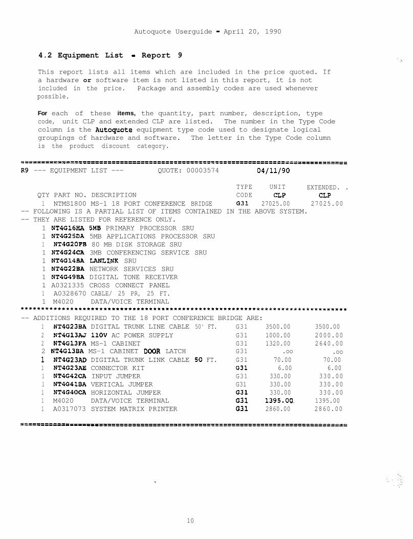
Autoquote Userguide - April 20, 1990
4.2 Equipment List - Report 9
This report lists all items which are included in the price quoted. Ifa hardware or software item is not listed in this report, it is notincluded in the price. Package and assembly codes are used wheneverpossible.
For each of these items, the quantity, part number, description, typecode, unit CLP and extended CLP are listed. The number in the Type Codecolumn is the Autoguote equipment type code used to designate logicalgroupings of hardware and software. The letter in the Type Code columnis the product discount category.
------------__----------------------------------------===p=’=================================================
R9 --- EQUIPMENT LIST --- QUOTE: 00003574 04/11/90
TYPE UNIT EXTENDED. .QTY PART NO. DESCRIPTION CODE CLP CLP1 NTMS1800 MS-1 18 PORT CONFERENCE BRIDGE G31 27025.00 27025.00
-- FOLLOWING IS A PARTIAL LIST OF ITEMS CONTAINED IN THE ABOVE SYSTEM.-- THEY ARE LISTED FOR REFERENCE ONLY.
1 NT4G16HA SMB PRIMARY PROCESSOR SRU1 NT4G25DA 5MB APPLICATIONS PROCESSOR SRU1 NT4G20FB 80 MB DISK STORAGE SRU1 NT4G24CA 3MB CONFERENCING SERVICE SRU1 NT4G14BA LANLINK SRU1 NT4G22BA NETWORK SERVICES SRU1 NT4G49BA DIGITAL TONE RECEIVER1 A0321335 CROSS CONNECT PANEL1 A0328670 CABLE/ 25 PR, 25 FT.1 M4020 DATA/VOICE TERMINAL
*******************************************************************************-- ADDITIONS REQUIRED TO THE 18 PORT CONFERENCE BRIDGE ARE:
1 NT4G23BA DIGITAL TRUNK LINE CABLE 50' FT. G31 3500.00 3500.002 NT4G13AJ 1lOV AC POWER SUPPLY G31 1000.00 2000.002 NT4G13FA MS-1 CABINET G31 1320.00 2640.002 NT4G13BA MS-1 CABINET DOOR LATCH G31 .oo .oo1 NT4G23AD DIGITAL TRUNK LINK CABLE 50 FT. G31 70.00 70.001 NT4G23AE CONNECTOR KIT G31 6.00 6.001 NT4G42CA INPUT JUMPER G31 330.00 330.001 NT4G41BA VERTICAL JUMPER G31 330.00 330.001 NT4G40CA HORIZONTAL JUMPER G31 330.00 330.001 M4020 DATA/VOICE TERMINAL G31 1395.OQ 1395.001 A0317073 SYSTEM MATRIX PRINTER G31 2860.00 2860.00
w .
10
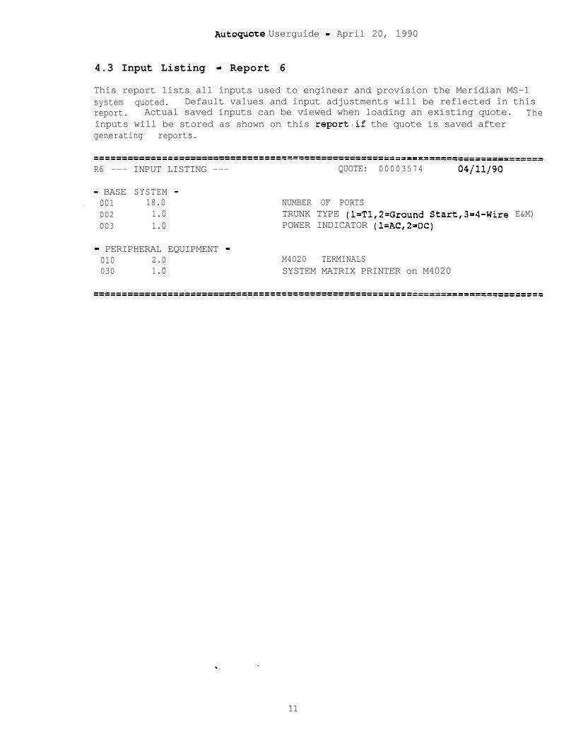
AutOcpOte Userguide - April 20, 1990
4.3 Input Listing - Report 6
This report lists all inputs used to engineer and provision the Meridian MS-1system quoted. Default values and input adjustments will be reflected in thisreport. Actual saved inputs can be viewed when loading an existing quote. Theinputs will be stored as shown on this report.if the quote is saved aftergenerating reports.
======================f====================================================------R6 --- INPUT LISTING --- QUOTE: 00003574 04/11/90
- BASE SYSTEM -. 001 18.0 NUMBER OF PORTS
002 1.0 TRUNK TYPE (l=T1,2=Ground Start,3=4-Wire E&M)003 1.0 POWER INDICATOR (l=AC,2=DC)
- PERIPHERAL EQUIPMENT -010 2.0 M4020 TERMINALS030 1.0 SYSTEM MATRIX PRINTER on M4020
11

AutOquOte Userguide - April 20, 1990
--
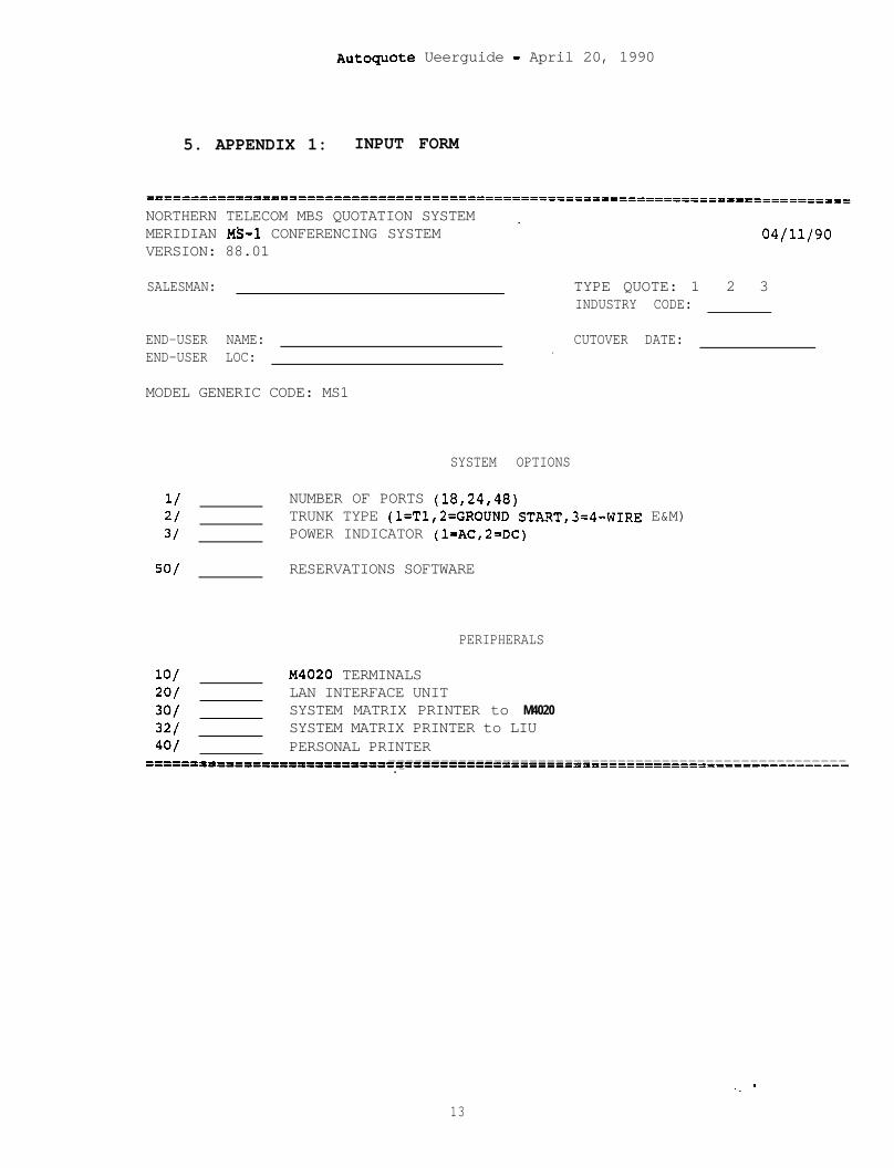
Autoguote Ueerguide - April 20, 1990
5. APPENDIX 1: INPUT FORM
NORTHERN TELECOM MBS QUOTATION SYSTEM _MERIDIAN MS-1 CONFERENCING SYSTEMVERSION: 88.01
SALESMAN: TYPE QUOTE: 1INDUSTRY CODE:
04/11/90
2 3
END-USER NAME: CUTOVER DATE:END-USER LOC: .
MODEL GENERIC CODE: MS1
1/2/31
5O/
SYSTEM OPTIONS
NUMBER OF PORTS (18,24,48)TRUNK TYPE (l=T1,2=GROUND START,3=4-WIRE E&M)POWER INDICATOR (l=AC,2=DC)
RESERVATIONS SOFTWARE
PERIPHERALS
lo/ X4020 TERMINALSso/ LAN INTERFACE UNIT3C/ SYSTEM MATRIX PRINTER to M4020
321 SYSTEM MATRIX PRINTER to LIU401 PERSONAL PRINTER
=P==ilft=I=PIPllfPP1=======--------------------------------------------------------------------------------------------------------.-
13

Autoquote Ueerguide - April 20, 1990
._.\
,-
.-
Meridian I
AUTOQUOTE USER GUIDE
I MERIDIAN MESSAGEaCENTER
I

‘.._
Autoguote Userguide - April 20, 1990
MERIDIAN MESSAGE CENTERAUTOQUOTE USER GUIDE CHAPTER'
1. INTRODUCTION . . . . . . . . . . . . . . . . . . . . . . . . . . . . . . . . . . . . . . . . . . . . 1
1.1 PRODUCT DESCRIPTION............;...................1
1.2 VALID MODELS......................................1
2. INPUT . . . . . . . . . . . . . . . . . . . . . . . . . . . . . . . . . . . . . . . . ..~........3
2.1 INPUT CLASSE......................................3
2.2 INPUT CODES, DESCRIPTIONS, AND DEFAULT VALUES.....32.2.1 System Option............... . . . . . . . . . . . . . . . . . . . . . . . . . 32.2.2 Peripherals........................... . . . . . :. . . . . . . . . 4
3. ENGINEERING/PROVISIONING ................................ 73.1.1 DTMF-ASCII Converter Box ............................. 73.1.2 DTMF-ASCII Converter Box Cable .................... ...73.1.3 SL-1 RS232 Connection Cable .......................... 73.1.4 M4010 Terminal ....................................... 73.1.5 NT220 Registry Terminal .............................. 73.1.6 Registry Terminal Cable ........................... ...73.1.7 Registry Terminal Enclosure ....................... ...73.1.8 1200 Baud Modem ...................................... 73.1.9 224 AT/D Modem ....................................... 83.1.10 202 T Modem ......................................... 83.1.11 Modem Cable ......................................... 83.1.12 Printer Cable ....................................... 83.1.13 Serial Ports...; .................................... 83.1.14‘Parallel Ports ...................................... 83.1.15 a-Port MUX Option ................................. ..a3.1.16 g-Pin Conversion Cable .............................. 83.1.17 LAN Interface Unit .................................. 83.1.18 Lanlink SRU ......................................... 9
4. REPORTS . . . . . . . . . . . . . . . . . . . . . . . . . . . . . . . . . . . . . . . . . . . . . . . . 11
4.1 Price Summary - Report ........................ ..ll
4.2 Equipment List - R&port ....... .,..;. .............. 12
. 4.3 Input Listing - Report 6.........................13
5: APPENDIX 1: INPUT FORM . . . . . . . . . . . . . . . . . . . . . . . . . . . . . . . . 15
i

Autoquote Userguide - April 20, 1990
Autoquote Userguide - April 20, 1990
1 . INTRODUCTION
This chapter of the Meridian Business Systems Autoguote User Guideprovides information on quoting the Meridian Message Center. Themechanics of using Autoquote are not included in this product chapter.Refer to the Introduction and Overview chapter for detailed informationon how to use the Autoguote System.
1.1 PRODUCT DESCRIPTION
The Meridian Message Center provides text messaging capabilities tobusiness and medical applications.
1.2 VALID MODELS
There are two Meridian Message Center hutoguote models.
Model Generic Release
Meridian Message Center MSG
On-line Input Form MSGF<co<co
Since,neither model has an associated release, simply enter a carriagereturn at the release prompt.

AutOquOte Ueerguide - April 20, 1990
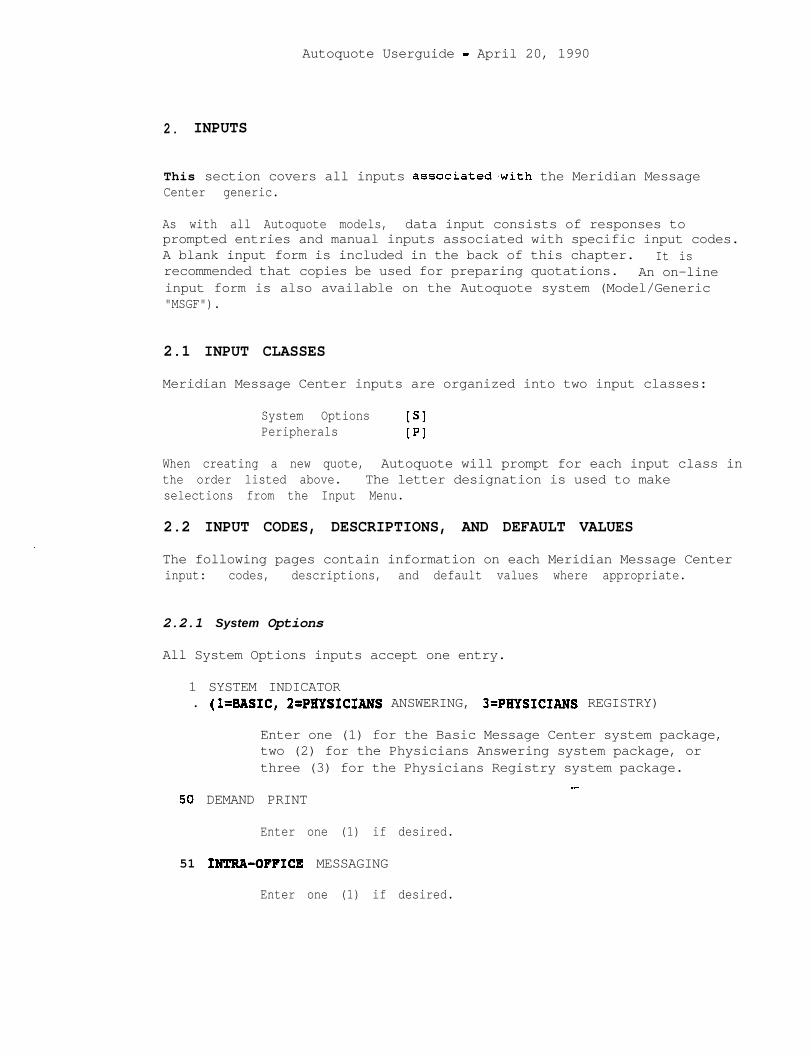
Autoquote Userguide - April 20, 1990
2. INPUTS
This section covers all inputs associated.with the Meridian MessageCenter generic.
As with all Autoquote models, data input consists of responses toprompted entries and manual inputs associated with specific input codes.A blank input form is included in the back of this chapter. It isrecommended that copies be used for preparing quotations. An on-lineinput form is also available on the Autoquote system (Model/Generic"MSGF").
2.1 INPUT CLASSES
Meridian Message Center inputs are organized into two input classes:
System Options PIPeripherals [PI
When creating a new quote, Autoquote will prompt for each input class inthe order listed above. The letter designation is used to makeselections from the Input Menu.
2.2 INPUT CODES, DESCRIPTIONS, AND DEFAULT VALUES
The following pages contain information on each Meridian Message Centerinput: codes, descriptions, and default values where appropriate.
2.2.1 System Options
All System Options inputs accept one entry.
1 SYSTEM INDICATOR. (l=BASIC, 2=PRYSICIANS ANSWERING, 3=PRYSICIANS REGISTRY)
Enter one (1) for the Basic Message Center system package,two (2) for the Physicians Answering system package, orthree (3) for the Physicians Registry system package.
50 DEMAND PRINT_-
Enter one (1) if desired.
51 IN!CRA-OFFICE MESSAGING
Enter one (1) if desired.

Autoquote Userguide - April 20, 1990
52 PAGER INTERFACE
Enter one (1) if desired.
53 PHYSICIANS REFERRAL
Enter one (1) if desired.
54 PRE-PROGRAMMED MESSAGES
55 REMOTE DEMAND PRINT
Enter one (1) if desired.
56 USER CHANGE OF STATUS
Enter one (1) if desired.
57 SL-1 AUTO SCREEN ACTIVATION
Enter one (1) if desired.
60 SMDI AUTO SCREEN ACTIVATION (<=1000 LINES)
Enter one (1) if required to support less than 1000 lines.
61 SMDI AUTO SCREEN ACTIVATION ( >1000 LINES)
Enter one (1) if required to support over 1000 lines.
2.2.2 Peripherals
All Peripherals inputs accept one entry.
1 M4010 TERMINALS
Enter the quantity desired.
'2 REGISTRY TERMINALS (NT220)
Enter the quantity desired.
3 REGISTRY TERMINAL ENCLOSURES
Enter the quantity desired.
10 ADDITIONAL LAN INTERFACE UNITS
Znter the quantity desired.
11 ADDITIONAL LANLINK UNITS
Enter the quantigy desired.
4
Autoquote Userguide - April 20, 1990
12 8-PORT MUX OPTIONS
Enter the quantity desired.
13 PAGING INDICATOR (l=Tone/Digital, 2=Alphanumeric, 3=Both)
If paging functionality is desired, the type(s) of paging tobe supported must be specified. Enter one (1) for Tone orDigital paging Only, two (2) for Alphanumeric paging only,or three (3) for both Tone/Digital and Alphanumeric paging.
30 SYSTEM PRINTERS to LIU
Enter the number of system printers that are to be connectedto a LAN interface unit.
31 SYSTEM PRINTERS to M4010
Enter the number of system printers that are to be connectedto a M4010.
. .
5

Autoquote Userguide - April 20, 1990
.
Autoquote Userguide - April 20, 1990
3. ENGINEERING/PROVISIONING
This section contains the engineering/provisioning rules used togenerate Meridian Message Center configurations.
3.1.1 DTMF-ASCII Converter Box
One is required for each of the following software options: DemandPrint, Pre-Programmed Messages, and User Change of Status. Note thatone is included in the Demand Print assembly.
3.1.2 DTMF-ASCII Converter Box Cable
One is required for each DTMF-ASCII Converter Box
3.1.3 SL-1 RS232 Connection Cable
One is required for Auto-Screen Activation. Note that one is includedin the Basic Message Center base package.
3.1.4 M4010 Terminal
The number provisioned is equal to the number requested at Peripheralsinput 1. Two are included in all base system packages.
3.1.5 NT220 Registry Terminal
. The number provisioned is equal to the number requested at Peripheralsinput 2. One is included in the Physicians Registry base systempackage.
3.1.6 Registry Terminal Cable
The number provisioned is equal to the number of NT220 RegistryTerminals provisioned. One is included in the Physicians Registry basesystem package.
3.1.7 Registry Terminal Enclosure
The number provisioned is equal to the number requested at Peripheralsinput 3.
3.1.8 1200 Baud Modem
One is included in every system package. An additional 1200 Baud Modemis required for Alphanumeric paging.
Autoquote Userguide - April 20, 1990
3.1.9 224 AT/D Modem
One is required for Remote Demand Print.
3.1.10 202 T Modem
One is required for SMDI Auto-Screen Activation. -
3.1.11 Modem Cable
One is required for each of the following modems: 1200 Baud Modem, 224AT/D Modem, and 202 T Modem. One is included in every base systempackage.
3.1.12 Printer Cable
One is provisioned for each system printer to be connected to an LIU(Peripherals input 30).
3.1.13 Serial Ports
One serial port is required for each of the following: NT220 RegistryTerminal, SL-1 RS232 Connection Cable, 1200 Baud Modem, 224 AutodialModem, 202 T Modem, and DTMF-ASCII Converter Box. Serial ports arefound on both the LAN Interface Unit and 8-Port MUX Option.
3.1.14 Parallel Ports
One parallel port is required for each system printer to be connected toan LIU, indicated with Peripheral input 20. Parallel ports are found onboth the LAN Interface Unit and 8-Port MUX Option.
3.1.15 a-Port MUX Option
Each 8-Port MUX Option supports eight serial ports and one parallelport. The number provisioned is the number requested at Peripheralsinput 12.
3.1.16 g-Pin Conversion Cable
One is provisioned for each 8-Port MUX Option.
3.1.17 LAN Interface Unit -
Each LAN Interface Unit (LIU) supports two serial ports and one parallelport. The number of LIU*s required to support serial and parallel portsis calculated independently.
s= (SR- (8 * Ml) / 2
where S = LIU's to support serial ports.SR = Serial ports required.M = Number of 8yPort MUX Options.
8
Autoquote Userguide - April 20, 1990
P = (PR - (8 * M))
where P = LIU's to support parallel ports.PR = Parallel ports required.M = Number of a-Port MUX Options.
The maximum number of LIU's required to meet serial and parallel portrequirements plus any additional requested at Peripherals input 10determine the total number of LIU's provisioned.
L = maxi.mum(S,P) + A
where L = Number of LIU's provisioned.S = LIU's to support serial ports.P = LIjJ's to support parallel ports.A = Additional LIU's desired (Peripherals input 10).
Note that one LIU is contained in each base system package.
3.1.18 La&ink SRV
Each Lanlink SRU has eight ports to support the following: LAN InterfaceUnit, M4010 Terminal, and a-Port MUX Option. The number provisioned isdetermined as follows.
S =(L+T+M)/8+A
where S = Number of Lanlink SRU's provisioned.L = Number of LIU's provisioned.T = Number of M4010 Terminals provisioned.M- Number of 8'Port MUX Options provisioned.A = Additional Lanlink SRU's desired (Peripherals input 11).
A maximum of four Lanlink SRU's may be configured on any one MessageCenter system. Note that one Lanlink SRU is contained in each basesystem package.
9

p
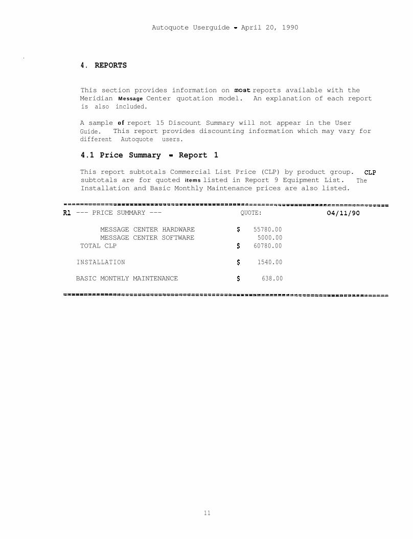
Autoquote Userguide - April 20, 1990
4. REPORTS
This section provides information on most reports available with theMeridian Message Center quotation model. An explanation of each reportis also included.
A sample of report 15 Discount Summary will not appear in the UserGuide. This report provides discounting information which may vary fordifferent Autoquote users.
4.1 Price Summary - Report 1
This report subtotals Commercial List Price (CLP) by product group. CLPsubtotals are for quoted items listed in Report 9 Equipment List. TheInstallation and Basic Monthly Maintenance prices are also listed.
------------=========================================================================Rl --- PRICE SUMMARY --- QUOTE: 04/11/90
MESSAGE CENTER HARDWARE S 55780.00MESSAGE CENTER SOFTWARE 5000.00
TOTAL CLP s 60780.00
INSTALLATION S 1540.00
BASIC MONTHLY MAINTENANCE S 638.00
11
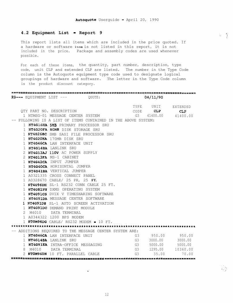
AutOquOte Userguide - April 20, 1990
4.2 Equipment List - Report 9
This report lists all items which are included in the price quoted. Ifa hardware or software item is not listed in this report, it is notincluded in the price. Package and assembly codes are used wheneverpossible.
For each of these items, the quantity, part number, description, typecode, unit CLP and extended CLP are listed. The number in the Type Codecolumn is the Autoquote equipment type code used to designate logicalgroupings of hardware and software. The letter in the Type Code columnis the product discount category.
==========================================================================-----R9--- EQUIPMENT LIST --- QUOTE: 04/11/90
TYPE UNIT EXTENDEDQTY PART NO. DESCRIPTION CODE CLP CLP1 NTMSG-01 MESSAGE CENTER SYSTEM G3 41400.00 41400.00
-- FOLLOWING IS A LIST OF ITEMS CONTAINED IN THE ABOVE SYSTEM:1 NT4G16HA 5MB PRIMARY PROCESSOR SRU1 NT4G2CFA 80MB DISK STORAGE SRU1 NT4G26BC SMB SASI FILE PROCESSOR SRU1 NT4G20HA 170MB DISK SRU1 NT4G46CA LAN INTERFACE UNIT1 NT4G14BA LANLINK SRU2 NT4G13AJ 1lOV AC POWER SUPPLY2 NT4G13FA MS-1 CABINET1 NT4G42CA INPUT JUMPER1 NT4G40CA HORIZONTAL JUMPER1 NT4G41BA VERTICAL JUMPER1 A0321335 CROSS CONNECT PANEL1 A0328670 CABLE/ 25 PR, 25 FT.1 NT4G96DH SL-1 RS232 CONN CABLE 25 FT.1 NT4G81PH DXMS OPERATING SYSTEM1 NT4G91CS DVIX V TIMESHARING SOFTWARE1 NTIGSlDA MESSAGE CENTER SOFTWARE1 NT4G91DB SL-1 AUTO SCREEN ACTIVATION1 NT4GSlDC DEMAND PRINT MODULE2 M4010 DATA TERMINAL1 A0344322 1200 BPS MODEM1 NTOM96DG CABLE/ RS232 MODEM - 10 FT.
*****************************************************************~~************-- ADDITIONS REQUIRED TO THE MESSAGE CENTER SYSTEM ARE:
1 NT4G46CA LAN INTERFACE UNIT G3 950.00 950.001 NT4G14BA LANLINK SRU G3 3000.00 3000.001 NTQGSlEA INTRA-OFFICE MESSAGING G3 5000.00 5000.008 M4010 DATA TERMINAL G3 1295.00 10360.002 NTOM96DN 10 FT. PARALLEL CABLE G3 35.00 70.00
====3f=I===PII--P100111POIIPflIPIPIPPOffl =='if=0=llfrl'l=fl=======IPPlt"=P==============
12
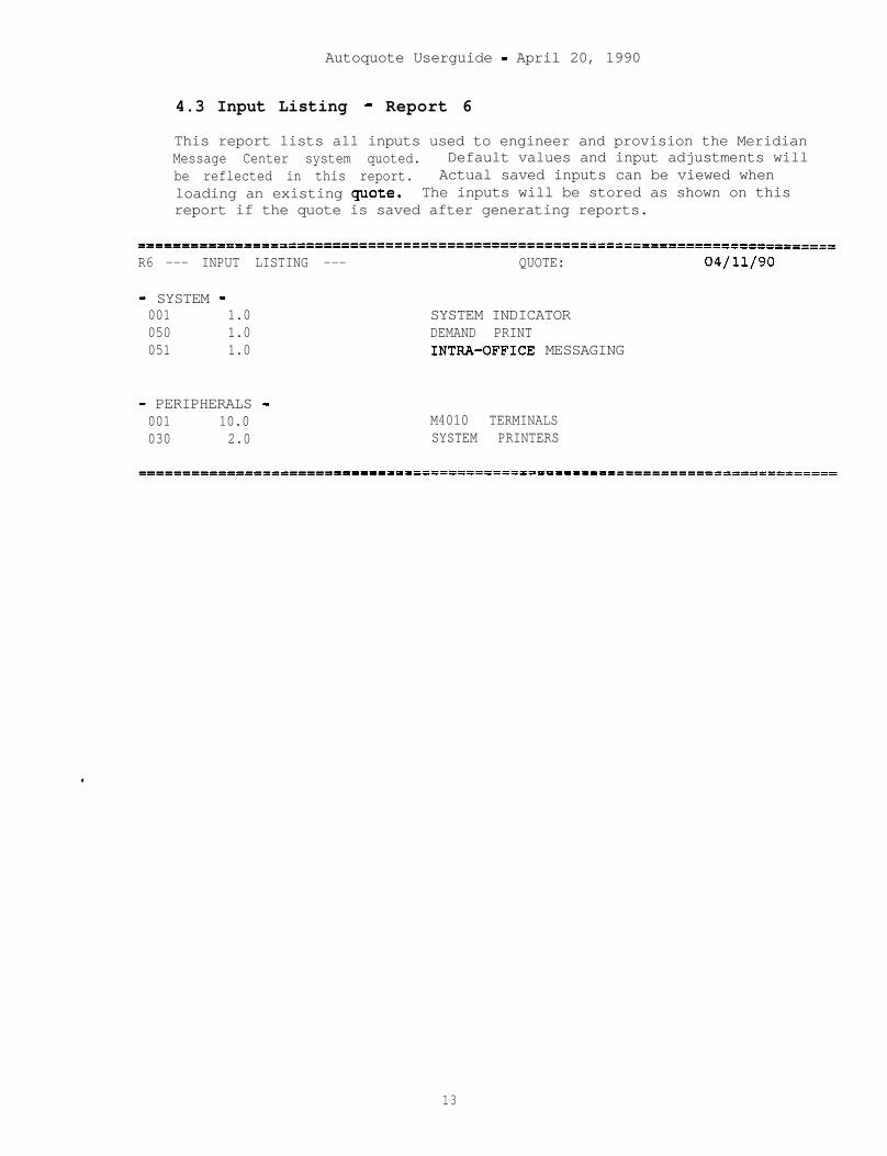
Autoquote Userguide - April 20, 1990
4.3 Input Listing - Report 6
This report lists all inputs used to engineer and provision the MeridianMessage Center system quoted. Default values and input adjustments willbe reflected in this report. Actual saved inputs can be viewed whenloading an existing quote. The inputs will be stored as shown on thisreport if the quote is saved after generating reports.
===--------------==================f===================================------R6 --- INPUT LISTING --- QUOTE: 04/11/90
- SYSTEM -001 1.0 SYSTEM INDICATOR050 1.0 DEMAND PRINT051 1.0 INTRA-OFFICE MESSAGING
- PERIPHERALS -001 10.0030 2.0
M4010 TERMINALSSYSTEM PRINTERS
13

Autoquote Userguide - April 20, 1990
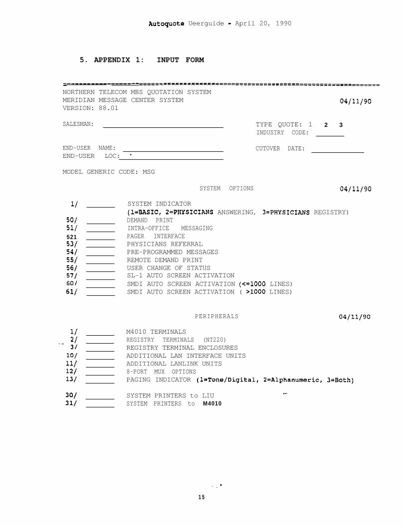
Autoguote Ueerguide - April 20, 1990
5. APPENDIX 1: INPUT FORM
--___________------------_ ------===============================================-------NORTHERN TELECOM MBS QUOTATION SYSTEMMERIDIAN MESSAGE CENTER SYSTEMVERSION: 88.01
SALESMAN: TYPE QUOTE: 1INDUSTRY CODE:
04/11/90
2 3
END-USER NAME: CUTOVER DATE:END-USER LOC: *
MODEL GENERIC CODE: MSG
11
50/51/52153/54155/56/57/60/61/
1/__ 2/
3/lo/11/12/13/
30131/
SYSTEM OPTIONS 04/11/90
SYSTEM INDICATOR(l=BASIC, 2=PHYSICIANS ANSWERING, 3=PHYSICIANS REGISTRY)DEMAND PRINTINTRA-OFFICE MESSAGINGPAGER INTERFACEPHYSICIANS REFERRALPRE-PROGRAMMED MESSAGESREMOTE DEMAND PRINTUSER CHANGE OF STATUSSL-1 AUTO SCREEN ACTIVATIONSMDI AUTO SCREEN ACTIVATION (<=lOOO LINES)SMDI AUTO SCREEN ACTIVATION ( >lOOO LINES)
04/11/90PERIPHERALS
M4010 TERMINALSREGISTRY TERMINALS (NT220)REGISTRY TERMINAL ENCLOSURESADDITIONAL LAN INTERFACE UNITSADDITIONAL LANLINK UNITS8-PORT MUX OPTIONSPAGING INDICATOR (l=Tone/Digital, 2=Alphanumeric, 3=Both)
SYSTEM PRINTERS to LIU _-
SYSTEM PRINTERS to M4010
. . -
15