Embed Size (px)
Citation preview

Number: 593
Originally Issued: 05/23/2019 Revised: 05/29/2020 Valid Through: 05/31/2021
The product described in this Uniform Evaluation Service (UES) Report has been evaluated as an alternative material, design or method of construction in order to satisfy and comply
with the intent of the provision of the code, as noted in this report, and for at least equivalence to that prescribed in the code in quality, strength, effectiveness, fire resistance, durability
and safely, as applicable, in accordance with IBC Section 104.11. This document shall only be reproduced in its entirety.
Copyright © 2020 by International Association of Plumbing and Mechanical Officials. All rights reserved. Printed in the United States. Ph: 1-877-4IESRPT • Fax: 909.472.4171
web: www.uniform-es.org • 4755 East Philadelphia Street, Ontario, California 91761-2816 – USA
Page 1 of 13
INNOVATIVE STRUCTURAL
SOLUTIONS
375 EAST 400 NORTH
MORGAN, UTAH 84050
(801) 510-7770
http://www.innstruct.com
INNSTRUCT SMART WALL/EVG-3D
PANELS
CSI Sections: 03 00 00 - CONCRETE
03 37 00 – Specialty Placed Concrete
1.0 EVALUATION SCOPE
The INNSTRUCT Smart Wall/EVG-3D panels
described in this report are used in the construction of
exterior and interior, load-bearing and non-load-
bearing, shear and non-shear walls, floors, and roofs in
fire-resistance-rated and non-fire-resistance-rated
construction. The structural and fire-resistance
properties of the INNSTRUCT Smart Wall/EVG-3D
panels were evaluated for compliance with the
following codes:
• 2018 and 2015 International Building Code®
(IBC)
• 2018 and 2015 International Residential
Code® (IRC)
• 2019 California Building Code (CBC) – See
attached Supplement
• 2019 California Residential Code (CRC) –
See attached Supplement
2.0 LIMITATIONS
Use of the INNSTRUCT Smart Wall/EVG-3D panels
described in this report are subject to the following
limitations:
The INNSTRUCT Smart Wall/EVG-3D panels shall
be installed in accordance with Section 3.2 of this
report, the manufacturer’s installation instructions,
and the IBC® or IRC®. Where conflicts occur, the
more restrictive shall govern.
2.1 Construction documents, statement of special
inspections, geotechnical report, and other data shall
be submitted to the building official for approval. The
applicable provisions in this report and the IBC® or
IRC®, including IBC® Sections 107 and 1603, shall be
incorporated in the construction documents. The
construction documents shall be prepared by a
registered design professional where required by the
statutes of the Jurisdiction in which the project is to be
constructed.
2.2 Structural Design shall comply with Section 3.1 of
this report.
2.3 Walls, floors, or roofs required to be of fire-
resistance-rated construction shall comply with
Section 3.2.4 of this report.
2.4 Penetrations, openings, and voids are not permitted
in the INNSTRUCT Smart Wall/EVG-3D panels,
except where specified by the registered design
professional and approved by the building official.
Opening design shall be in accordance with Section
3.1.7 of this report.
2.5 Weather protection complying with IBC® Chapter
14 or IRC® Chapter 7 for exterior walls and IBC®
Chapter 15 or IRC® Chapter 9 for roofs shall be
provided. Wall and roof coverings shall be installed in
accordance with the IBC® or IRC® or as otherwise
approved by the building official or authority having
jurisdiction (AHJ).
2.6 In accordance with IBC® Section 2603.4.1.1, the
foam plastic insulation shall be separated from the
interior of a building by covering each face with not
less than 2-inch thickness of concrete or shotcrete.
2.7 For roof installations, data in accordance with
IBC® Sections 1505 and 2603.6 establishing that the
INNSTRUCT Smart Wall/EVG-3D panels and roof
covering are a Class A, B, or C roof assembly shall be
submitted to the building official for approval. The
data shall address effects of hot asphalt and other
materials on the panels. The minimum roofing
classification shall be in accordance with IBC® Table
1505.1, or the IRC®.
2.8 Special inspection shall comply with Section 3.3
of this report.
Number: 593
Originally Issued: 05/23/2019 Revised: 05/29/2020 Valid Through: 05/31/2021
Page 2 of 13
2.9 INNSTRUCT Smart Wall/EVG-3D panels are
manufactured in Morgan, Utah.
3.0 DESIGN AND INSTALLATION
3.1 Structural Design:
3.1.1 General: Smart Wall/EVG-3D panels may
function as load-bearing or non-load-bearing walls,
shear walls, non-shear walls, roofs, or floors subjected
to in-plane and out-of-plane shear, flexure, axial
compression, or a combination of these loads.
Structural Design shall consider each loading
combination and conform to applicable strength and
serviceability provisions of IBC® Chapters 16 and 19,
ASCE/SEI 7-16 or -10, ACI 318-14, and this report.
Use under the IRC® requires an engineered design in
accordance with Section R301.1.3. Loadings shall
only be applied to the concrete facings. Locations of
the panels, panel span direction, and panel connections
shall be specified on the approved construction
documents. Figures 1 to 18 of this report illustrate the
panels and installations. Details for the project specific
conditions shall be prepared by the registered design
professional and are subject to the approval of the
building official.
3.1.2 Design Assumptions:
3.1.2.1 Walls: Each wall panel shall be designed and
detailed such that each concrete face is loaded and
supported equally. Reinforced concrete end sections at
slab bearing locations and at top and bottom of walls
are required for this insulated panel to behave as a fully
composite panel.
3.1.2.2 Floors and Roofs: Each floor or roof panel shall
be designed and detailed such that the compression
WWR is neglected, the flexural compression zone shall
be within the concrete face, and the out of plane design
shear strength (ϕVn) be limited to the buckling strength
and welded joint strength of the diagonal truss wires,
unless additional shear reinforcement is added.
3.1.3 Out-of-Plane Flexure:
3.1.3.1 Strength: The flexural strength of
INNSTRUCT Smart Wall/EVG-3D panels used as
walls, roofs, and floors resisting out-of-plane
(transverse) loads shall be calculated in accordance
with IBC® Chapter 19 and ACI 318 with the following
additional requirements:
1. The use of welded-wire steel sheets as
compression reinforcement shall be excluded.
2. The determination of c, the distance from the
extreme compression fiber to the neutral axis, shall be
such that c is less than or equal to, the thickness of the
concrete face in compression, tc (c ≤ tc).
3.1.3.2 Deflection: The stiffness of the INNSTRUCT
Smart Wall/EVG-3D panels to resist deflections due
to out-of-plane loads shall be determined in
accordance with the IBC®, ACI 318-14 and principles
of mechanics of materials with consideration of the
contributions of the concrete faces, reinforcement,
EPS core and connector wires. Panel deflection
serviceability requirements shall be determined in
accordance with ACI 318-14 Chapter 24. Reinforced
concrete end sections at panel end bearing points and
at the top of walls or at the roof diaphragm and
anchorage of the wythes to the foundation at the base
of walls are required for fully composite behavior.
3.1.4 Axial Compression: The axial compression
strength of INNSTRUCT Smart Wall/EVG-3D panels
used as walls shall be calculated in accordance with
IBC® Chapter 19 and ACI 318-14.
3.1.5 Combined Axial Compression and Flexure:
INNSTRUCT Smart Wall/EVG-3D panels may be
subjected to loadings that create simultaneous axial
compression and flexure. The strength of the
INNSTRUCT Smart Wall/EVG-3D panels for
combined axial compression and flexure shall be
calculated in accordance with IBC® Chapter 19 and
ACI 318-14 Sections 11.5.2 and 22.4 with structural
analysis in accordance with ACI 318-14 Chapter 6.
3.1.6 In-plane Shear:
3.1.6.1 Strength: The shear strength of INNSTRUCT
Smart Wall/EVG-3D panels used as walls resisting in-
plane shear shall be calculated in accordance with
IBC® Chapter 19 and ACI 318-14. Where the IBC®,
ACI 318-14, and ASCE/SEI 7-16 or -10 require
special reinforced concrete shear walls, design and
detailing shall conform to requirements for special
structural walls in Chapter 18 of ACI 318-14, Section

Number: 593
Originally Issued: 05/23/2019 Revised: 05/29/2020 Valid Through: 05/31/2021
Page 3 of 13
1905 of the IBC®, and the following additional
requirements:
1. The wall thickness, h, or wall area, Acv, shall be
based on the sum of the two faces.
2. Shear wall and wall pier Height-to-Length Ratio
shall be less than or equal to 1.0 (≤ 1.0). Height-to-
Length Ratio determinations shall comply with Figure
12.3-2 of ASCE/SEI 7-16 or -10.
3. For resistance to seismic motions, the equivalent
lateral force procedure shall be based on the following
coefficients and factors:
a. response modification coefficient, R ≤ 3.5;
b. deflection amplification factor, Cd ≥ 3.5;
c. overstrength factor, Ω0 ≥ 3.0.
3.1.6.2 In-plane Deflection: For a structural wall
constructed of the INNSTRUCT Smart Wall/EVG-3D
panels subjected to in-plane shear load, both flexural
and shear deformation shall be considered in
calculating the displacement. In this case, the
displacement at the top of the wall panel due to lateral
in-plane force (V) is calculated in accordance with Eq.
3-1 or Eq. 3-2:
For a cantilever wall:
Δt = Δf + Δv = (Vuhw3/3EcIe) + (1.2Vuhw/GAcw) (3-1)
For a wall supported at each end:
Δt = Δf + Δv = (Vuhw3/12EcIe) + (1.2Vuhw/GAcw) (3-2)
Where:
∆t = Total in-plane deflection at the top of a wall
pier or segment with respect to the base, in.
∆f = Flexural component of in-plane deflection,
in.
∆v = Shear component of in-plane deflection, in.
Vu = factored shear force at wall section, kips
hw = height of entire wall from base to top, or clear
height of wall segment or wall pier considered, in.
Ec= Modulus of elasticity of concrete, ksi
Acw = area of concrete faces of an individual
panel or horizontal wall segment, resisting shear,
in2
Ie = Effective moment of inertia, in4
G = Shear modulus or modulus of rigidity, ksi
G = 0.4Ec (3-3)
The determination of Δt shall consider effects of
cracked sections and openings. Structural modeling
shall comply with Chapter 6 of ACI 318-14. Cracked
section analysis is required for earthquake loadings in
accordance with Section 12.7.3 of ASCE/SEI 7-16 or
-10.
The story shears shall be distributed to the shear walls
and other elements of the lateral force-resisting system
in proportion to the relative lateral stiffness or rigidity
of the shear wall, other vertical elements, and the
diaphragm, in accordance with IBC® Section 1604.4
and ASCE/SEI 7-16 or -10 Section 12.8.4.
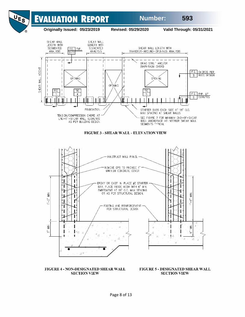
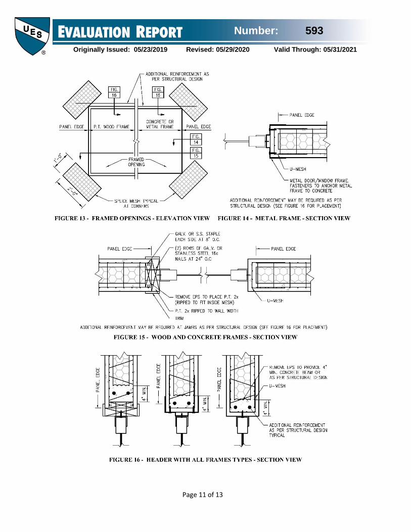
3.1.7 Openings: INNSTRUCT SMART
WALL/EVG-3D panels are permitted to have
openings. Figures 13 through 16 of this report
illustrate typical openings. A registered design
professional shall design the perforated wall systems
for openings. The horizontal wall segment above the
openings shall be designed for flexure, shear, and
deflection. Vertical wall segments adjacent to
openings shall be designed to support additional loads
from openings for axial compression, and out of plane
forces. The design shall comply with IBC® Chapter
19 and ACI 318-14.
3.1.8 Collector Elements: Collector Elements shall
be designed in accordance with ASCE/SEI 7-16 or -10
Section 12.10.2 incorporating Section 12.10.2.1 for
seismic force effects including overstrength.
3.2 Installation:
3.2.1 Panels: The INNSTRUCT Smart Wall/EVG-3D
panels shall be delivered, stored and handled in such a
manner that the insulation is not punctured, and the
welded-wire fabric is not deformed. On site, the
INNSTRUCT Smart Wall/EVG-3D panels shall be
erected/arranged adjacent to each other, in accordance
Number: 593
Originally Issued: 05/23/2019 Revised: 05/29/2020 Valid Through: 05/31/2021
Page 4 of 13
with the approved construction documents. WWR
and/or reinforcement is installed for structural
connection of the panels to each other and the
supporting structure. The joints between the panel EPS
cores shall be tightly closed and EPS core faces
aligned to be flush to ensure uniform thickness of
concrete or shotcrete over the whole panel and to avoid
thermal bridging. Small expansion spray foam can
also be used to close any joint gaps.
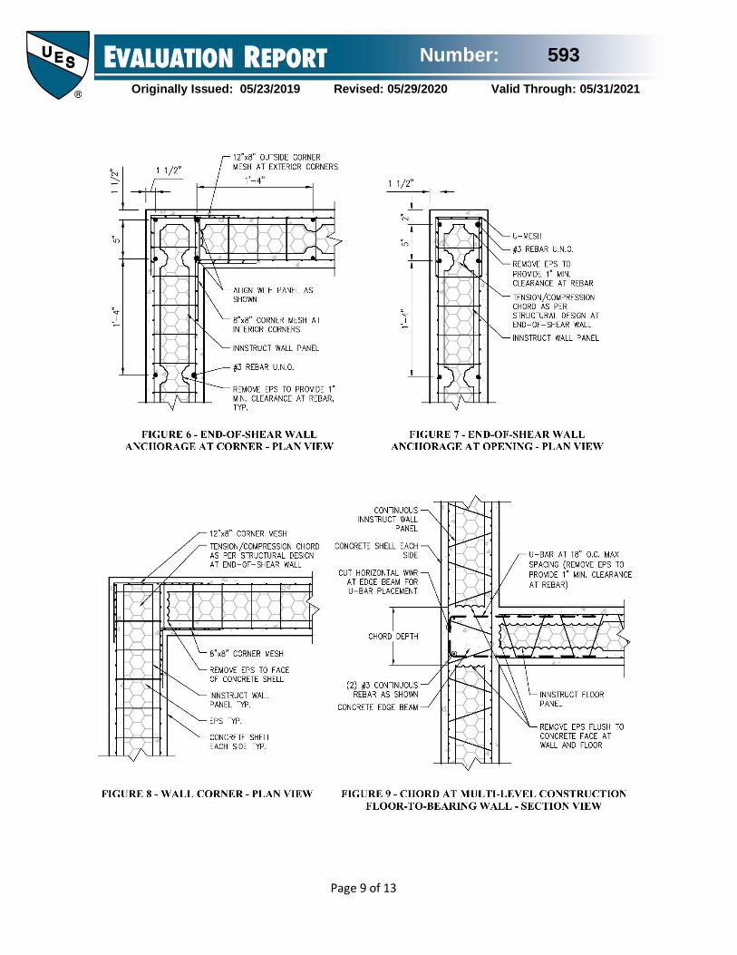
Vertical or horizontal, internal and external corners
formed between panels shall be reinforced with
welded wire reinforcement (WWR) attached to the
WWR sheets of the panels. Openings shall be
reinforced by placing WWR strips at a 45° angle near
corners. Additional WWR strips, bent into a U-Mesh,
shall be placed around doors, windows, and parapet
lintels. WWR strips bent into an inside or outside
corner mesh configuration are used to connect panels
at interior and exterior wall or roof intersections.
Figures 8 and 13 through 16 of this report provide
representative details.
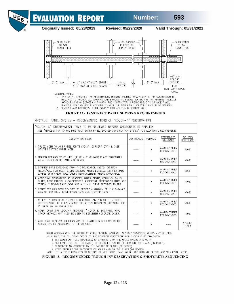
Panels shall be temporarily braced to ensure stability
and alignment, and to resist environmental forces
before the application of concrete or shotcrete. Floor
or roof panels shall be shored in accordance with
Figure 17 of this report prior to placement of shotcrete
or concrete.
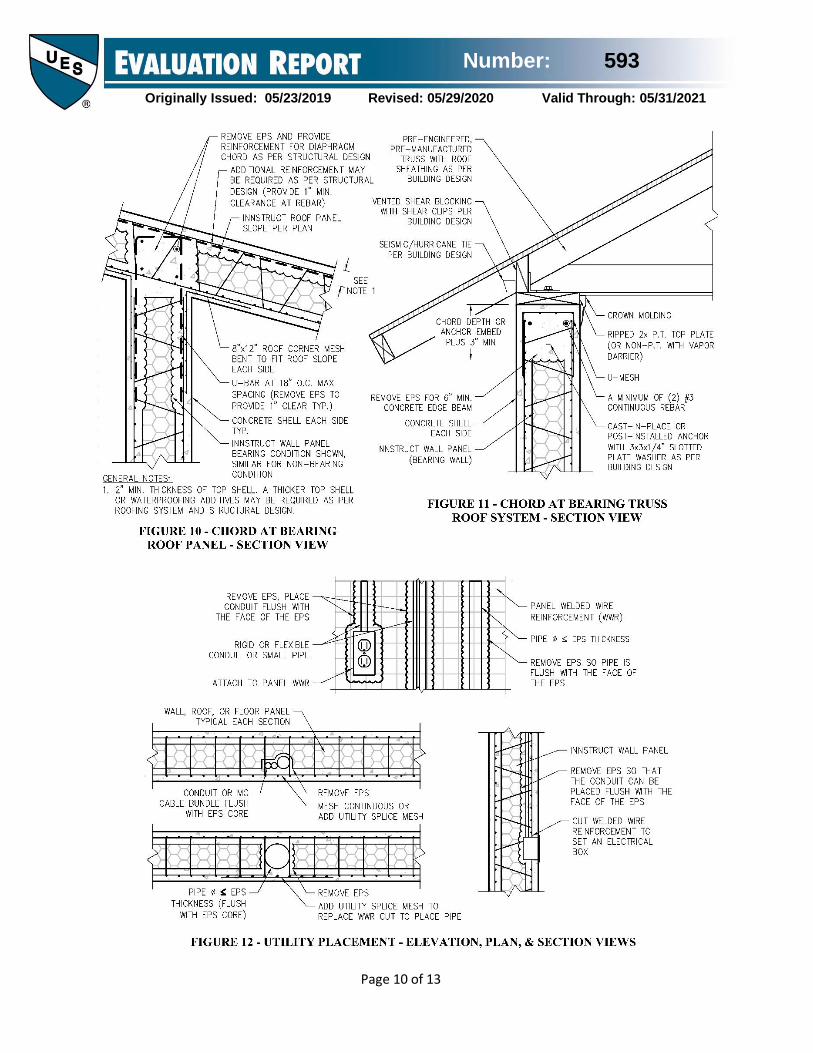
Rigid or flexible conduit and piping shall be placed by
removing EPS such that the conduit/pipe is flush with
the EPS. Metal clad cable (MC cable) having a
maximum diameter of ½ inch may be placed inside the
WWR in single runs. Bundled runs shall be set flush
with the face of the EPS. Electrical fixtures, plumbing
and other components shall be installed and secured in
accordance with the approved construction documents
and the building official or AHJ.
The interior and exterior finishes shall be applied as
described on the approved plans and in accordance
with the IBC®. Accent grooves or other linear
penetrations into the structural face are not permitted.
Evaluation of the finishes is beyond the scope of this
report.
3.2.2 Concrete Placement: Concrete shall be
placed on each side of the INNSTRUCT Smart
Wall/EVG-3D panel to the thickness given on the
approved construction documents, but no less than 2-
inches on each side of the panels. Concrete shall be
placed in accordance with IBC® Chapter 19, ACI 318-
14, and the manufacturer’s instructions. Where placed
in formwork for horizontal or vertical applications,
concrete shall be placed from the top. Concrete shall
be at least 2-inches thick on each side of the panels.
Formwork shall comply with ACI 318-14 Section
26.11. Concrete may be applied manually by hand or
by various pneumatic methods such as shotcrete (wet
or dry) in accordance with Section 3.2.3 of this report,
or pressurized plastering equipment.
3.2.3 Shotcrete Placement: Shotcrete shall be placed
on each side of the INNSTRUCT Smart Wall/EVG-
3D panel to the thickness given on the approved
construction documents, but no less than 2-inches on
each side of the panels. Shotcrete placement shall
comply with IBC® Section 1908, ACI 506.2-13, ACI
506.5-16, the manufacturer’s instructions, and
sequence specified in Figure 18 of this report.
3.2.4 Fire-resistance-rated Construction:
INNSTRUCT Smart Wall/EVG-3D panels, have fire
resistance ratings shown in Table 1 of this report.
3.3 Special Inspection: Special inspection shall
comply with 2018 and 2015 IBC® Sections 1704,
1705.3 and 1908, as applicable. The duties of the
special inspector include verification of compliance
with the approved construction documents, and this
report, including, but not limited to, welded-wire
reinforcement size, cover, and spacing; and
identification of INNSTRUCT Smart Wall/EVG-3D
panels in accordance with Section 7.0 of this report. In
addition, for shotcrete application, the duties of the
special inspector include verification of sampling and
preparation of test specimens, and conformance with
acceptance criteria in 2018 and 2015 IBC® Section
1908.10.3.
4.0 PRODUCT DESCRIPTION
4.1 General: The INNSTRUCT Smart Wall/ EVG-3D
panel consists of a three-dimensional grid of two
sheets of galvanized steel welded-wire reinforcement
(WWR), joined with diagonal connectors of
galvanized steel wire welded to the WWR; and a core
of expanded polystyrene (EPS) foam plastic
insulation, between the two WWR sheets, which is
Number: 593
Originally Issued: 05/23/2019 Revised: 05/29/2020 Valid Through: 05/31/2021
Page 5 of 13
penetrated by the connectors. The welded diagonal
connectors provide rigidity and shear transfer for
composite behavior. After the panels are erected into
position as wall, floor, or roof elements, shotcrete
and/or concrete is applied on both panel faces.
Additional reinforcement may be required for the
loading condition and where openings such as doors
and windows occur. The result is a composite
sandwich panel with two layers of concrete reinforced
by the WWR and with any additional reinforcing steel.
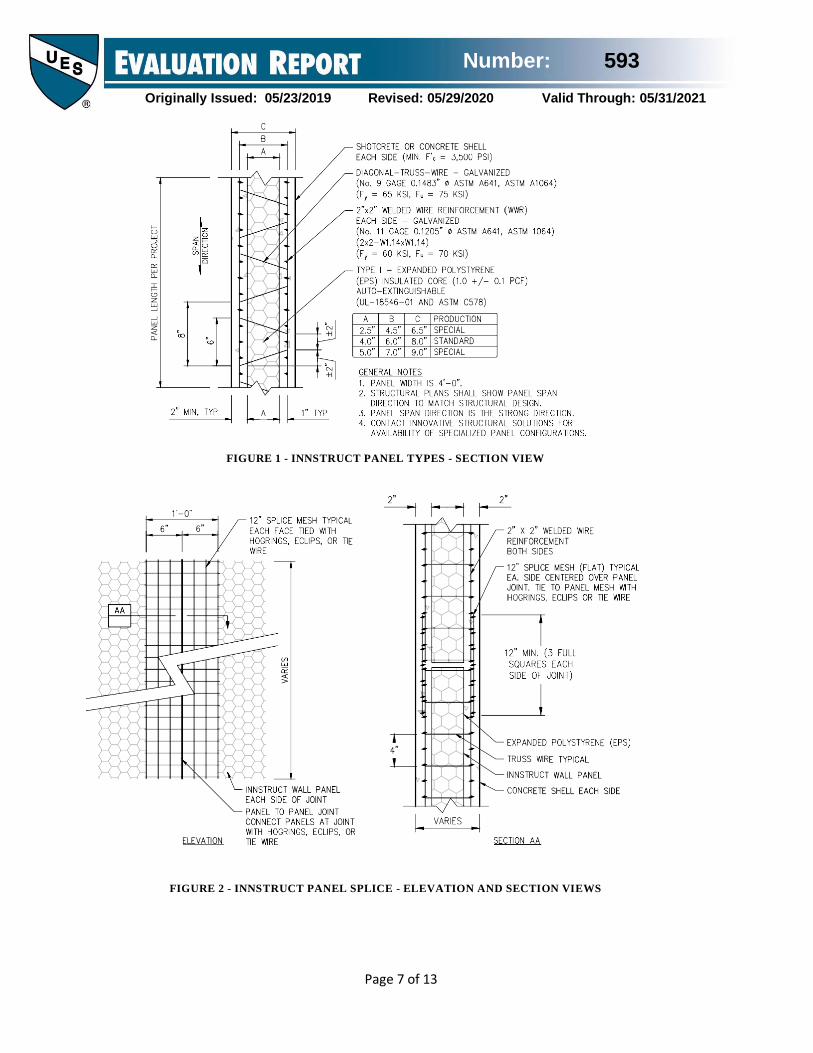
Figure 1 of this report describes possible panel types.
Figures 2 through 18 of this report illustrate certain
construction considerations. Details for the specific
project shall be provided on approved plans and
specifications
4.2 Materials:
4.2.1 Expanded Polystyrene (EPS) Foam Plastic:
EPS foam plastic insulation complying with UL-
18546-01 and ASTM C578 as Type I, with a 1 pcf
nominal density, forms the core. The EPS is
manufactured by producers recognized in the
approved quality documents. The EPS has a flame-
spread index of 25 or less and a smoke-developed
index of 450 or less to comply with ASTM E84 at a
maximum 5-inch thickness in conformance with IBC®
Section 2603.3.
4.2.2 Wire Reinforcement: The welded wire
reinforcement (WWR) and diagonal truss wires
comply with ASTM A1064 as plain wire with a Class
1 galvanized coating in accordance with ASTM A641.
The wire sizes for WWR are No. 11 gauge (0.1205-
inch) and for truss wires are No. 9 gauge (0.1483-
inch). The minimum specified yield and tensile
strengths are as follows: for the WWR (fy = 60,000 psi
and Fu = 70,000 psi) and for the diagonal truss wire (fy
= 65,000 psi and Fu = 75,000 psi). WWR sheets are
positioned one inch from the EPS Core, as shown in
Figure 1 of this report.
4.2.3 Reinforcing Bars: Deformed steel reinforcing
bars, shall comply with Section 20.2.1.3 of ACI 318-
14. The minimum specified yield strength, fy, is 60,000
psi.
4.2.4 Concrete: Normal weight Concrete is required
and shall comply with Chapter 19 of ACI 318-14. The
following additional requirements shall apply: 1)
maximum aggregate size shall comply with Section
26.4.2 of ACI 318-14: 2) maximum fresh concrete
slump is 4-inches; and 3) minimum specified
compressive strength, f´c, is 3,500 psi at 28 days.
4.2.5 Shotcrete: Shotcrete shall be of normal weight
concrete and comply with IBC® Section 1908. The
following additional requirements shall apply: 1)
maximum aggregate size is ⅜-inch; 2) aggregate
gradation shall be Gradation No. 1 in Table 1.1.1 of
ACI 506R-16; and 3) minimum compressive strength,
f´c, is 3,500 psi at 28 days.
5.0 IDENTIFICATION
For field identification, all packages of the delivered INNSTRUCT Smart Wall/EVG-3D panels covered by this report shall bear the name and trademark of the manufacturer (Innovative Structural Solutions, LLC), the evaluation report number (ER-593), and IAPMO UES Mark of Conformity. The face or edge of the insulation on each INNSTRUCT Smart Wall/EVG-3D panel shall be identified in accordance with IAPMO standards. Either Mark of Conformity may be used as shown below:
or
IAPMO UES ER-593
6.0 SUBSTANTIATING DATA
1. Data in accordance with the ICC-ES Acceptance
Criteria for Concrete Floor, Roof and Wall Systems
and Concrete Masonry Wall Systems (AC15) dated
February 2010.
2. Data in accordance with the ICC-ES Acceptance Criteria for Foam Plastic Insulation (AC12) dated June
2015, editorially revised October 2017.
3. Quality Control Manual and documentation of
compliance.
Number: 593
Originally Issued: 05/23/2019 Revised: 05/29/2020 Valid Through: 05/31/2021
Page 6 of 13
7.0 STATEMENT OF RECOGNITION
This evaluation report describes the results of research
carried out by IAPMO Uniform Evaluation Service on
Innovative Structural Solution Innstruct Smart
Wall/EVG-3D Panels to assess conformance to the
codes shown in Section 1.0 of this report and serves as documentation of the product certification. Products
are manufactured at the location noted in Section 2.10
of this report under a quality control program with
third-party inspections under the supervision of
IAPMO UES.
Brian Gerber, P.E., S.E.
Vice President, Technical Operations
Uniform Evaluation Service
Richard Beck, PE, CBO, MCP
Vice President, Uniform Evaluation Service
GP Russ Chaney
CEO, The IAPMO Group
For additional information about this evaluation report please
visit www.uniform-es.org or email us at [email protected]
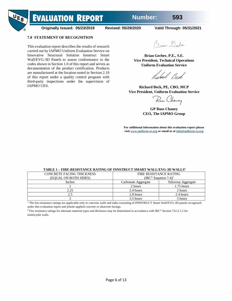
TABLE 1 – FIRE-RESISTANCE RATING OF INNSTRUCT SMART WALL/EVG-3D WALLS1
CONCRETE FACING THICKNESS (EQUAL ON BOTH SIDES)
FIRE RESISTANCE RATING (IBC® Equation 7-4)2
Inches Carbonate Aggregate Siliceous Aggregate
2 2 hours 1.75 hours
2.25 2.4 hours 2 hours
2.5 2.8 hours 2.4 hours
3 3.5 hours 3 hours 1 The fire-resistance ratings are applicable only to concrete walls and slabs consisting of INNSTRUCT Smart Wall/EVG-3D panels recognized
under this evaluation report and jobsite-applied concrete or shotcrete facings. 2 Fire resistance ratings for alternate material types and thickness may be determined in accordance with IBC® Section 722.2.1.2 for
multiwythe walls.
Number: 593
Originally Issued: 05/23/2019 Revised: 05/29/2020 Valid Through: 05/31/2021
Page 7 of 13
FIGURE 1 - INNSTRUCT PANEL TYPES - SECTION VIEW
FIGURE 2 - INNSTRUCT PANEL SPLICE - ELEVATION AND SECTION VIEWS
Number: 593
Originally Issued: 05/23/2019 Revised: 05/29/2020 Valid Through: 05/31/2021
Page 8 of 13
Number: 593
Originally Issued: 05/23/2019 Revised: 05/29/2020 Valid Through: 05/31/2021
Page 9 of 13
Number: 593
Originally Issued: 05/23/2019 Revised: 05/29/2020 Valid Through: 05/31/2021
Page 10 of 13
Number: 593
Originally Issued: 05/23/2019 Revised: 05/29/2020 Valid Through: 05/31/2021
Page 11 of 13
Number: 593
Originally Issued: 05/23/2019 Revised: 05/29/2020 Valid Through: 05/31/2021
Page 12 of 13
Number: 593
Originally Issued: 05/23/2019 Revised: 05/29/2020 Valid Through: 05/31/2021
Page 13 of 13
CALIFORNIA SUPPLEMENT
INNOVATIVE STRUCTURAL SOLUTIONS
375 EAST 400 NORTH
MORGAN, UTAH 84050
(801) 510-7770
http://www.innstruct.com
INNSTRUCT SMART WALL/EVG-3D PANELS
CSI Sections:
03 00 00 - CONCRETE
03 37 00 – Specialty Placed Concrete
1.0 EVALUATION SCOPE
The INNSTRUCT Smart Wall/EVG-3D panels
evaluated in IAPMO UES ER-593 comply with the
intent of the provisions of the following codes and
regulations:
• 2019 California Building Code (CBC)
• 2019 California Residential Code (CRC)
2.0 LIMITATIONS
The INNSTRUCT Smart Wall/EVG-3D panels,
described in this report, comply with the codes listed
in Section 1.0 of this supplement, subject to the
following limitations:
2.1 Provisions set forth in ER-593 for the 2018 IBC
and 2018 IRC shall apply, except as specifically noted in this supplement.
2.2 The limitations in Section 2.0 of ER-593 shall
apply.
2.3 For applications regulated by DSA or OSHPD,
construction documents shall comply with CBC
Section 1603A.
2.4 Inspections shall comply with CBC Chapter 17A
as applicable.
2.5 For applications regulated by DSA, applicable
provisions in CBC Section 1909 shall be observed.
2.6 For applications regulated by OSHPD, applicable
provisions in CBC Sections 1910 and 1911 shall be
observed.
2.7 For applications regulated by DSA or OSHPD,
material requirements and testing in Sections 1903A
and 1910A shall be observed.
2.7 For applications regulated by DSA or OSHPD,
design amendments in Section 1905A shall apply.
2.8 For applications regulated by DSA or OSHPD,
shotcrete shall comply with Section 1908A.
For additional information about this evaluation report please
visit www.uniform-es.org or email us at [email protected]


![One piece 593 [Mangas-wii.com]](https://img.pdfslide.us/doc/110x75/568c4a841a28ab4916987a14/one-piece-593-mangas-wiicom.jpg)