Embed Size (px)
Citation preview
Mereotopological description of product-processinformation and knowledge for PLM
Frederic Demoly1 ?, Aristeidis Matsokis2, Dimitris Kiritsis2, and SamuelGomes1
1 IRTES-M3M, UTBM, 90010 Belfort cedex, France{frederic.demoly,samuel.gomes}@utbm.fr
2 STI-IGR-LICP, EPFL, CH-1015 Lausanne, Switzerland{aristeidis.matsokis,dimitris.kiritsis}@epfl.ch
Abstract. This paper describes a description approach for modelingproduct-process information in the contexts of assembly oriented de-sign and product lifecycle management (PLM). The growing evolution ofmodels, methodologies, systems and tools over the entire product lifecy-cle has highlighted limits and difficulties – such as the awareness and un-derstanding in engineering – that did not exist before. An emergent chal-lenge remains in increasing awareness and understanding of actors in themanagement of product information and knowledge. This requires effortin new inspired approaches in the qualitative representation and reason-ing of the product and processes, in ontological applications, knowledge-based approaches, models, etc. The main objective is to make assemblyinformation consistent, accessible and exploitable by data managementsystems and computer-aided X tools by introducing a logical founda-tion. In this context, product-process relationships are considered anddescribed in the part-whole theory supported by mereology and its ex-tension, mereotopology, then implemented in an ontology.
Keywords: Product Lifecycle Management; Assembly modeling; On-tology; Mereotopology; Concurrent Engineering
1 Introduction
The growing evolution of models, methodologies, systems and tools over theentire product lifecycle has highlighted limits and difficulties – such as theawareness and understanding in engineering – that did not exist before. The2D drawings of the product and face-to-face discussions between lifecycle ac-tors have been revised for new way of working with people, tools, and manag-ing/representing information and knowledge. In such a context, some approachessuch as concurrent engineering, Design for X, 3D parametric design, ontology-based approaches, decision-making support, knowledge-based approaches, inte-grated data management have appeared to build the todays PLM strategy witha particular automation level, but an understanding layer is still missing. From
? Corresponding author.
2 Demoly et al.
a system and tool point of view, the traditional segmentation of the digitalchain – which includes CAD, CAE, PDM, ERP to name a few – has highlightedneeds in hub, bridge, dashboard applications in order to enable the continuityand relationship of product lifecycle phases, but still limited to point-to-pointinterface.
An emergent challenge remains in increasing awareness and understandingof actors in the management of product information and knowledge. Indeed, dueto the information overload (e.g. 3D large assembly model, multi-instances andparameters, etc.) this new way of working do not enable the full understanding ofthe lifecycle information and knowledge which is important in order to improveactors awareness and therefore quality in product lifecycle phases. This requireseffort in new inspired approaches in the qualitative representation and reason-ing of the product and processes, in ontological applications, knowledge-basedapproaches, models, etc.
The main objective is to make assembly information consistent, accessibleand exploitable by data management systems and computer-aided X tools byintroducing a logical foundation. Product information and knowledge as wellas the related assembly sequence require a logical framework in order to bemanaged consistently and processed proactively. As a consequence, product-process relationships are considered in the part-whole mathematical and philo-sophical theory supported by mereology and its extensions with topology suchas mereotopology primitives, theorems and axioms, and temporal relationships,then implemented in an ontology.
The paper briefly states, in section 2, the recent and relevant research workson assembly oriented design (AOD) approaches, assembly models and space-time mereotopological theories. In section 3, the proposed approach — calledPRONOIA3 (PROduct relatioNships description based On mereotopologIcAltheory) — for defining product relationships based on mereotopological theoryand temporal relationships is presented. Finally, in section 4, an ontologicalimplementation of PRONOIA by using Ontology Web Language - DescriptionLogic (OWL-DL) and Semantic Web Rule Language (SWRL) is described, inorder to demonstrate the application of such a qualitative description approachfor PLM systems.
2 Literature review
From a recent past, the issue of concurrent product design and ASP [2, 3] hasreceived much attention [4]. These efforts aimed at tackling difficulties and weak-nesses discovered in Design for Assembly (DFA) and ASP approaches by intro-ducing the concept of “Assembly-Oriented Design (AOD)” [2, 5]. The assemblyoriented practice in the product development can be seen as a top-down vision
3 PRONOIA was an Okaenid nymph of Mount Parnassos in Phokis (central Greece).She was the wife of the Titan Prometheus, and the goddess of foresight. Today thisword means forethought and provident care.
Mereotopological description for PLM 3
by proactively considering the assembly related product design and their rela-tionship issues in the early phases of the product development process. Thisemerging fashion highlights some challenges related to the recent shift in engi-neering design that promotes the relationships-based modelling and managementparadigm [6]. Current engineering requirements consist of closer integration ofproduct design and lifecycle models, better traceability on various abstractionlevels of the product (i.e. functional, behavioural, structural, geometric, techno-logical, etc.) and rational and consistent information management support withthe concept of “relational design”.
Based on this, recent assembly models relevant with the scope of the pa-per has been reported. Actually he significant growth of semantic value of in-formation and knowledge models during the last decade has highlighted newcontributions towards assembly semantic formalisms. Zha and Du promoted aknowledge-based system using multi-agent system and Petri Net to support as-sembly design and ASP by considering as input the part relational information[2]. Kim et al. proposed a spatial relationships-based assembly design formalismdescribing assembly relations, and an assembly model, in which relations arerepresented in XML format [9]. This work was only focused on the geometricaspect of the product and did not enable an efficient interpretation by CADtools. Recently, Kim et al. have tried to demonstrate the feasibility of an on-tological representation of assembly and associated constraints [10]. The sameauthors have proposed an ontology-based representation for assembly joints incollaborative product design by using mereotopological primitives and SWRLformalism [11]. Although this latter reported work is case study oriented, it canbe echoed here with the scope of the paper. More recently and based on a multi-view model MUVOA (Multiple Viewpoints Oriented Assembly) [8], Demoly etal. have described a product-process data management approach by introducingthe management of product relationships at various abstraction levels and inseparate manner [7].
Other relevant research works can also be considered, especially in the field offormal ontology, which is intended to be the support of the proposed approach.Mereotopology can be considered as a theory derived from mereology which isthe theory of part-whole relation [12]. Mereology enables the description of part-hood relation which is a reflexive, antisymmetric and transitive primitive. Anextension of this mathematical theory towards pointless topology is reportedby the mereotopology, which provides a further first-order logic description ofconnections between entities such as spatial regions [13, ?,?]. Indeed, instead offocusing on set theory, experience in product modelling and design has empha-sised on the need to work with a region-based theory by considering the productas it is perceived in the real world [16]. Built on this, many applications havebeen proposed: early product design stages [16], assembly joining technologies ofmechanical parts[11], four-dimensionalism [19] in oil and gas industry [20], etc.
A more complete survey of these research domains can be found in [21, 22].
4 Demoly et al.
3 Mereotopological product relationship descriptionapproach
In this section, the proposed PRONOIA approach is described. It enables thequalitative description of the product relationships at the beginning of the prod-uct design process by incorporating information related to the early-defined as-sembly sequence.
3.1 Basic mereotopology
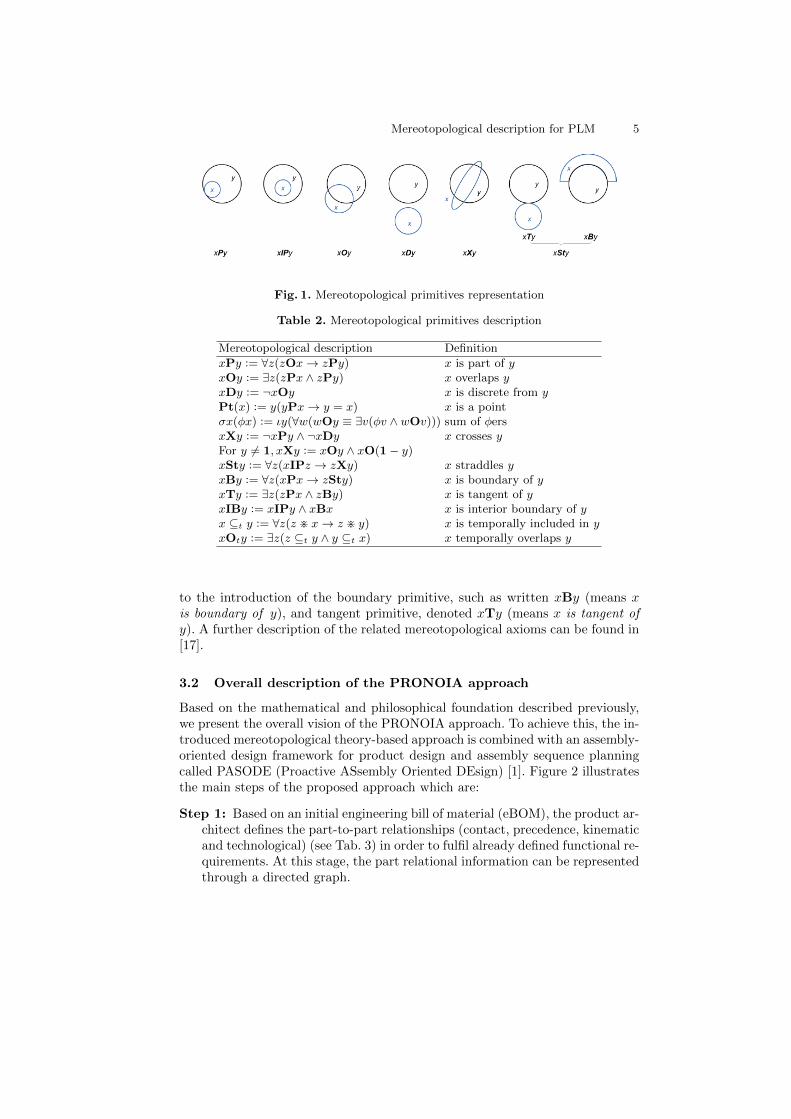
We introduce basic definitions of mereotopological primitives based on Smith’smereotopology [17], which are used as a starting point for the following sub-sections. Each primitive is written with a bold upper case between two entitiesas follows xRy, where R describes a particular relation between two entities,and variables x, y, z, etc. are ranged over entities. Table 1 presents operatorsand symbols used for the description of mereotopological primitives and tempo-ral relationships. All the mereotopological primitives described in this work areshown in Fig. 1 and Tab. 2.
Table 1. Fundamental mereotopological operators
Symbol Name Symbol Name
∨ Logical disjunction = Equality∧ Logical conjunction ≡ Equivalence→ Logical implication ¬ Logical negation∃ Existential quantifier ∀ Universal quantifierφ Condition ι Definite descriptorσ Sum (fusion or join) π General product:= Definition 6= Difference
Firstly, the mereological theory enables the description of the parthood rela-tion, where xPy means x is part of y and represents parthood for any applicationas shown in Fig. 1. Based on this primitive, other primitives can be further de-rived. Thus, the first derived mereological notion is that x overlaps y, denotedxOy, when z is any part of x and y. The second primitive is that x is discretefrom y, and is written xDy, this primitive means that x does not overlap y. Lastis the definition of x is a point, such as written Pt(x).
Mereotopological primitives can be introduced by considering topologicalmeans with the above described mereological primitives. A primitive derivedfrom P is that xIPy and means x is an interior part of y. Another one is thatx crosses y, and written xXy. This primitive means that x is neither a part ofy nor discrete from y. It also means that x overlaps both y and its complement(1 − y, with 1 stands for the Universe). The following primitive is x straddlesy, denoted xSty, and represents either a tangent or a boundary. Then it leads
Mereotopological description for PLM 5
Fig. 1. Mereotopological primitives representation
Table 2. Mereotopological primitives description
Mereotopological description Definition
xPy := ∀z(zOx→ zPy) x is part of yxOy := ∃z(zPx ∧ zPy) x overlaps yxDy := ¬xOy x is discrete from yPt(x) := y(yPx→ y = x) x is a pointσx(φx) := ιy(∀w(wOy ≡ ∃v(φv ∧ wOv))) sum of φersxXy := ¬xPy ∧ ¬xDy x crosses yFor y 6= 1, xXy := xOy ∧ xO(1− y)xSty := ∀z(xIPz → zXy) x straddles yxBy := ∀z(xPx→ zSty) x is boundary of yxTy := ∃z(zPx ∧ zBy) x is tangent of yxIBy := xIPy ∧ xBx x is interior boundary of yx ⊆t y := ∀z(z > x→ z > y) x is temporally included in yxOty := ∃z(z ⊆t y ∧ y ⊆t x) x temporally overlaps y
to the introduction of the boundary primitive, such as written xBy (means xis boundary of y), and tangent primitive, denoted xTy (means x is tangent ofy). A further description of the related mereotopological axioms can be found in[17].
3.2 Overall description of the PRONOIA approach
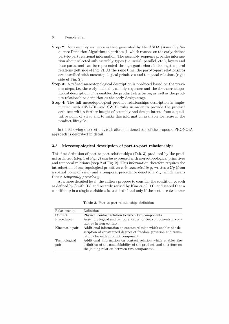
Based on the mathematical and philosophical foundation described previously,we present the overall vision of the PRONOIA approach. To achieve this, the in-troduced mereotopological theory-based approach is combined with an assembly-oriented design framework for product design and assembly sequence planningcalled PASODE (Proactive ASsembly Oriented DEsign) [1]. Figure 2 illustratesthe main steps of the proposed approach which are:
Step 1: Based on an initial engineering bill of material (eBOM), the product ar-chitect defines the part-to-part relationships (contact, precedence, kinematicand technological) (see Tab. 3) in order to fulfil already defined functional re-quirements. At this stage, the part relational information can be representedthrough a directed graph.
6 Demoly et al.
Step 2: An assembly sequence is then generated by the ASDA (Assembly Se-quence Definition Algorithm) algorithm [1] which reasons on the early-definedpart-to-part relational information. The assembly sequence provides informa-tion about selected sub-assembly types (i.e. serial, parallel, etc.), layers andbase parts, and can be represented through gantt chart including temporalrelations (left side of Fig. 2). At the same time, the part-to-part relationshipsare described with mereotopological primitives and temporal relations (rightside of Fig. 2).
Step 3: A refined mereotopological description is produced based on the previ-ous steps, i.e. the early-defined assembly sequence and the first mereotopo-logical description. This enables the product structuring as well as the prod-uct relationships definition at the early design stage.
Step 4: The full mereotopological product relationships description is imple-mented with OWL-DL and SWRL rules in order to provide the productarchitect with a further insight of assembly and design intents from a quali-tative point of view, and to make this information available for reuse in theproduct lifecycle.
In the following sub-sections, each aforementioned step of the proposed PRONOIAapproach is described in detail.
3.3 Mereotopological description of part-to-part relationships
This first definition of part-to-part relationships (Tab. 3) produced by the prod-uct architect (step 1 of Fig. 2) can be expressed with mereotopological primitivesand temporal relations (step 2 of Fig. 2). This information therefore requires theintroduction of one topological primitive: x is connected to y, written xCy (froma spatial point of view) and a temporal precedence denoted x / y, which meansthat x temporally precedes y.
At a more detailed level, the authors propose to consider the condition φ, suchas defined by Smith [17] and recently reused by Kim et al. [11], and stated that acondition φ in a single variable x is satisfied if and only if the sentence φx is true
Table 3. Part-to-part relationships definition
Relationship Definition
Contact Physical contact relation between two components.Precedence Assembly logical and temporal order for two components in con-
tact or in non-contact.Kinematic pair Additional information on contact relation which enables the de-
scription of constrained degrees of freedom (rotation and trans-lation) for each product component.
Technologicalpair
Additional information on contact relation which enables thedefinition of the assemblability of the product, and therefore onthe joining relation between two components.
Mereotopological description for PLM 7
Fig. 2. Mereotopological product relationships description approach (PRONOIA)
for at least one value of x. Hence the sum of φers can be defined as the entityy which is such that, given any entity w, w overlaps y if and only if w overlapswith something that φ, such denoted σx(φx) := ιy(∀w(wOy ≡ ∃v(φv ∧wOv))).
Based on this assumption, it is possible to introduce and define two entities(Fig. 3):
8 Demoly et al.
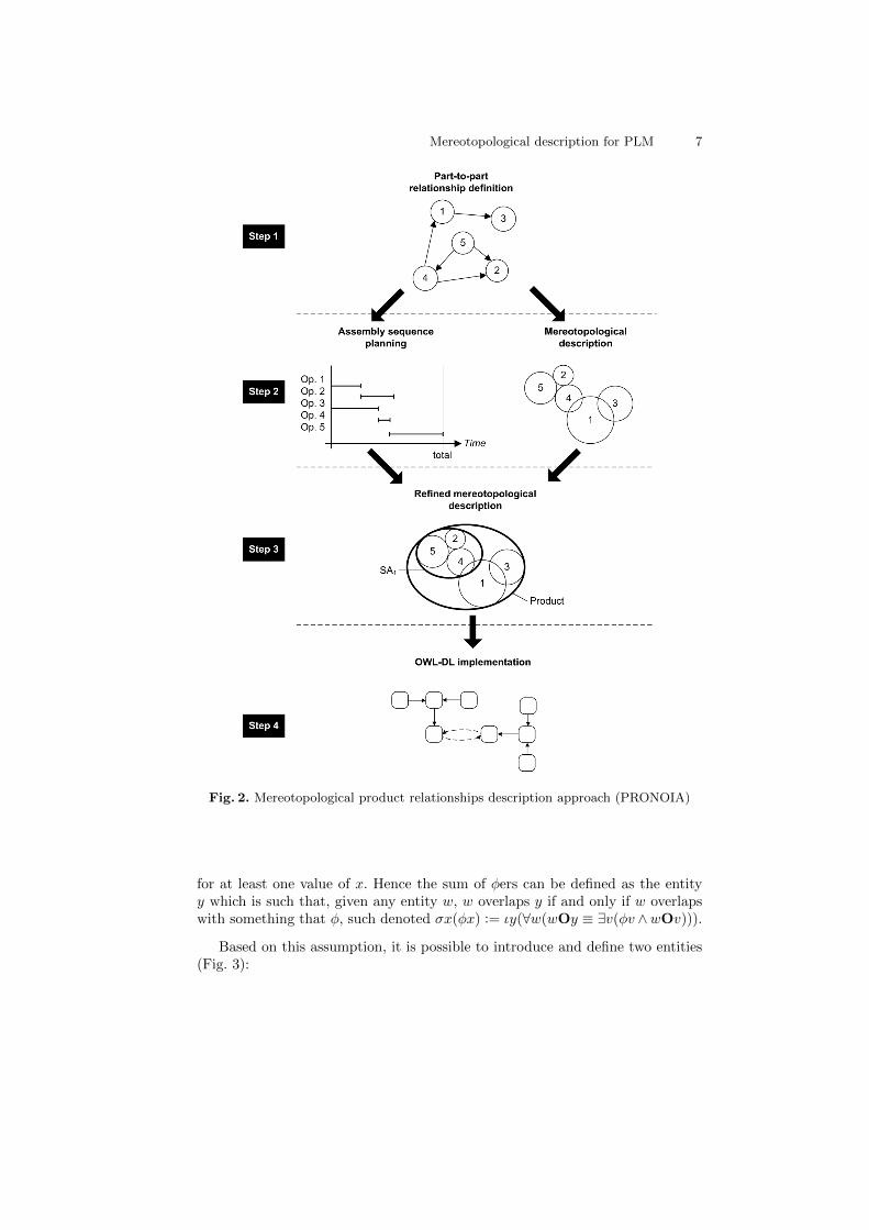
– k as any geometric skeleton entity for assembly positioning including point,line (also called straight), plane, curve of two product components x and y,and denoted k := σz(φz)→ ∀z(φz → (zTx ∧ zTy) ∧ (zPx ∧ zPy)).
– j as any geometric entity for mating boundary including point, line, plane,surface of two product components x and y, and denoted j := σz(φz) →∀z(φz → zBx ∧ zBy).
Fig. 3. Geometric representation of k a) and j b) entities
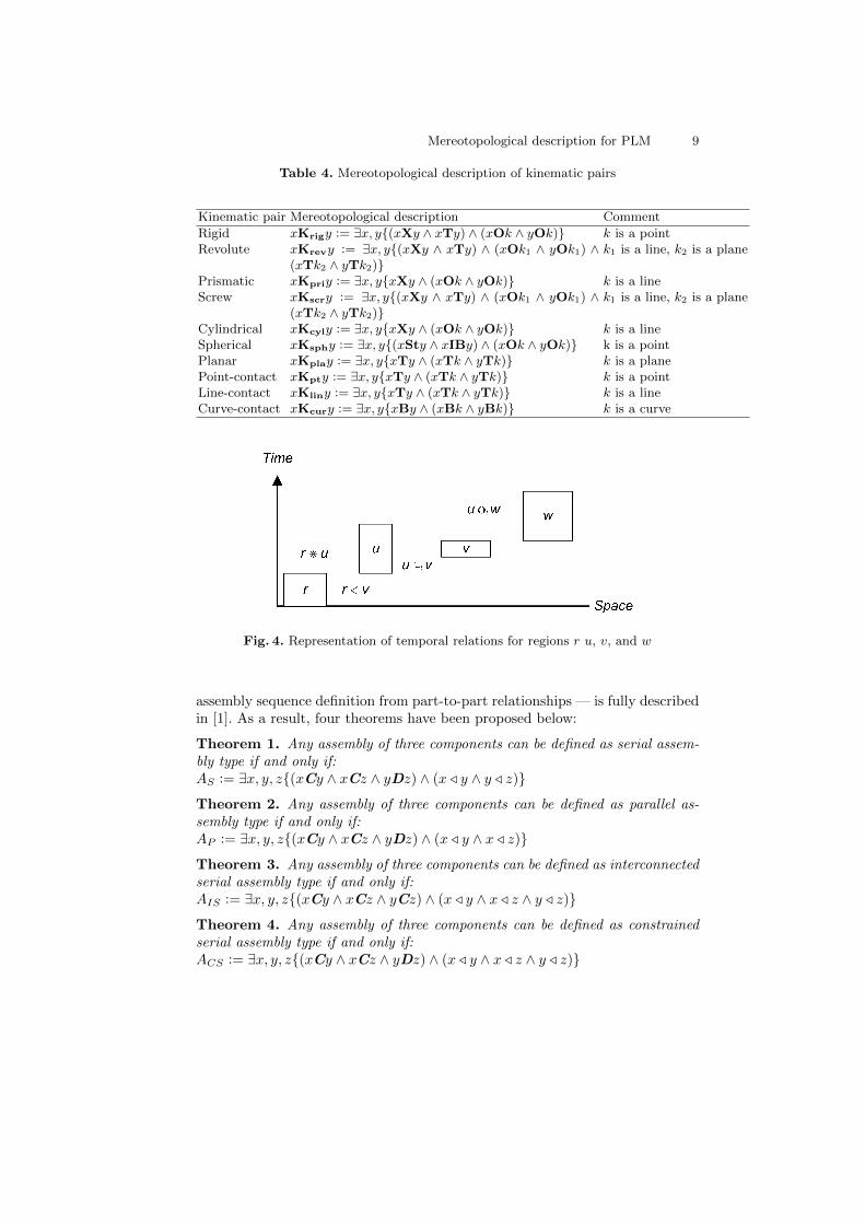
The entity k has been introduced to describe kinematic pairs, and j has beenreused from Kim et al. definition for technological pairs [11]. Table 4 presentsthe mereotopological description of kinematic pairs. The geometric skeleton kis used as a neutral element between two product components in contact forassembly synchronisation (e.g. CAD models of parts and sub-assemblies) at theassembly modeling and design stage. For instance, a revolute pair allows onlyone rotation between two parts, therefore introducing two geometric skeletons:a plane and a line (straight) that are together perpendicularly constrained.
3.4 Mereotopological description of assembly sequence
From a four-dimensionalism point of view, the consideration of temporal as-pect in mereotopology has led to the introduction of new primitives such asdescribed in [18, 19]. These primitives enable the definition of temporal relationsbetween spatial regions, especially the temporal inclusion (written ⊆t), the tem-poral overlaps (written Ot) and the temporal precedence (written /) based onthe temporal connection (written > ) as infix operators. Figure 4 shows therepresentation of these temporal relations in order to facilitate understanding.In this field, literature has provided theories by highlighting connection amongspatial, temporal, and spatio-temporal entities. However, only spatial regionsare considered as entities in this paper since the application field is focused onproduct engineering.
Based on this assumption, the aim is to propose a mereotopological descrip-tion of each sub-assembly type as described in [1], in order to build and describethe assembly sequence (steps 2-3 of Fig. 2). The ASDA algorithm — enabling the
Mereotopological description for PLM 9
Table 4. Mereotopological description of kinematic pairs
Kinematic pair Mereotopological description Comment
Rigid xKrigy := ∃x, y{(xXy ∧ xTy) ∧ (xOk ∧ yOk)} k is a pointRevolute xKrevy := ∃x, y{(xXy ∧ xTy) ∧ (xOk1 ∧ yOk1) ∧
(xTk2 ∧ yTk2)}k1 is a line, k2 is a plane
Prismatic xKpriy := ∃x, y{xXy ∧ (xOk ∧ yOk)} k is a lineScrew xKscry := ∃x, y{(xXy ∧ xTy) ∧ (xOk1 ∧ yOk1) ∧
(xTk2 ∧ yTk2)}k1 is a line, k2 is a plane
Cylindrical xKcyly := ∃x, y{xXy ∧ (xOk ∧ yOk)} k is a lineSpherical xKsphy := ∃x, y{(xSty ∧ xIBy) ∧ (xOk ∧ yOk)} k is a pointPlanar xKplay := ∃x, y{xTy ∧ (xTk ∧ yTk)} k is a planePoint-contact xKpty := ∃x, y{xTy ∧ (xTk ∧ yTk)} k is a pointLine-contact xKliny := ∃x, y{xTy ∧ (xTk ∧ yTk)} k is a lineCurve-contact xKcury := ∃x, y{xBy ∧ (xBk ∧ yBk)} k is a curve
Fig. 4. Representation of temporal relations for regions r u, v, and w
assembly sequence definition from part-to-part relationships — is fully describedin [1]. As a result, four theorems have been proposed below:
Theorem 1. Any assembly of three components can be defined as serial assem-bly type if and only if:AS := ∃x, y, z{(xCy ∧ xCz ∧ yDz) ∧ (x / y ∧ y / z)}
Theorem 2. Any assembly of three components can be defined as parallel as-sembly type if and only if:AP := ∃x, y, z{(xCy ∧ xCz ∧ yDz) ∧ (x / y ∧ x / z)}
Theorem 3. Any assembly of three components can be defined as interconnectedserial assembly type if and only if:AIS := ∃x, y, z{(xCy ∧ xCz ∧ yCz) ∧ (x / y ∧ x / z ∧ y / z)}
Theorem 4. Any assembly of three components can be defined as constrainedserial assembly type if and only if:ACS := ∃x, y, z{(xCy ∧ xCz ∧ yDz) ∧ (x / y ∧ x / z ∧ y / z)}
10 Demoly et al.
Built on this, the assembly sequence results from the concatenation of sub-assemblies descriptions including layers, and later on will influence the mereotopo-logical description of the product relationships.
4 OWL-DL implementation
This section describes the last step (step 4) of Fig. 2 whose aim is to reusethe relational information along the product lifecycle. In this work the authorsare defining an OWL-DL ontology information model. The concept behind de-veloping an OWL-DL ontology model was to implement ontology advantagesand features into the model which include: data structure layout, descriptionlogic (DL) [24] reasoning, semantic web rules including SWRL [25] and Jess ruleengine [26]. The use of the ontology combined with Description Logics (DLs)allows the authors to define/figure out: equivalencies of classes, consistency ofthe classes and make re-classification of the classes according to the conceptsthat they represent. Moreover, DLs are also used to infer/categorise instancesunder classes according to rules and requirements. Thus, the information sys-tem is executable, dynamic and flexible. In the rest of this work, the followingnaming conventions are used: names of classes are written in capitalised/lowercase Arial (i.e. Physical Product). Names of attributes and relationships are cap-italised /lower case Courier New (i.e. isParentOf) while names of instances arein italics Arial (i.e. Physical Part 1).
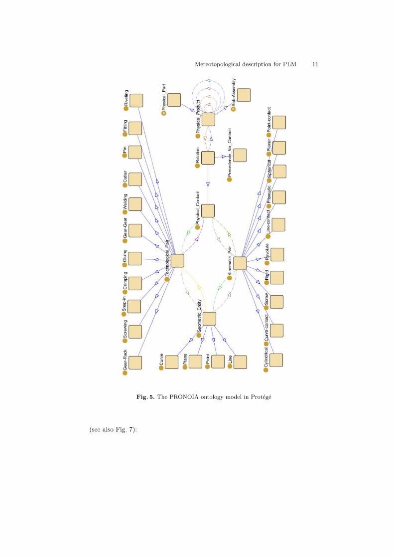
The authors focus on the information exchange between product design andassembly process phases. This is a part of the BOL information. The aim is tomake the information available along the product lifecycle. In order to describethe information in a generic and tangible manner, an ontology model has beendeveloped, which could be then used as a part of a model describing the entireproduct lifecycle. The proposed PRONOIA ontology model is shown in Fig. 5.The model has been developed to describe the assembly properties as they havebeen defined in mereotopology. It consists of the following main classes: Kine-matic Pair, Physical Contact, Relation, Physical Product, Technological Pair, Geo-metric Entity. These classes consist of several sub-classes which are also shown inFig. 5. The ontology model has been developed using the Protege ontology editor(Protege-OWL) and the classes have been defined using DL rules. The develop-ment process is the one described by Matsokis and Kiritsis [27]. The names ofthe relationships (objects properties) follow the Class Name2Class Name policy.
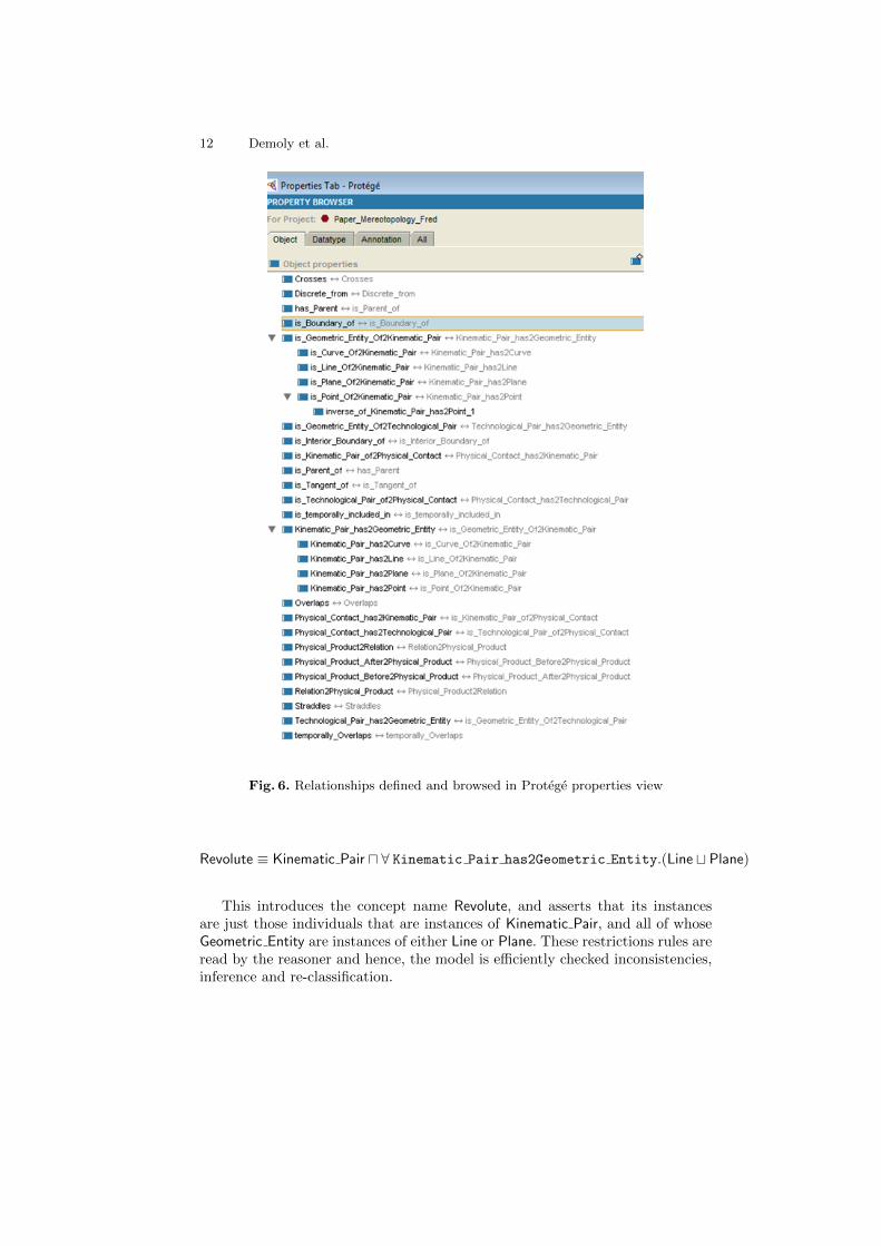
Fig. 6 shows the relationships between classes and those describing the mereotopo-logical primitives. DL rules (restrictions) have been defined in order to give alogical meaning to the classes and to make them understandable/readable forthe reasoner. The reasoner used in this case is Pellet 1.5.2 [28]. A comprehen-sive list of the added DL rules is presented in another paper [22]. Therefore, thereasoner can be used for supporting product architects by providing consistencycheck of the model, equivalencies among the classes, re-classification of the class-hierarchy and inference on the instances [29]. For example, the class Revolute ofthe PRONOIA model has the following restriction using standard DL notation
Mereotopological description for PLM 11
Fig. 5. The PRONOIA ontology model in Protege
(see also Fig. 7):
12 Demoly et al.
Fig. 6. Relationships defined and browsed in Protege properties view
Revolute ≡ Kinematic Pair u ∀ Kinematic Pair has2Geometric Entity.(Line t Plane)
This introduces the concept name Revolute, and asserts that its instancesare just those individuals that are instances of Kinematic Pair, and all of whoseGeometric Entity are instances of either Line or Plane. These restrictions rules areread by the reasoner and hence, the model is efficiently checked inconsistencies,inference and re-classification.
Mereotopological description for PLM 13
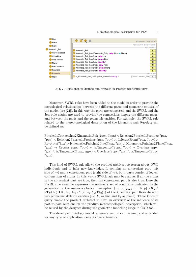
Fig. 7. Relationships defined and browsed in Protege properties view
Moreover, SWRL rules have been added to the model in order to provide themereological relationships between the different parts and geometric entities ofthe model (see [22]). In this way the parts are connected, and the SWRL and theJess rule engine are used to provide the connections among the different parts,and between the parts and the geometric entities. For example, the SWRL rulerelated to the mereotopological description of the kinematic pair Revolute canbe defined as:
Physical Contact has2Kinematic Pair(?pcx, ?kpx) ∧ Relation2Physical Product(?pcx,?ppx) ∧ Relation2Physical Product(?pcx, ?ppy) ∧ differentFrom(?ppx, ?ppy) ∧Revolute(?kpx) ∧Kinematic Pair has2Line(?kpx, ?glx) ∧Kinematic Pair has2Plane(?kpx,?gpx) → Crosses(?ppx, ?ppy) ∧ is Tangent of(?ppx, ?ppy) ∧ Overlaps(?ppx,?glx) ∧ is Tangent of(?ppx, ?gpx) ∧ Overlaps(?ppy, ?glx) ∧ is Tangent of(?ppy,?gpx)
This kind of SWRL rule allows the product architect to reason about OWLindividuals and to infer new knowledge. It contains an antecedent part (leftside of →) and a consequent part (right side of →), both parts consist of logicalconjunctions of atoms. In this way, a SWRL rule may be read as: if all the atomsin the antecedent part are true, then the consequent part is also true. Here theSWRL rule example expresses the necessary set of conditions dedicated to thegeneration of the mereotopological description (i.e. xKrevy := ∃x, y{(xXy ∧xTy) ∧ (xOk1 ∧ yOk1) ∧ (xTk2 ∧ yTk2)}) of the kinematic pair Revolute withtwo geometric skeleton entities (i.e. k1 as line and k2 as plane). These kinds ofquery enable the product architect to have an overview of the influence of itspart-to-part relations on the product mereotopological description, which willbe reused by the designer during the geometric modelling stage in CAD tool.
The developed ontology model is generic and it can be used and extendedfor any type of application using its characteristics.
14 Demoly et al.
5 Conclusion and future work
Following a much larger project in the field of assembly oriented design and PLM[1, 22], the proposed PRONOIA approach consists in the description of productrelationships from a qualitative point of view at the begining of the design pro-cess. This main objective has been covered with a large review of the literatureof the fields and still represents a huge challenge to tackle in order to providea new formal and machine-interpretable representation of AOD issue. Thus, theproposal has enabled the mereotopological description of product relationshipsat various abstraction levels, in order to provide a full insight and understand-ing of the product definition and assembly. The relationship-based modellingvision requires a qualitative description at the early stages of the product de-velopment process in order to promote a top-down and proactive support forproduct architects and designers. Moreover, an ontological implementation hasbeen introduced using OWL-DL and SWRL in order to represent formally theassembly information and enable its reuse in the other lifecycle phases. Futurework will address the application aspect of this theoretical basis, especially withan industrial case study in order to demonstrate its relevance in engineering.
References
1. Demoly, F., Yan X.-T., Eynard, B., Rivest, L. and Gomes, S., 2011. An Assembly-Oriented Design Framework for Product Structure Engineering and Assembly Se-quence Planning. Robotics and Computer-Integrated Manufacturing, 27(1), 33–46.
2. Zha, X.F. and Du, H., 2002. A PDES/STEP-based model and system for concur-rent integrated design and assembly planning. Computer-Aided Design, 34, 1087–1110.
3. Barnes, C.J., Jared, G.E.M. and Swift, K.G., 2004. Decision support for sequencegeneration in an assembly oriented design environment. Robotics and Computer-Integrated Manufacturing, 20, 289–300.
4. Wang, L., Keshavarzmanesh, S., Feng, H.Y. and Buchal, R.O., 2009. Assembly pro-cess planning and its future in collaborative manufacturing: a review. InternationalJournal of Advanced Manufacturing Technology, 41, 132–144.
5. Mantripragada, R., 1998. Assembly oriented design: concepts, algorithms and com-putational tools. PhD thesis, Massachussetts Institute of Technology.
6. Brown, J., 2006. Managing Product Relationships: Enabling Iteration and Innova-tion in Design. Business Value Research Series, June, AberdeenGroup.
7. Demoly, F., Yan, X.-T., Eynard, B., Kiritsis, D., and Gomes, S., 2011. Integratedproduct rela- tionships management: a model to enable concurrent product de-sign and assembly sequence planning, Journal of Engineering Design, Accepted,DOI:10.1080/09544828.2011.629317.
8. Demoly, F., Monticolo, D., Eynard, B., Rivest, L. and Gomes, S., 2010. Multipleviewpoint modelling framework enabling integrated product-process design. Inter-national Journal on Interactive Design and Manufacturing, 4(4), 269–280.
9. Kim, K.Y., Wang, Y., Muogboh, O.S. and Nnaji, B.O., 2004. Design formalism forcollaborative assembly design. Computer-Aided Design, 36(9), 849–871.
Mereotopological description for PLM 15
10. Kim, K.-Y., Manley, D.G. and Yang, H., 2006. Ontology-based assembly designand information sharing for collaborative product development. Computer-AidedDesign, 38, 1233–1250.
11. Kim, K.-Y., Yang, H., and Kim, D.W., 2008. Mereotopological assembly joint in-formation representation for collaborative product design. Robotics and Computer-Integrated Manufacturing, 24, 744–754.
12. Lesniewski, S., 1982. On the foundations of mathematics. Topoi 2, 7–52.13. Asher, N., and Vieu, L., 1995. Towards a geometry of common sense: A semantics
and a complete axiomatisation of mereotopology. In Proc. IJCAI-95, Montreal,Quebec, 846–852.
14. Varzi, A., 1996. Parts, wholes, and part-whole relations: The prospects ofmereotopology. Data and Knowledge Engineering, 20, 259–286.
15. Borgo, S., Guarino, N., and Masolo, C., 1996. A pointless theory of space based onstrong connection and congruence. In L. Aiello, J. Doyle, S.C. Shapiro (Eds.), Proc.Internat. Conference on Principles of Knowledge Representation and Reasoning(KR-96), Cambridge, MA, 220–229.
16. Salustri, F.A., 2002. Mereotopology for product modeling. A new framework forproduct modeling based on logic. Journal of Design Research, 2(1).
17. Smith, B., 1996. Mereotopology: a theory of parts and boundaries. Data andKnowledge Engineering, 20, 287–303.
18. Muller, P., 1998. A qualitative theory of motion based on spatio-temporal prim-itives. In A.G. Cohn, L. Schubert, and S. Shapiro (Eds.), Proceedings of KR-98,131-141.
19. Stell, J.G., and West, M., 2004. A 4-dimensionalist mereotopology. In A.C. Varzi,L. Vieu (Eds.), Proceedings of formal ontology in information systems, IOS Press,261–272.
20. ISO15926-2, 2003. Integration of lifecycle data for process plant including oil andgas production facilities: Part 2. Data model.
21. Demoly, F., Matsokis, A., and Kiritsis, D., 2011. A mereotopology-based approachfor integrated assembly modeling and planning. Proceedings of the ASME 2011International Design Engineering Technical Conferences & Computers and Infor-mation in Engineering Conferences, IDETC/CIE 2011, August 28-31, Washington,DC, USA.
22. Demoly, F., Matsokis, A., and Kiritsis, D., 2012. A mereotopological product rela-tionship description approach for assembly oriented design/ Robotics and ComputerIntegrated Manufacturing, 28(6), 681-693.
23. Demoly, F., Toussaint, L., Eynard, B., Kiritsis, D., and Gomes, S., 2011. Geomet-ric skeleton computation enabling concurrent product engineering and assemblysequence planning. Computer-Aided Design, 43(12), 1654-1673.
24. Baader, F., Calvanese, D., McGuinness, D., Nardi, D., and Patel-Schneider, P.F.,editors., 2003. The Description Logic Handbook: Theory, Implementation, andApplications. Cambridge University Press.
25. SWRL: A Semantic Web Rule Language Combining OWL and RuleML:http://www.w3.org/Submission/SWRL/. April 2011.
26. The Jess rule engine: http://herzberg.ca.sandia.gov/. April 2011.27. Matsokis, A., and Kiritsis, D., 2010. An ontology-based approach for Product Life-
cycle Management. Computers in Industry, 61(8), 787-797.28. Pellet Reasoner: http://clarkparsia.com/pellet/ Last accessed April 2011.29. Horrocks, I., 2007. Semantic Web: The story so far. ACM International Conference
Proceedings vol. 225, pp. 120-125, Proceedings of the 2007 international cross-disciplinary conference on Web accessibility (W4A), Banff, Canada.


![A Construction Approach of Model Transformation Rules ...dl.ifip.org/db/conf/ifip5-8/iwei2011/LiZNX11.pdf · transformation has been well achieved especially in database [3].Usually](https://img.pdfslide.us/doc/110x75/5f0d19747e708231d438acfd/a-construction-approach-of-model-transformation-rules-dlifiporgdbconfifip5-8iwei2011.jpg)