Embed Size (px)
Citation preview
Mercury Chamber Update
V. Graves
NF-IDS Meeting
October 4, 2011
2 Managed by UT-Battellefor the U.S. Department of Energy Mercury Chamber Update Oct 2011
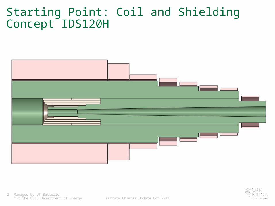
Starting Point: Coil and Shielding Concept IDS120H
3 Managed by UT-Battellefor the U.S. Department of Energy Mercury Chamber Update Oct 2011
Mercury Chamber Basics• Chamber serves as both jet and beam dumps
– Chamber must encompass the nozzle tip
• No openings into chamber during operation– Mercury flows in a closed loop
– Likely will be double-walled for mercury containment, possibly water cooled
• No embedded sensors
• Gravity drain of mercury required– Bulk flow exits chamber via overflow drain(s)
– Maintenance drain for beam-off operations
• Penetrations (ports) into chamber– Nozzle
– Hg drains (overflow and maintenance)
– Vents (in and out)
– Beam windows (upstream and downstream)
– Shell cooling?
4 Managed by UT-Battellefor the U.S. Department of Energy Mercury Chamber Update Oct 2011
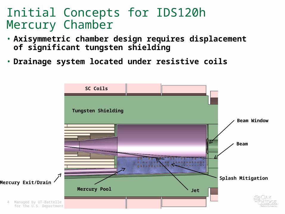
Initial Concepts for IDS120h Mercury Chamber• Axisymmetric chamber design requires displacement of significant tungsten
shielding
• Drainage system located under resistive coils
Beam
Jet
Splash Mitigation
Beam Window
Mercury Exit/Drain
Tungsten Shielding
Mercury Pool
SC Coils
5 Managed by UT-Battellefor the U.S. Department of Energy Mercury Chamber Update Oct 2011
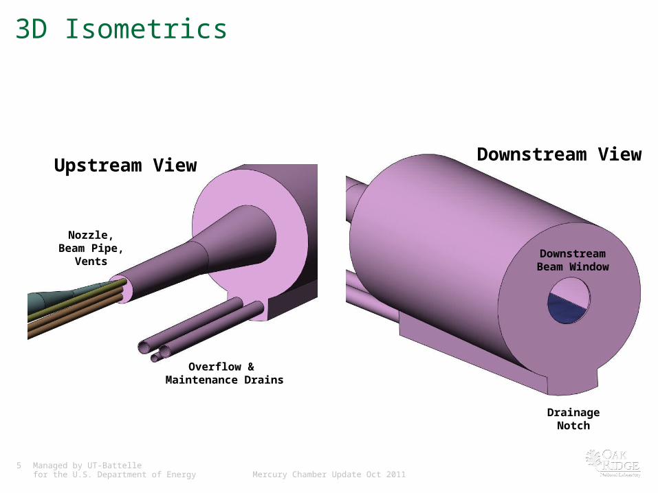
3D Isometrics
DownstreamBeam Window
DrainageNotch
Overflow & Maintenance Drains
Nozzle,Beam Pipe,
Vents
Upstream View Downstream View
6 Managed by UT-Battellefor the U.S. Department of Energy Mercury Chamber Update Oct 2011
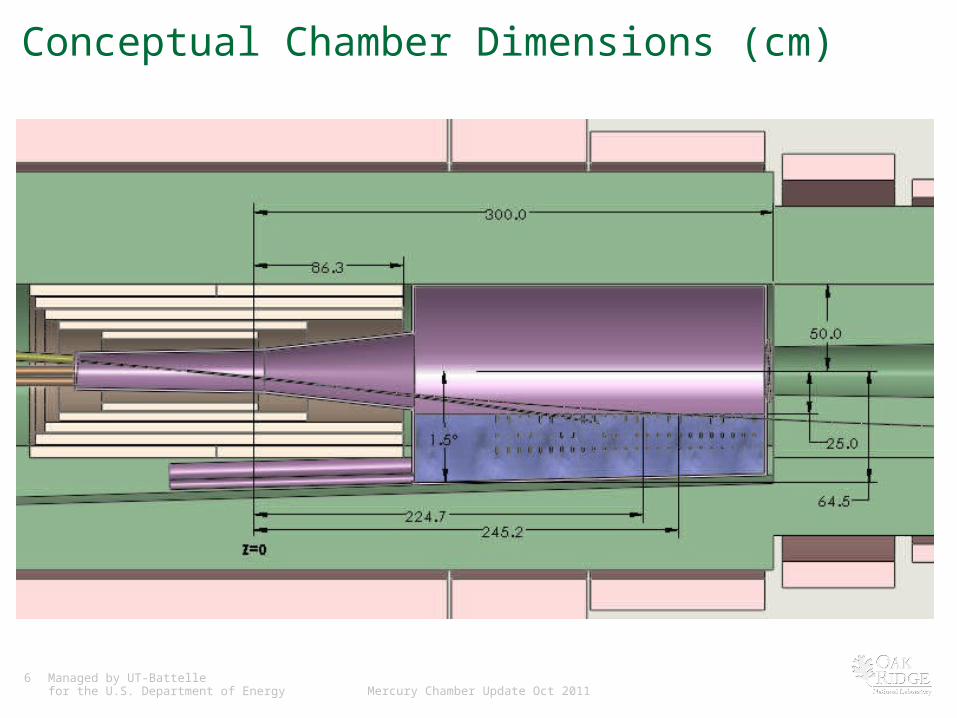
Conceptual Chamber Dimensions (cm)
7 Managed by UT-Battellefor the U.S. Department of Energy Mercury Chamber Update Oct 2011
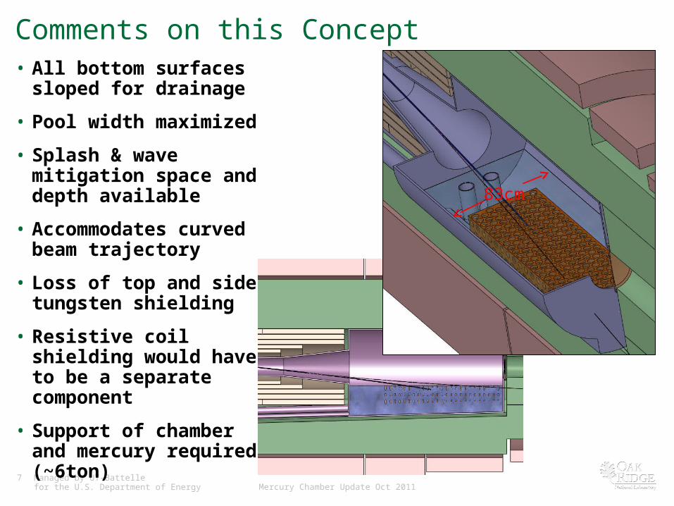
Comments on this Concept• All bottom surfaces sloped for
drainage
• Pool width maximized
• Splash & wave mitigation space and depth available
• Accommodates curved beam trajectory
• Loss of top and side tungsten shielding
• Resistive coil shielding would have to be a separate component
• Support of chamber and mercury required (~6ton)
83cm
8 Managed by UT-Battellefor the U.S. Department of Energy Mercury Chamber Update Oct 2011
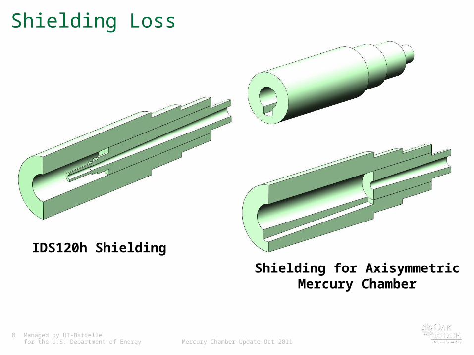
Shielding Loss
IDS120h Shielding
Shielding for AxisymmetricMercury Chamber
9 Managed by UT-Battellefor the U.S. Department of Energy Mercury Chamber Update Oct 2011
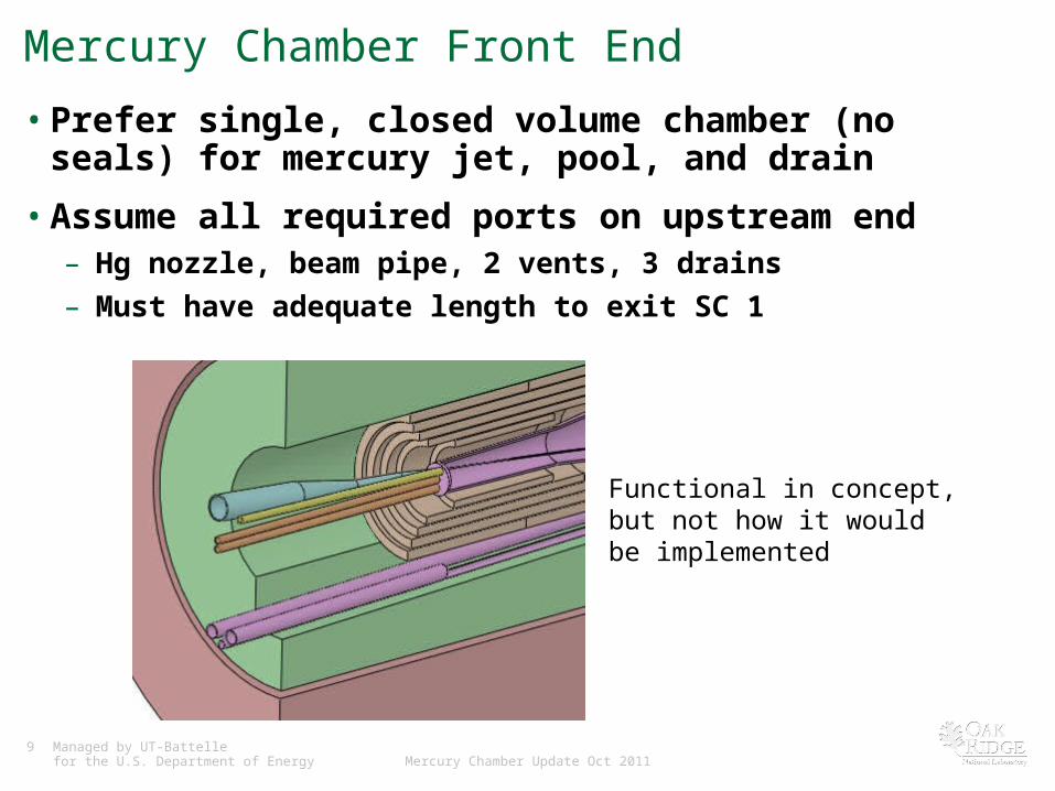
Mercury Chamber Front End
• Prefer single, closed volume chamber (no seals) for mercury jet, pool, and drain
• Assume all required ports on upstream end– Hg nozzle, beam pipe, 2 vents, 3 drains
– Must have adequate length to exit SC 1
Functional in concept, but not how it would be implemented
10 Managed by UT-Battellefor the U.S. Department of Energy Mercury Chamber Update Oct 2011
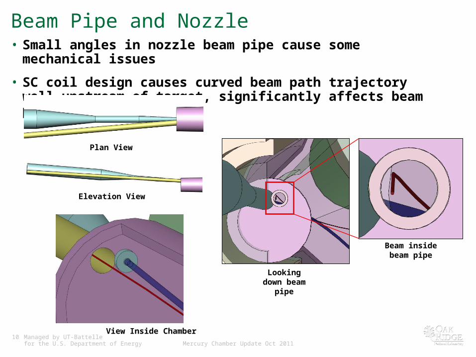
Beam Pipe and Nozzle• Small angles in nozzle beam pipe cause some mechanical issues
• SC coil design causes curved beam path trajectory well upstream of target, significantly affects beam pipe
Plan View
Elevation View
View Inside Chamber
Looking down beam pipe
Beam inside beam pipe
11 Managed by UT-Battellefor the U.S. Department of Energy Mercury Chamber Update Oct 2011
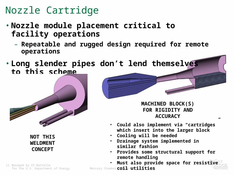
Nozzle Cartridge
• Nozzle module placement critical to facility operations– Repeatable and rugged design required for remote operations
• Long slender pipes don’t lend themselves to this scheme
NOT THIS WELDMENT
CONCEPT
MACHINED BLOCK(S) FOR RIGIDITY AND ACCURACY
• Could also implement via “cartridges” which insert into the larger block
• Cooling will be needed• Drainage system implemented in similar fashion• Provides some structural support for remote handling• Must also provide space for resistive coil utilities
12 Managed by UT-Battellefor the U.S. Department of Energy Mercury Chamber Update Oct 2011
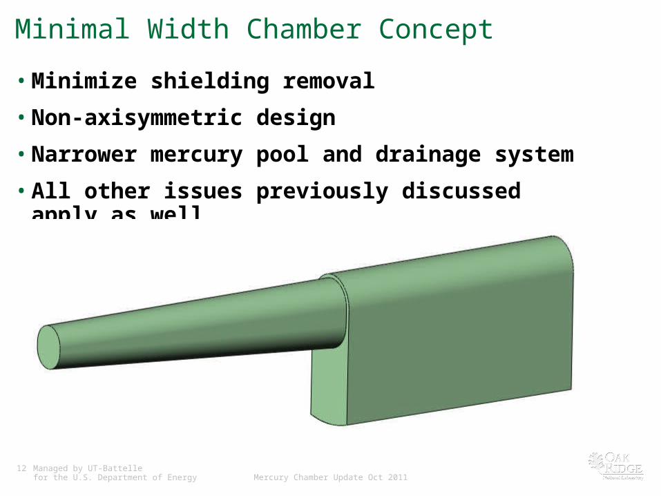
Minimal Width Chamber Concept
• Minimize shielding removal
• Non-axisymmetric design
• Narrower mercury pool and drainage system
• All other issues previously discussed apply as well
13 Managed by UT-Battellefor the U.S. Department of Energy Mercury Chamber Update Oct 2011
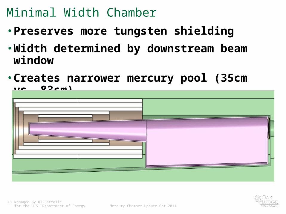
Minimal Width Chamber
• Preserves more tungsten shielding
• Width determined by downstream beam window
• Creates narrower mercury pool (35cm vs. 83cm)– Wave / splash mitigation issues, beam stopping
14 Managed by UT-Battellefor the U.S. Department of Energy Mercury Chamber Update Oct 2011
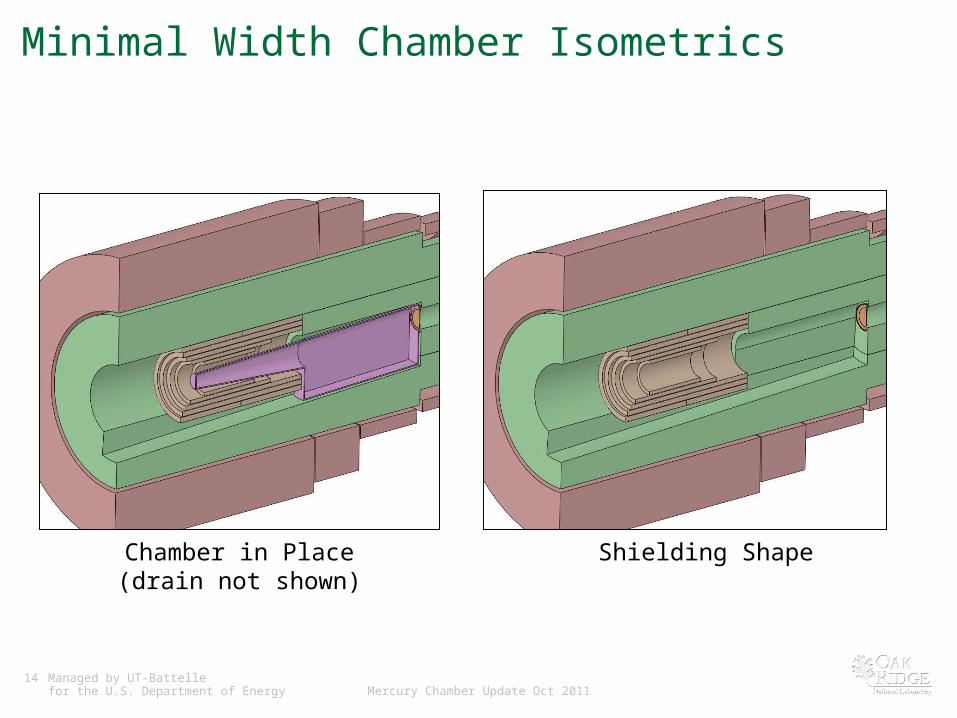
Minimal Width Chamber Isometrics
Shielding ShapeChamber in Place(drain not shown)

15 Managed by UT-Battellefor the U.S. Department of Energy Mercury Chamber Update Oct 2011
Manufacturing
• Hg chamber encompass hourglass-shaped resistive magnets
• Very complex geometry, tight positional placement required
• Machine where possible, minimize welding
• Insert portion of chamber through magnets, weld downstream components
• Will have to handle chamber and coils as a single module
16 Managed by UT-Battellefor the U.S. Department of Energy Mercury Chamber Update Oct 2011
Some Engineering Issues
• Means of vertical support
• Double-wall mercury containment– Chamber wall(s) cooling
• Beam pipe and nozzle mechanical layout
• Shielding resistive coils
• Long upstream magnets– More difficult remote handling for inner components– Affects proton beam trajectory well before it impacts target

17 Managed by UT-Battellefor the U.S. Department of Energy Mercury Chamber Update Oct 2011
Mercury Chamber Wish List
• Eliminate resistive coils
• Enlarge resistive coils such that a cylindrical mercury chamber can be pulled through them
• If above not possible, then an integrated coil/chamber design required
• Minimize coil length of all upstream magnets