Embed Size (px)
Citation preview

Status of the Neutrino Factory Accelerator Design Studies
Gersende Prior (CERN)on behalf of the
EUROnu and IDS-NFcollaborations
NUFACT’11 CERN & Geneva University 04 August 2011
March 2011: publication of the Interim Design Report (IDR), documenting in details the Neutrino Factory Design Study:
https://www.ids-nf.org/wiki/FrontPage/Documentation/IDR
134 authors, 47 Institutes:

3
Plan
The Neutrino Factory: wish-list and constraints
Proton driver & annexes CERN SPL-based scenario Fermilab (upgrade to Project X) scheme RAL (upgrade to ISIS) scenario
Target system Hg-jet target developments alternative/mitigation options
Front-end system Front end status alternative/mitigation cooling options
Muon acceleration linac and RLA’s FFAG ring decay rings
From the IDR to the RDR

4
NF Wish-list & Constraints
We want a machine capable of: performing precision measurement of the last unknown mixing angle 13. search for CP-invariance violation in neutrino oscillations. determine the sign of m2
31.
measure all the oscillation parameters with an unprecedented precision.
It requires an intense (4 MW, 1021 /year), high-energy (> 20 GeV) neutrino and anti-neutrino beams. Therefore putting the following constraints on the target & accelerator systems:
the target should be able to withstand beam-induced shocks. the muon beam should be bunched (allow both muon signs transport in
different RF buckets), rotated (reducing the energy spread) and cooled (reduction of the beam emittance) over a small distance.
a rapid muon acceleration system able to transport the muons beam to two decay rings with minimum beam losses.
The feasibility study will determine: if we can overcome its technical challenges. the cost driving factors & risk mitigation solutions.
The neutrino factory feasibility study is on the road toward muon colliders.
V. Shiltsev “Toward a Muon Collider” (Friday – Plenary)
ISS design

5
Proton driver & annexes status (1/3)
CERN SPL-based proton driver: H- linac. bunch frequency 352.2 MHz. repetition rate 50 Hz. high-speed chopper < 2ns (including rise & fall times).
Option 1: 2.25 MW (2.5 GeV) or 4.5 MW (5 GeV). 1.1 x 10¹⁴ protons/pulse. average pulse current 20 mA. pulse duration 0.9 ms.
Option 2: 5 MW (2.5 GeV) and 4 MW (5 GeV). 2 x 10¹⁴ protons/pulse (2.5 GeV) and 1 x 10¹⁴ protons/pulse (5 GeV). average pulse current 40 mA. pulse duration 1 ms (2.5 GeV) and 0.4 ms (5 GeV).
Progress: beam instabilities studies in the accumulator investigated for 3 bunches. accumulator & compressor rings MADX lattice available for 3 bunches case. starting to list accumulator & compressor rings elements for the costing.
R. Garoby “Proton drivers for Neutrino Beams…” (Friday – plenary)
ISS design

6
Proton driver & annexes status (2/3)
Fermilab Project X-upgrade-based proton driver, 4 MW at 8 GeV: increase the CW linac average current to 5 mA. need to increase pulsed linac duty factor to ~10% (Project X is ~5%). need to increase number of particles per linac bunch. add an accumulator ring. add a compressor ring.
Accumulator: ~250 m circumference. 14 bunches ~100 ns long. 1.3 x 10¹³ protons/bunch. stripping with foil or laser.
Compressor: at entrance ~50 ns bunches. debunch in ~ few ns bunches.
Challenges & tasks: stripping foil survival or lasertechnique demonstration. instabilities/space charge studies. beam size and angle at target optimization.
ISS designProject X layout
& upgrade
accumulator+compressor
5 mA

7
Proton driver & annexes status (3/3)
Upgrade of the Rutherford Appleton Lab (RAL), ISIS (neutron spallation source) to provide beam powers of 2-5 MW in the few GeV energy range.
Could be shared between a short pulse-spallation neutron source and the Neutrino Factory.
Would require an additional RCS or FFAG booster in order to: bring the proton beam to the necessary energy perform appropriate bunch compression
Current studies: lattice and high-intensity studies for a ~3.3 GeV booster synchrotron and
beam lines 800 MeV high-intensity linac design RCS and FFAG lattice studies for a main ring accelerator
R&D needs: high-power front-end(FETS) RF systems stripping foils diagnostics kickers
ISS design
Current ISIS with TS1 & TS2
Planned 0.8-3.2 GeV RCS and a new TS3
Planned 800 MeV H- linac
3.2-6.4 (9.6) GeV RCS for the NF and the NF-TS

8
Target systems (1/2)
Hg-jet target scheme: muon capture in 20 T solenoid followed by an adiabatic taper to 1.5 T.
Previous design (IDR): simulations (MARS15 & FLUKA) results showing high levels of energy deposition in
the magnets (~2.4 MW need to be dissipated in the shielding). both the Hg-jet and proton beam disrupt the Hg pool (need splash mitigation).
Redesign: better shielding of the SC magnets from radiation splash mitigation being handled. mechanical support under improvement.
R&D: MERIT (2007) validated 4 MW proton beam operation in Hg.
Target tasks: define target station infrastructure, including outer shielding, remote handling, Hg
cooling loop, beam windows and beam dump.
K. McDonald “Simulation of Dynamic Interaction of…” (Wednesday – Parallel)K. McDonald “Multi-MW target and capture design for NF” (Thursday- Plenary)
ISS design

9
Target systems (2/2)
Alternative target systems under consideration: a metal-powder-jet a system of solid tungsten bars that are exchanged between beam pulses
Metal-powder-jet: test rig at RAL with 100 kg W powder (grain size < 250 m) ~20 min continuous operation. coherent free flow jet P ~ 2 bars. validation of results with simulations.
Solid target: shock study using high-currents in thin W (Ta) wires. results in agreement with LS-DYNA simulations. preliminary target change system engineering underway.
Future R&D: flow improvement with mitigation of flux breakdown orphase separation for the powder target. irradiation study for tungsten powder and tungsten pebblebed at the CERN HiRadMat facility.
C. Densham “Target options for NF” (Wednesday – Parallel)
ISS design

10
Front-end status
Revised (IDR) lattice optimization - need to get rid earlyof unwanted particles:
proton absorber for low-momentum protons. chicane for high-momentum particles. transverse collimation.
Started to take the reference lattice parameters for: engineering study costing exercise
Remaining tasks: determine realistic operational RF gradient limits (R&D @MTA). assess and mitigate energy deposition from particle losses. optimize lattice matching sections. develop engineering design for magnets, RF and absorbers.
K. Yonehara “Commissioning and status of the MTA…” (Wednesday – Parallel)
D. Neuffer “Neutrino Factory Front-end…” (Thursday – Parallel)

11
Alternative cooling lattices (1/3)
The RF cavities sit in high (9-16 MV/m) magnetic field increasing the risk of breakdown as suggested by experiments performed at the Muon Test Area (MTA) at Fermilab.
Three alternative scenarios are under study as alternative to the breakdown problem.
bucked coil lattice magnetically insulated lattice HPRF lattice
bucked coil lattice: reduced magnetic field in the RF. 1.80 m or 2.10 m long cell. different current configurations. 2 cooling cells simulation in G4MICE. tested with both reduced (1000 muons) and fullstatistics.
-> good transmission in comparison with the ISS lattice.
A. Alekou “ Performance comparison between FS2A…“ (Wednesday – Parallel)
ISS design

12
Alternative cooling lattices (2/3)
Magnetically insulated lattice: E B field in cavity similar performance to the ISS lattice tested E to B angle at the MTA.
-> tolerance to coil misalignement <2 mm.-> multipactoring & power consumption issues to address.
Buncher/Rotator cell
Cooling cellD. Stratakis et al., PRSTAB 14, 011001 (2011)

13
Alternative cooling lattice (3/3)
HPRF lattice (M. Zisman/J. Gallardo): cavity filled with high-pressure H2 gas use LiH absorbers for muon cooling study of windows material study of pressure and windows thickness
-> tests with a gas-filled cavity were doneat the MTA.
M. Zisman “Accelerator for Future Neutrino…”
(Monday – Plenary)

14
Acceleration system: linac and RLAs
Acceleration system: need to start by a linac for low-energies (below 0.9 GeV). followed by two RLAs allowing multiple passes (to 12.6 GeV). final acceleration to 25 GeV in FFAG.
Linac: short (3 m, 3.8 MV/m), medium (5 m, 5.1 MV/m) and long (8 m, 6.4 Mv/m) cells
made of SC RF and solenoids. focusing with solenoids (better for low-energy, large emittance beams). increase acceleration rate by moving toward crest.
RLAs: dogbone shape provide greater separation at switchyard (over racetrack). made of SC RF and quadrupoles. inject into linac center. 4.5 passes per linac.
Linac & RLAs task: validation of the switchyard design. complete lattice design (matching sections, injection, overall layout). track through all subsystems with realistic errors. complete the engineering design for all the components (magnets, RF…).
K. Beard “ Linac & RLA design status and simulations” (Thursday – Parallel)
ISS design

15
Acceleration systems: FFAG
Linear non-scaling FFAG: single arc with large energy acceptance. consists entirely of identical FDF triplets. almost all drifts contain SC cavities or injection/extraction hardware.
Injection/Extraction: kickers shared for both muons signs. inject from inside/extract to outside. slightly bigger magnet apertures in injection/extraction
regions.
FFAG tasks: finalize the chromatic correction scheme. determine optimal longitudinal phase space matching. design matching to upstream and downstream systems. complete 6D tracking with errors. design main components (magnets, RF, injection/extraction). make cost comparison with equivalent RLA solution.
J. Pasternak “Recent development on the…” (Thursday – Parallel)
ISS design

16
Decay rings (1/2)
Design criteria: two (one per detector) racetrack shaped rings. 3 x train 0f ~50 bunches, 25 GeV. muons decay in straight which is a large fraction of the
circumference. store both muon signs simultaneously. beam divergence from the lattice at most 0.1/. 1609 m circumference, 599 m straights. tilt angles of 36 (7500 km detector) and 18 (4000 km
detector). depths of 440 m and 240 m respectively. is 150 m in the straights and 13 m in the arcs.

17
Decay rings (2/2)
Beam diagnostics: polarimeter to measure decay electrons
use g-2 muon spin precession high-precision beam energy measurement gives also the energy spread
divergence measurement with in-beam devices cherenkov with He gas optical transition radiation (OTR) device
-> challenging to get to the desired precision level (natural 1/ is 4 mrad).
Decay rings task: design the injection system. assess needs for chromatic corrections and beam abort scheme. design study of diagnostics and specifications (polarimeter, OTR…). consider whether beam abort is necessary. design means to measure neutrino flux spectrum at far detectors.
A. Blondel “Neutrino flux monitoring in the NF” (Tuesday – Parallel)

18
From the IDR to the RDR
Review of the Neutrino Factory design study: The European Committee for Future Accelerators (ECFA)
Review Panel was mandated to review the EUROnu Mid-term Report and the IDS-NF Interim Design Report (IDR).
Review meeting at STFC, Daresbury May 5-6, 2011.
Review will be presented in a written report (available soon), a report summary that will be given to the CERN council, and was presented at the ECFA-EPS joint session (Grenoble, 23 July 2011).
Steps toward the Reference Design Report (RDR): develop a complete and technically feasible design having
the required performance. carry out the end to end tracking of the entire facility to
validate performance estimate. perform a cost estimate for the whole facility.
Goal is to publish the RDR by the end of 2012/13.
~514 days left until December
31, 2012.
A big THANKS for the help providing material for this
presentation to my EUROnu & IDS-NF colleagues:
A. Alekou, C. Ankenbrandt, J. Back, S. Berg, N. Charitonidis, R. Garoby, K. Gollwitzer, K. Long, K. McDonald, D. Neuffer, J. Pasternak, C. Rogers,
D. Stratakis, J. Thomason, M. Zisman…

BACKUPSLIDES

IDS-NF and EUROnu structures:
EUROnu
SB BB
NF
The Americas Canada
USA
Asia Japan
India
(in the future: China …)
Europe EUROnu
IDS-NF
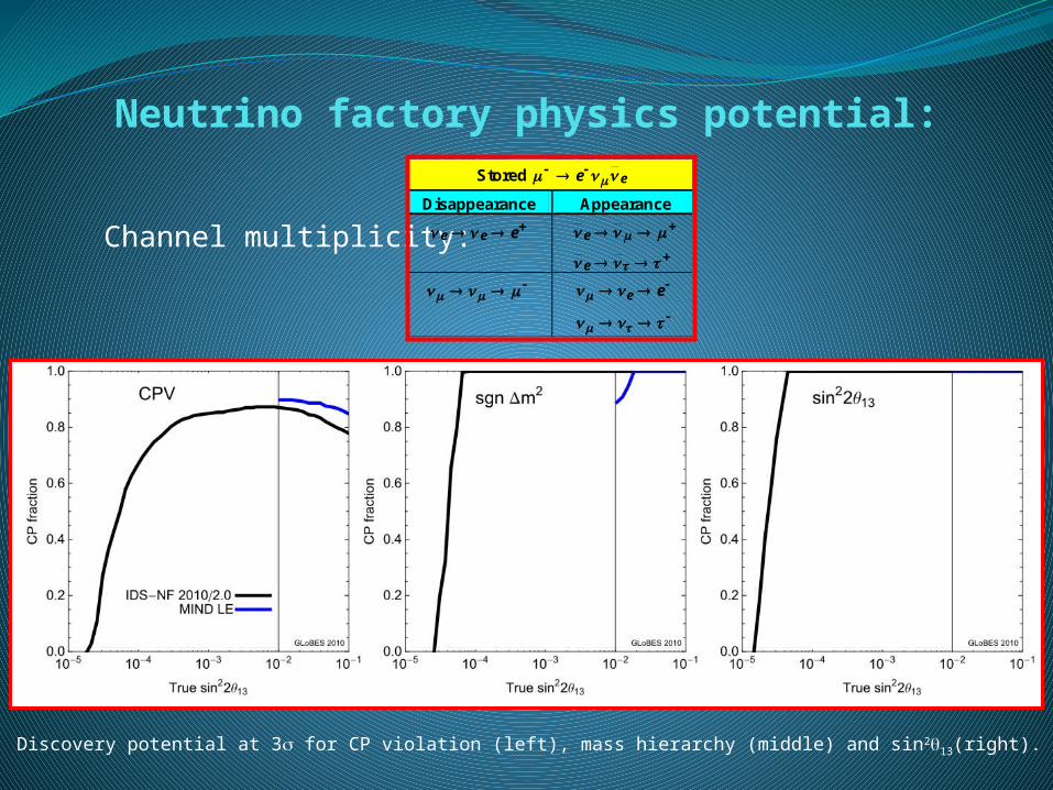
Neutrino factory physics potential:
Discovery potential at 3 for CP violation (left), mass hierarchy (middle) and sin213(right).
Channel multiplicity:
Stored ee
Disappearance Appearance eee
e
e
ee


![2 arXiv:1105.4077v2 [hep-ph] 30 Jan 2013 · 2018. 10. 31. · arXiv:1105.4077v2 [hep-ph] 30 Jan 2013 CERN-PH-TH/2011-118, EURONU-WP6-11-35, IFIC/11-24, MPP-2011-56 Neutrino Probesof](https://img.pdfslide.us/doc/110x75/60b3eb4cdb6f5a1ee173f9da/2-arxiv11054077v2-hep-ph-30-jan-2013-2018-10-31-arxiv11054077v2-hep-ph.jpg)