Embed Size (px)
Citation preview
Mentor Graphics Tutorial This document is intended to assist ECE Students taking ECE-331, Digital Systems Design, ECE-332, Digital Design Lab, ECE-445, Computer Organization, and ECE-545, Introduction to VHDL, in setting up their computing environment for using Mentor Graphics tools on cpe02.gmu.edu. It also contains a basic tutorial for running VHDL simulations using the ModelSim software. The Mentor Graphics software is designed to operate in an X-terminal environment on unix workstations. MGC is currently installed on cpe02.gmu.edu. This means that MGC software can be accessed from the X-terminals in Room 133 of S&T-II as well as from other on/off-campus X-terminals (e.g., Linux ssh) or under MS-Windows using the X-windows emulator Cygnus XFree86 (via gmu ftp) . All MS-Windows machines available in the ECE Departmental Labs located in S&T II, rooms 203 and 265, as well as S&T I, rooms 2A and 2B have this X-terminal emulator installed on them. To start this terminal and connect to cpe02 simply click on the cpe02 icon visible on the desktop in the top-left corner of the screen. Please, keep in mind that an off-campus access over a dial-up connection is less than satisfactory in either environment, although suitable performance may be possible through a DSL or Cable-Modem connection.
Initial Setup Specific Instructions for setting up your computing environment on cpe02.gmu.edu: 1. Log in to cpe02 using the username and password given to you in class. 2. Open the Workspace Menu by clicking with right mouse button anywhere on the desktop, go
to the Tools menu and click on Terminal. The terminal window will open with the user@dab:path> prompt inside. The user part of the prompt shows your user name, and path - your current directory.
3. Prepare the "working" directory by typing
initvsim
at the prompt. This command will create the directory mgc_work and copy example files to this directory. Note: This step should only be performed once, otherwise your directory (and work) will be reinitialized.

ModelSim Start-up You are now ready to start the ModelSim software and run a sample VHDL simulation. 1. At the prompt type
cd mgc_work
to change your working directory. Note: Always start ModelSim from this directory. Otherwise, the software may have difficulty finding and modifying files.
2. At the prompt type
vsim & to start the ModelSim software. Note: The “&” causes the command to run in the background, keeping the UNIX prompt available for further commands.
3. Upon opening ModelSim for the first time, you will see a Welcome to ModelSim dialog box. (If this screen is not available, you can enable it by selecting Help > Enable Welcome from the Main window. It will then display the next time you start ModelSim.)
By clicking the “Always open last project” radio button, you can skip this screen and proceed directly to your project.
4. To create a “Project” to organize all your laboratory work, click the “Create a Project” button.

In the “Create a New Project” dialog box, select the “Create a new project from scratch” radio button, then click the “Browse” button to select the New Project’s Home.
Simply click “OK” to create the new project directory in your “mgc_work” directory (where you started ModelSim).

Next, type in ece332_labs (or other appropriate name) in the “New Project Name” box.
Selecting OK causes the project directory to be created with a default working library. In the dialog box that asks if you want to create a new HDL source file for your project, click No.
5. Finally, to open your new project and begin work, select it from the pull-down menu arrow to the right of the “Open Project” button and text box.
Then, click “Open Project” (or “Done”) in the Welcome to ModelSim dialog box. Now you are ready to begin editing your VHDL source code and compiling your project for simulation.
Creating/Editing VHDL Files There are several ways to create/edit VHDL source files prior to compilation and simulation: • Use the Notepad editor from within ModelSim • Create the files outside of ModelSim and “Import” them into your project
• Use a UNIX editor like vi, emacs, or pico • Use an external text editor and upload/download the files to cpe02
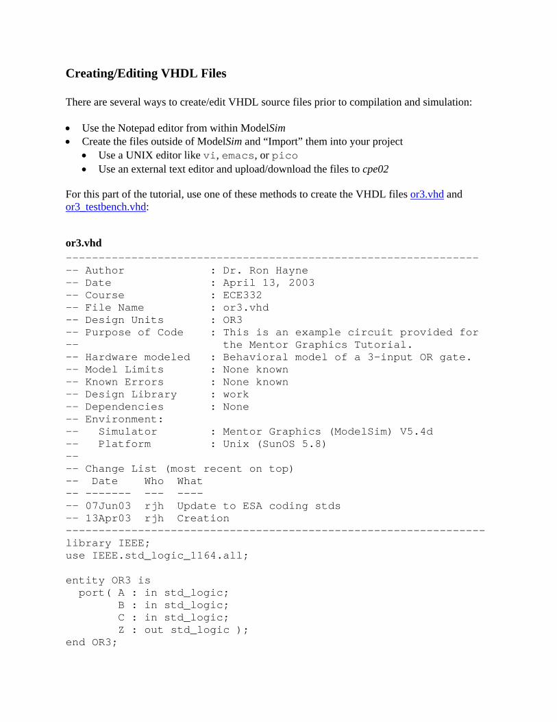
For this part of the tutorial, use one of these methods to create the VHDL files or3.vhd and or3_testbench.vhd:
or3.vhd --------------------------------------------------------------- -- Author : Dr. Ron Hayne -- Date : April 13, 2003 -- Course : ECE332 -- File Name : or3.vhd -- Design Units : OR3 -- Purpose of Code : This is an example circuit provided for -- the Mentor Graphics Tutorial. -- Hardware modeled : Behavioral model of a 3-input OR gate. -- Model Limits : None known -- Known Errors : None known -- Design Library : work -- Dependencies : None -- Environment: -- Simulator : Mentor Graphics (ModelSim) V5.4d -- Platform : Unix (SunOS 5.8) -- -- Change List (most recent on top) -- Date Who What -- ------- --- ---- -- 07Jun03 rjh Update to ESA coding stds -- 13Apr03 rjh Creation ---------------------------------------------------------------- library IEEE; use IEEE.std_logic_1164.all; entity OR3 is port( A : in std_logic; B : in std_logic; C : in std_logic; Z : out std_logic ); end OR3;

--------------------------------------------- architecture BEHAVE of OR3 is begin Z <= A or B or C after 10 ns; end BEHAVE;
or3_test_bench.vhd --------------------------------------------------------------- -- Author : Dr. Ron Hayne -- Date : May 26, 2003 -- Course : ECE332 -- File Name : or3_testbench.vhd -- Design Units : OR3_Testbench -- Purpose of Code : This is a top level testbench for the OR3 -- example which is provided for the Mentor -- Graphics Tutorial. -- Hardware modeled : This testbench creates an instance of the -- OR3 circuit and then drives the inputs -- and checks the results. -- Model Limits : VHDL-93 Syntax (report) -- Known Errors : None known -- Design Library : work -- Dependencies : OR3 -- Environment: -- Simulator : Mentor Graphics (ModelSim) V5.4d -- Platform : Unix (SunOS 5.8) -- -- Change List (most recent on top) -- Date Who What -- ------- --- ---- -- 07Jun03 rjh Update to ESA coding stds -- 26May03 rjh Creation --------------------------------------------------------------- library IEEE; use IEEE.std_logic_1164.all; use IEEE.std_logic_unsigned.all; entity OR3_Testbench is end OR3_Testbench;

architecture Testbench of OR3_Testbench is signal Input: std_logic_vector(2 downto 0) := "000"; signal Z : std_logic; component OR3 port( A : in std_logic; B : in std_logic; C : in std_logic; Z : out std_logic ); end component; begin -- Component Instantiation Tested_Circuit : OR3 port map( A => Input(2), B => Input(1), C => Input(0), Z => Z ); -- Cycle through test vectors and evaluate the results process begin wait for 100 ns; case Input is when "000" => assert (Z = '0') report "Test Failed"; when others => assert (Z = '1') report "Test Failed"; end case; Input <= Input + "001"; end process; end Testbench;

Notepad Editor 1. From the ModelSim main window, select File > New > New Source
and enter the name of the file you want to create.
2. You can now use the Notepad editor to create/edit your VHDL source code.
Importing VHDL source files 1. Create VHDL files in your project directory, $HOME/mgc_home/ece332_labs/
• Create/edit the files using a UNIX editor OR
• Use a web browser of ftp program to download/upload the files to cpe02
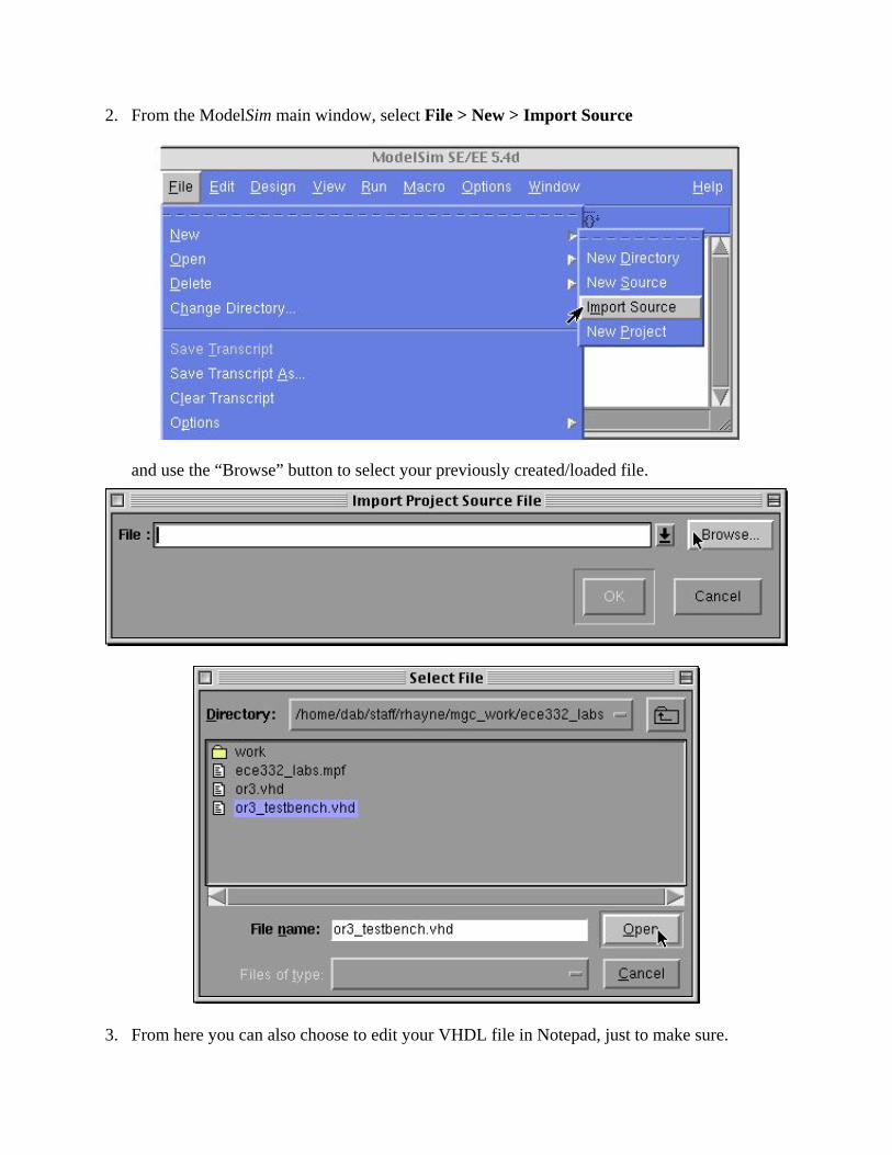
2. From the ModelSim main window, select File > New > Import Source
and use the “Browse” button to select your previously created/loaded file.
3. From here you can also choose to edit your VHDL file in Notepad, just to make sure.

Editing Your Project At any time while using ModelSim, you can create or import new VHDL files, edit existing files, as well as compile them by selecting Options > Edit Project from the main window.

Compiling and Simulating VHDL 1. Compile the file or3.vhd into your work library using the Compile button on the toolbar
or
by selecting Design > Compile from the main ModelSim window.
a transcript of the compile operation is shown in the main ModelSim window.

2. Next, you need to compile the file or3_testbench.vhd (which contains VHDL-93 syntax)
into your work library. Before compiling, you need to set the Default Options for the compiler to Use 1993 Language Syntax.
This only needs to be done once, since these compiler options will be retained unless reset.

3. Now, its time to load the design unit using the Load Design button from the toolbar or
by selecting Design > Load Design from the main ModelSim window.
Note: Load the or3_testbench entity, since this is what drives the simulation and provides the test vectors to the or3 entity.
4. Once the design is loaded, use the View menu in the main ModelSim window to open the
following windows to be used in this simulation:
• Source • Signals • Wave
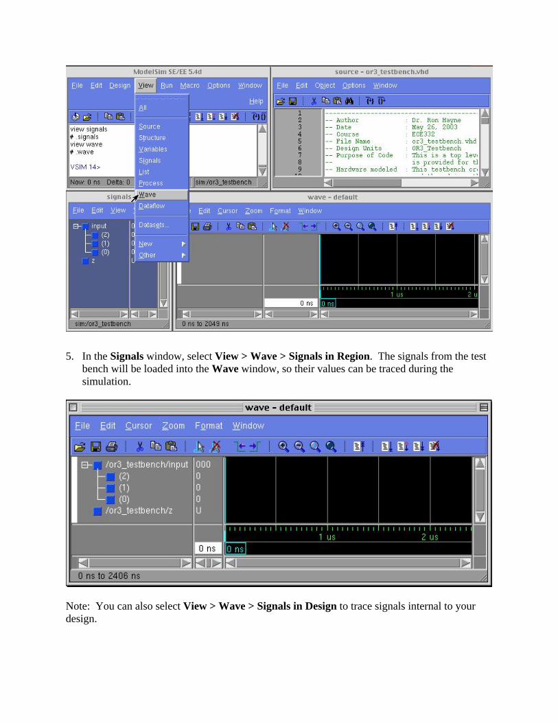
5. In the Signals window, select View > Wave > Signals in Region. The signals from the test bench will be loaded into the Wave window, so their values can be traced during the simulation.
Note: You can also select View > Wave > Signals in Design to trace signals internal to your design.

6. Before starting the simulation, make sure the Run Length is set to an appropriate interval in the main ModelSim window. For this example, the testbench was built with a 100 ns period.
7. Now, you can run the simulation (for 100 ns) using the Run menu in the main ModelSim
window or using the Run button in the toolbar in either the main or wave windows.
The values of the signals will be updated in the Signals window and traced in the Waves window.
Note: The values shown in the Waves window are relative to the cursor, which will be discussed later.

8. Continue running the simulation (using the Run command) until all input combinations have been applied to the test circuit (000 to 111). Alternately, you can use the buttons described below to control starting, stopping, and restarting the simulation. Note: Use the Run –All command with caution.
Main Window Toolbar
Restart Reloads the design and resets the simulation time to zero
Run Run the current simulation for the specified run length
Continue Run Continue the current simulation run until the end of specified run length or until it hits a breakpoint or specified break event
Run –All Run the current simulation forever, or until it hits a breakpoint or specified break event
Break Stop the current simulation run
Step Steps the current simulation to the next VHDL statement
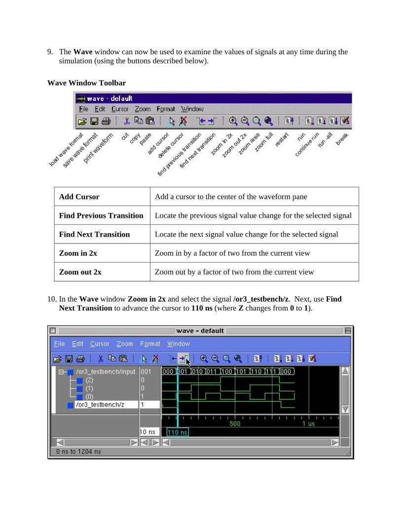
9. The Wave window can now be used to examine the values of signals at any time during the simulation (using the buttons described below).
Wave Window Toolbar
Add Cursor Add a cursor to the center of the waveform pane
Find Previous Transition Locate the previous signal value change for the selected signal
Find Next Transition Locate the next signal value change for the selected signal
Zoom in 2x Zoom in by a factor of two from the current view
Zoom out 2x Zoom out by a factor of two from the current view
10. In the Wave window Zoom in 2x and select the signal /or3_testbench/z. Next, use Find Next Transition to advance the cursor to 110 ns (where Z changes from 0 to 1).

You can see from the signal values shown that the simulation is correctly modeling the behavior described in the VHDL source code for or3.vhd. Specifically, the signal assignment statement below indicates that the signal Z should change to 1, 10 ns after C changes to 1 at 100 ns.
Z <= A or B or C after 10 ns;
11. Lastly, you can print the waveforms from the simulation. From the menu in the Wave
window, select File > Print Postscript (or use the Print button on the toolbar).
Choose “Print command” and enter lp. Use the “Signal Selection” and “Time Range” radio buttons to control the waveforms to be printed.
To obtain a printout of your VHDL source code from your project directory, at the Unix prompt type:
enscript –Ppfp or3.vhd
These commands will send your printouts to a pay-for-print printer.
MGC Software Documentation Further documentation on the MGC software is available on-line. From the main ModelSim window select Help > SE/EE Documentation > SE/EE Bookcase for access to the following: ModelSim SE/EE Quick Guide Provides quick reference to important commands, variables, and tools ModelSim SE/EE User’s Manual Describes how to configure and use ModelSim including topics such as design libraries, VHDL simulation, the GUI, SDF timing annotation, etc. ModelSim SE/EE Command Reference Describes ModelSim commands and associated options that are used from a command prompt or within macro files. Includes a section on command syntax. ModelSim SE/EE Tutorial Leads you step-by-step through common tasks such as compilation, simulation, debugging, and using the Wave window. The same documentation is also available directly on cpe02 using Adobe Acrobat Reader. To read the documentation, at your unix prompt type
acroread & After the program starts (may take a few minutes), open the file
/opt/mgc/fpgadv40/Modeltech/docs/se_docs.pdf The next time you start the acrobat reader, this file will be in the list of files from which you can select so you won't need to type it in each time.