Embed Size (px)
Citation preview

10 Microsystems inSpacecraft Guidance,Navigation, and Control
Cornelius J. Dennehy and Robert Osiander
CONTENTS
10.1 Introduction................................................................................................ 203
10.2 Miniaturized Modular GN&C Subsystems for Microsatellites ................ 205
10.2.1 JPL Micronavigator...................................................................... 207
10.2.2 GSFC Microsat Attitude and Navigation Electronics ................. 207
10.2.3 NMP ST6 Inertial Stellar Camera ............................................... 208
10.3 MEMS Attitude Measurement Sensors..................................................... 211
10.3.1 MEMS Magnetometers ................................................................ 212
10.3.2 MEMS Sun Sensors ..................................................................... 213
10.3.3 Earth Sensors................................................................................ 213
10.3.4 Star Trackers ................................................................................ 214
10.4 MEMS Inertial Measurement Sensors ...................................................... 214
10.4.1 MEMS Gyroscopes ...................................................................... 216
10.4.2 A MEMS Gyro Application Example: The NASA/JSC
AERCam System ......................................................................... 219
10.4.3 MEMS Accelerometers................................................................ 220
10.5 MEMS Attitude Control Devices.............................................................. 220
10.6 Advanced GN&C Applications for MEMS Technology.......................... 221
10.6.1 MEMS Atom Interferometers for Inertial Sensing ..................... 221
10.6.2 Miniaturized GN&C Sensors and Actuators ............................... 222
10.6.3 MEMS-Based Sensitive Skin for Robotic System Control......... 222
10.6.4 Modular MEMS-Enabled Independent Safe Hold Sensor Unit.. 223
10.6.5 Precision Telescope Pointing....................................................... 223
10.7 Conclusion ................................................................................................. 224
References............................................................................................................. 226
10.1 INTRODUCTION
Since the launch of Sputnik (October 4, 1957) significant resources have been
invested in the design and development of guidance, navigation, and control
(GN&C) systems for aerospace vehicles and platforms. As a result, the extraordinary
Osiander / MEMS and microstructures in Aerospace applications DK3181_c010 Final Proof page 203 1.9.2005 12:13pm
203
© 2006 by Taylor & Francis Group, LLC
progress in these critically important systems has been used to measure, guide,
stabilize, and control the trajectory, attitude, and appendages (i.e., steerable antennas,
solar arrays, robotic arms, and pointable sensors) of Earth-orbiting satellites, inter-
planetary spacecraft and probes, space-based robots, planetary rovers, and related
platforms.
A spacecraft’s GN&C system is critical to executing the typical space mission
operational functions such as orbital insertion, Sun acquisition, Earth acquisition,
science target acquisition, pointing and tracking, orbital or trajectory Delta-V
propulsive maneuvers, as well as the articulation of multiple platform appendages.
No matter what the specific mission applications are, all spacecraft GN&C systems
can be deconstructed into the three basic generic functional elements of an auto-
matic feedback control system:
. Sensors
. Processors
. Actuators
Typically, in conventional spacecraft architectures being implemented today, various
individual attitude sensor units (such as star trackers, Sun sensors, Earth sensors,
horizon crossing sensors, magnetometers, rate gyros, accelerometers, etc.) are phys-
ically mounted at discrete locations on the spacecraft structure and electrically
harnessed to the vehicle’s command and data handling system (C&DH). The attitude
measurement data generated by each individual sensor are sampled, at rates ranging
from 1 to 100 Hz typically, by the spacecraft’s on-board digital flight processor in
which attitude determination algorithms compute an updated vehicle state vector.
Control law algorithms, also resident on this on-board processor, will compute the
necessary attitude control torques (and/or forces) required to achieve the desired
attitude, orbit, or trajectory. Command signal outputs from the processor are then
directed to the appropriate attitude control actuators to generate the commanded
torques or forces on the vehicle. This attitude control is cyclically repeated at rates
ranging from 1 to 10 Hz, or possibly faster if the time constants of the fundamental
dynamics of the vehicle to be controlled are very short and high bandwidth control is
required for stabilization.
In the almost 50 years since Sputnik, the global GN&C engineering community
has established and flight-proven multiple methods for determining and controlling
the orientation of spacecraft.1–3 A GN&C engineer’s choice between such basic
control techniques as gravity gradient stabilization, spin stabilization, and full
three-axis stabilization will depend primarily on the mission-unique drivers of orbit
(or trajectory), payload pointing stability and accuracy requirements, spacecraft
attitude and orbital maneuvering requirements and mission life.4 Multiple opportun-
ities exist to infuse microelectromechanical systems (MEMS) technology in many of
these attitude control and stabilization techniques, particularly in the areas of ad-
vanced attitude control system sensors and actuators. Advanced MEMS-based pro-
cessors for GN&C applications are also a possibility, but that specific area of MEMS
R&D will not be discussed in this chapter.
Osiander / MEMS and microstructures in Aerospace applications DK3181_c010 Final Proof page 204 1.9.2005 12:13pm
204 MEMS and Microstructures in Aerospace Applications
© 2006 by Taylor & Francis Group, LLC

While GN&C engineering and technology development efforts are primarily
directed towards both controlling launch vehicle (i.e., booster) dynamics during
ascent and controlling space platform dynamics in the microgravity environment of
free space, they also entail the navigational aspects of maintaining precise timing (and
the associated time transfer and time synchronization functions). MEMS technology
can certainly be applied to the development of miniaturized spacecraft clocks and
oscillators for navigational functions. Table 10.1 defines the typical set of sensing and
control devices typically used to perform spacecraft GN&C functions.
10.2 MINIATURIZED MODULAR GN&C SUBSYSTEMSFOR MICROSATELLITES
Several future science and exploration mission architectures share common
interests and technological requirements for microsatellites. Some envision
economically mass-produced microsatellites as a means to enable new robust,
flexible, and responsive space architectures for Earth (or planetary) observation
and coordinated space communications and navigation functions. Others foresee
clusters of microsats as affordable and reconfigurable platforms for performing new
types of in situ or remote sensing science measurements or observations.
Consequently, many industrial and federal R&D organizations are spearhead-
ing the development of the breakthrough subsystem and component technologies
needed to implement next generation microsatellites. Using data from various flight
projects and cost models, some researchers have investigated the relative costs of
small satellite subsystems as a way to refine the identification of technologies,
which are key to reducing overall spacecraft cost. One such analysis, performed by
NASA’s New Millennium Program (NMP), determined that the largest cost frac-
tions were associated with both the electrical power subsystem, 34% of total cost,
and the GN&C subsystem, 27% of total cost, with the other small satellite subsys-
tems costs being significantly less.5 A general observation can also be made that,
excluding the payload, the GN&C and the C&DH, in the range of 25 to 30% of total
TABLE 10.1Typical Spacecraft GN&C Attitude Sensing and Control Devices
Attitude Sensing Devices Attitude Control Actuation Devices
Sun sensors Thrusters
Earth sensors Momentum wheels
Horizon sensors Reaction wheels
Magnetometers Control moment gyros
Gyroscopes Magnetic torquers
Accelerometers Antenna pointing gimbals
Fine guidance sensors Solar array drives
Osiander / MEMS and microstructures in Aerospace applications DK3181_c010 Final Proof page 205 1.9.2005 12:13pm
Microsystems in Spacecraft Guidance, Navigation, and Control 205
© 2006 by Taylor & Francis Group, LLC

power, are the largest relative power consuming subsystems on small satellites. The
insight gained from these types of studies is that technologies which reduce both
power and mass of the GN&C subsystem will perhaps have the greatest propor-
tional potential to lower small spacecraft costs. Applying higher risk MEMS
technologies to the relatively costly and power consuming GN&C subsystems of
microsatellites, and other small-scale space platforms, is a technology thrust that
has potential for high payoff.
Furthermore, beyond developing technologies that simply reduce mass and
power, the community must also pursue in tandem the creation of architectures that
are modular and based upon commonly applied standards. When contemplating the
design of microsatellites to perform future science and exploration missions, many
space mission architects, space system engineers, and subsystem engineers all share a
common vision in which modular, adaptive and reconfigurable system technologies
enable highly integrated space platform architectures.6 In the GN&C arena the design
of modular multifunction units is being investigated and researched, by both industry
and the government. Such units would effectively coalesce multiple GN&C sensing
and processing functions, and in some instances communications functions, into one
single highly integrated, compact, low-power, and low-cost device. Clearly MEMS
technology, along with other supporting avionics systems technologies, can be
exploited to enable this type of miniature GN&C hardware.
Such a unit would simultaneously provide autonomous real time on-board
attitude determination solutions and navigation solutions. This ‘‘GN&C in a box’’
device would operate as a single self-contained multifunction unit combining the
functions now typically performed by a number of hardware units on a spacecraft
platform. This approach, enabled by MEMS technology and advanced electronics
packaging methods, will significantly reduce the number of electrical, computer
data, and mechanical interfaces for the GN&C system, relative to current engineer-
ing practice, and should therefore payoff with dramatic reductions in costly and
time-consuming prelaunch integration and test activities. However, recognizing
the need to satisfy a variety of future mission requirements, design provisions
could be included to permit the unit to interface with externally mounted sensors
and actuators, as needed, to perform all necessary GN&C functions.
The desired result is a highly versatile unit that could be configured in multiple
ways to suit a realm of science and exploration mission-specific GN&C require-
ments. Three specific examples of modular multifunction GN&C technology de-
velopments are described in this section: the JPL MicroNavigator unit, the GSFC
Microsat Attitude and Navigation Electronics (MANE), and NASA’s NMP Space
Technology 6 (ST6) Inertial Stellar Camera (ISC) under development at Draper
Laboratory. The common design philosophy in all three cases is to merge the
GN&C sensing and data processing elements into a single unit by leveraging
advanced MEMS miniaturization and electronics packaging technologies. The
underlying shared goal is then to be in a position to mass produce these modular
GN&C units so that the overall cost of a next generation microsat is more afford-
able, relative to current production techniques. The evolution and eventual infusion
of these innovative miniaturized modular GN&C systems will rely heavily upon
Osiander / MEMS and microstructures in Aerospace applications DK3181_c010 Final Proof page 206 1.9.2005 12:13pm
206 MEMS and Microstructures in Aerospace Applications
© 2006 by Taylor & Francis Group, LLC

continued MEMS inertial sensor (gyroscopes and accelerometers) technology mat-
uration, not so much to further reduce device mass and power, but to significantly
improve accuracy and overall sensor performance.
10.2.1 JPL MICRONAVIGATOR
Miniature high-performance, low-mass, low-power space avionics are among the
high-priority technology requirements for planetary exploration missions. The
spacecraft fuel and mass requirements enabling orbit insertion is the driving re-
quirement. The MicroNavigator is an integrated hardware and software system
designed to satisfy the need of a miniaturized GN&C unit for navigation, attitude
determination, vehicle attitude control, pointing, and precision landing.7
The MicroNavigator concept depends on MEMS technology. In particular,
MEMS-based gyroscope and accelerometer inertial sensors were targeted for the
MicroNavigator avionics package. Miniature celestial sensors such as active pixel
sensor (APS) and miniaturized GPS sensors, were also identified as key technology
elements of the MicroNavigator.
The MicroNavigator has a dedicated embedded processor to perform GN&C
specific computations. A state estimator hosted on this internal processor optimally
filters data from the MEMS inertial sensors (as well as other sensors). A high-
resolution (0.18 in attitude knowledge and 10–50 m position determination accur-
acy) vehicle state vector is output by the MicroNavigator potentially at cycle rates
of less than 1 sec. Two obvious benefits are derived here at the system-level by
virtue of using the MicroNavigator: (1) the spacecraft on-board flight computer (if
there is even one) is not encumbered with the task of performing the computation-
ally intense GN&C algorithm processing and (2) the GN&C algorithms embedded
within the MicroNavigator are generally applicable to a wide variety of mission
applications so that new flight software design and development is not required,
thus, significantly lowering the cost of implementing GN&C functionality on a
given spacecraft.
Resource requirement goals for the MicroNavigator are ambitious: a mass
target of less than 0.5 kg, a volume of about 8 cubic inches, and a power require-
ment of less than 5 W.
10.2.2 GSFC MICROSAT ATTITUDE AND NAVIGATION ELECTRONICS
In a manner very similar to the MicroNavigator the MANE represents a revolu-
tionary leap in the design and implementation of spacecraft GN&C subsystems.
MANE is a single, highly integrated, space-efficient, low-power, affordable hard-
ware or software design concept (targeted, but not limited to, microsat applica-
tions), which autonomously provides attitude determination and navigation
solutions. The MANE would obviate the need for a separate GPS receiver unit, a
separate GN&C processor, a separate inertial reference unit (IRU) and a separate set
of attitude-control interface electronics. An embedded (card-mounted) three-axis
MEMS gyroscope sub-assembly would replace the conventional IRU which is
relatively large, heavy, and power consuming.
Osiander / MEMS and microstructures in Aerospace applications DK3181_c010 Final Proof page 207 1.9.2005 12:13pm
Microsystems in Spacecraft Guidance, Navigation, and Control 207
© 2006 by Taylor & Francis Group, LLC

The MANE design concept was an outgrowth of earlier work on a multifunc-
tional GN&C System (MFGS) performed at GSFC.8 The mass and power resource
requirement goals for the MFGS were 2.5 kg and 12 W, respectively. While the
MFGS design represented substantial improvement in overall GN&C subsystem
resource requirements, the MANE concept was developed to drive the MFGS
design to the next level of miniaturization with an ultimate, long-term, high-risk
goal of developing an ultra-miniature design that captures the MFGS performance
in a volume of several cubic inches employing MEMS microsystems, advanced
space avionics electronics packaging or assembly technologies together with the
ultra low power (ULP) electronics technology being pioneered by the University
of Idaho and GSFC.9 The very space-efficient chip-on-board (COB) technology,
pioneered by the Johns Hopkins University Applied Physics Laboratory (JHU/
APL), was identified as a viable initial technique to achieve the miniaturization
goal for MANE. COB achieves up to 10� higher circuit density by attaching bare
die directly to the underlying board.
The MANE performance capabilities will largely depend on the individual
mission requirements and the available set of navigation and attitude sensor data.
The MANE design utilized a single reusable GN&C software system architecture
for which the performance capabilities can be tailored for individual missions
obviating the need for expensive new flight software design and development.
Attitude determination performance goals for the MANE ranged between 0.1 and
0.38 without the external star sensor data and 1–2 arc-seconds with the external
star sensor data. The MANE design goals were to achieve power consumption of
less than 3 W, a unit mass of less than 1 kg in a total volume of less than 10 cubic
inches.
10.2.3 NMP ST6 INERTIAL STELLAR CAMERA
NASA’s NMP is sponsoring the development of the Inertial Stellar Compass (ISC)
space avionics technology that combines solid-state MEMS inertial sensors (gyro-
scopes) with a wide field-of-view APS star camera in a compact, multifunctional
package.10 This technology development and maturation activity is being per-
formed by the Charles Stark Draper Laboratory (CSDL), for a Space Technology
6 (ST6) flight-validation experiment now scheduled to fly in 2005. NMP missions
such as ST6 ISC are intended to validate advanced technologies that have not yet
flown in space in order to reduce the risk of their infusion in future NASA missions.
The ISC technology is an outgrowth of earlier CSDL research focused in the areas
of MEMS inertial device development,11 MEMS-based GN&C sensors and actu-
ators,12 and low-power MEMS-based space avionic systems.13
The ISC, shown in Figure 10.1, is a miniature, low-power, stellar
inertial attitude determination system that provides an accuracy of better than 0.18(1-Sigma) in three axes while consuming only 3.5 W and packaged in a 2.5 kg
housing.14
The ISC MEMS gyro assembly, as shown in Figure 10.2, incorporates CSDL’s
tuning fork gyro (TFG) sensors and mixed signal application specific integrated
Osiander / MEMS and microstructures in Aerospace applications DK3181_c010 Final Proof page 208 1.9.2005 12:13pm
208 MEMS and Microstructures in Aerospace Applications
© 2006 by Taylor & Francis Group, LLC

circuit (ASIC) electronics designs. Inertial systems fabricated from similar
MEMS gyro components have been used in PGM, autonomous vehicles, and
other space-related mission applications. The silicon MEMS gyros sense angular
rate by detecting the Coriolis effect on a sense mass. A sense mass is driven into
oscillation by electrostatic motors. The mass oscillates in one axis and as the body is
Alignment reference cube
CGA housing
Baffle
Lens assembly
DC-DCconverter
Camera PWA
DPA PSE PWA
Controller and PSE PWA
DPA housing
Processor PWA
Lens and camera support assembly
DC-DC converter
Gyro PWA
FIGURE 10.1 The NMP ST6 ISC. (Source: NASA JPL/CALTECH.)
FIGURE 10.2 NMP ST6 ISC MEMS three-axis gyro assembly. (Source: Charles Stark
Draper Laboratory.)
Osiander / MEMS and microstructures in Aerospace applications DK3181_c010 Final Proof page 209 1.9.2005 12:13pm
Microsystems in Spacecraft Guidance, Navigation, and Control 209
© 2006 by Taylor & Francis Group, LLC

rotated, Coriolis forces cause the sense mass to oscillate out of plane. This change is
measured by capacitive plates and is proportional to the rotational rate of the body.
The MEMS three-axis gyro sub-assembly used in the SC is depicted in
Figure 10.2. The specific MEMS inertial sensing instrument used in the ISC is
the TFG14-R3, 20-mm thick gyro fabricated in a silicon-on-insulator process that
incorporates novel features for high performance. Under typical operating condi-
tions, the MEMS gyroscopes drive the ISC output attitude. The MEMS gyros
sensed inertial rates are sampled, at the high sample frequency of 100 Hz, by the
embedded flight processor. The raw gyro data are then processed using a Kalman
filter algorithm to produce the estimated reference attitude quaternion, which is
communicated to the host spacecraft in real time, at a frequency of 5 Hz. The APS
star camera is used periodically (every few minutes) to obtain a camera quaternion,
whose main purpose is to compensate the inherent drift of the gyros. A simple
system data flow is shown in Figure 10.3.
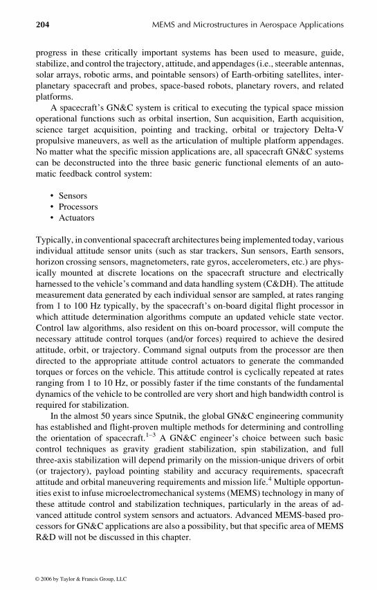
A typical profile of attitude error, computed by simulation, is shown in
Figure 10.4. The 1-sigma error bounds are shown in bold, while the actual attitude
error from one simulated run is shown as a thin line. Since the error bounds are
1-sigma, the error can be expected to go outside of the bound for 32% of the time.
Every 5 min, the gyros are compensated with a fresh star camera quaternion, as
evidenced by the sudden narrowing of the error bounds. Used together as a tightly
integrated sensor suite, the MEMS gyros and star camera enhance each other’s
Gyro data
Attitude
Time stampedquaternion fromcamera processing
Low frequency controllersRequest at 50 Hz
Camera data
∆θ PulsesTemp
High frequency
Gyro acquisition100 Hz
Gyrocompensation
ECI quaterniondetermination
Kalmanfilter
(Square root typewith 27 states)
Starimages
Compensation
Img. processingand attitude
determination
FIGURE 10.3 NMP ST6 ISC attitude determination system data flow. (Source: NASA
CALTECH/JPL.)
Osiander / MEMS and microstructures in Aerospace applications DK3181_c010 Final Proof page 210 1.9.2005 12:13pm
210 MEMS and Microstructures in Aerospace Applications
© 2006 by Taylor & Francis Group, LLC
capabilities, resulting in a more robust attitude determination system than could be
achieved by integrating separate star tracker and gyro units.
The ISC technology, enabled by embedded MEMS gyroscopes, is a precursor
of things to come in the spacecraft avionics arena as much more highly integrated,
lower power, MFGS are developed in the future. There are a wide range of science
and exploration mission applications that would benefit from the infusion of the
compact, low-power ISC technology. Some envisioned applications include using the
ISC as a ‘‘single sensor’’ solution for attitude determination on medium performance
spacecraft, as a ‘‘bolt on’’ independent safehold sensor for any spacecraft, or as
an acquisition sensor for rendezvous applications. It has been estimated that
approximately 1.5 kg of mass and 26 W of power can be saved by employing a
single MEMS-based attitude sensor such as the ISC to replace the separate and
distinct star tracker and IRUs typically used on spacecraft.14 So in this case, MEMS
is an enhancing technology that serves to free up precious spacecraft resources.
For example, the mass savings afforded by using the MEMS-based ISC could
be allocated for additional propellant or, likewise, the power savings could poten-
tially be directly applied to the mission payload. Also worth noting is the fact
that the significantly low ISC power consumption will have a positive secondary
benefit of reducing the size and cost of the host spacecraft electrical power subsystem.
These are some of the advantages afforded by using MEMS technology for GN&C
applications.
10.3 MEMS ATTITUDE MEASUREMENT SENSORS
An attitude measurement is the measurement of any quantity sensitive to the
attitude of the spacecraft, for example, the magnetic field vector, the direction of
the Sun, a star, or some other body, the measurement of an angle such as the solar
aspect or the limb of a planetary body, or the measurement of integrated angular rates.
The latter is very different since it does not provide absolute attitude information. By
the resolution they provide, the attitude sensors can be divided into two groups, coarse
sensors such as magnetometers, sun sensors, and Earth horizon sensors, and fine
sensors such as fine sun sensors and star sensors. Attitude determination using the
global positioning systems (GPS) or similar systems will not be discussed here.
0.1
0.05
0
FoA
Rol
l (de
g)
0 10
Attitude Errors and Kalman Covariance
20−0.1
−0.05
FIGURE 10.4 Typical ISC single-axis attitude error profile.
Osiander / MEMS and microstructures in Aerospace applications DK3181_c010 Final Proof page 211 1.9.2005 12:13pm
Microsystems in Spacecraft Guidance, Navigation, and Control 211
© 2006 by Taylor & Francis Group, LLC

The MEMS technologies used for these systems are similar to those discussed in
Chapter 8.
In general, there are several design considerations that must be considered in
the design of spacecraft attitude sensors. Chief among these are the specific nature
of the control system application. The constraints associated with predicted en-
vironmental conditions such as the prelaunch handling, launch loads (mechanical
vibration or shock as well as acoustic exposure), pressure venting profiles, on-orbit
operating temperatures, particle contamination, EMI or EMC effects, and radiation
exposure (both the total dose and heavy ions) must be well understood and docu-
mented prior to the detailed design phase of the sensor.
Other system level, but no less important, considerations come into play with
spacecraft attitude sensors such as the specific placement and orientation of the
device on the spacecraft or platform structure to be controlled. Inadequate attention
to these details, especially on very lightweight highly flexible structures, can lead to
destabilizing (and, in extreme cases, possibly destructive) controls–structures inter-
action (CSI) problems for the GN&C designer.
The imminent introduction of the MEMS-based GN&C sensor technology into
the spacecraft designer’s inventory will herald a breakthrough in how the function
of medium-to-high accuracy attitude determination will be implemented in future
space missions.
10.3.1 MEMS MAGNETOMETERS
MEMS magnetometers have already been discussed in Chapter 7, Microtechnologies
for Science Instrumentation Applications. A magnetometer measures the three com-
ponents of the magnetic field and provides a measurement of the attitude relative to
inertial coordinates. Since only the direction of the magnetic field is sensitive to the
attitude, another vector measurement such as a sun sensor is required for attitude
determination. For magnetometers, the largest component of the random noise for
attitude determination arises not from the sensor itself, but from the magnetic field
model, which, for LEO orbits, can cause an error of 0.58 at the equator, and up to 38near the magnetic poles. Therefore, the sensitivity requirements for magnetometers
as an attitude sensor are relatively weak and provide an opportunity for insertion of
MEMS devices. The performance requirements for attitude determination magnet-
ometers are a range of about +60 mT, with a sensitivity of +10 nT.
A number of miniature magnetometer developments have occurred in recent
years. For the SUNSAT-1 satellite, the magnetic observatory at Hermanus manu-
factured a miniature fluxgate magnetometer with this performance at a size of about
130 mm � 90 mm � 36 mm and a weight of 295 g.
The University of California, Los Angeles, has developed a miniature fluxgate
magnetometer for NASA’s NMP ST5 small satellite mission. The magnetometer
mass and power is kept low with a dual core series drive circuit. The magnetometer
has two commendable ranges, 64,000 and 1000 nT. The dynamic range is changed
from 64,000 to 1000 nT by altering the closed loop response from 64,000 to 5000
nT, and then amplifying the signal to get to a 1000 nT range. This method keeps the
Osiander / MEMS and microstructures in Aerospace applications DK3181_c010 Final Proof page 212 1.9.2005 12:13pm
212 MEMS and Microstructures in Aerospace Applications
© 2006 by Taylor & Francis Group, LLC

noise low in both ranges. One gain change command line switches both elements.
Total mass of the ST5 magnetometer is approximately 600 g and it consumes
approximately 0.55 W of power.
The magnetometers are calibrated in-orbit to correct the prelaunch gain and
offset parameters. Misalignment of the orthogonal pickup coils and sensor mount-
ing errors are also determined once in orbit. Examples of possible MEMS magnet-
ometers are based on Lorentz force using resonating bars and membranes.15–17
10.3.2 MEMS SUN SENSORS
A sun sensor determines the vector direction of the Sun, and can be either a coarse
or even a very fine attitude sensor. Many sun sensors rely, much like a sun dial, on
the shadowing effects of some masks. When reducing the size of the masks to
MEMS dimensions, problems arise due to diffraction as well as the reduced angular
deflection at these small dimensions. Two categories of conventional sun sensors
exist — digital and analog types. The digital sun sensors illuminate a geometric
pattern on the detector plane. The presence or absence of light in these well-defined
areas defines a digital signal that can be translated into the sun angle. An analog sun
sensor outputs analog currents, from which the sun angles can be derived. This
simple approach of the digital sun sensor, where the mask design creates a digital
read out of the sun position, will no longer work. A typical approach to reduce the
dimensions of a sun sensor is to use an imager and determine the centroid of a
shadow pattern generated by a mask. The mask can be produced using microma-
chining technology, which, if it can be inserted into the same process steps, could
increase the accuracy and reduce handling when producing such a sensor. One
example of such a sun sensor has been produced at JPL.18–20 This micro sun sensor
is essentially a pinhole camera with multiple holes, and is comprised of a silicon
wafer mask with several hundred small apertures placed on top of a charge coupled
device (CCD) focal plane array at a distance of 750 mm. An image of the apertures
is formed on the focal plane when the Sun illuminates this setup. Sun angles can be
derived by analyzing the image. The experimental data presented indicate that
this sun sensor can achieve accuracies in the order of a few arcminutes or better.
It is projected that this type of sun sensor will be the size of three dimes stacked
on top of each other. It will have a mass of less than 30 g and consume less than
20 mW.
10.3.3 EARTH SENSORS
Earth horizon sensors use the Earth’s horizon to determine spacecraft attitude. In
LEO, they concentrate on merely telling which direction is down; in geosynchron-
ous earth orbit (GEO), they focus on the actual horizon and yield more accurate
attitude measurements. Since they are typically based on an IR detector, bolo-
meters, and uncooled imagers based on MEMS fabrication technology, as described
in Chapter 7 under spacecraft instrumentation, can be effectively used. An example
of such a device is the Micro Infrared Earth Sensor (MIRES) developed at LAAS-
CNRS in France.21–23 It uses an uncooled 320 � 240 infrared sensor array with a
Osiander / MEMS and microstructures in Aerospace applications DK3181_c010 Final Proof page 213 1.9.2005 12:13pm
Microsystems in Spacecraft Guidance, Navigation, and Control 213
© 2006 by Taylor & Francis Group, LLC

noise-equivalent temperature (NET) of 100 mK and smart processing to measure
the position of the horizon.
10.3.4 STAR TRACKERS
Star sensors are very similar to sun sensors. Star cameras are star sensors that sense
several stars at once. Recent developments in CCDs have reduced power require-
ments for these considerably, making them more practical. They are very accurate.
A system involving MEMS mirrors has been developed with the Air Force Research
Laboratory (AFRL) together with NASA Langley Research Center in form of the
intelligent star tracker (IntelliStar).24 It uses several novel technologies including
silicon carbide housing, MEMS adaptive optics, smart active pixels, and algebraic
coding theory. In addition to being lightweight, it also offers advantages of speed,
size, power consumption, and radiation tolerance. The MEMS-adaptive optics,
utilizing MEMS mirrors developed at AFRL, and fabricated with Sandia’s SUM-
MiT V process (Chapter 3), compensate for geometrical aberrations and effects, and
allow the imager to match star patterns easier and faster. Research on miniature
MEMS star sensors has also been performed at JPL.25,26
10.4 MEMS INERTIAL MEASUREMENT SENSORS
Gyroscopes (also commonly referred to as ‘‘gyros’’) and accelerometers are
the building blocks from which most spacecraft GN&C systems are built. They
are called inertial sensors since their operation takes advantage of an object’s
resistance to change momentum, or simply put, its inertia. Gyros have been
used in space mission applications for many decades and there is a rich body of
technical literature concerning the theory and practical operation of gyro instru-
mentation.27
The technology of inertial sensors, first developed in the 1920s, has continually
evolved in response to the demands of the users. In the beginning the trend was
to maintain the same basic designs while pushing the technology for sensor-level
components (e.g., electronics, bearings, suspensions, motors, etc.) to achieve im-
provements in sensor performance and operational reliability. Significant increases
in inertial system accuracy and reliability accomplished over this time period
directly led to the successes in autonomous submarine navigation, the Apollo
missions, and the ubiquitous infusion of inertial navigation on commercial aircraft.
Since the 1970s or thereabout, performance plateaued and the emphasis shifted
from refining the technology to achieving equivalent high performance at reduced
cost. Over the past 20 years or so, MEMS technology breakthroughs have been
exploited to create innovative microsystem solution for applications not previously
considered feasible for inertial sensing. These emerging MEMS-based inertial
sensor technologies offer little performance improvement, but provide benefits of
low production and life-cycle costs, miniature size, low mass and power consump-
tion, and are enabling for microsatellites.28
Osiander / MEMS and microstructures in Aerospace applications DK3181_c010 Final Proof page 214 1.9.2005 12:13pm
214 MEMS and Microstructures in Aerospace Applications
© 2006 by Taylor & Francis Group, LLC

In certain highly maneuverable spacecraft, or propulsive upper stage applica-
tions, a three-axis gyro sensor complement for rotational sensing is combined with
a three-axis set of accelerometers for translational sensing to implement a full six
degree-of-freedom (6-DOF) inertial measurement unit (IMU). In navigation and
flight-control systems, an IMU is used to measure angular rates and translational
accelerations about three orthogonal axes of the spacecraft: the roll, pitch, and yaw.
Depending on the mission applications, IMU’s may have 4-for-3 gyro and acceler-
ometer redundancy. In other attitude control systems a three-axis gyro sensor
configuration alone, forming an inertial reference unit (IRU), is employed on
spacecraft.
The technologies commonly used in today’s IRUs include high-performance
mechanical (spinning mass) gyros such as those used on the Hubble Space Tele-
scope, Ring Laser Gyros (RLGs), Fiber Optic Gyros (FOGs) and HRGs. Three-axis
IRU packages based upon these gyro technologies are the mainstay of spacecraft
GN&C systems. One such IRU that has been used on a wide range of LEO, GEO
and deep-space mission applications has a mass of approximately 4.5 kg and
typically requires over 20 W of power to operate. Another representative IRU
used on a large space platform had mass of 5 kg and consumed about 18 W of
power. Consequently, these types of conventional IRU will not be amenable to
microsatellite (and other mission) applications where mass and power are at a
premium.
MEMS inertial sensors are therefore an attractive technology option to pursue
for future microsatellite missions, and other science or exploration applications
such as probes, rovers, robots and the like, where available mass and power
resources are severely constrained. Microsatellite designers and developers can
leverage the considerable R&D funding that has already been invested by the
Department of Defense (DoD) in the development of MEMS inertial sensor tech-
nologies. The primary mission applications of these investments have been preci-
sion-guided munitions (PGMs) and unmanned robotic vehicles. In both these
military applications, the MEMS-based IMUs have supplanted competing techno-
logies (e.g., RLGs or FOGs) by virtue of their miniature size, cost, and mechanical
robustness. In the case of the extended range guided munition (ERGM) the MEMS-
based IMU is coupled with a GPS receiver to create a highly compact, very
accurate, and jamming-resistant GPS/INS navigation system for a 5-in. artillery
shell.29
As mentioned above, the overwhelming majority of the technology investment
to date has been focused on consumer class and tactical class MEMS gyros, not
MEMS gyros intended for space applications. This legacy of nonspace MEMS gyro
R&D work has been extensively reviewed and reported on in the literature and will
not be discussed in detail here.30,31 While there has been a considerable R&D
investment in MEMS gyros for military and commercial applications since the
1980s, it is only recently that the development of navigation class MEMS
gyros (with bias stability performance in the range of 0.002 to 0.018/h)
specifically designed for space mission applications has grown at a number of
R&D organizations.
Osiander / MEMS and microstructures in Aerospace applications DK3181_c010 Final Proof page 215 1.9.2005 12:13pm
Microsystems in Spacecraft Guidance, Navigation, and Control 215
© 2006 by Taylor & Francis Group, LLC
Several MEMS inertial sensor technology developments specifically targeted
for space mission are underway at multiple organizations. MEMS sensors in the
space environment have also undergone limited testing and evaluation.32 These
developments obviously build upon the solid MEMS technology foundation already
formed within industry for defense and commercial applications. MEMS micro-
systems are currently at a point where their inherent robustness, miniature size, and
low-power and low-mass attributes make them extremely attractive to spacecraft
GN&C designers. Several key issues, however, remain to be resolved before
MEMS inertial sensors will displace the current family of flight-proven gyro and
accelerometer technologies. When one considers the demanding GN&C require-
ments for most space missions it becomes apparent that a MEMS gyro, with
performance and reliability characteristics suitable for guiding the relatively
short-duration flight of a PGM, may not be a realistic alternative. In general,
significant improvements in the standard performance metrics (drift, scale factor,
etc.) of the current generation of MEMS inertial sensors must be accomplished in
tandem with the ability to rigorously demonstrate the reliability specifications for
space flight.
It is encouraging to observe that the majority of industrial inertial system
vendors are either currently offering or actively developing MEMS-based
IMUs.33 Based upon this trend, and if current R&D investment remains stable or
increases, robust and reliable higher performing space qualified MEMS-based
inertial systems will be commonly available as COTS products within the next 5
to 10 years.
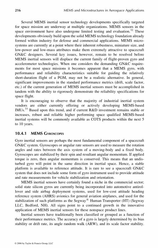
10.4.1 MEMS GYROSCOPES
Gyro inertial sensors are perhaps the most fundamental component of a spacecraft
GN&C system. Gyroscopes or angular rate sensors are used to measure the rotation
angles and rates between the axis system of a moving-body and a fixed body.
Gyroscopes are stabilized by their spin and resultant angular momentum. If applied
torque is zero, then angular momentum is conserved. This means that an undis-
turbed gyro will point in the same direction in inertial space. Hence, a stable
platform is available to reference attitude. It is rare to see a spacecraft GN&C
system that does not include some form of gyro instrument used to provide attitude
and rate measurements for vehicle stabilization and orientation.
MEMS inertial sensors have certainly found a niche in the commercial sector;
solid state silicon gyros are currently being incorporated into automotive antirol-
lover and side airbag deployment systems, used for low-cost attitude heading
reference system (AHRS) avionics for general aviation airplanes, and used for the
stabilization of such platforms as the Segway1 Human Transporter (HT) (Segway
LLC, Bedford, NH). All signs point to a continued growth in the innovative
application of MEMS inertial sensors for these nonspace product lines.
Inertial sensors have traditionally been classified or grouped as a function of
their performance metrics. The accuracy of a gyro is largely determined by its bias
stability or drift rate, its angle random walk (ARW), and its scale factor stability.
Osiander / MEMS and microstructures in Aerospace applications DK3181_c010 Final Proof page 216 1.9.2005 12:13pm
216 MEMS and Microstructures in Aerospace Applications
© 2006 by Taylor & Francis Group, LLC

Other performance parameters such as angular rate sensing range and dynamic
bandwidth also are used to characterize and classify gyros. There are typically four
classes of gyros, in order of decreasing accuracy; precision (or strategic) class,
navigation class, tactical class, and consumer class. The overwhelming majority of
MEMS gyro R&D activities to date have been focused on gyros in either the tactical
performance class having bias stabilities in the range of 1 to 108/h or in the
consumer class where bias stability may be in the range of 100 to 10008/h or even
greater.
With the goal of developing navigation grade MEMS gyroscopes, DARPA has
invested in a number of programs, and has dramatically propelled MEMS inertial
sensor technology for DoD applications. Realizing its importance for space
applications, NASA, and especially JPL, has invested in the MEMS gyroscope
technology for space applications.34,35
JPL has been developing a miniature single-axis vibratory, Coriolis force
MEMS gyro, over the past several years.36 A photograph of the JPL post resonator
gyroscope (PRG) MEMS gyro can be seen in Figure 10.5. It employs a ‘‘cloverleaf’’
planar resonator. In this design the coupling is measured between orthogonal modes
of a four-leaf clover resonator with a proof mass (the post) in the center caused by
the Coriolis force.34 The layout of the device takes the shape of a ‘‘cloverleaf’’ with
two drive electrodes and two sense electrodes located at the quadrants (one elec-
trode per quadrant). A relatively large post is rigidly attached to the center of the
cloverleaf device formed by the four electrodes.
FIGURE 10.5 The JPL vibrating post micromachined MEMS gyro. (Source: NASA
CALTECH/JPL.)
Osiander / MEMS and microstructures in Aerospace applications DK3181_c010 Final Proof page 217 1.9.2005 12:13pm
Microsystems in Spacecraft Guidance, Navigation, and Control 217
© 2006 by Taylor & Francis Group, LLC
Excitation of the microgyro dynamics is achieved by applying a potential to the
two drive electrodes. The drive electrodes and sense electrodes are suspended by
silicon springs above matching electrodes on the base plate. The post adds inertia to
the system which boosts the sensitivity to rotational motion. The electrical potential
between the drive electrodes and their respective base plate electrodes creates an
electrostatic force that, ideally, rocks the cloverleaf assembly about the y-axis. The
amplitude of the rocking motion can be maximized by driving the electrodes at the
natural frequency of this DoF, known as the drive mode. If the device is rotated
about the z-axis, then the rocking about the y-axis is coupled into rocking about the
x-axis via Coriolis acceleration in the x–y frame fixed to the gyro. The rocking
about the x-axis is referred to as the sense mode and the x-axis response is related to
the angular rate of rotation about z. The operating principles of the PRG microgyro,
fabrication details, and preliminary performance results have been extensively
documented.
Other gyroscopes, such as the ones designed by BEI Sensor and Systems
Company, use tuning fork designs, where the result of the Coriolis force is a
vibration mode orthogonal to the standard in plane tuning fork mode.30,37
Also, as previously discussed, the Draper Laboratory MEMS TFG design
has been optimized for infusion in the NASA NMP ST6 ISC flight hardware.
Similar to the JPL PRG, the principle of operation for the Draper Laboratory
MEMS TFG is fundamentally based upon the Coriolis force. The resonant structure
is composed of two proof masses which are each driven electrostatically with
opposite oscillatory phases. Alternating voltages applied to the outer motor drive
electrodes create electrostatic forces between the interlocking tines of the motor
electrode and proof mass, which results in lateral (in the plane of the wafer)
oscillatory motion. The proof masses are driven in a tuning-fork resonance mode.
In response to an angular rate, V, being applied about the input axis, perpendicular
to the velocity vector of the masses, a Coriolis acceleration is produced which
forces the masses to translate in and out of the plane of oscillation. This resultant
antiparallel, out-of-plane motion is measured via the capacitive pick-off, providing
an output signal proportional to the rate input. Closed-loop control is employed to
maintain the proof mass at constant amplitude and the rate sensing is conducted in
an open loop manner.
The successful operation of this device depends on the electronics that controls
the mechanism motion and senses the rate output. Each gyro axis requires an analog
ASIC and a supporting field programmable gate array (FPGA), both on ball grid
arrays. The gyro electronics requires only power and needs no direction from the
microprocessor board except for requests for information. Gyro rate information
is currently sampled at a fixed rate of 600 Hz, and the resultant information is
communicated digitally through a low-voltage differential signaling (LVDS) inter-
face to the microprocessor. The gyro electronics and the packaged gyro sensors are
placed on printed wiring boards and can be assembled by standard pick and place
assembly equipment.
Osiander / MEMS and microstructures in Aerospace applications DK3181_c010 Final Proof page 218 1.9.2005 12:13pm
218 MEMS and Microstructures in Aerospace Applications
© 2006 by Taylor & Francis Group, LLC

10.4.2 A MEMS GYRO APPLICATION EXAMPLE: THE NASA/JSCAERCAM SYSTEM
One very timely application of MEMS gyro is on the miniature autonomous
extravehicular robotic camera (Mini-AERCam) free-flying robotic inspection ve-
hicle being developed by the Engineering Directorate at NASA’s Johnson Space
Flight Center (JSC). The Mini-AERcam system, shown in Figure 10.8, is being
developed to satisfy remote viewing and inspection needs foreseen for future human
space flight missions on the Space Transportation System (STS) Shuttle and the
International Space Station (ISS). The Mini AERCam will provide unique free-
flying video imaging of assembly, maintenance, and servicing tasks that cannot be
obtained from fixed cameras, cameras on robotic manipulators, or cameras carried
by EVA crewmembers. On ISS, for example, Mini-AERCam could be used for
supporting robotic arm operations by supplying orthogonal views to the robot
operator, for supporting crew spacewalk operations by supplying views to the
ground crews monitoring the spacewalk, and for carrying out independent visual
inspections of areas of interest around the ISS.38
Representing a significant technology breakthrough in the field of free-flying
robotic space vehicles, the nanosatellite-class spherical Mini-AERCam free flyer is
7.5 in. in diameter and weighs approximately 10 lb. Advanced miniaturized avionics
and instrumentation technology, together with compact mechanical packaging
techniques, permit the Mini-AERCam to incorporate many additional capabilities
compared to the 35 lb, 14 in. AERCam Sprint free flyer that flew as a remotely piloted
shuttle flight experiment in 1997. Where the Sprint AERCam used quartz rate
sensors, the Mini-AERcam GN&C hardware complement includes higher perform-
ance MEMS gyros for measuring vehicle angular rates. The Mini-AERCam attitude
control system uses angular rate measurements from a three-axis Draper Laboratory
developed MEMS TFG-14 gyros to estimate inertial attitude and attitude rate. The
FIGURE 10.6 The NASA/JSC mini-AERCam free-flying robotic inspection vehicle.
(Source: NASA.)
Osiander / MEMS and microstructures in Aerospace applications DK3181_c010 Final Proof page 219 1.9.2005 12:13pm
Microsystems in Spacecraft Guidance, Navigation, and Control 219
© 2006 by Taylor & Francis Group, LLC

MEMS gyro package outputs digital data at a rate of 300 Hz, which is averaged down
to a 25 Hz rate. The body axis roll, pitch, and yaw attitude rate measurements
are converted to quaternions and then integrated to maintain an estimate of
inertial attitude. The MEMS gyros are used to support the autonomous attitude
determination and control functions in automatic stationkeeping, point-to-point
maneuvering, and automated docking operational modes. In those modes where
relative attitude estimates of the Mini-AERCam (with respect to the Shuttle, the
ISS, etc.) the MEMS gyro-based inertial attitude reference is transformed to other
reference frames.
10.4.3 MEMS ACCELEROMETERS
The development of MEMS accelerometers has been driven by the demand of
the automobile industry for an inexpensive accelerometer as an airbag sensor.
Analog devices has very successfully integrated CMOS electronics with a MEMS
accelerometer in their iMEMS process design to make such devices available inex-
pensively.39,40 The noise levels on the most recent models from analog devices
airbag crash sensors ADI are in the order of 100 micro/Hz1/2 on a 2.5 mm2 area.41
The latest devices are built using silicon on insulator (SOI) MEMS technology, which
allows for larger proof masses than surface micromachining in a single-crystal
silicon layer.
In future designs, given the miniscule additional power, mass, and volume re-
quirements imposed by a three-axis MEMS accelerometer package, it would be
very reasonable to simply integrate the accelerometers, electrically and mechanically,
with a three-axis gyros to create a full 6-DOF spacecraft IMU. Accelerometers
could be used for navigating and perhaps also for such functions as thruster calibration,
drag force measurement, monitoring launch environments g-loads, or, due to the
small size, they could be placed anywhere on the spacecraft such as along a boom
to measure vibrations. The Aerospace Corporation has developed a very compact
triaxial accelerometer with the capability of measuring the vibration direction at
specific points.42 Similar systems have also been developed at the CSDL, with
Brownian-limited noise floors at 1.0 g/pHz; orders of magnitude more sensitive than
state-of-the-art surface micromachined devices such as the industry standard
ADXL05.43
10.5 MEMS ATTITUDE CONTROL DEVICES
There are two fundamental ways to control spacecraft attitude, either by applying
torques on the external via propulsion, or by changing the angular momentum with
reaction wheels. Of course, any action, the spring-supported launch of a probe, or
the start of a motor, will cause a change in the attitude if not compensated. Chapter
11 deals with micropropulsion, and therefore these systems will not be discussed
here. It is important to know, however, that the specific impulse of some of the
micropropulsion systems is enough, and especially, can be controlled to a fine
enough thrust, to provide means of attitude control for even larger spacecraft.
Osiander / MEMS and microstructures in Aerospace applications DK3181_c010 Final Proof page 220 1.9.2005 12:13pm
220 MEMS and Microstructures in Aerospace Applications
© 2006 by Taylor & Francis Group, LLC

Reaction wheels use electric motors to torque against high-inertia rotors or
‘‘wheels.’’ When the motor exerts a torque on the wheel, an equal and opposite
reaction torque is applied to the spacecraft. Reaction wheels are typically operated
in a bi-directional manner to provide control torque about a single spacecraft
axis. The inherently small inertia of a typical MEMS device will make them less
efficient as a reaction wheel type actuator, and can only be compensated by
extremely high speeds, which challenges the reliability requirements for such
devices.
Microwheels for attitude control and energy storage have been suggested
and designed by Honeywell.44 They project a performance of a momentum
density of 9 N m sec/kg and an energy storage of 14 W h/kg for a wheel of 100
mm diameter micromachined in a stack of silicon wafers. The advantages of
microwheels increase further when the device is incorporated in the satellite’s
structure.
Likewise, Draper Laboratory has studied both the adaptation of a wafer spin-
ning mass gyro and an innovative wafer-sized momentum wheel design concept
(using hemispherical gas bearings) as attitude control actuators for a 1 kg nanosa-
tellite application.12
A similar system, based on high-temperature superconductor (HTS) bearings,
was suggested by E. Lee. It has an energy storage capacity of about 45 W h/kg, and
could provide slewing rates in the order of 258/sec for nanosatellites of 10 kg with
40 cm diameter.45
10.6 ADVANCED GN&C APPLICATIONS FORMEMS TECHNOLOGY
It is fair to speculate that the success of future science and exploration missions will
be critically dependent on the development, validation, and infusion of MEMS-
based spacecraft GN&C avionics that are not only highly integrated, power effi-
cient, and minimally packaged but also flexible and versatile enough to satisfy
multimission requirements. Many low-TRL GN&C MEMS R&D projects are
underway and others are being contemplated. In this section several ideas and
concepts are presented for advanced MEMS-based GN&C R&D.
10.6.1 MEMS ATOM INTERFEROMETERS FOR INERTIAL SENSING
Atom interferometer inertial force sensors are currently being developed at several
R&D organizations.46–51 This emerging technology is based upon the manipulation
of ultracold atoms of elements such as rubidium. The cold atoms (i.e., atoms which
are a millionth of a degree above absolute zero) are created and trapped using a
laser. These sensors use MEMS microfabricated structures to exploit the de Broglie
effect. These high sensitivity sensors potentially offer unprecedented rotational or
translational acceleration and gravity gradient measurement performance. Con-
tinued R&D investment to develop and test instrument prototypes to mature the
Osiander / MEMS and microstructures in Aerospace applications DK3181_c010 Final Proof page 221 1.9.2005 12:13pm
Microsystems in Spacecraft Guidance, Navigation, and Control 221
© 2006 by Taylor & Francis Group, LLC

TRL of these MEMS-based atom interferometers could lead to the entirely new
types of GN&C sensors.
10.6.2 MINIATURIZED GN&C SENSORS AND ACTUATORS
Generally speaking, the envisioned science and exploration mission challenges that
lie ahead will drive the need for a broad array of modular building block GN&C
devices. Both sensors and actuators with enhanced capabilities and performance, as
well as reduced cost, mass, power, volume, and reduced complexity for all space-
craft GN&C system elements will be needed.
A great deal of R&D will be necessary to achieve significant improvements in
sensor performance and operational reliability. Emphasis should be placed on
moving the MEMS gyro performance beyond current tactical class towards navi-
gation class performance. It is anticipated that some degree of performance im-
provements can be directly attained by simply scaling down the tactical (guided
munitions) gyro angular rate range, dynamic bandwidth and operational tempera-
ture requirements to be consistent with the more modest requirements for typical
spacecraft GN&C applications. For example, a typical spacecraft gyro application
might only require a rate sensing range of +108/sec (as against a +1000/sec for a
PGM application) and only a 10 Hz bandwidth (as opposed to a PGM bandwidth
requirement of perhaps 100 Hz bandwidth). Other specific technology development
thrusts for improving MEMS gyro performance could include both larger and
thicker proof masses as well as enhanced low-noise digital sense and control
electronics. Investigating methods and approaches for decoupling the MEMS gyro
drive function from the sensing or readout function might serve to lower gyro noise.
One promising future research area could be the application of MEMS (perhaps
together with emerging nanotechnology breakthroughs) to innovate nontraditional
multifunctional GN&C sensors and actuators. In the latter case, the development of
an array of hundreds of ultrahigh-speed (e.g., several hundred thousand revolutions
per minute) miniature MEMS momentum wheels, each individually addressable,
may be an attractive form of implementing nanosatellite attitude control. Building
upon the initial work on the JPL MicroNavigator and the GSFC MFGS, another high-
risk or high-payoff R&D area would be miniaturized into highly integrated GN&C
systems that process and fuse information from multiple sensors. The combination of
the continuing miniaturization of GPS receiver hardware together with MEMS-based
IMU’s, with other reference sensors as well, could yield low-power, low-mass, and
highly autonomous systems for performing spacecraft navigation, attitude, and tim-
ing functions. Of particular interest to some mission architects is the development of
novel MEMS-based techniques to autonomous sensing and navigation of multiple
distributed space platforms that fly in controlled formations and rendezvous.
10.6.3 MEMS-BASED SENSITIVE SKIN FOR ROBOTIC SYSTEM CONTROL
Future robotic systems will need hardware at all points in their structure to con-
tinuously sense the situationally dynamic environment. They will use this sensed
information to react appropriately to changes in their environment as they operate
Osiander / MEMS and microstructures in Aerospace applications DK3181_c010 Final Proof page 222 1.9.2005 12:13pm
222 MEMS and Microstructures in Aerospace Applications
© 2006 by Taylor & Francis Group, LLC

and maneuver in space and on lunar or planetary surfaces. Sensitive multisensor
‘‘skins’’ embedded with significant diagnostic resources such as pressure, stress,
strain, temperature, visible or infrared imagery, and orientation sensors could be
fabricated using MEMS technology for robotic control systems. A variety of
sensing mechanisms reacting to temperature, force, pressure, light, etc. could be
built into the outermost layer of robotically controlled arms and members. This
MEMS-based sensitive skin would provide feedback to an associated data proces-
sor. The processor would in turn perform situational analyses to determine the
remedial control action to be taken for survival in unstructured environments. This
is one of the uses of the multisenson skin envisioned for future science and ex-
ploration missions. Modest R&D investments could be made to design and develop
a working hardware robotic MEMS-based sensitive skin prototype within 5 years.
10.6.4 MODULAR MEMS-ENABLED INDEPENDENT SAFE HOLD SENSOR UNIT
Identifying and implementing simple, reliable, independent, and affordable (in terms
of cost, mass, and power) methods for autonomous satellite safing and protection has
long been a significant challenge for spacecraft designers. When spacecraft anomal-
ies or emergencies occur, it is often necessary to transition the GN&C system into a
safe-hold mode to simply maintain the power of the vehicle as positive and its
thermally benign orientation with respect to the Sun. One potential solution that
could contribute to solving this complex problem is the use of a small, low mass, low
power, completely independent ‘‘bolt on’’ safe hold sensor unit (SHSU) that would
contain a 6-DOF MEMS IMU together with MEMS sun and horizon sensors.
Specific implementations would vary, but, in general, it entails one or more of the
SHSUs being mounted on a one-of-a-kind observatory such as the JWST to inves-
tigate the risk of mission loss for a relatively small cost. ISC represents an enhancing
technology in this application. The low mass and small volume of the SHSU pre-
cludes any major accommodation issues on a large observatory. The modest SHSU
attitude determination performance requirements, which would be in the order of
degrees for safe hold operation, could easily be met with current MEMS technology.
The outputs of the individual SHSU sensors would be combined and filtered using an
embedded processor to estimate the vehicle’s attitude state. Furthermore, depending
on their size and complexity it might also be possible to host the associated safe hold
control laws, as well as some elements of failure detection and correction (FDC)
logic, on the SHSU’s internal processor. It is envisioned that such an SHSU could
have very broad mission applicability across many mission types and classes, but
R&D investment is required for system design and integration, MEMS sensor
selection and packaging, attitude determination algorithm development, and qualifi-
cation testing would require an R&D investment.
10.6.5 PRECISION TELESCOPE POINTING
Little attention has been paid to applying MEMS sensors to the problem of
precision telescope stabilization and pointing. This is primarily due to the perform-
ance limitation of the majority of current MEMS inertial sensors. However as the
Osiander / MEMS and microstructures in Aerospace applications DK3181_c010 Final Proof page 223 1.9.2005 12:13pm
Microsystems in Spacecraft Guidance, Navigation, and Control 223
© 2006 by Taylor & Francis Group, LLC

technology pushes towards developing higher performing (navigation class) MEMS
gyros, accelerometer designers could revisit the application of MEMS technology
to the dynamically challenging requirements for telescope pointing control and
jitter suppression. GN&C technology development investments will be required in
many sub-areas to satisfy anticipated future telescope pointing needs. Over the next
5–10 years, integrated teams of GN&C engineers and MEMS technologists could
evaluate, develop, and test MEMS-based approaches for fine guidance sensors,
inertial sensors, fine resolution and high bandwidth actuators, image stabilization,
wavefront sensing and control, and vibration or jitter sensing and control. It could
be potentially very fruitful to research how MEMS technologies could be brought to
bear on this class of dynamics control problem.
10.7 CONCLUSION
The use of MEMS microsystems for space mission applications has the potential
to completely change the design and development of future spacecraft GN&C
systems. Their low cost, mass, power, and size volume, and mass producibility
make MEMS GN&C sensors ideal for science and exploration missions that place a
premium on increased performance and functionality in smaller and less expensive
modular building block elements.
The developers of future spacecraft GN&C systems are well poised to take
advantage of the MEMS technology for such functions as navigation and attitude
determination and control. Microsatellite developers clearly can leverage off the
significant R&D investments in MEMS technology for defense and commercial
applications, particularly in the area of gyroscope and accelerometer inertial sen-
sors. We are poised for a GN&C system built with MEMS microsystems that
potentially will have mass, power, volume, and cost benefits.
Several issues remain to be resolved to satisfy the demanding performance
and environmental requirements of space missions, but it appears that the already
widespread availability and accelerating proliferation of this technology will drive
future GN&C developers to evaluate design options where MEMS can be effect-
ively infused to enhance current designs or perhaps enable completely new mission
opportunities. Attaining navigational class sensor performance in the harsh space
radiation environment remains a challenge for MEMS inertial sensor developers.
This should be a clearly identified element of well-structured technology invest-
ment portfolio and should be funded accordingly.
In the foreseeable future, MEMS technology will serve to enable fundamental
GN&C capabilities without which certain mission-level objectives cannot be met.
The implementation of constellations of affordable microsatellites with MEMS-
enabled GN&C systems is an example of this. It is also envisioned that MEMS can
be an enhancing technology for GN&C that significantly reduces cost to such a
degree that they improve the overall performance, reliability, and risk posture of
missions in ways that would otherwise be economically impossible. An example of
this is the use of MEMS sensors for an independent safehold unit (as discussed
above in Section 10.3) that has widespread mission applicability.
Osiander / MEMS and microstructures in Aerospace applications DK3181_c010 Final Proof page 224 1.9.2005 12:13pm
224 MEMS and Microstructures in Aerospace Applications
© 2006 by Taylor & Francis Group, LLC

Future NASA Science and Exploration missions will strongly rely upon mul-
tiple GN&C technological advances. Of particular interest are highly innovative
GN&C technologies that will enable scientists as well as robotic and human
explorers to implement new operational concepts exploiting new vantage points;
develop new types of spacecraft and platforms, observational, or sensing strategies;
and implement new system-level observational concepts that promote agility,
adaptability, evolvability, scalability, and affordability.
There will be many future GN&C needs for miniaturized sensors and actuators.
MEMS-based microsystems can be used to meet or satisfy many, but not all, of
these future challenges. Future science and exploration platforms will be resource
constrained and would benefit greatly from advanced attitude determination sensors
exploiting MEMS technology, APS technology, and ULP electronics technology.
Much has been accomplished in this area. However, for demanding and harsh space
mission applications, additional technology investments will be required to develop
and mature, for example, a reliable high-performance MEMS-based IMU with low-
mass, low-power, and low-volume attributes. Near-term technology investments in
MEMS inertial sensors targeted for space applications should be focused upon
improving sensor reliability and performance rather than attempting to further
drive down the power and mass. The R&D emphasis for applying MEMS to
spacecraft GN&C problems should be placed on developing designs where im-
proved stability, accuracy, and noise performance can be demonstrated together
with an ability to withstand, survive, and reliably operate in the harsh space
environment.
In the near term, MEMS technology can be used to create next generation,
multifunctional, highly integrated modular GN&C systems suitable for a number of
mission applications and MEMS can enable new types of low-power and low-mass
attitude sensors and actuators for microsatellites. In the long term, MEMS technol-
ogy might very well become commonplace on space platforms in the form of low-
cost, highly-reliable, miniature safe hold sensor packages and, in more specialized
applications, MEMS microsystems could form the core of embedded jitter control
systems and miniaturized DRS designs.
It must be pointed out that there are also three important interrelated common
needs that cut across all the emerging MEMS GN&C technology areas highlighted
in this chapter. These should be considered in the broad context of advanced GN&C
technology development. The first common need is for advanced tools, techniques,
and methods for high-fidelity dynamic modeling and simulation of MEMS GN&C
sensors (and other related devices) in real attitude determination and control system
applications. The second common need is for reconfigurable MEMS GN&C tech-
nology ground testbeds where system functionality can be demonstrated and ex-
ercised and performance estimates generated simultaneously. These testbed
environments are needed to permit the integration of MEMS devices in a flight
configuration, such as hardware-in-the-loop (HITL) fashion. The third common
need is for multiple and frequent opportunities for the on-orbit demonstration
and validation of emerging MEMS-based GN&C technologies. Much has been
accomplished in the way of technology flight validation under the guidance and
Osiander / MEMS and microstructures in Aerospace applications DK3181_c010 Final Proof page 225 1.9.2005 12:13pm
Microsystems in Spacecraft Guidance, Navigation, and Control 225
© 2006 by Taylor & Francis Group, LLC

sponsorship of such programs as NASA’s NMP (e.g., the ST6 ISC technology
validation flight experiment) but many more such opportunities will be required
to validate all the MEMS technologies needed to build new and innovative GN&C
systems. The supporting dynamics models or simulations, the ground testbeds, and
the flight validation missions are all essential to fully understand and to safely and
effectively infuse the specific MEMS GN&C sensors (and other related devices)
technologies into future missions.
REFERENCES
1. Kaplan, M.H., Modern Spacecraft Dynamics and Control. Wiley, New York, 1976.
2. Wertz, J.R., Spacecraft Attitude Determination and Control. Luwer Academic, Boston,
MA, 1978.
3. Bryson, A.E., Control of Spacecraft and Aircraft. Princeton University Press, Princeton,
NJ, 1994.
4. James, R.W. and Wiley, J.L. (eds), Space Mission Analysis and Design, 1999, SpaceTechnology Library. Kluwer Academic Publishers, Dordrecht, The Netherlands, 1999.
5. Buehler, M.G., et al., Technologies for affordable SEC Missions, Proceedings EE BigSky Conference, Montana, 2003.
6. Esper, J., Modular adaptive space systems, Proceedings STAIF, Albuquerque, NM, 2004.
7. Blaes, B.R., Chau, S.N., and Kia, T., Micro Navigator, Proceedings — Forum onInnovative Approaches to Outer Planetary Exploration, Houston, TX, 2001.
8. Joel G. and Neil, D., A multi-function GN&C system for future earth and space science
missions, 25th Annual AAS Guidance and Control Conference, Technical Paper AAS
02–062, February 2002, 2002.
9. Maki, G.K. and Yeh, P.S., Radiation tolerant ultra low power CMOS Microelectronics:
Technology Development Status, Proceedings — Earth Science Technology Conference(ESTC), College Park, MD, 2003.
10. Brady, T. et al., The inertial stellar compass: a new direction in spacecraft attitude deter-
mination, Proceedings — 16th Annual AIAA/USU Conference on Small Satellites, 2002.
11. Connelly, J. and Kourepenis, A., Inertial MEMS Developments for Space, Draper Lab
Report CSDL-P-3726, 1999.
12. Connelly, J. et al., MEMS-based GN&C sensors and actuators for micro/nano satellites,
Advances in the Astronautical Sciences 104, 561, 2000.
13. Johnson, W.M. and Phillips, R.E., Space avionics stellar-inertial subsystem, AIAA/IEEEDigital Avionics Systems Conference — Proceedings 2, 8, 2001.
14. Brady, T. et al., The inertial stellar compass: a multifunction, low power attitude
determination technology breakthrough, Proceedings AAS G&C Conference AAS03–003, 2003.
15. Wickenden, D.K. et al., MEMS-based resonating xylophone bar magnetometers, Pro-ceedings of SPIE 3514, 350, 1998.
16. Kang, J.W., Guckel, H., and Ahn, Y., Amplitude detecting micromechanical resonating
beam magnetometer, Proceedings of the IEEE Micro Electro Mechanical Systems(MEMS) 372, 1998.
17. Miller, L.M. et al., m-Magnetometer based on electron tunneling, Proceedings of theIEEE Micro Electro Mechanical Systems (MEMS) 467, 1996.
18. Liebe, C.C. and Mobasser, S., MEMS based sun sensor, IEEE Aerospace ConferenceProceedings 3, 31565, 2001.
Osiander / MEMS and microstructures in Aerospace applications DK3181_c010 Final Proof page 226 1.9.2005 12:13pm
226 MEMS and Microstructures in Aerospace Applications
© 2006 by Taylor & Francis Group, LLC

19. Mobasser, S. and Liebe, C.C., MEMS based sun sensor on a chip, IEEE Conference onControl Applications — Proceedings 2, 1483, 2003.
20. Mobasser, S., Liebe, C.C., and Howard, A., Fuzzy image processing in sun sensor, IEEEInternational Conference on Fuzzy Systems 3, 1337, 2002.
21. Soto-Romero, G. et al., Micro infrared Earth sensor project: an integrated IR camera for
Earth remote sensing, Proceedings of SPIE — The International Society for OpticalEngineering 4540, 176, 2001.
22. Soto-Romero, G. et al., Uncooled micro-Earth sensor for micro-satellite attitude control,
Proceedings of SPIE — The International Society for Optical Engineering 4030, 10,
2000.
23. Bednarek, T.J., Performance characteristics of the multi-mission Earth sensor for chal-
lenging, high-radiation environments, Advances in the Astronautical Sciences 111, 239,
2002.
24. Clark, N., Intelligent star tracker, Proceedings of SPIE 4592, 216, 2001.
25. Eisenman, A.R., Liebe, C.C., and Zhu, D., Multi-purpose active pixel sensor (APS)-
based microtracker, Proceedings of SPIE 3498, 248, 1998.
26. Liebe, C.C. et al., Active pixel sensor (APS) based star tracker, IEEE AerospaceApplications Conference Proceedings 1, 119, 1998.
27. Lawrence, A., Modern Inertial Technology. Springer Verlag, New York, 1993.
28. Barbour, N. and Schmidt, G., Inertial sensor technology trends, Proceedings of the 1998Workshop on Autonomous Underwater Vehicles, 20–21 August 1998, Cambridge, MA,
1998.
29. John, R. and Dowdle, K.W.F., A GPS/NS Guidance System for Navy 500 Projectiles,
Proceedings — 52nd Annual Meeting, Institute of Navigation, Cambridge, MA, June
1996.
30. Madni, A.M., Wan, L.A., and Hammons, S., Microelectromechanical quartz rotational
rate sensor for inertial applications, IEEE Aerospace Applications Conference Proceed-ings 2, 315, 1996.
31. Review of MEMS Gyroscopes Technology and Commercialization Status, http://
www.rgrace.com/Conferences/AnaheimExtra/paper/nasiri.doc
32. Smith, R.H., An Analysis of Shuttle-Based Performance of MEMS Sensors, AAS
Technical Paper 98–143, 1998.
33. Bourne, M., Gyros to go, Small Times 20 February 2004.
34. Tang, T.K. et al., Packaged silicon MEMS vibratory gyroscope for microspacecraft,
Proceedings of the IEEE Micro Electro Mechanical Systems (MEMS) 500, 1997.
35. Tang, W.C., Micromechanical devices at JPL for space exploration, IEEE AerospaceApplications Conference Proceedings 1, 461, 1998.
36. George, T., Overview of MEMS/NEMS technology development for space applications
at NASA/JPL, Proceedings of SPIE 5116, 136, 2003.
37. Zaman, M., Sharma, A., Amini, B., and Ayazi, F., Towards inertial grade vibratory
microgyros: a high-Q in-plane silicon-on-insulator tuning fork device, Proceedings SolidState Sensor, Actuator, and Microsystems, Hilton Head, 384, 2004.
38. MiniAERCam, http://aercam.nasa.gov
39. Judy, J.W. and Motta, P.S., A lecture and hands-on laboratory course: introduction to
micromachining and MEMS, Biennial University/Government/Industry Microelectron-ics Symposium — Proceedings 151, 2003.
40. Lewis, S. et al., Integrated sensor and electronics processing for > 108 ‘‘iMEMS’’
inertial measurement unit components, technical digest — International Electron De-
vices Meeting 949, 2003.
Osiander / MEMS and microstructures in Aerospace applications DK3181_c010 Final Proof page 227 1.9.2005 12:13pm
Microsystems in Spacecraft Guidance, Navigation, and Control 227
© 2006 by Taylor & Francis Group, LLC

41. Judy, M., Evolution of integrated inertial MEMS technology, Technical Digest of the
Solid-State Sensor, Actuator and Microsystems Workshop, Hilton Head, SC, 27, 2004.
42. Smit, G.N., Potential applications of MEMS inertial measurement units, in Helvaijan, H.
(ed.), Microengineering Technology for Space Systems, The Aerospace Press, Los
Angeles, CA, 1997, 35.
43. Bernstein, J., Miller, R., Kelley, W., and Ward, P., Low-noise MEMS vibration sensor
for geophysical applications, Journal of Microelectromechanica Systems 8 (4), 433,
1999.
44. Peczalski, A. et al., Micro-wheels for attitude control and energy storage in small
satellites, IEEE Aerospace Conference Proceedings 5, 52483, 2001.
45. Lee, E., A micro high-temperature superconductor-magnet flywheels with dual function
of energy storage and attitude control, Proceedings of IEEE Sensors 1, 757, 2002.
46. Durfee, D. et al., Atom interferometer inertial force sensors, Record 2000 Position,
Location and and Navigation Symposium, 395, 2000.
47. Gustavson, T. et al., Atom interferometer inertial force sensors, IQEC, Proceedings ofthe 1999 Quantum Electronics and Laser Science Conference (QELS ‘99), 20, 1999.
48. Kasevich, M., Atom interferometry with ultra-cold atoms, Conference on QuantumElectronics and Laser Science (QELS) — Technical Digest Series 74, 42, 2002.
49. McGuirk, J.M. et al., Sensitive absolute-gravity gradiometry using atom interferometry,
Physical Review A — Atomic, Molecular, and Optical Physics 65 (3B), 033608, 2002.
50. Eriksson, S. et al., Micron-sized atom traps made from magneto-optical thin films,
Applied Physics B: Lasers and Optics 79 (7), 811, 2004.
51. Moktadir, Z. et al., Etching techniques for realizing optical micro-cavity atom traps on
silicon, Journal of Micromechanics and Microengineering Papers from the 14th Micro-mecahnics Europe Workshop (MM‘03) 14 (9), 82, 2004.
Osiander / MEMS and microstructures in Aerospace applications DK3181_c010 Final Proof page 228 1.9.2005 12:13pm
228 MEMS and Microstructures in Aerospace Applications
© 2006 by Taylor & Francis Group, LLC