Embed Size (px)
Citation preview
CNC
SERVO ADJUSTMENT MANUAL
BNP-B2334B(ENG)
AC SERVO

1-1
1 PROLOGUE
1-1 Servo Adjustment ......................................................................1-2
1-1-1 Basic knowledge on machines...............................................................1-2 1-1-2 How to use a high-coder........................................................................1-3 1-1-3 D/A Output specifications for MDS-C1/CH-Vx .......................................1-4 1-1-4 D/A Output specifications for MDS-B-SVJ2 ...........................................1-6 1-1-5 Parameters Concerning with Acceleration/Deceleration Processing .....1-8
1 PROLOGUE
1-2
1-1 Servo Adjustment
1-1-1 Basic knowledge on machines It is important to have basic knowledge on machine characteristics. It is required to comprehend the
characteristics of the machine and set the appropriate parameters. Especially, the 2 items mentioned
below have to be fully understood.
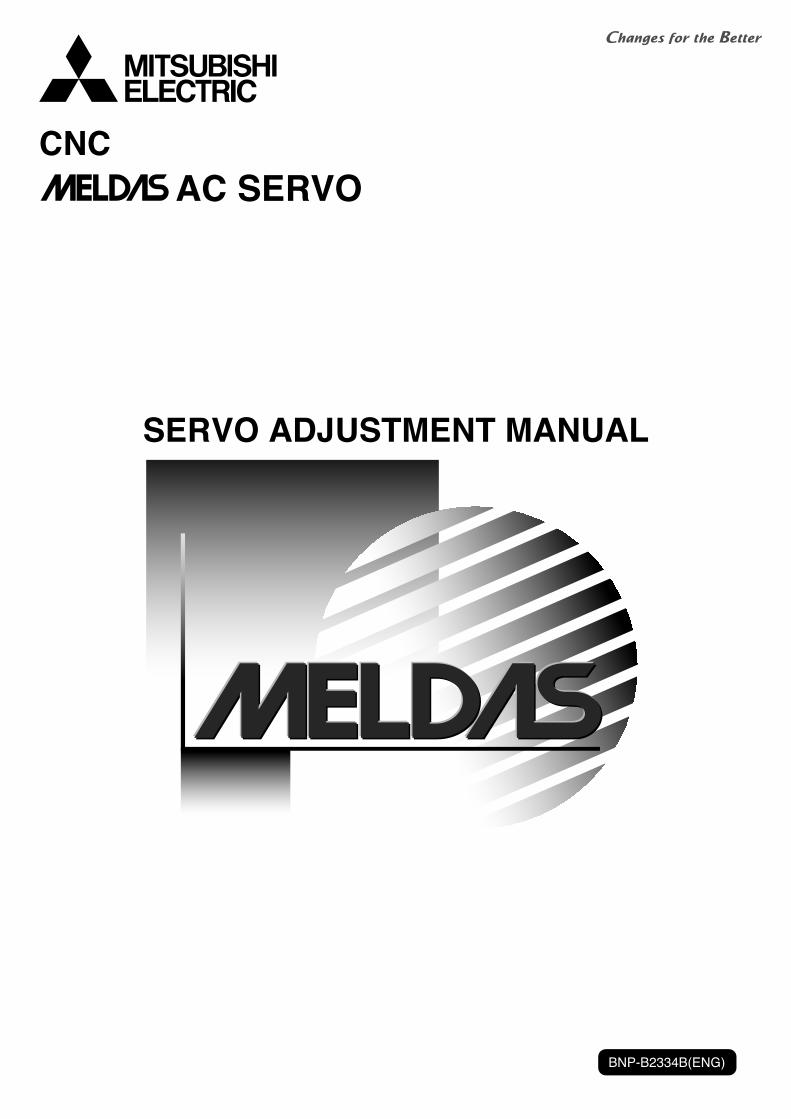
(1) Load inertia
Inertia is physical quantity to express load amount. In servo
control, load inertia converted into motor axis is more important
than load weight. Servo response is in proportion to speed loop
gain (VGN) and in inverse proportion to load inertia. It is
essential to know the load inertia amount when determining
appropriate VGN.
(2) Resonance frequency
All machines have a resonance point and the resonance of ball
screw is a serious problem for general machine tools.
Resonance has to be suppressed as it prevents VGN from being
raised.
Notch filter is installed on servo and it suppresses the resonance.
However, resonance frequency has to be set for each machine to
set parameters.
The clue to the efficient servo adjustment is recognizing
resonance frequency, suppressing resonance and raising VGN
as much as possible.
Vibration waveform
Speed loop gain (VGN)
Load inertiaServo response ∝
(Proportion)
Load inertia
1-3
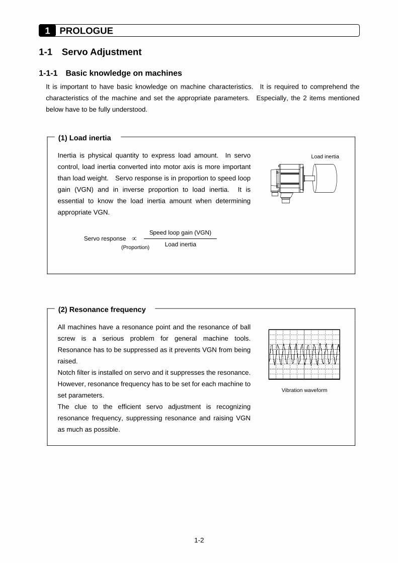
1-1-2 How to use a high-coder Before adjusting servo, it is required to understand the servo condition. Measure the D/A output
(analogue output) mounted on the servo drive unit with a high-coder etc. Get used to using a high-coder
before starting servo adjustment.
Prepare the cable SH21 (NC bus cable, etc.) and the tools shown below in advance. Relay terminal
(MR-J2CN3TM) is a tool designated for MDS-B-SVJ2 and MR-J2-CT. In case that DO output has already
been used, let the signal go through to encourage the D/A output by using a relay terminal as the D/A
output, contactor and DO output for break control shares the same connector.
Have a look at the trial output in the display
when finished connecting high-coder. An
example of MDS-B-SVJ2 is shown the right.
MR-J2CN3TM (Relay terminal)
SH21 (NC bus cable)
Waveform of MDS-B-SVJ2 trial output result
Memory Single shot Scroll
Ch.2. Trial output of rectangular waveSV062=102 SV064=0
Ch.1 Trial output of saw-tooth wave SV061=101 SV063=0
1 PROLOGUE
1-4
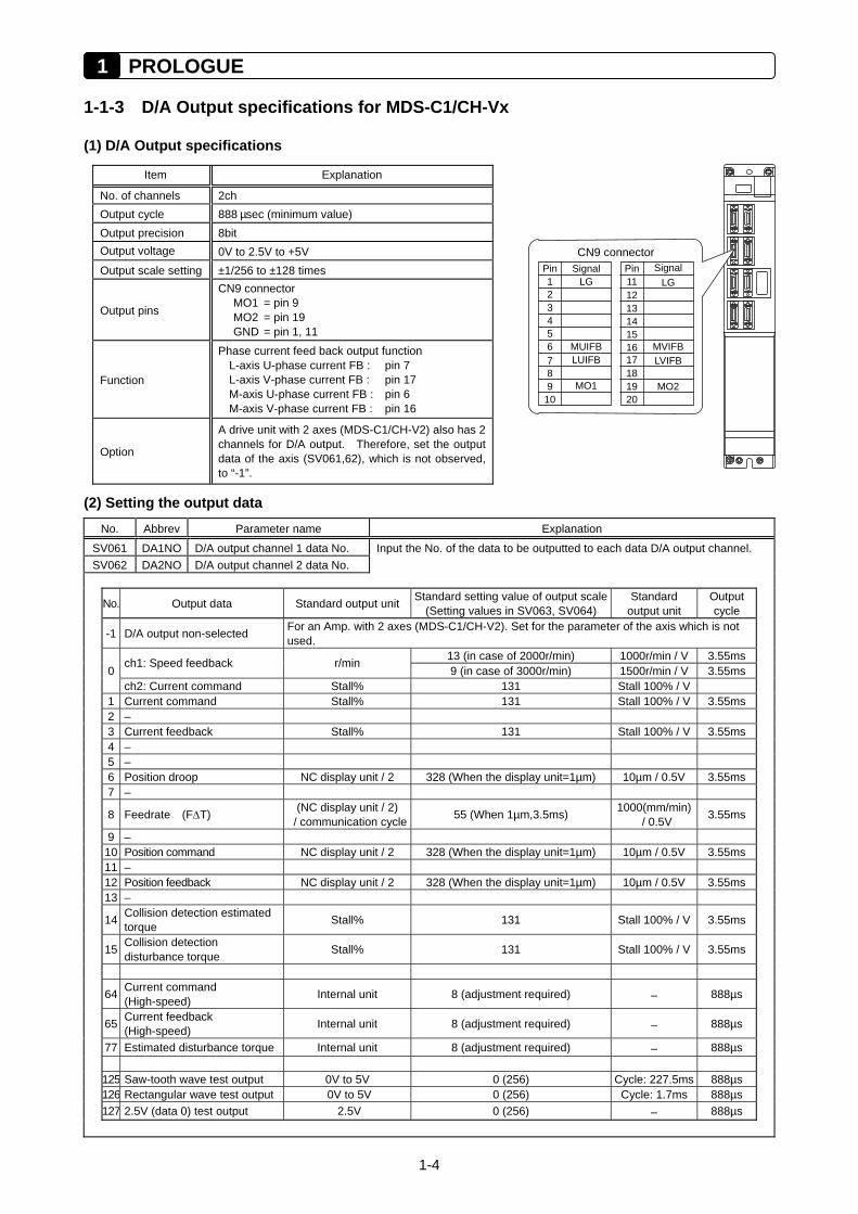
1-1-3 D/A Output specifications for MDS-C1/CH-Vx
(1) D/A Output specifications
Item Explanation
No. of channels 2ch Output cycle 888 µsec (minimum value) Output precision 8bit Output voltage 0V to 2.5V to +5V Output scale setting ±1/256 to ±128 times
Output pins
CN9 connector MO1 = pin 9 MO2 = pin 19 GND = pin 1, 11
Function
Phase current feed back output function L-axis U-phase current FB : pin 7 L-axis V-phase current FB : pin 17 M-axis U-phase current FB : pin 6 M-axis V-phase current FB : pin 16
Option
A drive unit with 2 axes (MDS-C1/CH-V2) also has 2 channels for D/A output. Therefore, set the output data of the axis (SV061,62), which is not observed, to “-1”.
(2) Setting the output data
No. Abbrev Parameter name Explanation
SV061 DA1NO D/A output channel 1 data No. Input the No. of the data to be outputted to each data D/A output channel. SV062 DA2NO D/A output channel 2 data No.
No. Output data Standard output unit Standard setting value of output scale (Setting values in SV063, SV064)
Standard output unit
Output cycle
-1 D/A output non-selected For an Amp. with 2 axes (MDS-C1/CH-V2). Set for the parameter of the axis which is not used.
13 (in case of 2000r/min) 1000r/min / V 3.55ms 0
ch1: Speed feedback r/min 9 (in case of 3000r/min) 1500r/min / V 3.55ms
ch2: Current command Stall% 131 Stall 100% / V 1 Current command Stall% 131 Stall 100% / V 3.55ms 2 – 3 Current feedback Stall% 131 Stall 100% / V 3.55ms 4 – 5 – 6 Position droop NC display unit / 2 328 (When the display unit=1µm) 10µm / 0.5V 3.55ms 7 –
8 Feedrate (F∆T) (NC display unit / 2) / communication cycle 55 (When 1µm,3.5ms) 1000(mm/min)
/ 0.5V 3.55ms
9 – 10 Position command NC display unit / 2 328 (When the display unit=1µm) 10µm / 0.5V 3.55ms 11 – 12 Position feedback NC display unit / 2 328 (When the display unit=1µm) 10µm / 0.5V 3.55ms 13 –
14 Collision detection estimated torque Stall% 131 Stall 100% / V 3.55ms
15 Collision detection disturbance torque Stall% 131 Stall 100% / V 3.55ms
64 Current command (High-speed) Internal unit 8 (adjustment required) – 888µs
65 Current feedback (High-speed) Internal unit 8 (adjustment required) – 888µs
77 Estimated disturbance torque Internal unit 8 (adjustment required) – 888µs 125 Saw-tooth wave test output 0V to 5V 0 (256) Cycle: 227.5ms 888µs 126 Rectangular wave test output 0V to 5V 0 (256) Cycle: 1.7ms 888µs 127 2.5V (data 0) test output 2.5V 0 (256) – 888µs
MO19
Signal
LG
LUIFBMUIFB
2
5
1Pin
6
43
10
78
CN9 connector
MO2 19
Signal
LG
LVIFB MVIFB
12
15
11 Pin
16
14 13
20
17 18
1-5
(3) Setting the output scale
Usually, the standard setting value is set for the output scale (SV063, SV064). When “0” is set, the output
will be made as well as when “256” is set.
SV063 5 [V]
DATA × 256
× 256 (8bit)
+ 2.5 [V] (offset) = Output voltage [V]
(Example) When outputting the current FB with 100%/V–stall (SV061=3, SV063=131)
131 5
100 × 256
× 256
+ 2.5 = 3.499 [V]
No. Abbrev. Parameter name Explanation Normal setting range
SV063 DA1MPY D/A output channel 1 output scale
-32768 to 32767
SV064 DA2MPY D/A output channel 2 output scale
The standard setting value is specified usually. (When “0” is set, the output will be made as well as when “256” is set)
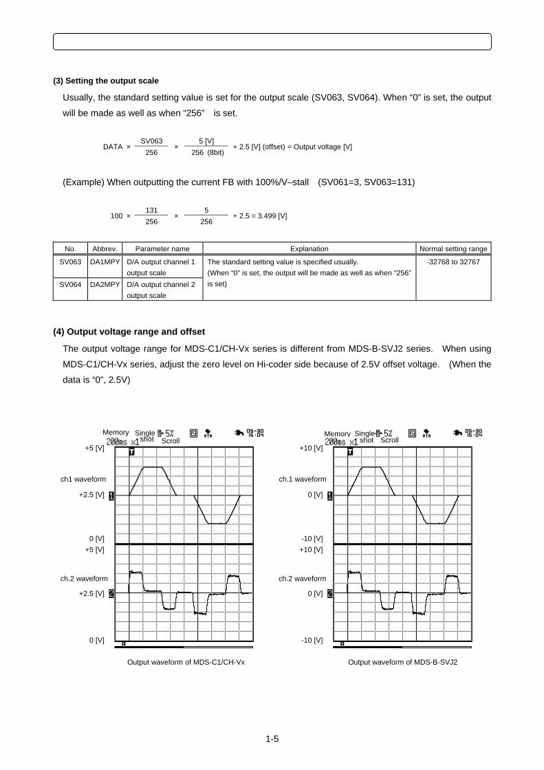
(4) Output voltage range and offset
The output voltage range for MDS-C1/CH-Vx series is different from MDS-B-SVJ2 series. When using
MDS-C1/CH-Vx series, adjust the zero level on Hi-coder side because of 2.5V offset voltage. (When the
data is “0”, 2.5V)
Memory Single shot Scroll
+2.5 [V]
Output waveform of MDS-C1/CH-Vx
+5 [V]
0 [V]
+2.5 [V]
+5 [V]
0 [V]
ch1 waveform
ch.2 waveform
Memory Single shot Scroll
0 [V]
Output waveform of MDS-B-SVJ2
+10 [V]
-10 [V]
0 [V]
+10 [V]
-10 [V]
ch.1 waveform
ch.2 waveform
1 PROLOGUE
1-6
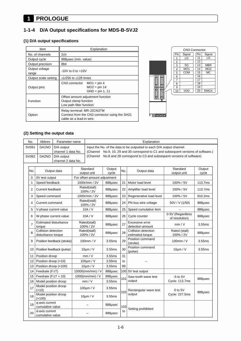
1-1-4 D/A Output specifications for MDS-B-SVJ2
(1) D/A output specifications
Item Explanation No. of channels 2ch Output cycle 888µsec (min. value) Output precision 8bit Output voltage range
-10V to 0 to +10V
Output scale setting ±1/256 to ±128 times
Output pins CN3 connector MO1 = pin 4 MO2 = pin 14 GND = pin 1, 11
Function Offset amount adjustment function Output clamp function Low path filter function
Option Relay terminal: MR-J2CN3TM Connect from the CN3 connector using the SH21 cable as a lead-in wire.
(2) Setting the output data
No. Abbrev Parameter name Explanation
SV061 DA1NO D/A output channel 1 data No.
SV062 DA2NO D/A output channel 2 data No.
Input the No. of the data to be outputted to each D/A output channel. (Channel No.9, 10, 29 and 30 correspond to C1 and subsequent versions of software.) (Channel No.8 and 28 correspond to C3 and subsequent versions of software)
No. Output data Standard output unit
Output cycle No. Output data Standard
output unit Output cycle
0 0V test output For offset amount adjustment 1 Speed feedback 1000r/min / 2V 888µsec 21 Motor load level 100% / 5V 113.7ms
2 Current feedback Rated(stall) 100% / 2V 888µsec 22 Amplifier load level 100% / 5V 113.7ms
3 Speed command 1000r/min / 2V 888µsec 23 Regenerative load level 100% / 5V 910.2ms
4 Current command Rated(stall) 100% / 2V 888µsec 24 PN bus wire voltage 50V / V (1/50) 888µsec
5 V-phase current value 10A / V 888µsec 25 Speed cumulative item – 888µsec
6 W-phase current-value 10A / V 888µsec 26 Cycle counter 0-5V (Regardless of resolution) 888µsec
7 Estimated disturbance torque
Rated(stall) 100% / 2V 888µsec 27 Excessive error
detection amount mm / V 3.55ms
8 Collision detection disturbance torque
Rated(stall) 100% / 2V 888µsec 28 Collision detection
estimated torque Rated (stall) 100% / 2V 888µsec
9 Position feedback (stroke) 100mm / V 3.55ms 29 Position command (stroke) 100mm / V 3.55ms
10 Position feedback (pulse) 10µm / V 3.55ms 30 Position command (pulse) 10µm / V 3.55ms
11 Position droop mm / V 3.55ms 31 12 Position droop (×10) 100µm / V 3.55ms to – 13 Position droop (×100) 10µm / V 3.55ms 99 14 Feedrate (F∆T) 10000(mm/min) / V 888µsec 100 5V test output 15 Feedrate (F∆T × 10) 1000(mm/min) / V 888µsec -5 to 5V 16 Model position droop mm / V 3.55ms
101 Saw-tooth wave test output Cycle: 113.7ms
888µsec
17 Model position droop (×10) 100µm / V 3.55ms 0 to 5V
18 Model position droop (×100) 10µm / V 3.55ms
102 Rectangular wave test output Cycle: 227.5ms
888µsec
19 q-axis current cumulative value – 888µsec 103
20 d-axis current cumulative value – 888µsec to
Setting prohibited
9
Signal
MO1
LG
COM
SG
2
VDD
5
1 Pin
6
4 3
10
7 8
CN3 Connector
19
Signal
MO2
LG
MC
MBR
12
EMGX
15
11Pin
16
1413
20
1718
1-7
(3) Setting the output scale
This is set when an output is to be made with a unit other than the standard output unit.
(Example 1) When SV061 = 5, SV063 = 2560
The V-phase current value will be output with 1 A/V unit to D/A output ch.1.
(Example 2) When SV063 = 11, SV064 = 128
The position droop will be output with a 2mm/Vunit to D/A output ch.2.
No. Abbrev. Parameter name Explanation Normal setting range
SV063 DA1MPY D/A output channel 1 output scale
-32768 to 32767
SV064 DA2MPY D/A output channel 2 output scale
When “0” is set, the output will be made with the standard output unit. To change the output unit, set a value other than 0. The scale is set with a 1/256 unit. When 256 is set, the unit will be the same as the standard output.
(4) Setting the offset amount
This is used when the zero level of the output voltage is to be finely adjusted. The output scale when the
data No. is “0” will be the offset amount. After setting the offset, set the data No. to a value other than “0”,
and do not set it to “0” again. Because the offset amount is saved in the drive unit memory, it does not
need to be set again when the drive unit power is turned ON next.
No. Abbrev. Parameter name Explanation Normal setting range
SV061 DA1NO D/A output channel 1 data No.
0 to 102
SV062 DA2NO D/A output channel 2 data No.
Set “0”. After setting the offset amount in SV063 and SV064, change the data No. to a value other than “0”.
SV063 DA1MPY D/A output channel 1 offset amount
-10 to 10
SV064 DA2MPY D/A output channel 2 offset amount
The amount can be set with the output precision unit. Observe the output value and set so that the output value is 0V. Because the offset amount is saved in the drive unit memory, it does not need to be set again when the drive unit power is turned ON next.
1 PROLOGUE
1-8
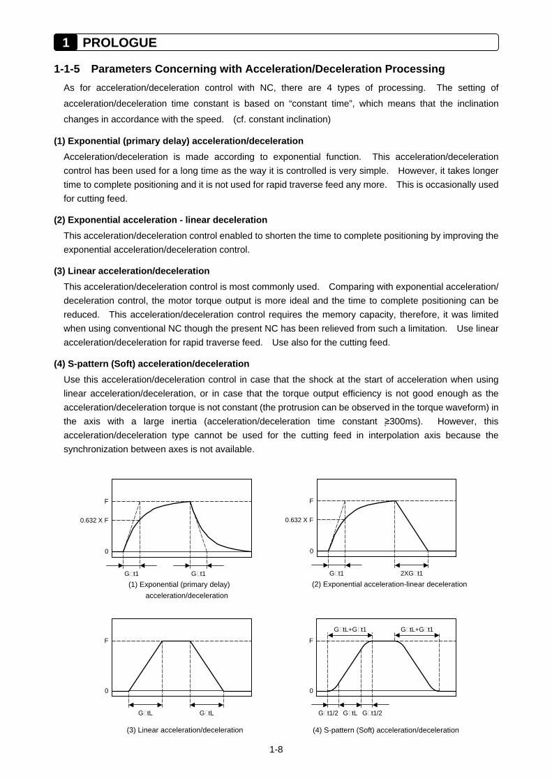
1-1-5 Parameters Concerning with Acceleration/Deceleration Processing As for acceleration/deceleration control with NC, there are 4 types of processing. The setting of
acceleration/deceleration time constant is based on “constant time”, which means that the inclination
changes in accordance with the speed. (cf. constant inclination)
(1) Exponential (primary delay) acceleration/deceleration Acceleration/deceleration is made according to exponential function. This acceleration/deceleration control has been used for a long time as the way it is controlled is very simple. However, it takes longer time to complete positioning and it is not used for rapid traverse feed any more. This is occasionally used for cutting feed.
(2) Exponential acceleration - linear deceleration This acceleration/deceleration control enabled to shorten the time to complete positioning by improving the exponential acceleration/deceleration control.
(3) Linear acceleration/deceleration This acceleration/deceleration control is most commonly used. Comparing with exponential acceleration/ deceleration control, the motor torque output is more ideal and the time to complete positioning can be reduced. This acceleration/deceleration control requires the memory capacity, therefore, it was limited when using conventional NC though the present NC has been relieved from such a limitation. Use linear acceleration/deceleration for rapid traverse feed. Use also for the cutting feed.
(4) S-pattern (Soft) acceleration/deceleration Use this acceleration/deceleration control in case that the shock at the start of acceleration when using linear acceleration/deceleration, or in case that the torque output efficiency is not good enough as the acceleration/deceleration torque is not constant (the protrusion can be observed in the torque waveform) in the axis with a large inertia (acceleration/deceleration time constant ≥300ms). However, this acceleration/deceleration type cannot be used for the cutting feed in interpolation axis because the synchronization between axes is not available.
(2) Exponential acceleration-linear deceleration
F
G t1
0
0.632 X F
2XG t1
(3) Linear acceleration/deceleration
G tL
0
G tL
F
(4) S-pattern (Soft) acceleration/deceleration
F
G tL G t1/2
G tL+G t1
0
G t1/2
G tL+G t1
(1) Exponential (primary delay)
F
G t1
0
0.632 X F
G t1
acceleration/deceleration
1-9
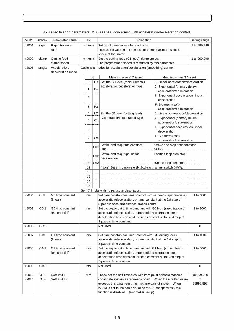
Axis specification parameters (M60S series) concerning with acceleration/deceleration control.
M60S Abbrev. Parameter name Unit Explanation Setting range
#2001 rapid Rapid traverse rate
mm/min Set rapid traverse rate for each axis. The setting value has to be less than the maximum spindle speed of the motor.
1 to 999,999
#2002 clamp Cutting feed clamp speed
mm/min Set the cutting feed (G1 feed) clamp speed. The programmed speed is restricted by this parameter.
1 to 999,999
Designate modes for acceleration/deceleration (smoothing) control;
bit Meaning when “0” is set. Meaning when “1” is set. 0 LR 1: Linear acceleration/deceleration
1 R12: Exponential (primary delay)
acceleration/deceleration
2 8: Exponential acceleration, linear
deceleration
3 R3
Set the G0 feed (rapid traverse) acceleration/deceleration type.
F: S-pattern (soft) acceleration/deceleration
4 LC 1: Linear acceleration/deceleration
5 C12: Exponential (primary delay)
acceleration/deceleration
6 8: Exponential acceleration, linear
deceleration
7 C3
Set the G1 feed (cutting feed) Acceleration/deceleration type.
F: S-pattern (soft) acceleration/deceleration
8 OT1Stroke end stop time constant G0tl
Stroke end stop time constant G0tl×2
9 OT2Stroke end stop type: linear deceleration
Position loop step stop
10 OT3 (Speed loop step stop) 11 (Note) Set this parameter(bit8-10) with a limit switch (H/W). 12 13 14 15
#2003 smgst Acceleration/ deceleration mode
Set “0” in bits with no particular description. #2004 G0tL G0 time constant
(linear) ms Set time constant for linear control with G0 feed (rapid traverse)
acceleration/deceleration, or time constant at the 1st step of S-pattern acceleration/deceleration control
1 to 4000
#2005 G0t1 G0 time constant (exponential)
ms Set the exponential time constant with G0 feed (rapid traverse) acceleration/deceleration, exponential acceleration-linear deceleration time constant, or time constant at the 2nd step of S-pattern time constant.
1 to 5000
#2006
G0t2 Not used. 0
#2007 G1tL G1 time constant (linear)
ms Set time constant for linear control with G1 (cutting feed) acceleration/deceleration, or time constant at the 1st step of S-pattern time constant.
1 to 4000
#2008
G1t1 G1 time constant (exponential)
ms Set the exponential time constant with G1 feed (cutting feed) acceleration/deceleration, exponential acceleration-linear deceleration time constant, or time constant at the 2nd step of S-pattern time constant.
1 to 5000
#2009
G1t2 ms Not used 0
#2013 #2014
OT– OT+
Soft limit I – Soft limit I +
mm These set the soft limit area with zero point of basic machine coordinate system as reference point. When the inputted value exceeds this parameter, the machine cannot move. When #2013 is set to the same value as #2014 except for “0”, this function is disabled. (For maker setup)
-99999.999to
99999.999
2-1
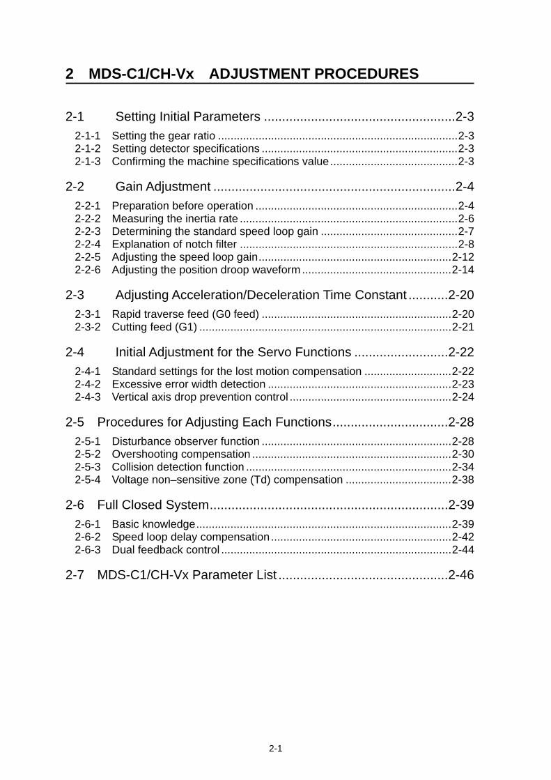
2 MDS-C1/CH-Vx ADJUSTMENT PROCEDURES
2-1 Setting Initial Parameters .....................................................2-3
2-1-1 Setting the gear ratio .............................................................................2-3 2-1-2 Setting detector specifications ...............................................................2-3 2-1-3 Confirming the machine specifications value.........................................2-3
2-2 Gain Adjustment ...................................................................2-4
2-2-1 Preparation before operation .................................................................2-4 2-2-2 Measuring the inertia rate ......................................................................2-6 2-2-3 Determining the standard speed loop gain ............................................2-7 2-2-4 Explanation of notch filter ......................................................................2-8 2-2-5 Adjusting the speed loop gain..............................................................2-12 2-2-6 Adjusting the position droop waveform ................................................2-14
2-3 Adjusting Acceleration/Deceleration Time Constant ...........2-20
2-3-1 Rapid traverse feed (G0 feed) .............................................................2-20 2-3-2 Cutting feed (G1) .................................................................................2-21
2-4 Initial Adjustment for the Servo Functions ..........................2-22
2-4-1 Standard settings for the lost motion compensation ............................2-22 2-4-2 Excessive error width detection ...........................................................2-23 2-4-3 Vertical axis drop prevention control ....................................................2-24
2-5 Procedures for Adjusting Each Functions................................2-28 2-5-1 Disturbance observer function .............................................................2-28 2-5-2 Overshooting compensation ................................................................2-30 2-5-3 Collision detection function ..................................................................2-34 2-5-4 Voltage non–sensitive zone (Td) compensation ..................................2-38
2-6 Full Closed System..................................................................2-39 2-6-1 Basic knowledge..................................................................................2-39 2-6-2 Speed loop delay compensation..........................................................2-42 2-6-3 Dual feedback control ..........................................................................2-44
2-7 MDS-C1/CH-Vx Parameter List ...............................................2-46
2 MDS-C1/CH-Vx ADJUSTMENT PROCEDURES
2-2
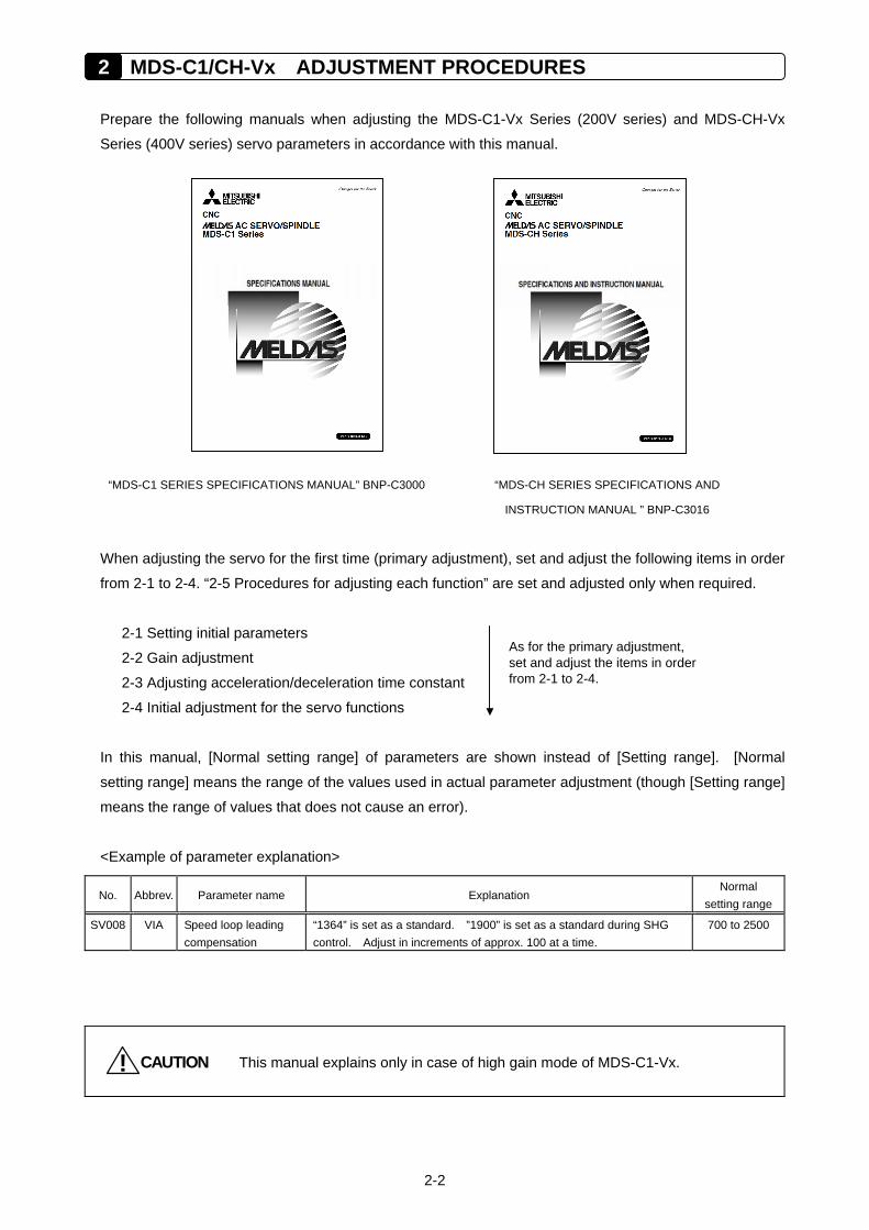
Prepare the following manuals when adjusting the MDS-C1-Vx Series (200V series) and MDS-CH-Vx
Series (400V series) servo parameters in accordance with this manual.
“MDS-C1 SERIES SPECIFICATIONS MANUAL” BNP-C3000 “MDS-CH SERIES SPECIFICATIONS AND
INSTRUCTION MANUAL ” BNP-C3016
When adjusting the servo for the first time (primary adjustment), set and adjust the following items in order
from 2-1 to 2-4. “2-5 Procedures for adjusting each function” are set and adjusted only when required.
2-1 Setting initial parameters
2-2 Gain adjustment
2-3 Adjusting acceleration/deceleration time constant
2-4 Initial adjustment for the servo functions
In this manual, [Normal setting range] of parameters are shown instead of [Setting range]. [Normal
setting range] means the range of the values used in actual parameter adjustment (though [Setting range]
means the range of values that does not cause an error).
<Example of parameter explanation>
No. Abbrev. Parameter name Explanation Normal
setting range
SV008 VIA Speed loop leading compensation
“1364” is set as a standard. ”1900” is set as a standard during SHG control. Adjust in increments of approx. 100 at a time.
700 to 2500
CAUTION! This manual explains only in case of high gain mode of MDS-C1-Vx.
As for the primary adjustment, set and adjust the items in order from 2-1 to 2-4.
2-3
2-1 Setting Initial Parameters Input the setting values listed in the "Standard Parameter list per motor" in the specifications manual for
the initial parameters before adjusting the servo. If a wrong value is input, the initial parameter error
(ALM37) will occur. In this case, the parameter number causing an error is displayed on the NC screen.
Some parameters are determined by the machine specification and they are explained below.
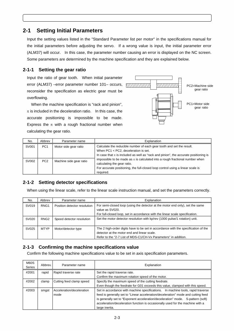
2-1-1 Setting the gear ratio Input the ratio of gear tooth. When initial parameter
error (ALM37) –error parameter number 101– occurs,
reconsider the specification as electric gear must be
overflowing.
When the machine specification is “rack and pinion”,
π is included in the deceleration ratio. In this case, the
accurate positioning is impossible to be made.
Express the π with a rough fractional number when
calculating the gear ratio. No. Abbrev Parameter name Explanation
SV001
PC1 Motor side gear ratio
SV002
PC2 Machine side gear ratio
Calculate the reducible number of each gear tooth and set the result. When PC1 < PC2, deceleration is set. In case that π is included as well as “rack and pinion”, the accurate positioning is impossible to be made as π is calculated into a rough fractional number when calculating the gear ratio. For accurate positioning, the full-closed loop control using a linear scale is required.
2-1-2 Setting detector specifications When using the linear scale, refer to the linear scale instruction manual, and set the parameters correctly. No. Abbrev Parameter name Explanation
SV019 RNG1 Position detector resolution For semi-closed loop (using the detector at the motor end only), set the same value as SV020. For full-closed loop, set in accordance with the linear scale specification.
SV020
RNG2 Speed detector resolution Set the motor detector resolution with kp/rev (1000 pulse/1 rotation) unit.
SV025
MTYP Motor/detector type The 2 high-order digits have to be set in accordance with the specification of the detector at the motor end and linear scale. Refer to the "2-7 List of MDS-C1/CH-Vx Parameters" in addition.
2-1-3 Confirming the machine specifications value Confirm the following machine specifications value to be set in axis specification parameters. M60S Series
Abbrev. Parameter name Explanation
#2001 rapid Rapid traverse rate Set the rapid traverse rate. Confirm the maximum rotation speed of the motor.
#2002 clamp Cutting feed clamp speed Specify the maximum speed of the cutting feedrate. Even though the feedrate for G01 exceeds this value, clamped with this speed.
#2003 smgst Acceleration/deceleration mode
Set in accordance with machine specifications. In machine tools, rapid traverse feed is generally set to “Linear acceleration/deceleration” mode and cutting feed is generally set to “Exponent acceleration/deceleration” mode. S-pattern (soft) acceleration/deceleration function is occasionally used for the machine with a large inertia.
PC1=Motor side gear ratio
PC2=Machine side gear ratio
2 MDS-C1/CH-Vx ADJUSTMENT PROCEDURES
2-4
2-2 Gain Adjustment
2-2-1 Preparation before operation
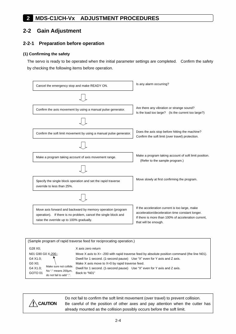
(1) Confirming the safety
The servo is ready to be operated when the initial parameter settings are completed. Confirm the safety
by checking the following items before operation.
CAUTION!
Do not fail to confirm the soft limit movement (over travel) to prevent collision. Be careful of the position of other axes and pay attention when the cutter has already mounted as the collision possibly occurs before the soft limit.
(Sample program of rapid traverse feed for reciprocating operation.)
G28 X0; X axis zero return
N01 G90 G0 X-200.; Move X axis to X= -200 with rapid traverse feed by absolute position command (the line N01).G4 X1.0; Dwell for 1 second. (1-second pause) Use “X” even for Y axis and Z axis. G0 X0; Make X axis move to X=0 by rapid traverse feed. G4 X1.0; Dwell for 1 second. (1-second pause) Use “X” even for Y axis and Z axis. GOTO 01 Back to “N01”
Make sure not collide. No “.” means 200µm, do not fail to add “.”.
Confirm the axis movement by using a manual pulse generator.
Cancel the emergency stop and make READY ON.
Confirm the soft limit movement by using a manual pulse generator.
Specify the single block operation and set the rapid traverse override to less than 25%.
Move axis forward and backward by memory operation (program operation). If there is no problem, cancel the single block and raise the override up to 100% gradually.
Make a program taking account of axis movement range.
Is any alarm occurring?
Are there any vibration or strange sound? Is the load too large? (Is the current too large?)
Does the axis stop before hitting the machine? Confirm the soft limit (over travel) protection.
Make a program taking account of soft limit position.(Refer to the sample program.)
If the acceleration current is too large, make acceleration/deceleration time constant longer. If there is more than 100% of acceleration current, that will be enough.
Move slowly at first confirming the program.
2-5
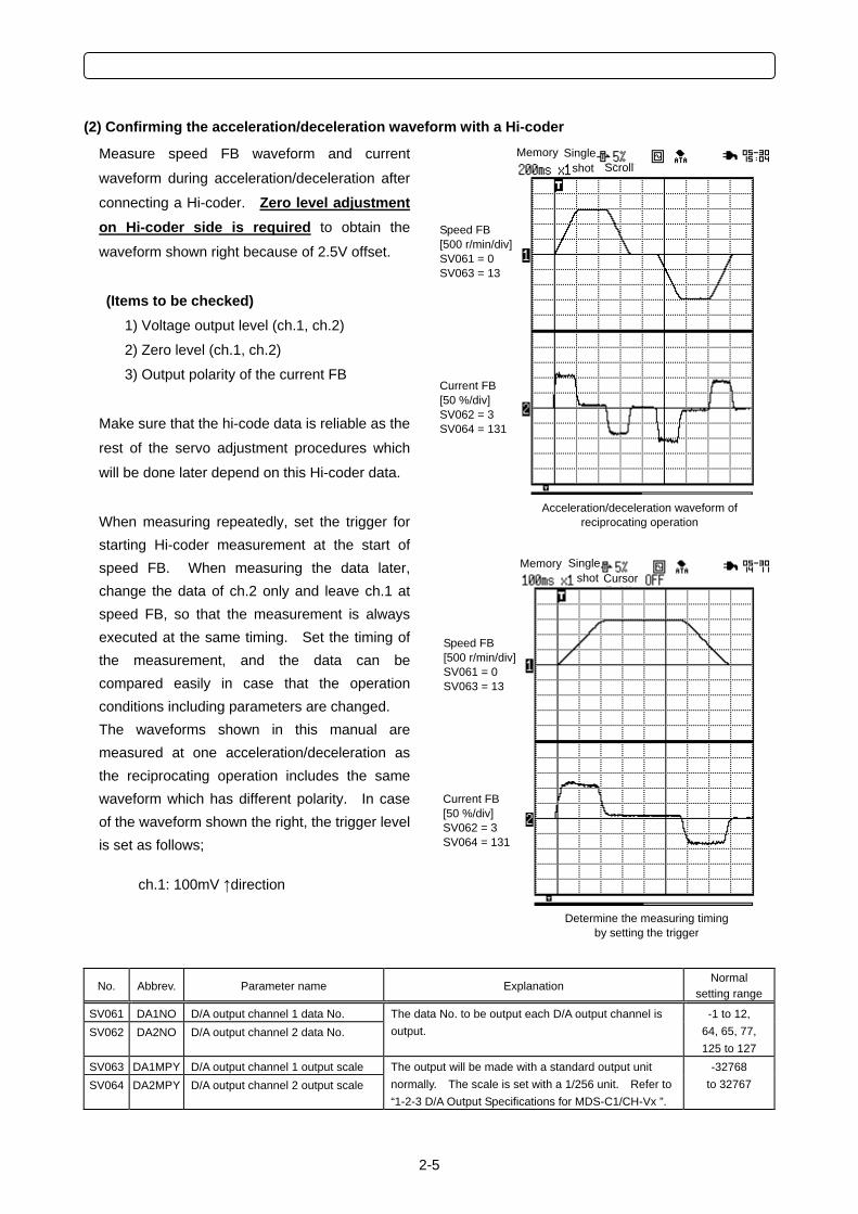
(2) Confirming the acceleration/deceleration waveform with a Hi-coder
Measure speed FB waveform and current
waveform during acceleration/deceleration after
connecting a Hi-coder. Zero level adjustment on Hi-coder side is required to obtain the
waveform shown right because of 2.5V offset.
(Items to be checked) 1) Voltage output level (ch.1, ch.2)
2) Zero level (ch.1, ch.2)
3) Output polarity of the current FB
Make sure that the hi-code data is reliable as the
rest of the servo adjustment procedures which
will be done later depend on this Hi-coder data.
When measuring repeatedly, set the trigger for starting Hi-coder measurement at the start of speed FB. When measuring the data later, change the data of ch.2 only and leave ch.1 at speed FB, so that the measurement is always executed at the same timing. Set the timing of the measurement, and the data can be compared easily in case that the operation conditions including parameters are changed. The waveforms shown in this manual are measured at one acceleration/deceleration as the reciprocating operation includes the same waveform which has different polarity. In case of the waveform shown the right, the trigger level is set as follows;
ch.1: 100mV ↑direction
No. Abbrev. Parameter name Explanation Normal
setting range
SV061 DA1NO D/A output channel 1 data No. SV062 DA2NO D/A output channel 2 data No.
The data No. to be output each D/A output channel is output.
-1 to 12, 64, 65, 77, 125 to 127
SV063 DA1MPY D/A output channel 1 output scale SV064 DA2MPY D/A output channel 2 output scale
The output will be made with a standard output unit normally. The scale is set with a 1/256 unit. Refer to “1-2-3 D/A Output Specifications for MDS-C1/CH-Vx ”.
-32768 to 32767
Speed FB [500 r/min/div] SV061 = 0 SV063 = 13
Current FB [50 %/div] SV062 = 3 SV064 = 131
Memory Single shot Cursor
Determine the measuring timing by setting the trigger
Memory Singleshot Scroll
Acceleration/deceleration waveform of reciprocating operation
Speed FB [500 r/min/div] SV061 = 0 SV063 = 13
Current FB [50 %/div] SV062 = 3 SV064 = 131
2 MDS-C1/CH-Vx ADJUSTMENT PROCEDURES
2-6
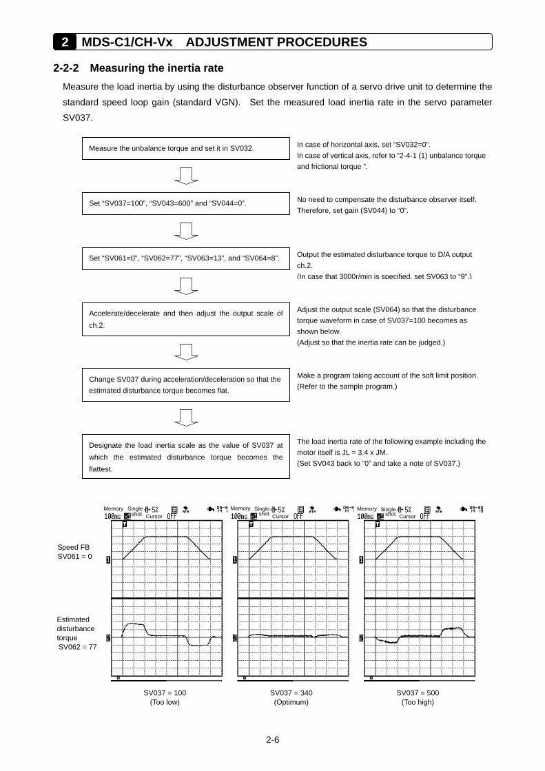
2-2-2 Measuring the inertia rate Measure the load inertia by using the disturbance observer function of a servo drive unit to determine the
standard speed loop gain (standard VGN). Set the measured load inertia rate in the servo parameter
SV037.
Measure the unbalance torque and set it in SV032.
Set “SV037=100”, “SV043=600” and “SV044=0”.
In case of horizontal axis, set “SV032=0”. In case of vertical axis, refer to “2-4-1 (1) unbalance torqueand frictional torque ”.
No need to compensate the disturbance observer itself. Therefore, set gain (SV044) to “0”.
Set “SV061=0”, “SV062=77”, “SV063=13”, and “SV064=8”. Output the estimated disturbance torque to D/A output ch.2. (In case that 3000r/min is specified, set SV063 to “9”.)
Change SV037 during acceleration/deceleration so that theestimated disturbance torque becomes flat.
Make a program taking account of the soft limit position.(Refer to the sample program.)
Designate the load inertia scale as the value of SV037 atwhich the estimated disturbance torque becomes theflattest.
The load inertia rate of the following example including themotor itself is JL = 3.4 x JM. (Set SV043 back to “0” and take a note of SV037.)
Accelerate/decelerate and then adjust the output scale ofch.2.
Adjust the output scale (SV064) so that the disturbance torque waveform in case of SV037=100 becomes as shown below. (Adjust so that the inertia rate can be judged.)
Speed FB SV061 = 0
SV037 = 100 (Too low)
SV037 = 340 (Optimum)
SV037 = 500 (Too high)
Memory Single shot Cursor
Memory Single shot Cursor
Memory Single shot Cursor
Estimated disturbance torque SV062 = 77
2-7
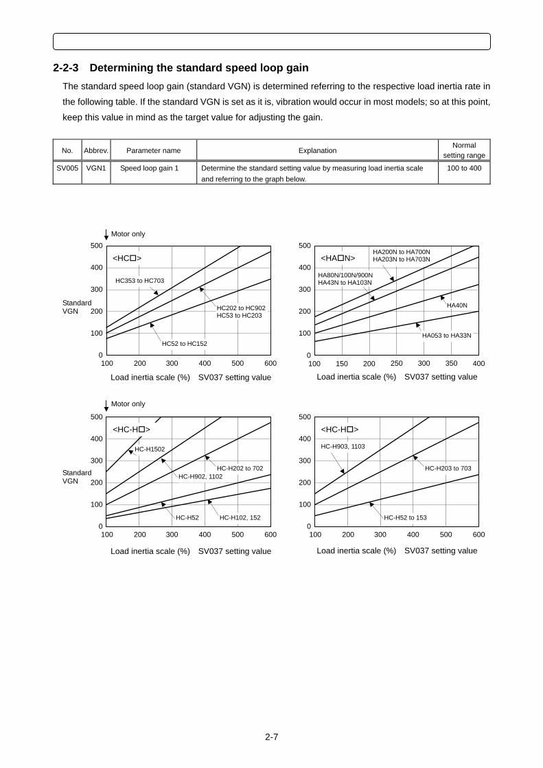
2-2-3 Determining the standard speed loop gain The standard speed loop gain (standard VGN) is determined referring to the respective load inertia rate in
the following table. If the standard VGN is set as it is, vibration would occur in most models; so at this point,
keep this value in mind as the target value for adjusting the gain.
No. Abbrev. Parameter name Explanation Normal
setting range
SV005 VGN1 Speed loop gain 1 Determine the standard setting value by measuring load inertia scale and referring to the graph below.
100 to 400
100
200
0
500
400
300
100 200 400 600 300 500
HC52 to HC152
HC202 to HC902HC53 to HC203
<HC >
HC353 to HC703
100
200
0
500
400
300
100 200 400 600 300 500
<HC-H >
HC-H52 to 153
HC-H203 to 703
HC-H903, 1103
100
200
0
500
400
300
100 200 400 600 300 500
HC-H102, 152HC-H52
HC-H202 to 702HC-H902, 1102
HC-H1502
<HC-H >
100
200
0
500
400
300
100 200 300 400 150 250 350
HA40N
HA80N/100N/900NHA43N to HA103N
<HA N>
HA053 to HA33N
HA200N to HA700N HA203N to HA703N
Load inertia scale (%) SV037 setting value
Standard VGN
Motor only
Load inertia scale (%) SV037 setting value
Load inertia scale (%) SV037 setting value
Standard VGN
Motor only
Load inertia scale (%) SV037 setting value
2 MDS-C1/CH-Vx ADJUSTMENT PROCEDURES
2-8
2-2-4 Explanation of notch filter Machine resonance occurs when the speed loop gain is increased to improve the control accuracy. The
machine resonance is a phenomenon that occurs when the servo's speed loop control acts on the
machine's specific frequency (characteristic resonance frequency). When adjusting the speed loop gain, a
notch filter must be set to suppress this machine resonance (vibration) resulting in an increase of vibration.
The notch filter functions to suppress the servo response at the set frequency, and thereby suppress the
occurrence of vibration. Always understand the methods of setting the notch filter before adjusting the
speed loop gain. Refer to section "2-2-5 Adjusting the speed loop gain" for details on setting the notch
filter.
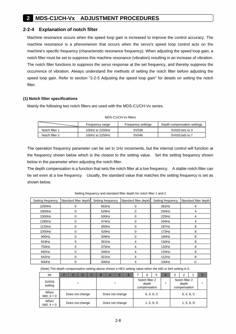
(1) Notch filter specifications
Mainly the following two notch filters are used with the MDS-C1/CH-Vx series.
MDS-C1/CH-Vx filters
Frequency range Frequency settings Depth compensation settings
Notch filter 1 100Hz to 2250Hz SV038 SV033.bit1 to 3 Notch filter 2 100Hz to 2250Hz SV046 SV033.bit5 to 7
The operation frequency parameter can be set in 1Hz increments, but the internal control will function at
the frequency shown below which is the closest to the setting value. Set the setting frequency shown
below in the parameter when adjusting the notch filter.
The depth compensation is a function that sets the notch filter at a low frequency. A stable notch filter can
be set even at a low frequency. Usually, the standard value that matches the setting frequency is set as
shown below.
Setting frequency and standard filter depth for notch filter 1 and 2
Setting frequency Standard filter depth Setting frequency Standard filter depth Setting frequency Standard filter depth
2250Hz 0 562Hz 0 281Hz 4 1800Hz 0 529Hz 0 250Hz 4 1500Hz 0 500Hz 0 225Hz 4 1285Hz 0 474Hz 0 204Hz 4 1125Hz 0 450Hz 0 187Hz 8 1000Hz 0 429Hz 0 173Hz 8 900Hz 0 409Hz 0 160Hz 8 818Hz 0 391Hz 4 150Hz 8 750Hz 0 375Hz 4 132Hz 8 692Hz 0 346Hz 4 125Hz 8 642Hz 0 321Hz 4 112Hz 8 600Hz 0 300Hz 4 100Hz C
(Note) The depth compensation setting above shows a HEX setting value when the bit0 or bit4 setting is 0.
bit F E D C B A 9 8 7 6 5 4 3 2 1 0
SV033 setting * *
Notch filter 2 depth
compensation *
Notch filter 2 depth
compensation *
When bit0, 4 = 0 Does not change Does not change 0, 4, 8, C 0, 4, 8, C
When bit0, 4 = 0 Does not change Does not change 1, 5, 9, D 1, 5, 9, D
2-9
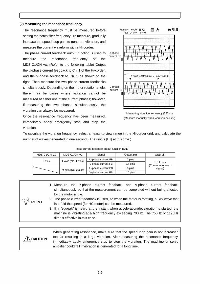
(2) Measuring the resonance frequency
The resonance frequency must be measured before
setting the notch filter frequency. To measure, gradually
increase the speed loop gain to generate vibration, and
measure the current waveform with a Hi-corder.
The phase current feedback output function is used to
measure the resonance frequency of the
MDS-C1/CH-Vx. (Refer to the following table) Output
the U-phase current feedback to Ch. 1 of the Hi-corder,
and the V-phase feedback to Ch. 2 as shown on the
right. Then measure the two phase current feedbacks
simultaneously. Depending on the motor rotation angle,
there may be cases where vibration cannot be
measured at either one of the current phases; however,
if measuring the two phases simultaneously, the
vibration can always be measured.
Once the resonance frequency has been measured,
immediately apply emergency stop and stop the
vibration.
To calculate the vibration frequency, select an easy-to-view range in the Hi-corder grid, and calculate the
number of waves generated in one second. (The unit is [Hz] at this time.)
Phase current feedback output function (CN9)
MDS-C1/CH-V1 MDS-C1/CH-V2 Signal Output pin GND pin
U-phase current FB 7 pins L axis L axis (No. 1 axis)V-phase current FB 17 pins U-phase current FB 6 pins M axis (No. 2 axis)V-phase current FB 16 pins
1, 11 pins (Common for each
signal)
POINT
1. Measure the Y-phase current feedback and V-phase current feedback simultaneously so that the measurement can be completed without being affected by the motor angle.
2. The phase current feedback is used, so when the motor is rotating, a SIN wave that is 4-fold the speed (for HC motor) can be measured.
3. If a "squeak" is heard at the instant when acceleration/deceleration is started, the machine is vibrating at a high frequency exceeding 700Hz. The 750Hz or 1125Hz filter is effective in this case.
CAUTION!
When generating resonance, make sure that the speed loop gain is not increased too far resulting in a large vibration. After measuring the resonance frequency, immediately apply emergency stop to stop the vibration. The machine or servo amplifier could fail if vibration is generated for a long time.
Measuring vibration frequency (233Hz)
(Measure manually when vibration occurs.)
U-phase current FB
7 wave length/30ms: 7÷0.03=233Hz
Memory Singleshot Scroll
V-phase current FB
2 MDS-C1/CH-Vx ADJUSTMENT PROCEDURES
2-10
(3) Setting the notch filter frequency
After measuring the resonance frequency, refer to the "Setting frequency and standard filter depth for
notch filter 1 and 2". Select the setting frequency larger than but closest to the resonance frequency and
set the parameter. Set the depth compensation parameter to the standard filter depth that matches the
frequency.
In the example of measurement on the previous page, the measured resonance frequency is 233Hz. Thus,
set the following:
Filter setting frequency = 250Hz, Filter depth = 4
POINT
The notch filter easily becomes unstable when a low frequency is set. Even when set, only the resonance frequency may change (the vibration tone changes), and the resonance may not be completely removed. If the state is unstable, try using a higher frequency.
Basically, all resonance can be removed by setting the notch filter. The MDS-C1/CH-Vx series has the
following functions in addition to the notch filter. Use those as necessary.
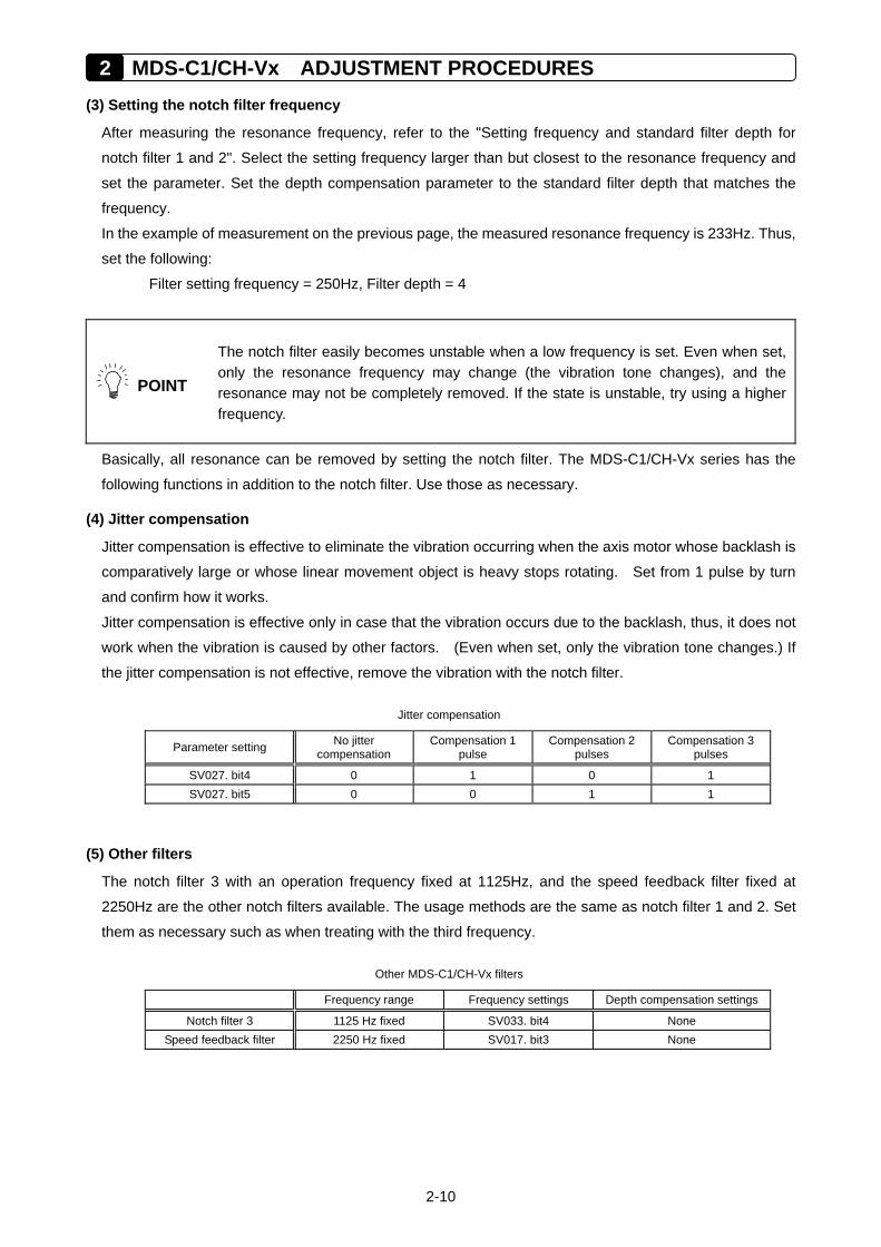
(4) Jitter compensation
Jitter compensation is effective to eliminate the vibration occurring when the axis motor whose backlash is
comparatively large or whose linear movement object is heavy stops rotating. Set from 1 pulse by turn
and confirm how it works.
Jitter compensation is effective only in case that the vibration occurs due to the backlash, thus, it does not
work when the vibration is caused by other factors. (Even when set, only the vibration tone changes.) If
the jitter compensation is not effective, remove the vibration with the notch filter.
Jitter compensation
Parameter setting No jitter compensation
Compensation 1 pulse
Compensation 2 pulses
Compensation 3 pulses
SV027. bit4 0 1 0 1 SV027. bit5 0 0 1 1
(5) Other filters
The notch filter 3 with an operation frequency fixed at 1125Hz, and the speed feedback filter fixed at
2250Hz are the other notch filters available. The usage methods are the same as notch filter 1 and 2. Set
them as necessary such as when treating with the third frequency.
Other MDS-C1/CH-Vx filters
Frequency range Frequency settings Depth compensation settings
Notch filter 3 1125 Hz fixed SV033. bit4 None Speed feedback filter 2250 Hz fixed SV017. bit3 None
2-11
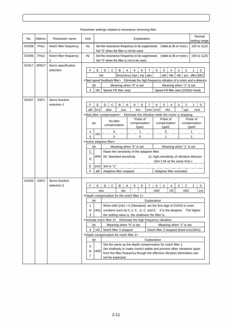
Parameter settings related to resonance removing filter
No. Abbrev. Parameter name Unit Explanation Normal
setting range
SV038 FHz1 Notch filter frequency 1
Hz Set the resonance frequency to be suppressed. (Valid at 36 or more.) Set “0” when the filter is not be used.
150 to 1125
SV046 FHz2 Notch filter frequency 2
Hz Set the resonance frequency to be suppressed. (Valid at 36 or more.) Set “0” when the filter is not to be used.
150 to 1125
SV017 SPEC*
Servo specification selection F E D C B A 9 8 7 6 5 4 3 2 1 0
mtr drva drvu mpt mp abs vdir fdir vfb qro dfbx fdir2 <Start speed feedback filter> Eliminate the high frequency vibration of a motor and a detector. bit Meaning when “0” is set Meaning when “1” is set 3 vfb Speed FB filter stop Speed FB filter start (2250Hz fixed)
SV027 SSF1
Servo function selection 1 F E D C B A 9 8 7 6 5 4 3 2 1 0
aflt Zrn2 afse ovs lmc omr zrn3 vfct upc vcnt <Start jitter compensation> Eliminate the vibration while the motor is stopping.
bit No jitter
compensation
Pulse of compensation
type1
Pulse of compensation
type2
Pulse of compensation
type3 4 0 1 0 1 5
vfct0 0 1 1
<Active adaptive filter> bit Meaning when “0” is set Meaning when “1” is set C Raise the sensitivity of the adaptive filter.
D afse 00: Standard sensitivity 11: high-sensitivity of vibration detector
(Set 2 bit at the same time.) E zrn2 Set to “1” F aflt Adaptive filter stopped Adaptive filter activated
SV033 SSF2
Servo function selection 2 F E D C B A 9 8 7 6 5 4 3 2 1 0
dos dis nfd2 nf3 nfd1 zck <Depth compensation for the notch filter 1> bit Explanation
1
to 3
nfd1When bit0 (zck) = 0 (Standard), set the first digit of SV033 to even numbers such as 0, 2, 4…A, C, and E. 0 is the deepest. The higher the setting value is, the shallower the filter is.
<Activate notch filter 3> Eliminate the high frequency vibration. bit Meaning when “0” is set Meaning when “1” is set
4 nf3 Notch filter 3 stopped Notch filter 3 stopped (fixed to1125Hz) <Depth compensation for notch filter 2> bit Explanation
5 to 7
nfd2
Set the same as the depth compensation for notch filter 1. Set shallowly to make control stable and prevent other vibrations apart from the filter frequency though the effective vibration elimination can not be expected.
2 MDS-C1/CH-Vx ADJUSTMENT PROCEDURES
2-12
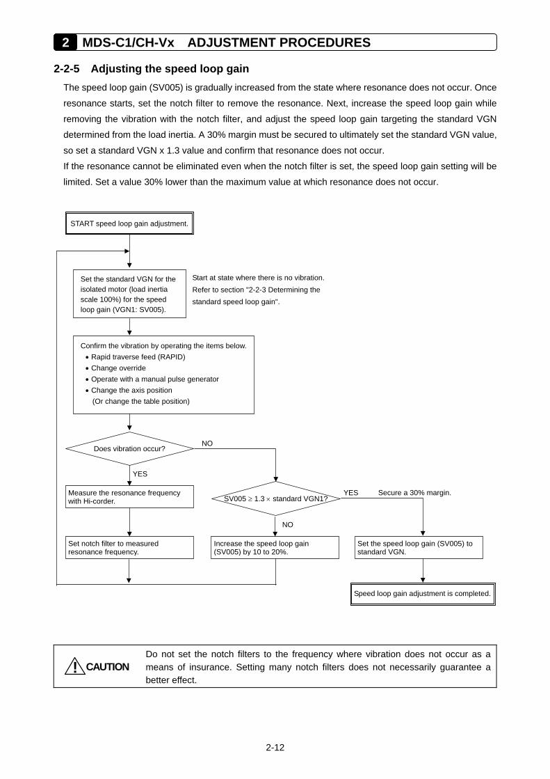
2-2-5 Adjusting the speed loop gain The speed loop gain (SV005) is gradually increased from the state where resonance does not occur. Once
resonance starts, set the notch filter to remove the resonance. Next, increase the speed loop gain while
removing the vibration with the notch filter, and adjust the speed loop gain targeting the standard VGN
determined from the load inertia. A 30% margin must be secured to ultimately set the standard VGN value,
so set a standard VGN x 1.3 value and confirm that resonance does not occur.
If the resonance cannot be eliminated even when the notch filter is set, the speed loop gain setting will be
limited. Set a value 30% lower than the maximum value at which resonance does not occur.
CAUTION!
Do not set the notch filters to the frequency where vibration does not occur as a means of insurance. Setting many notch filters does not necessarily guarantee a better effect.
Speed loop gain adjustment is completed.
START speed loop gain adjustment.
Confirm the vibration by operating the items below.• Rapid traverse feed (RAPID) • Change override • Operate with a manual pulse generator • Change the axis position
(Or change the table position)
Secure a 30% margin.
NO Does vibration occur?
YES
Set the standard VGN for the isolated motor (load inertia scale 100%) for the speed loop gain (VGN1: SV005).
Start at state where there is no vibration. Refer to section "2-2-3 Determining the standard speed loop gain".
Measure the resonance frequency with Hi-corder. SV005 ≥ 1.3 × standard VGN1?
Set notch filter to measured resonance frequency.
Increase the speed loop gain (SV005) by 10 to 20%.
Set the speed loop gain (SV005) to standard VGN.
NO
YES
2-13
POINT
1. The final SV005 (VGN1) setting value is 70% of the maximum value at which machine resonance does not occur. If the resonance is suppressed and the SV005 setting is increased by using a vibration suppression function, such as a notch filter, the servo can be adjusted easier later on.
2. If the vibration is caused by resonance (mutual action of servo control and machine characteristics), the vibration can always be stopped by lowering SV005 (VGN1). If the vibration does not change even when SV005 is lowered, there may be a problem in the machine. The notch filter is not effective when there is a problem in the machine.
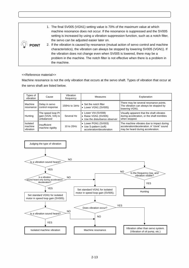
<<Reference material>>
Machine resonance is not the only vibration that occurs at the servo shaft. Types of vibration that occur at
the servo shaft are listed below.
Types of vibration Cause Vibration
frequency Measures Explanation
Machine resonance
Delay in servo control response 150Hz to 1kHz • Set the notch filter
• Lower VGN1 (SV005)
There may be several resonance points. The vibration can always be stopped by lowering VGN1.
Hunting The speed loop PI gain (VGN, VIA) is unbalanced
Several Hz • Lower VIA (SV008) • Raise VGN1 (SV005) • Use the disturbance observer
Visually apparent that the shaft vibrates during acceleration, or the shaft trembles when stopped.
Isolated machine vibration
Insufficient machine rigidity 10 to 20Hz
• Lower PGN1 (SV003) • Use S-pattern (soft)
acceleration/deceleration
The machine vibrates due to impact during acceleration/deceleration. A "clonk" sound may be heard during acceleration.
Is a vibration sound heard?
Isolated machine vibration
NO
Judging the type of vibration
Is the frequency low, and vibration visible?
Set standard VGN1 for isolated motor in speed loop gain (SV005).
Is a vibration sound heard only during acceleration/
deceleration?
YES
YES
NO Is a vibration sound heard?
Machine resonance
YES
NO
YES
Vibration other than servo system.(Vibration of oil pump, etc.)
NO
Does vibration occur?
NO
Hunting
YES
Set standard VGN1 for isolated motor in speed loop gain (SV005).
2 MDS-C1/CH-Vx ADJUSTMENT PROCEDURES
2-14
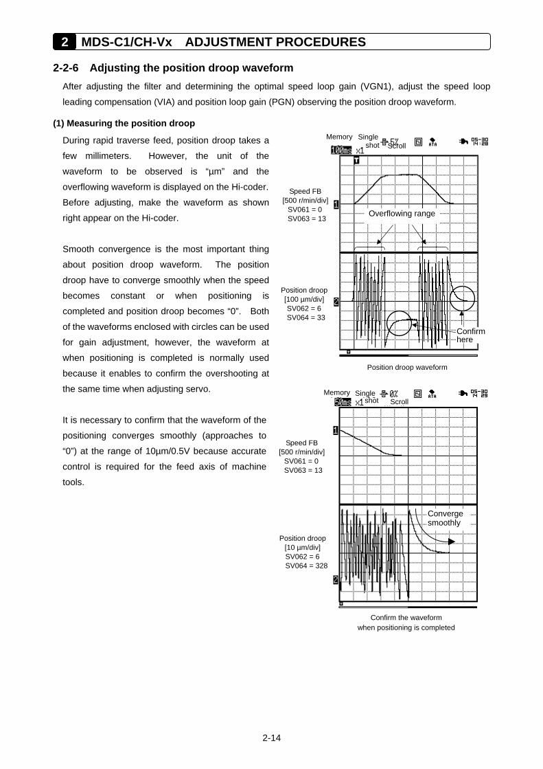
2-2-6 Adjusting the position droop waveform After adjusting the filter and determining the optimal speed loop gain (VGN1), adjust the speed loop
leading compensation (VIA) and position loop gain (PGN) observing the position droop waveform.
(1) Measuring the position droop
During rapid traverse feed, position droop takes a
few millimeters. However, the unit of the
waveform to be observed is “µm” and the
overflowing waveform is displayed on the Hi-coder.
Before adjusting, make the waveform as shown
right appear on the Hi-coder.
Smooth convergence is the most important thing
about position droop waveform. The position
droop have to converge smoothly when the speed
becomes constant or when positioning is
completed and position droop becomes “0”. Both
of the waveforms enclosed with circles can be used
for gain adjustment, however, the waveform at
when positioning is completed is normally used
because it enables to confirm the overshooting at
the same time when adjusting servo.
It is necessary to confirm that the waveform of the
positioning converges smoothly (approaches to
“0”) at the range of 10µm/0.5V because accurate
control is required for the feed axis of machine
tools.
Memory Singleshot Scroll
Position droop waveform
Position droop[100 µm/div]SV062 = 6 SV064 = 33
Speed FB [500 r/min/div]
SV061 = 0 SV063 = 13 Overflowing range
Confirmhere
Memory Singleshot Scroll
Confirm the waveform when positioning is completed
Position droop[10 µm/div] SV062 = 6 SV064 = 328
Speed FB [500 r/min/div]
SV061 = 0 SV063 = 13
Convergesmoothly
2-15
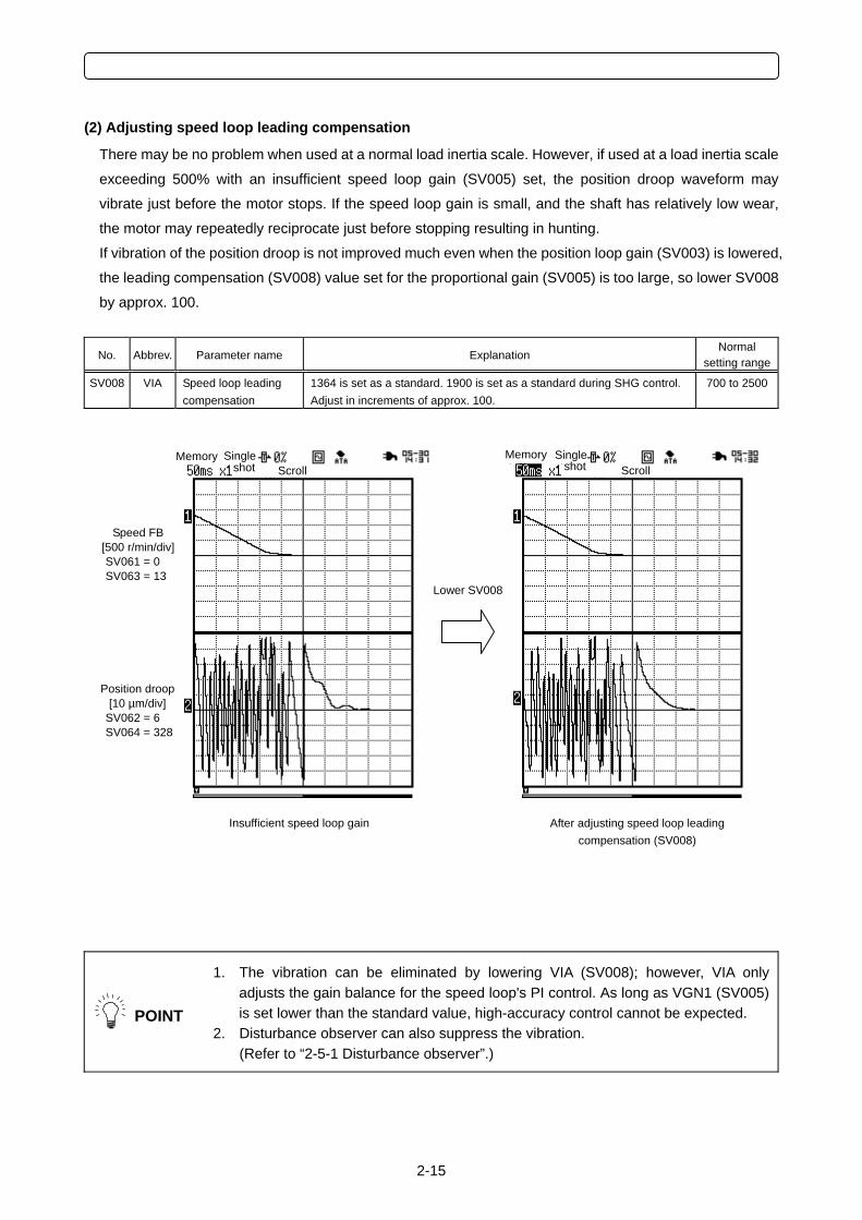
(2) Adjusting speed loop leading compensation
There may be no problem when used at a normal load inertia scale. However, if used at a load inertia scale
exceeding 500% with an insufficient speed loop gain (SV005) set, the position droop waveform may
vibrate just before the motor stops. If the speed loop gain is small, and the shaft has relatively low wear,
the motor may repeatedly reciprocate just before stopping resulting in hunting.
If vibration of the position droop is not improved much even when the position loop gain (SV003) is lowered,
the leading compensation (SV008) value set for the proportional gain (SV005) is too large, so lower SV008
by approx. 100.
No. Abbrev. Parameter name Explanation Normal
setting range
SV008 VIA Speed loop leading compensation
1364 is set as a standard. 1900 is set as a standard during SHG control. Adjust in increments of approx. 100.
700 to 2500
POINT
1. The vibration can be eliminated by lowering VIA (SV008); however, VIA only adjusts the gain balance for the speed loop's PI control. As long as VGN1 (SV005) is set lower than the standard value, high-accuracy control cannot be expected.
2. Disturbance observer can also suppress the vibration. (Refer to “2-5-1 Disturbance observer”.)
After adjusting speed loop leading compensation (SV008)
Insufficient speed loop gain
Memory Single shot Scroll Memory Single shot Scroll
Position droop [10 µm/div]
SV062 = 6 SV064 = 328
Speed FB [500 r/min/div] SV061 = 0 SV063 = 13
Lower SV008
2 MDS-C1/CH-Vx ADJUSTMENT PROCEDURES
2-16
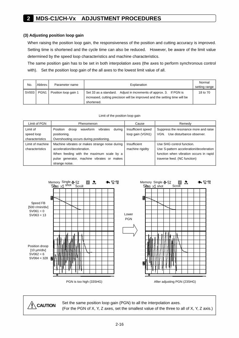
(3) Adjusting position loop gain
When raising the position loop gain, the responsiveness of the position and cutting accuracy is improved.
Setting time is shortened and the cycle time can also be reduced. However, be aware of the limit value
determined by the speed loop characteristics and machine characteristics.
The same position gain has to be set in both interpolation axes (the axes to perform synchronous control
with). Set the position loop gain of the all axes to the lowest limit value of all.
No. Abbrev. Parameter name Explanation Normal
setting range
SV003 PGN1 Position loop gain 1 Set 33 as a standard. Adjust in increments of approx. 3. If PGN is increased, cutting precision will be improved and the setting time will be shortened.
18 to 70
Limit of the position loop gain
Limit of PGN Phenomenon Cause Remedy
Limit of speed loop characteristics
Position droop waveform vibrates during positioning. Overshooting occurs during positioning.
Insufficient speed loop gain (VGN1)
Suppress the resonance more and raise VGN. Use disturbance observer.
Limit of machine characteristics
Machine vibrates or makes strange noise during acceleration/deceleration. When feeding with the maximum scale by a pulse generator, machine vibrates or makes strange noise.
Insufficient machine rigidity
Use SHG control function. Use S-pattern acceleration/deceleration function when vibration occurs in rapid traverse feed. (NC function)
CAUTION! Set the same position loop gain (PGN) to all the interpolation axes. (For the PGN of X, Y, Z axes, set the smallest value of the three to all of X, Y, Z axis.)
After adjusting PGN (23SHG) PGN is too high (33SHG)
Lower PGN
Memory Single shot Scroll Memory Single
shot Scroll
Speed FB [500 r/min/div] SV061 = 0 SV063 = 13
Position droop [10 µm/div]
SV062 = 6 SV064 = 328
2-17
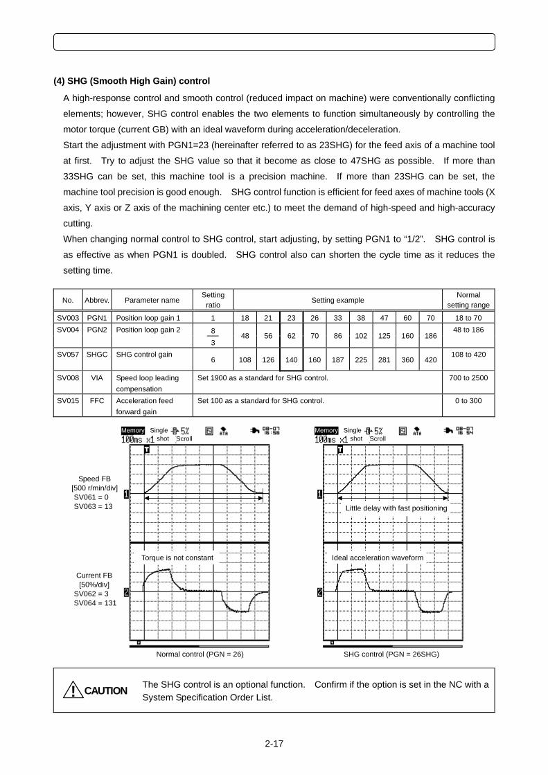
(4) SHG (Smooth High Gain) control
A high-response control and smooth control (reduced impact on machine) were conventionally conflicting
elements; however, SHG control enables the two elements to function simultaneously by controlling the
motor torque (current GB) with an ideal waveform during acceleration/deceleration.
Start the adjustment with PGN1=23 (hereinafter referred to as 23SHG) for the feed axis of a machine tool
at first. Try to adjust the SHG value so that it become as close to 47SHG as possible. If more than
33SHG can be set, this machine tool is a precision machine. If more than 23SHG can be set, the
machine tool precision is good enough. SHG control function is efficient for feed axes of machine tools (X
axis, Y axis or Z axis of the machining center etc.) to meet the demand of high-speed and high-accuracy
cutting.
When changing normal control to SHG control, start adjusting, by setting PGN1 to “1/2”. SHG control is
as effective as when PGN1 is doubled. SHG control also can shorten the cycle time as it reduces the
setting time.
No. Abbrev. Parameter name Setting
ratio Setting example Normal
setting range
SV003 PGN1 Position loop gain 1 1 18 21 23 26 33 38 47 60 70 18 to 70
8 SV004 PGN2 Position loop gain 2
3
48 56 62 70 86 102 125 160 186
48 to 186
SV057 SHGC SHG control gain
6 108 126 140 160 187 225 281 360 420 108 to 420
SV008
VIA Speed loop leading compensation
Set 1900 as a standard for SHG control.
700 to 2500
SV015
FFC Acceleration feed forward gain
Set 100 as a standard for SHG control. 0 to 300
CAUTION! The SHG control is an optional function. Confirm if the option is set in the NC with a System Specification Order List.
SHG control (PGN = 26SHG) Normal control (PGN = 26)
Ideal acceleration waveform Torque is not constant
Little delay with fast positioning
Speed FB [500 r/min/div] SV061 = 0 SV063 = 13
Current FB [50%/div]
SV062 = 3 SV064 = 131
Memory Singleshot Scroll
Memory Singleshot Scroll
2 MDS-C1/CH-Vx ADJUSTMENT PROCEDURES
2-18
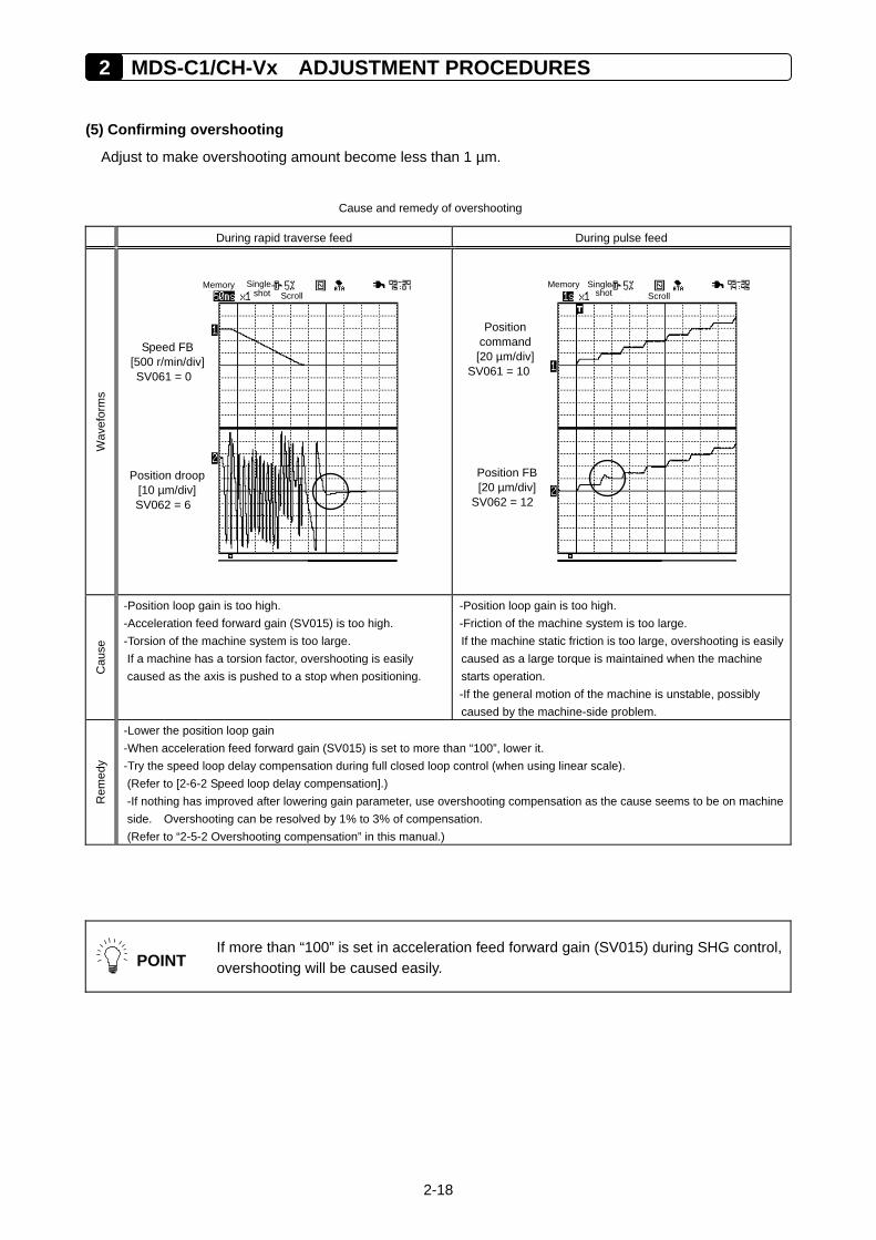
(5) Confirming overshooting
Adjust to make overshooting amount become less than 1 µm.
Cause and remedy of overshooting
During rapid traverse feed During pulse feed
Wav
efor
ms
Cau
se
-Position loop gain is too high. -Acceleration feed forward gain (SV015) is too high. -Torsion of the machine system is too large. If a machine has a torsion factor, overshooting is easily caused as the axis is pushed to a stop when positioning.
-Position loop gain is too high. -Friction of the machine system is too large. If the machine static friction is too large, overshooting is easily caused as a large torque is maintained when the machine starts operation. -If the general motion of the machine is unstable, possibly caused by the machine-side problem.
Rem
edy
-Lower the position loop gain -When acceleration feed forward gain (SV015) is set to more than “100”, lower it. -Try the speed loop delay compensation during full closed loop control (when using linear scale). (Refer to [2-6-2 Speed loop delay compensation].) -If nothing has improved after lowering gain parameter, use overshooting compensation as the cause seems to be on machine side. Overshooting can be resolved by 1% to 3% of compensation. (Refer to “2-5-2 Overshooting compensation” in this manual.)
POINT
If more than “100” is set in acceleration feed forward gain (SV015) during SHG control, overshooting will be caused easily.
Memory Single
shot Scroll
Position droop [10 µm/div] SV062 = 6
Speed FB [500 r/min/div] SV061 = 0
Memory Single
shot Scroll
Position FB [20 µm/div]
SV062 = 12
Position command [20 µm/div]
SV061 = 10
2-19
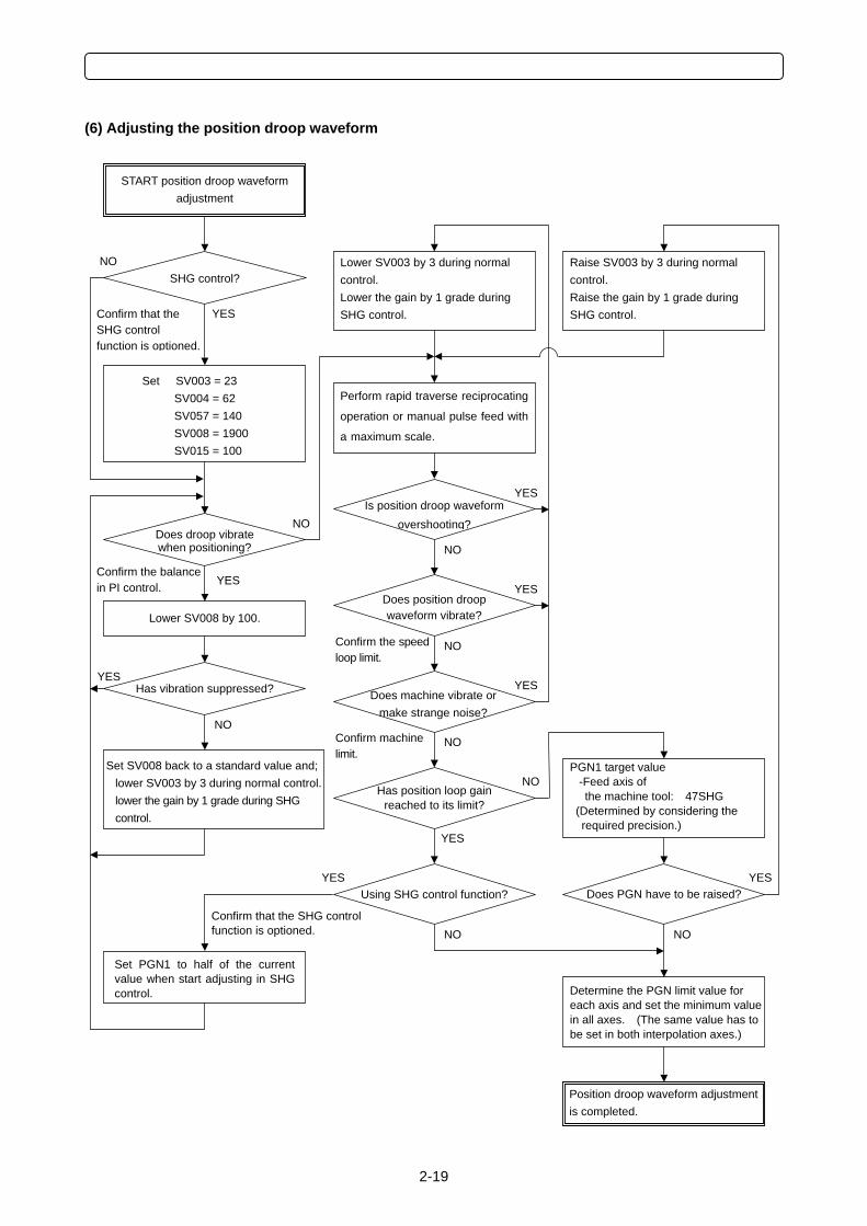
(6) Adjusting the position droop waveform
Confirm that the SHG control function is optioned.
Position droop waveform adjustment is completed.
Lower SV008 by 100.
Set SV003 = 23 SV004 = 62 SV057 = 140 SV008 = 1900 SV015 = 100
Does position droop waveform vibrate?
Has vibration suppressed?
Is position droop waveform overshooting?
Lower SV003 by 3 during normal control. Lower the gain by 1 grade during SHG control.
Using SHG control function? Does PGN have to be raised?
Does machine vibrate or make strange noise?
Has position loop gain reached to its limit?
Perform rapid traverse reciprocating
operation or manual pulse feed with
a maximum scale.
PGN1 target value -Feed axis of the machine tool: 47SHG
(Determined by considering the required precision.)
Raise SV003 by 3 during normal control. Raise the gain by 1 grade during SHG control.
Determine the PGN limit value for each axis and set the minimum value in all axes. (The same value has to be set in both interpolation axes.)
SHG control?
START position droop waveform adjustment
Does droop vibrate when positioning?
YES
NO
YES
NO
Confirm the balance in PI control.
YES
NO
Set SV008 back to a standard value and; lower SV003 by 3 during normal control.lower the gain by 1 grade during SHG control.
YES
NO
NO
YES
Confirm the speed loop limit.
YES
NOConfirm machine limit.
YES
NO
Confirm that the SHG control function is optioned.
Set PGN1 to half of the currentvalue when start adjusting in SHGcontrol.
YES YES
NO NO
2 MDS-C1/CH-Vx ADJUSTMENT PROCEDURES
2-20
2-3 Adjusting Acceleration/Deceleration Time Constant
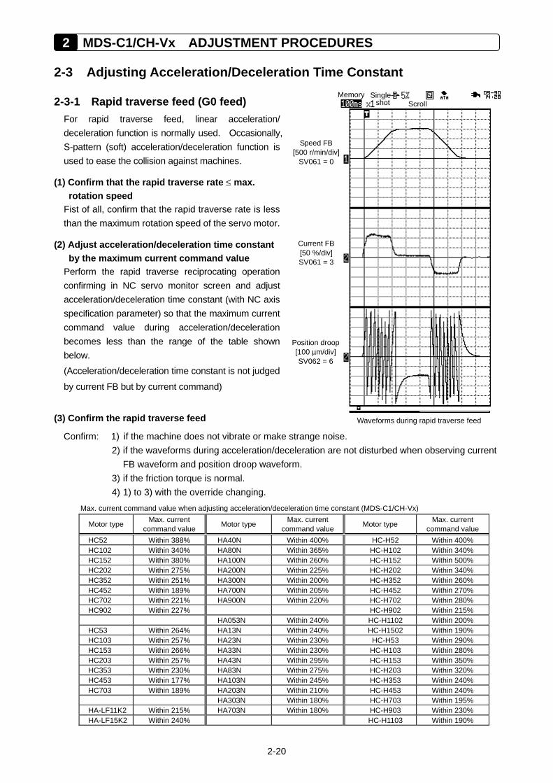
2-3-1 Rapid traverse feed (G0 feed) For rapid traverse feed, linear acceleration/ deceleration function is normally used. Occasionally, S-pattern (soft) acceleration/deceleration function is used to ease the collision against machines.
(1) Confirm that the rapid traverse rate ≤ max. rotation speed
Fist of all, confirm that the rapid traverse rate is less than the maximum rotation speed of the servo motor.
(2) Adjust acceleration/deceleration time constant by the maximum current command value
Perform the rapid traverse reciprocating operation confirming in NC servo monitor screen and adjust acceleration/deceleration time constant (with NC axis specification parameter) so that the maximum current command value during acceleration/deceleration becomes less than the range of the table shown below. (Acceleration/deceleration time constant is not judged
by current FB but by current command)
(3) Confirm the rapid traverse feed
Confirm: 1) if the machine does not vibrate or make strange noise. 2) if the waveforms during acceleration/deceleration are not disturbed when observing current
FB waveform and position droop waveform. 3) if the friction torque is normal. 4) 1) to 3) with the override changing.
Max. current command value when adjusting acceleration/deceleration time constant (MDS-C1/CH-Vx)
Motor type Max. current command value Motor type Max. current
command value Motor type Max. current command value
HC52 Within 388% HA40N Within 400% HC-H52 Within 400% HC102 Within 340% HA80N Within 365% HC-H102 Within 340% HC152 Within 380% HA100N Within 260% HC-H152 Within 500% HC202 Within 275% HA200N Within 225% HC-H202 Within 340% HC352 Within 251% HA300N Within 200% HC-H352 Within 260% HC452 Within 189% HA700N Within 205% HC-H452 Within 270% HC702 Within 221% HA900N Within 220% HC-H702 Within 280% HC902 Within 227% HC-H902 Within 215% HA053N Within 240% HC-H1102 Within 200% HC53 Within 264% HA13N Within 240% HC-H1502 Within 190% HC103 Within 257% HA23N Within 230% HC-H53 Within 290% HC153 Within 266% HA33N Within 230% HC-H103 Within 280% HC203 Within 257% HA43N Within 295% HC-H153 Within 350% HC353 Within 230% HA83N Within 275% HC-H203 Within 320% HC453 Within 177% HA103N Within 245% HC-H353 Within 240% HC703 Within 189% HA203N Within 210% HC-H453 Within 240% HA303N Within 180% HC-H703 Within 195% HA-LF11K2 Within 215% HA703N Within 180% HC-H903 Within 230% HA-LF15K2 Within 240% HC-H1103 Within 190%
Memory Single shot Scroll
Position droop[100 µm/div]SV062 = 6
Speed FB [500 r/min/div]
SV061 = 0
Current FB [50 %/div] SV061 = 3
Waveforms during rapid traverse feed
2-21
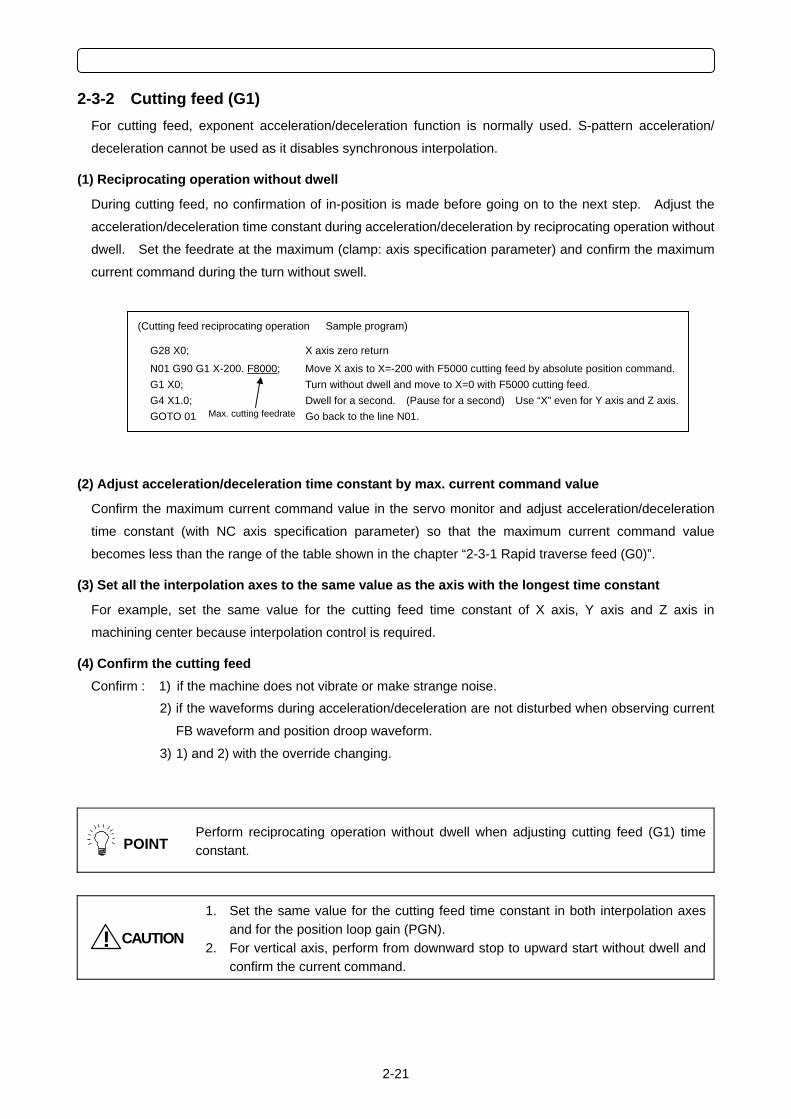
2-3-2 Cutting feed (G1) For cutting feed, exponent acceleration/deceleration function is normally used. S-pattern acceleration/
deceleration cannot be used as it disables synchronous interpolation.
(1) Reciprocating operation without dwell
During cutting feed, no confirmation of in-position is made before going on to the next step. Adjust the
acceleration/deceleration time constant during acceleration/deceleration by reciprocating operation without
dwell. Set the feedrate at the maximum (clamp: axis specification parameter) and confirm the maximum
current command during the turn without swell.
(2) Adjust acceleration/deceleration time constant by max. current command value
Confirm the maximum current command value in the servo monitor and adjust acceleration/deceleration
time constant (with NC axis specification parameter) so that the maximum current command value
becomes less than the range of the table shown in the chapter “2-3-1 Rapid traverse feed (G0)”.
(3) Set all the interpolation axes to the same value as the axis with the longest time constant
For example, set the same value for the cutting feed time constant of X axis, Y axis and Z axis in
machining center because interpolation control is required.
(4) Confirm the cutting feed Confirm : 1) if the machine does not vibrate or make strange noise.
2) if the waveforms during acceleration/deceleration are not disturbed when observing current
FB waveform and position droop waveform.
3) 1) and 2) with the override changing.
POINT
Perform reciprocating operation without dwell when adjusting cutting feed (G1) time constant.
CAUTION!
1. Set the same value for the cutting feed time constant in both interpolation axes and for the position loop gain (PGN).
2. For vertical axis, perform from downward stop to upward start without dwell and confirm the current command.
(Cutting feed reciprocating operation Sample program)
G28 X0; X axis zero return
N01 G90 G1 X-200. F8000; Move X axis to X=-200 with F5000 cutting feed by absolute position command.G1 X0; Turn without dwell and move to X=0 with F5000 cutting feed. G4 X1.0; Dwell for a second. (Pause for a second) Use “X” even for Y axis and Z axis. GOTO 01 Go back to the line N01. Max. cutting feedrate
2 MDS-C1/CH-Vx ADJUSTMENT PROCEDURES
2-22
2-4 Initial Adjustment for the Servo Functions
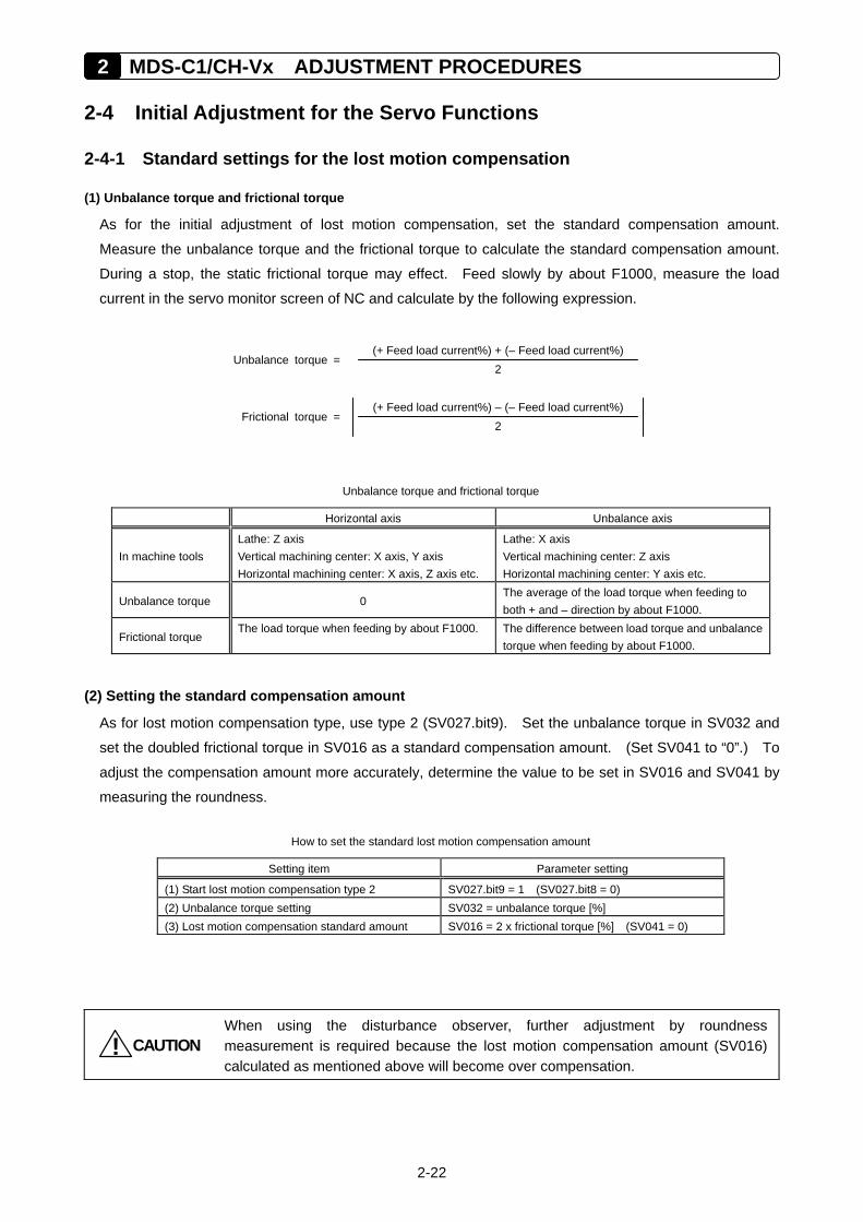
2-4-1 Standard settings for the lost motion compensation
(1) Unbalance torque and frictional torque
As for the initial adjustment of lost motion compensation, set the standard compensation amount.
Measure the unbalance torque and the frictional torque to calculate the standard compensation amount.
During a stop, the static frictional torque may effect. Feed slowly by about F1000, measure the load
current in the servo monitor screen of NC and calculate by the following expression.
Unbalance torque and frictional torque
Horizontal axis Unbalance axis
In machine tools Lathe: Z axis Vertical machining center: X axis, Y axis Horizontal machining center: X axis, Z axis etc.
Lathe: X axis Vertical machining center: Z axis Horizontal machining center: Y axis etc.
Unbalance torque 0 The average of the load torque when feeding to both + and – direction by about F1000.
Frictional torque The load torque when feeding by about F1000. The difference between load torque and unbalance
torque when feeding by about F1000.
(2) Setting the standard compensation amount
As for lost motion compensation type, use type 2 (SV027.bit9). Set the unbalance torque in SV032 and
set the doubled frictional torque in SV016 as a standard compensation amount. (Set SV041 to “0”.) To
adjust the compensation amount more accurately, determine the value to be set in SV016 and SV041 by
measuring the roundness.
How to set the standard lost motion compensation amount
Setting item Parameter setting
(1) Start lost motion compensation type 2 SV027.bit9 = 1 (SV027.bit8 = 0) (2) Unbalance torque setting SV032 = unbalance torque [%] (3) Lost motion compensation standard amount SV016 = 2 x frictional torque [%] (SV041 = 0)
CAUTION!
When using the disturbance observer, further adjustment by roundness measurement is required because the lost motion compensation amount (SV016) calculated as mentioned above will become over compensation.
2(+ Feed load current%) + (– Feed load current%)
Unbalance torque =
2(+ Feed load current%) – (– Feed load current%)
Frictional torque =
2-23
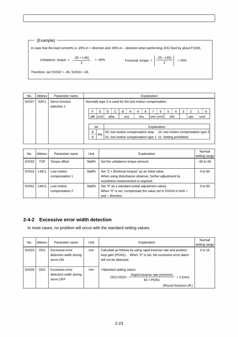
(Example)
In case that the load current% is -25% in + direction and -65% in – direction when performing JOG feed by about F1000, Therefore, set SV032 = -45, SV016 = 40.
No. Abbrev Parameter name Explanation
SV027 SSF1 Normally type 2 is used for the lost motion compensation.
Servo function selection 1
F E D C B A 9 8 7 6 5 4 3 2 1 0 aflt zrn2 afse ovs lmc omr zrn3 vfct upc vcnt bit Explanation 8 00: lost motion compensation stop 10: lost motion compensation type 2 9
lmc01: lost motion compensation type 1 11: Setting prohibited
No. Abbrev. Parameter name Unit Explanation Normal
setting range
SV032
TOF Torque offset Stall% Set the unbalance torque amount. -60 to 60
SV016 LMC1 Lost motion compensation 1
Stall% Set “2 × (frictional torque)” as an initial value. When using disturbance observer, further adjustment by roundness measurement is required.
0 to 60
SV041 LMC2 Lost motion compensation 2
Stall% Set “0” as a standard (initial adjustment value). When “0” is set, compensate the value set in SV016 in both + and – direction.
0 to 60
2-4-2 Excessive error width detection In most cases, no problem will occur with the standard setting values.
No. Abbrev. Parameter name Unit Explanation Normal
setting range
SV023
OD1 Excessive error detection width during servo ON
mm Calculate as follows by using rapid traverse rate and position loop gain (PGN1). When “0” is set, the excessive error alarm will not be detected. <Standard setting value>
Rapid traverse rate (mm/min) OD1=OD2=
60 × PGN1 ÷ 2 (mm)
SV026
OD2 Excessive error detection width during servo OFF
mm
(Round fractions off.)
3 to 15
-25 + (-65) 2
= -45% Unbalance torque = -25 - (-65)
2 = 20% Frictional torque =
2 MDS-C1/CH-Vx ADJUSTMENT PROCEDURES
2-24
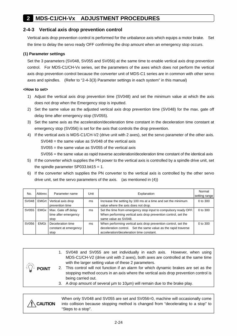
2-4-3 Vertical axis drop prevention control Vertical axis drop prevention control is performed for the unbalance axis which equips a motor brake. Set
the time to delay the servo ready OFF confirming the drop amount when an emergency stop occurs.
(1) Parameter settings
Set the 3 parameters (SV048, SV055 and SV056) at the same time to enable vertical axis drop prevention control. For MDS-C1/CH-Vx series, set the parameters of the axes which does not perform the vertical axis drop prevention control because the converter unit of MDS-C1 series are in common with other servo axes and spindles. (Refer to “2-4-3(3) Parameter settings in each system” in this manual)
<How to set>
1) Adjust the vertical axis drop prevention time (SV048) and set the minimum value at which the axis does not drop when the Emergency stop is inputted.
2) Set the same value as the adjusted vertical axis drop prevention time (SV048) for the max. gate off delay time after emergency stop (SV055).
3) Set the same axis as the acceleration/deceleration time constant in the deceleration time constant at emergency stop (SV056) is set for the axis that controls the drop prevention.
4) If the vertical axis is MDS-C1/CH-V2 (drive unit with 2 axes), set the servo parameter of the other axis. SV048 = the same value as SV048 of the vertical axis SV055 = the same value as SV055 of the vertical axis SV056 = the same value as rapid traverse acceleration/deceleration time constant of the identical axis
5) If the converter which supplies the PN power to the vertical axis is controlled by a spindle drive unit, set the spindle parameter SP033.bit15 = 1.
6) If the converter which supplies the PN converter to the vertical axis is controlled by the other servo drive unit, set the servo parameters of the axis. (as mentioned in (4))
No. Abbrev. Parameter name Unit Explanation Normal
setting rangeSV048
EMGrt Vertical axis drop
prevention time ms Increase the setting by 100 ms at a time and set the minimum
value where the axis does not drop. 0 to 300
SV055 EMGx Max. Gate off delay time after emergency stop
ms Set the time from emergency stop input to compulsory ready OFF. When performing vertical axis drop prevention control, set the same value as SV048.
0 to 300
SV056
EMGt Deceleration time constant at emergency stop
ms When performing vertical axis drop prevention control, set the deceleration control. Set the same value as the rapid traverse acceleration/deceleration time constant.
0 to 300
POINT
1. SV048 and SV055 are set individually in each axis. However, when using MDS-C1/CH-V2 (drive unit with 2 axes), both axes are controlled at the same time with the larger setting value of these 2 parameters.
2. This control will not function if an alarm for which dynamic brakes are set as the stopping method occurs in an axis where the vertical axis drop prevention control is being carried out.
3. A drop amount of several µm to 10µm) will remain due to the brake play.
CAUTION!
When only SV048 and SV055 are set and SV056=0, machine will occasionally come into collision because stopping method is changed from “decelerating to a stop” to “Steps to a stop”.
2-25
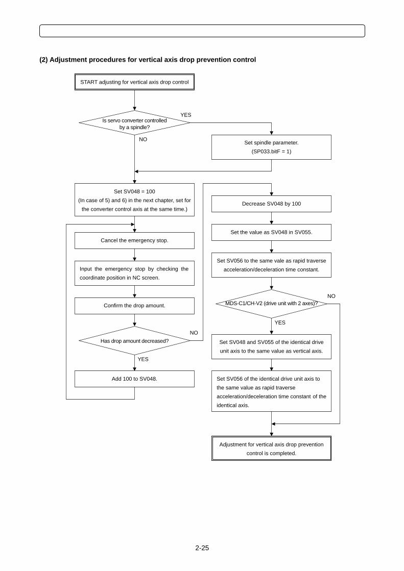
(2) Adjustment procedures for vertical axis drop prevention control
START adjusting for vertical axis drop control
Has drop amount decreased? NO
YES
Cancel the emergency stop.
Confirm the drop amount.
Add 100 to SV048.
Set the value as SV048 in SV055.
Adjustment for vertical axis drop prevention control is completed.
Set SV048 = 100 (In case of 5) and 6) in the next chapter, set for
the converter control axis at the same time.)
Is servo converter controlled by a spindle?
YES
NO Set spindle parameter. (SP033.bitF = 1)
Decrease SV048 by 100
Set SV056 to the same vale as rapid traverse acceleration/deceleration time constant.
Set SV048 and SV055 of the identical drive unit axis to the same value as vertical axis.
Set SV056 of the identical drive unit axis to the same value as rapid traverse acceleration/deceleration time constant of theidentical axis.
Input the emergency stop by checking the coordinate position in NC screen.
MDS-C1/CH-V2 (drive unit with 2 axes)? NO
YES
2 MDS-C1/CH-Vx ADJUSTMENT PROCEDURES
2-26
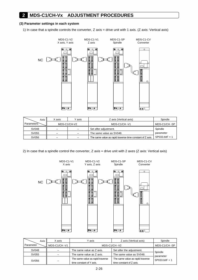
(3) Parameter settings in each system
1) In case that a spindle controls the converter, Z axis = drive unit with 1 axis. (Z axis: Vertical axis)
X axis Y axis Z axis (Vertical axis) Spindle Axis
Parameters MDS-C1/CH-V2 MDS-C1/CH -V1 MDS-C1/CH -SP
SV048 – – Set after adjustment. SV055 – – The same value as SV048. SV056 – – The same value as rapid traverse time constant of Z axis.
Spindle parameter SP033.bitF = 1
2) In case that a spindle control the converter, Z axis = drive unit with 2 axes (Z axis: Vertical axis)
X axis Y axis Z axis (Vertical axis) Spindle Axis
Parameter MDS-C1/CH -V1 MDS-C1/CH -V2 MDS-C1/CH -SP
SV048 – The same value as Z axis. Set after the adjustment. SV055 – The same value as Z axis. The same value as SV048.
SV056 – The same value as rapid traverse time constant of Y axis.
The same value as rapid traverse time constant of Z axis.
Spindle parameter SP033.bitF = 1
MDS-C1-V1 X axis
NC
MDS-C1-V2Y axis, Z axis
MDS-C1-SPSpindle
MDS-C1-CV Converter
MDS-C1-V2 X axis, Y axis
NC
MDS-C1-V1Z axis
MDS-C1-SPSpindle
MDS-C1-CV Converter
2-27
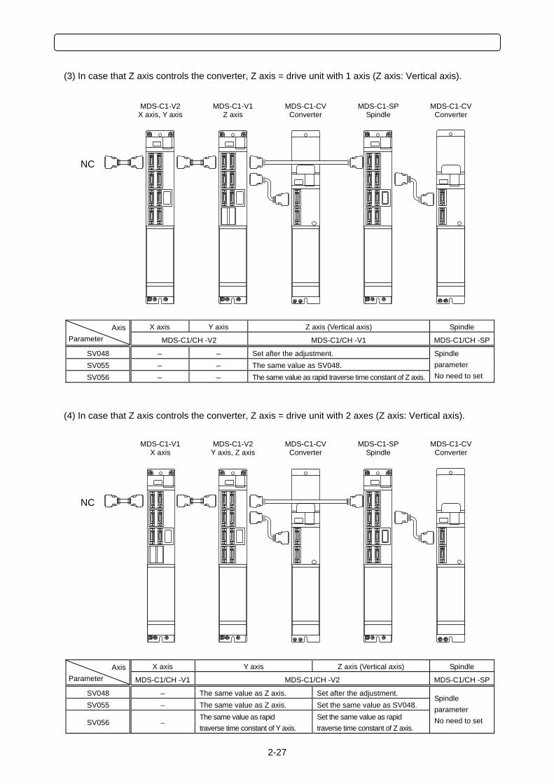
(3) In case that Z axis controls the converter, Z axis = drive unit with 1 axis (Z axis: Vertical axis).
X axis Y axis Z axis (Vertical axis) Spindle Axis
Parameter MDS-C1/CH -V2 MDS-C1/CH -V1 MDS-C1/CH -SP
SV048 – – Set after the adjustment. SV055 – – The same value as SV048. SV056 – – The same value as rapid traverse time constant of Z axis.
Spindle parameter No need to set
(4) In case that Z axis controls the converter, Z axis = drive unit with 2 axes (Z axis: Vertical axis).
X axis Y axis Z axis (Vertical axis) Spindle Axis
Parameter MDS-C1/CH -V1 MDS-C1/CH -V2 MDS-C1/CH -SP
SV048 – The same value as Z axis. Set after the adjustment. SV055 – The same value as Z axis. Set the same value as SV048.
SV056 – The same value as rapid traverse time constant of Y axis.
Set the same value as rapid traverse time constant of Z axis.
Spindle parameter No need to set
MDS-C1-V1 X axis
NC
MDS-C1-V2Y axis, Z axis
MDS-C1-SP Spindle
MDS-C1-CVConverter
MDS-C1-CVConverter
MDS-C1-V2 X axis, Y axis
NC
MDS-C1-V1Z axis
MDS-C1-SP Spindle
MDS-C1-CVConverter
MDS-C1-CVConverter
2 MDS-C1/CH-Vx ADJUSTMENT PROCEDURES
2-28
2-5 Procedures for Adjusting Each Functions
2-5-1 Disturbance observer function
(1) When to use
1) When improving cutting accuracy
Disturbance observer function is efficient to improve the cutting accuracy. For roundness
measurement, cutting accuracy can be improved especially at around 45 degrees.
2) When suppressing the vibration of position droop waveform
Disturbance observer function can suppress the vibration of position droop waveform caused by the
insufficient speed loop gain (VGN) without lowering speed loop leading compensation (VIA).
3) When suppressing the collision sound during lost motion compensation
When the lost motion compensation amount is increased, the collision sound is occasionally caused.
The compensation amount can be made smaller by using disturbance observer function, and it also
suppresses the collision sound.
(2) Precautions
1) Vibration (resonance) is easily caused
Disturbance observer is hardly used for some machine characteristics.
2) Lost motion compensation has to be readjusted
The optimum lost motion compensation amount (SV016, SV041) changes when the disturbance
observer's filter frequency (SV043) and gain (SV044) are changed.
CAUTION! When starting disturbance observer, lost motion compensation has to be adjusted again.
2-29
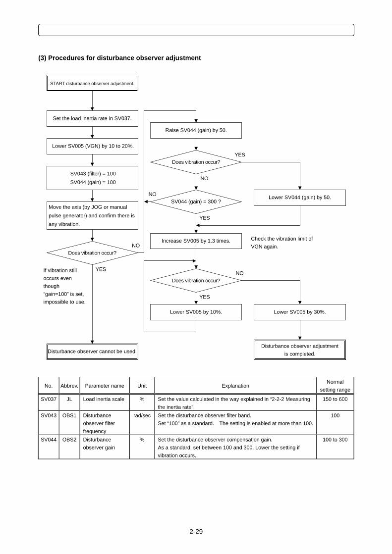
(3) Procedures for disturbance observer adjustment
No. Abbrev. Parameter name Unit Explanation Normal
setting range
SV037 JL Load inertia scale % Set the value calculated in the way explained in “2-2-2 Measuring the inertia rate”.
150 to 600
SV043 OBS1 Disturbance observer filter frequency
rad/sec Set the disturbance observer filter band. Set “100” as a standard. The setting is enabled at more than 100.
100
SV044 OBS2 Disturbance observer gain
% Set the disturbance observer compensation gain. As a standard, set between 100 and 300. Lower the setting if vibration occurs.
100 to 300
START disturbance observer adjustment.
Does vibration occur?
Lower SV005 (VGN) by 10 to 20%.
Move the axis (by JOG or manual pulse generator) and confirm there is any vibration.
SV043 (filter) = 100 SV044 (gain) = 100
Disturbance observer cannot be used.
Set the load inertia rate in SV037.
Disturbance observer adjustmentis completed.
Raise SV044 (gain) by 50.
Does vibration occur?
SV044 (gain) = 300 ? Lower SV044 (gain) by 50.
Increase SV005 by 1.3 times.
Does vibration occur?
Lower SV005 by 10%. Lower SV005 by 30%.
Check the vibration limit of VGN again.
If vibration still occurs even though “gain=100” is set, impossible to use.
YES
NO
NO
YES
NO
YES
YES
NO
2 MDS-C1/CH-Vx ADJUSTMENT PROCEDURES
2-30
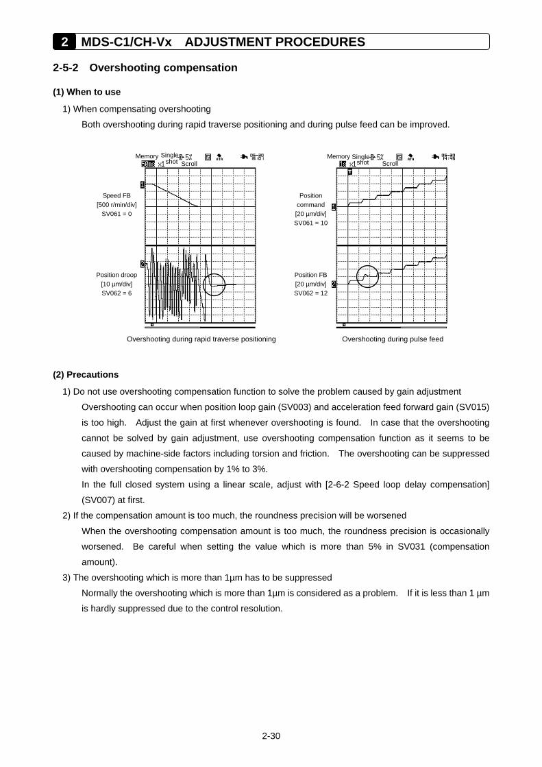
2-5-2 Overshooting compensation
(1) When to use
1) When compensating overshooting
Both overshooting during rapid traverse positioning and during pulse feed can be improved.
Overshooting during rapid traverse positioning Overshooting during pulse feed
(2) Precautions
1) Do not use overshooting compensation function to solve the problem caused by gain adjustment
Overshooting can occur when position loop gain (SV003) and acceleration feed forward gain (SV015)
is too high. Adjust the gain at first whenever overshooting is found. In case that the overshooting
cannot be solved by gain adjustment, use overshooting compensation function as it seems to be
caused by machine-side factors including torsion and friction. The overshooting can be suppressed
with overshooting compensation by 1% to 3%.
In the full closed system using a linear scale, adjust with [2-6-2 Speed loop delay compensation]
(SV007) at first.
2) If the compensation amount is too much, the roundness precision will be worsened
When the overshooting compensation amount is too much, the roundness precision is occasionally
worsened. Be careful when setting the value which is more than 5% in SV031 (compensation
amount).
3) The overshooting which is more than 1µm has to be suppressed
Normally the overshooting which is more than 1µm is considered as a problem. If it is less than 1 µm
is hardly suppressed due to the control resolution.
Memory Single shot Scroll
Position droop [10 µm/div] SV062 = 6
Speed FB [500 r/min/div]
SV061 = 0
Memory Single
shot Scroll
Position FB[20 µm/div]SV062 = 12
Position command [20 µm/div]SV061 = 10
2-31
(3) Details of overshooting compensation
1) Overshooting compensation type 1
This is an old compatible type and not used for an initial adjustment.
2) Overshooting compensation type 2
This is an old compatible type and not used for an initial adjustment.
3) Overshooting compensation type 3
This is compatible with the standard specifications. The offset amount is set based on the motor’s stall
current. Determine the amount that is free from overshoot by adjusting the compensation gain (SV031,
SV042) while increasing its value in increments of 1%. This adjustment is usually made within the
range from 1% to 3%.
During the feed forward control (the high-speed high-accuracy control), an overshoot may be
occurred due to inappropriate adjustment of the feed forward gain. So, when adjusting the
compensation gain (SV031, SV042), stop the feed forward control, or set “fwd_g” to “0”. After
adjusting, set the range of the non-sensitive zone for the overshooting compensation
“SV034(SSF3)/bit F to C” (ovsn) to “1” (2μm).
If overshoot occurs in the feed forward control mode only (no overshoot occurs in the normal control
mode), adjust the feed forward gain (fwd_g).
POINT
In the full closed system using a linear scale, adjust with [2-6-2 Speed loop delay compensation] (SV007) at first.
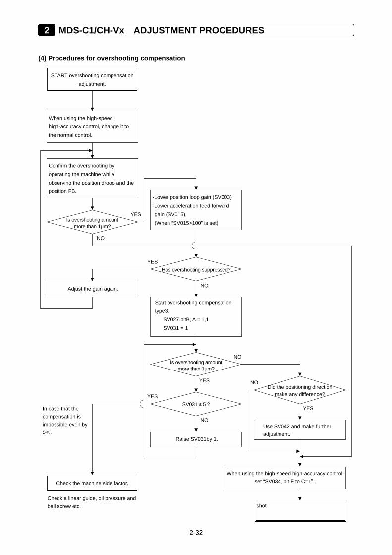
2 MDS-C1/CH-Vx ADJUSTMENT PROCEDURES
2-32
(4) Procedures for overshooting compensation
Has overshooting suppressed?
START overshooting compensation adjustment.
SV031 ≥ 5 ?
When using the high-speed high-accuracy control, change it to the normal control.
Confirm the overshooting by operating the machine while observing the position droop and the position FB.
When using the high-speed high-accuracy control, set “SV034, bit F to C=1”..
Is overshooting amount more than 1µm?
In case that the compensation is impossible even by 5%.
-Lower position loop gain (SV003) -Lower acceleration feed forward gain (SV015). (When “SV015>100” is set)
Adjust the gain again.
Start overshooting compensation type3.
SV027.bitB, A = 1,1 SV031 = 1
Is overshooting amount more than 1µm?
Raise SV031by 1.
Check the machine side factor.
Check a linear guide, oil pressure andball screw etc.
Use SV042 and make further adjustment.
Did the positioning direction make any difference?
YES
NO
NO
YES
NO
YES
YES
NO
YES
NO
shot
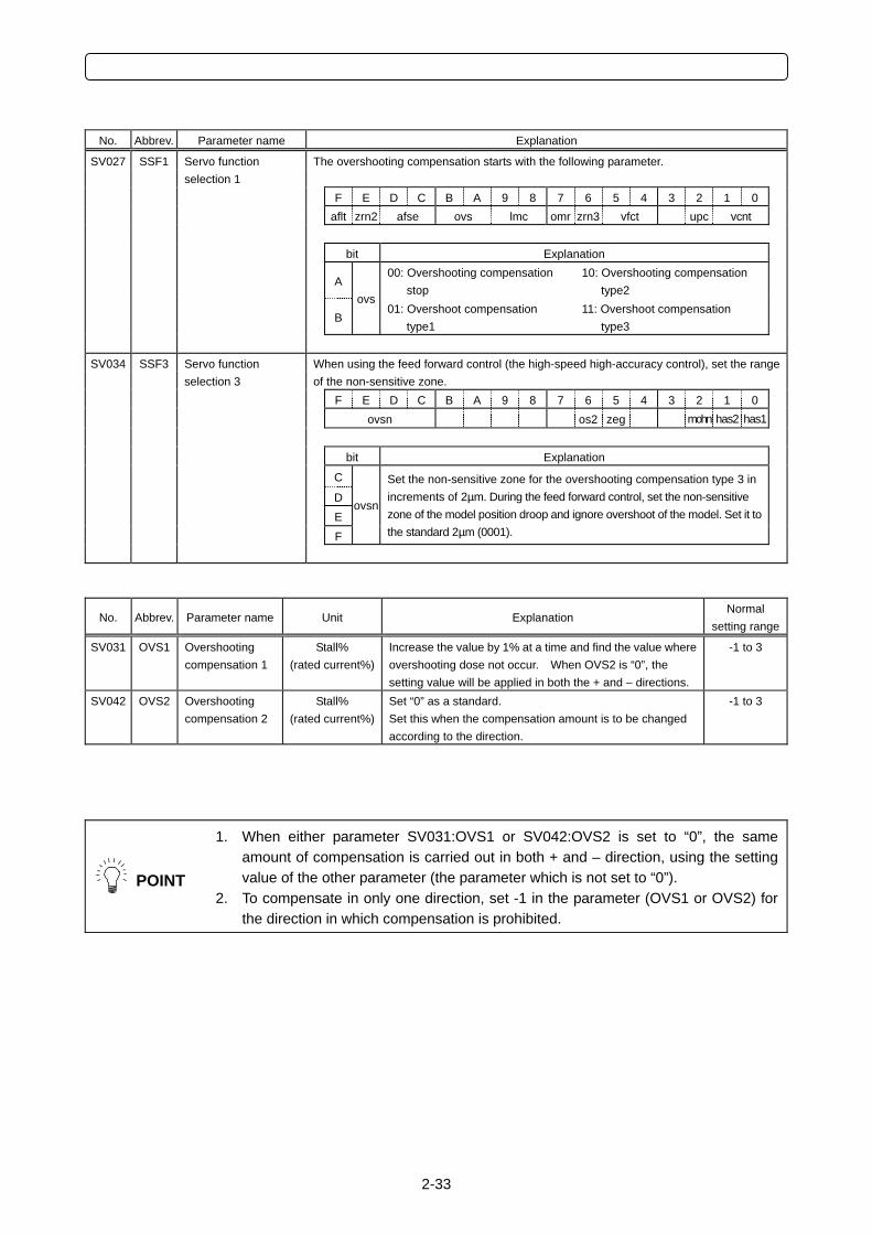
2-33
No. Abbrev. Parameter name Explanation
SV027 SSF1
The overshooting compensation starts with the following parameter.
F E D C B A 9 8 7 6 5 4 3 2 1 0 aflt zrn2 afse ovs lmc omr zrn3 vfct upc vcnt bit Explanation
A 00: Overshooting compensation
stop 10: Overshooting compensation
type2
B ovs
01: Overshoot compensation type1
11: Overshoot compensation type3
Servo function selection 1
SV034 SSF3
When using the feed forward control (the high-speed high-accuracy control), set the range of the non-sensitive zone.
F E D C B A 9 8 7 6 5 4 3 2 1 0 ovsn os2 zeg mohn has2 has1 bit Explanation
C
D E F
ovsn
Set the non-sensitive zone for the overshooting compensation type 3 in increments of 2µm. During the feed forward control, set the non-sensitive zone of the model position droop and ignore overshoot of the model. Set it to the standard 2µm (0001).
Servo function selection 3
No. Abbrev. Parameter name Unit Explanation Normal
setting range
SV031 OVS1 Overshooting compensation 1
Stall% (rated current%)
Increase the value by 1% at a time and find the value where overshooting dose not occur. When OVS2 is “0”, the setting value will be applied in both the + and – directions.
-1 to 3
SV042 OVS2 Overshooting compensation 2
Stall% (rated current%)
Set “0” as a standard. Set this when the compensation amount is to be changed according to the direction.
-1 to 3
POINT
1. When either parameter SV031:OVS1 or SV042:OVS2 is set to “0”, the same amount of compensation is carried out in both + and – direction, using the setting value of the other parameter (the parameter which is not set to “0”).
2. To compensate in only one direction, set -1 in the parameter (OVS1 or OVS2) for the direction in which compensation is prohibited.
2 MDS-C1/CH-Vx ADJUSTMENT PROCEDURES
2-34
2-5-3 Collision detection function
(1) When to use
1) To ease an impact when a machine collides
Collision detection function can ease the impact to the machine by detecting the alarm at the collision
as soon as possible when collision occurs and by causing the pullback torque.
2) To keep the alarm history separating collision alarms from over load alarms
Collision alarms are conventionally detected as over load alarms. Collision detection function
enables to keep the collision alarm history with special alarm numbers only for collision alarms.
(2) Precautions
1) Collision detection function does not guarantee the machine precision
As before, prevent the machine collision when operating a machine.
2) Alarm can be detected incorrectly
Collision is detected by detecting the disturbance torque, therefore, frictional torque or cutting torque
can be incorrectly taken for a collision depending on condition of the machine or operation.
(3) Details of collision detection method 1
The required torque is estimated by considering the position command issued by the NC. The
disturbance torque is calculated by the difference from the actual torque. When this disturbance torque
exceeds the collision detection level set by the parameters, a collision is detected.
As soon as a collision is detected, pullback torque (which is adjustable with a parameter) is commanded
and ease the impact. After the motor stopped, alarm 58 (during G0 command) or 59 (during G1
command) will occur, the system will be stopped.
Collision detection level setting parameter Detection alarm
During rapid traverse (during G0 feed) SV060 Alarm 58 During cutting feed (during G1 feed) SV060 × clG1 (SV035.bitC to E) Alarm 59
(4) Details of collision detection method 2
When the current command reaches the motor’s maximum current, collision is detected. As soon as the
collision is detected, pullback torque (which can be adjusted by a parameter) is commanded. After the
motor stopped, the alarm 5A will occur and the system will stop. If the acceleration/deceleration time
constant is short, and if detections are easily made incorrectly during normal operation, make the
acceleration/deceleration time constant longer and adjust so that the current during acceleration is not
saturated (so that the current does not reach the maximum value). Or, turn the parameter SV035.bitB ON
and ignore the collision detection method 2.
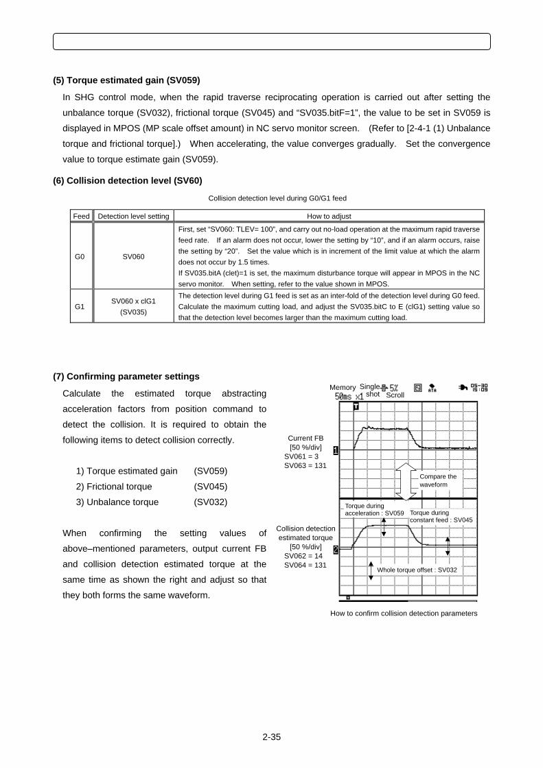
2-35
(5) Torque estimated gain (SV059)
In SHG control mode, when the rapid traverse reciprocating operation is carried out after setting the
unbalance torque (SV032), frictional torque (SV045) and “SV035.bitF=1”, the value to be set in SV059 is
displayed in MPOS (MP scale offset amount) in NC servo monitor screen. (Refer to [2-4-1 (1) Unbalance
torque and frictional torque].) When accelerating, the value converges gradually. Set the convergence
value to torque estimate gain (SV059).
(6) Collision detection level (SV60)
Collision detection level during G0/G1 feed
Feed Detection level setting How to adjust
G0 SV060
First, set “SV060: TLEV= 100”, and carry out no-load operation at the maximum rapid traverse feed rate. If an alarm does not occur, lower the setting by “10”, and if an alarm occurs, raise the setting by “20”. Set the value which is in increment of the limit value at which the alarm does not occur by 1.5 times. If SV035.bitA (clet)=1 is set, the maximum disturbance torque will appear in MPOS in the NC servo monitor. When setting, refer to the value shown in MPOS.
G1 SV060 x clG1
(SV035)
The detection level during G1 feed is set as an inter-fold of the detection level during G0 feed. Calculate the maximum cutting load, and adjust the SV035.bitC to E (clG1) setting value so that the detection level becomes larger than the maximum cutting load.
(7) Confirming parameter settings
Calculate the estimated torque abstracting
acceleration factors from position command to
detect the collision. It is required to obtain the
following items to detect collision correctly.
1) Torque estimated gain (SV059)
2) Frictional torque (SV045)
3) Unbalance torque (SV032)
When confirming the setting values of
above–mentioned parameters, output current FB
and collision detection estimated torque at the
same time as shown the right and adjust so that
they both forms the same waveform.
Memory Single shot Scroll
How to confirm collision detection parameters
Collision detection estimated torque
[50 %/div] SV062 = 14 SV064 = 131
Current FB [50 %/div]
SV061 = 3 SV063 = 131
Whole torque offset : SV032
Torque during acceleration : SV059
Compare the waveform
Torque during constant feed : SV045
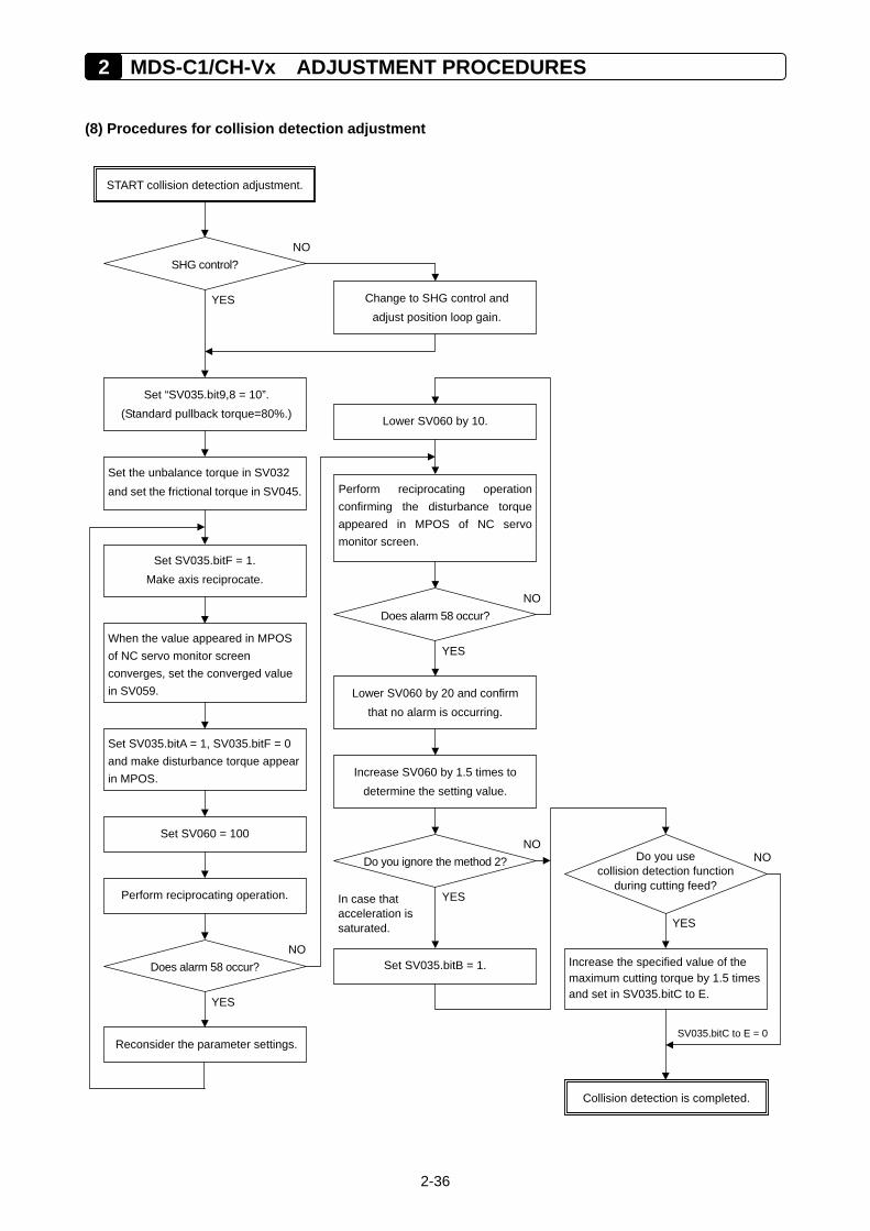
2 MDS-C1/CH-Vx ADJUSTMENT PROCEDURES
2-36
(8) Procedures for collision detection adjustment
Perform reciprocating operationconfirming the disturbance torqueappeared in MPOS of NC servomonitor screen.
In case that acceleration is saturated.
Do you use collision detection function
during cutting feed?
START collision detection adjustment.
SHG control?
YES
NO
Set the unbalance torque in SV032 and set the frictional torque in SV045.
Set SV035.bitF = 1. Make axis reciprocate.
Set SV060 = 100
When the value appeared in MPOS of NC servo monitor screen converges, set the converged value in SV059.
Set “SV035.bit9,8 = 10”. (Standard pullback torque=80%.)
Set SV035.bitA = 1, SV035.bitF = 0 and make disturbance torque appear in MPOS.
Does alarm 58 occur? NO
YES
Reconsider the parameter settings.
Perform reciprocating operation.
Change to SHG control and adjust position loop gain.
Collision detection is completed.
Lower SV060 by 10.
Does alarm 58 occur? NO
Lower SV060 by 20 and confirm that no alarm is occurring.
YES
Increase SV060 by 1.5 times to determine the setting value.
Do you ignore the method 2?
Set SV035.bitB = 1.
YES
NO
Increase the specified value of the maximum cutting torque by 1.5 times and set in SV035.bitC to E.
YES
NO
SV035.bitC to E = 0
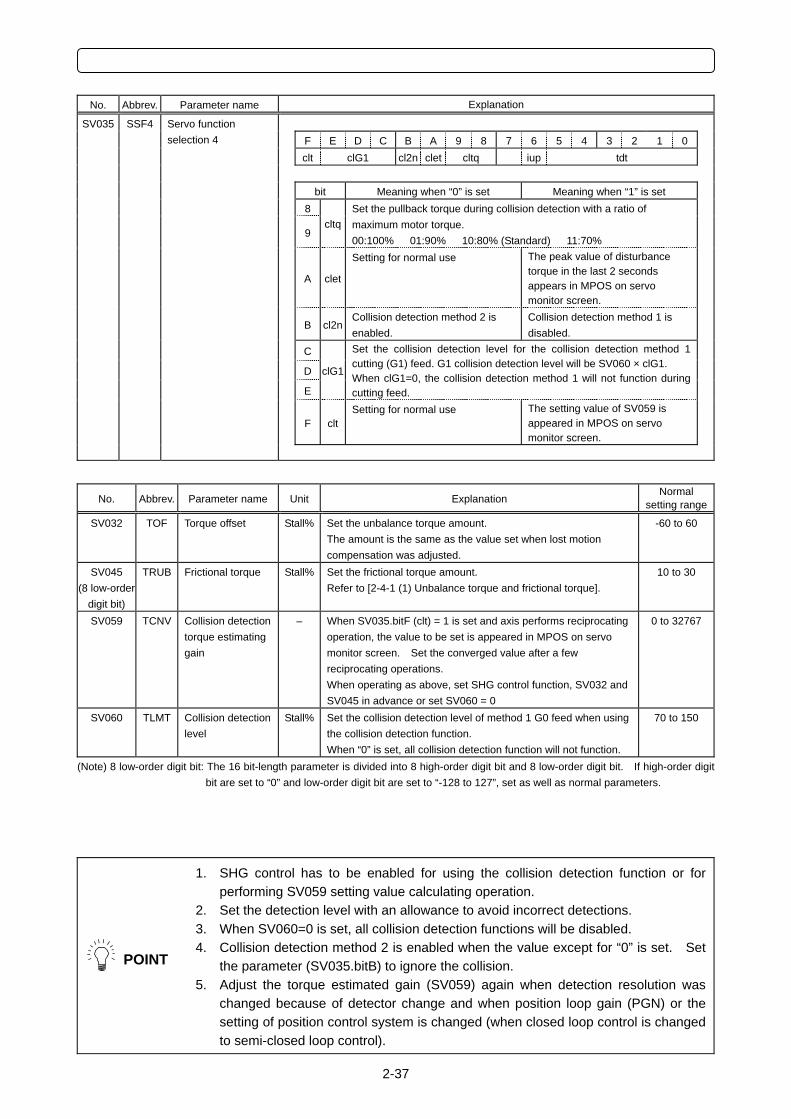
2-37
No. Abbrev. Parameter name Explanation
SV035 SSF4
Servo function selection 4 F E D C B A 9 8 7 6 5 4 3 2 1 0
clt clG1 cl2n clet cltq iup tdt bit Meaning when “0” is set Meaning when “1” is set 8
9 cltq
Set the pullback torque during collision detection with a ratio of maximum motor torque. 00:100% 01:90% 10:80% (Standard) 11:70%
A clet
Setting for normal use The peak value of disturbance torque in the last 2 seconds appears in MPOS on servo monitor screen.
B cl2nCollision detection method 2 is enabled.
Collision detection method 1 is disabled.
C
D clG1
E
Set the collision detection level for the collision detection method 1 cutting (G1) feed. G1 collision detection level will be SV060 × clG1. When clG1=0, the collision detection method 1 will not function during cutting feed.
F cltSetting for normal use The setting value of SV059 is
appeared in MPOS on servo monitor screen.
No. Abbrev. Parameter name Unit Explanation Normal
setting range
SV032 TOF Torque offset Stall% Set the unbalance torque amount. The amount is the same as the value set when lost motion compensation was adjusted.
-60 to 60
SV045 (8 low-order
digit bit)
TRUB Frictional torque Stall% Set the frictional torque amount. Refer to [2-4-1 (1) Unbalance torque and frictional torque].
10 to 30
SV059 TCNV Collision detection torque estimating gain
– When SV035.bitF (clt) = 1 is set and axis performs reciprocating operation, the value to be set is appeared in MPOS on servo monitor screen. Set the converged value after a few reciprocating operations. When operating as above, set SHG control function, SV032 and SV045 in advance or set SV060 = 0
0 to 32767
SV060 TLMT Collision detection level
Stall% Set the collision detection level of method 1 G0 feed when using the collision detection function. When “0” is set, all collision detection function will not function.
70 to 150
(Note) 8 low-order digit bit: The 16 bit-length parameter is divided into 8 high-order digit bit and 8 low-order digit bit. If high-order digit bit are set to “0” and low-order digit bit are set to “-128 to 127”, set as well as normal parameters.
POINT
1. SHG control has to be enabled for using the collision detection function or for performing SV059 setting value calculating operation.
2. Set the detection level with an allowance to avoid incorrect detections. 3. When SV060=0 is set, all collision detection functions will be disabled. 4. Collision detection method 2 is enabled when the value except for “0” is set. Set
the parameter (SV035.bitB) to ignore the collision. 5. Adjust the torque estimated gain (SV059) again when detection resolution was
changed because of detector change and when position loop gain (PGN) or the setting of position control system is changed (when closed loop control is changed to semi-closed loop control).
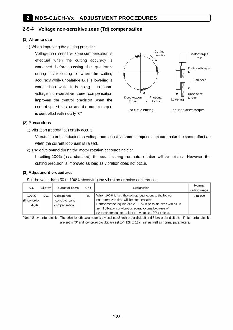
2 MDS-C1/CH-Vx ADJUSTMENT PROCEDURES
2-38
2-5-4 Voltage non-sensitive zone (Td) compensation
(1) When to use
1) When improving the cutting precision
Voltage non–sensitive zone compensation is
effectual when the cutting accuracy is
worsened before passing the quadrants
during circle cutting or when the cutting
accuracy while unbalance axis is lowering is
worse than while it is rising. In short,
voltage non–sensitive zone compensation
improves the control precision when the
control speed is slow and the output torque
is controlled with nearly “0”.
(2) Precautions
1) Vibration (resonance) easily occurs
Vibration can be inducted as voltage non–sensitive zone compensation can make the same effect as
when the current loop gain is raised.
2) The drive sound during the motor rotation becomes noisier
If setting 100% (as a standard), the sound during the motor rotation will be noisier. However, the
cutting precision is improved as long as vibration does not occur.
(3) Adjustment procedures
Set the value from 50 to 100% observing the vibration or noise occurrence.
No. Abbrev. Parameter name Unit Explanation Normal
setting range
SV030 (8 low-order digits)
IVC1 Voltage non -sensitive band compensation
% When 100% is set, the voltage equivalent to the logical non-energized time will be compensated. Compensation equivalent to 100% is possible even when 0 is set. If vibration or vibration sound occurs because of over-compensation, adjust the value to 100% or less.
0 to 100
(Note) 8 low-order digit bit: The 16bit-length parameter is divided into 8 high-order digit bit and 8 low-order digit bit. If high-order digit bit are set to “0” and low-order digit bit are set to “-128 to 127”, set as well as normal parameters.
Motor torque = 0
Frictional torque
Balanced
Unbalance torque
For unbalance torque For circle cutting
Cutting direction
Deceleration Frictional torque = torque Lowering
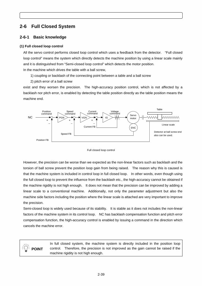
2-39
2-6 Full Closed System
2-6-1 Basic knowledge
(1) Full closed loop control
All the servo control performs closed loop control which uses a feedback from the detector. “Full closed
loop control” means the system which directly detects the machine position by using a linear scale mainly
and it is distinguished from “Semi-closed loop control” which detects the motor position.
In the machine which drives the table with a ball screw,
1) coupling or backlash of the connecting point between a table and a ball screw
2) pitch error of a ball screw
exist and they worsen the precision. The high-accuracy position control, which is not affected by a
backlash nor pitch error, is enabled by detecting the table position directly as the table position means the
machine end.
However, the precision can be worse than we expected as the non-linear factors such as backlash and the
torsion of ball screw prevent the position loop gain from being raised. The reason why this is caused is
that the machine system is included in control loop in full closed loop. In other words, even though using
the full closed loop to prevent the influence from the backlash etc., the high-accuracy cannot be obtained if
the machine rigidity is not high enough. It does not mean that the precision can be improved by adding a
linear scale to a conventional machine. Additionally, not only the parameter adjustment but also the
machine side factors including the position where the linear scale is attached are very important to improve
the precision.
Semi-closed loop is widely used because of its stability. It is stable as it does not includes the non-linear
factors of the machine system in its control loop. NC has backlash compensation function and pitch error
compensation function, the high-accuracy control is enabled by issuing a command in the direction which
cancels the machine error.
POINT
In full closed system, the machine system is directly included in the position loop control. Therefore, the precision is not improved as the gain cannot be raised if the machine rigidity is not high enough.
Linear scale
Full closed loop control
Servomotor
ENC
IG+
–
VGN+
–
PGN +
–
NC
Position
Position FB
Current FB
Speed FB
Speed Current VoltageTable
Detector at ball screw end also can be used.
command command command command
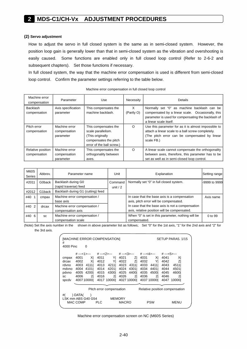
2 MDS-C1/CH-Vx ADJUSTMENT PROCEDURES
2-40
(2) Servo adjustment
How to adjust the servo in full closed system is the same as in semi-closed system. However, the
position loop gain is generally lower than that in semi-closed system as the vibration and overshooting is
easily caused. Some functions are enabled only in full closed loop control (Refer to 2-6-2 and
subsequent chapters). Set those functions if necessary.
In full closed system, the way that the machine error compensation is used is different from semi-closed
loop control. Confirm the parameter settings referring to the table below.
Machine error compensation in full closed loop control
Machine error compensation
Parameter Use Necessity Details
Backlash compensation
Axis specification parameter
This compensates the machine backlash.
X (Partly O)
Normally set “0” as machine backlash can be compensated by a linear scale. Occasionally, this parameter is used for compensating the backlash of a linear scale itself.
Pitch error compensation
Machine error compensation parameter
This compensates the scale parallelism. (This originally compensates the pitch error of the ball screw.)
O Use this parameter for as it is almost impossible to attach a linear scale to a ball screw completely. (The pitch error can be compensated by linear scale FB.)
Relative position compensation
Machine error compensation parameter
This compensates the orthogonality between axes.
O A linear scale cannot compensate the orthogonality between axes, therefore, this parameter has to be set as well as in semi-closed loop control.
M60S Series
Abbrev. Parameter name Unit Explanation Setting range
#2011 G0back Backlash during G0 (rapid traverse) feed
#2012 G1back Backlash during G1 (cutting) feed
Command unit / 2
Normally set “0” in full closed system. -9999 to 9999
#40 1 cmpax Machine error compensation / base axis
#40 2 drcax Machine error compensation / compensation axis
In case that the base axis is a compensation axis, pitch error will be compensated. In case that the base axis is not a compensation axis, relative position will be compensated.
Axis name
#40 6 sc Machine error compensation / compensation scale
When “0” is set in this parameter, nothing will be compensated.
0 to 99
(Note) Set the axis number in the shown in above parameter list as follows; Set “0” for the 1st axis, “1” for the 2nd axis and “2” for the 3rd axis.
Machine error compensation screen on NC (M60S Series)
[MACHINE ERROR COMPENSATION] SETUP PARA5. 1/15 # 4000 Pinc 0 # ---<1>--- # ---<2>--- # ---<3>--- # ---<4>--- # ---<5>--- cmpax 4001 X| 4011 Y| 4021 Z| 4031 X| 4041 X| drcax 4002 X| 4012 Y| 4022 Z| 4032 Y| 4042 Z| rdvno 4003 4111| 4013 4211| 4023 4311| 4033 4411| 4043 4511| mdvno 4004 4101| 4014 4201| 4024 4301| 4034 4401| 4044 4501| pdvno 4005 4200| 4015 4300| 4025 4400| 4035 4500| 4045 4600| sc 4006 2| 4016 2| 4026 2| 4036 2| 4046 2| spcdv 4007 10000| 4017 10000| 4027 10000| 4037 10000| 4047 10000| #( ) DATA( ) LSK mm ABS G40 G54 MEMORY MAC COMP PLC MACRO PSW MENU
Pitch error compensation
Relative position compensation
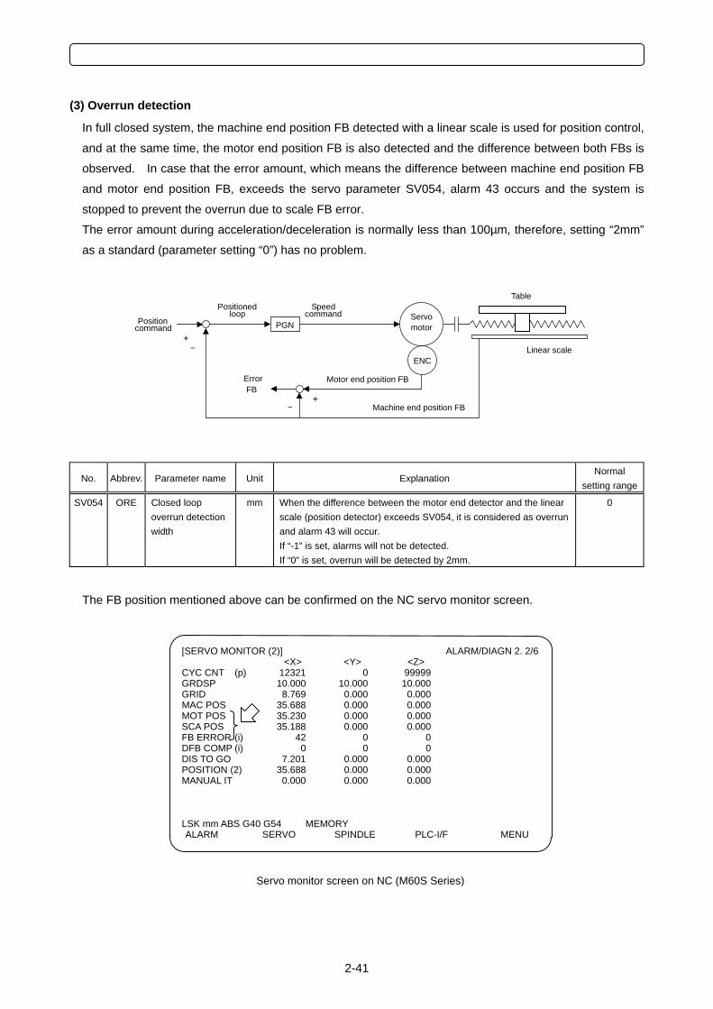
2-41
(3) Overrun detection
In full closed system, the machine end position FB detected with a linear scale is used for position control,
and at the same time, the motor end position FB is also detected and the difference between both FBs is
observed. In case that the error amount, which means the difference between machine end position FB
and motor end position FB, exceeds the servo parameter SV054, alarm 43 occurs and the system is
stopped to prevent the overrun due to scale FB error.
The error amount during acceleration/deceleration is normally less than 100µm, therefore, setting “2mm”
as a standard (parameter setting “0”) has no problem.
No. Abbrev. Parameter name Unit Explanation Normal
setting range
SV054 ORE Closed loop overrun detection width
mm When the difference between the motor end detector and the linear scale (position detector) exceeds SV054, it is considered as overrun and alarm 43 will occur. If “-1” is set, alarms will not be detected. If “0” is set, overrun will be detected by 2mm.
0
The FB position mentioned above can be confirmed on the NC servo monitor screen.
PGN +
–
FB
Servomotor
ENCLinear scale
Table
Machine end position FB
Motor end position FB
+ –
Positioned loop
Speed command
Position command
Error
[SERVO MONITOR (2)] ALARM/DIAGN 2. 2/6 <X> <Y> <Z>
CYC CNT (p) 12321 0 99999 GRDSP 10.000 10.000 10.000 GRID 8.769 0.000 0.000 MAC POS 35.688 0.000 0.000 MOT POS 35.230 0.000 0.000 SCA POS 35.188 0.000 0.000 FB ERROR (i) 42 0 0 DFB COMP (i) 0 0 0 DIS TO GO 7.201 0.000 0.000 POSITION (2) 35.688 0.000 0.000 MANUAL IT 0.000 0.000 0.000 LSK mm ABS G40 G54 MEMORY ALARM SERVO SPINDLE PLC-I/F MENU
Servo monitor screen on NC (M60S Series)
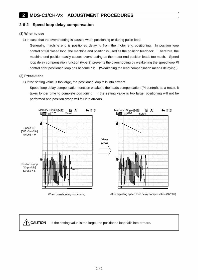
2 MDS-C1/CH-Vx ADJUSTMENT PROCEDURES
2-42
2-6-2 Speed loop delay compensation
(1) When to use
1) In case that the overshooting is caused when positioning or during pulse feed
Generally, machine end is positioned delaying from the motor end positioning. In position loop
control of full closed loop, the machine end position is used as the position feedback. Therefore, the
machine end position easily causes overshooting as the motor end position leads too much. Speed
loop delay compensation function (type 2) prevents the overshooting by weakening the speed loop PI
control after positioned loop has become “0”. (Weakening the lead compensation means delaying.)
(2) Precautions
1) If the setting value is too large, the positioned loop falls into arrears
Speed loop delay compensation function weakens the leads compensation (PI control), as a result, it
takes longer time to complete positioning. If the setting value is too large, positioning will not be
performed and position droop will fall into arrears.
CAUTION! If the setting value is too large, the positioned loop falls into arrears.
After adjusting speed loop delay compensation (SV007)When overshooting is occurring
Memory Single shot Scroll OMemory Single shot Scroll
Position droop [10 µm/div] SV062 = 6
Speed FB [500 r/min/div]
SV061 = 0 Adjust
SV007
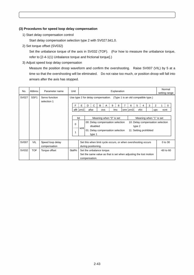
2-43
(3) Procedures for speed loop delay compensation
1) Start delay compensation control
Start delay compensation selection type 2 with SV027.bit1,0.
2) Set torque offset (SV032)
Set the unbalance torque of the axis in SV032 (TOF). (For how to measure the unbalance torque,
refer to [2-4-1(1) Unbalance torque and frictional torque].)
3) Adjust speed loop delay compensation
Measure the position droop waveform and confirm the overshooting. Raise SV007 (VIL) by 5 at a
time so that the overshooting will be eliminated. Do not raise too much, or position droop will fall into
arrears after the axis has stopped.
No. Abbrev. Parameter name Unit Explanation Normal
setting range
SV027 SSF1 Use type 2 for delay compensation. (Type 1 is an old compatible type.)
Servo function selection 1
F E D C B A 9 8 7 6 5 4 3 2 1 0 aflt zrn2 afse ovs lmc omr zrn3 vfct upc vcnt bit Meaning when “0” is set Meaning when “1” is set
0 00: Delay compensation selection
disabled 10: Delay compensation selection
type 2
1 vcnt
01: Delay compensation selection type 1
11: Setting prohibited
SV007 VIL Speed loop delay
compensation Set this when limit cycle occurs, or when overshooting occurs
during positioning. 0 to 30
SV032 TOF Torque offset Stall% Set the unbalance torque. Set the same value as that is set when adjusting the lost motion compensation.
-60 to 60
2 MDS-C1/CH-Vx ADJUSTMENT PROCEDURES
2-44
2-6-3 Dual feedback control
(1) When to use
1) When the precision of the surface cut by deep cuts function is not good
When using a linear scale, the feedback will be returned sensitively until the cutting load collides as it
directly detects the machine end position including a table etc. As a result, the position loop control
becomes unstable, and the cut surface may have undulation. Dual feedback control enables the
stable control and also the cutting precision is improved as the high frequency factors included in the
machine end FB is eliminated.
2) When position droop vibrates during acceleration/deceleration
In case that the rigidity of machine system is low in the full closed system of a larger machine etc.,
position loop gain cannot be raised occasionally as the response at acceleration/deceleration
becomes vibrative and overshooting is caused. By using dual feedback control, the vibration limit of
the position loop gain (PGN) can be raised as it enables the stable position loop control.
(2) Precautions
1) Optional functions
Dual feedback control is an optional function. In case that the initial parameter error (error No. 103,
error No. 2303 in M60S series) occurs, option parameter does not exist.
2) Do not raise the control time constant (SV051) too much
When raising the control time constant (SV051), the limit of position loop gain can be raised up to the
level of semi-closed loop control, however, it affects interpolation precision and the quadrant
protrusion cannot be compensated completely by lost motion compensation. (In case that the
machine backlash is large,) this phenomenon occurs remarkably especially in the machine whose
cutting feedrate is very fast. When raising time constant, the position loop control becomes stable as
it becomes similar to the semi-closed loop control, however, it means that the machine end (linear
scale) FB is not used.
3) Positioning time is postponed
In dual feedback control, positioning is performed according to the motor end FB position, and then
moved to the machine end FB position according to control time constant (SV051). If the control
time constant is small (less than about 20ms), it will not affect. However, if the difference between
motor end FB and machine end FB is large and the control time constant is also large, it takes longer
time to carry out the final positioning.
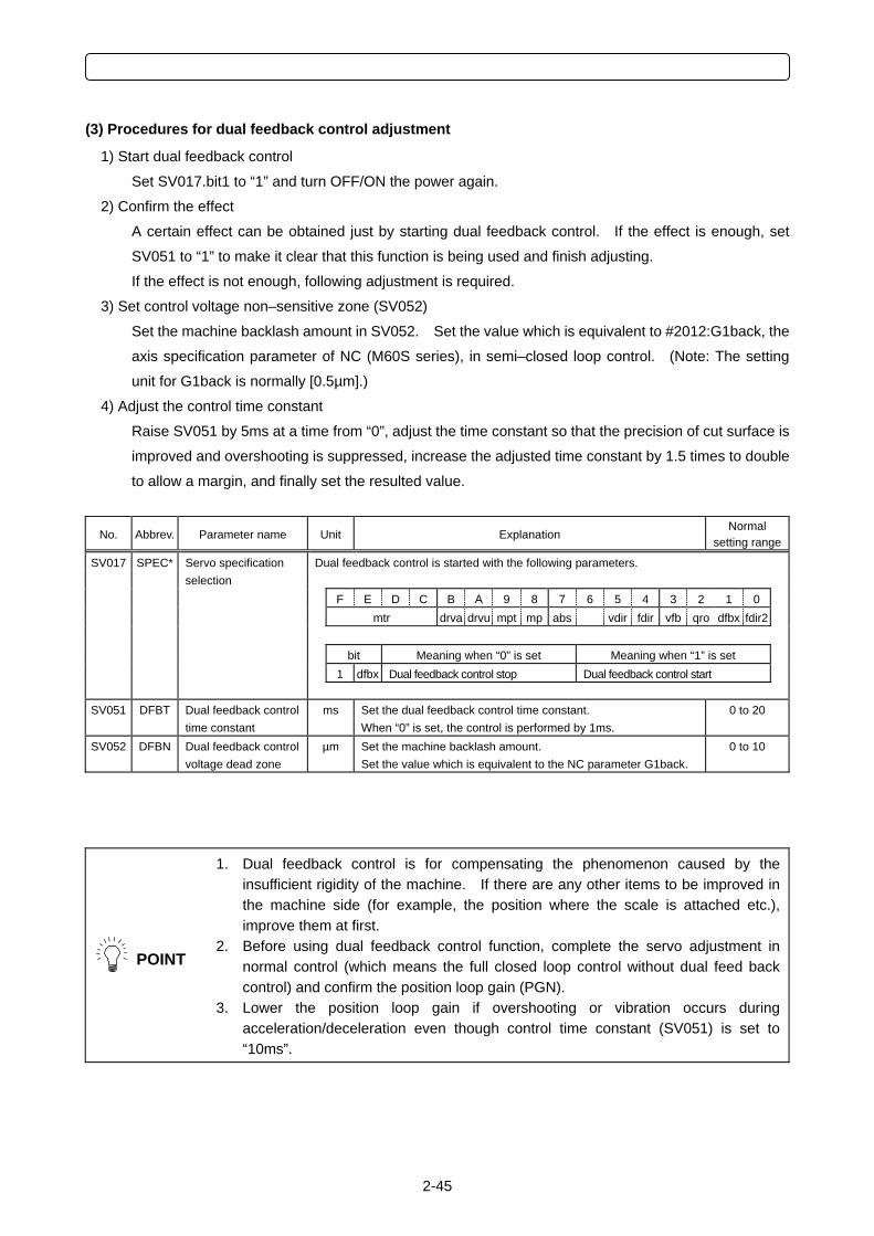
2-45
(3) Procedures for dual feedback control adjustment
1) Start dual feedback control
Set SV017.bit1 to “1” and turn OFF/ON the power again.
2) Confirm the effect
A certain effect can be obtained just by starting dual feedback control. If the effect is enough, set
SV051 to “1” to make it clear that this function is being used and finish adjusting.
If the effect is not enough, following adjustment is required.
3) Set control voltage non–sensitive zone (SV052)
Set the machine backlash amount in SV052. Set the value which is equivalent to #2012:G1back, the
axis specification parameter of NC (M60S series), in semi–closed loop control. (Note: The setting
unit for G1back is normally [0.5µm].)
4) Adjust the control time constant
Raise SV051 by 5ms at a time from “0”, adjust the time constant so that the precision of cut surface is
improved and overshooting is suppressed, increase the adjusted time constant by 1.5 times to double
to allow a margin, and finally set the resulted value.
No. Abbrev. Parameter name Unit Explanation Normal
setting range
SV017 SPEC* Dual feedback control is started with the following parameters.
Servo specification selection
F E D C B A 9 8 7 6 5 4 3 2 1 0 mtr drva drvu mpt mp abs vdir fdir vfb qro dfbx fdir2 bit Meaning when “0” is set Meaning when “1” is set 1 dfbx Dual feedback control stop Dual feedback control start
SV051 DFBT Dual feedback control time constant
ms Set the dual feedback control time constant. When “0” is set, the control is performed by 1ms.
0 to 20
SV052 DFBN Dual feedback control voltage dead zone
µm Set the machine backlash amount. Set the value which is equivalent to the NC parameter G1back.
0 to 10
POINT
1. Dual feedback control is for compensating the phenomenon caused by the insufficient rigidity of the machine. If there are any other items to be improved in the machine side (for example, the position where the scale is attached etc.), improve them at first.
2. Before using dual feedback control function, complete the servo adjustment in normal control (which means the full closed loop control without dual feed back control) and confirm the position loop gain (PGN).
3. Lower the position loop gain if overshooting or vibration occurs during acceleration/deceleration even though control time constant (SV051) is set to “10ms”.
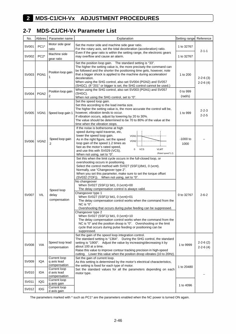
2 MDS-C1/CH-Vx ADJUSTMENT PROCEDURES
2-46
2-7 MDS-C1/CH-Vx Parameter List No. Abbrev. Parameter name Explanation Setting range Reference
SV001 PC1* Motor side gear ratio
1 to 32767
SV002 PC2* Machine side gear ratio
Set the motor side and machine side gear ratio. For the rotary axis, set the total deceleration (acceleration) ratio. Even if the gear ratio is within the setting range, the electronic gears may overflow and cause an alarm. 1 to 32767
2-1-1
SV003 PGN1 Position loop gain 1
Set the position loop gain. The standard setting is “33”. The higher the setting value is, the more precisely the command can be followed and the shorter the positioning time gets, however, note that a bigger shock is applied to the machine during acceleration/ deceleration. When using the SHG control, also set SV004 (PGN2) and SV057 (SHGC). (If “201” or bigger is set, the SHG control cannot be used.)
1 to 200
SV004 PGN2 Position loop gain 2
When using the SHG control, also set SV003 (PGN1) and SV057 (SHGC). When not using the SHG control, set to “0”.
0 to 999 (rad/s)
2-2-6 (3)2-2-6 (4)
SV005 VGN1 Speed loop gain 1
Set the speed loop gain. Set this according to the load inertia size. The higher the setting value is, the more accurate the control will be, however, vibration tends to occur. If vibration occurs, adjust by lowering by 20 to 30%. The value should be determined to be 70 to 80% of the value at the time when the vibration stops.
1 to 999 2-2-3 2-2-5
VGN1
VGN2
VCS VLMT
SV006 VGN2 Speed loop gain 2
If the noise is bothersome at high speed during rapid traverse, etc, lower the speed loop gain. As in the right figure, set the speed loop gain of the speed 1.2 times as fast as the motor’s rated speed, and use this with SV029 (VCS). When not using, set to “0”.
0(Rated speed*1.2)
-1000 to 1000
–
Set this when the limit cycle occurs in the full-closed loop, or overshooting occurs in positioning. Select the control method with SV027 (SSF1)/bit1, 0 (vcnt). Normally, use “Changeover type 2”. When you set this parameter, make sure to set the torque offset (SV032 (TOF)). When not using, set to “0”.
No changeover When SV027 (SSF1)/ bit1, 0 (vcnt)=00 The delay compensation control is always valid.
Changeover type 1 When SV027 (SSF1)/ bit1, 0 (vcnt)=01 The delay compensation control works when the command from the NC is “0”. Overshooting that occurs during pulse feeding can be suppressed.
SV007 VIL Speed loop delay compensation
Changeover type 2 When SV027 (SSF1)/ bit1, 0 (vcnt)=10 The delay compensation control works when the command from the NC is “0” and the position droop is “0”. Overshooting or the limit cycle that occurs during pulse feeding or positioning can be suppressed.
0 to 32767 2-6-2
SV008 VIA Speed loop lead compensation
Set the gain of the speed loop integration control. The standard setting is “1364”. During the SHG control, the standard setting is “1900”. Adjust the value by increasing/decreasing it by about 100 at a time. Raise this value to improve contour tracking precision in high-speed cutting. Lower this value when the position droop vibrates (10 to 20Hz).
1 to 9999 2-2-6 (2)2-2-6 (4)
SV009 IQA Current loop q axis lead compensation
SV010 IDA Current loop d axis lead compensation
1 to 20480
SV011 IQG Current loop q axis gain
SV012 IDG Current loop d axis gain
Set the gain of current loop. As this setting is determined by the motor’s electrical characteristics, the setting is fixed for each type of motor. Set the standard values for all the parameters depending on each motor type.
1 to 4096
–
The parameters marked with * such as PC1* are the parameters enabled when the NC power is turned ON again.
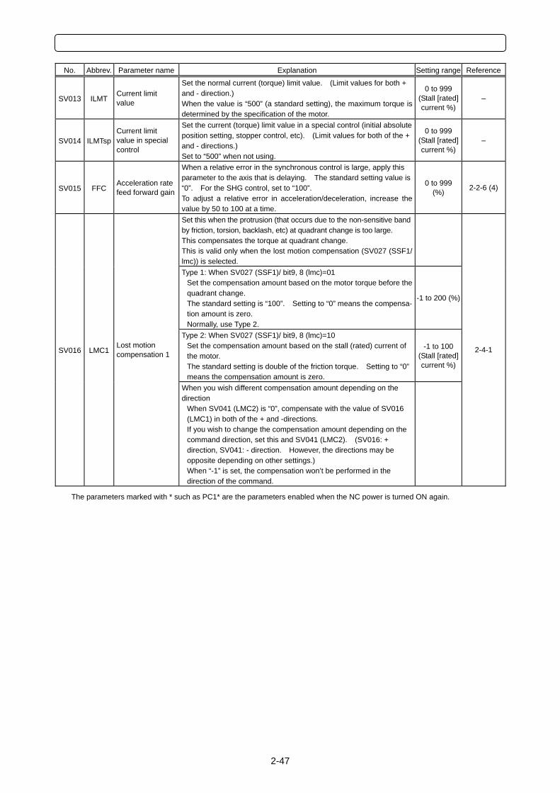
2-47
No. Abbrev. Parameter name Explanation Setting range Reference
SV013 ILMT Current limit value
Set the normal current (torque) limit value. (Limit values for both + and - direction.) When the value is “500” (a standard setting), the maximum torque is determined by the specification of the motor.
0 to 999 (Stall [rated] current %)
–
SV014 ILMTsp Current limit value in special control
Set the current (torque) limit value in a special control (initial absolute position setting, stopper control, etc). (Limit values for both of the + and - directions.) Set to “500” when not using.
0 to 999 (Stall [rated] current %)
–
SV015 FFC Acceleration rate feed forward gain
When a relative error in the synchronous control is large, apply this parameter to the axis that is delaying. The standard setting value is “0”. For the SHG control, set to “100”. To adjust a relative error in acceleration/deceleration, increase the value by 50 to 100 at a time.
0 to 999 (%) 2-2-6 (4)
Set this when the protrusion (that occurs due to the non-sensitive band by friction, torsion, backlash, etc) at quadrant change is too large. This compensates the torque at quadrant change. This is valid only when the lost motion compensation (SV027 (SSF1/ lmc)) is selected.
Type 1: When SV027 (SSF1)/ bit9, 8 (lmc)=01 Set the compensation amount based on the motor torque before the quadrant change. The standard setting is “100”. Setting to “0” means the compensa- tion amount is zero. Normally, use Type 2.
-1 to 200 (%)
Type 2: When SV027 (SSF1)/ bit9, 8 (lmc)=10 Set the compensation amount based on the stall (rated) current of the motor. The standard setting is double of the friction torque. Setting to “0” means the compensation amount is zero.
-1 to 100 (Stall [rated] current %)
SV016 LMC1 Lost motion compensation 1
When you wish different compensation amount depending on the direction
When SV041 (LMC2) is “0”, compensate with the value of SV016 (LMC1) in both of the + and -directions. If you wish to change the compensation amount depending on the command direction, set this and SV041 (LMC2). (SV016: + direction, SV041: - direction. However, the directions may be opposite depending on other settings.) When “-1” is set, the compensation won’t be performed in the direction of the command.
2-4-1
The parameters marked with * such as PC1* are the parameters enabled when the NC power is turned ON again.
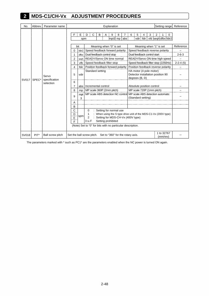
2 MDS-C1/CH-Vx ADJUSTMENT PROCEDURES
2-48
No. Abbrev. Parameter name Explanation Setting range Reference
F E D C B A 9 8 7 6 5 4 3 2 1 0 spm mpt3 mp abs vdir fdir vfd seqh dfbx fdir2
bit Meaning when “0” is set Meaning when “1” is set Reference 0 fdir2 Speed feedback forward polarity Speed feedback reverse polarity – 1 dfbx Dual feedback control stop Dual feedback control start 2-6-3 2 seqh READY/Servo ON time normal READY/Servo ON time high speed – 3 vfb Speed feedback filter stop Speed feedback filter stop (2250Hz) 2-2-4 (5) 4 fdir Position feedback forward polarity Position feedback reverse polarity –
5 vdir Standard setting HA motor (4 pole motor)
Detector installation position 90 degrees (B, D)
–
6 7 abs Incremental control Absolute position control – 8 mp MP scale 360P (2mm pitch) MP scale 720P (1mm pitch) –
9 mpt3
MP scale ABS detection NC control MP scale ABS detection automatic (Standard setting) –
A B
C D
E F
spm
0 1 2
3 to F
:::
Setting for normal use When using the S type drive unit of the MDS-C1-Vx (200V type) Setting for MDS-CH-Vx (400V type) Setting prohibited
(Note) Set to “0” for bits with no particular description.
SV017 SPEC* Servo specification selection
SV018 PIT* Ball screw pitch Set the ball screw pitch. Set to “360” for the rotary axis. 1 to 32767 (mm/rev) –
The parameters marked with * such as PC1* are the parameters enabled when the NC power is turned ON again.
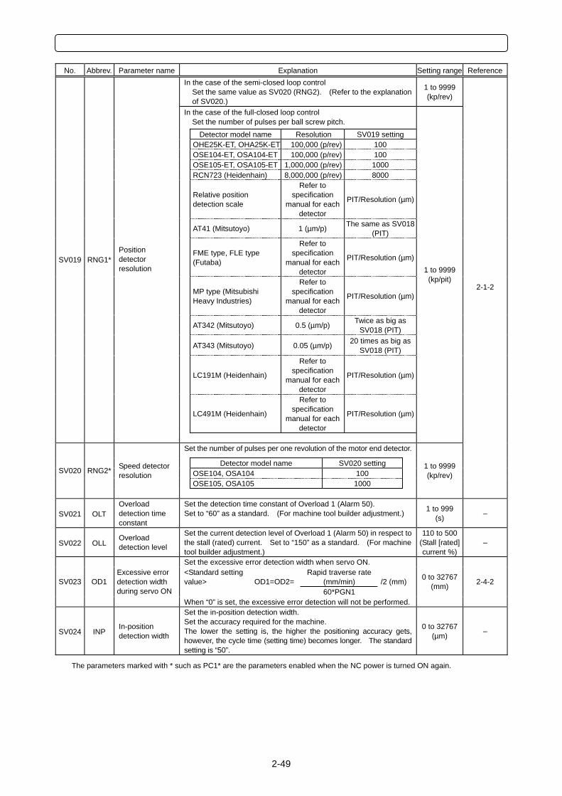
2-49
No. Abbrev. Parameter name Explanation Setting range Reference
In the case of the semi-closed loop control Set the same value as SV020 (RNG2). (Refer to the explanation of SV020.)
1 to 9999 (kp/rev)
In the case of the full-closed loop control Set the number of pulses per ball screw pitch.
Detector model name Resolution SV019 setting OHE25K-ET, OHA25K-ET 100,000 (p/rev) 100 OSE104-ET, OSA104-ET 100,000 (p/rev) 100 OSE105-ET, OSA105-ET 1,000,000 (p/rev) 1000 RCN723 (Heidenhain) 8,000,000 (p/rev) 8000
Relative position detection scale
Refer to specification
manual for each detector
PIT/Resolution (µm)
AT41 (Mitsutoyo) 1 (µm/p) The same as SV018 (PIT)
FME type, FLE type (Futaba)
Refer to specification
manual for each detector
PIT/Resolution (µm)
MP type (Mitsubishi Heavy Industries)
Refer to specification
manual for each detector
PIT/Resolution (µm)
AT342 (Mitsutoyo) 0.5 (µm/p) Twice as big as SV018 (PIT)
AT343 (Mitsutoyo) 0.05 (µm/p) 20 times as big as
SV018 (PIT)
LC191M (Heidenhain)
Refer to specification
manual for each detector
PIT/Resolution (µm)
LC491M (Heidenhain)
Refer to specification
manual for each detector
PIT/Resolution (µm)
SV019 RNG1* Position detector resolution
1 to 9999 (kp/pit)
Set the number of pulses per one revolution of the motor end detector. Detector model name SV020 setting OSE104, OSA104 100 OSE105, OSA105 1000
SV020 RNG2* Speed detector resolution
1 to 9999 (kp/rev)
2-1-2
SV021 OLT Overload detection time constant
Set the detection time constant of Overload 1 (Alarm 50). Set to “60” as a standard. (For machine tool builder adjustment.) 1 to 999
(s) –
SV022 OLL Overload detection level
Set the current detection level of Overload 1 (Alarm 50) in respect to the stall (rated) current. Set to “150” as a standard. (For machine tool builder adjustment.)
110 to 500 (Stall [rated] current %)
–
Set the excessive error detection width when servo ON. Rapid traverse rate
(mm/min) <Standard setting value> OD1=OD2=
60*PGN1 /2 (mm) SV023 OD1
Excessive error detection width during servo ON
When “0” is set, the excessive error detection will not be performed.
0 to 32767 (mm) 2-4-2
SV024 INP In-position detection width
Set the in-position detection width. Set the accuracy required for the machine. The lower the setting is, the higher the positioning accuracy gets, however, the cycle time (setting time) becomes longer. The standard setting is “50”.
0 to 32767 (µm) –
The parameters marked with * such as PC1* are the parameters enabled when the NC power is turned ON again.
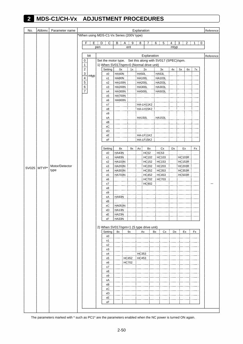
2 MDS-C1/CH-Vx ADJUSTMENT PROCEDURES
2-50
No. Abbrev. Parameter name Explanation Reference
**When using MDS-C1-Vx Series (200V type)
F E D C B A 9 8 7 6 5 4 3 2 1 0 pen ent mtyp
bit Explanation Reference 0 Set the motor type. Set this along with SV017 (SPEC)/spm. 1 1) When SV017/spm=0 (Normal drive unit) 2 Setting 0x 1x 2x 3x 4x 5x 6x 7x 3 x0 HA40N HA50L HA53L 4
mtyp x1 HA80N HA100L HA103L
5 x2 HA100N HA200L HA203L 6 x3 HA200N HA300L HA303L 7 x4 HA300N HA500L HA503L x5 HA700N x6 HA900N x7 HA-LH11K2 x8 HA-LH15K2 x9 xA HA150L HA153L xB xC xD xE HA-LF11K2 xF HA-LF15K2 Setting 8x 9x Ax Bx Cx Dx Ex Fx x0 HA43N HC52 HC53 x1 HA83N HC102 HC103 HC103R x2 HA103N HC152 HC153 HC153R
x3 HA203N HC202 HC203 HC203R SV025 MTYP* Motor/Detector type x4 HA303N HC352 HC353 HC353R
x5 HA703N HC452 HC453 HC503R x6 HC702 HC703
x7 HC902 – x8
x9 xA HA93N xB xC HA053N xD HA13N xE HA23N xF HA33N 2) When SV017/spm=1 (S type drive unit) Setting 8x 9x Ax Bx Cx Dx Ex Fx x0 x1 x2 x3 x4 HC353 x5 HC452 HC453 x6 HC702 x7 x8 x9 xA xB xC xD xE xF
The parameters marked with * such as PC1* are the parameters enabled when the NC power is turned ON again.
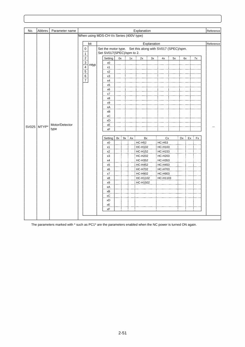
2-51
No. Abbrev. Parameter name Explanation Reference
*When using MDS-CH-Vx Series (400V type)
bit Explanation Reference
0 1
Set the motor type. Set this along with SV017 (SPEC)/spm. Set SV017(SPEC)/spm to 2.
2 Setting 0x 1x 2x 3x 4x 5x 6x 7x 3 x0 4
mtyp x1
5 x2 6 x3 7 x4 x5 x6 x7 x8 x9 xA xB xC xD
xE SV025 MTYP* Motor/Detector type xF
–
Setting 8x 9x Ax Bx Cx Dx Ex Fx x0 HC-H52 HC-H53 x1 HC-H102 HC-H103 x2 HC-H152 HC-H153
x3 HC-H202 HC-H203 x4 HC-H352 HC-H353
x5 HC-H452 HC-H453 x6 HC-H702 HC-H703
x7 HC-H902 HC-H903 x8 HC-H1102 HC-H1103
x9 HC-H1502 xA xB xC xD xE xF
The parameters marked with * such as PC1* are the parameters enabled when the NC power is turned ON again.
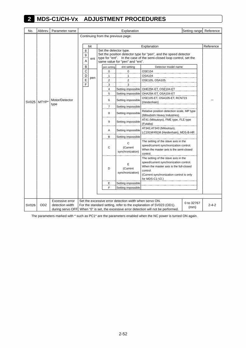
2 MDS-C1/CH-Vx ADJUSTMENT PROCEDURES
2-52
No. Abbrev. Parameter name Explanation Setting range Reference
Continuing from the previous page.
bit Explanation Reference 8
9
A ent
Set the detector type. Set the position detector type for “pen”, and the speed detector type for “ent”. In the case of the semi-closed loop control, set the same value for “pen” and “ent”.
B pen setting ent setting Detector model name C 0 0 OSE104 D 1 1 OSA104 E
pen 2 2 OSE105, OSA105
F 3 3 4 Setting impossible OHE25K-ET, OSE104-ET 5 Setting impossible OHA25K-ET, OSA104-ET
6 Setting impossibleOSE105-ET, OSA105-ET, RCN723 (Heidenhain)
– SV025 MTYP* Motor/Detector type
7 Setting impossible
8 Setting impossibleRelative position detection scale, MP type (Mitsubishi Heavy Industries)
9 Setting impossibleAT41 (Mitsutoyo), FME type, FLE type (Futaba)
A Setting impossibleAT342,AT343 (Mitsutoyo), LC191M/491M (Heidenhain), MDS-B-HR
B Setting impossible
C C
(Current synchronization)
The setting of the slave axis in the speed/current synchronization control. When the master axis is the semi-closed control.
D E
(Current synchronization)
The setting of the slave axis in the speed/current synchronization control. When the master axis is the full-closed control. (Current synchronization control is only for MDS-C1-V2.)
E Setting impossible F Setting impossible
SV026 OD2 Excessive error detection width during servo OFF
Set the excessive error detection width when servo ON. For the standard setting, refer to the explanation of SV023 (OD1). When “0” is set, the excessive error detection will not be performed.
0 to 32767 (mm) 2-4-2
The parameters marked with * such as PC1* are the parameters enabled when the NC power is turned ON again.
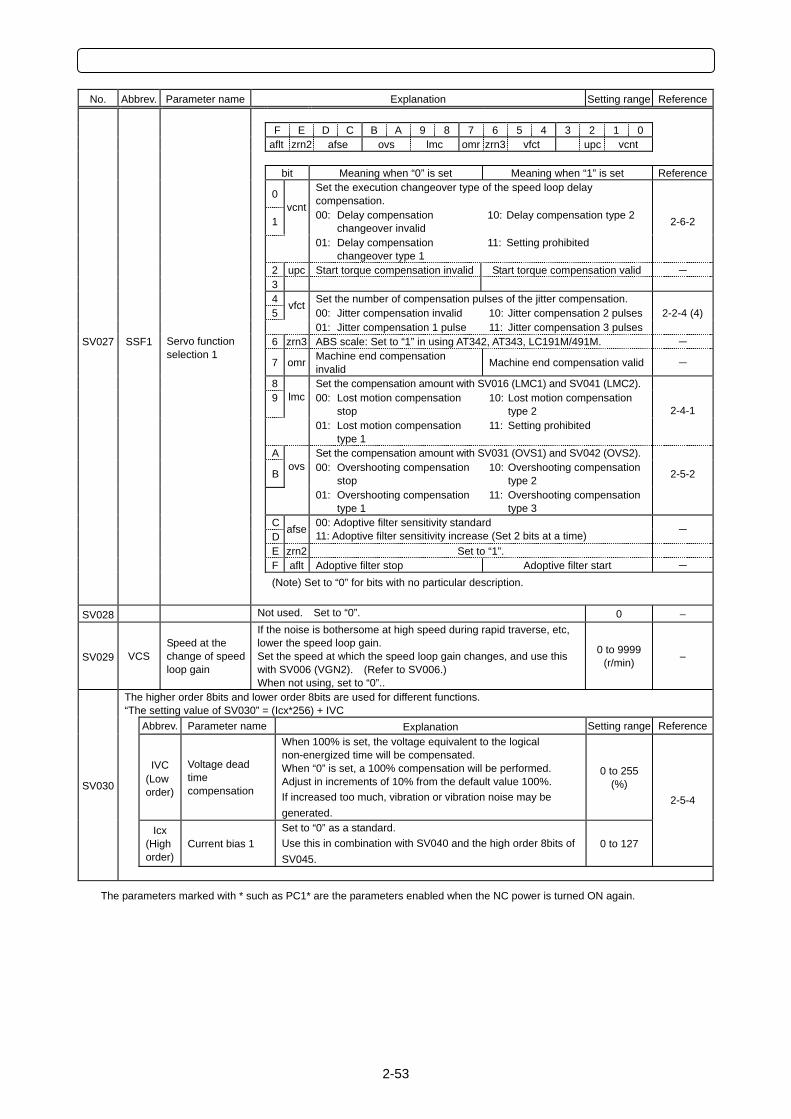
2-53
No. Abbrev. Parameter name Explanation Setting range Reference
F E D C B A 9 8 7 6 5 4 3 2 1 0 aflt zrn2 afse ovs lmc omr zrn3 vfct upc vcnt bit Meaning when “0” is set Meaning when “1” is set Reference
0 Set the execution changeover type of the speed loop delay compensation.
1 vcnt
00: Delay compensation changeover invalid
10: Delay compensation type 2 2-6-2
01: Delay compensation changeover type 1
11: Setting prohibited
2 upc Start torque compensation invalid Start torque compensation valid – 3 4 Set the number of compensation pulses of the jitter compensation. 5
vfct 00: Jitter compensation invalid 10: Jitter compensation 2 pulses 2-2-4 (4)
01: Jitter compensation 1 pulse 11: Jitter compensation 3 pulses SV027 SSF1 6 zrn3 ABS scale: Set to “1” in using AT342, AT343, LC191M/491M. –
Servo function selection 1
7 omr Machine end compensation invalid Machine end compensation valid –
8 Set the compensation amount with SV016 (LMC1) and SV041 (LMC2).
9 lmc 00: Lost motion compensation stop
10: Lost motion compensation type 2
01: Lost motion compensation type 1
11: Setting prohibited
2-4-1
A Set the compensation amount with SV031 (OVS1) and SV042 (OVS2).
B ovs 00: Overshooting compensation
stop 10: Overshooting compensation
type 2 2-5-2
01: Overshooting compensation type 1
11: Overshooting compensation type 3
C D
afse 00: Adoptive filter sensitivity standard 11: Adoptive filter sensitivity increase (Set 2 bits at a time) –
E zrn2 Set to “1”. F aflt Adoptive filter stop Adoptive filter start –
(Note) Set to “0” for bits with no particular description.
SV028 Not used. Set to “0”. 0 –
SV029 VCS Speed at the change of speed loop gain
If the noise is bothersome at high speed during rapid traverse, etc, lower the speed loop gain. Set the speed at which the speed loop gain changes, and use this with SV006 (VGN2). (Refer to SV006.) When not using, set to “0”..
0 to 9999 (r/min) –
The higher order 8bits and lower order 8bits are used for different functions. “The setting value of SV030” = (Icx*256) + IVC Abbrev. Parameter name Explanation Setting range Reference
IVC
(Low order)
Voltage dead time compensation
When 100% is set, the voltage equivalent to the logical non-energized time will be compensated. When “0” is set, a 100% compensation will be performed. Adjust in increments of 10% from the default value 100%. If increased too much, vibration or vibration noise may be generated.
0 to 255 (%)
Icx
(High order)
Current bias 1 Set to “0” as a standard. Use this in combination with SV040 and the high order 8bits of SV045.
0 to 127
2-5-4 SV030
The parameters marked with * such as PC1* are the parameters enabled when the NC power is turned ON again.
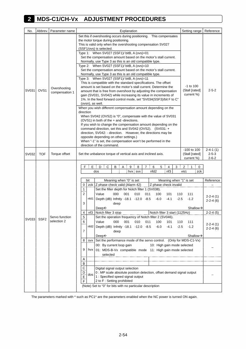
2 MDS-C1/CH-Vx ADJUSTMENT PROCEDURES
2-54
No. Abbrev. Parameter name Explanation Setting range Reference
Set this if overshooting occurs during positioning. This compensates the motor torque during positioning. This is valid only when the overshooting compensation SV027 (SSF1/ovs) is selected. Type 1: When SV027 (SSF1)/ bitB, A (ovs)=01
Set the compensation amount based on the motor’s stall current. Normally, use Type 3 as this is an old compatible type.
Type 2: When SV027 (SSF1)/ bitB, A (ovs)=10 Set the compensation amount based on the motor’s stall current. Normally, use Type 3 as this is an old compatible type.
Type 3: When SV027 (SSF1)/ bitB, A (ovs)=11 This is compatible with the standard specifications. The offset amount is set based on the motor’s stall current. Determine the amount that is free from overshoot by adjusting the compensation gain (SV031, SV042) while increasing its value in increments of 1%. In the feed forward control mode, set “SV034(SSF3)/bit F to C” (ovsn), as well.
SV031 OVS1 Overshooting compensation 1
When you wish different compensation amount depending on the direction
When SV042 (OVS2) is “0”, compensate with the value of SV031 (OVS1) in both of the + and -directions. If you wish to change the compensation amount depending on the command direction, set this and SV042 (OVS2). (SV031: + direction, SV042: - direction. However, the directions may be opposite depending on other settings.) When “-1” is set, the compensation won’t be performed in the direction of the command.
-1 to 100 (Stall [rated] current %)
2-5-2
SV032 TOF Torque offset Set the unbalance torque of vertical axis and inclined axis. -100 to 100 (Stall [rated] current %)
2-4-1 (1)2-5-3 2-6-2
F E D C B A 9 8 7 6 5 4 3 2 1 0 dos hvx svx nfd2 nf3 nfd1 zck bit Meaning when “0” is set Meaning when “1” is set Reference 0 zck Z phase check valid (Alarm 42) Z phase check invalid – 1 Set the filter depth for Notch filter 1 (SV038). 2 Value 000 001 010 011 100 101 110 111
3 nfd1 Depth (dB)
Deep
Infntly deep
-18.1 -12.0 -8.5 -6.0 -4.1 -2.5 -1.2
Shallow
2-2-4 (1)2-2-4 (6)
4 nf3 Notch filter 3 stop Notch filter 3 start (1125Hz) 2-2-4 (5) 5 Set the operation frequency of Notch filter 2 (SV046).
SV033 SSF2 6 Value 000 001 010 011 100 101 110 111
Servo function selection 2
7 nfd2 Depth (dB)
Deep
Infntly deep
-18.1 -12.0 -8.5 -6.0 -4.1 -2.5 -1.2 Shallow
2-2-4 (1)2-2-4 (6)
8 svx Set the performance mode of the servo control. (Only for MDS-C1-Vx) 00: By current loop gain 10: High gain mode selected
9 hvx 01: MDS-B-Vx compatible mode selected
11: High gain mode selected –
A B C D E
dos
F
Digital signal output selection 0 : MP scale absolute position detection, offset demand signal output 1 : Specified speed signal output 2 to F : Setting prohibited
–
(Note) Set to “0” for bits with no particular description
The parameters marked with * such as PC1* are the parameters enabled when the NC power is turned ON again.
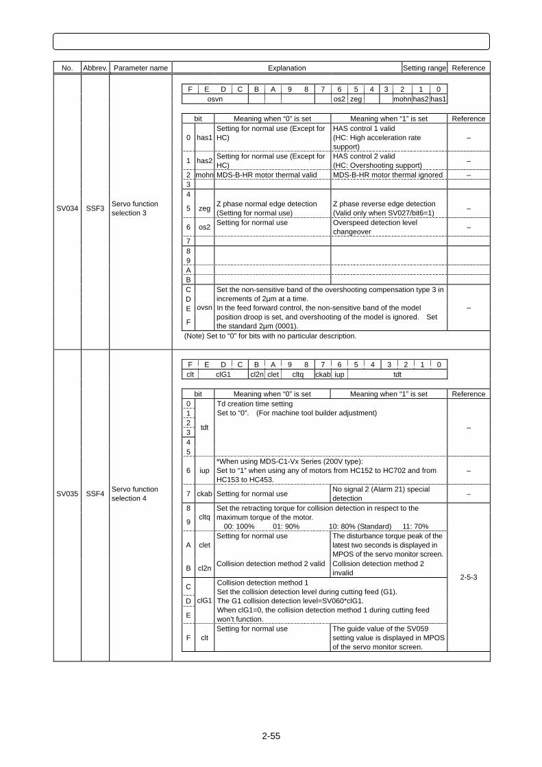
2-55
No. Abbrev. Parameter name Explanation Setting range Reference
F E D C B A 9 8 7 6 5 4 3 2 1 0 osvn os2 zeg mohn has2 has1 bit Meaning when “0” is set Meaning when “1” is set Reference
0 has1 Setting for normal use (Except for HC)
HAS control 1 valid (HC: High acceleration rate support)
–
1 has2 Setting for normal use (Except for HC)
HAS control 2 valid (HC: Overshooting support) –
2 mohn MDS-B-HR motor thermal valid MDS-B-HR motor thermal ignored – 3 4
SV034 SSF3 Servo function selection 3 5 zeg Z phase normal edge detection
(Setting for normal use) Z phase reverse edge detection (Valid only when SV027/bit6=1) –
6 os2 Setting for normal use Overspeed detection level changeover –
7 8 9 A B C D E
F
ovsn
Set the non-sensitive band of the overshooting compensation type 3 in increments of 2µm at a time. In the feed forward control, the non-sensitive band of the model position droop is set, and overshooting of the model is ignored. Set the standard 2µm (0001).
–
(Note) Set to “0” for bits with no particular description.
F E D C B A 9 8 7 6 5 4 3 2 1 0 clt clG1 cl2n clet cltq ckab iup tdt bit Meaning when “0” is set Meaning when “1” is set Reference 0 1 2 3 4 5
tdt
Td creation time setting Set to “0”. (For machine tool builder adjustment)
–
6 iup *When using MDS-C1-Vx Series (200V type): Set to “1” when using any of motors from HC152 to HC702 and from HC153 to HC453.
–
SV035 SSF4 Servo function selection 4 7 ckab Setting for normal use No signal 2 (Alarm 21) special
detection –
8
9 cltq
Set the retracting torque for collision detection in respect to the maximum torque of the motor. 00: 100% 01: 90% 10: 80% (Standard) 11: 70%
A clet Setting for normal use The disturbance torque peak of the
latest two seconds is displayed in MPOS of the servo monitor screen.
B cl2n Collision detection method 2 valid Collision detection method 2 invalid
C
D
E
clG1
Collision detection method 1 Set the collision detection level during cutting feed (G1). The G1 collision detection level=SV060*clG1. When clG1=0, the collision detection method 1 during cutting feed won’t function.
F clt Setting for normal use The guide value of the SV059
setting value is displayed in MPOS of the servo monitor screen.
2-5-3
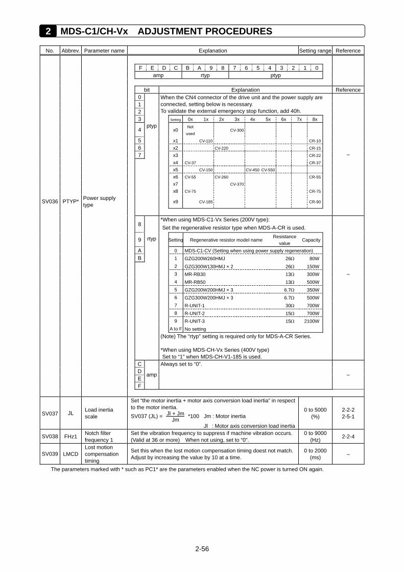
2 MDS-C1/CH-Vx ADJUSTMENT PROCEDURES
2-56
No. Abbrev. Parameter name Explanation Setting range Reference
F E D C B A 9 8 7 6 5 4 3 2 1 0 amp rtyp ptyp bit Explanation Reference 0 1 2
When the CN4 connector of the drive unit and the power supply are connected, setting below is necessary. To validate the external emergency stop function, add 40h.
3 Setting 0x 1x 2x 3x 4x 5x 6x 7x 8x
4 x0Not
used CV-300
5 x1 CV-110 CR-10 6 x2 CV-220 CR-15 7
ptyp
x3 CR-22 x4 CV-37 CR-37 x5 CV-150 CV-450 CV-550 x6 CV-55 CV-260 CR-55 x7 CV-370 x8 CV-75 CR-75
SV036 PTYP* Power supply type x9 CV-185 CR-90
–
8 *When using MDS-C1-Vx Series (200V type): Set the regenerative resistor type when MDS-A-CR is used.
9 Setting Regenerative resistor model name Resistance
value Capacity
A 0 MDS-C1-CV (Setting when using power supply regeneration) B
rtyp
1 GZG200W260HMJ 26Ω 80W 2 GZG300W130HMJ × 2 26Ω 150W 3 MR-RB30 13Ω 300W 4 MR-RB50 13Ω 500W 5 GZG200W200HMJ × 3 6.7Ω 350W 6 GZG300W200HMJ × 3 6.7Ω 500W 7 R-UNIT-1 30Ω 700W 8 R-UNIT-2 15Ω 700W 9 R-UNIT-3 15Ω 2100W A to F No setting
–
(Note) The “rtyp” setting is required only for MDS-A-CR Series. *When using MDS-CH-Vx Series (400V type) Set to “1” when MDS-CH-V1-185 is used.
C D E F
amp
Always set to “0”.
–
SV037 JL Load inertia scale
Set “the motor inertia + motor axis conversion load inertia” in respect to the motor inertia. SV037 (JL) = Jl + Jm
Jm *100 Jm : Motor inertia
Jl : Motor axis conversion load inertia
0 to 5000 (%)
2-2-2 2-5-1
SV038 FHz1 Notch filter frequency 1
Set the vibration frequency to suppress if machine vibration occurs. (Valid at 36 or more) When not using, set to “0”.
0 to 9000 (Hz) 2-2-4
SV039 LMCD Lost motion compensation timing
Set this when the lost motion compensation timing doest not match. Adjust by increasing the value by 10 at a time.
0 to 2000 (ms) –
The parameters marked with * such as PC1* are the parameters enabled when the NC power is turned ON again.
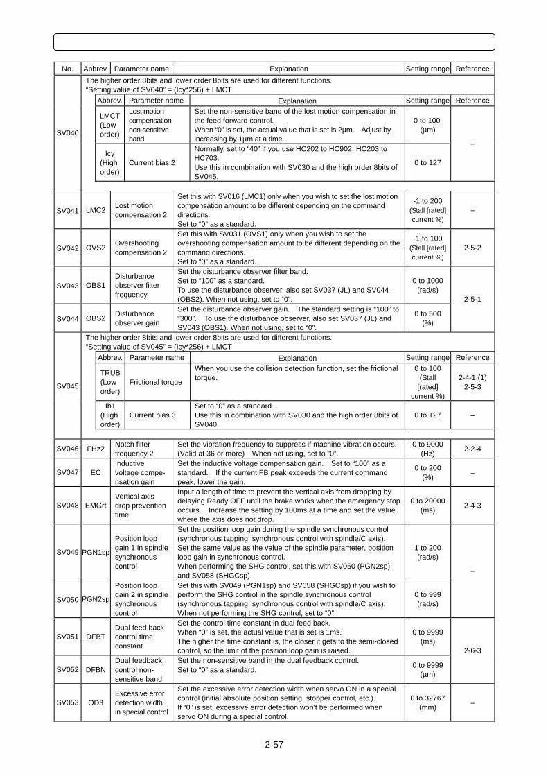
2-57
No. Abbrev. Parameter name Explanation Setting range Reference
The higher order 8bits and lower order 8bits are used for different functions. “Setting value of SV040” = (Icy*256) + LMCT Abbrev. Parameter name Explanation Setting range Reference
LMCT (Low order)
Lost motion compensation non-sensitive band
Set the non-sensitive band of the lost motion compensation in the feed forward control. When “0” is set, the actual value that is set is 2µm. Adjust by increasing by 1µm at a time.
0 to 100 (µm)
Icy
(High order)
Current bias 2
Normally, set to “40” if you use HC202 to HC902, HC203 to HC703. Use this in combination with SV030 and the high order 8bits of SV045.
0 to 127
– SV040
SV041 LMC2 Lost motion compensation 2
Set this with SV016 (LMC1) only when you wish to set the lost motion compensation amount to be different depending on the command directions. Set to “0” as a standard.
-1 to 200 (Stall [rated] current %)
–
SV042 OVS2 Overshooting compensation 2
Set this with SV031 (OVS1) only when you wish to set the overshooting compensation amount to be different depending on the command directions. Set to “0” as a standard.
-1 to 100 (Stall [rated] current %)
2-5-2
SV043 OBS1 Disturbance observer filter frequency
Set the disturbance observer filter band. Set to “100” as a standard. To use the disturbance observer, also set SV037 (JL) and SV044 (OBS2). When not using, set to “0”.
0 to 1000 (rad/s)
SV044 OBS2 Disturbance observer gain
Set the disturbance observer gain. The standard setting is “100” to “300”. To use the disturbance observer, also set SV037 (JL) and SV043 (OBS1). When not using, set to “0”.
0 to 500 (%)
2-5-1
The higher order 8bits and lower order 8bits are used for different functions. “Setting value of SV045” = (Icy*256) + LMCT Abbrev. Parameter name Explanation Setting range Reference
TRUB (Low order)
Frictional torque
When you use the collision detection function, set the frictional torque.
0 to 100 (Stall
[rated] current %)
2-4-1 (1)2-5-3
Ib1
(High order)
Current bias 3 Set to “0” as a standard. Use this in combination with SV030 and the high order 8bits of SV040.
0 to 127 –
SV045
SV046 FHz2 Notch filter frequency 2
Set the vibration frequency to suppress if machine vibration occurs. (Valid at 36 or more) When not using, set to “0”.
0 to 9000 (Hz) 2-2-4
SV047 EC Inductive voltage compe- nsation gain
Set the inductive voltage compensation gain. Set to “100” as a standard. If the current FB peak exceeds the current command peak, lower the gain.
0 to 200 (%) –
SV048 EMGrt Vertical axis drop prevention time
Input a length of time to prevent the vertical axis from dropping by delaying Ready OFF until the brake works when the emergency stop occurs. Increase the setting by 100ms at a time and set the value where the axis does not drop.
0 to 20000 (ms) 2-4-3
SV049 PGN1sp
Position loop gain 1 in spindle synchronous control
Set the position loop gain during the spindle synchronous control (synchronous tapping, synchronous control with spindle/C axis). Set the same value as the value of the spindle parameter, position loop gain in synchronous control. When performing the SHG control, set this with SV050 (PGN2sp) and SV058 (SHGCsp).
1 to 200 (rad/s)
SV050 PGN2sp
Position loop gain 2 in spindle synchronous control
Set this with SV049 (PGN1sp) and SV058 (SHGCsp) if you wish to perform the SHG control in the spindle synchronous control (synchronous tapping, synchronous control with spindle/C axis). When not performing the SHG control, set to “0”.
0 to 999 (rad/s)
–
SV051 DFBT Dual feed back control time constant
Set the control time constant in dual feed back. When “0” is set, the actual value that is set is 1ms. The higher the time constant is, the closer it gets to the semi-closed control, so the limit of the position loop gain is raised.
0 to 9999 (ms)
SV052 DFBN Dual feedback control non- sensitive band
Set the non-sensitive band in the dual feedback control. Set to “0” as a standard. 0 to 9999
(µm)
2-6-3
SV053 OD3 Excessive error detection width in special control
Set the excessive error detection width when servo ON in a special control (initial absolute position setting, stopper control, etc.). If “0” is set, excessive error detection won’t be performed when servo ON during a special control.
0 to 32767 (mm) –
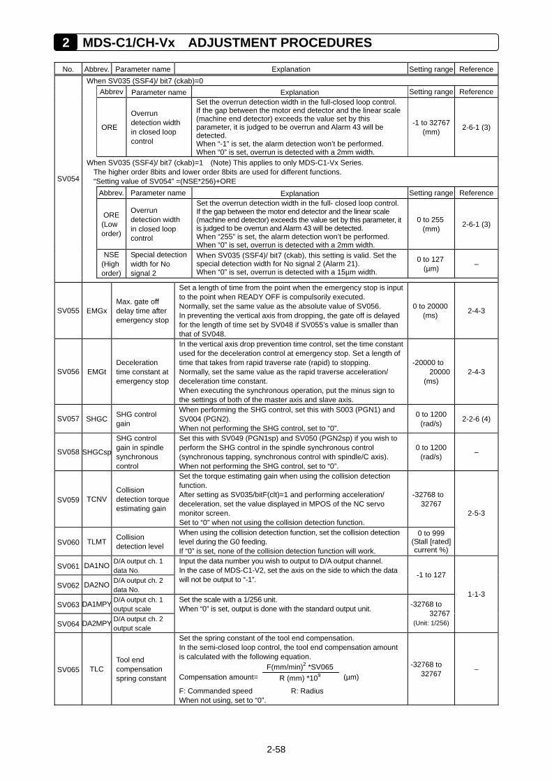
2 MDS-C1/CH-Vx ADJUSTMENT PROCEDURES
2-58
No. Abbrev. Parameter name Explanation Setting range Reference
When SV035 (SSF4)/ bit7 (ckab)=0 Abbrev Parameter name Explanation Setting range Reference
ORE
Overrun detection width in closed loop control
Set the overrun detection width in the full-closed loop control. If the gap between the motor end detector and the linear scale (machine end detector) exceeds the value set by this parameter, it is judged to be overrun and Alarm 43 will be detected. When “-1” is set, the alarm detection won’t be performed. When “0” is set, overrun is detected with a 2mm width.
-1 to 32767 (mm) 2-6-1 (3)
When SV035 (SSF4)/ bit7 (ckab)=1 (Note) This applies to only MDS-C1-Vx Series. The higher order 8bits and lower order 8bits are used for different functions. “Setting value of SV054” =(NSE*256)+ORE
Abbrev. Parameter name Explanation Setting range Reference
ORE (Low order)
Overrun detection width in closed loop control
Set the overrun detection width in the full- closed loop control. If the gap between the motor end detector and the linear scale (machine end detector) exceeds the value set by this parameter, it is judged to be overrun and Alarm 43 will be detected. When “255” is set, the alarm detection won’t be performed. When “0” is set, overrun is detected with a 2mm width.
0 to 255 (mm) 2-6-1 (3)
NSE
(High order)
Special detection width for No signal 2
When SV035 (SSF4)/ bit7 (ckab), this setting is valid. Set the special detection width for No signal 2 (Alarm 21). When “0” is set, overrun is detected with a 15µm width.
0 to 127 (µm) –
SV054
SV055 EMGx Max. gate off delay time after emergency stop
Set a length of time from the point when the emergency stop is input to the point when READY OFF is compulsorily executed. Normally, set the same value as the absolute value of SV056. In preventing the vertical axis from dropping, the gate off is delayed for the length of time set by SV048 if SV055’s value is smaller than that of SV048.
0 to 20000 (ms) 2-4-3
SV056 EMGt Deceleration time constant at emergency stop
In the vertical axis drop prevention time control, set the time constant used for the deceleration control at emergency stop. Set a length of time that takes from rapid traverse rate (rapid) to stopping. Normally, set the same value as the rapid traverse acceleration/ deceleration time constant. When executing the synchronous operation, put the minus sign to the settings of both of the master axis and slave axis.
-20000 to 20000
(ms) 2-4-3
SV057 SHGC SHG control gain
When performing the SHG control, set this with S003 (PGN1) and SV004 (PGN2). When not performing the SHG control, set to “0”.
0 to 1200 (rad/s) 2-2-6 (4)
SV058 SHGCsp
SHG control gain in spindle synchronous control
Set this with SV049 (PGN1sp) and SV050 (PGN2sp) if you wish to perform the SHG control in the spindle synchronous control (synchronous tapping, synchronous control with spindle/C axis). When not performing the SHG control, set to “0”.
0 to 1200 (rad/s) –
SV059 TCNV Collision detection torque estimating gain
Set the torque estimating gain when using the collision detection function. After setting as SV035/bitF(clt)=1 and performing acceleration/ deceleration, set the value displayed in MPOS of the NC servo monitor screen. Set to “0” when not using the collision detection function.
-32768 to 32767
SV060 TLMT Collision detection level
When using the collision detection function, set the collision detection level during the G0 feeding. If “0” is set, none of the collision detection function will work.
0 to 999 (Stall [rated] current %)
2-5-3
SV061 DA1NO D/A output ch. 1 data No.
SV062 DA2NO D/A output ch. 2 data No.
Input the data number you wish to output to D/A output channel. In the case of MDS-C1-V2, set the axis on the side to which the data will not be output to “-1”. -1 to 127
SV063 DA1MPY D/A output ch. 1 output scale
SV064 DA2MPY D/A output ch. 2 output scale
Set the scale with a 1/256 unit. When “0” is set, output is done with the standard output unit. -32768 to
32767 (Unit: 1/256)
1-1-3
SV065 TLC Tool end compensation spring constant
Set the spring constant of the tool end compensation. In the semi-closed loop control, the tool end compensation amount is calculated with the following equation.
Compensation amount= F(mm/min)2 *SV065
R (mm) *109 (µm)
F: Commanded speed R: Radius When not using, set to “0”.
-32768 to 32767 –
3-1
3 MDS-B-SVJ2 ADJUSTMENT PROCEDURES
3-1 Setting Initial Parameters ..........................................................3-3
3-1-1 Setting the gear ratio .............................................................................3-3 3-1-2 Initial settings of speed loop gain...........................................................3-3 3-1-3 Confirming the machine specifications value.........................................3-3
3-2 Gain Adjustment ........................................................................3-4
3-2-1 Preparation Before Operation ................................................................3-4 3-2-2 Measuring the inertia rate ......................................................................3-6 3-2-3 Determining the standard speed loop gain ............................................3-8 3-2-4 Explanation of resonance suppression filter ..........................................3-9 3-2-5 Adjusting the adaptive filter..................................................................3-10 3-2-6 Explanation of notch filter ....................................................................3-11 3-2-7 Adjusting the speed loop gain..............................................................3-14 3-2-8 Adjusting the position droop waveform ................................................3-16
3-3 Adjusting Acceleration/Deceleration Time Constant ................3-22
3-3-1 Rapid traverse feed (G0 feed) .............................................................3-22 3-3-2 Cutting feed (G1) .................................................................................3-24
3-4 Initial Adjustment for the Servo Functions ...............................3-25
3-4-1 Standard settings for the lost motion compensation ............................3-25 3-4-2 Excessive error width detection ...........................................................3-27 3-4-3 Setting deceleration control time constant ...........................................3-27 3-4-4 Adjustment procedures for vertical axis drop prevention control..........3-28
3-5 Procedures for Adjusting Each Functions................................3-29
3-5-1 Voltage non-sensitive zone (Td) compensation ...................................3-29 3-5-2 Disturbance observer function .............................................................3-30 3-5-3 Overshooting compensation ................................................................3-32 3-5-4 Collision detection function ..................................................................3-36 3-5-5 Vertical axis lifting control.....................................................................3-40
3-6 MDS-B-SVJ2 Parameter List ...................................................3-42
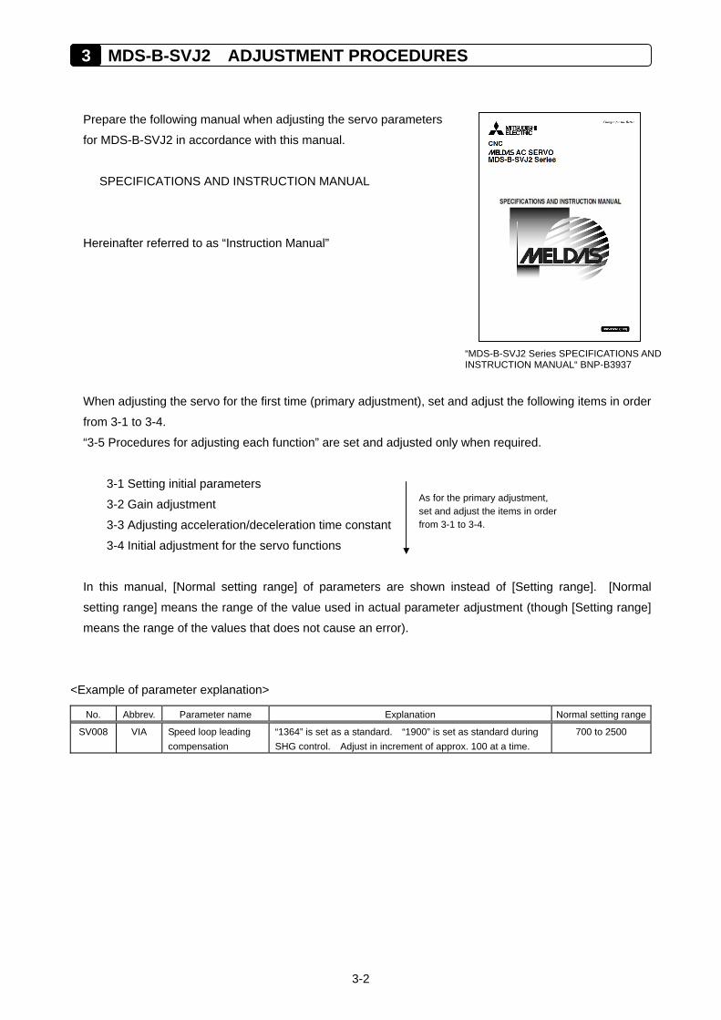
3 MDS-B-SVJ2 ADJUSTMENT PROCEDURES
3-2
Prepare the following manual when adjusting the servo parameters
for MDS-B-SVJ2 in accordance with this manual.
SPECIFICATIONS AND INSTRUCTION MANUAL
Hereinafter referred to as “Instruction Manual”
When adjusting the servo for the first time (primary adjustment), set and adjust the following items in order
from 3-1 to 3-4.
“3-5 Procedures for adjusting each function” are set and adjusted only when required.
3-1 Setting initial parameters
3-2 Gain adjustment
3-3 Adjusting acceleration/deceleration time constant
3-4 Initial adjustment for the servo functions
In this manual, [Normal setting range] of parameters are shown instead of [Setting range]. [Normal
setting range] means the range of the value used in actual parameter adjustment (though [Setting range]
means the range of the values that does not cause an error).
<Example of parameter explanation>
No. Abbrev. Parameter name Explanation Normal setting range
SV008 VIA Speed loop leading compensation
“1364” is set as a standard. “1900” is set as standard during SHG control. Adjust in increment of approx. 100 at a time.
700 to 2500
As for the primary adjustment, set and adjust the items in order from 3-1 to 3-4.
“MDS-B-SVJ2 Series SPECIFICATIONS AND INSTRUCTION MANUAL“ BNP-B3937
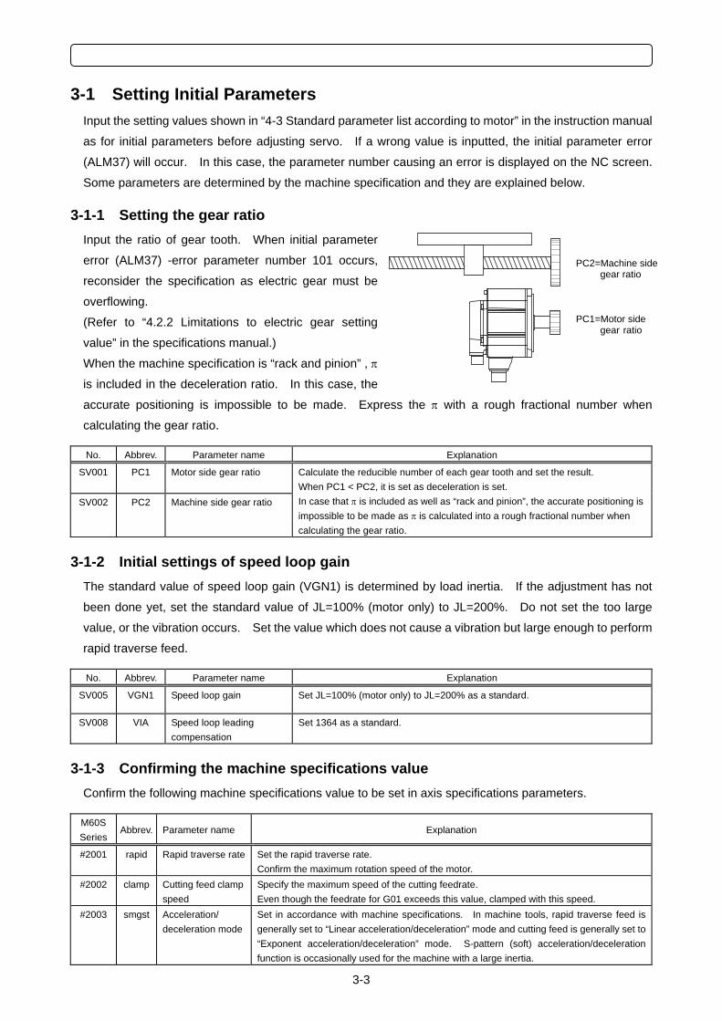
3-3
3-1 Setting Initial Parameters Input the setting values shown in “4-3 Standard parameter list according to motor” in the instruction manual
as for initial parameters before adjusting servo. If a wrong value is inputted, the initial parameter error
(ALM37) will occur. In this case, the parameter number causing an error is displayed on the NC screen.
Some parameters are determined by the machine specification and they are explained below.
3-1-1 Setting the gear ratio Input the ratio of gear tooth. When initial parameter
error (ALM37) -error parameter number 101 occurs,
reconsider the specification as electric gear must be
overflowing.
(Refer to “4.2.2 Limitations to electric gear setting
value” in the specifications manual.)
When the machine specification is “rack and pinion” , π
is included in the deceleration ratio. In this case, the
accurate positioning is impossible to be made. Express the π with a rough fractional number when
calculating the gear ratio. No. Abbrev. Parameter name Explanation
SV001
PC1 Motor side gear ratio
SV002
PC2 Machine side gear ratio
Calculate the reducible number of each gear tooth and set the result. When PC1 < PC2, it is set as deceleration is set. In case that π is included as well as “rack and pinion”, the accurate positioning is impossible to be made as π is calculated into a rough fractional number when calculating the gear ratio.
3-1-2 Initial settings of speed loop gain The standard value of speed loop gain (VGN1) is determined by load inertia. If the adjustment has not
been done yet, set the standard value of JL=100% (motor only) to JL=200%. Do not set the too large
value, or the vibration occurs. Set the value which does not cause a vibration but large enough to perform
rapid traverse feed. No. Abbrev. Parameter name Explanation
SV005 VGN1 Speed loop gain Set JL=100% (motor only) to JL=200% as a standard.
SV008 VIA Speed loop leading compensation
Set 1364 as a standard.
3-1-3 Confirming the machine specifications value Confirm the following machine specifications value to be set in axis specifications parameters. M60S Series
Abbrev. Parameter name Explanation
#2001 rapid Rapid traverse rate Set the rapid traverse rate. Confirm the maximum rotation speed of the motor.
#2002 clamp Cutting feed clamp speed
Specify the maximum speed of the cutting feedrate. Even though the feedrate for G01 exceeds this value, clamped with this speed.
#2003 smgst Acceleration/ deceleration mode
Set in accordance with machine specifications. In machine tools, rapid traverse feed is generally set to “Linear acceleration/deceleration” mode and cutting feed is generally set to “Exponent acceleration/deceleration” mode. S-pattern (soft) acceleration/deceleration function is occasionally used for the machine with a large inertia.
PC1=Motor side gear ratio
PC2=Machine side gear ratio
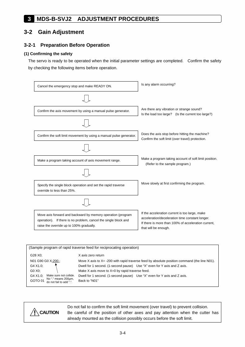
3 MDS-B-SVJ2 ADJUSTMENT PROCEDURES
3-4
3-2 Gain Adjustment
3-2-1 Preparation Before Operation (1) Confirming the safety
The servo is ready to be operated when the initial parameter settings are completed. Confirm the safety
by checking the following items before operation.
CAUTION!
Do not fail to confirm the soft limit movement (over travel) to prevent collision. Be careful of the position of other axes and pay attention when the cutter has already mounted as the collision possibly occurs before the soft limit.
(Sample program of rapid traverse feed for reciprocating operation)
G28 X0; X axis zero return
N01 G90 G0 X-200.; Move X axis to X= -200 with rapid traverse feed by absolute position command (the line N01). G4 X1.0; Dwell for 1 second. (1-second pause) Use “X” even for Y axis and Z axis. G0 X0; Make X axis move to X=0 by rapid traverse feed. G4 X1.0; Dwell for 1 second. (1-second pause) Use “X” even for Y axis and Z axis. GOTO 01 Back to “N01”
Make sure not collide. No “.” means 200µm, do not fail to add “.”.
Confirm the axis movement by using a manual pulse generator.
Cancel the emergency stop and make READY ON.
Confirm the soft limit movement by using a manual pulse generator.
Specify the single block operation and set the rapid traverse override to less than 25%.
Move axis forward and backward by memory operation (program operation). If there is no problem, cancel the single block and raise the override up to 100% gradually.
Make a program taking account of axis movement range.
Is any alarm occurring?
Are there any vibration or strange sound? Is the load too large? (Is the current too large?)
Does the axis stop before hitting the machine? Confirm the soft limit (over travel) protection.
Make a program taking account of soft limit position. (Refer to the sample program.)
If the acceleration current is too large, make acceleration/deceleration time constant longer. If there is more than 100% of acceleration current, that will be enough.
Move slowly at first confirming the program.
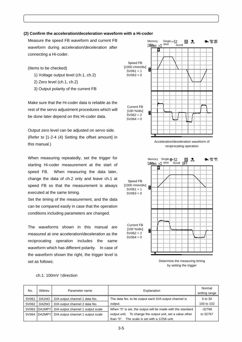
3-5
(2) Confirm the acceleration/deceleration waveform with a Hi-coder Measure the speed FB waveform and current FB
waveform during acceleration/deceleration after
connecting a Hi-coder.
(Items to be checked)
1) Voltage output level (ch.1, ch.2)
2) Zero level (ch.1, ch.2)
3) Output polarity of the current FB
Make sure that the Hi-coder data is reliable as the
rest of the servo adjustment procedures which will
be done later depend on this Hi-coder data.
Output zero level can be adjusted on servo side.
(Refer to [1-2-4 (4) Setting the offset amount] in
this manual.)
When measuring repeatedly, set the trigger for
starting Hi-coder measurement at the start of
speed FB. When measuring the data later,
change the data of ch.2 only and leave ch.1 at
speed FB so that the measurement is always
executed at the same timing.
Set the timing of the measurement, and the data
can be compared easily in case that the operation
conditions including parameters are changed.
The waveforms shown in this manual are
measured at one acceleration/deceleration as the
reciprocating operation includes the same
waveform which has different polarity. In case of
the waveform shown the right, the trigger level is
set as follows;
ch.1: 100mV ↑direction
No. Abbrev. Parameter name Explanation Normal
setting range
SV061 DA1NO D/A output channel 1 data No. SV062 DA2NO D/A output channel 2 data No.
The data No. to be output each D/A output channel is output.
0 to 30 100 to 102
SV063 DA1MPY D/A output channel 1 output scale SV064 DA2MPY D/A output channel 1 output scale
When “0” is set, the output will be made with the standard output unit. To change the output unit, set a value other than “0”. The scale is set with a 1/256 unit.
-32768 to 32767
Acceleration/deceleration waveform of reciprocating operation
Memory Single Scroll shot
Speed FB [1000 r/min/div]
SV061 = 1 SV063 = 0
Current FB [100 %/div] SV062 = 2 SV064 = 0
Determine the measuring timing by setting the trigger
Scroll Memory Single
shot
Speed FB [1000 r/min/div]
SV061 = 1 SV063 = 0
Current FB [100 %/div] SV062 = 2 SV064 = 0
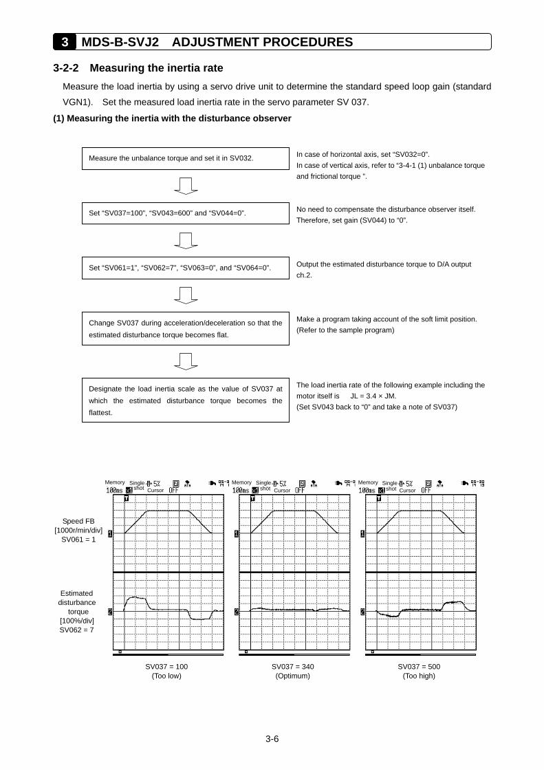
3 MDS-B-SVJ2 ADJUSTMENT PROCEDURES
3-6
3-2-2 Measuring the inertia rate Measure the load inertia by using a servo drive unit to determine the standard speed loop gain (standard
VGN1). Set the measured load inertia rate in the servo parameter SV 037.
(1) Measuring the inertia with the disturbance observer
Speed FB [1000r/min/div]
SV061 = 1
SV037 = 100 (Too low)
SV037 = 340 (Optimum)
SV037 = 500 (Too high)
Memory Single shot Cursor
Memory Single shot Cursor
Memory Single shot Cursor
Estimated disturbance
torque [100%/div] SV062 = 7
Measure the unbalance torque and set it in SV032.
Set “SV037=100”, “SV043=600” and “SV044=0”.
In case of horizontal axis, set “SV032=0”. In case of vertical axis, refer to “3-4-1 (1) unbalance torqueand frictional torque ”.
No need to compensate the disturbance observer itself. Therefore, set gain (SV044) to “0”.
Set “SV061=1”, “SV062=7”, “SV063=0”, and “SV064=0”. Output the estimated disturbance torque to D/A output ch.2.
Change SV037 during acceleration/deceleration so that theestimated disturbance torque becomes flat.
Make a program taking account of the soft limit position.(Refer to the sample program)
Designate the load inertia scale as the value of SV037 atwhich the estimated disturbance torque becomes theflattest.
The load inertia rate of the following example including themotor itself is JL = 3.4 × JM. (Set SV043 back to “0” and take a note of SV037)
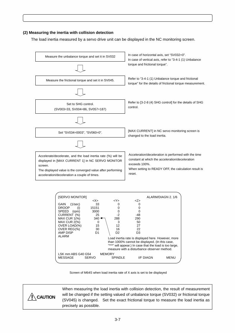
3-7
(2) Measuring the inertia with collision detection The load inertia measured by a servo drive unit can be displayed in the NC monitoring screen.
CAUTION!
When measuring the load inertia with collision detection, the result of measurement will be changed if the setting valued of unbalance torque (SV032) or frictional torque (SV045) is changed. Set the exact frictional torque to measure the load inertia as precisely as possible.
In case of horizontal axis, set “SV032=0”. In case of vertical axis, refer to “3-4-1 (1) Unbalance torque and frictional torque”.
Refer to “3-4-1 (1) Unbalance torque and frictional torque” for the details of frictional torque measurement.
Refer to [3-2-8 (4) SHG control] for the details of SHG control.
[MAX CURRENT] in NC servo monitoring screen is changed to the load inertia.
Acceleration/deceleration is performed with the time constant at which the acceleration/deceleration exceeds 100%. When setting to READY OFF, the calculation result is reset.
Measure the unbalance torque and set it in SV032
Measure the frictional torque and set it in SV045.
Set to SHG control. (SV003=33, SV004=86, SV057=187)
Set “SV034=0003”, “SV060=0”.
Accelerate/decelerate, and the load inertia rate (%) will bedisplayed in [MAX CURRENT 1] in NC SERVO MONITORscreen. The displayed value is the converged value after performingacceleration/deceleration a couple of times.
[SERVO MONITOR] ALARM/DIAGN 2. 1/6 <X> <Y> <Z> GAIN (1/sec) 33 0 0 DROOP (i) 15151 0 0 SPEED (rpm) 3000 0 0 CURRENT (%) 25 -2 -48 MAX CUR 1(%) 340 288 290 MAX CUR 2(%) 0 3 50 OVER LOAD(%) 15 12 27 OVER REG (%) 30 16 22 AMP DISP D1 D2 D3 ALARM LSK mm ABS G40 G54 MEMORY MESSAGE SERVO SPINDLE I/F DIAGN MENU
Screen of M64S when load inertia rate of X axis is set to be displayed
Load inertia rate is displayed here. However, more than 1000% cannot be displayed. (In this case, “***” will appear.) In case that the load is too large, measure with a disturbance observer method.
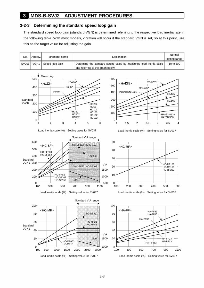
3 MDS-B-SVJ2 ADJUSTMENT PROCEDURES
3-8
3-2-3 Determining the standard speed loop gain The standard speed loop gain (standard VGN) is determined referring to the respective load inertia rate in
the following table. With most models, vibration will occur if the standard VGN is set, so at this point, use
this as the target value for adjusting the gain.
No. Abbrev. Parameter name Explanation Normal
setting range
SV005 VGN1 Speed loop gain Determine the standard setting value by measuring load inertia scale and referring to the graph below.
10 to 600
Load inertia scale (%) Setting value for SV037
10
20
0
50
40
30
100 200 400 600300 500
HC-RF103HC-RF153HC-RF203
<HC-RF>
80
60
20
40
0
100
100 500300 700 1100900
HA-FF63 HA-FF43
HA-FF33
HA-FF23HA-FF13 HA-FF053
<HA-FF>
Load inertia scale (%) Setting value for SV037
Standard VGN1
Load inertia scale (%) Setting value for SV037
20
40
0
100
80
60
1500
1000
VIA
Standard VIA range
100 500 30001000 25002000 1500
HC-MF73<HC-MF>
VIA
HC-MF23HC-MF43
HC-MF053 HC-MF13
Standard VGN1
0100 300 700 1100500 900
Standard VIA range
Load inertia scale (%) Setting value for SV037
600
100
200
500
400
300
1500
1000
HC-SF203 HC-SF353
HC-SF52 HC-SF102 HC-SF152
HC-SF202
500
VIA
VIA
<HC-SF> HC-SF352, HC-SF153
HC-SF53, HC-SF103
100
200
0
500
400
300
1 2 4 63 5
HC52 HC102 HC152
HC352* <HC >
HC202*
HC203*
HC202HC53 HC103HC153HC102*HC152*
Motor only
Standard VGN1
Load inertia scale (%) Setting value for SV037
100
200
0
600
400
300
1 2 3 41.5 2.5 3.5
HA40N
HA053N/13NHA23N/33N
HA43N
HA103N*
<HA N> 500
HA200N*
HA80N/83N/100N
Load inertia scale (%) Setting value for SV037
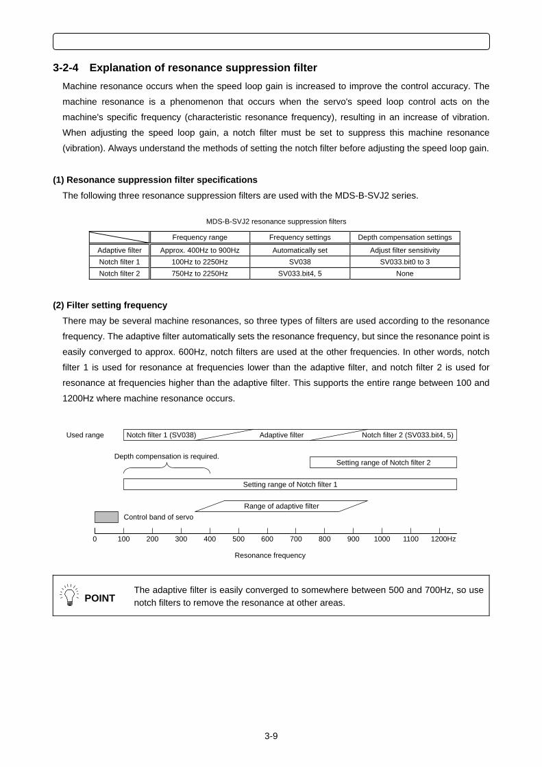
3-9
3-2-4 Explanation of resonance suppression filter Machine resonance occurs when the speed loop gain is increased to improve the control accuracy. The
machine resonance is a phenomenon that occurs when the servo's speed loop control acts on the
machine's specific frequency (characteristic resonance frequency), resulting in an increase of vibration.
When adjusting the speed loop gain, a notch filter must be set to suppress this machine resonance
(vibration). Always understand the methods of setting the notch filter before adjusting the speed loop gain.
(1) Resonance suppression filter specifications The following three resonance suppression filters are used with the MDS-B-SVJ2 series.
MDS-B-SVJ2 resonance suppression filters
Frequency range Frequency settings Depth compensation settings
Adaptive filter Approx. 400Hz to 900Hz Automatically set Adjust filter sensitivity Notch filter 1 100Hz to 2250Hz SV038 SV033.bit0 to 3 Notch filter 2 750Hz to 2250Hz SV033.bit4, 5 None
(2) Filter setting frequency There may be several machine resonances, so three types of filters are used according to the resonance
frequency. The adaptive filter automatically sets the resonance frequency, but since the resonance point is
easily converged to approx. 600Hz, notch filters are used at the other frequencies. In other words, notch
filter 1 is used for resonance at frequencies lower than the adaptive filter, and notch filter 2 is used for
resonance at frequencies higher than the adaptive filter. This supports the entire range between 100 and
1200Hz where machine resonance occurs.
POINT
The adaptive filter is easily converged to somewhere between 500 and 700Hz, so use notch filters to remove the resonance at other areas.
Control band of servo
Setting range of Notch filter 1
Range of adaptive filter
Setting range of Notch filter 2 Depth compensation is required.
Resonance frequency
Used range Adaptive filter Notch filter 2 (SV033.bit4, 5)Notch filter 1 (SV038)
0 100 200 300 400 500 600 700 800 900 1000 1200Hz1100
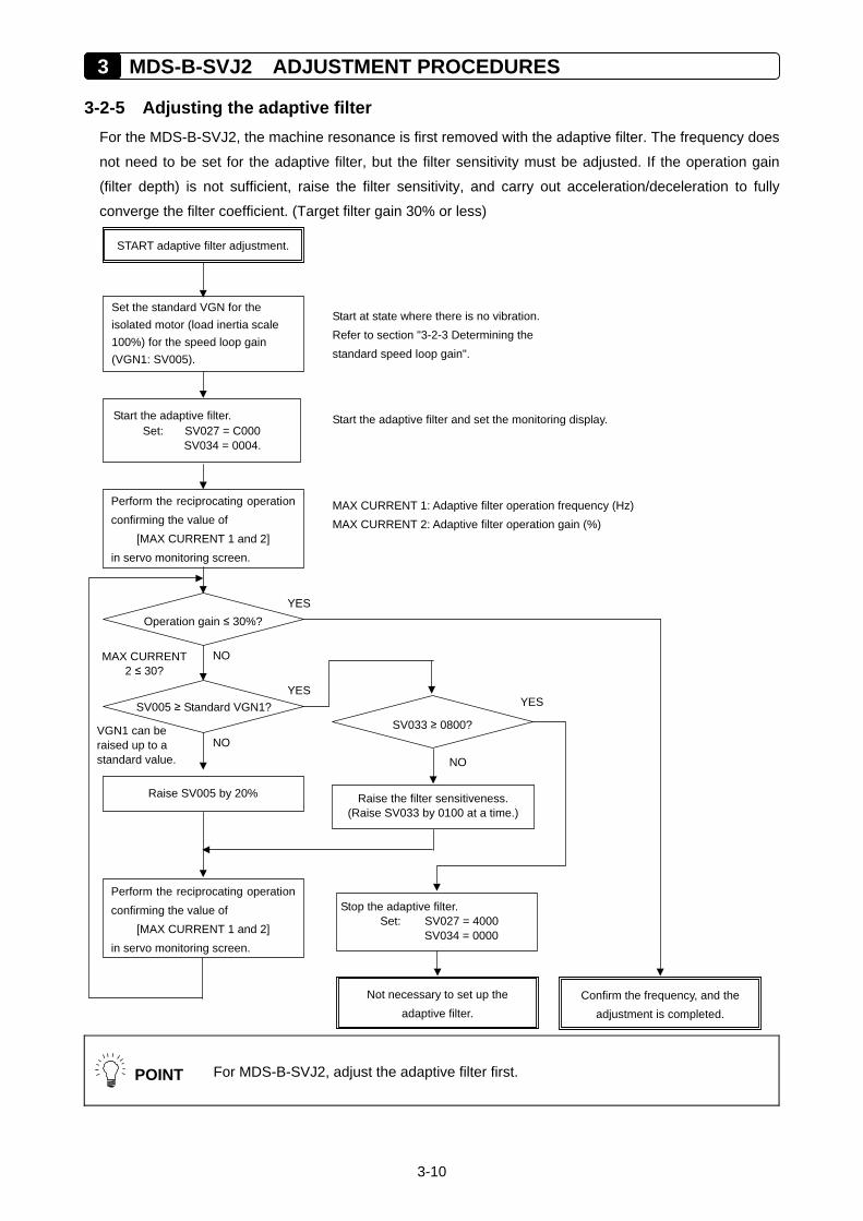
3 MDS-B-SVJ2 ADJUSTMENT PROCEDURES
3-10
3-2-5 Adjusting the adaptive filter For the MDS-B-SVJ2, the machine resonance is first removed with the adaptive filter. The frequency does
not need to be set for the adaptive filter, but the filter sensitivity must be adjusted. If the operation gain
(filter depth) is not sufficient, raise the filter sensitivity, and carry out acceleration/deceleration to fully
converge the filter coefficient. (Target filter gain 30% or less)
POINT For MDS-B-SVJ2, adjust the adaptive filter first.
Set the standard VGN for the isolated motor (load inertia scale 100%) for the speed loop gain (VGN1: SV005).
Start the adaptive filter. Set: SV027 = C000
SV034 = 0004.
Start the adaptive filter and set the monitoring display.
Perform the reciprocating operation confirming the value of
[MAX CURRENT 1 and 2] in servo monitoring screen.
Operation gain ≤ 30%?
Confirm the frequency, and the adjustment is completed.
MAX CURRENT 1: Adaptive filter operation frequency (Hz) MAX CURRENT 2: Adaptive filter operation gain (%)
Start at state where there is no vibration. Refer to section "3-2-3 Determining the standard speed loop gain".
SV005 ≥ Standard VGN1? SV033 ≥ 0800?
Raise the filter sensitiveness. (Raise SV033 by 0100 at a time.)
VGN1 can be raised up to a standard value.
START adaptive filter adjustment.
MAX CURRENT 2 ≤ 30?
YES
NO
YES
NO
Raise SV005 by 20%
YES
NO
Stop the adaptive filter. Set: SV027 = 4000
SV034 = 0000
Not necessary to set up the adaptive filter.
Perform the reciprocating operation confirming the value of
[MAX CURRENT 1 and 2] in servo monitoring screen.
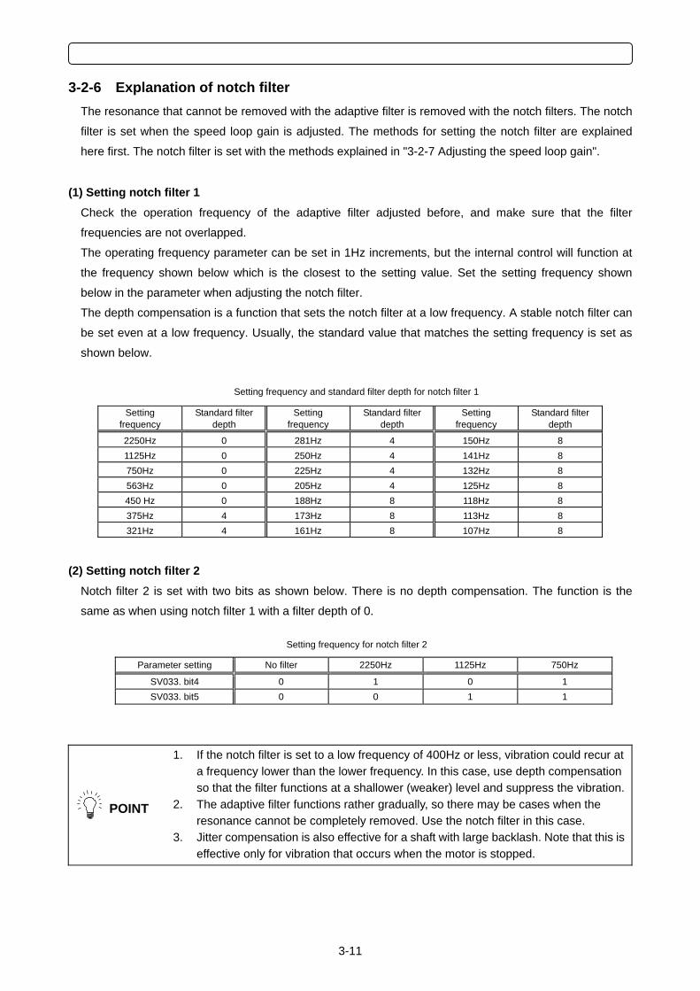
3-11
3-2-6 Explanation of notch filter The resonance that cannot be removed with the adaptive filter is removed with the notch filters. The notch
filter is set when the speed loop gain is adjusted. The methods for setting the notch filter are explained
here first. The notch filter is set with the methods explained in "3-2-7 Adjusting the speed loop gain".
(1) Setting notch filter 1 Check the operation frequency of the adaptive filter adjusted before, and make sure that the filter
frequencies are not overlapped.
The operating frequency parameter can be set in 1Hz increments, but the internal control will function at
the frequency shown below which is the closest to the setting value. Set the setting frequency shown
below in the parameter when adjusting the notch filter.
The depth compensation is a function that sets the notch filter at a low frequency. A stable notch filter can
be set even at a low frequency. Usually, the standard value that matches the setting frequency is set as
shown below.
Setting frequency and standard filter depth for notch filter 1
Setting frequency
Standard filter depth
Setting frequency
Standard filter depth
Setting frequency
Standard filter depth
2250Hz 0 281Hz 4 150Hz 8 1125Hz 0 250Hz 4 141Hz 8 750Hz 0 225Hz 4 132Hz 8 563Hz 0 205Hz 4 125Hz 8 450 Hz 0 188Hz 8 118Hz 8 375Hz 4 173Hz 8 113Hz 8 321Hz 4 161Hz 8 107Hz 8
(2) Setting notch filter 2 Notch filter 2 is set with two bits as shown below. There is no depth compensation. The function is the
same as when using notch filter 1 with a filter depth of 0.
Setting frequency for notch filter 2
Parameter setting No filter 2250Hz 1125Hz 750Hz
SV033. bit4 0 1 0 1 SV033. bit5 0 0 1 1
POINT
1. If the notch filter is set to a low frequency of 400Hz or less, vibration could recur at a frequency lower than the lower frequency. In this case, use depth compensation so that the filter functions at a shallower (weaker) level and suppress the vibration.
2. The adaptive filter functions rather gradually, so there may be cases when the resonance cannot be completely removed. Use the notch filter in this case.
3. Jitter compensation is also effective for a shaft with large backlash. Note that this is effective only for vibration that occurs when the motor is stopped.
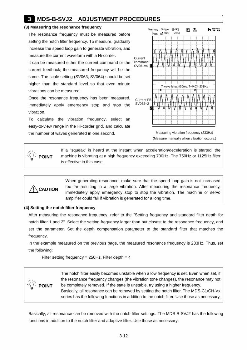
3 MDS-B-SVJ2 ADJUSTMENT PROCEDURES
3-12
Measuring vibration frequency (233Hz)
(Measure manually when vibration occurs.)
Current command.SV061=4
7 wave length/30ms: 7÷0.03=233Hz
Memory Singleshot Scroll
Current FBSV062=2
(3) Measuring the resonance frequency The resonance frequency must be measured before
setting the notch filter frequency. To measure, gradually
increase the speed loop gain to generate vibration, and
measure the current waveform with a Hi-corder.
It can be measured either the current command or the
current feedback; the measured frequency will be the
same. The scale setting (SV063, SV064) should be set
higher than the standard level so that even minute
vibrations can be measured. Once the resonance frequency has been measured,
immediately apply emergency stop and stop the
vibration. To calculate the vibration frequency, select an
easy-to-view range in the Hi-corder grid, and calculate
the number of waves generated in one second.
POINT
If a "squeak" is heard at the instant when acceleration/deceleration is started, the machine is vibrating at a high frequency exceeding 700Hz. The 750Hz or 1125Hz filter is effective in this case.
CAUTION!
When generating resonance, make sure that the speed loop gain is not increased too far resulting in a large vibration. After measuring the resonance frequency, immediately apply emergency stop to stop the vibration. The machine or servo amplifier could fail if vibration is generated for a long time.
(4) Setting the notch filter frequency After measuring the resonance frequency, refer to the "Setting frequency and standard filter depth for
notch filter 1 and 2". Select the setting frequency larger than but closest to the resonance frequency, and
set the parameter. Set the depth compensation parameter to the standard filter that matches the
frequency.
In the example measured on the previous page, the measured resonance frequency is 233Hz. Thus, set
the following:
Filter setting frequency = 250Hz, Filter depth = 4
POINT
The notch filter easily becomes unstable when a low frequency is set. Even when set, if the resonance frequency changes (the vibration tone changes), the resonance may not be completely removed. If the state is unstable, try using a higher frequency. Basically, all resonance can be removed by setting the notch filter. The MDS-C1/CH-Vx series has the following functions in addition to the notch filter. Use those as necessary.
Basically, all resonance can be removed with the notch filter settings. The MDS-B-SVJ2 has the following
functions in addition to the notch filter and adaptive filter. Use those as necessary.
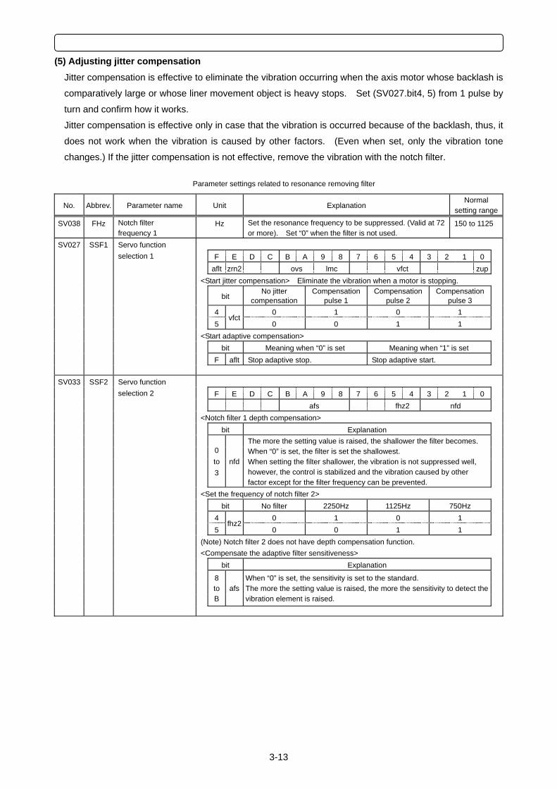
3-13
(5) Adjusting jitter compensation Jitter compensation is effective to eliminate the vibration occurring when the axis motor whose backlash is
comparatively large or whose liner movement object is heavy stops. Set (SV027.bit4, 5) from 1 pulse by
turn and confirm how it works.
Jitter compensation is effective only in case that the vibration is occurred because of the backlash, thus, it
does not work when the vibration is caused by other factors. (Even when set, only the vibration tone
changes.) If the jitter compensation is not effective, remove the vibration with the notch filter.
Parameter settings related to resonance removing filter
No. Abbrev. Parameter name Unit Explanation Normal
setting range
SV038 FHz Notch filter frequency 1
Hz Set the resonance frequency to be suppressed. (Valid at 72 or more). Set “0” when the filter is not used.
150 to 1125
SV027 SSF1 F E D C B A 9 8 7 6 5 4 3 2 1 0 aflt zrn2 ovs lmc vfct zup <Start jitter compensation> Eliminate the vibration when a motor is stopping.
bit No jitter
compensationCompensation
pulse 1 Compensation
pulse 2 Compensation
pulse 3 4 0 1 0 1 5
vfct0 0 1 1
<Start adaptive compensation> bit Meaning when “0” is set Meaning when “1” is set F aflt Stop adaptive stop. Stop adaptive start.
Servo function selection 1
SV033 SSF2 F E D C B A 9 8 7 6 5 4 3 2 1 0 afs fhz2 nfd <Notch filter 1 depth compensation> bit Explanation
0 to 3
nfd
The more the setting value is raised, the shallower the filter becomes. When “0” is set, the filter is set the shallowest. When setting the filter shallower, the vibration is not suppressed well, however, the control is stabilized and the vibration caused by other factor except for the filter frequency can be prevented.
<Set the frequency of notch filter 2> bit No filter 2250Hz 1125Hz 750Hz 4 0 1 0 1 5
fhz20 0 1 1
(Note) Notch filter 2 does not have depth compensation function. <Compensate the adaptive filter sensitiveness> bit Explanation
8 to B
afsWhen “0” is set, the sensitivity is set to the standard. The more the setting value is raised, the more the sensitivity to detect the vibration element is raised.
Servo function selection 2
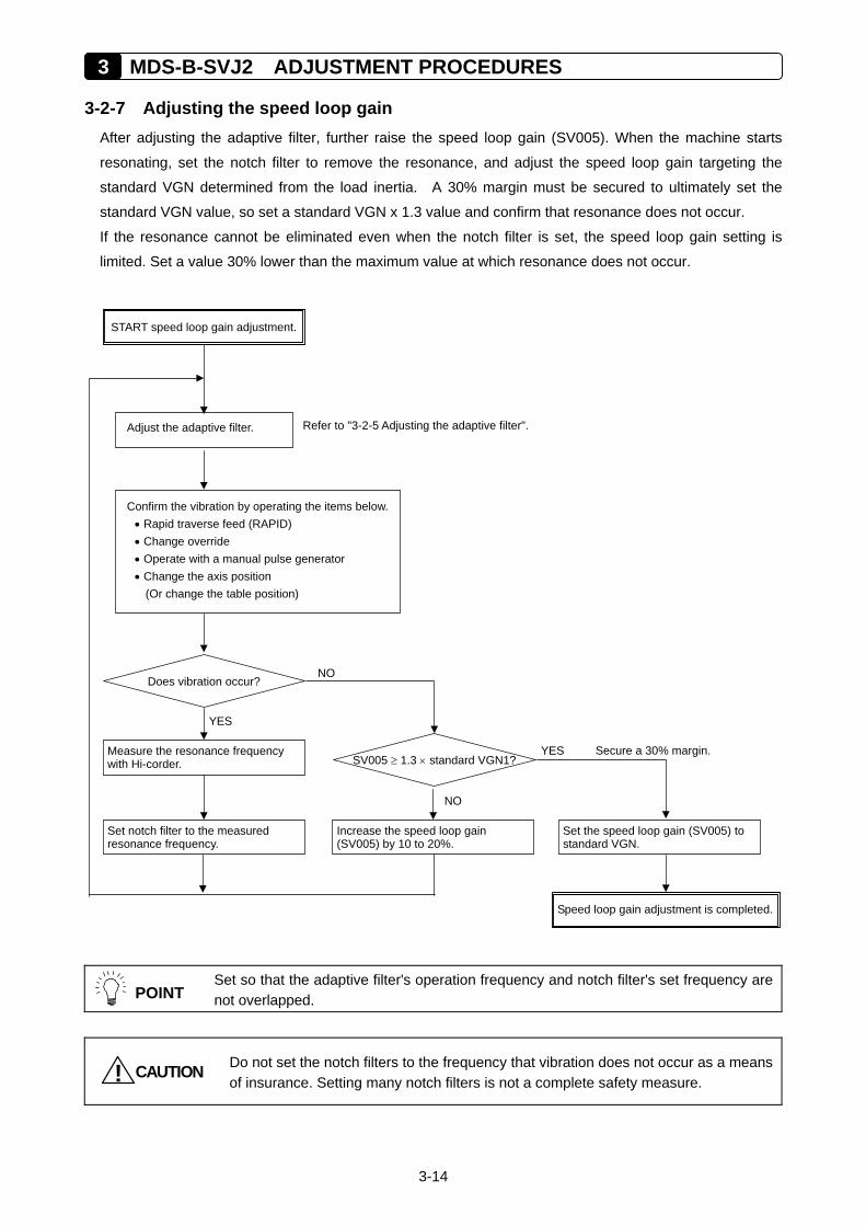
3 MDS-B-SVJ2 ADJUSTMENT PROCEDURES
3-14
3-2-7 Adjusting the speed loop gain After adjusting the adaptive filter, further raise the speed loop gain (SV005). When the machine starts
resonating, set the notch filter to remove the resonance, and adjust the speed loop gain targeting the
standard VGN determined from the load inertia. A 30% margin must be secured to ultimately set the
standard VGN value, so set a standard VGN x 1.3 value and confirm that resonance does not occur.
If the resonance cannot be eliminated even when the notch filter is set, the speed loop gain setting is
limited. Set a value 30% lower than the maximum value at which resonance does not occur.
POINT
Set so that the adaptive filter's operation frequency and notch filter's set frequency are not overlapped.
CAUTION! Do not set the notch filters to the frequency that vibration does not occur as a means of insurance. Setting many notch filters is not a complete safety measure.
Speed loop gain adjustment is completed.
START speed loop gain adjustment.
Confirm the vibration by operating the items below.• Rapid traverse feed (RAPID) • Change override • Operate with a manual pulse generator • Change the axis position
(Or change the table position)
Secure a 30% margin.
NO Does vibration occur?
YES
Adjust the adaptive filter. Refer to "3-2-5 Adjusting the adaptive filter".
Measure the resonance frequency with Hi-corder. SV005 ≥ 1.3 × standard VGN1?
Set notch filter to the measured resonance frequency.
Increase the speed loop gain (SV005) by 10 to 20%.
Set the speed loop gain (SV005) to standard VGN.
NO
YES

3-15
POINT
1. The final SV005 (VGN1) setting value is 70% of the maximum value at which machine resonance does not occur. If the resonance is suppressed and the SV005 setting is increased by using a vibration suppression function, such as a notch filter, the servo can be adjusted easier later on.
2. If the vibration is caused by resonance (mutual action of servo control and machine characteristics), the vibration can always be stopped by lowering SV005 (VGN1). If the vibration does not change even when SV005 is lowered, there may be a problem in the machine. The notch filter is not effective when there is a problem in the machine.
<<Reference material>>
Machine resonance is not the only vibration that occurs at the servo shaft. Types of vibration that occur at
the servo shaft are listed below.
Types of vibration Cause Vibration
frequency Measures Explanation
Machine resonance
Delay in servo control response 150Hz to 1kHz • Set the notch filter
• Lower VGN1 (SV005)
There may be several resonance points. The vibration can always be stopped by lowering VGN1.
Hunting The speed loop PI gain (VGN, VIA) is unbalanced
Several Hz • Lower VIA (SV008) • Raise VGN1 (SV005) • Use the disturbance observer
Visually apparent that the shaft vibrates during acceleration, or the shaft trembles when stopped.
Isolated machine vibration
Insufficient machine rigidity 10 to 20Hz
• Lower PGN1 (SV003) • Use S-pattern (soft)
acceleration/deceleration
The machine vibrates due to impact during acceleration/deceleration. A "clonk" sound may be heard during acceleration.
Is a vibration sound heard?
Isolated machine vibration
NO
Judging the type of vibration
Is the frequency low, and vibration visible?
Set standard VGN1 for isolated motor in speed loop gain (SV005).
Is a vibration sound heard only during acceleration/
deceleration?
YES
YES
NO Is a vibration sound heard?
Machine resonance
YES
NO
YES
Vibration other than servo system.(Vibration of oil pump, etc.)
NO
Does vibration occur?
NO
Hunting
YES
Set standard VGN1 for isolated motor in speed loop gain (SV005).
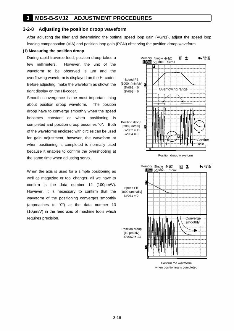
3 MDS-B-SVJ2 ADJUSTMENT PROCEDURES
3-16
3-2-8 Adjusting the position droop waveform After adjusting the filter and determining the optimal speed loop gain (VGN1), adjust the speed loop
leading compensation (VIA) and position loop gain (PGN) observing the position droop waveform.
(1) Measuring the position droop During rapid traverse feed, position droop takes a
few millimeters. However, the unit of the
waveform to be observed is µm and the
overflowing waveform is displayed on the Hi-coder.
Before adjusting, make the waveform as shown the
right display on the Hi-coder.
Smooth convergence is the most important thing
about position droop waveform. The position
droop have to converge smoothly when the speed
becomes constant or when positioning is
completed and position droop becomes “0”. Both
of the waveforms enclosed with circles can be used
for gain adjustment, however, the waveform at
when positioning is completed is normally used
because it enables to confirm the overshooting at
the same time when adjusting servo.
When the axis is used for a simple positioning as
well as magazine or tool changer, all we have to
confirm is the data number 12 (100µm/V).
However, it is necessary to confirm that the
waveform of the positioning converges smoothly
(approaches to “0”) at the data number 13
(10µm/V) in the feed axis of machine tools which
requires precision.
Memory Singleshot Scroll
Position droop waveform
Position droop[200 µm/div]SV062 = 12SV064 = 0
Speed FB [1000 r/min/div]
SV061 = 0 SV063 = 0 Overflowing range
Confirmhere
Memory Singleshot Scroll
Confirm the waveform when positioning is completed
Position droop[10 µm/div] SV062 = 13
Speed FB [1000 r/min/div]
SV061 = 0
Converge smoothly
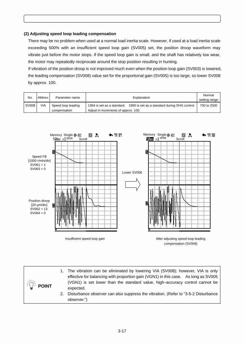
3-17
(2) Adjusting speed loop leading compensation There may be no problem when used at a normal load inertia scale. However, if used at a load inertia scale
exceeding 500% with an insufficient speed loop gain (SV005) set, the position droop waveform may
vibrate just before the motor stops. If the speed loop gain is small, and the shaft has relatively low wear,
the motor may repeatedly reciprocate around the stop position resulting in hunting.
If vibration of the position droop is not improved much even when the position loop gain (SV003) is lowered,
the leading compensation (SV008) value set for the proportional gain (SV005) is too large, so lower SV008
by approx. 100.
No. Abbrev. Parameter name Explanation Normal
setting range
SV008 VIA Speed loop leading compensation
1364 is set as a standard. 1900 is set as a standard during SHG control. Adjust in increments of approx. 100.
700 to 2500
POINT
1. The vibration can be eliminated by lowering VIA (SV008); however, VIA is only effective for balancing with proportion gain (VGN1) in this case. As long as SV005 (VGN1) is set lower than the standard value, high–accuracy control cannot be expected.
2. Disturbance observer can also suppress the vibration. (Refer to “3-5-2 Disturbance observer.”)
After adjusting speed loop leading compensation (SV008)
Insufficient speed loop gain
Memory Single shot Scroll
Memory Single shot Scroll
Position droop [20 µm/div]
SV062 = 13 SV064 = 0
Speed FB [1000 r/min/div]
SV061 = 1 SV063 = 0
Lower SV008
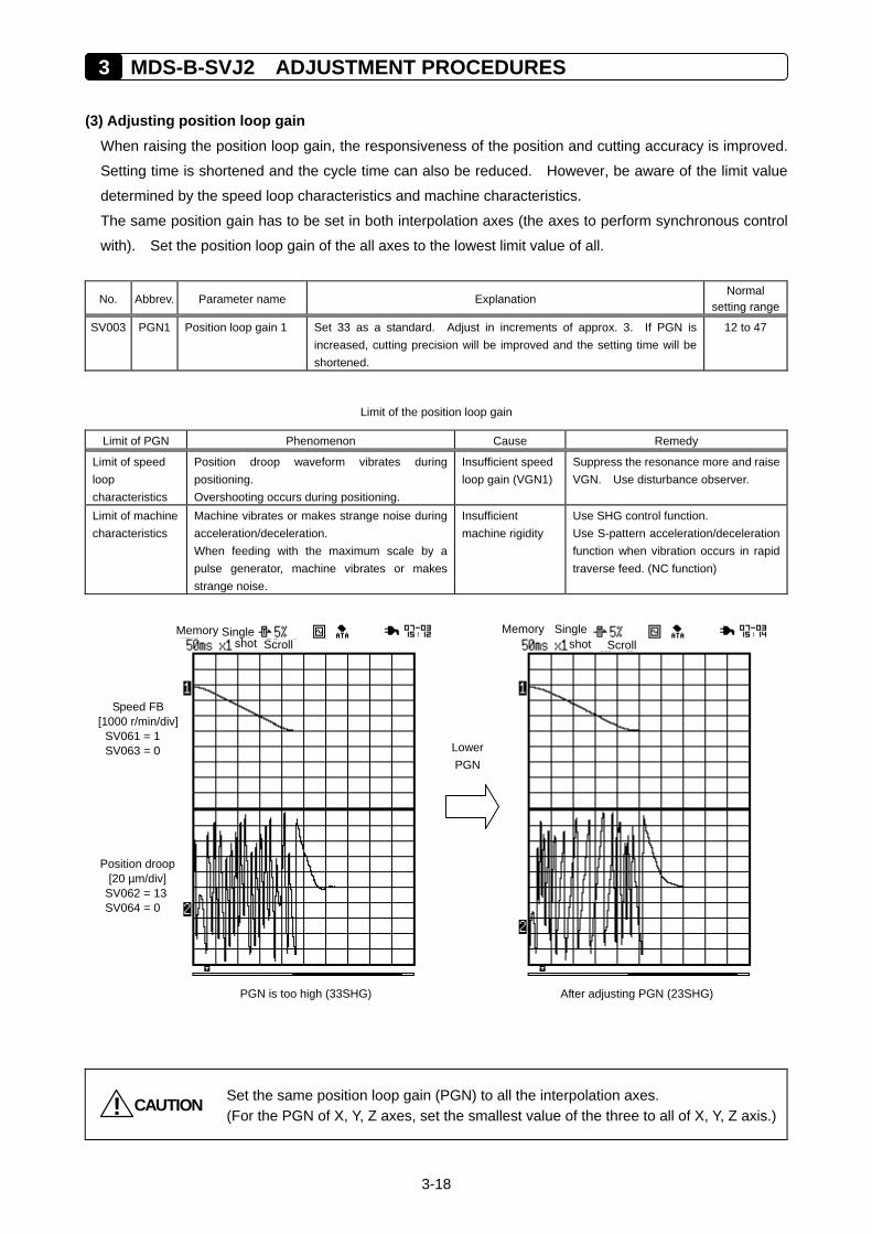
3 MDS-B-SVJ2 ADJUSTMENT PROCEDURES
3-18
(3) Adjusting position loop gain When raising the position loop gain, the responsiveness of the position and cutting accuracy is improved.
Setting time is shortened and the cycle time can also be reduced. However, be aware of the limit value
determined by the speed loop characteristics and machine characteristics.
The same position gain has to be set in both interpolation axes (the axes to perform synchronous control
with). Set the position loop gain of the all axes to the lowest limit value of all.
No. Abbrev. Parameter name Explanation Normal
setting range
SV003 PGN1 Position loop gain 1 Set 33 as a standard. Adjust in increments of approx. 3. If PGN is increased, cutting precision will be improved and the setting time will be shortened.
12 to 47
Limit of the position loop gain
Limit of PGN Phenomenon Cause Remedy
Limit of speed loop characteristics
Position droop waveform vibrates during positioning. Overshooting occurs during positioning.
Insufficient speed loop gain (VGN1)
Suppress the resonance more and raise VGN. Use disturbance observer.
Limit of machine characteristics
Machine vibrates or makes strange noise during acceleration/deceleration. When feeding with the maximum scale by a pulse generator, machine vibrates or makes strange noise.
Insufficient machine rigidity
Use SHG control function. Use S-pattern acceleration/deceleration function when vibration occurs in rapid traverse feed. (NC function)
CAUTION! Set the same position loop gain (PGN) to all the interpolation axes. (For the PGN of X, Y, Z axes, set the smallest value of the three to all of X, Y, Z axis.)
After adjusting PGN (23SHG) PGN is too high (33SHG)
Lower PGN
Memory Single shot Scroll
Memory Singleshot Scroll
Speed FB [1000 r/min/div]
SV061 = 1 SV063 = 0
Position droop [20 µm/div]
SV062 = 13 SV064 = 0
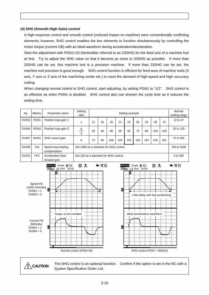
3-19
(4) SHG (Smooth High Gain) control A high-response control and smooth control (reduced impact on machine) were conventionally conflicting
elements; however, SHG control enables the two elements to function simultaneously by controlling the
motor torque (current GB) with an ideal waveform during acceleration/deceleration.
Start the adjustment with PGN1=23 (hereinafter referred to as 23SHG) for the feed axis of a machine tool
at first. Try to adjust the SHG value so that it become as close to 33SHG as possible. If more than
33SHG can be set, this machine tool is a precision machine. If more than 23SHG can be set, the
machine tool precision is good enough. SHG control function is efficient for feed axes of machine tools (X
axis, Y axis or Z axis of the machining center etc.) to meet the demand of high-speed and high–accuracy
cutting.
When changing normal control to SHG control, start adjusting, by setting PGN1 to “1/2”. SHG control is
as effective as when PGN1 is doubled. SHG control also can shorten the cycle time as it reduces the
setting time.
No. Abbrev. Parameter name Setting
ratio Setting example Normal
setting range
SV003 PGN1 Position loop gain 1
1 12 15 18 21 23 26 33 38 47 12 to 47
8 SV004 PGN2 Position loop gain 2
3
32 40 48 56 62 70 86 102 125
32 to 125
SV057 SHGC SHG control gain
6 72 90 108 126 140 160 187 225 281 72 to 281
SV008
VIA Speed loop leading compensation
Set 1900 as a standard for SHG control.
700 to 2500
SV015
FFC Acceleration feed forward gain
Set 100 as a standard for SHG control. 0 to 300
CAUTION! The SHG control is an optional function. Confirm if the option is set in the NC with a System Specification Order List.
SHG control (PGN = 26SHG) Normal control (PGN=26)
Ideal acceleration waveform Torque is not constant
Little delay with fast positioning
Speed FB [1000 r/min/div]
SV061 = 1 SV063 = 0
Current FB [50%/div]
SV062 = 2 SV064 = 0
Memory Singleshot Scroll
Memory Singleshot Scroll
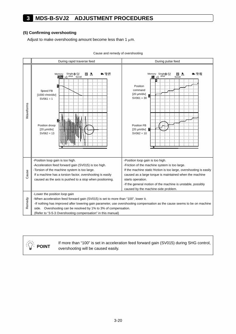
3 MDS-B-SVJ2 ADJUSTMENT PROCEDURES
3-20
(5) Confirming overshooting Adjust to make overshooting amount become less than 1 µm.
Cause and remedy of overshooting
During rapid traverse feed During pulse feed
Wav
efor
ms
Cau
se
-Position loop gain is too high. -Acceleration feed forward gain (SV015) is too high. -Torsion of the machine system is too large. If a machine has a torsion factor, overshooting is easily caused as the axis is pushed to a stop when positioning.
-Position loop gain is too high. -Friction of the machine system is too large. If the machine static friction is too large, overshooting is easily caused as a large torque is maintained when the machine starts operation. -If the general motion of the machine is unstable, possibly caused by the machine-side problem.
Rem
edy
-Lower the position loop gain -When acceleration feed forward gain (SV015) is set to more than “100”, lower it. -If nothing has improved after lowering gain parameter, use overshooting compensation as the cause seems to be on machine side. Overshooting can be resolved by 1% to 3% of compensation. (Refer to “3-5-3 Overshooting compensation” in this manual)
POINT
If more than “100” is set in acceleration feed forward gain (SV015) during SHG control, overshooting will be caused easily.
Memory Single
shot Scroll
Position droop [20 µm/div] SV062 = 13
Speed FB [1000 r/min/div]
SV061 = 1
Memory Single
shot Scroll
Position FB[20 µm/div]SV062 = 10
Position command [20 µm/div]SV061 = 30
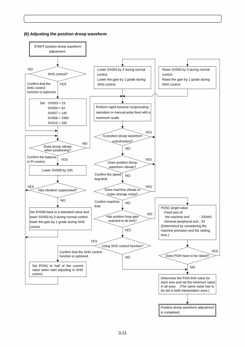
3-21
(6) Adjusting the position droop waveform
PGN1 target value -Feed axis of the machine tool : 33SHG-General peripheral axis : 33
(Determined by considering the machine precision and the setting time.)
Confirm that the SHG control function is optioned.
Position droop waveform adjustment is completed.
Lower SV008 by 100.
Set SV003 = 23 SV004 = 62 SV057 = 140 SV008 = 1900 SV015 = 100
Does position droop waveform vibrate?
Has vibration suppressed?
Is position droop waveform overshooting?
Lower SV003 by 3 during normal control. Lower the gain by 1 grade during SHG control.
Using SHG control function?
Does PGN have to be raised?
Does machine vibrate or make strange noise?
Has position loop gain reached to its limit?
Perform rapid traverse reciprocating operation or manual pulse feed with amaximum scale.
Raise SV003 by 3 during normal control. Raise the gain by 1 grade during SHG control.
Determine the PGN limit value for each axis and set the minimum value in all axes. (The same value has to be set in both interpolation axes.)
SHG control?
START position droop waveform adjustment.
Does droop vibrate when positioning?
YES
NO
YES
NO
Confirm the balance in PI control.
YES
NO
Set SV008 back to a standard value and; lower SV003 by 3 during normal control. lower the gain by 1 grade during SHG control.
YES
NO
NO
YES
Confirm the speed loop limit.
YES
NOConfirm machine limit.
YES
NO
Confirm that the SHG control function is optioned.
Set PGN1 to half of the currentvalue when start adjusting in SHGcontrol.
YES
YES
NO
NO
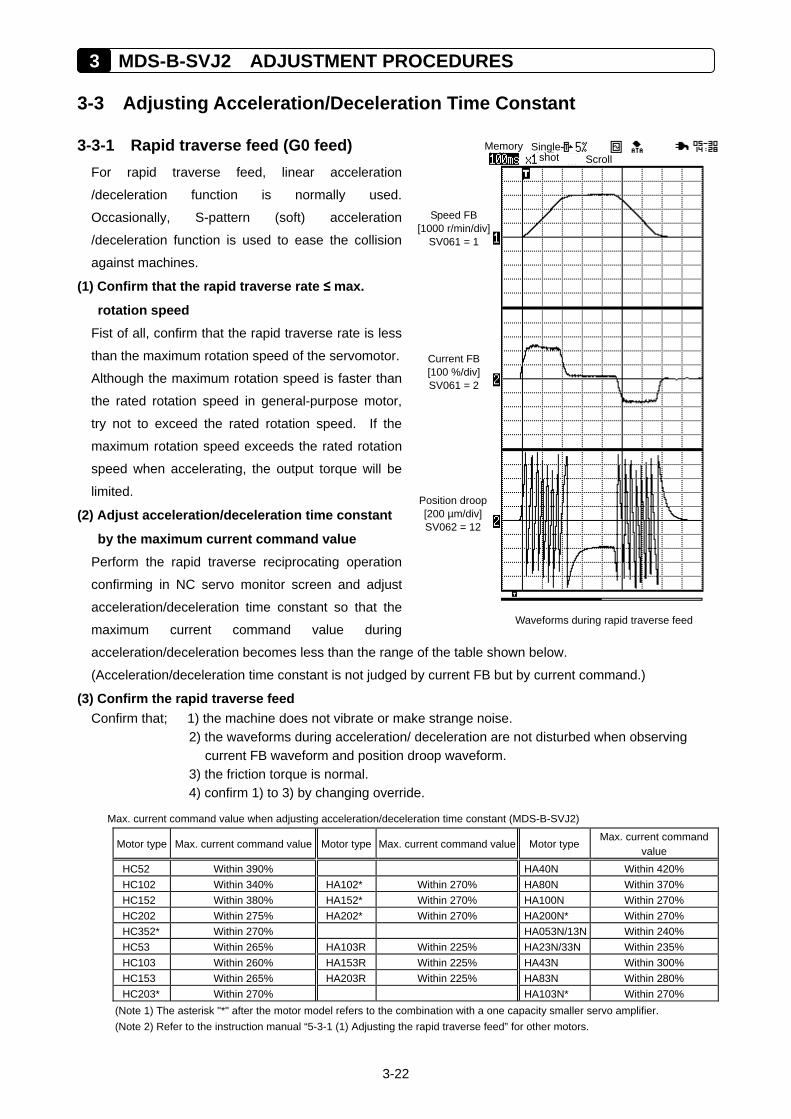
3 MDS-B-SVJ2 ADJUSTMENT PROCEDURES
3-22
3-3 Adjusting Acceleration/Deceleration Time Constant
3-3-1 Rapid traverse feed (G0 feed) For rapid traverse feed, linear acceleration
/deceleration function is normally used.
Occasionally, S-pattern (soft) acceleration
/deceleration function is used to ease the collision
against machines.
(1) Confirm that the rapid traverse rate ≤ max.
rotation speed Fist of all, confirm that the rapid traverse rate is less
than the maximum rotation speed of the servomotor.
Although the maximum rotation speed is faster than
the rated rotation speed in general-purpose motor,
try not to exceed the rated rotation speed. If the
maximum rotation speed exceeds the rated rotation
speed when accelerating, the output torque will be
limited.
(2) Adjust acceleration/deceleration time constant
by the maximum current command value Perform the rapid traverse reciprocating operation
confirming in NC servo monitor screen and adjust
acceleration/deceleration time constant so that the
maximum current command value during
acceleration/deceleration becomes less than the range of the table shown below.
(Acceleration/deceleration time constant is not judged by current FB but by current command.)
(3) Confirm the rapid traverse feed Confirm that; 1) the machine does not vibrate or make strange noise.
2) the waveforms during acceleration/ deceleration are not disturbed when observing current FB waveform and position droop waveform.
3) the friction torque is normal. 4) confirm 1) to 3) by changing override.
Max. current command value when adjusting acceleration/deceleration time constant (MDS-B-SVJ2)
Motor type Max. current command value Motor type Max. current command value Motor type Max. current command
value HC52 Within 390% HA40N Within 420% HC102 Within 340% HA102* Within 270% HA80N Within 370% HC152 Within 380% HA152* Within 270% HA100N Within 270% HC202 Within 275% HA202* Within 270% HA200N* Within 270% HC352* Within 270% HA053N/13N Within 240% HC53 Within 265% HA103R Within 225% HA23N/33N Within 235% HC103 Within 260% HA153R Within 225% HA43N Within 300% HC153 Within 265% HA203R Within 225% HA83N Within 280% HC203* Within 270% HA103N* Within 270%
(Note 1) The asterisk "*" after the motor model refers to the combination with a one capacity smaller servo amplifier. (Note 2) Refer to the instruction manual “5-3-1 (1) Adjusting the rapid traverse feed” for other motors.
Memory Single shot Scroll
Waveforms during rapid traverse feed
Position droop[200 µm/div]SV062 = 12
Speed FB [1000 r/min/div]
SV061 = 1
Current FB [100 %/div] SV061 = 2
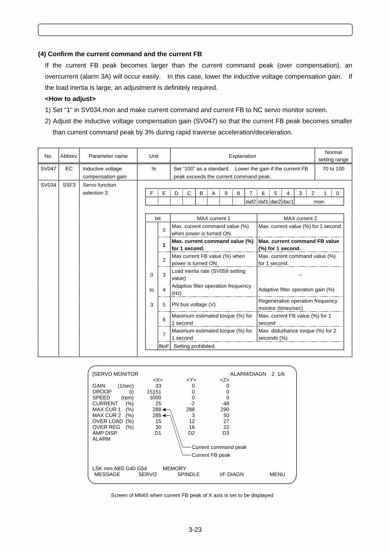
3-23
(4) Confirm the current command and the current FB If the current FB peak becomes larger than the current command peak (over compensation), an
overcurrent (alarm 3A) will occur easily. In this case, lower the inductive voltage compensation gain. If
the load inertia is large, an adjustment is definitely required.
<How to adjust> 1) Set “1” in SV034.mon and make current command and current FB to NC servo monitor screen.
2) Adjust the inductive voltage compensation gain (SV047) so that the current FB peak becomes smaller
than current command peak by 3% during rapid traverse acceleration/deceleration.
No. Abbrev. Parameter name Unit Explanation Normal
setting range
SV047
EC Inductive voltage compensation gain
% Set “100” as a standard. Lower the gain if the current FB peak exceeds the current command peak.
70 to 100
SV034 SSF3 F E D C B A 9 8 7 6 5 4 3 2 1 0 daf2 daf1 dac2 dac1 mon bit MAX current 1 MAX current 2
0Max. current command value (%) when power is turned ON.
Max. current value (%) for 1 second.
1Max. current command value (%) for 1 second.
Max. current command FB value (%) for 1 second.
2Max current FB value (%) when power is turned ON.
Max. current command value (%) for 1 second.
0 3Load inertia rate (SV059 setting value)
–
to 4Adaptive filter operation frequency (Hz)
Adaptive filter operation gain (%)
3 5 PN bus voltage (V) Regenerative operation frequency monitor (times/sec)
6Maximum estimated torque (%) for 1 second
Max. current FB value (%) for 1 second
7Maximum estimated torque (%) for 1 second
Max. disturbance torque (%) for 2 seconds (%)
8toF Setting prohibited.
Servo function selection 3
[SERVO MONITOR ALARM/DIAGN 2. 1/6 <X> <Y> <Z>
GAIN (1/sec) 33 0 0 DROOP (i) 15151 0 0 SPEED (rpm) 3000 0 0 CURRENT (%) 25 -2 -48 MAX CUR 1 (%) 288 288 290 MAX CUR 2 (%) 285 3 50 OVER LOAD (%) 15 12 27 OVER REG (%) 30 16 22 AMP DISP D1 D2 D3 ALARM LSK mm ABS G40 G54 MEMORY MESSAGE SERVO SPINDLE I/F DIAGN MENU
Screen of M64S when current FB peak of X axis is set to be displayed
Current FB peak Current command peak
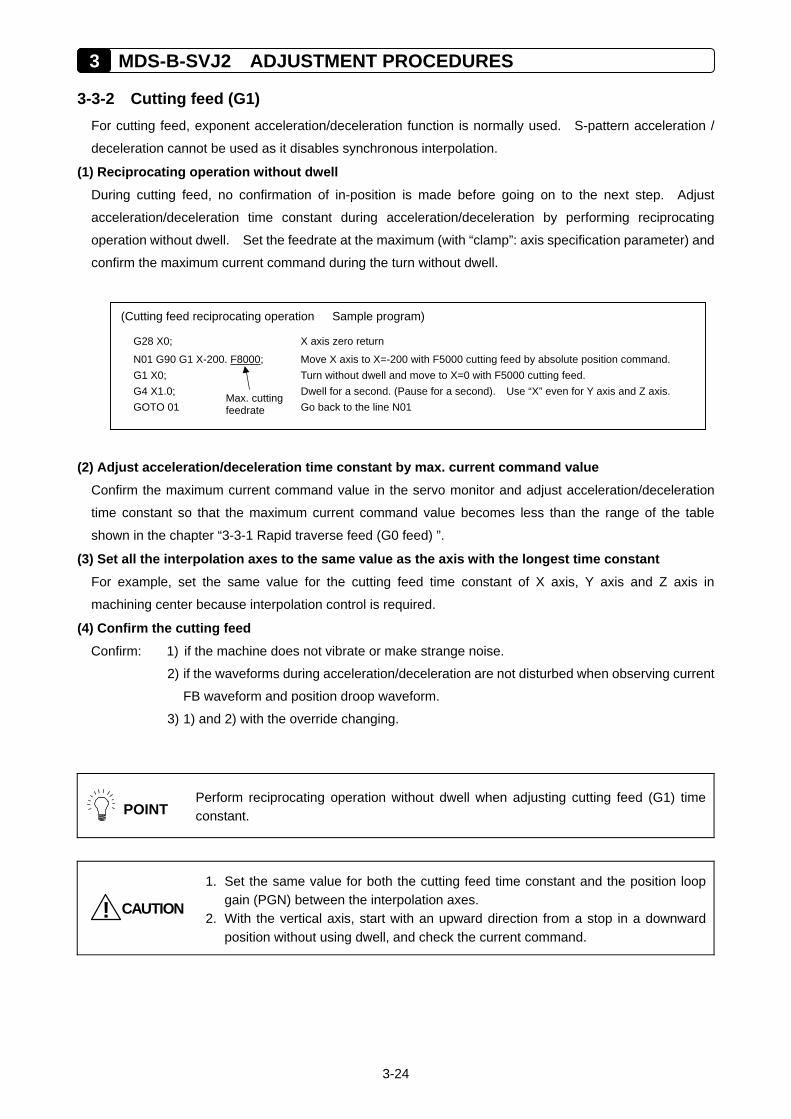
3 MDS-B-SVJ2 ADJUSTMENT PROCEDURES
3-24
3-3-2 Cutting feed (G1) For cutting feed, exponent acceleration/deceleration function is normally used. S-pattern acceleration /
deceleration cannot be used as it disables synchronous interpolation.
(1) Reciprocating operation without dwell During cutting feed, no confirmation of in-position is made before going on to the next step. Adjust
acceleration/deceleration time constant during acceleration/deceleration by performing reciprocating
operation without dwell. Set the feedrate at the maximum (with “clamp”: axis specification parameter) and
confirm the maximum current command during the turn without dwell.
(2) Adjust acceleration/deceleration time constant by max. current command value Confirm the maximum current command value in the servo monitor and adjust acceleration/deceleration
time constant so that the maximum current command value becomes less than the range of the table
shown in the chapter “3-3-1 Rapid traverse feed (G0 feed) ”.
(3) Set all the interpolation axes to the same value as the axis with the longest time constant For example, set the same value for the cutting feed time constant of X axis, Y axis and Z axis in
machining center because interpolation control is required.
(4) Confirm the cutting feed Confirm: 1) if the machine does not vibrate or make strange noise.
2) if the waveforms during acceleration/deceleration are not disturbed when observing current
FB waveform and position droop waveform.
3) 1) and 2) with the override changing.
POINT
Perform reciprocating operation without dwell when adjusting cutting feed (G1) time constant.
CAUTION!
1. Set the same value for both the cutting feed time constant and the position loop gain (PGN) between the interpolation axes.
2. With the vertical axis, start with an upward direction from a stop in a downward position without using dwell, and check the current command.
(Cutting feed reciprocating operation Sample program)
G28 X0; X axis zero return
N01 G90 G1 X-200. F8000; Move X axis to X=-200 with F5000 cutting feed by absolute position command. G1 X0; Turn without dwell and move to X=0 with F5000 cutting feed. G4 X1.0; Dwell for a second. (Pause for a second). Use “X” even for Y axis and Z axis. GOTO 01 Go back to the line N01
Max. cutting feedrate
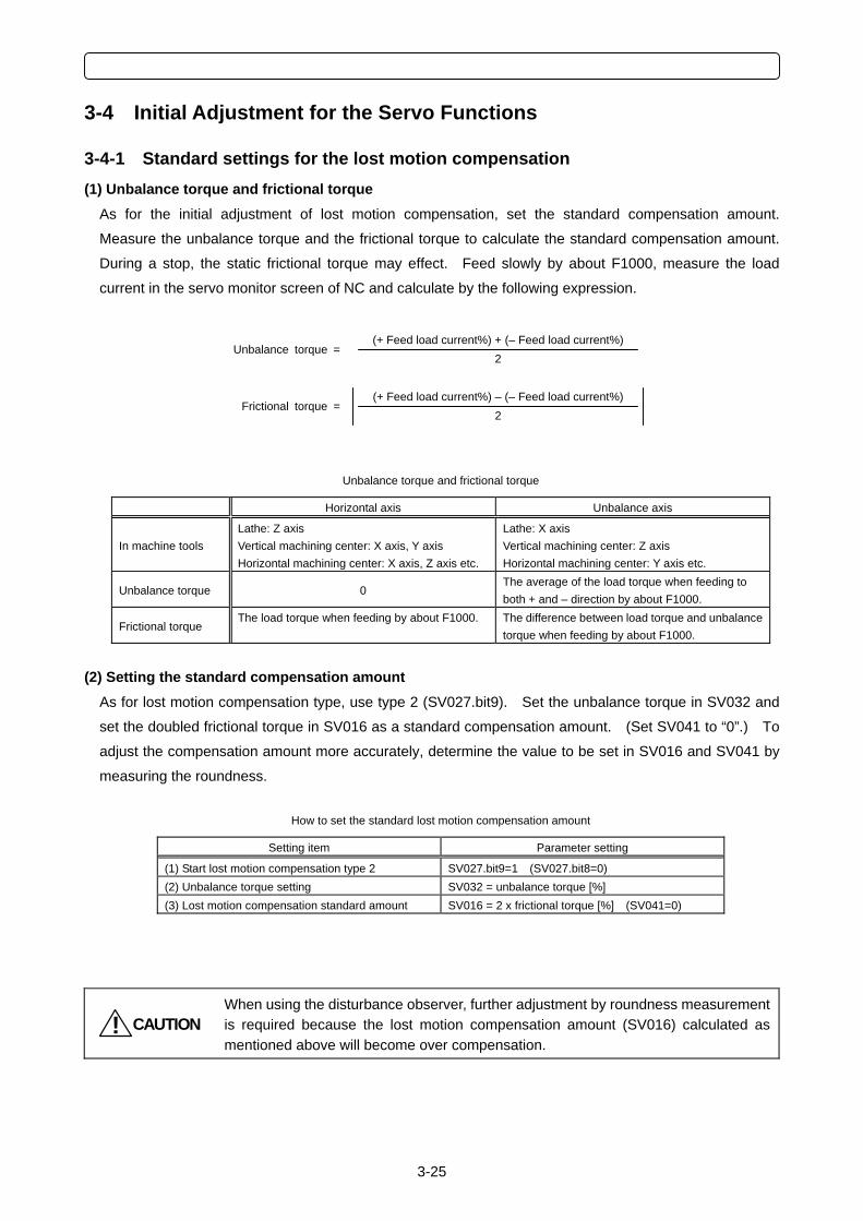
3-25
3-4 Initial Adjustment for the Servo Functions
3-4-1 Standard settings for the lost motion compensation (1) Unbalance torque and frictional torque
As for the initial adjustment of lost motion compensation, set the standard compensation amount.
Measure the unbalance torque and the frictional torque to calculate the standard compensation amount.
During a stop, the static frictional torque may effect. Feed slowly by about F1000, measure the load
current in the servo monitor screen of NC and calculate by the following expression.
Unbalance torque and frictional torque
Horizontal axis Unbalance axis
In machine tools Lathe: Z axis Vertical machining center: X axis, Y axis Horizontal machining center: X axis, Z axis etc.
Lathe: X axis Vertical machining center: Z axis Horizontal machining center: Y axis etc.
Unbalance torque 0 The average of the load torque when feeding to both + and – direction by about F1000.
Frictional torque The load torque when feeding by about F1000. The difference between load torque and unbalance
torque when feeding by about F1000.
(2) Setting the standard compensation amount As for lost motion compensation type, use type 2 (SV027.bit9). Set the unbalance torque in SV032 and
set the doubled frictional torque in SV016 as a standard compensation amount. (Set SV041 to “0”.) To
adjust the compensation amount more accurately, determine the value to be set in SV016 and SV041 by
measuring the roundness.
How to set the standard lost motion compensation amount
Setting item Parameter setting
(1) Start lost motion compensation type 2 SV027.bit9=1 (SV027.bit8=0) (2) Unbalance torque setting SV032 = unbalance torque [%] (3) Lost motion compensation standard amount SV016 = 2 x frictional torque [%] (SV041=0)
CAUTION!
When using the disturbance observer, further adjustment by roundness measurement is required because the lost motion compensation amount (SV016) calculated as mentioned above will become over compensation.
2(+ Feed load current%) + (– Feed load current%)
Unbalance torque =
2(+ Feed load current%) – (– Feed load current%)
Frictional torque =
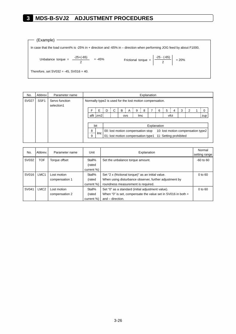
3 MDS-B-SVJ2 ADJUSTMENT PROCEDURES
3-26
(Example)
In case that the load current% is -25% in + direction and -65% in – direction when performing JOG feed by about F1000, Therefore, set SV032 = -45, SV016 = 40.
No. Abbrev Parameter name Explanation
SV027 SSF1 Servo function Normally type2 is used for the lost motion compensation. selection1 F E D C B A 9 8 7 6 5 4 3 2 1 0 aflt zrn2 ovs lmc vfct zup bit Explanation 8 00: lost motion compensation stop 10: lost motion compensation type2 9
lmc01: lost motion compensation type1 11: Setting prohibited
No. Abbrev. Parameter name Unit Explanation Normal
setting range
SV032
TOF Torque offset Stall% (rated
current %)
Set the unbalance torque amount. -60 to 60
SV016 LMC1 Lost motion compensation 1
Stall% (rated
current %)
Set “2 x (frictional torque)” as an initial value. When using disturbance observer, further adjustment by roundness measurement is required.
0 to 60
SV041 LMC2 Lost motion compensation 2
Stall% (rated
current %)
Set “0” as a standard (initial adjustment value). When “0” is set, compensate the value set in SV016 in both + and – direction.
0 to 60
-25+(-65) 2
= -45% Unbalance torque = -25 - (-65)
2 = 20% Frictional torque =
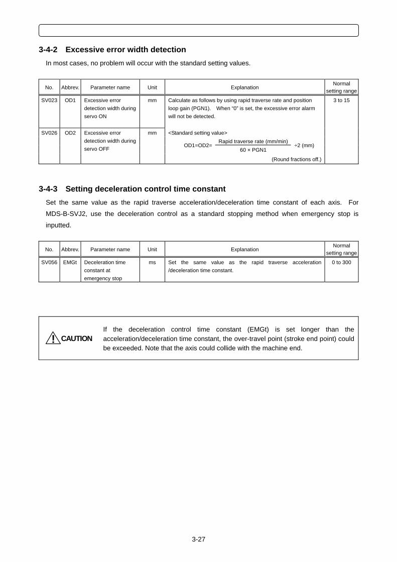
3-27
3-4-2 Excessive error width detection In most cases, no problem will occur with the standard setting values.
No. Abbrev. Parameter name Unit Explanation Normal
setting range
SV023
OD1 Excessive error detection width during servo ON
mm Calculate as follows by using rapid traverse rate and position loop gain (PGN1). When “0” is set, the excessive error alarm will not be detected. <Standard setting value>
Rapid traverse rate (mm/min) OD1=OD2=
60 × PGN1 ÷2 (mm)
SV026
OD2 Excessive error detection width during servo OFF
mm
(Round fractions off.)
3 to 15
3-4-3 Setting deceleration control time constant Set the same value as the rapid traverse acceleration/deceleration time constant of each axis. For
MDS-B-SVJ2, use the deceleration control as a standard stopping method when emergency stop is
inputted.
No. Abbrev. Parameter name Unit Explanation Normal
setting range
SV056
EMGt Deceleration time constant at emergency stop
ms Set the same value as the rapid traverse acceleration /deceleration time constant.
0 to 300
CAUTION!
If the deceleration control time constant (EMGt) is set longer than the acceleration/deceleration time constant, the over-travel point (stroke end point) could be exceeded. Note that the axis could collide with the machine end.
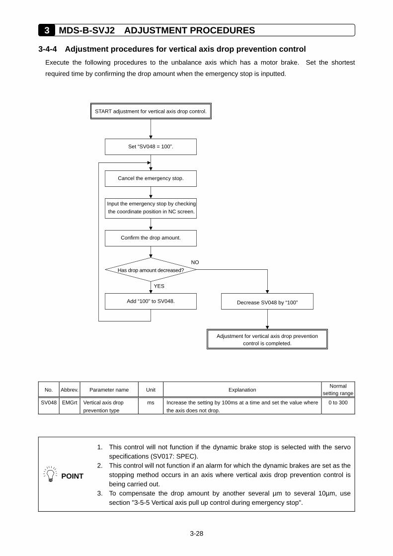
3 MDS-B-SVJ2 ADJUSTMENT PROCEDURES
3-28
3-4-4 Adjustment procedures for vertical axis drop prevention control Execute the following procedures to the unbalance axis which has a motor brake. Set the shortest
required time by confirming the drop amount when the emergency stop is inputted.
No. Abbrev. Parameter name Unit Explanation Normal
setting range
SV048
EMGrt Vertical axis drop prevention type
ms Increase the setting by 100ms at a time and set the value where the axis does not drop.
0 to 300
POINT
1. This control will not function if the dynamic brake stop is selected with the servo specifications (SV017: SPEC).
2. This control will not function if an alarm for which the dynamic brakes are set as the stopping method occurs in an axis where vertical axis drop prevention control is being carried out.
3. To compensate the drop amount by another several µm to several 10µm, use section "3-5-5 Vertical axis pull up control during emergency stop".
START adjustment for vertical axis drop control.
Has drop amount decreased? NO
Input the emergency stop by checkingthe coordinate position in NC screen.
YES
Cancel the emergency stop.
Confirm the drop amount.
Add “100” to SV048. Decrease SV048 by “100”
Adjustment for vertical axis drop prevention control is completed.
Set “SV048 = 100”.
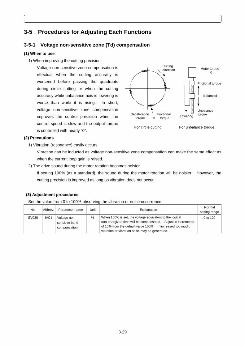
3-29
3-5 Procedures for Adjusting Each Functions
3-5-1 Voltage non-sensitive zone (Td) compensation (1) When to use
1) When improving the cutting precision
Voltage non-sensitive zone compensation is
effectual when the cutting accuracy is
worsened before passing the quadrants
during circle cutting or when the cutting
accuracy while unbalance axis is lowering is
worse than while it is rising. In short,
voltage non-sensitive zone compensation
improves the control precision when the
control speed is slow and the output torque
is controlled with nearly “0”.
(2) Precautions 1) Vibration (resonance) easily occurs
Vibration can be inducted as voltage non-sensitive zone compensation can make the same effect as
when the current loop gain is raised.
2) The drive sound during the motor rotation becomes noisier
If setting 100% (as a standard), the sound during the motor rotation will be noisier. However, the
cutting precision is improved as long as vibration does not occur.
(3) Adjustment procedures Set the value from 0 to 100% observing the vibration or noise occurrence.
No. Abbrev. Parameter name Unit Explanation Normal
setting range
SV030 IVC1 Voltage non- sensitive band compensation
% When 100% is set, the voltage equivalent to the logical non-energized time will be compensated. Adjust in increments of 10% from the default value 100%. If increased too much, vibration or vibration noise may be generated.
0 to 100
Motor torque = 0
Frictional torque
Balanced
Unbalance torque
For unbalance torque For circle cutting
Cutting direction
Deceleration Frictional torque = torque Lowering
3 MDS-B-SVJ2 ADJUSTMENT PROCEDURES
3-30
3-5-2 Disturbance observer function (1) When to use
1) When improving cutting precision
Disturbance observer function is efficient to improve the cutting accuracy. For roundness
measurement, cutting accuracy can be improved especially at around 45 degrees.
2) When suppressing the vibration of position droop waveform
Disturbance observer function can suppress the vibration of position droop waveform caused by the
insufficient speed loop gain (VGN) without lowering the speed loop leading compensation (VIA).
3) When suppressing the collision sound during lost motion compensation
When the lost motion compensation amount is increased, the collision sound is occasionally caused.
The compensation amount can be made smaller by using disturbance observer function, and it also
suppresses the collision sound.
(2) Other precautions 1) Vibration (resonance) is easily caused
Disturbance observer is hardly used for some machine characteristics.
2) Lost motion compensation has to be adjusted again
When changing observer filter pole (SV043) and gain (SV044), the optimal lost motion amount
(SV016, SV041) is also changed.
CAUTION! When starting disturbance observer, lost motion compensation has to be adjusted again.
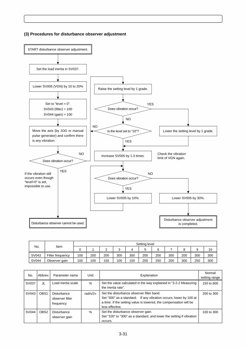
3-31
(3) Procedures for disturbance observer adjustment
Setting level
No. Item 0 1 2 3 4 5 6 7 8 9 10
SV043 Filter frequency 100 200 200 300 300 200 200 300 200 300 300SV044 Observer gain 100 100 150 100 150 200 250 200 300 250 300
No. Abbrev. Parameter name Unit Explanation Normal
setting range
SV037
JL Load inertia scale % Set the value calculated in the way explained in “3-2-2 Measuring the inertia rate”.
150 to 600
SV043
OBS1 Disturbance observer filter frequency
rad/s/2π Set the disturbance observer filter band. Set “300” as a standard. If any vibration occurs, lower by 100 at a time. If the setting value is lowered, the compensation will be less effective.
200 to 300
SV044
OBS2 Disturbance observer gain
% Set the disturbance observer gain. Set “100” to “300” as a standard, and lower the setting if vibration occurs.
100 to 300
START disturbance observer adjustment.
Does vibration occur?
Lower SV005 (VGN) by 10 to 20%
YES
Move the axis (by JOG or manualpulse generator) and confirm thereis any vibration.
Set to “level = 0”. SV043 (filter) = 100 SV044 (gain) = 100
Disturbance observer cannot be used.
Set the load inertia in SV037.
NO
Disturbance observer adjustment is completed.
Raise the setting level by 1 grade.
Does vibration occur?
Is the level set to “10”? NO
YES
NO
YES
Lower the setting level by 1 grade.
Increase SV005 by 1.3 times.
Does vibration occur?
Lower SV005 by 10%.
YES
NO
Lower SV005 by 30%.
Check the vibration limit of VGN again.
If the vibration still occurs even though “level=0” is set, impossible to use.
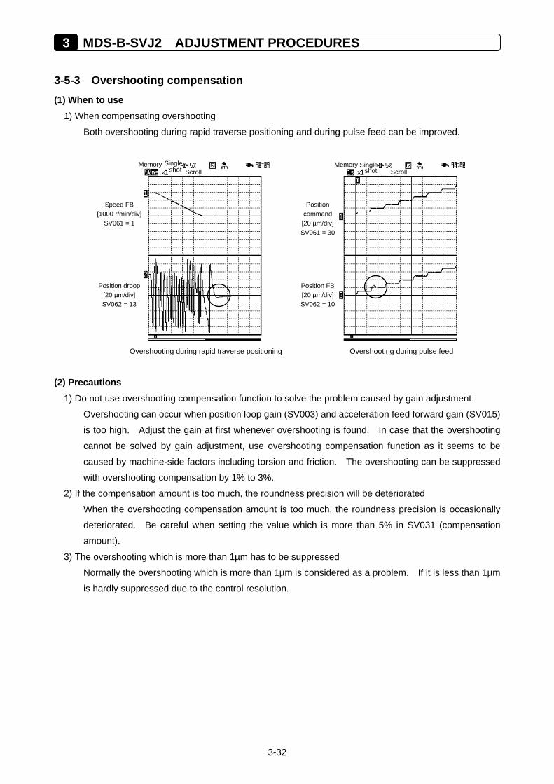
3 MDS-B-SVJ2 ADJUSTMENT PROCEDURES
3-32
3-5-3 Overshooting compensation (1) When to use
1) When compensating overshooting
Both overshooting during rapid traverse positioning and during pulse feed can be improved.
Overshooting during rapid traverse positioning Overshooting during pulse feed
(2) Precautions 1) Do not use overshooting compensation function to solve the problem caused by gain adjustment
Overshooting can occur when position loop gain (SV003) and acceleration feed forward gain (SV015)
is too high. Adjust the gain at first whenever overshooting is found. In case that the overshooting
cannot be solved by gain adjustment, use overshooting compensation function as it seems to be
caused by machine-side factors including torsion and friction. The overshooting can be suppressed
with overshooting compensation by 1% to 3%.
2) If the compensation amount is too much, the roundness precision will be deteriorated
When the overshooting compensation amount is too much, the roundness precision is occasionally
deteriorated. Be careful when setting the value which is more than 5% in SV031 (compensation
amount).
3) The overshooting which is more than 1µm has to be suppressed
Normally the overshooting which is more than 1µm is considered as a problem. If it is less than 1µm
is hardly suppressed due to the control resolution.
Memory Single shot Scroll
Position droop [20 µm/div] SV062 = 13
Speed FB [1000 r/min/div]
SV061 = 1
Memory Single
shot Scroll
Position FB[20 µm/div]SV062 = 10
Position command [20 µm/div]SV061 = 30
3-33
(3) Details of overshooting compensation method 1) Overshooting compensation type 1
This is compatible with the standard specifications. The offset amount is set based on the motor’s stall
current. Determine the amount that is free from overshoot by adjusting the compensation gain
(SV031, SV042) while increasing its value in increments of 1%. This adjustment is usually made
within the range from 1% to 3%.
Compensation will not be performed if the next feed command has been issued before the motor
completes positioning (before position droop becomes “0”). Therefore, no compensation will be
performed during circle cutting, and this prevents the precision of the roundness from being
deteriorated. Also, compensation will not be performed in the high-speed high-accuracy control (the
feed forward control) mode.
2) Overshooting compensation type 2 (Equivalent to the type 3 of MDS-C1-Vx)
This is used when overshooting compensation is required even during the feed forward control (the
high-speed high-accuracy control). During the feed forward control (the high-speed high-accuracy
control), an overshoot may be occurred due to inappropriate adjustment of the feed forward gain. So,
when adjusting the compensation gain (SV031, SV042), stop the feed forward control, or set “fwd_g”
to “0”. If overshoot occurs in the feed forward control mode only (no overshoot occurs in the normal
control mode), adjust the feed forward gain (fwd_g).
POINT
When using overshooting compensation type 1, 1. Compensation will not be performed if the next feed command has been issued
before the motor completes positioning (or stops). (Therefore, no compensation will be performed during circle cutting.)
2. Compensation is not made when performing the feed forward control (the high-speed high-accuracy control).
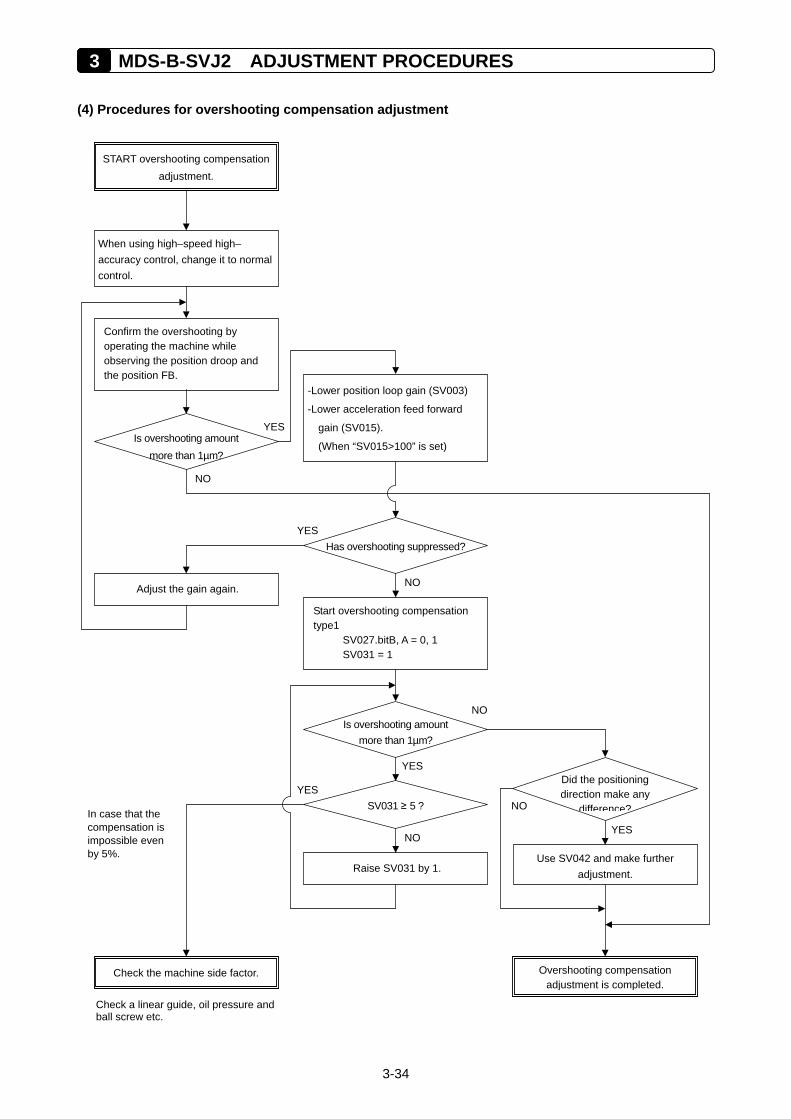
3 MDS-B-SVJ2 ADJUSTMENT PROCEDURES
3-34
(4) Procedures for overshooting compensation adjustment
Has overshooting suppressed?
START overshooting compensation adjustment.
SV031 ≥ 5 ?
When using high–speed high– accuracy control, change it to normal control.
YES
Confirm the overshooting by operating the machine while observing the position droop and the position FB.
YES
Overshooting compensation adjustment is completed.
Is overshooting amount more than 1µm?
In case that the compensation is impossible even by 5%.
-Lower position loop gain (SV003)
-Lower acceleration feed forward
gain (SV015).
(When “SV015>100” is set)
Adjust the gain again. NO
Start overshooting compensation type1
SV027.bitB, A = 0, 1 SV031 = 1
Is overshooting amount more than 1µm?
Raise SV031 by 1.
YES
NO
NO
Check the machine side factor.
YES
NO
Did the positioning direction make any
difference?
YES
Use SV042 and make further adjustment.
NO
Check a linear guide, oil pressure and ball screw etc.
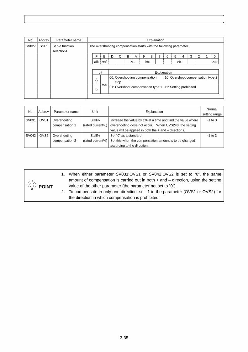
3-35
No. Abbrev Parameter name Explanation
SV027 SSF1 The overshooting compensation starts with the following parameter.
Servo function selection1
F E D C B A 9 8 7 6 5 4 3 2 1 0 aflt zrn2 ovs lmc vfct zup bit Explanation
A 00: Overshooting compensation
stop 10: Overshoot compensation type 2
B ovs
01: Overshoot compensation type 1 11: Setting prohibited
No. Abbrev. Parameter name Unit Explanation Normal
setting range
SV031 OVS1 Overshooting compensation 1
Stall% (rated current%)
Increase the value by 1% at a time and find the value where overshooting dose not occur. When OVS2=0, the setting value will be applied in both the + and – directions.
-1 to 3
SV042 OVS2 Overshooting compensation 2
Stall% (rated current%)
Set “0” as a standard. Set this when the compensation amount is to be changed according to the direction.
-1 to 3
POINT
1. When either parameter SV031:OVS1 or SV042:OVS2 is set to “0”, the same amount of compensation is carried out in both + and – direction, using the setting value of the other parameter (the parameter not set to “0”).
2. To compensate in only one direction, set -1 in the parameter (OVS1 or OVS2) for the direction in which compensation is prohibited.
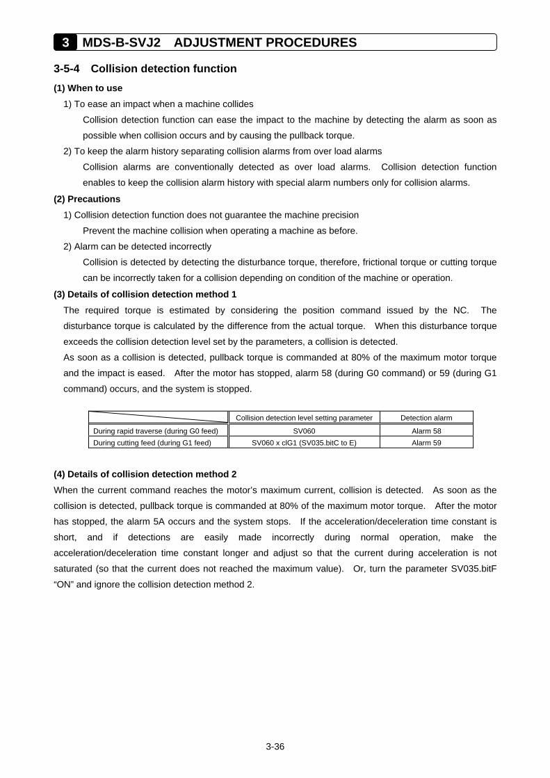
3 MDS-B-SVJ2 ADJUSTMENT PROCEDURES
3-36
3-5-4 Collision detection function (1) When to use
1) To ease an impact when a machine collides
Collision detection function can ease the impact to the machine by detecting the alarm as soon as
possible when collision occurs and by causing the pullback torque.
2) To keep the alarm history separating collision alarms from over load alarms
Collision alarms are conventionally detected as over load alarms. Collision detection function
enables to keep the collision alarm history with special alarm numbers only for collision alarms.
(2) Precautions 1) Collision detection function does not guarantee the machine precision
Prevent the machine collision when operating a machine as before.
2) Alarm can be detected incorrectly
Collision is detected by detecting the disturbance torque, therefore, frictional torque or cutting torque
can be incorrectly taken for a collision depending on condition of the machine or operation.
(3) Details of collision detection method 1 The required torque is estimated by considering the position command issued by the NC. The
disturbance torque is calculated by the difference from the actual torque. When this disturbance torque
exceeds the collision detection level set by the parameters, a collision is detected.
As soon as a collision is detected, pullback torque is commanded at 80% of the maximum motor torque
and the impact is eased. After the motor has stopped, alarm 58 (during G0 command) or 59 (during G1
command) occurs, and the system is stopped.
Collision detection level setting parameter Detection alarm
During rapid traverse (during G0 feed) SV060 Alarm 58 During cutting feed (during G1 feed) SV060 x clG1 (SV035.bitC to E) Alarm 59
(4) Details of collision detection method 2 When the current command reaches the motor’s maximum current, collision is detected. As soon as the
collision is detected, pullback torque is commanded at 80% of the maximum motor torque. After the motor
has stopped, the alarm 5A occurs and the system stops. If the acceleration/deceleration time constant is
short, and if detections are easily made incorrectly during normal operation, make the
acceleration/deceleration time constant longer and adjust so that the current during acceleration is not
saturated (so that the current does not reached the maximum value). Or, turn the parameter SV035.bitF
“ON” and ignore the collision detection method 2.
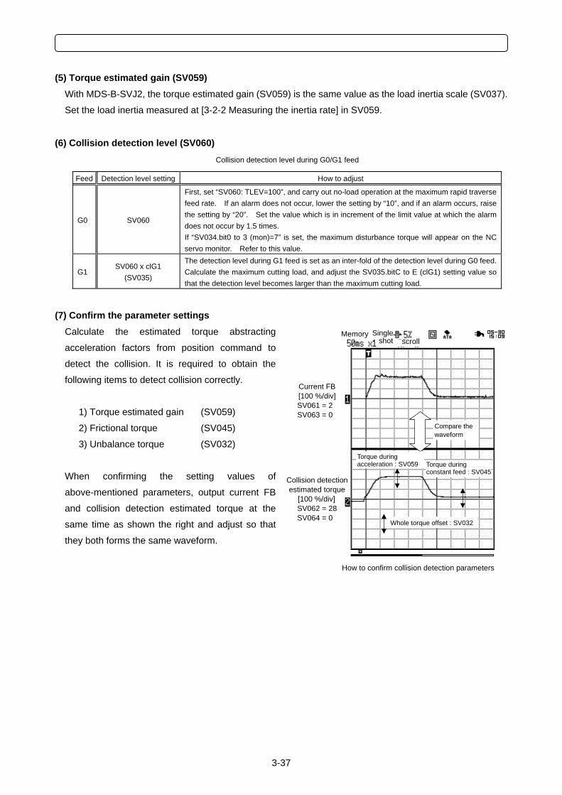
3-37
(5) Torque estimated gain (SV059) With MDS-B-SVJ2, the torque estimated gain (SV059) is the same value as the load inertia scale (SV037).
Set the load inertia measured at [3-2-2 Measuring the inertia rate] in SV059.
(6) Collision detection level (SV060) Collision detection level during G0/G1 feed
Feed Detection level setting How to adjust
G0 SV060
First, set “SV060: TLEV=100”, and carry out no-load operation at the maximum rapid traverse feed rate. If an alarm does not occur, lower the setting by “10”, and if an alarm occurs, raise the setting by “20”. Set the value which is in increment of the limit value at which the alarm does not occur by 1.5 times. If “SV034.bit0 to 3 (mon)=7” is set, the maximum disturbance torque will appear on the NC servo monitor. Refer to this value.
G1 SV060 x clG1
(SV035)
The detection level during G1 feed is set as an inter-fold of the detection level during G0 feed. Calculate the maximum cutting load, and adjust the SV035.bitC to E (clG1) setting value so that the detection level becomes larger than the maximum cutting load.
(7) Confirm the parameter settings Calculate the estimated torque abstracting
acceleration factors from position command to
detect the collision. It is required to obtain the
following items to detect collision correctly.
1) Torque estimated gain (SV059)
2) Frictional torque (SV045)
3) Unbalance torque (SV032)
When confirming the setting values of
above-mentioned parameters, output current FB
and collision detection estimated torque at the
same time as shown the right and adjust so that
they both forms the same waveform.
Memory Single shot scroll
How to confirm collision detection parameters
Collision detection estimated torque
[100 %/div] SV062 = 28 SV064 = 0
Current FB [100 %/div] SV061 = 2 SV063 = 0
Whole torque offset : SV032
Torque during acceleration : SV059
Compare the waveform
Torque during constant feed : SV045
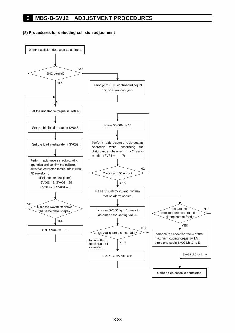
3 MDS-B-SVJ2 ADJUSTMENT PROCEDURES
3-38
(8) Procedures for detecting collision adjustment
START collision detection adjustment.
SHG control?
Change to SHG control and adjustthe position loop gain.
Collision detection is completed.
YES
NO
Set the unbalance torque in SV032.
Set the frictional torque in SV045.
Set the load inertia rate in SV059.
Perform rapid traverse reciprocating operation and confirm the collision detection estimated torque and currentFB waveform.
(Refer to the next page.) SV061 = 2, SV062 = 28 SV063 = 0, SV064 = 0
Does the waveform showsthe same wave shape?
NO
YES
Lower SV060 by 10.
Perform rapid traverse reciprocatingoperation while confirming thedisturbance observer in NC servomonitor (SV34 = 7)
Does alarm 58 occur?
Set “SV060 = 100”.
NO
Raise SV060 by 20 and confirm that no alarm occurs.
YES
Increase SV060 by 1.5 times to determine the setting value.
Do you ignore the method 2?
Set “SV035.bitF = 1”
YES
NO
In case that acceleration is saturated.
Increase the specified value of the maximum cutting torque by 1.5 times and set in SV035.bitC to E.
Do you use collision detection function
during cutting feed?
YES
NO
SV035.bitC to E = 0
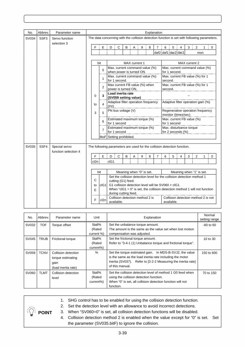
3-39
No. Abbrev. Parameter name Explanation
SV034 SSF3 The data concerning with the collision detection function is set with following parameters.
F E D C B A 9 8 7 6 5 4 3 2 1 0 daf2 daf1 dac2 dac1 mon bit MAX current 1 MAX current 2
0Max. current command value (%) when power is turned ON.
Max. current command value (%) for 1 second.
1Max. current command value (%) for 1 second.
Max. current FB value (%) for 1 second.
2Max current FB value (%) when power is turned ON.
Max. current FB value (%) for 1 second.
0 3Load inertia rate (SV059 setting value) –
to 4Adaptive filter operation frequency (Hz)
Adaptive filter operation gain (%)
3 5PN bus voltage (V) Regenerative operation frequency
monitor (times/sec)
6Estimated maximum torque (%) for 1 second
Max. current FB value (%) for 1 second
7Estimated maximum torque (%) for 1 second
Max. disturbance torque for 2 seconds (%)
8toF Setting prohibited.
Servo function selection 3
SV035 SSF4 The following parameters are used for the collision detection function.
F E D C B A 9 8 7 6 5 4 3 2 1 0 cl2n clG1 bit Meaning when “0” is set. Meaning when “1” is set.
C to E
clG1
Set the collision detection level for the collision detection method 1 cutting (G1) feed. G1 collision detection level will be SV060 × clG1. When “clG1 = 0” is set, the collision detection method 1 will not function during cutting feed.
F cl2nCollision detection method 2 is available.
Collision detection method 2 is not available.
Special servo function selection 4
No. Abbrev. Parameter name Unit Explanation
Normal setting range
SV032 TOF Torque offset Stall% (Rated
current %)
Set the unbalance torque amount. The amount is the same as the value set when lost motion compensation was adjusted.
-60 to 60
SV045 TRUB Frictional torque Stall% (Rated
current%)
Set the frictional torque amount. Refer to “3-4-1 (1) Unbalance torque and frictional torque”.
10 to 30
SV059 TCNV Collision detection torque estimating gain (load inertia rate)
% Set the torque estimated gain. In MDS-B-SVJ2, the value is the same as the load inertia rate including the motor inertia (SV037). Refer to [3-2-2 Measuring the inertia rate] of this manual.
150 to 600
SV060 TLMT Collision detection level
Stall% (Rated
current%)
Set the collision detection level of method 1 G0 feed when using the collision detection function. When “0” is set, all collision detection function will not function.
70 to 150
POINT
1. SHG control has to be enabled for using the collision detection function. 2. Set the detection level with an allowance to avoid incorrect detections. 3. When “SV060=0” is set, all collision detection functions will be disabled. 4. Collision detection method 2 is enabled when the value except for “0” is set. Set
the parameter (SV035.bitF) to ignore the collision.
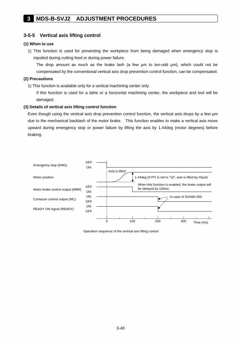
3 MDS-B-SVJ2 ADJUSTMENT PROCEDURES
3-40
3-5-5 Vertical axis lifting control (1) When to use
1) This function is used for preventing the workpiece from being damaged when emergency stop is
inputted during cutting feed or during power failure.
The drop amount as much as the brake lash (a few µm to ten-odd µm), which could not be
compensated by the conventional vertical axis drop prevention control function, can be compensated.
(2) Precautions 1) This function is available only for a vertical machining center only
If this function is used for a lathe or a horizontal machining center, the workpiece and tool will be
damaged.
(3) Details of vertical axis lifting control function Even though using the vertical axis drop prevention control function, the vertical axis drops by a few µm
due to the mechanical backlash of the motor brake. This function enables to make a vertical axis move
upward during emergency stop or power failure by lifting the axis by 1.44deg (motor degrees) before
braking.
Operation sequence of the vertical axis lifting control
OFF ON Emergency stop (EMG)
READY ON signal (READY)
0 100 200 300 Time (ms)
Motor brake control output (MBR)
Contactor control output (MC)
Motor position
Axis is lifted
1.44deg (If PIT is set to “10”, axis is lifted by 40µm)
When this function is enabled, the brake output willbe delayed by 100ms.
In case of SV048=200.
OFF ON ON OFF ON OFF
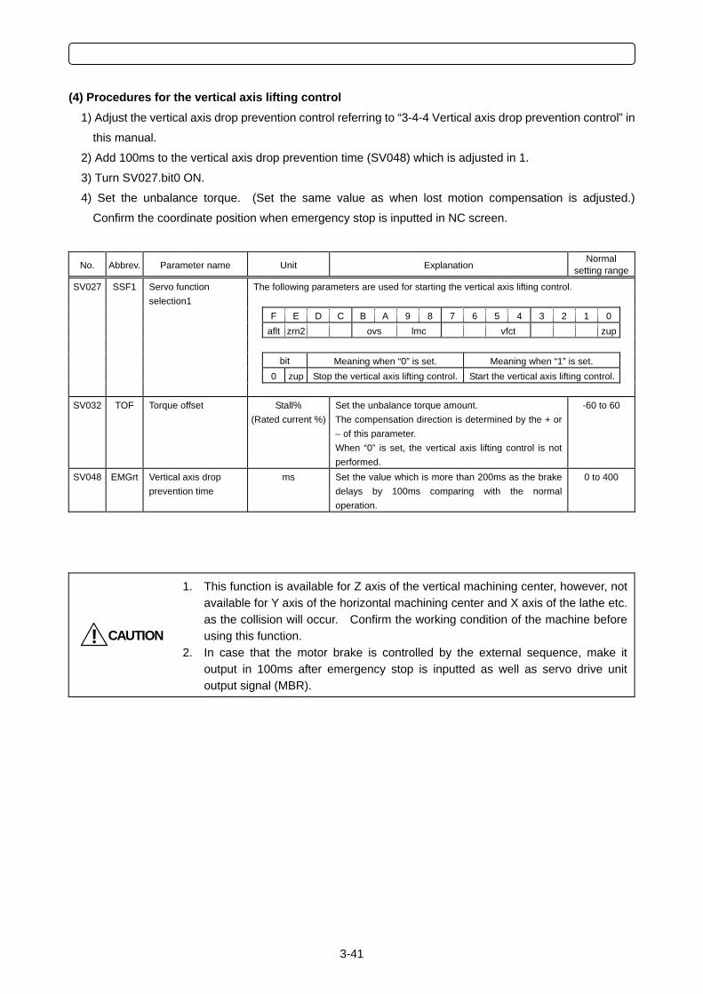
3-41
(4) Procedures for the vertical axis lifting control 1) Adjust the vertical axis drop prevention control referring to “3-4-4 Vertical axis drop prevention control” in
this manual.
2) Add 100ms to the vertical axis drop prevention time (SV048) which is adjusted in 1.
3) Turn SV027.bit0 ON.
4) Set the unbalance torque. (Set the same value as when lost motion compensation is adjusted.)
Confirm the coordinate position when emergency stop is inputted in NC screen.
No. Abbrev. Parameter name Unit Explanation Normal
setting range
SV027 SSF1 The following parameters are used for starting the vertical axis lifting control.
Servo function selection1
F E D C B A 9 8 7 6 5 4 3 2 1 0 aflt zrn2 ovs lmc vfct zup bit Meaning when “0” is set. Meaning when “1” is set. 0 zup Stop the vertical axis lifting control. Start the vertical axis lifting control.
SV032 TOF Torque offset Stall% (Rated current %)
Set the unbalance torque amount. The compensation direction is determined by the + or – of this parameter. When “0” is set, the vertical axis lifting control is not performed.
-60 to 60
SV048 EMGrt Vertical axis drop prevention time
ms Set the value which is more than 200ms as the brake delays by 100ms comparing with the normal operation.
0 to 400
CAUTION!
1. This function is available for Z axis of the vertical machining center, however, not available for Y axis of the horizontal machining center and X axis of the lathe etc. as the collision will occur. Confirm the working condition of the machine before using this function.
2. In case that the motor brake is controlled by the external sequence, make it output in 100ms after emergency stop is inputted as well as servo drive unit output signal (MBR).
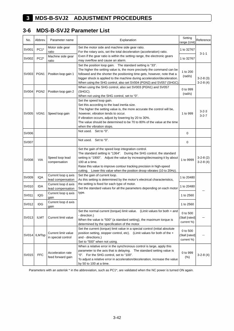
3 MDS-B-SVJ2 ADJUSTMENT PROCEDURES
3-42
3-6 MDS-B-SVJ2 Parameter List No. Abbrev. Parameter name Explanation
Setting range (Unit)
Reference
SV001 PC1* Motor side gear ratio
1 to 32767
SV002 PC2* Machine side gear ratio
Set the motor side and machine side gear ratio. For the rotary axis, set the total deceleration (acceleration) ratio. Even if the gear ratio is within the setting range, the electronic gears may overflow and cause an alarm. 1 to 32767
3-1-1
SV003 PGN1 Position loop gain 1
Set the position loop gain. The standard setting is “33”. The higher the setting value is, the more precisely the command can be followed and the shorter the positioning time gets, however, note that a bigger shock is applied to the machine during acceleration/deceleration. When using the SHG control, also set SV004 (PGN2) and SV057 (SHGC).
1 to 200 (rad/s)
SV004 PGN2 Position loop gain 2 When using the SHG control, also set SV003 (PGN1) and SV057 (SHGC). When not using the SHG control, set to “0”.
0 to 999 (rad/s)
3-2-8 (3)3-2-8 (4)
SV005 VGN1 Speed loop gain
Set the speed loop gain. Set this according to the load inertia size. The higher the setting value is, the more accurate the control will be, however, vibration tends to occur. If vibration occurs, adjust by lowering by 20 to 30%. The value should be determined to be 70 to 80% of the value at the time when the vibration stops.
1 to 999 3-2-3 3-2-7
SV006 Not used. Set to “0”.
0
SV007 Not used. Set to “0”.
0
SV008 VIA Speed loop lead compensation
Set the gain of the speed loop integration control. The standard setting is “1364”. During the SHG control, the standard setting is “1900”. Adjust the value by increasing/decreasing it by about 100 at a time. Raise this value to improve contour tracking precision in high-speed cutting. Lower this value when the position droop vibrates (10 to 20Hz).
1 to 99993-2-8 (2)3-2-8 (4)
SV009 IQA Current loop q axis lead compensation
1 to 20480
SV010 IDA Current loop d axis lead compensation
1 to 20480
SV011 IQG Current loop q axis gain
1 to 2560
SV012 IDG Current loop d axis gain
Set the gain of current loop. As this setting is determined by the motor’s electrical characteristics, the setting is fixed for each type of motor. Set the standard values for all the parameters depending on each motor type.
1 to 2560
–
SV013 ILMT Current limit value
Set the normal current (torque) limit value. (Limit values for both + and - direction.) When the value is “500” (a standard setting), the maximum torque is determined by the specification of the motor.
0 to 500 (Stall [rated]current %)
–
SV014 ILMTsp Current limit value in special control
Set the current (torque) limit value in a special control (initial absolute position setting, stopper control, etc). (Limit values for both of the + and - directions.) Set to “500” when not using.
0 to 500 (Stall [rated]current %)
–
SV015 FFC Acceleration rate feed forward gain
When a relative error in the synchronous control is large, apply this parameter to the axis that is delaying. The standard setting value is “0”. For the SHG control, set to “100”. To adjust a relative error in acceleration/deceleration, increase the value by 50 to 100 at a time.
0 to 999 (%)
3-2-8 (4)
Parameters with an asterisk * in the abbreviation, such as PC1*, are validated when the NC power is turned ON again.
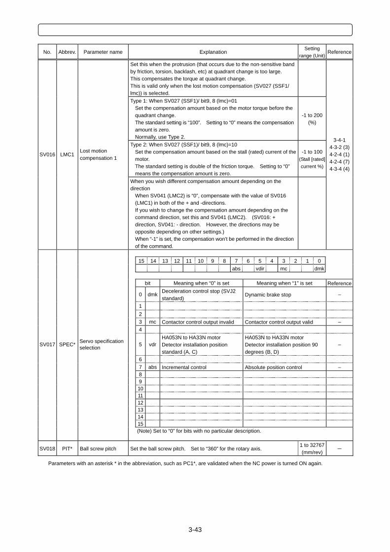
3-43
No. Abbrev. Parameter name Explanation
Setting range (Unit)
Reference
Set this when the protrusion (that occurs due to the non-sensitive band by friction, torsion, backlash, etc) at quadrant change is too large. This compensates the torque at quadrant change. This is valid only when the lost motion compensation (SV027 (SSF1/ lmc)) is selected.
Type 1: When SV027 (SSF1)/ bit9, 8 (lmc)=01 Set the compensation amount based on the motor torque before the quadrant change. The standard setting is “100”. Setting to “0” means the compensation amount is zero. Normally, use Type 2.
-1 to 200 (%)
Type 2: When SV027 (SSF1)/ bit9, 8 (lmc)=10 Set the compensation amount based on the stall (rated) current of the motor. The standard setting is double of the friction torque. Setting to “0” means the compensation amount is zero.
-1 to 100(Stall [rated] current %)
SV016 LMC1 Lost motion compensation 1
When you wish different compensation amount depending on the direction
When SV041 (LMC2) is “0”, compensate with the value of SV016 (LMC1) in both of the + and -directions. If you wish to change the compensation amount depending on the command direction, set this and SV041 (LMC2). (SV016: + direction, SV041: - direction. However, the directions may be opposite depending on other settings.) When “-1” is set, the compensation won’t be performed in the direction of the command.
3-4-1 4-3-2 (3)4-2-4 (1)4-2-4 (7)4-3-4 (4)
15 14 13 12 11 10 9 8 7 6 5 4 3 2 1 0
abs vdir mc dmk bit Meaning when “0” is set Meaning when “1” is set Reference
0 dmk Deceleration control stop (SVJ2 standard)
Dynamic brake stop –
1 2 3 mc Contactor control output invalid Contactor control output valid – 4
SV017 SPEC* Servo specification selection 5 vdr
HA053N to HA33N motor Detector installation position standard (A, C)
HA053N to HA33N motor Detector installation position 90 degrees (B, D)
–
6 7 abs Incremental control Absolute position control – 8 9 10 11 12 13 14 15
(Note) Set to “0” for bits with no particular description.
SV018 PIT* Ball screw pitch Set the ball screw pitch. Set to “360” for the rotary axis. 1 to 32767(mm/rev)
–
Parameters with an asterisk * in the abbreviation, such as PC1*, are validated when the NC power is turned ON again.
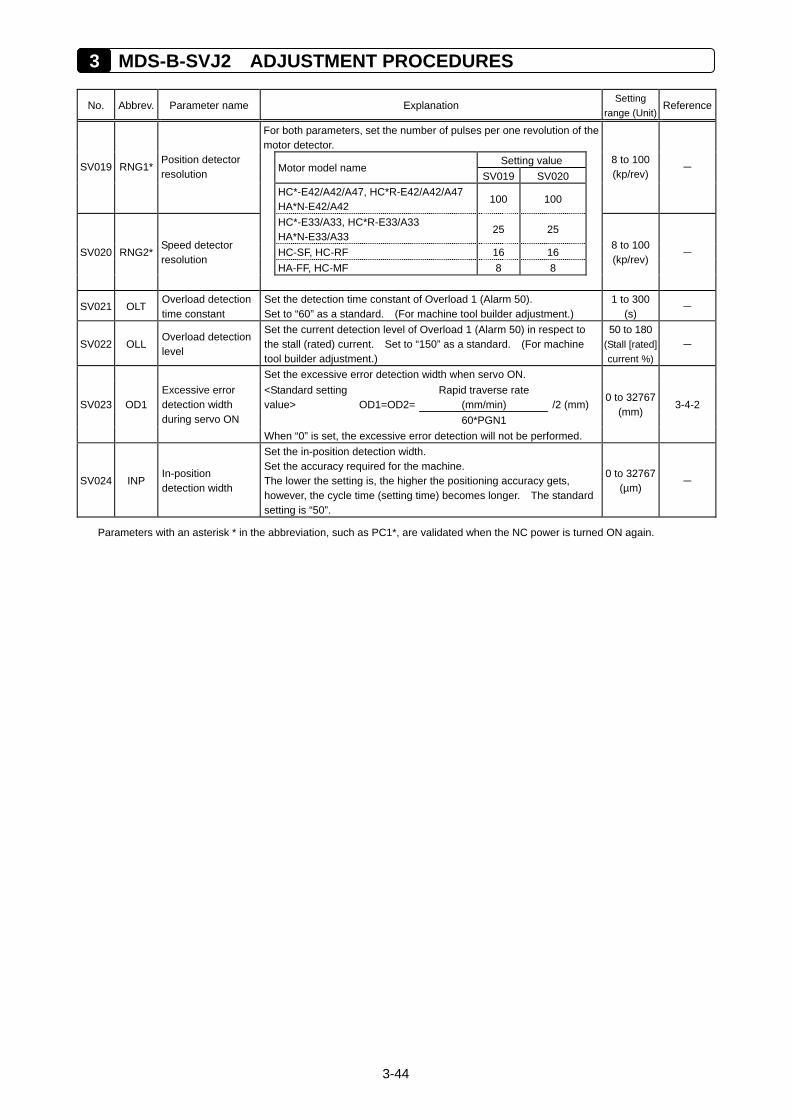
3 MDS-B-SVJ2 ADJUSTMENT PROCEDURES
3-44
No. Abbrev. Parameter name Explanation
Setting range (Unit)
Reference
For both parameters, set the number of pulses per one revolution of the motor detector. Setting value
Motor model name SV019 SV020
SV019 RNG1* Position detector resolution
HC*-E42/A42/A47, HC*R-E42/A42/A47 HA*N-E42/A42
100 100
8 to 100 (kp/rev)
–
HC*-E33/A33, HC*R-E33/A33 HA*N-E33/A33
25 25
HC-SF, HC-RF 16 16 HA-FF, HC-MF 8 8
SV020 RNG2* Speed detector resolution
8 to 100 (kp/rev)
–
SV021 OLT Overload detection time constant
Set the detection time constant of Overload 1 (Alarm 50). Set to “60” as a standard. (For machine tool builder adjustment.)
1 to 300 (s)
–
SV022 OLL Overload detection level
Set the current detection level of Overload 1 (Alarm 50) in respect to the stall (rated) current. Set to “150” as a standard. (For machine tool builder adjustment.)
50 to 180 (Stall [rated] current %)
–
Set the excessive error detection width when servo ON. Rapid traverse rate
(mm/min) <Standard setting value> OD1=OD2=
60*PGN1 /2 (mm)
0 to 32767(mm)
3-4-2 SV023 OD1 Excessive error detection width during servo ON
When “0” is set, the excessive error detection will not be performed.
SV024 INP In-position detection width
Set the in-position detection width. Set the accuracy required for the machine. The lower the setting is, the higher the positioning accuracy gets, however, the cycle time (setting time) becomes longer. The standard setting is “50”.
0 to 32767(µm)
–
Parameters with an asterisk * in the abbreviation, such as PC1*, are validated when the NC power is turned ON again.
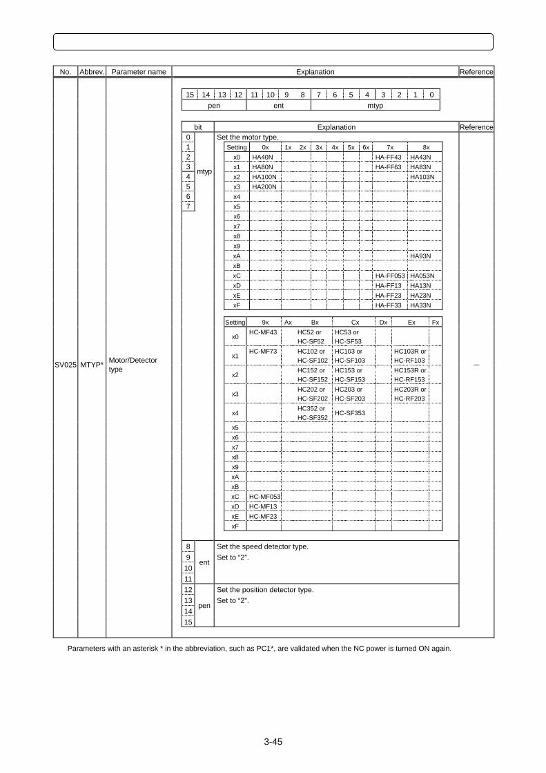
3-45
No. Abbrev. Parameter name Explanation Reference
15 14 13 12 11 10 9 8 7 6 5 4 3 2 1 0
pen ent mtyp
bit Explanation Reference 0 Set the motor type. 1 Setting 0x 1x 2x 3x 4x 5x 6x 7x 8x 2 x0 HA40N HA-FF43 HA43N 3 x1 HA80N HA-FF63 HA83N 4
mtyp x2 HA100N HA103N
5 x3 HA200N 6 x4 7 x5 x6 x7 x8 x9 xA HA93N xB xC HA-FF053 HA053N xD HA-FF13 HA13N xE HA-FF23 HA23N xF HA-FF33 HA33N Setting 9x Ax Bx Cx Dx Ex Fx
x0 HC-MF43
HC52 or HC-SF52
HC53 or HC-SF53
x1 HC-MF73
HC102 orHC-SF102
HC103 or HC-SF103
HC103R or HC-RF103
SV025 MTYP* Motor/Detector
type x2
HC152 orHC-SF152
HC153 or HC-SF153
HC153R or HC-RF153
–
x3 HC202 orHC-SF202
HC203 or HC-SF203
HC203R or HC-RF203
x4 HC352 orHC-SF352
HC-SF353
x5 x6 x7 x8 x9 xA xB xC HC-MF053 xD HC-MF13 xE HC-MF23 xF 8 Set the speed detector type. 9 Set to “2”. 10
ent
11 12 Set the position detector type. 13 Set to “2”. 14
pen
15
Parameters with an asterisk * in the abbreviation, such as PC1*, are validated when the NC power is turned ON again.
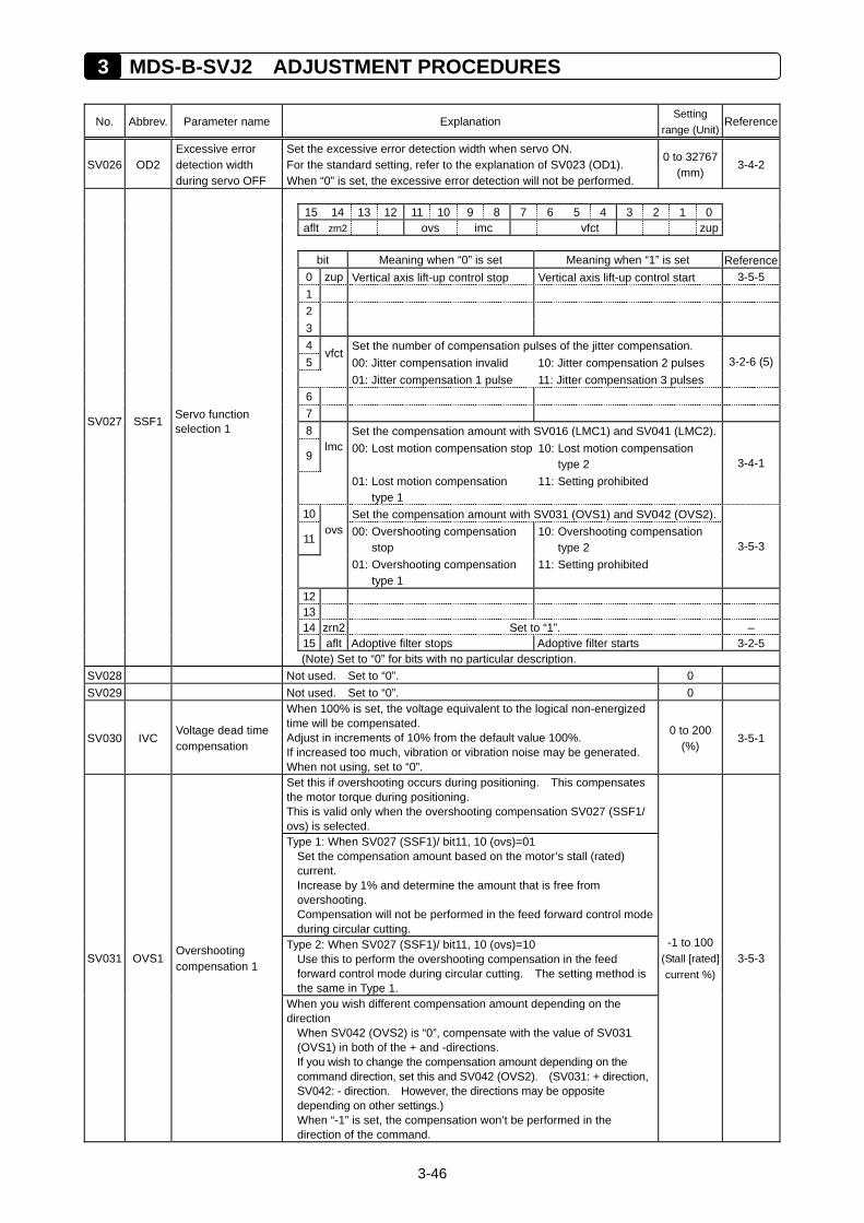
3 MDS-B-SVJ2 ADJUSTMENT PROCEDURES
3-46
No. Abbrev. Parameter name Explanation Setting
range (Unit)Reference
SV026 OD2 Excessive error detection width during servo OFF
Set the excessive error detection width when servo ON. For the standard setting, refer to the explanation of SV023 (OD1). When “0” is set, the excessive error detection will not be performed.
0 to 32767(mm)
3-4-2
15 14 13 12 11 10 9 8 7 6 5 4 3 2 1 0 aflt zrn2 ovs imc vfct zup
bit Meaning when “0” is set Meaning when “1” is set Reference 0 zup Vertical axis lift-up control stop Vertical axis lift-up control start 3-5-5 1 2 3 4 Set the number of compensation pulses of the jitter compensation. 5
vfct 00: Jitter compensation invalid 10: Jitter compensation 2 pulses
01: Jitter compensation 1 pulse 11: Jitter compensation 3 pulses 3-2-6 (5)
6 7
SV027 SSF1 Servo function selection 1 8 Set the compensation amount with SV016 (LMC1) and SV041 (LMC2).
9 lmc 00: Lost motion compensation stop
10: Lost motion compensation
type 2
01: Lost motion compensation type 1
11: Setting prohibited
3-4-1
10 Set the compensation amount with SV031 (OVS1) and SV042 (OVS2).
11 ovs 00: Overshooting compensation
stop 10: Overshooting compensation
type 2
01: Overshooting compensation type 1
11: Setting prohibited
3-5-3
12 13 14 zrn2 Set to “1”. – 15 aflt Adoptive filter stops Adoptive filter starts 3-2-5 (Note) Set to “0” for bits with no particular description.
SV028 Not used. Set to “0”. 0 SV029 Not used. Set to “0”. 0
SV030 IVC Voltage dead time compensation
When 100% is set, the voltage equivalent to the logical non-energized time will be compensated. Adjust in increments of 10% from the default value 100%. If increased too much, vibration or vibration noise may be generated. When not using, set to “0”.
0 to 200 (%)
3-5-1
Set this if overshooting occurs during positioning. This compensates the motor torque during positioning. This is valid only when the overshooting compensation SV027 (SSF1/ ovs) is selected. Type 1: When SV027 (SSF1)/ bit11, 10 (ovs)=01
Set the compensation amount based on the motor’s stall (rated) current. Increase by 1% and determine the amount that is free from overshooting. Compensation will not be performed in the feed forward control mode during circular cutting.
Type 2: When SV027 (SSF1)/ bit11, 10 (ovs)=10 Use this to perform the overshooting compensation in the feed forward control mode during circular cutting. The setting method is the same in Type 1.
SV031 OVS1 Overshooting compensation 1
When you wish different compensation amount depending on the direction
When SV042 (OVS2) is “0”, compensate with the value of SV031 (OVS1) in both of the + and -directions. If you wish to change the compensation amount depending on the command direction, set this and SV042 (OVS2). (SV031: + direction, SV042: - direction. However, the directions may be opposite depending on other settings.) When “-1” is set, the compensation won’t be performed in the direction of the command.
-1 to 100 (Stall [rated] current %)
3-5-3
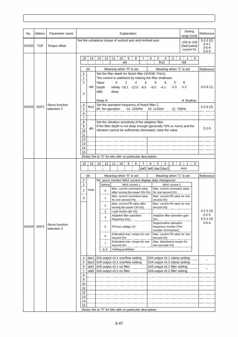
3-47
No. Abbrev. Parameter name Explanation Setting
range (Unit)Reference
SV032 TOF Torque offset
Set the unbalance torque of vertical axis and inclined axis. -100 to 100(Stall [rated] current %)
3-2-2 (2)3-4-1 3-5-4 3-5-5
15 14 13 12 11 10 9 8 7 6 5 4 3 2 1 0
afs fhz2 nfd
bit Meaning when “0” is set Meaning when “1” is set Reference 0 Set the filter depth for Notch filter (SV038: FHz1). 1 The control is stabilized by making the filter shallower. 2 Value 0 2 4 6 8 A C E
3
nfd Depth (dB) Deep
Infntlydeep
-18.1 -12.0 -8.5 -6.0 -4.1 -2.5 -1.2
Shallow
3-2-6 (1)
4 SV033 SSF2 Servo function selection 2 5
fhz2 Set the operation frequency of Notch filter 2. 00: No operation 01: 2250Hz 10: 1125Hz 11: 750Hz 3-2-6 (2)
6 7 8
9 10 11
afs
Set the vibration sensitivity of the adaptive filter. If the filter depth is not deep enough (generally 70% or more) and the vibration cannot be sufficiently eliminated, raise the value. 3-2-5
12 13 14 15 (Note) Set to “0” for bits with no particular description.
15 14 13 12 11 10 9 8 7 6 5 4 3 2 1 0 daf2 daf1 dac2 dac1 mon
bit Meaning when “0” is set Meaning when “1” is set Reference 0 NC servo monitor MAX current display data changeover 1 Setting MAX current 1 MAX current 2
2 0 Max. current command value after turning the power ON (%)
Max. current command value for one second (%)
3
mon
1 Max. current command value for one second (%)
Max. current FB value for one second (%)
2 Max. current FB value after turning the power ON (%)
Max. current FB value for one second (%)
3 Load inertia rate (%) -
4 Adaptive filter operation frequency (Hz)
Adaptive filter operation gain (%)
SV034 SSF3 Servo function selection 3 5 PN bus voltage (V)
Regenerative operation frequency monitor (The number of times/sec)
6 Estimated max. torque for one second (%)
Max. current FB value for one second (%)
7 Estimated max. torque for one second (%)
Max. disturbance torque for two seconds (%)
8~F Setting prohibited
3-2-2 (2)3-2-5
3-3-1 (4)3-5-4
4 dac1 D/A output ch.1 overflow setting D/A output ch.1 clamp setting 5 dac2 D/A output ch.2 overflow setting D/A output ch.2 clamp setting
–
6 daf1 D/A output ch.1 no filter D/A output ch.1 filter setting 7 daf2 D/A output ch.2 no filter D/A output ch.2 filter setting
–
8 9 10 11 12 13 14 15 (Note) Set to “0” for bits with no particular description.
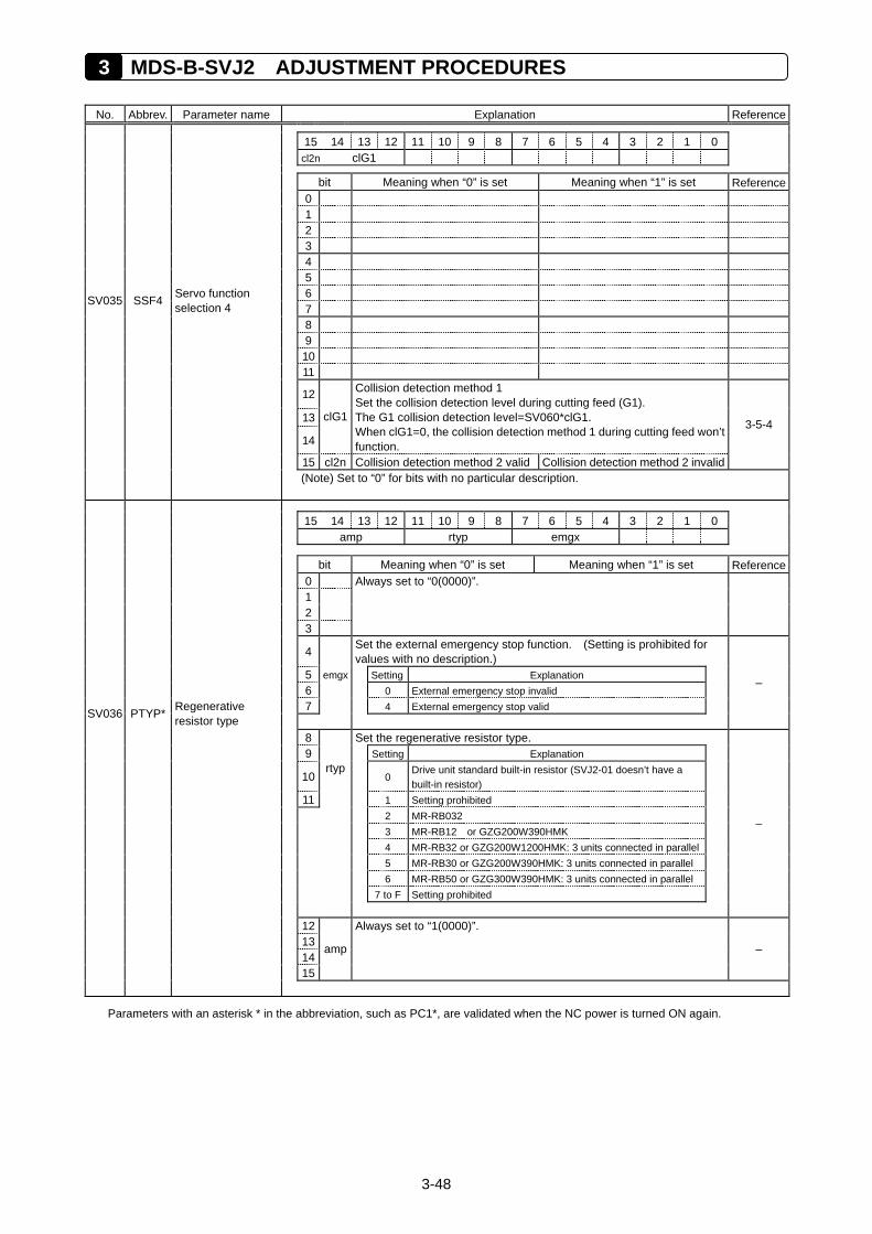
3 MDS-B-SVJ2 ADJUSTMENT PROCEDURES
3-48
No. Abbrev. Parameter name Explanation Reference
15 14 13 12 11 10 9 8 7 6 5 4 3 2 1 0 cl2n clG1
bit Meaning when “0” is set Meaning when “1” is set Reference 0 1 2 3 4 5
6 SV035 SSF4 Servo function selection 4 7
8 9 10 11
12
13
14
clG1
Collision detection method 1 Set the collision detection level during cutting feed (G1). The G1 collision detection level=SV060*clG1. When clG1=0, the collision detection method 1 during cutting feed won’t function.
15 cl2n Collision detection method 2 valid Collision detection method 2 invalid
3-5-4
(Note) Set to “0” for bits with no particular description.
15 14 13 12 11 10 9 8 7 6 5 4 3 2 1 0 amp rtyp emgx
bit Meaning when “0” is set Meaning when “1” is set Reference 0 1 2 3
Always set to “0(0000)”.
4 Set the external emergency stop function. (Setting is prohibited for values with no description.)
5 Setting Explanation 6 0 External emergency stop invalid
7
emgx
4 External emergency stop valid SV036 PTYP* Regenerative resistor type
–
8 Set the regenerative resistor type. 9 Setting Explanation
10 0 Drive unit standard built-in resistor (SVJ2-01 doesn’t have a built-in resistor)
11
rtyp
1 Setting prohibited 2 MR-RB032 3 MR-RB12 or GZG200W390HMK 4 MR-RB32 or GZG200W1200HMK: 3 units connected in parallel 5 MR-RB30 or GZG200W390HMK: 3 units connected in parallel 6 MR-RB50 or GZG300W390HMK: 3 units connected in parallel 7 to F Setting prohibited
–
12 13 14 15
amp
Always set to “1(0000)”.
–
Parameters with an asterisk * in the abbreviation, such as PC1*, are validated when the NC power is turned ON again.
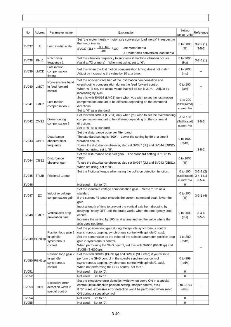
3-49
No. Abbrev. Parameter name Explanation Setting
range (Unit)Reference
Set “the motor inertia + motor axis conversion load inertia” in respect to the motor inertia.
SV037 JL Load inertia scale SV037 (JL) = Jl + Jm
Jm *100 Jm: Motor inertia Jl : Motor axis conversion load inertia
0 to 5000(%)
3-2-2 (1)3-5-2
SV038 FHz1 Notch filter frequency 1
Set the vibration frequency to suppress if machine vibration occurs. (Valid at 72 or more) When not using, set to “0”.
0 to 3000(Hz)
3-2-6 (1)
SV039 LMCD Lost motion compensation timing
Set this when the lost motion compensation timing doest not match. Adjust by increasing the value by 10 at a time.
0 to 2000(ms)
–
SV040 LMCT Non-sensitive band in feed forward control
Set the non-sensitive bad of the lost motion compensation and overshooting compensation during the feed forward control. When “0” is set, the actual value that will be set is 2µm. Adjust by increasing by 1µm.
0 to 100 (µm)
–
SV041 LMC2 Lost motion compensation 2
Set this with SV016 (LMC1) only when you wish to set the lost motion compensation amount to be different depending on the command directions. Set to “0” as a standard.
-1 to 200(Stall [rated] current %)
–
SV042 OVS2 Overshooting compensation 2
Set this with SV031 (OVS1) only when you wish to set the overshooting compensation amount to be different depending on the command directions. Set to “0” as a standard.
-1 to 100(Stall [rated] current %)
3-5-3
SV043 OBS1 Disturbance observer filter frequency
Set the disturbance observer filter band. The standard setting is “300”. Lower the setting by 50 at a time if vibration occurs. To use the disturbance observer, also set SV037 (JL) and SV044 (OBS2). When not using, set to “0”.
0 to 1000(rad/s)
SV044 OBS2 Disturbance observer gain
Set the disturbance observer gain. The standard setting is “100” to “300”. To use the disturbance observer, also set SV037 (JL) and SV043 (OBS1). When not using, set to “0”.
0 to 1000(%)
3-5-2
SV045 TRUB Frictional torque Set the frictional torque when using the collision detection function. 0 to 100
(Stall [rated] current %)
3-2-2 (2)3-4-1 (1)
3-5-4 SV046 Not used. Set to “0”. 0
SV047 EC Inductive voltage compensation gain
Set the inductive voltage compensation gain. Set to “100” as a standard. If the current FB peak exceeds the current command peak, lower the gain.
0 to 200 (%)
3-3-1 (4)
SV048 EMGrt Vertical axis drop prevention time
Input a length of time to prevent the vertical axis from dropping by delaying Ready OFF until the brake works when the emergency stop occurs. Increase the setting by 100ms at a time and set the value where the axis does not drop.
0 to 2000(ms)
3-4-4 3-5-5
SV049 PGN1sp
Position loop gain 1 in spindle synchronous control
Set the position loop gain during the spindle synchronous control (synchronous tapping, synchronous control with spindle/C axis). Set the same value as the value of the spindle parameter, position loop gain in synchronous control. When performing the SHG control, set this with SV050 (PGN2sp) and SV058 (SHGCsp).
1 to 200 (rad/s)
SV050 PGN2sp
Position loop gain 2 in spindle synchronous control
Set this with SV049 (PGN1sp) and SV058 (SHGCsp) if you wish to perform the SHG control in the spindle synchronous control (synchronous tapping, synchronous control with spindle/C axis). When not performing the SHG control, set to “0”.
0 to 999 (rad/s)
–
SV051 Not used. Set to “0”. 0 SV052 Not used. Set to “0”. 0
SV053 OD3 Excessive error detection width in special control
Set the excessive error detection width when servo ON in a special control (initial absolute position setting, stopper control, etc.). If “0” is set, excessive error detection won’t be performed when servo ON during a special control.
0 to 32767(mm)
–
SV054 Not used. Set to “0”. 0 SV055 Not used. Set to “0”. 0
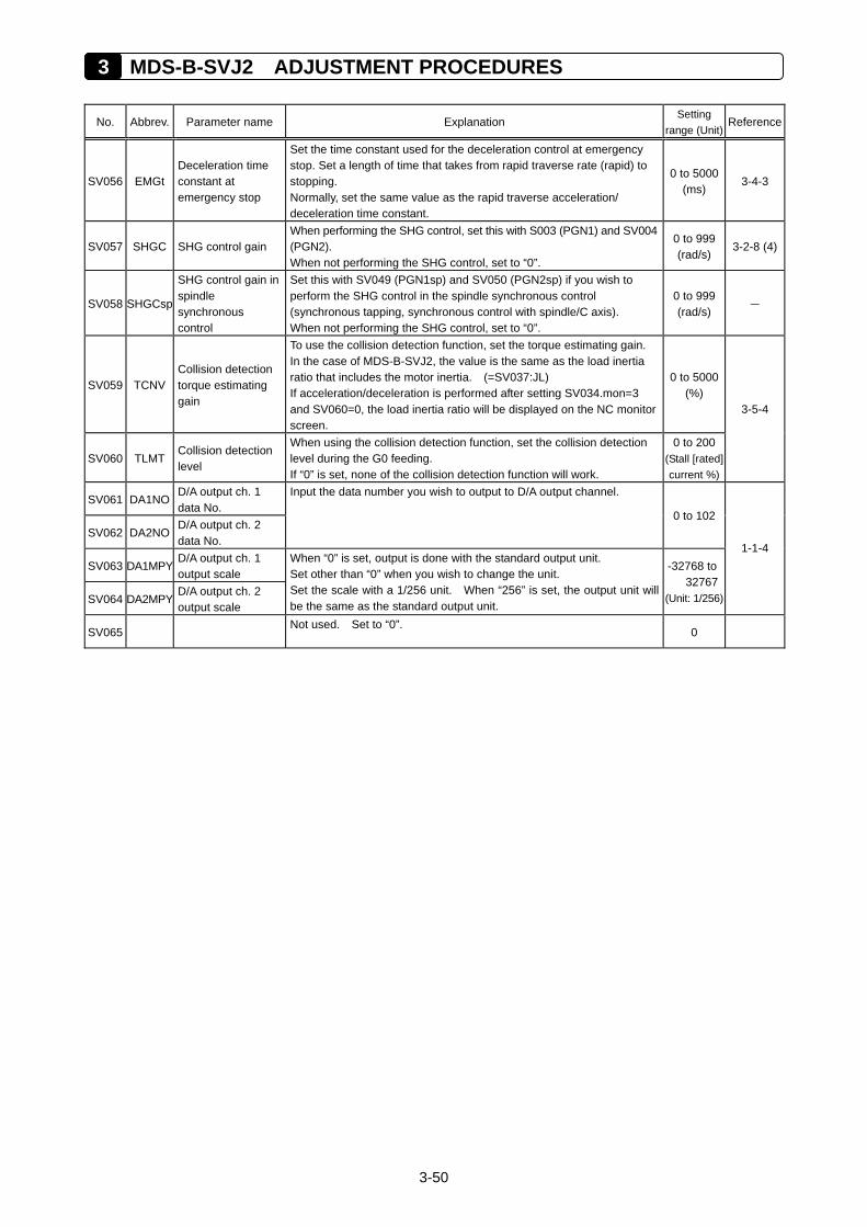
3 MDS-B-SVJ2 ADJUSTMENT PROCEDURES
3-50
No. Abbrev. Parameter name Explanation Setting
range (Unit)Reference
SV056 EMGt Deceleration time constant at emergency stop
Set the time constant used for the deceleration control at emergency stop. Set a length of time that takes from rapid traverse rate (rapid) to stopping. Normally, set the same value as the rapid traverse acceleration/ deceleration time constant.
0 to 5000(ms)
3-4-3
SV057 SHGC SHG control gain When performing the SHG control, set this with S003 (PGN1) and SV004 (PGN2). When not performing the SHG control, set to “0”.
0 to 999 (rad/s)
3-2-8 (4)
SV058 SHGCsp
SHG control gain in spindle synchronous control
Set this with SV049 (PGN1sp) and SV050 (PGN2sp) if you wish to perform the SHG control in the spindle synchronous control (synchronous tapping, synchronous control with spindle/C axis). When not performing the SHG control, set to “0”.
0 to 999 (rad/s)
–
SV059 TCNV Collision detection torque estimating gain
To use the collision detection function, set the torque estimating gain. In the case of MDS-B-SVJ2, the value is the same as the load inertia ratio that includes the motor inertia. (=SV037:JL) If acceleration/deceleration is performed after setting SV034.mon=3 and SV060=0, the load inertia ratio will be displayed on the NC monitor screen.
0 to 5000(%)
SV060 TLMT Collision detection level
When using the collision detection function, set the collision detection level during the G0 feeding. If “0” is set, none of the collision detection function will work.
0 to 200 (Stall [rated] current %)
3-5-4
SV061 DA1NO D/A output ch. 1 data No.
Input the data number you wish to output to D/A output channel.
SV062 DA2NO D/A output ch. 2 data No.
0 to 102
SV063 DA1MPY D/A output ch. 1 output scale
SV064 DA2MPY D/A output ch. 2 output scale
When “0” is set, output is done with the standard output unit. Set other than “0” when you wish to change the unit. Set the scale with a 1/256 unit. When “256” is set, the output unit will be the same as the standard output unit.
-32768 to 32767
(Unit: 1/256)
1-1-4
SV065 Not used. Set to “0”.
0
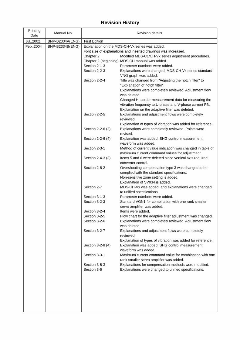
Revision History
Printing Date
Manual No. Revision details
Jul.,2002 BNP-B2334A(ENG) First Edition Feb.,2004 BNP-B2334B(ENG) Explanation on the MDS-CH-Vx series was added.
Font size of explanations and inserted drawings was increased. Chapter 2 Modified MDS-C1/CH-Vx series adjustment procedures. Chapter 2 (beginning) MDS-CH manual was added. Section 2-1-3 Parameter numbers were added. Section 2-2-3 Explanations were changed. MDS-CH-Vx series standard
VNG graph was added. Section 2-2-4 Title was changed from "Adjusting the notch filter" to
"Explanation of notch filter". Explanations were completely reviewed. Adjustment flow was deleted. Changed Hi-corder measurement data for measuring the vibration frequency to U-phase and V-phase current FB. Explanation on the adaptive filter was deleted.
Section 2-2-5 Explanations and adjustment flows were completely reviewed. Explanation of types of vibration was added for reference.
Section 2-2-6 (2) Explanations were completely reviewed. Points were revised.
Section 2-2-6 (4) Explanation was added. SHG control measurement waveform was added.
Section 2-3-1 Method of current value indication was changed in table of maximum current command values for adjustment.
Section 2-4-3 (3) Items 5 and 6 were deleted since vertical axis required converter control.
Section 2-5-2 Overshooting compensation type 3 was changed to be complied with the standard specifications. Non-sensitive zone setting is added. Explanation of SV034 is added.
Section 2-7 MDS-CH-Vx was added, and explanations were changed to unified specifications.
Section 3-1-3 Parameter numbers were added. Section 3-2-3 Standard VGN1 for combination with one rank smaller
servo amplifier was added. Section 3-2-4 Items were added. Section 3-2-5 Flow chart for the adaptive filter adjustment was changed. Section 3-2-6 Explanations were completely reviewed. Adjustment flow
was deleted. Section 3-2-7 Explanations and adjustment flows were completely
reviewed. Explanation of types of vibration was added for reference.
Section 3-2-8 (4) Explanation was added. SHG control measurement waveform was added.
Section 3-3-1 Maximum current command value for combination with one rank smaller servo amplifier was added.
Section 3-5-3 Explanations for compensation methods were modified. Section 3-6 Explanations were changed to unified specifications.

BNP-B2334B(ENG)
AC SERVO
008ー201
(0402)MEE
Specifications subject to change without notice.Printed in Japan on recycled paper.
MODEL
Manual No.
MODELCODE
MITSUBISHI ELECTRIC CORPORATION HEAD OFFICE : MITSUBISHI DENKI BLDG., 2-2-3, MARUNOUCHI, CHIYODA-KU, TOKYO 100-8310, JAPAN


![AFC Adjustment[1]](https://img.pdfslide.us/doc/110x75/577d27901a28ab4e1ea4354c/afc-adjustment1.jpg)