Embed Size (px)
Citation preview

80-00156-01, Rev. D
MegaRAID SAS Software
USER’SGUIDE
A p r i l 2 0 0 8

iiCopyright © 2005-2008 by LSI Corporation. All rights reserved.
This document contains proprietary information of LSI Corporation. The informa-tion contained herein is not to be used by or disclosed to third parties without the express written permission of an officer of LSI Corporation.
Document 80-00156-01, Rev. D (April 2008)This document describes the LSI Corporation’s MegaRAID Storage Manager software. This document will remain the official reference source for all revisions/releases of this product until rescinded by an update.
LSI Corporation reserves the right to make changes to any products herein at any time without notice. LSI does not assume any responsibility or liability arising out of the application or use of any product described herein, except as expressly agreed to in writing by LSI; nor does the purchase or use of a product from LSI convey a license under any patent rights, copyrights, trademark rights, or any other of the intellectual property rights of LSI or third parties.
Copyright © 2005-2008 by LSI Corporation. All rights reserved.
TRADEMARK ACKNOWLEDGMENTLSI, the LSI logo design, iBBU, MegaRAID, and MegaRAID Storage Manager are trademarks or registered trademarks of LSI Corporation. Microsoft and Windows are trademarks or registered trademarks of Microsoft Corporation. Linux is a registered trademark of Linus Torvalds. Intel and Pentium are registered trademarks of Intel Corporation. SCO and SCO UnixWare are registered trademarks and OpenServer is a trademark of the SCO Group, Inc. This product includes software developed by the Apache Software Foundation (http://www.apache.org/). All other brand and product names may be trademarks of their respective companies.
KL/CD
To receive product literature, visit us at http://www.lsi.com.
For a current list of our distributors, sales offices, and design resource centers, view our web page located at
http://www.lsi.com/cm/ContactSearch.do?locale=EN

MegaRAID SAS Software User’s Guide iiiCopyright © 2005-2008 by LSI Corporation. All rights reserved.
Preface
This document explains how to use the MegaRAID Storage Manager™ software, WebBIOS, and Command Line Interface (CLI) utilities to configure, monitor, and maintain MegaRAID® SAS RAID controllers and the storage-related devices connected to them.
Audience
This document assumes that you are familiar with SAS controllers and configuration utilities. The people who benefit from this book are network administrators who need to create storage configurations on LSI SAS controllers.
Organization
This document has the following chapters and appendixes:
• Chapter 1, “Introduction to RAID,” describes RAID (Redundant Array of Independent Disks), RAID functions and benefits, RAID components, RAID levels, and configuration strategies. In addition, it defines the RAID availability concept, and offers tips for configuration planning.
• Chapter 2, “WebBIOS Configuration Utility,” explains how to use the pre-boot WebBIOS Configuration Utility to create and manage storage configurations.
• Chapter 3, “MegaRAID Command Tool,” explains how to use the MegaRAID Command Tool to create and manage storage configurations. The MegaRAID Command Tool is a CLI application for SAS.

iv PrefaceCopyright © 2005-2008 by LSI Corporation. All rights reserved.
• Chapter 4, “MegaRAID Storage Manager Overview and Installation,” introduces the main features of MegaRAID Storage Manager software and explains how to install it.
• Chapter 5, “MegaRAID Storage Manager Window and Menus,” describes the layout of the MegaRAID Storage Manager window and lists the available menu options.
• Chapter 6, “Configuration,” describes how to use the MegaRAID Storage Manager software to configure or reconfigure storage devices, how to save configurations, and how to apply saved configurations to a controller.
• Chapter 7, “Monitoring System Events and Storage Devices,” explains how the MegaRAID Storage Manager software monitors the status of storage configurations and devices and displays information about them.
• Chapter 8, “Maintaining and Managing Storage Configurations,” describes the MegaRAID Storage Manager maintenance functions for virtual drives and other storage devices.
• Appendix A, “Events and Messages,” provides descriptions of the MegaRAID Storage Manager events.
• Appendix B, “Glossary,” contains definitions of storage-related terms.
Conventions
Note: Notes contain supplementary information that can have an effect on system performance.
Caution: Cautions are notifications that an action has the potential to adversely affect equipment operation, system performance, or data integrity.

Preface vCopyright © 2005-2008 by LSI Corporation. All rights reserved.
Revision History
DocumentNumber
DateRevision Remarks
80-00156-01 Rev. D April 2008 Updated the RAID overview section. Updated the WebBIOS Configuration Utility and the MegaRAID Storage Manager. Updated the MegaCLI commands.
80-00156-01 Rev. C July 2007Version 2.1
Updated operating system support for MegaCLI.
80-00156-01 Rev. B June 2007Version 2.0
Updated the WebBIOS Configuration Utility and the Mega-RAID Storage Manager. Updated the MegaCLI commands. Added the RAID introduction chapter.
80-00156-01 Rev. A August 2006Version 1.1
Corrected the procedure for creating RAID 10 and RAID 50 drive groups in the WebBIOS Configuration Utility.
DB15-000339-00 December 2005Version 1.0
Initial release of this document.

vi PrefaceCopyright © 2005-2008 by LSI Corporation. All rights reserved.

MegaRAID SAS Software User’s Guide viiCopyright © 2005-2008 by LSI Corporation. All rights reserved.
Contents
Chapter 1Introduction to RAID
1.1 RAID Description 1-11.2 RAID Benefits 1-11.3 RAID Functions 1-11.4 Components and Features 1-2
1.4.1 Physical Array 1-21.4.2 Virtual Drive 1-21.4.3 RAID Drive Group 1-31.4.4 Fault Tolerance 1-31.4.5 Consistency Check 1-51.4.6 Copyback 1-51.4.7 Background Initialization 1-61.4.8 Patrol Read 1-71.4.9 Disk Striping 1-71.4.10 Disk Mirroring 1-81.4.11 Parity 1-91.4.12 Disk Spanning 1-101.4.13 Hot Spares 1-111.4.14 Disk Rebuilds 1-131.4.15 Rebuild Rate 1-141.4.16 Hot Swap 1-141.4.17 Drive States 1-141.4.18 Virtual Drive States 1-151.4.19 Enclosure Management 1-16
1.5 RAID Levels 1-161.5.1 Summary of RAID Levels 1-161.5.2 Selecting a RAID Level 1-171.5.3 RAID 0 1-17

viii ContentsCopyright © 2005-2008 by LSI Corporation. All rights reserved.
1.5.4 RAID 1 1-181.5.5 RAID 5 1-191.5.6 RAID 6 1-201.5.7 RAID 10 1-221.5.8 RAID 50 1-231.5.9 RAID 60 1-24
1.6 RAID Configuration Strategies 1-261.6.1 Maximizing Fault Tolerance 1-271.6.2 Maximizing Performance 1-281.6.3 Maximizing Storage Capacity 1-30
1.7 RAID Availability 1-311.7.1 RAID Availability Concept 1-31
1.8 Configuration Planning 1-321.8.1 Number of Drives 1-331.8.2 Drive Group Purpose 1-33
Chapter 2WebBIOS Configuration Utility
2.1 Overview 2-12.2 Starting the WebBIOS CU 2-22.3 WebBIOS CU Main Screen Options 2-32.4 Creating a Storage Configuration 2-5
2.4.1 Selecting the Configuration with the Configuration Wizard 2-6
2.4.2 Using Auto Configuration 2-72.4.3 Using Custom Configuration 2-8
2.5 Viewing and Changing Device Properties 2-502.5.1 Viewing and Changing Controller Properties 2-512.5.2 Viewing and Changing Virtual Drive Properties 2-542.5.3 Viewing Drive Properties 2-552.5.4 Viewing Battery Backup Unit Information 2-57
2.6 Viewing System Event Information 2-582.7 Managing Configurations 2-60
2.7.1 Running a Consistency Check 2-602.7.2 Deleting a Virtual Drive 2-602.7.3 Importing or Clearing a Foreign Configuration 2-612.7.4 Migrating the RAID Level of a Virtual Drive 2-65

Contents ixCopyright © 2005-2008 by LSI Corporation. All rights reserved.
Chapter 3MegaRAID Command Tool
3.1 Product Overview 3-23.2 Novell, SCO, and Solaris Operating System Support 3-33.3 MegaCLI Version 1.00.22 Upgrade for Linux 3-43.4 Command Line Abbreviations and Conventions 3-4
3.4.1 Abbreviations Used in the Command Line 3-53.4.2 Conventions 3-5
3.5 Adapter Property-Related Options 3-63.5.1 Display Adapter Properties 3-63.5.2 Display Number of Controllers Supported 3-73.5.3 Enable or Disable Automatic Rebuild 3-73.5.4 Flush Adapter Cache 3-73.5.5 Set Adapter Properties 3-83.5.6 Display Specified Adapter Properties 3-93.5.7 Set Factory Defaults 3-103.5.8 Set SAS Address 3-103.5.9 Set Time and Date on Adapter 3-103.5.10 Display Time and Date on Adapter 3-10
3.6 Patrol Read-Related Adapter Properties 3-113.6.1 Set Patrol Read Options 3-113.6.2 Set Patrol Read Delay Interval 3-11
3.7 BIOS-Related Properties 3-123.7.1 Set or Display Bootable Virtual Drive ID 3-123.7.2 Select BIOS Status Options 3-12
3.8 Battery Backup Unit-Related Properties 3-133.8.1 Display BBU Information 3-133.8.2 Display BBU Status Information 3-133.8.3 Display BBU Capacity 3-143.8.4 Display BBU Design Parameters 3-153.8.5 Display Current BBU Properties 3-153.8.6 Start BBU Learning Cycle 3-163.8.7 Place Battery in Low-Power Storage Mode 3-163.8.8 Set BBU Properties 3-16
3.9 Options for Displaying Logs Kept at Firmware Level 3-173.9.1 Event Log Management 3-173.9.2 Set BBU Terminal Logging 3-18

x ContentsCopyright © 2005-2008 by LSI Corporation. All rights reserved.
3.10 Configuration-Related Options 3-183.10.1 Create a RAID Drive Group from All Unconfigured Good
Drives 3-183.10.2 Add RAID 0, 1, 5, or 6 Configuration 3-193.10.3 Add RAID 10, 50, or 60 Configuration 3-213.10.4 Clear the Existing Configuration 3-213.10.5 Save the Configuration on the Adapter 3-223.10.6 Restore the Configuration Data from File 3-223.10.7 Manage Foreign Configuration Information 3-223.10.8 Delete Specified Virtual Drive(s) 3-233.10.9 Display the Free Space 3-23
3.11 Virtual Drive-Related Options 3-243.11.1 Display Virtual Drive Information 3-243.11.2 Change the Virtual Drive Cache and Access Parameters
3-243.11.3 Display the Virtual Drive Cache and Access Parameters
3-253.11.4 Manage Virtual Drives Initialization 3-253.11.5 Manage a Consistency Check 3-263.11.6 Manage a Background Initialization 3-263.11.7 Perform a Virtual Drive Reconstruction 3-273.11.8 Display Information about Virtual Drives and Drives3-273.11.9 Display the Number of Virtual Drives 3-27
3.12 Drive-Related Options 3-283.12.1 Display Drive Information 3-283.12.2 Set the Drive State to Online 3-283.12.3 Set the Drive State to Offline 3-283.12.4 Change the Drive State to Unconfigured Good 3-293.12.5 Change Drive State 3-293.12.6 Manage a Drive Initialization 3-303.12.7 Rebuild a Drive 3-303.12.8 Locate the Drive(s) and Activate LED 3-313.12.9 Mark the Configured Drive as Missing 3-313.12.10 Display the Drives in Missing Status 3-313.12.11 Replace the Configured Drives and Start an Automatic
Rebuild 3-313.12.12 Prepare the Unconfigured Drive for Removal 3-323.12.13 Display Total Number of Drives 3-32

Contents xiCopyright © 2005-2008 by LSI Corporation. All rights reserved.
3.12.14 Display List of Physical Devices 3-323.13 Enclosure-Related Options 3-333.14 Flashing the Firmware 3-33
3.14.1 Flash the Firmware with the ROM File 3-333.14.2 Flash the Firmware in Mode 0 with the ROM File 3-34
3.15 SAS Topology 3-343.16 Diagnostic-Related Options 3-35
3.16.1 Start Adapter Diagnostics 3-353.16.2 Start Battery Test 3-353.16.3 Start NVRAM Diagnostic 3-35
3.17 Miscellaneous Options 3-363.17.1 Display the MegaCLI Version 3-363.17.2 Display Help for MegaCLI 3-36
Chapter 4MegaRAID Storage Manager Overview and Installation
4.1 Overview 4-14.1.1 Creating Storage Configurations 4-14.1.2 Monitoring Storage Devices 4-24.1.3 Maintaining Storage Configurations 4-2
4.2 Hardware and Software Requirements 4-24.3 Installation 4-3
4.3.1 Installing MegaRAID Storage Manager Software on Microsoft Windows 4-3
4.3.2 Installing MegaRAID Storage Manager Software for Linux 4-8
4.3.3 Linux Error Messages 4-94.4 MegaRAID Storage Manager Support and Installation on VMWare
4-94.4.1 Installing MegaRAID Storage Manager (MSM) for
VMWare 4-104.4.2 Uninstalling MegaRAID Storage Manager 4-104.4.3 Uninstalling MegaRAID Storage Manager for VMWare
4-10

xii ContentsCopyright © 2005-2008 by LSI Corporation. All rights reserved.
Chapter 5MegaRAID Storage Manager Window and Menus
5.1 Starting MegaRAID Storage Manager Software 5-15.2 MegaRAID Storage Manager Window 5-4
5.2.1 Physical/Logical View Panel 5-55.2.2 Properties/Operations/Graphical View Panel 5-65.2.3 Event Log Panel 5-85.2.4 Menu Bar 5-9
Chapter 6Configuration
6.1 Creating a New Storage Configuration 6-16.1.1 Understanding Virtual Drive Parameters 6-36.1.2 Using Auto Configuration 6-56.1.3 Using Guided Configuration 6-76.1.4 Using Manual Configuration: RAID 0 6-106.1.5 Using Manual Configuration: RAID 1 6-126.1.6 Using Manual Configuration: RAID 5 6-146.1.7 Using Manual Configuration: RAID 6 6-156.1.8 Using Manual Configuration: RAID 10 6-166.1.9 Using Manual Configuration: RAID 50 6-176.1.10 Using Manual Configuration: RAID 60 6-18
6.2 Adding Hot Spare Drives 6-206.3 Changing Adjustable Task Rates 6-216.4 Changing Virtual Drive Properties 6-246.5 Changing a Virtual Drive Configuration 6-25
6.5.1 Adding a Drive to a Configuration 6-266.5.2 Removing a Drive from a Configuration6-276.5.3 Changing the RAID Level of a Configuration 6-28
6.6 Deleting a Virtual Drive 6-286.7 Saving a Storage Configuration to Drive 6-296.8 Clearing a Storage Configuration from a Controller 6-296.9 Adding a Saved Storage Configuration 6-30

Contents xiiiCopyright © 2005-2008 by LSI Corporation. All rights reserved.
Chapter 7Monitoring System Events and Storage Devices
7.1 Monitoring System Events 7-17.2 Configuring Event Notifications 7-3
7.2.1 Setting Alert Delivery Rules 7-47.2.2 Changing the Event Severity 7-57.2.3 Defining Exceptions 7-67.2.4 Selecting Email Settings 7-8
7.3 Monitoring Controllers 7-107.4 Monitoring Drives 7-127.5 Running a Patrol Read 7-147.6 Monitoring Virtual Drives 7-167.7 Monitoring Enclosures 7-187.8 Monitoring Battery Backup Units 7-19
7.8.1 Battery Learn Cycle 7-217.9 Monitoring Rebuilds and Other Processes 7-21
Chapter 8Maintaining and Managing Storage Configurations
8.1 Initializing a Virtual Drive 8-18.2 Running a Consistency Check 8-28.3 Scanning for New Drives 8-38.4 Rebuilding a Drive 8-38.5 Making a Drive Offline or Missing 8-48.6 Upgrading the Firmware 8-5
Appendix AEvents and Messages
Appendix BGlossary
Customer Feedback

xiv ContentsCopyright © 2005-2008 by LSI Corporation. All rights reserved.

Contents xvCopyright © 2005-2008 by LSI Corporation. All rights reserved.
Figures1.1 Example of Disk Striping (RAID 0) 1-71.2 Example of Disk Mirroring (RAID 1) 1-81.3 Example of Distributed Parity (RAID 5) 1-91.4 Example of Disk Spanning 1-101.5 RAID 0 Drive Group Example with Two Drives 1-181.6 RAID 1 Drive Group 1-191.7 RAID 5 Drive Group with Six Drives 1-201.8 Example of Distributed Parity across Two Blocks in a Stripe
(RAID 6) 1-221.9 RAID 10 Level Virtual Drive 1-231.10 RAID 50 Level Virtual Drive 1-241.11 RAID 60 Level Virtual Drive 1-262.1 WebBIOS CU Main Screen 2-32.2 WebBIOS Configuration Wizard Screen 2-62.3 WebBIOS Disk Group Definition Screen 2-92.4 WebBIOS Virtual Disk Definition Screen 2-102.5 RAID 0 Configuration Preview 2-132.6 WebBIOS Disk Group Definition Screen 2-142.7 WebBIOS Virtual Disk Definition Screen 2-152.8 RAID 1 Configuration Preview 2-182.9 WebBIOS Disk Group Definition Screen 2-192.10 WebBIOS Virtual Disk Definition Screen 2-202.11 RAID 5 Configuration Preview 2-232.12 WebBIOS Disk Group Definition Screen 2-252.13 WebBIOS Virtual Disk Definition Screen 2-262.14 RAID 6 Configuration Preview 2-292.15 WebBIOS Disk Group Definition Screen 2-312.16 WebBIOS Span Definition Screen 2-322.17 WebBIOS Virtual Disk Definition Screen 2-332.18 RAID 10 Configuration Preview 2-362.19 WebBIOS Disk Group Definition Screen 2-382.20 WebBIOS Span Definition Screen 2-392.21 WebBIOS Virtual Disk Definition Screen 2-402.22 RAID 50 Configuration Preview 2-432.23 WebBIOS Disk Group Definition Screen 2-452.24 WebBIOS Span Definition Screen 2-46

xvi ContentsCopyright © 2005-2008 by LSI Corporation. All rights reserved.
2.25 WebBIOS Virtual Disk Definition Screen 2-472.26 RAID 60 Configuration Preview 2-502.27 First Adapter Properties Screen 2-512.28 Second Adapter Properties Screen 2-522.29 Virtual Disk Screen 2-542.30 Physical Drive Screen 2-562.31 Battery Module Screen 2-582.32 Event Information Screen 2-592.33 Foreign Configuration Screen 2-622.34 Foreign Configuration Preview Screen 2-624.1 Customer Information Screen 4-44.2 Setup Type Screen 4-54.3 Setup Type Screen 4-64.4 Custom Setup Screen 4-74.5 Server Screen 4-85.1 Select Server Window 5-25.2 Server Login Window 5-35.3 Main MegaRAID Storage Manager Window 5-45.4 Operations Tab 5-75.5 Graphical View Tab 5-86.1 First Configuration Wizard Screen 6-26.2 Auto Configuration Screen 6-66.3 First Guided Configuration Screen 6-86.4 Second Guided Configuration Screen 6-96.5 First Manual Configuration Screen 6-106.6 Manual Configuration – Defining a Virtual Drive 6-116.7 Creating a Global Hot Spare 6-216.8 Set Adjustable Task Rates 6-236.9 Set Virtual Disk Properties 6-246.10 Reconstruction Wizard 6-267.1 Event Information Window 7-27.2 Event Notification Configuration Screen 7-47.3 Change Events Severity 7-57.4 Add an Event to the Exceptions List 7-77.5 Edit Delivery Methods for Exception Events 7-87.6 Email Settings 7-97.7 Add Email Address Dialog Box 7-97.8 Controller Information 7-11

Contents xviiCopyright © 2005-2008 by LSI Corporation. All rights reserved.
7.9 Drive Information 7-137.10 Patrol Read Configuration 7-157.11 Virtual Disk Properties 7-177.12 Enclosure Information – Graphical View 7-197.13 Battery Backup Unit Information 7-207.14 Group Show Progress Window 7-21

xviii ContentsCopyright © 2005-2008 by LSI Corporation. All rights reserved.

Contents xixCopyright © 2005-2008 by LSI Corporation. All rights reserved.
Tables1.1 Types of Parity 1-91.2 Spanning for RAID 10, RAID 50, and RAID 60 1-111.3 Drive States 1-141.4 Virtual Drive States 1-151.5 RAID 0 Overview 1-181.6 RAID 1 Overview 1-181.7 RAID 5 Overview 1-201.8 RAID 6 Overview 1-211.9 RAID 10 Overview 1-231.10 RAID 50 Overview 1-241.11 RAID 60 Overview 1-251.12 RAID Levels and Fault Tolerance 1-271.13 RAID Levels and Performance 1-281.14 RAID Levels and Capacity 1-301.15 Factors to Consider for Drive Group Configuration 1-332.1 WebBIOS CU Toolbar Icons 2-42.2 Adapter Properties Menu Options 2-522.3 Additional Drives Required for RAID-Level Migration 2-663.1 Command Line Abbreviations 3-53.2 Conventions 3-53.3 Adapter Parameters 3-73.4 Number of Controllers Supported 3-73.5 Enable or Disable Automatic Rebuild 3-73.6 Cache Flush on Selected Adapter 3-83.7 Set Adapter Properties 3-83.8 Display Specified Adapter Properties 3-93.9 Set Factory Defaults 3-103.10 Set SAS Address on Adapter 3-103.11 Set Time and Date on Adapter 3-103.12 Display Time and Date on Adapter 3-103.13 Set Patrol Read Options 3-113.14 Set Patrol Read Delay Interval 3-123.15 Bootable Virtual Drive ID 3-123.16 Options for BIOS Status 3-123.17 Display BBU Information 3-133.18 Display BBU Status Information 3-14

xx ContentsCopyright © 2005-2008 by LSI Corporation. All rights reserved.
3.19 Display BBU Capacity Information 3-153.20 Display BBU Design Parameters 3-153.21 Display Current BBU Properties 3-163.22 Start BBU Learning Cycle 3-163.23 Place Battery in Low-Power Storage Mode 3-163.24 Set BBU Properties 3-173.25 Event Log Management 3-173.26 Set BBU Terminal Logging 3-183.27 Create a Drive Group from All of the Unconfigured Drives 3-193.28 Add RAID 0, 1, 5, or 6 Configuration 3-193.29 Add RAID 10, 50, or 60 Configuration 3-213.30 Clear Existing Configuration 3-213.31 Save Configuration on the Adapter 3-223.32 Restore Configuration Data from File 3-223.33 Manage Foreign Configuration Information 3-233.34 Delete Specified Virtual Drives 3-233.35 Display Free Space 3-233.36 Display Virtual Drive Information 3-243.37 Change Virtual Drive Cache and Access Parameters 3-243.38 Display Virtual Drive Cache and Access Parameters 3-253.39 Manage Virtual Drive Initialization 3-253.40 Manage Consistency Check 3-263.41 Manage Background Initialization 3-263.42 Virtual Drive Reconstruction 3-273.43 Display Virtual Drive and Drive Information 3-273.44 Display Number of Virtual Drives 3-273.45 Display Drive Information 3-283.46 Set Drive State to Online 3-283.47 Set Drive State to Offline 3-293.48 Change Drive State to Unconfigured Good 3-293.49 Change Drive State 3-293.50 Drive Initialization 3-303.51 Rebuild a Drive 3-303.52 Locate Drive and Activate LED 3-313.53 Mark Configured Drive as Missing 3-313.54 Display Drives in Missing Status 3-313.55 Replace Configured Drive(s) and Start Automatic Rebuild 3-313.56 Prepare Unconfigured Drive(s) for Removal 3-32

Contents xxiCopyright © 2005-2008 by LSI Corporation. All rights reserved.
3.57 Display Number of Drives Attached to an Adapter 3-323.58 Display List of Physical Devices Attached to Adapter(s) 3-323.59 Display Enclosure Information 3-333.60 Flash Firmware with ROM File 3-333.61 Flash Firmware in Mode 0 with ROM File 3-343.62 Display PHY Connection Information 3-343.63 Start Diagnostics Setting 3-353.64 Start Battery Test 3-353.65 Start NVRAM Diagnostic 3-353.66 Display MegaCLI Version 3-363.67 Display Help for MegaCLI 3-367.1 Event Severity Levels 7-2A.1 Event Error Levels A-1A.2 Event Messages A-2

xxii ContentsCopyright © 2005-2008 by LSI Corporation. All rights reserved.

MegaRAID SAS Software User’s Guide 1-1Copyright © 2005-2008 by LSI Corporation. All rights reserved.
Chapter 1Introduction to RAID
This chapter describes RAID (Redundant Array of Independent Disks), RAID functions and benefits, RAID components, RAID levels, and configuration strategies. In addition, it defines the RAID availability concept, and offers tips for configuration planning.
1.1 RAID Description
RAID is an array, or group of multiple independent physical drives that provide high performance and fault tolerance. A RAID drive group improves I/O (input/output) performance and reliability. The RAID drive group appears to the host computer as a single storage unit or as multiple virtual units. I/O is expedited because several drives can be accessed simultaneously.
1.2 RAID Benefits
RAID drive groups improve data storage reliability and fault tolerance compared to single-drive storage systems. Data loss resulting from a drive failure can be prevented by reconstructing missing data from the remaining drives. RAID has gained popularity because it improves I/O performance and increases storage subsystem reliability.
1.3 RAID Functions
Virtual drives are drive groups or spanned drive groups that are available to the operating system. The storage space in a virtual drive is spread across all of the drives in the drive group.

1-2 Introduction to RAIDCopyright © 2005-2008 by LSI Corporation. All rights reserved.
Your drives must be organized into virtual drives in a drive group and they must be able to support the RAID level that you select. Below are some common RAID functions:
• Creating hot spare drives
• Configuring drive groups and virtual drives
• Initializing one or more virtual drives
• Accessing controllers, virtual drives, and drives individually
• Rebuilding failed drives
• Verifying that the redundancy data in virtual drives using RAID level 1, 5, 6, 10, 50, or 60 is correct
• Reconstructing virtual drives after changing RAID levels or adding a drive to a drive group
• Selecting a host controller to work on
1.4 Components and Features
RAID levels describe a system for ensuring the availability and redundancy of data stored on large disk subsystems. See Section 1.5, “RAID Levels,” for detailed information about RAID levels. The following subsections describes the components of RAID drive groups and RAID levels.
1.4.1 Physical Array
A physical array is a group of drives. The drives are managed in partitions known as virtual drives.
1.4.2 Virtual Drive
A virtual drive is a partition in a drive group that is made up of contiguous data segments on the drives. A virtual drive can consist of an entire drive group, more than one entire drive group, a part of a drive group, parts of more than one drive group, or a combination of any two of these conditions.

Components and Features 1-3Copyright © 2005-2008 by LSI Corporation. All rights reserved.
1.4.3 RAID Drive Group
A RAID drive group is one or more drives controlled by the RAID controller.
1.4.4 Fault Tolerance
Fault tolerance is the capability of the subsystem to undergo a drive failure or failures without compromising data integrity, and processing capability. The RAID controller provides this support through redundant drive groups in RAID levels 1, 5, 6, 10, 50, and 60. The system can still work properly even with drive failure in a drive group, though performance can be degraded to some extent.
In a span of RAID 1 drive groups, each RAID 1 drive group has two drives and can tolerate one drive failure. The span of RAID 1 drive groups can contain up to 32 drives, and tolerate up to 16 drive failures - one in each drive group. A RAID 5 drive group can tolerate one drive failure in each RAID 5 drive group. A RAID 6 drive group can tolerate up to two drive failures.
Each spanned RAID 10 virtual drive can tolerate multiple drive failures, as long as each failure is in a separate drive group. A RAID 50 virtual drive can tolerate two drive failures, as long as each failure is in a separate drive group. RAID 60 drive groups can tolerate up to two drive failures in each drive group.
Note: RAID level 0 is not fault tolerant. If a drive in a RAID 0 drive group fails, the whole virtual drive (all drives associated with the virtual drive) will fail.
Fault tolerance is often associated with system availability because it allows the system to be available during the failures. However, this means that it is also important for the system to be available during the repair of the problem.
A hot spare is an unused drive that, in case of a disk failure in a redundant RAID drive group, can be used to rebuild the data and re-establish redundancy. After the hot spare is automatically moved into the RAID drive group, the data is automatically rebuilt on the hot spare drive. The RAID drive group continues to handle requests while the rebuild occurs.

1-4 Introduction to RAIDCopyright © 2005-2008 by LSI Corporation. All rights reserved.
Auto-rebuild allows a failed drive to be replaced and the data automatically rebuilt by “hot-swapping” the drive in the same drive bay. The RAID drive group continues to handle requests while the rebuild occurs.
1.4.4.1 Multipathing
The firmware provides support for detecting and using multiple paths from the RAID controllers to the SAS devices that are in enclosures. Devices connected to enclosures have multiple paths to them. With redundant paths to the same port of a device, if one path fails, another path can be used to communicate between the controller and the device. Using multiple paths with load balancing, instead of a single path, can increase reliability through redundancy.
Applications show the enclosures and the drives connected to the enclosures. The firmware dynamically recognizes new enclosures added to a configuration along with their contents (new drives). In addition, the firmware dynamically adds the enclosure and its contents to the management entity currently in-use.
Multipathing provides the following features:
• Support for failover, in the event of path failure
• Auto-discovery of new or restored paths while the system is online, and reversion to system load balancing policy
• Measurable bandwidth improvement to the multi-path device
• Support for changing the load balancing path while the system is online
The firmware determines whether enclosure modules (ESMs) are part of the same enclosure. When a new enclosure module is added (allowing multi-path) or removed (going single path), an Alert Event Notification (AEN) is generated. Alerts about drives contain correct information about the "enclosure", when the drives are connected by multiple paths. The enclosure module detects partner ESMs and issue events appropriately.
In a system with two ESMs, you can replace one of the ESMs without affecting the virtual drive availability. For example, the controller can run heavy I/Os, and when you replace one of the ESM modules, I/Os should

Components and Features 1-5Copyright © 2005-2008 by LSI Corporation. All rights reserved.
not stop. The controller uses different paths to balance the load on the entire system.
In the MegaRAID Storage Manager utility, when multiple paths are available to a drive, the drive information will show only one enclosure. The utility shows that a redundant path is available to a drive. All drives with a redundant path display this information. The firmware supports online replacement of enclosure modules.
1.4.5 Consistency Check
The Consistency Check operation verifies correctness of the data in virtual drives that use RAID levels 1, 5, 6, 10, 50, and 60. (RAID 0 does not provide data redundancy). For example, in a system with parity, checking consistency means computing the data on one drive and comparing the results to the contents of the parity drive.
Note: It is recommended that you perform a consistency check at least once a month.
1.4.6 Copyback
The copyback feature allows you to copy data from a source drive of a virtual drive to a destination drive that is not a part of the virtual drive. Copyback is often used to create or restore a specific physical configuration for a drive group (for example, a specific arrangement of drive group members on the device I/O buses). Copyback can be run automatically or manually.
Typically, when a drive fails or is expected to fail, the data is rebuilt on a hot spare. The failed drive is replaced with a new disk. Then the data is copied from the hot spare to the new drive, and the hot spare reverts from a rebuild drive to its original hot spare status. The copyback operation runs as a background activity, and the virtual drive is still available online to the host.
Copyback is also initiated when the first Self-Monitoring Analysis and Reporting Technology (SMART) error occurs on a drive that is part of a virtual drive. The destination drive is a hot spare that qualifies as a rebuild drive. The drive with the SMART error is marked as "failed" only after the successful completion of the copyback. This avoids putting the drive group in degraded status.

1-6 Introduction to RAIDCopyright © 2005-2008 by LSI Corporation. All rights reserved.
Note: During a copyback operation, if the drive group involved in the copyback is deleted because of a virtual drive deletion, the destination drive reverts to an Unconfigured Good state or hot spare state.
Order of Precedence –
In the following scenarios, rebuild takes precedence over the copyback operation:
1. If a copyback operation is already taking place to a hotspare drive, and any virtual drive on the controller degrades, the copyback operation aborts, and a rebuild starts. The rebuild changes the virtual drive to the optimal state.
2. The rebuild operation takes precedence over the copyback operation when the conditions exist to start both operations. For example:
a. Where the hotspare is not configured (or unavailable) in the system.
b. There are two drives (both members of virtual drives), with one drive exceeding the SMART error threshold, and the other failed.
c. If you add a hotspare (assume a global hot spare) during a copyback operation, the copyback is aborted, and the rebuild operation starts on the hotspare.
1.4.7 Background Initialization
Background initialization is a consistency check that is forced when you create a virtual drive. The difference between a background initialization and a consistency check is that a background initialization is forced on new virtual drives. This is an automatic operation that starts 5 minutes after you create the virtual drive.
Background initialization is a check for media errors on the drives. It ensures that striped data segments are the same on all drives in a drive group. The default and recommended background initialization rate is 30 percent. Before you change the rebuild rate, you must stop the background initialization or the rate change will not affect the background initialization rate. After you stop background initialization and change the rebuild rate, the rate change takes effect when you restart background initialization.
Components and Features 1-7Copyright © 2005-2008 by LSI Corporation. All rights reserved.
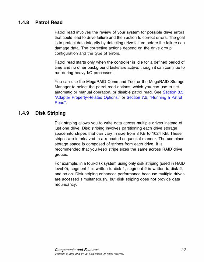
1.4.8 Patrol Read
Patrol read involves the review of your system for possible drive errors that could lead to drive failure and then action to correct errors. The goal is to protect data integrity by detecting drive failure before the failure can damage data. The corrective actions depend on the drive group configuration and the type of errors.
Patrol read starts only when the controller is idle for a defined period of time and no other background tasks are active, though it can continue to run during heavy I/O processes.
You can use the MegaRAID Command Tool or the MegaRAID Storage Manager to select the patrol read options, which you can use to set automatic or manual operation, or disable patrol read. See Section 3.5, “Adapter Property-Related Options,” or Section 7.5, “Running a Patrol Read”.
1.4.9 Disk Striping
Disk striping allows you to write data across multiple drives instead of just one drive. Disk striping involves partitioning each drive storage space into stripes that can vary in size from 8 KB to 1024 KB. These stripes are interleaved in a repeated sequential manner. The combined storage space is composed of stripes from each drive. It is recommended that you keep stripe sizes the same across RAID drive groups.
For example, in a four-disk system using only disk striping (used in RAID level 0), segment 1 is written to disk 1, segment 2 is written to disk 2, and so on. Disk striping enhances performance because multiple drives are accessed simultaneously, but disk striping does not provide data redundancy.

1-8 Introduction to RAIDCopyright © 2005-2008 by LSI Corporation. All rights reserved.
Figure 1.1 Example of Disk Striping (RAID 0)
1.4.9.1 Stripe Width
Stripe width is the number of drives involved in a drive group where striping is implemented. For example, a four-disk drive group with disk striping has a stripe width of four.
1.4.9.2 Stripe Size
The stripe size is the length of the interleaved data segments that the RAID controller writes across multiple drives, not including parity drives. For example, consider a stripe that contains 64 KB of disk space and has 16 KB of data residing on each disk in the stripe. In this case, the stripe size is 64 KB and the strip size is 16 KB.
1.4.9.3 Strip Size
The strip size is the portion of a stripe that resides on a single drive.
1.4.10 Disk Mirroring
With mirroring (used in RAID 1 and RAID 10), data written to one drive is simultaneously written to another drive. The primary advantage of disk mirroring is that it provides 100 percent data redundancy. Because the contents of the disk are completely written to a second disk, data is not lost if one disk fails. In addition, both drives contain the same data at all times, so either disk can act as the operational disk. If one disk fails, the contents of the other disk can be used to run the system and reconstruct the failed disk.
Disk mirroring provides 100 percent redundancy, but is expensive because each drive in the system must be duplicated. Figure 1.2 shows an example of disk mirroring.
Segment 1Segment 5Segment 9
Segment 2Segment 6
Segment 10
Segment 3Segment 7
Segment 11
Segment 4Segment 8
Segment 12

Components and Features 1-9Copyright © 2005-2008 by LSI Corporation. All rights reserved.
Figure 1.2 Example of Disk Mirroring (RAID 1)
1.4.11 Parity
Parity generates a set of redundancy data from two or more parent data sets. The redundancy data can be used to reconstruct one of the parent data sets in the event of a drive failure. Parity data does not fully duplicate the parent data sets, but parity generation can slow the write process. In RAID, this method is applied to entire drives or stripes across all of the drives in a drive group. The types of parity are described in Table 1.1.
RAID 5 combines distributed parity with disk striping. If a single drive fails, it can be rebuilt from the parity and the data on the remaining drives. An example of a RAID 5 drive group is shown in Figure 1.3. RAID 5 uses parity to provide redundancy for one drive failure without duplicating the contents of entire drives. RAID 6 uses distributed parity and disk striping, also, but adds a second set of parity data so that it can survive up to two drive failures.
Segment 1Segment 2Segment 3
Segment 1 DuplicatedSegment 2 DuplicatedSegment 3 Duplicated
Segment 4 Segment 4 Duplicated
Table 1.1 Types of Parity
Parity Type Description
Dedicated The parity data on two or more drives is stored on an additional disk.
Distributed The parity data is distributed across more than one drive in the system.

1-10 Introduction to RAIDCopyright © 2005-2008 by LSI Corporation. All rights reserved.
Figure 1.3 Example of Distributed Parity (RAID 5)
1.4.12 Disk Spanning
Disk spanning allows multiple drives to function like one big drive. Spanning overcomes lack of disk space and simplifies storage management by combining existing resources or adding relatively inexpensive resources. For example, four 20 GB drives can be combined to appear to the operating system as a single 80 GB drive.
Spanning alone does not provide reliability or performance enhancements. Spanned virtual drives must have the same stripe size and must be contiguous. In Figure 1.4, RAID 1 drive groups are turned into a RAID 10 drive group.
Note: Make sure that the spans are in different backplanes, so that if one span fails, you do not lose the whole drive group.
Figure 1.4 Example of Disk Spanning
Note: Spanning two contiguous RAID 0 virtual drives does not produce a new RAID level or add fault tolerance. It does
Segment 1Segment 7
Segment 2Segment 8
Segment 3Segment 9
Segment 4Segment 10
Segment 5Parity (6-10)
Parity (11–15)
Parity (1-5)Segment 6
Note: Parity is distributed across all drives in the drive group.
Segment 12Segment 15 Segment 11Segment 14Segment 13Segment 19Segment 25
Segment 20Segment 23
Segment 18Segment 21
Segment 16Segment 22
Segment 17Parity (21-25)
Parity (26–30)
Parity (16-20)Segment 24Segment 30Segment 27 Segment 29Segment 26 Segment 28
60 GB/s 60 GB/s
Can Be Accessed asOne 120 GB/s Drive
60 GB/s 60 GB/s
Can Be Accessed asOne 120 GB/s Drive

Components and Features 1-11Copyright © 2005-2008 by LSI Corporation. All rights reserved.
increase the capacity of the virtual drive and improves performance by doubling the number of spindles.
1.4.12.1 Spanning for RAID 10, RAID 50, and RAID 60
Table 1.2 describes how to configure RAID 10, RAID 50, and RAID 60 by spanning. The virtual drives must have the same stripe size and the maximum number of spans is eight. The full drive capacity is used when you span virtual drives; you cannot specify a smaller drive capacity.
See Section Chapter 6, “Configuration” for detailed procedures for configuring drive groups and virtual drives, and spanning the drives.
1.4.13 Hot Spares
A hot spare is an extra, unused drive that is part of the disk subsystem. It is usually in standby mode, ready for service if a drive fails. Hot spares permit you to replace failed drives without system shutdown or user intervention. MegaRAID SAS RAID controllers can implement automatic and transparent rebuilds of failed drives using hot spare drives, providing a high degree of fault tolerance and zero downtime.
Note: When running RAID 0 and RAID 5 virtual drives on the same set of drives (a sliced configuration), a rebuild to a hot spare will not occur after a drive failure until the RAID 0 virtual drive is deleted.
The RAID management software allows you to specify drives as hot spares. When a hot spare is needed, the RAID controller assigns the hot
Table 1.2 Spanning for RAID 10, RAID 50, and RAID 60
Level Description
10 Configure RAID 10 by spanning two contiguous RAID 1 virtual drives, up to the maximum number of supported devices for the controller. RAID 10 supports a maximum of eight spans. You must use an even number of drives in each RAID virtual drive in the span. The RAID 1 virtual drives must have the same stripe size.
50 Configure RAID 50 by spanning two contiguous RAID 5 virtual drives. The RAID 5 virtual drives must have the same stripe size.
60 Configure RAID 60 by spanning two contiguous RAID 6 virtual drives. The RAID 6 virtual drives must have the same stripe size.

1-12 Introduction to RAIDCopyright © 2005-2008 by LSI Corporation. All rights reserved.
spare that has a capacity closest to and at least as great as that of the failed drive to take the place of the failed drive. The failed drive is removed from the virtual drive and marked ready awaiting removal once the rebuild to a hot spare begins. You can make hot spares of the drives that are not in a RAID virtual drive.
You can use the RAID management software to designate the hotspare to have enclosure affinity, meaning that if there are drive failures present on a split backplane configuration, the hotspare will be used first on the backplane side that it resides in.
If the hotspare is designated as having enclosure affinity, it will attempt to rebuild any failed drives on the backplane that it resides in before rebuilding any other drives on other backplanes.
Note: If a rebuild to a hot spare fails for any reason, the hot spare drive will be marked as "failed". If the source drive fails, both the source drive and the hot spare drive will be marked as "failed".
There are two types of hot spares:
• Global hot spare
• Dedicated hot spare
1.4.13.1 Global Hot Spare
A global hot spare drive can be used to replace any failed drive in a redundant drive group as long as its capacity is equal to or larger than the coerced capacity of the failed drive. A global hot spare defined on any channel should be available to replace a failed drive on both channels.
1.4.13.2 Dedicated Hot Spare
A dedicated hot spare can be used to replace a failed drive only in a selected drive group. One or more drives can be designated as a member of a spare drive pool. The most suitable drive from the pool is selected for fail over. A dedicated hot spare is used before one from the global hot spare pool.
Hot spare drives can be located on any RAID channel. Standby hot spares (not being used in RAID drive group) are polled every 60 seconds

Components and Features 1-13Copyright © 2005-2008 by LSI Corporation. All rights reserved.
at a minimum, and their status made available in the drive group management software. RAID controllers offer the ability to rebuild with a disk that is in a system, but not initially set to be a hot spare.
Observe the following parameters when using hot spares:
• Hot spares are used only in drive groups with redundancy: RAID levels 1, 5, 6, 10, 50, and 60.
• A hot spare connected to a specific RAID controller can be used to rebuild a drive that is connected to the same controller only.
• You must assign the hot spare to one or more drives through the controller BIOS or use drive group management software to place it in the hot spare pool.
• A hot spare must have free space equal to or greater than the drive it replaces. For example, to replace an 18 GB drive, the hot spare must be 18 GB or larger.
1.4.14 Disk Rebuilds
When a drive in a RAID drive group fails, you can rebuild the drive by recreating the data that was stored on the drive before it failed. The RAID controller recreates the data using the data stored on the other drives in the drive group. Rebuilding can be done only in drive groups with data redundancy, which includes RAID 1, 5, 6, 10, 50, and 60 drive groups.
The RAID controller uses hot spares to rebuild failed drives automatically and transparently, at user-defined rebuild rates. If a hot spare is available, the rebuild can start automatically when a drive fails. If a hot spare is not available, the failed drive must be replaced with a new drive so that the data on the failed drive can be rebuilt.
The failed drive is removed from the virtual drive and marked ready awaiting removal when the rebuild to a hot spare begins. If the system goes down during a rebuild, the RAID controller automatically restarts the rebuild after the system reboots.
Note: When the rebuild to a hot spare begins, the failed drive is often removed from the virtual drive before management applications detect the failed drive. When this occurs, the events logs show the drive rebuilding to the hot spare without showing the failed drive. The formerly failed drive

1-14 Introduction to RAIDCopyright © 2005-2008 by LSI Corporation. All rights reserved.
will be marked as "ready" after a rebuild begins to a hot spare.
Note: If a source drive fails during a rebuild to a hot spare, the rebuild fails, and the failed source drive is marked as offline. In addition, the rebuilding hot spare drive is changed back to a hot spare. After a rebuild fails because of a source drive failure, the dedicated hot spare is still dedicated and assigned to the correct drive group, and the global hot spare is still global.
An automatic drive rebuild will not start if you replace a drive during a RAID-level migration. The rebuild must be started manually after the expansion or migration procedure is complete.
1.4.15 Rebuild Rate
The rebuild rate is the percentage of the compute cycles dedicated to rebuilding failed drives. A rebuild rate of 100 percent means that the system gives priority to rebuilding the failed drives.
The rebuild rate can be configured between 0 percent and 100 percent. At 0 percent, the rebuild is done only if the system is not doing anything else. At 100 percent, the rebuild has a higher priority than any other system activity. Using 0 or 100 percent is not recommended. The default rebuild rate is 30 percent.
1.4.16 Hot Swap
A hot swap is the manual replacement of a defective drive unit while the computer is still running. When a new drive has been installed, a rebuild will occur automatically if:
• The newly inserted drive is the same capacity as or larger than the failed drive
• It is placed in the same drive bay as the failed drive it is replacing
The RAID controller can be configured to detect the new drives and rebuild the contents of the drive automatically.

Components and Features 1-15Copyright © 2005-2008 by LSI Corporation. All rights reserved.
1.4.17 Drive States
A drive state is a property indicating the status of the drive. The drive states are described in Table 1.3.
1.4.18 Virtual Drive States
The virtual drive states are described in Table 1.4.
Table 1.3 Drive States
State Description
Online A drive that can be accessed by the RAID controller and is part of the virtual drive.
Unconfigured Good
A drive that is functioning normally but is not configured as a part of a virtual drive or as a hot spare.
Hot Spare A drive that is powered up and ready for use as a spare in case an online drive fails.
Failed A drive that was originally configured as Online or Hot Spare, but on which the firmware detects an unrecoverable error.
Rebuild A drive to which data is being written to restore full redundancy for a virtual drive.
Unconfigured Bad
A drive on which the firmware detects an unrecoverable error; the drive was Unconfigured Good or the drive could not be initialized.
Missing A drive that was Online but which has been removed from its location.
Offline A drive that is part of a virtual drive but which has invalid data as far as the RAID configuration is concerned.
Note: When a virtual drive with cached data goes offline, the cache for the virtual drive is discarded. Because the virtual drive is offline, the cache cannot be saved.
Table 1.4 Virtual Drive States
State Description
Optimal The virtual drive operating condition is good. All configured drives are online.

1-16 Introduction to RAIDCopyright © 2005-2008 by LSI Corporation. All rights reserved.
1.4.19 Enclosure Management
Enclosure management is the intelligent monitoring of the disk subsystem by software and/or hardware. The disk subsystem can be part of the host computer or can reside in an external disk enclosure. Enclosure management helps you stay informed of events in the disk subsystem, such as a drive or power supply failure. Enclosure management increases the fault tolerance of the disk subsystem.
1.5 RAID Levels
The RAID controller supports RAID levels 0, 1, 5, 6, 10, 50, and 60. The supported RAID levels are summarized in the following section. In addition, it supports independent drives (configured as RAID 0.) The following sections describe the RAID levels in detail.
1.5.1 Summary of RAID Levels
RAID 0 uses striping to provide high data throughput, especially for large files in an environment that does not require fault tolerance.
RAID 1 uses mirroring so that data written to one drive is simultaneously written to another drive. This is good for small databases or other applications that require small capacity but complete data redundancy.
RAID 5 uses disk striping and parity data across all drives (distributed parity) to provide high data throughput, especially for small random access.
Degraded The virtual drive operating condition is not optimal. One of the configured drives has failed or is offline.
Partial Degraded
The operating condition in a RAID 6 virtual drive is not optimal. One of the configured drives has failed or is offline. RAID 6 can tolerate up to two drive failures.
Failed The virtual drive has failed.
Offline The virtual drive is not available to the RAID controller.
Table 1.4 Virtual Drive States (Cont.)
State Description

RAID Levels 1-17Copyright © 2005-2008 by LSI Corporation. All rights reserved.
RAID 6 uses distributed parity, with two independent parity blocks per stripe, and disk striping. A RAID 6 virtual drive can survive the loss of two drives without losing data.
RAID 10, a combination of RAID 0 and RAID 1, consists of striped data across mirrored spans. It provides high data throughput and complete data redundancy but uses a larger number of spans. RAID 10 is configured by spanning two contiguous RAID 1 virtual drives, up to the maximum number of supported devices for the controller. RAID 10 allows a maximum of eight spans. You must use an even number of drives in each RAID virtual drive in the span. The RAID 1 virtual drives must have the same stripe size.
RAID 50, a combination of RAID 0 and RAID 5, uses distributed parity and disk striping and works best with data that requires high reliability, high request rates, high data transfers, and medium-to-large capacity.
Note: Having RAID 0 and RAID 5 virtual drives in the same drive group is not recommended. If a drive in the drive group has to be rebuilt, the RAID 0 virtual drive will cause a failure during the rebuild.
RAID 60, a combination of RAID 0 and RAID 6, uses distributed parity, with two independent parity blocks per stripe in each RAID set, and disk striping. A RAID 60 virtual drive can survive the loss of two drives in each of the RAID 6 sets without losing data. It works best with data that requires high reliability, high request rates, high data transfers, and medium-to-large capacity.
1.5.2 Selecting a RAID Level
To ensure the best performance, you should select the optimal RAID level when you create a system drive. The optimal RAID level for your drive group depends on a number of factors:
• The number of drives in the drive group
• The capacity of the drives in the drive group
• The need for data redundancy
• The disk performance requirements

1-18 Introduction to RAIDCopyright © 2005-2008 by LSI Corporation. All rights reserved.
1.5.3 RAID 0
RAID 0 provides disk striping across all drives in the RAID drive group. RAID 0 does not provide any data redundancy, but does offer the best performance of any RAID level. RAID 0 breaks up data into smaller segments, and then stripes the data segments across each drive in the drive group. The size of each data segment is determined by the stripe size. RAID 0 offers high bandwidth.
Note: RAID level 0 is not fault tolerant. If a drive in a RAID 0 drive group fails, the whole virtual drive (all drives associated with the virtual drive) will fail.
By breaking up a large file into smaller segments, the RAID controller can use both SAS drives and SATA drives to read or write the file faster. RAID 0 involves no parity calculations to complicate the write operation. This makes RAID 0 ideal for applications that require high bandwidth but do not require fault tolerance. Table 1.5 provides an overview of RAID 0. Figure 1.5 provides a graphic example of a RAID 0 drive group.
Figure 1.5 RAID 0 Drive Group Example with Two Drives
Table 1.5 RAID 0 Overview
Uses Provides high data throughput, especially for large files. Any environment that does not require fault tolerance.
Strong PointsProvides increased data throughput for large files. No capacity loss penalty for parity.
Weak PointsDoes not provide fault tolerance or high bandwidth. All data lost if any drive fails.
Drives 1 to 32
Segment 1Segment 3Segment 5
Segment 2Segment 4Segment 6
Segment 7 Segment 8

RAID Levels 1-19Copyright © 2005-2008 by LSI Corporation. All rights reserved.
1.5.4 RAID 1
In RAID 1, the RAID controller duplicates all data from one drive to a second drive in the drive group. RAID 1 supports an even number of drives from 2 to 32 in a single span. RAID 1 provides complete data redundancy, but at the cost of doubling the required data storage capacity. Table 1.6 provides an overview of RAID 1. Figure 1.6 provides a graphic example of a RAID 1 drive group.
Figure 1.6 RAID 1 Drive Group
1.5.5 RAID 5
RAID 5 includes disk striping at the block level and parity. Parity is the data’s property of being odd or even, and parity checking is used to detect errors in the data. In RAID 5, the parity information is written to all drives. RAID 5 is best suited for networks that perform a lot of small input/output (I/O) transactions simultaneously.
Table 1.6 RAID 1 Overview
Uses
Use RAID 1 for small databases or any other environment that requires fault tolerance but small capacity.
Strong Points
Provides complete data redundancy. RAID 1 is ideal for any application that requires fault tolerance and minimal capacity.
Weak PointsRequires twice as many drives. Performance is impaired during drive rebuilds.
Drives 2 - 32 (must be an even number of drives)
Segment 1 Segment 1Duplicate Segment 2 Segment 3
DuplicateSegment 4DuplicateSegment 3 Segment 4
Segment 5 Segment 6 Segment 7 Segment 8Segment 5Duplicate
Segment 6Duplicate
Segment 7Duplicate
Segment 8Duplicate
Segment 2Duplicate
... ... ... ...
RAID1 RAID1 RAID1 RAID1

1-20 Introduction to RAIDCopyright © 2005-2008 by LSI Corporation. All rights reserved.
RAID 5 addresses the bottleneck issue for random I/O operations. Because each drive contains both data and parity, numerous writes can take place concurrently.
Table 1.7 provides an overview of RAID 5. Figure 1.7 provides a graphic example of a RAID 5 drive group.
Figure 1.7 RAID 5 Drive Group with Six Drives
Table 1.7 RAID 5 Overview
Uses
Provides high data throughput, especially for large files. Use RAID 5 for transaction processing applications because each drive can read and write independently. If a drive fails, the RAID controller uses the parity drive to recreate all missing information. Use also for office automation and online customer service that requires fault tolerance. Use for any application that has high read request rates but low write request rates.
Strong Points
Provides data redundancy, high read rates, and good performance in most environments. Provides redundancy with lowest loss of capacity.
Weak Points
Not well-suited to tasks requiring lot of writes. Suffers more impact if no cache is used (clustering). Drive performance will be reduced if a drive is being rebuilt. Environments with few processes do not perform as well because the RAID overhead is not offset by the performance gains in handling simultaneous processes.
Drives 3 to 32
Segment 1Segment 7
Segment 2Segment 8
Segment 3Segment 9
Segment 4Segment 10
Segment 5Parity (6-10)
Parity (11–15)
Parity (1-5)Segment 6
Note: Parity is distributed across all drives in the drive group.
Segment 12Segment 15 Segment 11Segment 14Segment 13Segment 19Segment 25
Segment 20Segment 23
Segment 18Segment 21
Segment 16Segment 22
Segment 17Parity (21-25)
Parity (26–30)
Parity (16-20)Segment 24Segment 30Segment 27 Segment 29Segment 26 Segment 28

RAID Levels 1-21Copyright © 2005-2008 by LSI Corporation. All rights reserved.
1.5.6 RAID 6
RAID 6 is similar to RAID 5 (disk striping and parity), except that instead of one parity block per stripe, there are two. With two independent parity blocks, RAID 6 can survive the loss of two drives in a virtual drive without losing data. Provides a high level of data protection through the use of a second parity block in each stripe. Use RAID 6 for data that requires a very high level of protection from loss.
In the case of a failure of one drive or two drives in a virtual drive, the RAID controller uses the parity blocks to recreate all of the missing information. If two drives in a RAID 6 virtual drive fail, two drive rebuilds are required, one for each drive. These rebuilds do not occur at the same time. The controller rebuilds one failed drive, and then the other failed drive.
Table 1.6 provides a graphic example of a RAID 6 drive group.
Figure 1.8 shows a RAID 6 data layout. The second set of parity drives are denoted by Q. The P drives follow the RAID 5 parity scheme.
Table 1.8 RAID 6 Overview
Uses Use for office automation and online customer service that requires fault tolerance. Use for any application that has high read request rates but low write request rates.
Strong Points Provides data redundancy, high read rates, and good performance in most environments. Can survive the loss of two drives or the loss of a drive while another drive is being rebuilt. Provides the highest level of protection against drive failures of all of the RAID levels. Read performance is similar to that of RAID 5.
Weak Points Not well-suited to tasks requiring a lot of writes. A RAID 6 virtual drive has to generate two sets of parity data for each write operation, which results in a significant decrease in performance during writes. Drive performance is reduced during a drive rebuild. Environments with few processes do not perform as well because the RAID overhead is not offset by the performance gains in handling simultaneous processes. RAID 6 costs more because of the extra capacity required by using two parity blocks per stripe.
Drives 3 to 32

1-22 Introduction to RAIDCopyright © 2005-2008 by LSI Corporation. All rights reserved.
Figure 1.8 Example of Distributed Parity across Two Blocks in a Stripe (RAID 6)
1.5.7 RAID 10
RAID 10 is a combination of RAID 0 and RAID 1, and consists of stripes across mirrored drives. RAID 10 breaks up data into smaller blocks and then mirrors the blocks of data to each RAID 1 drive group. The first RAID 1 drive in each drive group then duplicates its data to the second drive. The size of each block is determined by the stripe size parameter, which is set during the creation of the RAID set. The RAID 1 virtual drives must have the same stripe size.
Spanning is used because one virtual drive is defined across more than one drive group. Virtual drives defined across multiple RAID 1 level drive groups are referred to as RAID level 10, (1+0). Data is striped across drive groups to increase performance by enabling access to multiple drive groups simultaneously.
Each spanned RAID 10 virtual drive can tolerate multiple drive failures, as long as each failure is in a separate drive group. If there are drive failures, less than total drive capacity is available.
Configure RAID 10 by spanning two contiguous RAID 1 virtual drives, up to the maximum number of supported devices for the controller. RAID 10 supports a maximum of eight spans, with a maximum of 32 drives per span. You must use an even number of drives in each RAID 10 virtual drive in the span.
Note: Other factors, such as the type of controller, can restrict the number of drives supported by RAID 10 virtual drives.
Segment 1Segment 6
Segment 2Segment 7
Segment 3Segment 8
Segment 4Parity (P5-P8)
Parity (P1-P4)Parity (Q5-Q8)
Parity (Q9–Q12)
Parity (Q1-Q4)Segment 5
Note: Parity is distributed across all drives in the drive group.
Segment 10Parity (P9-P12) Segment 9Segment 12Segment 11Segment 16
Parity (P17-P20)Parity (P13-P16)
Segment 19Segment 15
Segment 17Segment 13Segment 18
Segment 14Parity (Q17-Q20)
Parity (Q13-Q16)Segment 20

RAID Levels 1-23Copyright © 2005-2008 by LSI Corporation. All rights reserved.
Table 1.9 provides an overview of RAID 10.
In Figure 1.9, virtual drive 0 is created by distributing data across four drive groups (drive groups 0 through 3).
Figure 1.9 RAID 10 Level Virtual Drive
1.5.8 RAID 50
RAID 50 provides the features of both RAID 0 and RAID 5. RAID 50 includes both parity and disk striping across multiple drive groups. RAID 50 is best implemented on two RAID 5 drive groups with data striped across both drive groups.
RAID 50 breaks up data into smaller blocks and then stripes the blocks of data to each RAID 5 disk set. RAID 5 breaks up data into smaller blocks, calculates parity by performing an exclusive-or on the blocks and
Table 1.9 RAID 10 Overview
Uses
Appropriate when used with data storage that needs 100 percent redundancy of mirrored drive groups and that also needs the enhanced I/O performance of RAID 0 (striped drive groups.) RAID 10 works well for medium-sized databases or any environment that requires a higher degree of fault tolerance and moderate to medium capacity.
Strong PointsProvides both high data transfer rates and complete data redundancy.
Weak PointsRequires twice as many drives as all other RAID levels except RAID 1.
Drives4 - the maximum number of drives supported by the controller (with a maximum of eight spans)
Segment 1 Segment 1Duplicate Segment 2 Segment 3
DuplicateSegment 4DuplicateSegment 3 Segment 4
Segment 5 Segment 6 Segment 7 Segment 8Segment 5Duplicate
Segment 6Duplicate
Segment 7Duplicate
Segment 8Duplicate
Segment 2Duplicate
... ... ... ...
RAID1 RAID1 RAID1 RAID1
RAID 10
RAID 0

1-24 Introduction to RAIDCopyright © 2005-2008 by LSI Corporation. All rights reserved.
then writes the blocks of data and parity to each drive in the drive group. The size of each block is determined by the stripe size parameter, which is set during the creation of the RAID set.
RAID level 50 can support up to eight spans and tolerate up to eight drive failures, though less than total drive capacity is available. Though multiple drive failures can be tolerated, only one drive failure can be tolerated in each RAID 5 level drive group.
Table 1.10 provides an overview of RAID 50.
Figure 1.10 RAID 50 Level Virtual Drive
1.5.9 RAID 60
RAID 60 provides the features of both RAID 0 and RAID 6, and includes both parity and disk striping across multiple drive groups. RAID 6 supports two independent parity blocks per stripe. A RAID 60 virtual drive can survive the loss of two drives in each of the RAID 6 sets without
Table 1.10 RAID 50 Overview
Uses
Appropriate when used with data that requires high reliability, high request rates, high data transfer, and medium to large capacity.
Strong PointsProvides high data throughput, data redundancy, and very good performance.
Weak Points Requires 2 to 8 times as many parity drives as RAID 5.
Drives
Eight spans of RAID 5 drive groups containing 3-32 drives each (limited by the maximum number of devices supported by the controller)
Segment 1 Segment 2
Segment 5Segment 6
RAID 0
RAID 50 (Segment 1,2) Segment 3 Segment 4
Segment 8 Segment 7
Segment 9 Segment 10 Segment 11 Segment 12
(Segment 5,6)
(Segment 9,10) (Segment 11,12)
(Segment 7,8)
(Segment 3,4)
RAID 5 RAID 5

RAID Levels 1-25Copyright © 2005-2008 by LSI Corporation. All rights reserved.
losing data. RAID 60 is best implemented on two RAID 6 drive groups with data striped across both drive groups.
RAID 60 breaks up data into smaller blocks, and then stripes the blocks of data to each RAID 6 disk set. RAID 6 breaks up data into smaller blocks, calculates parity by performing an exclusive-or on the blocks and then writes the blocks of data and parity to each drive in the drive group. The size of each block is determined by the stripe size parameter, which is set during the creation of the RAID set.
RAID 60 can support up to 8 spans and tolerate up to 16 drive failures, though less than total drive capacity is available. Two drive failures can be tolerated in each RAID 6 level drive group.
Table 1.11 RAID 60 Overview
Uses Provides a high level of data protection through the use of a second parity block in each stripe. Use RAID 60 for data that requires a very high level of protection from loss.
In the case of a failure of one drive or two drives in a RAID set in a virtual drive, the RAID controller uses the parity blocks to recreate all of the missing information. If two drives in a RAID 6 set in a RAID 60 virtual drive fail, two drive rebuilds are required, one for each drive. These rebuilds do not occur at the same time. The controller rebuilds one failed drive, and then the other failed drive.
Use for office automation and online customer service that requires fault tolerance. Use for any application that has high read request rates but low write request rates.
Strong Points Provides data redundancy, high read rates, and good performance in most environments. Each RAID 6 set can survive the loss of two drives or the loss of a drive while another drive is being rebuilt. Provides the highest level of protection against drive failures of all of the RAID levels. Read performance is similar to that of RAID 50, though random reads in RAID 60 might be slightly faster because data is spread across at least one more disk in each RAID 6 set.

1-26 Introduction to RAIDCopyright © 2005-2008 by LSI Corporation. All rights reserved.
Figure 1.11 shows a RAID 6 data layout. The second set of parity drives are denoted by Q. The P drives follow the RAID 5 parity scheme.
Figure 1.11 RAID 60 Level Virtual Drive
1.6 RAID Configuration Strategies
The most important factors in RAID drive group configuration are:
• Virtual drive availability (fault tolerance)
• Virtual drive performance
• Virtual drive capacity
You cannot configure a virtual drive that optimizes all three factors, but it is easy to choose a virtual drive configuration that maximizes one factor at the expense of another factor. For example, RAID 1 (mirroring) provides excellent fault tolerance, but requires a redundant drive. The following subsections describe how to use the RAID levels to maximize
Weak Points Not well suited to tasks requiring lot of writes. A RAID 60 virtual drive has to generate two sets of parity data for each write operation, which results in a significant decrease in performance during writes. Drive performance is reduced during a drive rebuild. Environments with few processes do not perform as well because the RAID overhead is not offset by the performance gains in handling simultaneous processes. RAID 6 costs more because of the extra capacity required by using two parity blocks per stripe.
Drives A minimum of 8
Table 1.11 RAID 60 Overview
Segment 1
Segment 8Segment 2
Segment 7Segment 10Segment 5
Parity (P1-P2)
Parity (Q11–Q12)
Note: Parity is distributed across all drives in the drive group.
Parity (Q1-Q2)
Segment 11 Segment 12
Parity (P15-P16) Segment 15 Segment 16 Parity (Q15-Q16)
Segment 3
Segment 6
Segment 4
Parity (P9-P10)Parity (Q9–Q10)Parity (P11-P12) Segment 9Parity (P13-P14) Segment 14Segment 13 Parity (Q13-Q14)
RAID60
RAID 6 RAID 6RAID 0
Parity (Q3-Q4) Parity (P3-P4)
Parity (Q5-Q6) Parity (P5-P6)Parity (P3-P4)Parity (Q3-Q4)

RAID Configuration Strategies 1-27Copyright © 2005-2008 by LSI Corporation. All rights reserved.
virtual drive availability (fault tolerance), virtual drive performance, and virtual drive capacity.
1.6.1 Maximizing Fault Tolerance
Fault tolerance is achieved through the ability to perform automatic and transparent rebuilds using hot spare drives and hot swaps. A hot spare drive is an unused online available drive that the RAID controller instantly plugs into the system when an active drive fails. After the hot spare is automatically moved into the RAID drive group, the failed drive is automatically rebuilt on the spare drive. The RAID drive group continues to handle requests while the rebuild occurs.
A hot swap is the manual substitution of a replacement unit in a disk subsystem for a defective one, where the substitution can be performed while the subsystem is runninghot swap drives. Auto-Rebuild in the WebBIOS Configuration Utility allows a failed drive to be replaced and automatically rebuilt by “hot-swapping” the drive in the same drive bay. The RAID drive group continues to handle requests while the rebuild occurs, providing a high degree of fault tolerance and zero downtime.
Table 1.12 RAID Levels and Fault Tolerance
RAID Level Fault Tolerance
0 Does not provide fault tolerance. All data lost if any drive fails. Disk striping writes data across multiple drives instead of just one drive. It involves partitioning each drive storage space into stripes that can vary in size. RAID 0 is ideal for applications that require high bandwidth but do not require fault tolerance.
1 Provides complete data redundancy. If one drive fails, the contents of the other drive in the drive group can be used to run the system and reconstruct the failed drive. The primary advantage of disk mirroring is that it provides 100 percent data redundancy. Since the contents of the drive are completely written to a second drive, no data is lost if one of the drives fails. Both drives contain the same data at all times. RAID 1 is ideal for any application that requires fault tolerance and minimal capacity.
5 Combines distributed parity with disk striping. Parity provides redundancy for one drive failure without duplicating the contents of entire drives. If a drive fails, the RAID controller uses the parity data to reconstruct all missing information. In RAID 5, this method is applied to entire drives or stripes across all drives in a drive group. Using distributed partiy, RAID 5 offers fault tolerance with limited overhead.

1-28 Introduction to RAIDCopyright © 2005-2008 by LSI Corporation. All rights reserved.
1.6.2 Maximizing Performance
A RAID disk subsystem improves I/O performance. The RAID drive group appears to the host computer as a single storage unit or as multiple virtual units. I/O is faster because drives can be accessed simultaneously. Table 1.13 describes the performance for each RAID level.
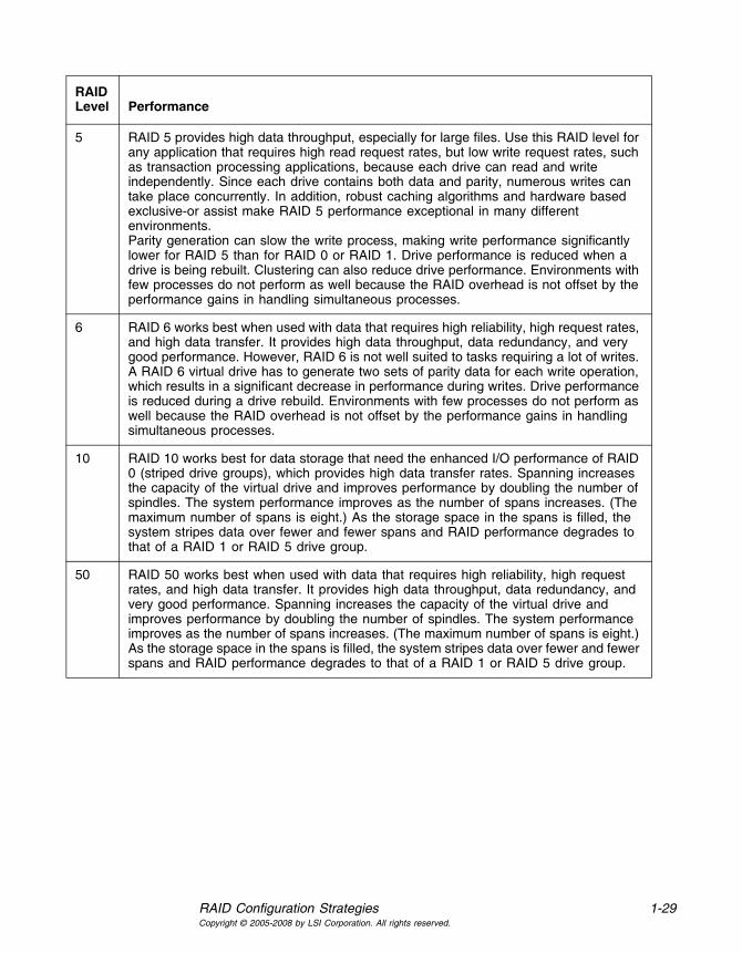
Table 1.13 RAID Levels and Performance
6 Combines distributed parity with disk striping. RAID 6 can sustain two drive failures and still maintain data integrity. Parity provides redundancy for two drive failures without duplicating the contents of entire drives. If a drive fails, the RAID controller uses the parity data to reconstruct all missing information. In RAID 6, this method is applied to entire drives or stripes across all of the drives in a drive group. Using distributed partiy, RAID 6 offers fault tolerance with limited overhead.
10 Provides complete data redundancy using striping across spanned RAID 1 drive groups. RAID 10 works well for any environment that requires the 100 percent redundancy offered by mirrored drive groups. RAID 10 can sustain a drive failure in each mirrored drive group and maintain drive integrity.
50 Provides data redundancy using distributed parity across spanned RAID 5 drive groups. RAID 50 includes both parity and disk striping across multiple drives. If a drive fails, the RAID controller uses the parity data to recreate all missing information. RAID 50 can sustain one drive failure per RAID 5 drive group and still maintain data integrity.
60 Provides data redundancy using distributed parity across spanned RAID 6 drive groups. RAID 60 can sustain two drive failures per RAID 6 drive group and still maintain data integrity. It provides the highest level of protection against drive failures of all of the RAID levels. RAID 60 includes both parity and disk striping across multiple drives. If a drive fails, the RAID controller uses the parity data to recreate all missing information.
RAID Level Fault Tolerance
RAID Level Performance
0 RAID 0 (striping) offers the best performance of any RAID level. RAID 0 breaks up data into smaller blocks, then writes a block to each drive in the drive group. Disk striping writes data across multiple drives instead of just one drive. It involves partitioning each drive storage space into stripes that can vary in size from 8 KB to 1024 KB. These stripes are interleaved in a repeated sequential manner. Disk striping enhances performance because multiple drives are accessed simultaneously.
1 With RAID 1 (mirroring), each drive in the system must be duplicated, which requires more time and resources than striping. Performance is impaired during drive rebuilds.
RAID Configuration Strategies 1-29Copyright © 2005-2008 by LSI Corporation. All rights reserved.
5 RAID 5 provides high data throughput, especially for large files. Use this RAID level for any application that requires high read request rates, but low write request rates, such as transaction processing applications, because each drive can read and write independently. Since each drive contains both data and parity, numerous writes can take place concurrently. In addition, robust caching algorithms and hardware based exclusive-or assist make RAID 5 performance exceptional in many different environments. Parity generation can slow the write process, making write performance significantly lower for RAID 5 than for RAID 0 or RAID 1. Drive performance is reduced when a drive is being rebuilt. Clustering can also reduce drive performance. Environments with few processes do not perform as well because the RAID overhead is not offset by the performance gains in handling simultaneous processes.
6 RAID 6 works best when used with data that requires high reliability, high request rates, and high data transfer. It provides high data throughput, data redundancy, and very good performance. However, RAID 6 is not well suited to tasks requiring a lot of writes. A RAID 6 virtual drive has to generate two sets of parity data for each write operation, which results in a significant decrease in performance during writes. Drive performance is reduced during a drive rebuild. Environments with few processes do not perform as well because the RAID overhead is not offset by the performance gains in handling simultaneous processes.
10 RAID 10 works best for data storage that need the enhanced I/O performance of RAID 0 (striped drive groups), which provides high data transfer rates. Spanning increases the capacity of the virtual drive and improves performance by doubling the number of spindles. The system performance improves as the number of spans increases. (The maximum number of spans is eight.) As the storage space in the spans is filled, the system stripes data over fewer and fewer spans and RAID performance degrades to that of a RAID 1 or RAID 5 drive group.
50 RAID 50 works best when used with data that requires high reliability, high request rates, and high data transfer. It provides high data throughput, data redundancy, and very good performance. Spanning increases the capacity of the virtual drive and improves performance by doubling the number of spindles. The system performance improves as the number of spans increases. (The maximum number of spans is eight.) As the storage space in the spans is filled, the system stripes data over fewer and fewer spans and RAID performance degrades to that of a RAID 1 or RAID 5 drive group.
RAID Level Performance

1-30 Introduction to RAIDCopyright © 2005-2008 by LSI Corporation. All rights reserved.
1.6.3 Maximizing Storage Capacity
Storage capacity is an important factor when selecting a RAID level. There are several variables to consider. Striping alone (RAID 0) requires less storage space than mirrored data (RAID 1) or distributed parity (RAID 5 or RAID 6). RAID 5, which provides redundancy for one drive failure without duplicating the contents of entire drives, requires less space then RAID 1. Table 1.14 explains the effects of the RAID levels on storage capacity.
Table 1.14 RAID Levels and Capacity
60 RAID 60 works best when used with data that requires high reliability, high request rates, and high data transfer. It provides high data throughput, data redundancy, and very good performance. Spanning increases the capacity of the virtual drive and improves performance by doubling the number of spindles. The system performance improves as the number of spans increases. (The maximum number of spans is eight.) As the storage space in the spans is filled, the system stripes data over fewer and fewer spans and RAID performance degrades to that of a RAID 1 or RAID 6 drive group.
RAID 60 is not well suited to tasks requiring a lot of writes. A RAID 60 virtual drive has to generate two sets of parity data for each write operation, which results in a significant decrease in performance during writes. Drive performance is reduced during a drive rebuild. Environments with few processes do not perform as well because the RAID overhead is not offset by the performance gains in handling simultaneous processes.
RAID Level Performance
RAID Level Capacity
0 RAID 0 (disk striping) involves partitioning each drive storage space into stripes that can vary in size. The combined storage space is composed of stripes from each drive. RAID 0 provides maximum storage capacity for a given set of drives.
1 With RAID 1 (mirroring), data written to one drive is simultaneously written to another drive, which doubles the required data storage capacity. This is expensive because each drive in the system must be duplicated.
5 RAID 5 provides redundancy for one drive failure without duplicating the contents of entire drives. RAID 5 breaks up data into smaller blocks, calculates parity by performing an exclusive-or on the blocks, then writes the blocks of data and parity to each drive in the drive group. The size of each block is determined by the stripe size parameter, which is set during the creation of the RAID set.

RAID Availability 1-31Copyright © 2005-2008 by LSI Corporation. All rights reserved.
1.7 RAID Availability
1.7.1 RAID Availability Concept
Data availability without downtime is essential for many types of data processing and storage systems. Businesses want to avoid the financial costs and customer frustration associated with failed servers. RAID helps you maintain data availability and avoid downtime for the servers that provide that data. RAID offers several features, such as spare drives and rebuilds, that you can use to fix any drive problems, while keeping the servers running and data available. The following subsections describe these features.
1.7.1.1 Spare Drives
You can use spare drives to replace failed or defective drives in a drive group. A replacement drive must be at least as large as the drive it replaces. Spare drives include hot swaps, hot spares, and cold swaps.
A hot swap is the manual substitution of a replacement unit in a disk subsystem for a defective one, where the substitution can be performed while the subsystem is running (performing its normal functions). The
6 RAID 6 provides redundancy for two drive failures without duplicating the contents of entire drives. However, it requires extra capacity because it uses two parity blocks per stripe. This makes RAID 60 more expensive to implement.
10 RAID 10 requires twice as many drives as all other RAID levels except RAID 1. RAID 10 works well for medium-sized databases or any environment that requires a higher degree of fault tolerance and moderate to medium capacity. Disk spanning allows multiple drives to function like one big drive. Spanning overcomes lack of disk space and simplifies storage management by combining existing resources or adding relatively inexpensive resources.
50 RAID 50 requires two to four times as many parity drives as RAID 5. This RAID level works best when used with data that requires medium to large capacity.
60 RAID 60 provides redundancy for two drive failures in each RAID set without duplicating the contents of entire drives. However, it requires extra capacity because a RAID 60 virtual drive has to generate two sets of parity data for each write operation. This makes RAID 60 more expensive to implement.
RAID Level Capacity

1-32 Introduction to RAIDCopyright © 2005-2008 by LSI Corporation. All rights reserved.
backplane and enclosure must support hot swap in order for the functionality to work.
Hot spare drives are drives that power up along with the RAID drives and operate in a standby state. If a drive used in a RAID virtual drive fails, a hot spare automatically takes its place and the data on the failed drive is rebuilt on the hot spare. Hot spares can be used for RAID levels 1, 5, 6, 10, 50, and 60.
Note: If a rebuild to a hot spare fails for any reason, the hot spare drive will be marked as "failed." If the source drive fails, both the source drive and the hot spare drive will be marked as "failed."
A cold swap requires that you power down the system before replacing a defective drive in a disk subsystem.
1.7.1.2 Rebuilding
If a drive fails in a drive group that is configured as a RAID 1, 5, 6, 10, 50, or 60 virtual drive, you can recover the lost data by rebuilding the drive. If you have configured hot spares, the RAID controller automatically tries to use them to rebuild failed drives. Manual rebuild is necessary if no hot spares with enough capacity to rebuild the failed drives are available.You must insert a drive with enough storage into the subsystem before rebuilding the failed drive.
1.8 Configuration Planning
Factors to consider when planning a configuration are the number of drives the RAID controller can support, the purpose of the drive group, and the availability of spare drives.
Each type of data stored in the disk subsystem has a different frequency of read and write activity. If you know the data access requirements, you can more successfully determine a strategy for optimizing the disk subsystem capacity, availability, and performance.
Servers that support video on demand typically read the data often, but write data infrequently. Both the read and write operations tend to be

Configuration Planning 1-33Copyright © 2005-2008 by LSI Corporation. All rights reserved.
long. Data stored on a general-purpose file server involves relatively short read and write operations with relatively small files.
1.8.1 Number of Drives
Your configuration planning for the SAS RAID controller depends in part on the number of drives that you want to use in a RAID drive group. The number of drives in a drive group determines the RAID levels that can be supported. Only one RAID level can be assigned to each virtual drive.
1.8.2 Drive Group Purpose
Important factors to consider when creating RAID drive groups include availability, performance, and capacity. Define the major purpose of the drive group by answering questions related to these factors, such as the following, which are followed by suggested RAID levels for each situation:
• Will this drive group increase the system storage capacity for general-purpose file and print servers? Use RAID 5, 6, 10, 50, or 60.
• Does this drive group support any software system that must be available 24 hours per day? Use RAID 1, 5, 6, 10, 50, or 60.
• Will the information stored in this drive group contain large audio or video files that must be available on demand? Use RAID 0.
• Will this drive group contain data from an imaging system? Use RAID 0 or 10.
Fill out Table 1.15 to help you plan the drive group configuration. Rank the requirements for your drive group, such as storage space and data redundancy, in order of importance, and then review the suggested RAID levels.
Table 1.15 Factors to Consider for Drive Group Configuration
Requirement Rank Suggested RAID Level(s)
Storage space RAID 0, RAID 5
Data redundancy RAID 5, RAID 6, RAID 10, RAID 50, RAID 60
Drive performance and throughput RAID 0, RAID 10

1-34 Introduction to RAIDCopyright © 2005-2008 by LSI Corporation. All rights reserved.
Hot spares (extra drives required) RAID 1, RAID 5, RAID 6, RAID 10, RAID 50, RAID 60
Table 1.15 Factors to Consider for Drive Group Configuration (Cont.)
Requirement Rank Suggested RAID Level(s)
MegaRAID SAS Software User’s Guide 2-1Copyright © 2005-2008 by LSI Corporation. All rights reserved.
Chapter 2WebBIOS Configuration Utility
This chapter describes the WebBIOS Configuration Utility (CU) and consists of the following sections:
• Section 2.1, “Overview”
• Section 2.2, “Starting the WebBIOS CU”
• Section 2.3, “WebBIOS CU Main Screen Options”
• Section 2.4, “Creating a Storage Configuration”
• Section 2.5, “Viewing and Changing Device Properties”
• Section 2.6, “Viewing System Event Information”
• Section 2.7, “Managing Configurations”
2.1 Overview
The WebBIOS CU enables you to create and manage RAID configurations on LSI SAS controllers. Unlike the MegaRAID Storage Manager™ software, the WebBIOS CU resides in the SAS controller BIOS and operates independently of the operating system.
You can use the WebBIOS CU to do the following tasks:
• Create drive groups and virtual drives for storage configurations
• Delete virtual drives
• Migrate a storage configuration to a different RAID level
• Detect configuration mismatches
• Import a foreign configuration (see Section 2.7.3, “Importing or Clearing a Foreign Configuration”)

2-2 WebBIOS Configuration UtilityCopyright © 2005-2008 by LSI Corporation. All rights reserved.
• Display controller, virtual drive, drive, and battery backup unit (BBU) properties
• Scan devices connected to the controller
• Initialize virtual drives
• Check configurations for data consistency
The WebBIOS CU provides a configuration wizard to guide you through the configuration of virtual drives and drive groups.
2.2 Starting the WebBIOS CU
Follow these steps to start the WebBIOS CU and access the main screen.
1. When the host computer is booting, hold down the <Ctrl> key and press the <H> key when the following text appears on the screen:
Copyright© LSI CorporationPress <Ctrl><H> for WebBIOS
The Adapter Selection screen appears.
2. If the system has multiple SAS controllers, select a controller.
3. Click Start to continue.
The main WebBIOS CU screen appears.

WebBIOS CU Main Screen Options 2-3Copyright © 2005-2008 by LSI Corporation. All rights reserved.
2.3 WebBIOS CU Main Screen Options
Figure 2.1 shows the screen that appears when you start the WebBIOS CU and select a controller.
Figure 2.1 WebBIOS CU Main Screen
In the lower right panel, the logical view part of the screen displays all of the virtual drives that are configured on this controller. In the upper right panel, the physical view part of the screen displays the drives that are connected to the controller.
To toggle between the physical view and logical view of the storage devices connected to the controller, click Physical View or Logical View in the menu on the left. When the physical view screen is displayed, the lower right panel displays the drive groups that are configured on this controller.
For drives in an enclosure, the screen displays the drive information in the following format: (Connector): position: slot. The connector information identifies where the chain of enclosures is connected to the

2-4 WebBIOS Configuration UtilityCopyright © 2005-2008 by LSI Corporation. All rights reserved.
RAID controller. The position number identifies the position of the enclosure in the daisy chain.
Directly-attached drives displays in the following format: Slot.
The toolbar at the top of the WebBIOS CU has the following buttons, as listed in Table 2.1.
Here is a description of the options listed on the left of the main WebBIOS CU screen:
• Adapter Properties: Select this to view the properties of the currently selected SAS controller. For more information, see Section 2.5.1, “Viewing and Changing Controller Properties.”
• Scan Devices: Select this to have the WebBIOS CU re-scan the physical and virtual drives for any changes in the drive status or the physical configuration. The WebBIOS CU displays the results of the scan in the physical and virtual drive descriptions.
Table 2.1 WebBIOS CU Toolbar Icons
Icon Description
Click this icon to return to the main screen from any other WebBIOS CU screen.
Click this icon to return to the previous screen that you were viewing.
Click this icon to exit the WebBIOS CU program.
Click this icon to display the Adapter Selection screen. If the computer system has multiple controllers, you use this screen to view the devices connected to a different controller.
Click this icon to turn off the sound on the onboard controller alarm.
Click this icon to display information about the WebBIOS CU version, browser version, and HTML interface engine.

Creating a Storage Configuration 2-5Copyright © 2005-2008 by LSI Corporation. All rights reserved.
• Virtual Drives: Select this to view the Virtual Disks screen, where you can change and view virtual drive properties, delete virtual drives, initialize drives, and perform other tasks. For more information, see Section 2.5.2, “Viewing and Changing Virtual Drive Properties.”
• Drives: Select this to view the Drives screen, where you can view drive properties, create hot spares, and perform other tasks. For more information, see Section 2.5.3, “Viewing Drive Properties.”
• Configuration Wizard: Select this to start the Configuration Wizard and create a new storage configuration, clear a configuration, or add a configuration. For more information, see Section 2.4, “Creating a Storage Configuration.”
• Adapter Selection: Select this to view the Adapter Selection screen, where you can select a different SAS controller. You can then view information about the controller and the devices connected to it, or create a new configuration on the controller.
• Physical View/Logical View: Select this to toggle between the Physical View and Logical View screens.
• Events: Select this to view system events in the Event Information screen. For more information, see Section 2.6, “Viewing System Event Information.”
• Exit: Select this to exit the WebBIOS CU and continue with system boot.
2.4 Creating a Storage Configuration
This section explains how to use the WebBIOS CU Configuration Wizard to configure RAID drive groups and virtual drives. The following subsections explain how to use the Configuration Wizard to create storage configurations:
• Section 2.4.1, “Selecting the Configuration with the Configuration Wizard”
• Section 2.4.2, “Using Auto Configuration”
• Section 2.4.3, “Using Custom Configuration”
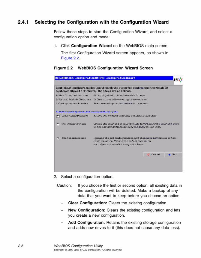
2-6 WebBIOS Configuration UtilityCopyright © 2005-2008 by LSI Corporation. All rights reserved.
2.4.1 Selecting the Configuration with the Configuration Wizard
Follow these steps to start the Configuration Wizard, and select a configuration option and mode:
1. Click Configuration Wizard on the WebBIOS main screen.
The first Configuration Wizard screen appears, as shown in Figure 2.2.
Figure 2.2 WebBIOS Configuration Wizard Screen
2. Select a configuration option.
Caution: If you choose the first or second option, all existing data in the configuration will be deleted. Make a backup of any data that you want to keep before you choose an option.
– Clear Configuration: Clears the existing configuration.
– New Configuration: Clears the existing configuration and lets you create a new configuration.
– Add Configuration: Retains the existing storage configuration and adds new drives to it (this does not cause any data loss).

Creating a Storage Configuration 2-7Copyright © 2005-2008 by LSI Corporation. All rights reserved.
3. Click Next.
A dialog box warns that you will lose data if you select Clear Configuration or New Configuration.
4. On the next screen, select a configuration mode:
– Custom Configuration: Allows you to control all attributes of the new storage configuration.
– Auto Configuration with Redundancy: Automatically creates an optimal RAID 1, RAID 5, or RAID 6 configuration, providing data redundancy.
– Auto Configuration without Redundancy: Automatically creates a non-redundant RAID 0 configuration.
5. Click Next to continue.
If you select one of the Auto Configuration options, continue with Section 2.4.2, “Using Auto Configuration.” If you select Custom Configuration, continue with Section 2.4.3, “Using Custom Configuration.”
2.4.2 Using Auto Configuration
Follow these instructions to create a configuration with auto configuration, either with or without redundancy:
1. When WebBIOS displays the proposed new configuration, review the information on the screen, and click Accept to accept it. (Or click Back to go back and change the configuration.)
– RAID 0: If you select Auto Configuration without Redundancy, WebBIOS creates a RAID 0 configuration.
– RAID 1: If you select Auto Configuration with Redundancy, and only two drives are available, WebBIOS creates a RAID 1 configuration.
– RAID 5: If you select Auto Configuration with Redundancy, and three or more drives are available, WebBIOS creates a RAID 5 configuration.
– RAID 6: If you select Auto Configuration with Redundancy, and the RAID 6 option is enabled, and three or more drives are available, WebBIOS creates a RAID 6 configuration.
2. Click Yes when you are prompted to save the configuration.

2-8 WebBIOS Configuration UtilityCopyright © 2005-2008 by LSI Corporation. All rights reserved.
3. Click Yes when you are prompted to initialize the new virtual drive(s).
WebBIOS CU begins a background initialization of the virtual drives.
2.4.3 Using Custom Configuration
The following subsections describe the procedures for creating RAID drive groups for RAID levels 0, 1, 5, 6, 10, 50, and 60:
• Section 2.4.3.1, “Using Custom Configuration: RAID 0”
• Section 2.4.3.2, “Using Custom Configuration: RAID 1”
• Section 2.4.3.3, “Using Custom Configuration: RAID 5”
• Section 2.4.3.4, “Using Custom Configuration: RAID 6”
• Section 2.4.3.5, “Using Custom Configuration: RAID 10”
• Section 2.4.3.6, “Using Custom Configuration: RAID 50”
• Section 2.4.3.7, “Using Custom Configuration: RAID 60”
2.4.3.1 Using Custom Configuration: RAID 0
RAID 0 provides drive striping across all drives in the RAID drive group. RAID 0 does not provide any data redundancy but does offer the best performance of any RAID level. RAID 0 is ideal for applications that require high bandwidth but do not require fault tolerance. RAID 0 also denotes an independent or single drive.
Note: RAID level 0 is not fault-tolerant. If a drive in a RAID 0 drive group fails, the whole virtual drive (all drives associated with the virtual drive) fails.
When you select Custom Configuration and click Next, the drive group Definition screen appears. You use this screen to select drives to create drive groups.
1. Hold <Ctrl> while selecting two or more ready drives in the Drives panel on the left until you have selected all desired drives for the drive group.
2. Click AddtoArray to move the drives to a proposed drive group configuration in the Disk Groups panel on the right, as shown in Figure 2.3.
If you need to undo the changes, click the Reclaim button.

Creating a Storage Configuration 2-9Copyright © 2005-2008 by LSI Corporation. All rights reserved.
Figure 2.3 WebBIOS Disk Group Definition Screen
3. When you have finished selecting drives for the drive group, click Accept DG.
4. Click Next.
The Virtual Disk Definition screen appears, as shown in Figure 2.4. This screen lists the possible RAID levels for the drive group. Use this screen to select the RAID level, stripe size, read policy, and other attributes for the new virtual drives.

2-10 WebBIOS Configuration UtilityCopyright © 2005-2008 by LSI Corporation. All rights reserved.
Figure 2.4 WebBIOS Virtual Disk Definition Screen
5. Change the virtual drive options from the defaults listed on the screen as needed.
Here are brief explanations of the virtual drive options:
• RAID Level: The drop-down menu lists the possible RAID levels for the virtual drive. Select RAID 0.
• Stripe Size: The stripe size specifies the length of the data segments that the RAID controller writes across multiple drives, not including parity drives. For example, consider a stripe that contains 64 KB of drive space and has 16 KB of data residing on each drive in the stripe. In this case, the stripe size is 64 KB and the strip size is 16 KB. You can set the stripe size to 8, 16, 32, 64, 128, 256, 512, and 1024 Kbytes. A larger stripe size produces higher read performance. If your computer regularly performs random read requests, choose a smaller stripe size. The default is 64 Kbytes.
• Access Policy: Select the type of data access that is allowed for this virtual drive:
◊ RW: Allow read/write access. This is the default.

Creating a Storage Configuration 2-11Copyright © 2005-2008 by LSI Corporation. All rights reserved.
◊ Read Only: Allow read-only access.
◊ Blocked: Do not allow access.
• Read Policy: Specify the read policy for this virtual drive:
◊ Normal: This disables the read ahead capability. This is the default.
◊ Ahead: This enables read ahead capability, which allows the controller to read sequentially ahead of requested data and to store the additional data in cache memory, anticipating that the data will be needed soon. This speeds up reads for sequential data, but there is little improvement when accessing random data.
◊ Adaptive: When Adaptive read ahead is selected, the controller begins using read ahead if the two most recent drive accesses occurred in sequential sectors. If the read requests are random, the controller reverts to Normal (no read ahead).
• Write Policy: Specify the write policy for this virtual drive:
◊ WBack: In Writeback mode the controller sends a data transfer completion signal to the host when the controller cache has received all of the data in a transaction. This setting is recommended in Standard mode.
◊ WThru: In Writethrough mode the controller sends a data transfer completion signal to the host when the drive subsystem has received all of the data in a transaction. This is the default.
◊ Bad BBU: Select this mode if you want the controller to use Writeback mode but the controller has no BBU or the BBU is bad. If you do not choose this option, the controller firmware automatically switches to Writethrough mode if it detects a bad or missing BBU.
Caution: LSI allows Writeback mode to be used with or without a battery. LSI recommends that you use either a battery to protect the controller cache, or an uninterruptible power supply (UPS) to protect the entire system. If you do not use a battery or a UPS, and there is a power failure, you risk losing the data in the controller cache.

2-12 WebBIOS Configuration UtilityCopyright © 2005-2008 by LSI Corporation. All rights reserved.
• IO Policy: The IO Policy applies to reads on a specific virtual drive. It does not affect the read ahead cache.
◊ Direct: In direct I/O mode, reads are not buffered in cache memory. Data is transferred to the cache and the host concurrently. If the same data block is read again, it comes from cache memory. This is the default.
◊ Cached: In cached I/O mode, all reads are buffered in cache memory.
• Disk Cache Policy: Specify the drive cache policy:
◊ Enable: Enable the drive cache.
◊ Disable: Disable the drive cache. This is the default.
◊ Unchanged: Leave the current drive cache policy unchanged.
• Disable BGI: Specify the background initialization status:
◊ No: Leave background initialization enabled. This means that a new configuration can be initialized in the background while you use WebBIOS to do other configuration tasks. This is the default.
◊ Yes: Select Yes if you do not want to allow background initializations for configurations on this controller.
• Select Size: Specify the size of the virtual drive in megabytes. Normally, this would be the full size for RAID 0 shown in the Configuration panel on the right. You may specify a smaller size if you want to create other virtual drives on the same drive group.
6. Click Accept to accept the changes to the virtual drive definition, or click Reclaim to return to the previous settings.
7. Click Next when you are finished defining virtual drives.
The Configuration Preview screen appears, as shown in Figure 2.5.

Creating a Storage Configuration 2-13Copyright © 2005-2008 by LSI Corporation. All rights reserved.
Figure 2.5 RAID 0 Configuration Preview
8. Check the information in the configuration preview.
9. If the virtual drive configuration is acceptable, click Accept to save the configuration. Otherwise, click Cancel to end the operation and return to the WebBIOS main menu, or click Back to return to the previous screens and change the configuration.
10. If you accept the configuration, click Yes at the prompt to save the configuration.
The WebBIOS main menu appears.
2.4.3.2 Using Custom Configuration: RAID 1
In RAID 1, the RAID controller duplicates all data from one drive to a second drive. RAID 1 provides complete data redundancy, but at the cost of doubling the required data storage capacity. It is appropriate for small databases or any other environment that requires fault tolerance but small capacity.

2-14 WebBIOS Configuration UtilityCopyright © 2005-2008 by LSI Corporation. All rights reserved.
When you select Custom Configuration and click Next, the Disk Group Definition screen appears. You use this screen to select drives to create drive groups.
1. Hold <Ctrl> while you select two ready drives in the Drives panel on the left. You must select an even number of drives.
2. Click AddtoArray to move the drives to a proposed drive group configuration in the Disk Groups panel on the right, as shown in Figure 2.6.
If you need to undo the changes, click the Reclaim button.
Note: A RAID 1 virtual drive can contain up to 16 drive groups and 32 drives in a single span. (Other factors, such as the type of controller, can limit the number of drives.) You must use two drives in each RAID 1 drive group in the span.
Figure 2.6 WebBIOS Disk Group Definition Screen
3. When you have finished selecting drives for the drive group, click Accept DG.
4. Click Next.

Creating a Storage Configuration 2-15Copyright © 2005-2008 by LSI Corporation. All rights reserved.
The Virtual Disk Definition screen appears, as shown in Figure 2.7. You use this screen to select the RAID level, stripe size, read policy, and other attributes for the new virtual drives.
Figure 2.7 WebBIOS Virtual Disk Definition Screen
5. Change the virtual drive options from the defaults listed on the screen as needed.
Here are brief explanations of the virtual drive options:
• RAID Level: The drop-down menu lists the possible RAID levels for the virtual drive. Select RAID 1.
• Stripe Size: The stripe size specifies the length of the data segments that the RAID controller writes across multiple drives, not including parity drives. For example, consider a stripe that contains 64 KB of drive space and has 16 KB of data residing on each drive in the stripe. In this case, the stripe size is 64 KB and the strip size is 16 KB. You can set the stripe size to 8, 16, 32, 64, 128, 256, 512, and 1024 Kbytes. A larger stripe size produces higher read performance. If your computer regularly performs random read requests, choose a smaller stripe size. The default is 64 Kbytes.

2-16 WebBIOS Configuration UtilityCopyright © 2005-2008 by LSI Corporation. All rights reserved.
• Access Policy: Select the type of data access that is allowed for this virtual drive:
◊ RW: Allow read/write access. This is the default.
◊ Read Only: Allow read-only access.
◊ Blocked: Do not allow access.
• Read Policy: Specify the read policy for this virtual drive:
◊ Normal: This disables the read ahead capability. This is the default.
◊ Ahead: This enables read ahead capability, which allows the controller to read sequentially ahead of requested data and to store the additional data in cache memory, anticipating that the data will be needed soon. This speeds up reads for sequential data, but there is little improvement when accessing random data.
◊ Adaptive: When Adaptive read ahead is selected, the controller begins using read ahead if the two most recent drive accesses occurred in sequential sectors. If the read requests are random, the controller reverts to Normal (no read ahead).
• Write Policy: Specify the write policy for this virtual drive:
◊ WBack: In Writeback mode the controller sends a data transfer completion signal to the host when the controller cache has received all of the data in a transaction. This setting is recommended in Standard mode.
◊ WThru: In Writethrough mode the controller sends a data transfer completion signal to the host when the drive subsystem has received all of the data in a transaction. This is the default.
◊ Bad BBU: Select this mode if you want the controller to use Writeback mode but the controller has no BBU or the BBU is bad. If you do not choose this option, the controller firmware automatically switches to Writethrough mode if it detects a bad or missing BBU.
Caution: LSI allows Writeback mode to be used with or without a battery. LSI recommends that you use either a battery to protect the controller cache, or an uninterruptible power

Creating a Storage Configuration 2-17Copyright © 2005-2008 by LSI Corporation. All rights reserved.
supply (UPS) to protect the entire system. If you do not use a battery or a UPS, and there is a power failure, you risk losing the data in the controller cache.
• IO Policy: The IO Policy applies to reads on a specific virtual drive. It does not affect the read ahead cache.
◊ Direct: In Direct I/O mode, reads are not buffered in cache memory. Data is transferred to the cache and the host concurrently. If the same data block is read again, it comes from cache memory. This is the default.
◊ Cached: In Cached I/O mode, all reads are buffered in cache memory.
– Disk Cache Policy: Specify the drive cache policy:
◊ Enable: Enable the drive cache.
◊ Disable: Disable the drive cache. This is the default.
◊ Unchanged: Leave the current drive cache policy unchanged.
• Disable BGI: Specify the background initialization status:
◊ No: Leave background initialization enabled. This means that a new configuration can be initialized in the background while you use WebBIOS to do other configuration tasks. This is the default.
◊ Yes: Select Yes if you do not want to allow background initializations for configurations on this controller.
• Select Size: Specify the size of the virtual drive(s) in megabytes. Normally, this would be the full size for RAID 1 shown in the Configuration panel on the right. You may specify a smaller size if you want to create other virtual drives on the same drive group.
6. Click Accept to accept the changes to the virtual drive definition, or click Reclaim to return to the previous settings.
7. Click Next when you are finished defining virtual drives.
The Configuration Preview screen appears, as shown in Figure 2.8.

2-18 WebBIOS Configuration UtilityCopyright © 2005-2008 by LSI Corporation. All rights reserved.
Figure 2.8 RAID 1 Configuration Preview
8. Check the information in the configuration preview.
9. If the virtual drive configuration is acceptable, click Accept to save the configuration. Otherwise, click Cancel to end the operation and return to the WebBIOS main menu, or click Back to return to the previous screens and change the configuration.
10. If you accept the configuration, click Yes at the prompt to save the configuration.
The WebBIOS main menu appears.
2.4.3.3 Using Custom Configuration: RAID 5
RAID 5 uses drive striping at the block level and parity. In RAID 5, the parity information is written to all drives. It is best suited for networks that perform a lot of small input/output (I/O) transactions simultaneously. RAID 5 provides data redundancy, high read rates, and good performance in most environments. It also provides redundancy with lowest loss of capacity.

Creating a Storage Configuration 2-19Copyright © 2005-2008 by LSI Corporation. All rights reserved.
RAID 5 provides high data throughput. RAID 5 is useful for transaction processing applications because each drive can read and write independently. If a drive fails, the RAID controller uses the parity drive to recreate all missing information. You can use RAID 5 for office automation and online customer service that require fault tolerance. In addition, RAID 5 is good for any application that has high read request rates but low write request rates.
When you select Custom Configuration and click Next, the Disk Group Definition screen appears. You use this screen to select drives to create drive groups.
1. Hold <Ctrl> while you select at least three ready drives in the Physical Drives panel on the left.
2. Click AddtoArray to move the drives to a proposed drive group configuration in the Disk Groups panel on the right, as shown in Figure 2.9.
If you need to undo the changes, click the Reclaim button.
Figure 2.9 WebBIOS Disk Group Definition Screen

2-20 WebBIOS Configuration UtilityCopyright © 2005-2008 by LSI Corporation. All rights reserved.
3. When you have finished selecting drives for the drive group, click Accept DG.
4. Click Next.
The Virtual Disk Definition screen appears, as shown in Figure 2.10. You use this screen to select the RAID level, stripe size, read policy, and other attributes for the new virtual drives.
Figure 2.10 WebBIOS Virtual Disk Definition Screenf
5. Change the virtual drive options from the defaults listed on the screen as needed.
Here are brief explanations of the virtual drive options:
• RAID Level: The drop-down menu lists the possible RAID levels for the virtual drive. Select RAID 5.
• Stripe Size: The stripe size specifies the length of the data segments that the RAID controller writes across multiple drives, not including parity drives. For example, consider a stripe that contains 64 KB of drive space and has 16 KB of data residing on each drive in the stripe. In this case, the stripe size is 64 KB and the strip size is 16 KB. You can set the stripe size to 8, 16, 32, 64, 128, 256, 512,

Creating a Storage Configuration 2-21Copyright © 2005-2008 by LSI Corporation. All rights reserved.
and 1024 Kbytes. A larger stripe size produces higher read performance. If your computer regularly performs random read requests, choose a smaller stripe size. The default is 64 Kbytes.
• Access Policy: Select the type of data access that is allowed for this virtual drive:
◊ RW: Allow read/write access. This is the default.
◊ Read Only: Allow read-only access.
◊ Blocked: Do not allow access.
• Read Policy: Specify the read policy for this virtual drive:
◊ Normal: This disables the read ahead capability. This is the default.
◊ Ahead: This enables read ahead capability, which allows the controller to read sequentially ahead of requested data and to store the additional data in cache memory, anticipating that the data will be needed soon. This speeds up reads for sequential data, but there is little improvement when accessing random data.
◊ Adaptive: When Adaptive read ahead is selected, the controller begins using read ahead if the two most recent drive accesses occurred in sequential sectors. If the read requests are random, the controller reverts to Normal (no read ahead).
• Write Policy: Specify the write policy for this virtual drive:
◊ WBack: In Writeback mode the controller sends a data transfer completion signal to the host when the controller cache has received all of the data in a transaction. This setting is recommended in Standard mode.
◊ WThru: In Writethrough mode the controller sends a data transfer completion signal to the host when the drive subsystem has received all of the data in a transaction. This is the default.
◊ Bad BBU: Select this mode if you want the controller to use Writeback mode but the controller has no BBU or the BBU is bad. If you do not choose this option, the controller firmware automatically switches to Writethrough mode if it detects a bad or missing BBU.

2-22 WebBIOS Configuration UtilityCopyright © 2005-2008 by LSI Corporation. All rights reserved.
Caution: LSI allows Writeback mode to be used with or without a battery. LSI recommends that you use either a battery to protect the controller cache, or an uninterruptible power supply (UPS) to protect the entire system. If you do not use a battery or a UPS, and there is a power failure, you risk losing the data in the controller cache.
• IO Policy: The IO Policy applies to reads on a specific virtual drive. It does not affect the read ahead cache.
◊ Direct: In Direct I/O mode, reads are not buffered in cache memory. Data is transferred to the cache and the host concurrently. If the same data block is read again, it comes from cache memory. This is the default.
◊ Cached: In Cached I/O mode, all reads are buffered in cache memory.
• Disk Cache Policy: Specify the drive cache policy:
◊ Enable: Enable the drive cache.
◊ Disable: Disable the drive cache. This is the default.
◊ Unchanged: Leave the current drive cache policy unchanged.
• Disable BGI: Specify the background initialization status:
◊ No: Leave background initialization enabled. This means that a new configuration can be initialized in the background while you use WebBIOS to do other configuration tasks. This is the default.
◊ Yes: Select Yes if you do not want to allow background initializations for configurations on this controller.
• Select Size: Specify the size of the virtual drive in megabytes. Normally, this would be the full size for RAID 5 shown in the Configuration panel on the right. You may specify a smaller size if you want to create other virtual drives on the same drive group.
6. Click Accept to accept the changes to the virtual drive definition, or click Reclaim to return to the previous settings.
7. Click Next when you are finished defining virtual drives.
The Configuration Preview screen appears, as shown in Figure 2.11.

Creating a Storage Configuration 2-23Copyright © 2005-2008 by LSI Corporation. All rights reserved.
Figure 2.11 RAID 5 Configuration Preview
8. Check the information in the configuration preview.
9. If the virtual drive configuration is acceptable, click Accept to save the configuration. Otherwise, click Cancel to end the operation and return to the WebBIOS main menu, or click Back to return to the previous screens and change the configuration.
10. If you accept the configuration, click Yes at the prompt to save the configuration.
The WebBIOS main menu appears.
2.4.3.4 Using Custom Configuration: RAID 6
RAID 6 is similar to RAID 5 (drive striping and distributed parity), except that instead of one parity block per stripe, there are two. With two independent parity blocks, RAID 6 can survive the loss of two drives in a virtual drive without losing data. Use RAID 6 for data that requires a very high level of protection from loss.

2-24 WebBIOS Configuration UtilityCopyright © 2005-2008 by LSI Corporation. All rights reserved.
RAID 6 is best suited for networks that perform a lot of small input/output (I/O) transactions simultaneously. It provides data redundancy, high read rates, and good performance in most environments.
In the case of a failure of one drive or two drives in a virtual drive, the RAID controller uses the parity blocks to recreate all of the missing information. If two drives in a RAID 6 virtual drive fail, two drive rebuilds are required, one for each drive. These rebuilds do not occur at the same time. The controller rebuilds one failed drive, and then the other failed drive.
When you select Custom Configuration and click Next, the drive Group Definition screen appears. You use this screen to select drives to create drive groups.
1. Hold <Ctrl> while selecting at least three ready drives in the Drives panel on the left.
2. Click AddtoArray to move the drives to a proposed drive group configuration in the Disk Groups panel on the right, as shown in Figure 2.9.
If you need to undo the changes, click the Reclaim button.

Creating a Storage Configuration 2-25Copyright © 2005-2008 by LSI Corporation. All rights reserved.
Figure 2.12 WebBIOS Disk Group Definition Screen
3. When you have finished selecting drives for the drive group, click Accept DG for each.
4. Click Next.
The Virtual Disk Definition screen appears, as shown in Figure 2.13. Use this screen to select the RAID level, stripe size, read policy, and other attributes for the new virtual drives.

2-26 WebBIOS Configuration UtilityCopyright © 2005-2008 by LSI Corporation. All rights reserved.
Figure 2.13 WebBIOS Virtual Disk Definition Screen
5. Change the virtual drive options from the defaults listed on the screen as needed.
Here are brief explanations of the virtual drive options:
• RAID Level: The drop-down menu lists the possible RAID levels for the virtual drive. Select RAID 6.
• Stripe Size: The stripe size specifies the length of the data segments that the RAID controller writes across multiple drives, not including parity drives. For example, consider a stripe that contains 64 KB of drive space and has 16 KB of data residing on each drive in the stripe. In this case, the stripe size is 64 KB and the strip size is 16 KB. You can set the stripe size to 8, 16, 32, 64, 128, 256, 512, and 1024 Kbytes. A larger stripe size produces higher read performance. If your computer regularly performs random read requests, choose a smaller stripe size. The default is 64 Kbytes.
Note: WebBIOS does not not allow you to select 8 Kbytes as the stripe size when you create a RAID 6 drive group with three drives.

Creating a Storage Configuration 2-27Copyright © 2005-2008 by LSI Corporation. All rights reserved.
• Access Policy: Select the type of data access that is allowed for this virtual drive:
◊ RW: Allow read/write access. This is the default.
◊ Read Only: Allow read-only access.
◊ Blocked: Do not allow access.
• Read Policy: Specify the read policy for this virtual drive:
◊ Normal: This disables the read ahead capability. This is the default.
◊ Ahead: This enables read ahead capability, which allows the controller to read sequentially ahead of requested data and to store the additional data in cache memory, anticipating that the data will be needed soon. This speeds up reads for sequential data, but there is little improvement when accessing random data.
◊ Adaptive: When Adaptive read ahead is selected, the controller begins using read ahead if the two most recent drive accesses occurred in sequential sectors. If the read requests are random, the controller reverts to Normal (no read ahead).
• Write Policy: Specify the write policy for this virtual drive:
◊ WBack: In Writeback mode the controller sends a data transfer completion signal to the host when the controller cache has received all of the data in a transaction. This setting is recommended in Standard mode.
◊ WThru: In Writethrough mode the controller sends a data transfer completion signal to the host when the drive subsystem has received all of the data in a transaction. This is the default.
◊ Bad BBU: Select this mode if you want the controller to use Writeback mode but the controller has no BBU or the BBU is bad. If you do not choose this option, the controller firmware automatically switches to Writethrough mode if it detects a bad or missing BBU.
Caution: LSI allows Writeback mode to be used with or without a battery. LSI recommends that you use either a battery to protect the controller cache, or an uninterruptible power

2-28 WebBIOS Configuration UtilityCopyright © 2005-2008 by LSI Corporation. All rights reserved.
supply (UPS) to protect the entire system. If you do not use a battery or a UPS, and there is a power failure, you risk losing the data in the controller cache.
• IO Policy: The IO Policy applies to reads on a specific virtual drive. It does not affect the read ahead cache.
◊ Direct: In Direct I/O mode, reads are not buffered in cache memory. Data is transferred to the cache and the host concurrently. If the same data block is read again, it comes from cache memory. This is the default.
◊ Cached: In Cached I/O mode, all reads are buffered in cache memory.
• Disk Cache Policy: Specify the drive cache policy:
◊ Enable: Enable the drive cache.
◊ Disable: Disable the drive cache. This is the default.
◊ Unchanged: Leave the current drive cache policy unchanged.
• Disable BGI: Specify the background initialization status:
◊ No: Leave background initialization enabled. This means that a new configuration can be initialized in the background while you use WebBIOS to do other configuration tasks. This is the default.
◊ Yes: Select Yes if you do not want to allow background initializations for configurations on this controller.
• Select Size: Specify the size of the virtual drive in megabytes. Normally, this would be the full size for RAID 6 shown in the Configuration panel on the right. You may specify a smaller size if you want to create other virtual drives on the same drive group.
6. Click Accept to accept the changes to the virtual drive definition, or click Reclaim to return to the previous settings.
7. Click Next when you are finished defining virtual drives.
The Configuration Preview screen appears, as shown in Figure 2.11.

Creating a Storage Configuration 2-29Copyright © 2005-2008 by LSI Corporation. All rights reserved.
Figure 2.14 RAID 6 Configuration Preview
8. Check the information in the configuration preview.
9. If the virtual drive configuration is acceptable, click Accept to save the configuration. Otherwise, click Cancel to end the operation and return to the WebBIOS main menu, or click Back to return to the previous screens and change the configuration.
10. If you accept the configuration, click Yes at the prompt to save the configuration.
The WebBIOS main menu appears.
2.4.3.5 Using Custom Configuration: RAID 10
RAID 10, a combination of RAID 1 and RAID 0, has mirrored drives. It breaks up data into smaller blocks, then stripes the blocks of data to each RAID 1 drive group. Each RAID 1 drive group then duplicates its data to its other drive. The size of each block is determined by the stripe size parameter, which is 64 Kbytes. RAID 10 can sustain one drive failure in each drive group while maintaining data integrity.

2-30 WebBIOS Configuration UtilityCopyright © 2005-2008 by LSI Corporation. All rights reserved.
RAID 10 provides both high data transfer rates and complete data redundancy. It works best for data storage that must have 100 percent redundancy of RAID 1 (mirrored drive groups) and that also needs the enhanced I/O performance of RAID 0 (striped drive groups); it works well for medium-sized databases or any environment that requires a higher degree of fault tolerance and moderate to medium capacity.
When you select Custom Configuration and click Next, the Disk Group Definition screen appears.
You use the Disk Group Definition screen to select drives to create drive groups.
1. Hold <Ctrl> while selecting two ready drives in the Drives panel on the left.
2. Click AddtoArray to move the drives to a proposed two-drive drive group configuration in the Disk Groups panel on the right.
If you need to undo the changes, click the Reclaim button.
3. Click Accept DG to create a RAID 1 drive group.
An icon for the next drive group displays in the right panel.
4. Click on the icon for the next drive group to select it.
5. Hold <Ctrl> while selecting two more ready drives in the Drives panel to create a second drive group with two drives.
6. Click AddtoArray to move the drives to a second two-drive drive group configuration in the Disk Groups panel, as shown in Figure 2.15.
If you need to undo the changes, click the Reclaim button.
Note: RAID 10 supports a maximum of eight spans, with a maximum of 32 drives per span. (Other factors, such as the type of controller, can limit the number of drives.) You must use an even number of drives in each RAID 10 drive group in the span.
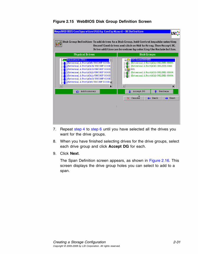
Creating a Storage Configuration 2-31Copyright © 2005-2008 by LSI Corporation. All rights reserved.
Figure 2.15 WebBIOS Disk Group Definition Screen
7. Repeat step 4 to step 6 until you have selected all the drives you want for the drive groups.
8. When you have finished selecting drives for the drive groups, select each drive group and click Accept DG for each.
9. Click Next.
The Span Definition screen appears, as shown in Figure 2.16. This screen displays the drive group holes you can select to add to a span.

2-32 WebBIOS Configuration UtilityCopyright © 2005-2008 by LSI Corporation. All rights reserved.
Figure 2.16 WebBIOS Span Definition Screen
10. Under the heading Array With Free Space, hold <Ctrl> while you select a drive group with two drives, and click Add to SPAN.
The drive group you select displays in the right frame under the heading Span.
11. Hold <Ctrl> while you select a second drive group with two drives, and click Add to SPAN.
Both drive groups display in the right frame under Span.
12. If there are additional drive groups with two drives each, you can add them to the virtual drive.
13. Click Next.
The Virtual Disk Definition screen appears, as shown in Figure 2.17. You use this screen to select the RAID level, stripe size, read policy, and other attributes for the new virtual drives.
14. Hold <Ctrl> while you select two drive groups with two drives in the Configuration panel on the right.

Creating a Storage Configuration 2-33Copyright © 2005-2008 by LSI Corporation. All rights reserved.
Figure 2.17 WebBIOS Virtual Disk Definition Screen
Note: The WebBIOS Configuration Utility displays the maximum available capacity while creating the RAID 10 drive group. In version 1.03 of the utility, the maximum size of the RAID 10 drive group is the sum total of the two RAID 1 drive groups. In version 1.1, the maximum size is the size of the smaller drive group multiplied by two.
15. Change the virtual drive options from the defaults listed on the screen as needed.
Here are brief explanations of the virtual drive options:
• RAID Level: The drop-down menu lists the possible RAID levels for the virtual drive. Select RAID 1.
• Stripe Size: The stripe size specifies the length of the data segments that the RAID controller writes across multiple drives, not including parity drives. For example, consider a stripe that contains 64 KB of drive space and has 16 KB of data residing on each drive in the stripe. In this case, the stripe size is 64 KB and the strip size is 16 KB. You can set the stripe size to 8, 16, 32, 64, 128, 256, 512, and 1024 Kbytes. A larger stripe size produces higher read

2-34 WebBIOS Configuration UtilityCopyright © 2005-2008 by LSI Corporation. All rights reserved.
performance. If your computer regularly performs random read requests, choose a smaller stripe size. The default is 64 Kbytes.
• Access Policy: Select the type of data access that is allowed for this virtual drive:
◊ RW: Allow read/write access.
◊ Read Only: Allow read-only access. This is the default.
◊ Blocked: Do not allow access.
• Read Policy: Specify the read policy for this virtual drive:
◊ Normal: This disables the read ahead capability. This is the default.
◊ Ahead: This enables read ahead capability, which allows the controller to read sequentially ahead of requested data and to store the additional data in cache memory, anticipating that the data will be needed soon. This speeds up reads for sequential data, but there is little improvement when accessing random data.
◊ Adaptive: When Adaptive read ahead is selected, the controller begins using read ahead if the two most recent drive accesses occurred in sequential sectors. If the read requests are random, the controller reverts to Normal (no read ahead).
• Write Policy: Specify the write policy for this virtual drive:
◊ WBack: In Writeback mode the controller sends a data transfer completion signal to the host when the controller cache has received all of the data in a transaction. This setting is recommended in Standard mode.
◊ WThru: In Writethrough mode the controller sends a data transfer completion signal to the host when the drive subsystem has received all of the data in a transaction. This is the default.
◊ Bad BBU: Select this mode if you want the controller to use Writeback mode but the controller has no BBU or the BBU is bad. If you do not choose this option, the controller firmware automatically switches to Writethrough mode if it detects a bad or missing BBU.

Creating a Storage Configuration 2-35Copyright © 2005-2008 by LSI Corporation. All rights reserved.
Caution: LSI allows Writeback mode to be used with or without a battery. LSI recommends that you use either a battery to protect the controller cache, or an uninterruptible power supply (UPS) to protect the entire system. If you do not use a battery or a UPS, and there is a power failure, you risk losing the data in the controller cache.
• IO Policy: The IO Policy applies to reads on a specific virtual drive. It does not affect the read ahead cache.
◊ Direct: In Direct I/O mode, reads are not buffered in cache memory. Data is transferred to the cache and the host concurrently. If the same data block is read again, it comes from cache memory. This is the default.
◊ Cached: In Cached I/O mode, all reads are buffered in cache memory.
• Disk Cache Policy: Specify the drive cache policy:
◊ Enable: Enable the drive cache.
◊ Disable: Disable the drive cache. This is the default.
◊ Unchanged: Leave the current drive cache policy unchanged.
• Disable BGI: Specify the background initialization status:
◊ No: Leave background initialization enabled. This means that a new configuration can be initialized in the background while you use WebBIOS to do other configuration tasks. This is the default.
◊ Yes: Select Yes if you do not want to allow background initializations for configurations on this controller.
• Select Size: Specify the size of the virtual drive in megabytes. Normally, this would be the full size for RAID 10 shown in the Configuration Panel on the right. You may specify a smaller size if you want to create other virtual drives on the same drive group.
16. Click Accept to accept the changes to the virtual drive definition, or click Reclaim to return to the previous settings.
17. When you are finished defining virtual drives, click Next .
The Configuration Preview screen appears, as shown in Figure 2.18.

2-36 WebBIOS Configuration UtilityCopyright © 2005-2008 by LSI Corporation. All rights reserved.
Figure 2.18 RAID 10 Configuration Preview
18. Check the information in the configuration preview.
19. If the virtual drive configuration is acceptable, click Accept to save the configuration. Otherwise, click Cancel to end the operation and return to the WebBIOS main menu, or click Back to return to the previous screens and change the configuration.
20. If you accept the configuration, click Yes at the prompt to save the configuration.
The WebBIOS main menu appears.
2.4.3.6 Using Custom Configuration: RAID 50
RAID 50 provides the features of both RAID 0 and RAID 5. RAID 50 uses both distributed parity and drive striping across multiple drive groups. It provides high data throughput, data redundancy, and very good performance. It is best implemented on two RAID 5 drive groups with data striped across both drive groups. Though multiple drive failures can be tolerated, only one drive failure can be tolerated in each RAID 5 level drive group.
Creating a Storage Configuration 2-37Copyright © 2005-2008 by LSI Corporation. All rights reserved.
RAID 50 is appropriate when used with data that requires high reliability, high request rates, high data transfer, and medium to large capacity.
When you select Custom Configuration and click Next, the Disk Group Definition screen appears. You use this screen to select drives to create drive group.
1. Hold <Ctrl> while selecting at least three ready drives in the Drives panel on the left.
2. Click AddtoArray to move the drives to a proposed drive group configuration in the Disk Groups panel on the right.
If you need to undo the changes, click the Reclaim button.
3. Click Accept DG to create a RAID 5 drive group.
An icon for a second drive group displays in the right panel.
4. Click on the icon for the second drive group to select it.
5. Hold <Ctrl> while selecting at least three more ready drives in the Drives panel to create a second drive group.
6. Click AddtoArray to move the drives to a proposed drive group configuration in the Disk Groups panel on the right, as shown in Figure 2.19.
If you need to undo the changes, click the Reclaim button.

2-38 WebBIOS Configuration UtilityCopyright © 2005-2008 by LSI Corporation. All rights reserved.
Figure 2.19 WebBIOS Disk Group Definition Screen
7. When you have finished selecting drives for the drive groups, select each drive group and click Accept DG for each.
8. Click Next.
The Span Definition screen appears, as shown in Figure 2.20. This screen displays the drive group holes you can select to add to a span.

Creating a Storage Configuration 2-39Copyright © 2005-2008 by LSI Corporation. All rights reserved.
Figure 2.20 WebBIOS Span Definition Screen
9. Under the heading Array With Free Space, hold <Ctrl> while you select a drive group of three or more drives, and click Add to SPAN.
The drive group you select displays in the right frame under the heading Span.
10. Hold <Ctrl> while you select a second drive group of three or more drives, and click Add to SPAN.
Both drive groups display in the right frame under Span.
11. Click Next.
The Virtual Disk Definition screen appears, as shown in Figure 2.21. You use this screen to select the RAID level, stripe size, read policy, and other attributes for the new virtual drive(s).
12. Hold <Ctrl> while you select two 3-drive drive groups in the Configuration panel on the right.

2-40 WebBIOS Configuration UtilityCopyright © 2005-2008 by LSI Corporation. All rights reserved.
Figure 2.21 WebBIOS Virtual Disk Definition Screen
13. Change the virtual drive options from the defaults listed on the screen as needed.
Here are brief explanations of the virtual drive options:
• RAID Level: The drop-down menu lists the possible RAID levels for the virtual drive. Select RAID 5.
• Stripe Size: The stripe size specifies the length of the data segments that the RAID controller writes across multiple drives, not including parity drives. For example, consider a stripe that contains 64 KB of drive space and has 16 KB of data residing on each drive in the stripe. In this case, the stripe size is 64 KB and the strip size is 16 KB. You can set the stripe size to 8, 16, 32, 64, 128, 256, 512, and 1024 Kbytes. A larger stripe size produces higher read performance. If your computer regularly performs random read requests, choose a smaller stripe size. The default is 64 Kbytes.
• Access Policy: Select the type of data access that is allowed for this virtual drive:
◊ RW: Allow read/write access.

Creating a Storage Configuration 2-41Copyright © 2005-2008 by LSI Corporation. All rights reserved.
◊ Read Only: Allow read-only access. This is the default.
◊ Blocked: Do not allow access.
• Read Policy: Specify the read policy for this virtual drive:
◊ Normal: This disables the read ahead capability. This is the default.
◊ Ahead: This enables read ahead capability, which allows the controller to read sequentially ahead of requested data and to store the additional data in cache memory, anticipating that the data will be needed soon. This speeds up reads for sequential data, but there is little improvement when accessing random data.
◊ Adaptive: When Adaptive read ahead is selected, the controller begins using read ahead if the two most recent drive accesses occurred in sequential sectors. If the read requests are random, the controller reverts to Normal (no read ahead).
• Write Policy: Specify the write policy for this virtual drive:
◊ WBack: In Writeback mode the controller sends a data transfer completion signal to the host when the controller cache has received all of the data in a transaction. This setting is recommended in Standard mode.
◊ WThru: In Writethrough mode the controller sends a data transfer completion signal to the host when the drive subsystem has received all of the data in a transaction. This is the default.
◊ Bad BBU: Select this mode if you want the controller to use Writeback mode but the controller has no BBU or the BBU is bad. If you do not choose this option, the controller firmware automatically switches to Writethrough mode if it detects a bad or missing BBU.
Caution: LSI allows Writeback mode to be used with or without a battery. LSI recommends that you use either a battery to protect the controller cache, or an uninterruptible power supply (UPS) to protect the entire system. If you do not use a battery or a UPS, and there is a power failure, you risk losing the data in the controller cache.

2-42 WebBIOS Configuration UtilityCopyright © 2005-2008 by LSI Corporation. All rights reserved.
• IO Policy: The IO Policy applies to reads on a specific virtual drive. It does not affect the read ahead cache.
◊ Direct: In Direct I/O mode, reads are not buffered in cache memory. Data is transferred to the cache and the host concurrently. If the same data block is read again, it comes from cache memory. This is the default.
◊ Cached: In Cached I/O mode, all reads are buffered in cache memory.
• Disk Cache Policy: Specify the drive cache policy:
◊ Enable: Enable the drive cache.
◊ Disable: Disable the drive cache. This is the default.
◊ Unchanged: Leave the current drive cache policy unchanged.
• Disable BGI: Specify the background initialization status:
◊ No: Leave background initialization enabled. This means that a new configuration can be initialized in the background while you use WebBIOS to do other configuration tasks. This is the default.
◊ Yes: Select Yes if you do not want to allow background initializations for configurations on this controller.
• Select Size: Specify the size of the virtual drive in megabytes. Normally, this would be the full size for RAID 50 shown in the Configuration Panel on the right. You may specify a smaller size if you want to create other virtual drives on the same drive group.
14. Click Accept to accept the changes to the virtual drive definition, or click Reclaim to return to the previous settings.
15. Click Next when you are finished defining virtual drives.
The Configuration Preview screen appears, as shown in Figure 2.22.

Creating a Storage Configuration 2-43Copyright © 2005-2008 by LSI Corporation. All rights reserved.
Figure 2.22 RAID 50 Configuration Preview
16. Check the information in the configuration preview.
17. If the virtual drive configuration is acceptable, click Accept to save the configuration. Otherwise, click Cancel to end the operation and return to the WebBIOS main menu, or click Back to return to the previous screens and change the configuration.
18. If you accept the configuration, click Yes at the prompt to save the configuration.
The WebBIOS main menu appears.
2.4.3.7 Using Custom Configuration: RAID 60
RAID 60 provides the features of both RAID 0 and RAID 6, and includes both parity and drive striping across multiple drive groups. RAID 6 supports two independent parity blocks per stripe. A RAID 60 virtual drive can survive the loss of two drives in each of the RAID 6 sets without losing data. RAID 60 is best implemented on two RAID 6 drive groups with data striped across both drive groups. Use RAID 60 for data that requires a very high level of protection from loss.

2-44 WebBIOS Configuration UtilityCopyright © 2005-2008 by LSI Corporation. All rights reserved.
RAID 60 can support up to eight spans and tolerate up to 16 drive failures, though less than total drive capacity is available. Two drive failures can be tolerated in each RAID 6 level drive group.
RAID 60 is appropriate when used with data that requires high reliability, high request rates, high data transfer, and medium to large capacity.
When you select Custom Configuration and click Next, the Disk Group Definition screen appears. You use this screen to select drives to create drive groups.
1. Hold <Ctrl> while selecting at least three ready drives in the Drives panel on the left.
2. Click AddtoArray to move the drives to a proposed drive group configuration in the Disk Groups panel on the right.
If you need to undo the changes, click the Reclaim button.
3. Click Accept DG to create a RAID 6 drive group.
An icon for a second drive group displays in the right panel.
4. Click on the icon for the second drive group to select it.
5. Hold <Ctrl> while selecting at least three more ready drives in the Drives panel to create a second drive group.
6. Click AddtoArray to move the drives to a proposed drive group configuration in the Disk Groups panel on the right, as shown in Figure 2.19.
If you need to undo the changes, click the Reclaim button.

Creating a Storage Configuration 2-45Copyright © 2005-2008 by LSI Corporation. All rights reserved.
Figure 2.23 WebBIOS Disk Group Definition Screen
7. When you have finished selecting drives for the drive groups, select each drive group and click Accept DG for each.
8. Click Next.
The Span Definition screen appears, as shown in Figure 2.24. This screen displays the drive group holes you can select to add to a span.

2-46 WebBIOS Configuration UtilityCopyright © 2005-2008 by LSI Corporation. All rights reserved.
Figure 2.24 WebBIOS Span Definition Screen
9. Under the heading Array With Free Space, hold <Ctrl> while you select a drive group of three or more drives, and click Add to SPAN.
The drive group you select displays in the right frame under the heading Span.
10. Hold <Ctrl> while you select a second drive group of three or more drives, and click Add to SPAN.
Both drive groups display in the right frame under Span.
11. Click Next.
The Virtual Disk Definition screen appears, as shown in Figure 2.21. You use this screen to select the RAID level, stripe size, read policy, and other attributes for the new virtual drive(s).
12. Hold <Ctrl> while you select two 3-drive drive groups in the Configuration window on the right.

Creating a Storage Configuration 2-47Copyright © 2005-2008 by LSI Corporation. All rights reserved.
Figure 2.25 WebBIOS Virtual Disk Definition Screen
13. Change the virtual drive options from the defaults listed on the screen as needed.
Here are brief explanations of the virtual drive options:
• RAID Level: The drop-down menu lists the possible RAID levels for the virtual drive. Select RAID 6.
• Stripe Size: The stripe size specifies the length of the data segments that the RAID controller writes across multiple drives, not including parity drives. For example, consider a stripe that contains 64 KB of drive space and has 16 KB of data residing on each drive in the stripe. In this case, the stripe size is 64 KB and the strip size is 16 KB. You can set the stripe size to 8, 16, 32, 64, 128, 256, 512, and 1024 Kbytes. A larger stripe size produces higher read performance. If your computer regularly performs random read requests, choose a smaller stripe size. The default is 64 Kbytes.
• Access Policy: Select the type of data access that is allowed for this virtual drive:
◊ RW: Allow read/write access.

2-48 WebBIOS Configuration UtilityCopyright © 2005-2008 by LSI Corporation. All rights reserved.
◊ Read Only: Allow read-only access. This is the default.
◊ Blocked: Do not allow access.
• Read Policy: Specify the read policy for this virtual drive:
◊ Normal: This disables the read ahead capability. This is the default.
◊ Ahead: This enables read ahead capability, which allows the controller to read sequentially ahead of requested data and to store the additional data in cache memory, anticipating that the data will be needed soon. This speeds up reads for sequential data, but there is little improvement when accessing random data.
◊ Adaptive: When Adaptive read ahead is selected, the controller begins using read ahead if the two most recent drive accesses occurred in sequential sectors. If the read requests are random, the controller reverts to Normal (no read ahead).
• Write Policy: Specify the write policy for this virtual drive:
◊ WBack: In Writeback mode the controller sends a data transfer completion signal to the host when the controller cache has received all of the data in a transaction. This setting is recommended in Standard mode.
◊ WThru: In Writethrough mode the controller sends a data transfer completion signal to the host when the drive subsystem has received all of the data in a transaction. This is the default.
◊ Bad BBU: Select this mode if you want the controller to use Writeback mode but the controller has no BBU or the BBU is bad. If you do not choose this option, the controller firmware automatically switches to Writethrough mode if it detects a bad or missing BBU.
Caution: LSI allows Writeback mode to be used with or without a battery. LSI recommends that you use either a battery to protect the controller cache, or an uninterruptible power supply (UPS) to protect the entire system. If you do not use a battery or a UPS, and there is a power failure, you risk losing the data in the controller cache.

Creating a Storage Configuration 2-49Copyright © 2005-2008 by LSI Corporation. All rights reserved.
• IO Policy: The IO Policy applies to reads on a specific virtual drive. It does not affect the read ahead cache.
◊ Direct: In Direct I/O mode, reads are not buffered in cache memory. Data is transferred to the cache and the host concurrently. If the same data block is read again, it comes from cache memory. This is the default.
◊ Cached: In Cached I/O mode, all reads are buffered in cache memory.
• Disk Cache Policy: Specify the drive cache policy:
◊ Enable: Enable the drive cache.
◊ Disable: Disable the drive cache. This is the default.
◊ Unchanged: Leave the current drive cache policy unchanged.
• Disable BGI: Specify the background initialization status:
◊ No: Leave background initialization enabled. This means that a new configuration can be initialized in the background while you use WebBIOS to do other configuration tasks. This is the default.
◊ Yes: Select Yes if you do not want to allow background initializations for configurations on this controller.
• Select Size: Specify the size of the virtual drive in megabytes. Normally, this would be the full size for RAID 60 shown in the Configuration panel on the right. You may specify a smaller size if you want to create other virtual drives on the same drive group.
Note: WebBIOS does not not allow you to select 8 Kbytes as the stripe size when you create a RAID 60 drive group with six drives.
14. Click Accept to accept the changes to the virtual drive definition, or click Reclaim to return to the previous settings.
15. Click Next when you are finished defining virtual drives.
The Configuration Preview screen appears, as shown in Figure 2.22.

2-50 WebBIOS Configuration UtilityCopyright © 2005-2008 by LSI Corporation. All rights reserved.
Figure 2.26 RAID 60 Configuration Preview
16. Check the information in the configuration preview.
17. If the virtual drive configuration is acceptable, click Accept to save the configuration. Otherwise, click Cancel to end the operation and return to the WebBIOS main menu, or click Back to return to the previous screens and change the configuration.
18. If you accept the configuration, click Yes at the prompt to save the configuration.
The WebBIOS main menu appears.
2.5 Viewing and Changing Device Properties
This section explains how you can use the WebBIOS CU to view and change the properties for controllers, virtual drives, drives, and BBUs.

Viewing and Changing Device Properties 2-51Copyright © 2005-2008 by LSI Corporation. All rights reserved.
2.5.1 Viewing and Changing Controller Properties
WebBIOS allows you to view information for one LSI SAS controller at a time. If your computer system has multiple LSI SAS controllers, you can view information for a different controller by clicking Adapter Selection on the main screen. When the Adapter Selection screen appears, select the controller you want from the list.
To view the properties for the currently selected controller, click Adapter Properties on the main WebBIOS screen. There are two Adapter Properties screens. Figure 2.27 shows the first screen.
Figure 2.27 First Adapter Properties Screen
The information on this screen is read-only and cannot be modified directly. Most of this information is self-explanatory. The screen lists the number of virtual drives that are already defined on this controller, plus the number of drives connected to the controller.
If a background initialization is in progress, you can click Background Init Progress to determine its state of completion. Click Next to view the second Adapter Properties screen, as shown in Figure 2.28.

2-52 WebBIOS Configuration UtilityCopyright © 2005-2008 by LSI Corporation. All rights reserved.
Figure 2.28 Second Adapter Properties Screen
Table 2.2 describes the entries/options listed on the second Adapter Properties screen. LSI recommends that you leave these options at their default settings to achieve the best performance, unless you have a specific reason for changing them.
Table 2.2 Adapter Properties Menu Options
Option Description
Battery Backup This entry indicates whether the selected controller has a BBU. If present, you can click Present to view information about the BBU. For more information, see Section 2.5.4, “Viewing Battery Backup Unit Information.”
Set Factory Defaults Use this option to load the default MegaRAID® WebBIOS CU settings. The default is No.
Cluster Mode Use this option to enable or disable Cluster mode. The default is Disabled. A cluster is a grouping of independent servers that can access the same data storage and provide services to a common set of clients. When Cluster mode is disabled, the system operates in Standard mode.
Rebuild Rate Use this option to select the rebuild rate for drives connected to the selected controller. The default is 30 percent. The rebuild rate is the percentage of system resources dedicated to rebuilding a failed drive. The higher the number, the more system resources devoted to a rebuild.
BGI Rate Use this option to select the amount of system resources dedicated to background initialization of virtual drives connected to the selected controller. The default is 30 percent.

Viewing and Changing Device Properties 2-53Copyright © 2005-2008 by LSI Corporation. All rights reserved.
If you make changes to the options on this screen, click Submit to register them. If you change your mind, click Reset to return the options to their default values.
CC Rate Use this option to select the amount of system resources dedicated to consistency checks of virtual drives connected to the selected controller. The default is 30 percent.
Reconstruction Rate Use this option to select the amount of system resources dedicated to reconstruction of drives connected to the selected controller. The default is 30 percent.
Adapter BIOS Use this option to enable or disable the BIOS for the selected controller. The default is Enabled. If the boot device is on the selected controller, the BIOS must be enabled; otherwise, the BIOS should be disabled or it might not be possible to use a boot device elsewhere.
Connector 1 Identifies where the chain of enclosures is connected to the RAID controller.
Coercion Mode Drive coercion is a tool for forcing drives of varying capacities to the same size so they can be used in a drive group. The coercion mode options are None, 128MB-way, and 1GB-way. The default is None.Note: The number you choose depends on how much the drives from var-
ious vendors vary in their actual size. LSI recommends that you use the 1GB coercion mode option.
PDF Interval This option determines how frequently the controller polls for drives reporting a Predictive Drive Failure (S.M.A.R.T. error). The default is 300 seconds (5 minutes).
Alarm Control Select this option to enable, disable, or silence the onboard alarm tone generator on the controller. The default is Disabled.
Patrol Read Rate Use this option to select the rate for patrol reads for drives connected to the selected controller. The default is 30 percent. The patrol read rate is the percentage of system resources dedicated to running a patrol read. See Section 3.6, “Patrol Read-Related Adapter Properties” for additional information about patrol read.
Cache Flush Interval Use this option to control the interval (in seconds) at which the contents of the onboard data cache are flushed. The default is 4 seconds.
Spinup Drive Count Use this option to control the number of drives that spin up simultaneously. The default is 2 drives.
Spinup Delay Use this option to control the interval (in seconds) between spinup of drives connected to this controller. The delay prevents a drain on the system’s power supply that would occur if all drives spun up at the same time. The default is 12 seconds.
StopOnError Enable this option if you want the boot process to stop when the controller BIOS encounters an error during boot-up. The default is Disabled.
Connector 2 Identifies where the chain of enclosures is connected to the RAID controller.
Table 2.2 Adapter Properties Menu Options (Cont.)
Option Description

2-54 WebBIOS Configuration UtilityCopyright © 2005-2008 by LSI Corporation. All rights reserved.
2.5.2 Viewing and Changing Virtual Drive Properties
Access the Virtual Disk screen by clicking on a virtual drive in the list of virtual drives in the right panel on the WebBIOS CU main screen. The Virtual Disk screen displays, as shown in Figure 2.29.
Figure 2.29 Virtual Disk Screen
The Properties panel of this screen displays the virtual drive’s RAID level, state, size, and stripe size.
The Policies panel lists the virtual drive policies that were defined when the storage configuration was created. For information about these policies, see Section 2.4.3, “Using Custom Configuration.” To change any of these policies, make a selection from the drop-down menu and click Change.
The Operations panel lists operations that can be performed on the virtual drive. To perform an operation, select it and click Go. Then choose from the following options:

Viewing and Changing Device Properties 2-55Copyright © 2005-2008 by LSI Corporation. All rights reserved.
• Select Del to delete this virtual drive. For more information, see Section 2.7.2, “Deleting a Virtual Drive.”
• Select Locate to make the LEDs flash on the drives used by this virtual drive. This works only if the drives are installed in a drive enclosure that supports SAFTE.
• Select Fast or Slow to initialize this virtual drive. A fast initialization quickly writes zeroes to the first and last 10 Mbyte regions of the new virtual drive and then completes the initialization in the background. A slow initialization is not complete until the entire virtual drive has been initialized with zeroes. It is seldom necessary to use this option, because the virtual drive was already initialized when you created it.
Caution: Before you run an initialization, back up any data on the virtual drive that you want to save. All data on the virtual drive is lost when you initialize it.
• Select CC to run a consistency check on this virtual drive. For more information, see Section 2.7.1, “Running a Consistency Check.” (This option is not available for RAID 0 virtual drives.)
In the right panel of the Virtual Disk screen you can change the virtual drive configuration by adding or removing a drive or by changing the RAID level.
Caution: Before you change a virtual drive configuration, back up any data on the virtual drive that you want to save.
To remove a drive from a virtual drive, select the drive in the small panel beneath the Remove physical drive option. Then select Remove physical drive and click Go at the bottom of the panel.
See Section 2.7.4, “Migrating the RAID Level of a Virtual Drive” for information about adding a drive to a virtual drive or migrating its RAID level.
2.5.3 Viewing Drive Properties
The Physical Drive screen displays the properties of a selected drive and enables you to perform operations on the drive. There are two ways to access the Physical Drive screen:

2-56 WebBIOS Configuration UtilityCopyright © 2005-2008 by LSI Corporation. All rights reserved.
• On the main menu screen, click on a drive in the right panel under the heading Physical Drives.
• On the main menu screen, click on Physical Drives in the left panel to display the Physical Drive screen. Then click on a drive in the right panel. Click on the Properties button, and click Go. The properties for the selected drive displays.
Figure 2.30 shows the Physical Drive screen.
Figure 2.30 Physical Drive Screen
The drive properties are view-only and are self-explanatory. Note that the properties include the state of the drive.
Operations you can perform are listed at the bottom of the screen, After you select an operation, click Go to start the operation. The operations vary depending on the drive state. If the drive state is Online, the following operations appear:
• Select MakeDriveOffline if you want to force the drive offline.
Note: If you force offline a good drive that is part of a redundant drive group with a hot spare, the drive will rebuild to the hot spare drive. The drive you forced offline will go into the Unconfigured Bad state. Access the BIOS utility to set the drive to the Unconfigured Good state.

Viewing and Changing Device Properties 2-57Copyright © 2005-2008 by LSI Corporation. All rights reserved.
• Select Locate to make the LED flash on the drive. This works only if the drive is installed in a drive enclosure.
If the drive state is Unconfigured Good, four additional operations appear on this screen:
• Select Make Global HSP to make a global hot spare, available to all of the virtual drives.
• Select Make Dedicated HSP to make a hot spare dedicated to a specific virtual drive.
WebBIOS displays the global hot spare as Global and the dedicated hot spare as Ded. The icon for the dedicated hot spare displays under its associated virtual drive. The drive number, drive state, drive capacity, and drive manufacturer display.
• Select Enclosure Affinity so if there are drive failures present on a split backplane configuration, then the hotspare will be used first on the backplane side that it resides in.
• Select Prepare for Removal to prepare the drive for removal from the enclosure.
2.5.4 Viewing Battery Backup Unit Information
If your SAS controller has a battery backup unit (BBU), you can view information about it. To do this, follow these steps:
1. Click Adapter Properties on the main WebBIOS CU screen.
2. Click Next to view the second Adapter Properties screen.
3. Click the word Present in the Battery Backup field at the top left of the screen.
The Battery Module screen appears, as shown in Figure 2.31.

2-58 WebBIOS Configuration UtilityCopyright © 2005-2008 by LSI Corporation. All rights reserved.
Figure 2.31 Battery Module Screen
Most of the Battery Module properties are view-only and are self-explanatory. In the lower right panel, there are two properties that can be changed. (LSI recommends that you leave these properties at their default settings.)
A learning cycle is a battery calibration operation performed by the controller periodically to determine the condition of the battery. To change the length of the interval between learning cycles, enter a different number of hours for Learn Delay Interval and click Go.
Note: LSI recommends 30 days for the interval between cycles.
2.6 Viewing System Event Information
The SAS controller firmware monitors the activity and performance of all storage configurations and devices in the system. When an event occurs (such as the creation of a new virtual drive or the removal of a drive) an event message is generated and is stored in the controller NVRAM. You can use the WebBIOS CU to view these event messages. To do this,

Viewing System Event Information 2-59Copyright © 2005-2008 by LSI Corporation. All rights reserved.
click Events on the main WebBIOS CU screen. The Event Information screen appears, as shown in Figure 2.32.
Figure 2.32 Event Information Screen
The right side of the screen is blank until you select an event to view. The First Sequence and Last Sequence fields in the upper left of the screen show you how many event entries are currently stored.
To view event information, follow these steps:
1. Select an Event Locale from the menu. For example, select Enclosure to view events relating to the drive enclosure.
2. Select an Event Class: Information, Warning, Critical, Fatal, or Dead.
3. Enter a Start Sequence number, between the First Sequence and Last Sequence numbers. The higher the number, the more recent the event.
4. Enter the Number of events of this type that you want to view, and click Go.
The first event in the sequence appears in the right panel.
5. Click Next or Prev to page forward or backward through the sequence of events.

2-60 WebBIOS Configuration UtilityCopyright © 2005-2008 by LSI Corporation. All rights reserved.
6. If you want, select different event criteria in the left panel, and click Go again to view a different sequence of events.
Each event entry includes a timestamp and a description to help you determine when the event occurred and what it was.
2.7 Managing Configurations
This section includes information about maintaining and managing storage configurations.
2.7.1 Running a Consistency Check
You should periodically run a consistency check on fault-tolerant virtual drives. A consistency check verifies that the redundancy data is correct and available for RAID 1, RAID 5, RAID 6, RAID 10, RAID 50, and RAID 60 drive groups. To do this, follow these steps:
1. On the main WebBIOS CU screen, select a virtual drive.
2. Click Virtual Disks.
3. When the Virtual Disk screen appears, select CC in the lower left panel, and click Go.
The consistency check begins.
If the WebBIOS CU finds a difference between the data and the parity value on the redundant drive group, it assumes that the data is accurate and automatically corrects the parity value. Be sure to back up the data before running a consistency check if you think the consistency data may be corrupted.
2.7.2 Deleting a Virtual Drive
You can delete any virtual drive on the controller if you want to reuse that space for a new virtual drive. The WebBIOS CU provides a list of configurable drive groups where there is a space to configure. If multiple virtual drives are defined on a single drive group, you can delete a virtual drive without deleting the whole drive group.
To delete a virtual drive, follow these steps:

Managing Configurations 2-61Copyright © 2005-2008 by LSI Corporation. All rights reserved.
Caution: Back up any data that you want to keep before you delete the virtual drive.
1. On the main WebBIOS CU screen, select a virtual drive.
2. Click Virtual Disks.
3. When the Virtual Disk screen appears, select Del in the lower left panel, and click Go.
4. When the message appears, confirm that you want to delete the virtual drive.
2.7.3 Importing or Clearing a Foreign Configuration
A foreign configuration is a storage configuration that already exists on a replacement set of drives that you install in a computer system. In addition, if one or more drives are removed from a configuration, by a cable pull or drive removal, for example, the configuration on those drives is considered a foreign configuration by the RAID controller.
The BIOS CU allows you to import the foreign configuration to the RAID controller, or to clear the configuration so you can create a new configuration using these drives.
Note: When you create a new configuration, the WebBIOS CU shows only the unconfigured drives. Drives that have existing configurations, including foreign configurations, will not appear. To use drives with existing configurations, you must first clear the configuration on those drives.
If WebBIOS CU detects a foreign configuration, the import screen appears, as shown in Figure 2.33.

2-62 WebBIOS Configuration UtilityCopyright © 2005-2008 by LSI Corporation. All rights reserved.
Figure 2.33 Foreign Configuration Screen
The GUID (Global Unique Identifier) entries on the drop-down list are OEM names and will vary from one installation to another.
Click GUIDPreview if you want to preview the foreign configuration. The preview screen appears, as shown in Figure 2.34.
Click ClearForeignCfg if you want to clear the configuration and reuse the drives for another virtual drive.
Click Cancel to cancel the importation or preview of the configuration.
Figure 2.34 Foreign Configuration Preview Screen

Managing Configurations 2-63Copyright © 2005-2008 by LSI Corporation. All rights reserved.
The right panel shows the virtual drive properties of the foreign configuration. In this example, there is a RAID 1 virtual drive with 1,000 Mbytes. The left panel shows the drives that comprise the foreign configuration.
Click Import to import this foreign configuration and use it on this controller.
Click Cancel to clear the configuration and reuse the drives for another virtual drive.
2.7.3.1 Foreign Configurations in Cable Pull and Drive Removal Scenarios
If one or more drives are removed from a configuration, by a cable pull or drive removal, for example, the configuration on those drives is considered a foreign configuration by the RAID controller.
Use the Foreign Configuration Preview screen to import or clear the foreign configuration in each case. The import procedure and clear procedure are described in Section 2.7.3, “Importing or Clearing a Foreign Configuration.”
The following scenarios can occur with cable pulls or drive removals.
Note: If you want to import the foreign configuration in any of the following scenarios, you should have all of the drives in the enclosure before you perform the import operation.
1. Scenario #1: If all of the drives in a configuration are removed and re-inserted, the controller considers the drives to have foreign configurations.
Import or clear the foreign configuration. If you select Import, automatic rebuilds will occur in redundant virtual drives.
Note: Start a consistency check immediately after the rebuild is complete to ensure data integrity for the virtual drives. See Section 2.7.1, “Running a Consistency Check,” for more information about checking data consistency.
2. Scenario #2: If some of the drives in a configuration are removed and re-inserted, the controller considers the drives to have foreign configurations.

2-64 WebBIOS Configuration UtilityCopyright © 2005-2008 by LSI Corporation. All rights reserved.
Import or clear the foreign configuration. If you select Import, automatic rebuilds will occur in redundant virtual drives.
Note: Start a consistency check immediately after the rebuild is complete to ensure data integrity for the virtual drives. See Section 2.7.1, “Running a Consistency Check,” for more information about checking data consistency.
3. Scenario #3: If all of the drives in a virtual drive are removed, but at different times, and re-inserted, the controller considers the drives to have foreign configurations.
Import or clear the foreign configuration. If you select Import, all drives that were pulled before the virtual drive became offline will be imported and then automatically rebuilt. Automatic rebuilds will occur in redundant virtual drives.
4. If the drives in a non-redundant virtual drive are removed, the controller considers the drives to have foreign configurations.
Import or clear the foreign configuration. No rebuilds will occur after the import operation because there is no redundant data to rebuild the drives with.
2.7.3.2 Importing Foreign Configurations from Integrated RAID to MegaRAID
The LSI Integrated RAID solution simplifies the configuration options and provides firmware support in its host controllers. LSI offers two types of Integrated RAID (IR): Integrated Mirroring (IM) and Integrated Striping (IS).
You can import an IM or IS RAID configuration from an IR system into a MegaRAID system. The MegaRAID system treats the IR configuration as a foreign configuration. You can import or clear the IR configuration.
Note: For more information about Integrated RAID, refer to the Integrated RAID for SAS User’s Guide. You can find this document on the LSI web site at: http://www.lsi.com/cm/DownloadSearch.do.
2.7.3.3 Troubleshooting Information
An IR virtual drive can have either 64 Mbytes or 512 Mbytes available for metadata at the end of the drive. This data is in LSI Data Format

Managing Configurations 2-65Copyright © 2005-2008 by LSI Corporation. All rights reserved.
(LDF). MegaRAID virtual drives have 512 Mbytes for metadata at the end of the drive in the Disk Data format (DDF).
To import an IR virtual drive into MegaRAID, the IR virtual drive must have 512 Mbytes in the metadata, which is the same amount of megadata as in a MegaRAID virtual drive. If the IR virtual drive has only 64 Mbytes when you attempt to import it into MegaRAID, the import will fail because the last 448 Mbytes of your data will be overwritten and the data lost.
If your IR virtual drive has only 64 Mbytes for metadata at the end of the drive, you cannot import the virtual drive into MegaRAID. You need to use another upgrade method, such as backup/restore to the upgraded virtual drive type.
In order to import an IR virtual drive into a MegaRAID system, use the Foreign Configuration Preview screen to import or clear the foreign configuration. The import procedure and the clear procedure are described in Section 2.7.3, “Importing or Clearing a Foreign Configuration.”
2.7.4 Migrating the RAID Level of a Virtual Drive
As the amount of data and the number of drives in your system increase, you can use RAID-level migration to change a virtual drive from one RAID level to another. You do not have to power down or reboot the system. When you migrate a virtual drive, you can keep the same number of drives, or you can add drives. You can use the WebBIOS CU to migrate the RAID level of an existing virtual drive.
Note: While you can apply RAID-level migration at any time, LSI recommends that you do so when there are no reboots. Many operating systems issues I/O operations serially (one at a time) during boot. With a RAID-level migration running, a boot can often take more than 15 minutes.
Migrations are allowed for the following RAID levels:
• RAID 0 to RAID 1
• RAID 0 to RAID 5
• RAID 1 to RAID 5

2-66 WebBIOS Configuration UtilityCopyright © 2005-2008 by LSI Corporation. All rights reserved.
• RAID 1 to RAID 6
• RAID 5 to RAID 6
Table 2.3 lists the number of additional drives required when you change the RAID level of a virtual drive.
Follow these steps to migrate the RAID level:
Caution: Back up any data that you want to keep before you change the RAID level of the virtual drive.
1. On the main WebBIOS CU screen, select a virtual drive.
2. Click Virtual Disks.
3. When the Virtual Disk screen appears, select Migration only (and skip to step 6) or Migration with addition in the right panel.
4. If you selected Migration with addition, select one or more drives from the small window in the lower right of the screen.
5. Select a new RAID level from the drop-down menu on the right. The available RAID levels are limited, based on the current RAID level of the virtual drive plus the number of drives available.
6. When you have made your selections, click Go at the bottom of the right panel.
7. When the message appears, confirm that you want to migrate the RAID level of the virtual drive.
A reconstruction operation begins on the virtual drive. You must wait until the reconstruction is completed before you perform any other tasks in the WebBIOS CU.
Table 2.3 Additional Drives Required for RAID-Level Migration
From RAID Level to RAID Level
Original Number of Drives in Drive Group Additional Drives Required
RAID 0 to RAID 1 RAID 0: 1 drive 1
RAID 0 to RAID 5 RAID 0: 1 drive 2
RAID 1 to RAID 5 RAID 1: 2 drives 1
RAID 1 to RAID 6 RAID 1: 2 drives 1

MegaRAID SAS Software User’s Guide 3-1Copyright © 2005-2008 by LSI Corporation. All rights reserved.
Chapter 3MegaRAID Command Tool
The MegaRAID Command Tool (CT) is a command line interface (CLI) application for SAS. You can use this utility to configure, monitor, and maintain MegaRAID SAS RAID controllers and the devices connected to them.
Note: The CT supports only the MegaRAID controller. It supports SAS and SATA II, but does not support other types of MegaRAID controllers, such as U320, SATA I, or IDE.
This chapter has the following sections:
• Section 3.1, “Product Overview”
• Section 3.2, “Novell, SCO, and Solaris Operating System Support”
• Section 3.3, “MegaCLI Version 1.00.22 Upgrade for Linux.”
• Section 3.4, “Command Line Abbreviations and Conventions”
• Section 3.5, “Adapter Property-Related Options”
• Section 3.6, “Patrol Read-Related Adapter Properties”
• Section 3.7, “BIOS-Related Properties”
• Section 3.8, “Battery Backup Unit-Related Properties”
• Section 3.9, “Options for Displaying Logs Kept at Firmware Level”
• Section 3.10, “Configuration-Related Options”
• Section 3.11, “Virtual Drive-Related Options”
• Section 3.12, “Drive-Related Options”
• Section 3.13, “Enclosure-Related Options”
• Section 3.14, “Flashing the Firmware”
• Section 3.15, “SAS Topology”

3-2 MegaRAID Command ToolCopyright © 2005-2008 by LSI Corporation. All rights reserved.
• Section 3.16, “Diagnostic-Related Options”
• Section 3.17, “Miscellaneous Options”
3.1 Product Overview
The MegaCLI Configuration Utility is a command line interface application you can use to manage MegaRAID SAS RAID controllers. You can use MegaCLI Configuration Utility to perform the following tasks:
• Configure MegaRAID SAS RAID controllers and attached devices
• Display information about virtual drives and drives for the controller and other storage components
• Display ongoing progress for operations on drives and virtual drives
• Change properties for the virtual drives and drives for the controller and other storage components
• Set, retrieve, and verify controller default settings
• Change the firmware on the controllers
• Monitor the RAID storage systems
• Support RAID levels 0, 1, 5, 6, 10, 50, and 60 (depending on the RAID controller)
• Create and use scripts with the scriptable CLI tool
• Configure drive into groups and virtual drives on the controller
• Display configuration information for the controller, drives, and virtual drives
• Change virtual drive properties on the controller
• Change drive properties on the controller
• Display controller properties
• Load configuration to the controller from a file
• Save the controller configuration to a file
• Start or stop a rebuild, consistency check (CC), or initialization operation
• Enable or disable a background initialization (BGI)
Novell, SCO, and Solaris Operating System Support 3-3Copyright © 2005-2008 by LSI Corporation. All rights reserved.
• Stop or display an ongoing background initialization
• Start or display a reconstruction
• Start or stop patrol read
• Set and retrieve patol read related settings
• Flash new firmware on the SAS RAID controller
• Read and program NVRAM and flash memory directly into DOS
• Display relevant messages on the console and/or in the log file
• Display controller data using one command
• Exit with predefined success or failure exit codes
• Scan, preview, and import foreign configurations
• Set predefined environment variables, such as the number of controllers and virtual drives
• Display firmware event logs
• Display help for how to use the command line options:
• Display battery unit properties
• Display enclosure properties
• Display and set connector mode on supported controllers
The following sections describe the command line options in the MegaCLI Configuration Utility you can use to perform these functions.
3.2 Novell, SCO, and Solaris Operating System Support
The MegaCLI Configuration Utility functions under the Novell® NetWare®, SCO® OpenServer™, SCO UnixWare®, and Solaris operating systems in the same way that it does under the Windows and Linux operating systems. All of the commands supported for the Windows and Linux operating systems are supported for the NetWare, SCO, and Solaris operating systems as well.
For the SCO OpenServer and SCO UnixWare operating systems, LSI provides an executable file that you can execute from any folder, and an image of the same executable file on a floppy drive. The image filename

3-4 MegaRAID Command ToolCopyright © 2005-2008 by LSI Corporation. All rights reserved.
is MegaCLI.image. The floppy disk is provided so that you can distribute MegaCLI and install the executable file later as needed.
For the Solaris operating system, LSI provides an executable file that you can execute from any folder. No installation is required.
For the Novell NetWare operating system, LSI provides an executable file, MegaCLI.nlm, that you can execute from any folder. No installation is required. The output of all of the commands appears in the console window.
3.3 MegaCLI Version 1.00.22 Upgrade for Linux
Note: This section is for the Linux operating system only. You can upgrade the MegaCLI version in other operating systems, but only Linux requires this procedure.
If you want to upgrade from MegaCLI version 1.00.09 to MegaCLI version 1.00.22, you need to remove version 1.00.09 first. Version 1.00.22 can not uninstall the older version. This is because of the way that the RPM Package Manager installs MegaCLI and the location in which the older versions were installed. MegaCLI version 1.00.09 was installed to /usr/sbin, and MegaCLI version 1.00.22 is installed to /opt/megaraid.
To remove version 1.00.09, perform the following steps:
1. Go to the location of the MegaCLI and type rpm –q.
The package name displays.
2. Use the rpm -e command to remove the older version and then install the new version.
For example, for version MegaCLI-1.01.26-0, type rpm –e MegaCli-1.01.26-0 to remove the package.
3.4 Command Line Abbreviations and Conventions
This section explains the abbreviations and conventions used with MegaCLI Configuration Utility commands.

Command Line Abbreviations and Conventions 3-5Copyright © 2005-2008 by LSI Corporation. All rights reserved.
3.4.1 Abbreviations Used in the Command Line
Table 3.1 lists the abbreviations for the virtual drive parameters used in the following sections.
3.4.2 Conventions
There are some options for which you can specify multiple values. You can enter commands for a single controller (–aN), multiple controllers (-a0,1,2) or work on all present controllers (-aALL). This is denoted as –aN|-a0,1,2|-aALL in this document and specifies that you can enter commands for one controller, multiple controllers, or all controllers.
Note : All options in the MegaRAID Command Tool are position-dependent, unless otherwise specified.
Table 3.2 describes the conventions used in the options.
Table 3.1 Command Line Abbreviations
Abbreviation Description
WB WriteBack write policy
WT WriteThrough write policy
ADRA Adaptive Read Ahead read policy
RA Read Ahead read policy
NORA Normal Read policy (No read ahead)
DIO Direct I/O cache policy
CIO Cached I/O cache policy
Table 3.2 Conventions
Convention Description
| Specifies “or,” meaning you can choose between options.
-aN N specifies the controller number for the command.
-a0,1,2 Specifies the command is for controllers 0, 1, and 2. You can select two or more controllers in this manner.
-aALL Specifies the command is for all controllers.
-Lx x specifies the virtual drive number for the command.
-L0,1,2 Specifies the command is for virtual drives 0, 1, and 2. You can select two or more virtual drives in this manner.

3-6 MegaRAID Command ToolCopyright © 2005-2008 by LSI Corporation. All rights reserved.
You can specify the -Silent command line option for all possible functions of the MegaCLI Configuration Utility. If you enter this option at the command line, no message displays on the screen.
3.5 Adapter Property-Related Options
You can use the commands in this section to set or display properties related to the controller(s), such as the virtual drive parameters and factory defaults.
3.5.1 Display Adapter Properties
Use the command in Table 3.3 to display parameters for the selected controller(s).
-Lall Specifies the command is for all virtual drives.
[E0:S0,E1,S1,…] Specifies when one or more physical devices need(s) to be specified in the command line. Each [E:S] pair specifies one physical device where E means device ID of the enclosure in which a drive resides, and S means the slot number of the enclosure.
In the case of a physical device directly connected to the SAS port on the controller, with no enclosure involved, the format of [:S] can be used where S means the port number on the controller. For devices attached through the backplane, the firmware provides an enclosure device ID and MegaCLI expects the user input in the format of [E:S]. In the following sections, only the format, [E:S], is used in the command descriptions, although both formats are valid.
[ ] Indicates that the parameter is optional except when it is used to specify physical devices. For example, [WT] means the write policy (WriteThrough) is optional.If you enter WT at the command line, the application will use WriteThrough write policy for the virtual drive. Otherwise, it uses the default value for the parameter.
{ } Indicates that the parameters are grouped and that they must be given at the same time.
Table 3.2 Conventions (Cont.)
Convention Description

Adapter Property-Related Options 3-7Copyright © 2005-2008 by LSI Corporation. All rights reserved.
3.5.2 Display Number of Controllers Supported
Use the command in Table 3.3 to display the number of controllers supported on the system.
3.5.3 Enable or Disable Automatic Rebuild
Use the command in Table 3.5 to turn automatic rebuild on or off for the selected controller(s). If you have configured hot spares and enabled automatic rebuild, the RAID controller automatically tries to use them to rebuild failed drives. Automatic rebuild also controls whether a rebuild will start when a drive that was part of the drive group is reinserted.
3.5.4 Flush Adapter Cache
Use the command in Table 3.6 to flush the controller cache on the selected controller(s). This option sends the contents of cache memory to the virtual drive(s). If the MegaRAID system must be powered down rapidly, you must flush the contents of the cache memory to preserve data integrity.
Table 3.3 Adapter Parameters
Convention MegaCli -AdpAllinfo -aN|-a0,1,2|-aALL
Description Displays information about the controller, including cluster state, BIOS, alarm, firmware version, BIOS version, battery charge counter value, rebuild rate, bus number/device number, present RAM, memory size, serial number of the board, and SAS address.
Table 3.4 Number of Controllers Supported
Convention MegaCli -AdpCount
Description Displays the number of controllers supported on the system and returns the number to the operating system.
Table 3.5 Enable or Disable Automatic Rebuild
Convention MegaCli –AdpAutoRbld -Enbl|-Dsbl|-Dsply -aN|-a0,1,2|-aALL
Description Enables or disables automatic rebuild on the selected controller(s).The -Dsply option shows the status of the automatic rebuild state.

3-8 MegaRAID Command ToolCopyright © 2005-2008 by LSI Corporation. All rights reserved.
3.5.5 Set Adapter Properties
This command sets the properties on the selected controller(s). For example, for {RebuildRate -val}, you can enter a percentage between 0 percent and 100 percent as the value for the rebuild rate. (The rebuild rate is the percentage of the compute cycles dedicated to rebuilding failed drives.) At 0 percent, the rebuild is done only if the system is not doing anything else. At 100 percent, the rebuild has a higher priority than any other system activity.
Note: LSI recommends the default rebuild rate of 30 percent, and the default patrol read rate of 30 percent.
Use the command in Table 3.7 to display the list of properties you can set for the controller(s).
Table 3.6 Cache Flush on Selected Adapter
Convention MegaCli –AdpCacheFlush -aN|-a0,1,2|-aALL
Description Flushes the controller cache on the selected controller(s).
Table 3.7 Set Adapter Properties
Convention MegaCli –AdpSetProp {CacheFlushInterval –val}|{RebuildRate -val}| {PatrolReadRate –val}|{BgiRate –val}|{CCRate –val}| {ReconRate –val}| {SpinupDriveCount –val}|{SpinupDelay –val}|{CoercionMode –val} | {ClusterEnable –val}|{PredFailPollInterval –val}| {BatWarnDsbl –val}| {EccBucketSize –val}|{EccBucketLeakRate –val}|{AbortCCOnError –val}|AlarmEnbl | AlarmDsbl | AlarmSilence |{SMARTCpyBkEnbl –val} | -AutoDetectBackPlaneDsbl | -CopyBackDsbl | -LoadBalanceMode | -aN|-a0,1,2|-aALL

Adapter Property-Related Options 3-9Copyright © 2005-2008 by LSI Corporation. All rights reserved.
3.5.6 Display Specified Adapter Properties
Use the command in Table 3.8 to display specified properties on the selected controller(s).
Description Sets the properties on the selected controller(s). The possible settings are:CacheFlushInterval: Cache flush interval in seconds. Values: 0 to 255.RebuildRate: Rebuild rate. Values: 0 to 100.PatrolReadRate: Patrol read rate. Values: 0 to 100.BgiRate: Background initilization rate. Values: 0 to 100.CCRate: Consistency check rate. Values: 0 to 100.ReconRate: Reconstruction rate. Values: 0 to 100.SpinupDriveCount: Max number of drives to spin up at one time. Values: 0 to 255.SpinupDelay: Number of seconds to delay among spinup groups. Values: 0 to 255.CoercionMode: Drive capacity Coercion mode. Values: 0 - None, 1 - 128 Mbytes, 2 - 1 Gbytes.ClusterEnable: Cluster is enabled or disabled. Values: 0 - Disabled, 1 - Enabled.PredFailPollInterval: Number of seconds between predicted fail polls. Values: 0 to 65535.BatWarnDsbl: Disable warnings for missing battery or missing hardware. Values: 0 - Enabled, 1 - Disabled.EccBucketSize: Size of ECC single-bit-error bucket. Values: 0 to 255.EccBucketLeakRate: Leak rate (in minutes) of ECC single-bit-error bucket. Values: 0 to 65535.AbortCCOnError: AlarmEnbl: Set alarm to Enabled.AlarmDsbl: Set alarm to Disabled.AlarmSilence: Silence an active alarm.SMARTCpyBkEnbl: Enable copyback operation on Self-Monitoring Analysis and Reporting Technology (SMART) errors. Copyback is initiated when the first SMART error occurs on a drive that is part of a virtual drive.AutoDetectBackPlaneDsbl: Detect automatically if the backplane has been disabled.CopyBackDsbl: Disable or enable the copyback operation.LoadBalanceMode: Disable or enable the load balancing mode.
Table 3.7 Set Adapter Properties (Cont.)
Table 3.8 Display Specified Adapter Properties
Convention MegaCli –AdpGetProp CacheFlushInterval | RebuildRate | PatrolReadRate| BgiRate | CCRate | ReconRate | SpinupDriveCount | SpinupDelay | CoercionMode | PredFailPollInterval | ClusterEnable | BatWarnDsbl | EccBucketSize | EccBucketLeakRate | EccBucketCount | AlarmDsply -aN|-a0,1,2|-aALL
Description Displays the properties on the selected controller(s).
EccBucketCount: Count of single-bit ECC errors currently in the bucket.
See Table 3.7 for explanations of the other options.
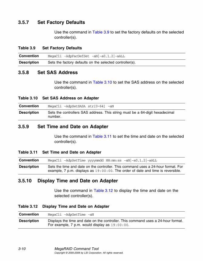
3-10 MegaRAID Command ToolCopyright © 2005-2008 by LSI Corporation. All rights reserved.
3.5.7 Set Factory Defaults
Use the command in Table 3.9 to set the factory defaults on the selected controller(s).
3.5.8 Set SAS Address
Use the command in Table 3.10 to set the SAS address on the selected controller(s).
3.5.9 Set Time and Date on Adapter
Use the command in Table 3.11 to set the time and date on the selected controller(s).
3.5.10 Display Time and Date on Adapter
Use the command in Table 3.12 to display the time and date on the selected controller(s).
Table 3.9 Set Factory Defaults
Convention MegaCli -AdpFacDefSet -aN|-a0,1,2|-aALL
Description Sets the factory defaults on the selected controller(s).
Table 3.10 Set SAS Address on Adapter
Convention MegaCli –AdpSetSASA str[0-64] -aN
Description Sets the controllers SAS address. This string must be a 64-digit hexadecimal number.
Table 3.11 Set Time and Date on Adapter
Convention MegaCli –AdpSetTime yyyymmdd HH:mm:ss -aN|-a0,1,2|-aALL
Description Sets the time and date on the controller. This command uses a 24-hour format. For example, 7 p.m. displays as 19:00:00. The order of date and time is reversible.
Table 3.12 Display Time and Date on Adapter
Convention MegaCli –AdpGetTime -aN
Description Displays the time and date on the controller. This command uses a 24-hour format. For example, 7 p.m. would display as 19:00:00.

Patrol Read-Related Adapter Properties 3-11Copyright © 2005-2008 by LSI Corporation. All rights reserved.
3.6 Patrol Read-Related Adapter Properties
You can use the commands in this section to select the settings for Patrol Read. A Patrol Read scans the system for possible drive errors that could lead to drive failure, then takes action to correct the errors. The goal is to protect data integrity by detecting drive failure before the failure can damage data. The corrective actions depend on the virtual drive configuration and the type of errors. Patrol Read affects performance; the more iterations there are, the greater the impact.
3.6.1 Set Patrol Read Options
Use the command in Table 3.13 on the selected controller(s) to set the Patrol Read options.
3.6.2 Set Patrol Read Delay Interval
Use the command in Table 3.14 on the selected controller(s) to set the time between Patrol Read iterations.
Table 3.13 Set Patrol Read Options
Convention MegaCli –AdpPR –Dsbl|EnblAuto|EnblMan|Start|Stop|Info -aN|-a0,1,2|-aALL
Description Sets Patrol Read options on a single controller, multiple controllers, or all controllers:-Dsbl: Disables Patrol Read for the selected controller(s).-EnblAuto: Enables Patrol Read automatically for the selected controller(s). This means Patrol Read will start automatically after the controller initialization is complete.-EnblMan: Enables Patrol Read manually for the selected controller(s). This means that Patrol Read does not start automatically; it has to be started manually by selecting the Start command.-Start: Starts Patrol Read for the selected controller(s).-Stop: Stops Patrol Read for the selected controller(s).-Info: Displays the following Patrol Read information for the selected controller(s):• Patrol Read operation mode• Patrol Read execution delay value• Patrol Read status

3-12 MegaRAID Command ToolCopyright © 2005-2008 by LSI Corporation. All rights reserved.
3.7 BIOS-Related Properties
You can use the commands in this section to select the settings for BIOS-related options.
3.7.1 Set or Display Bootable Virtual Drive ID
Use the command in Table 3.15 to set or display the ID of the bootable virtual drive.
Note: This option does not write a boot sector to the virtual drive. The operating system will not load if the boot sector is incorrect.
3.7.2 Select BIOS Status Options
Use the command in Table 3.16 to set the options for the BIOS status.
Table 3.14 Set Patrol Read Delay Interval
Convention MegaCli –AdpPRSetDelay –Val -aN|-a0,1,2|-aALL
Description Sets the time between Patrol Read iterations on a single controller, multiple controllers, or all controllers:-Val: Sets delay time between Patrol Read iterations. The value is time of delay in hours. A value of zero means no delay and an immediate restart.
Table 3.15 Bootable Virtual Drive ID
Convention MegaCli –AdpBootDrive {-Set –Lx} | -Get -aN|-a0,1,2|-aALL
Description Sets or displays the bootable virtual drive ID:-Set: Sets the virtual drive as bootable so that during the next reboot, the BIOS will look for a boot sector in the specified virtual drive.-Get: Displays the bootable virtual drive ID.
Table 3.16 Options for BIOS Status
Convention MegaCli –AdpBIOS -Enbl|-Dsbl|-Dsply| SOE | BE -aN|-a0,1,2|-aALL

Battery Backup Unit-Related Properties 3-13Copyright © 2005-2008 by LSI Corporation. All rights reserved.
3.8 Battery Backup Unit-Related Properties
You can use the commands in this section to select the settings for BBU-related options.
3.8.1 Display BBU Information
Use the command in Table 3.17 to display complete information about the BBU for the selected controller(s).
3.8.2 Display BBU Status Information
Use the command in Table 3.18 to display complete information about the status of the BBU, such as temperature and voltage, for the selected controller(s).
Description Sets BIOS options. The following are the settings you can select on a single controller, multiple controllers, or all controllers:-Enbl, -Dsbl, -Dsply: Enables, disables or displays the BIOS status on selected controller(s).-SOE: Stops on BIOS errors during POST for selected controller(s). When set to -SOE, the BIOS stops in case of a problem with the configuration. This gives you the option to enter the configuration utility to resolve the problem. This is available only when you enable the BIOS status.-BE: Bypasses BIOS errors during POST. This is available only when you enable the BIOS status.
Table 3.16 Options for BIOS Status (Cont.)
Table 3.17 Display BBU Information
Convention MegaCli -AdpBbuCmd -aN|-a0,1,2|-aALL
Description Displays complete information about the BBU, such as status, capacity information, design information, and properties.

3-14 MegaRAID Command ToolCopyright © 2005-2008 by LSI Corporation. All rights reserved.
3.8.3 Display BBU Capacity
Use the command in Table 3.19 to display the BBU capacity for the selected controller(s).
Table 3.18 Display BBU Status Information
Convention MegaCli -AdpBbuCmd -GetBbuStatus –aN|-a0,1,2|-aALL
Description Displays complete information about the BBU status, such as the temperature and voltage. The information displays in the following formats:BBU Status for Adapter: xxBattery Type: XXXXXX(string)Voltage: xx mVCurrent: xx mATemperature: xx C°Firmware Status: xxBattery state: xxGas Gauge Status:Fully Discharged: Yes/NoFully Charged: Yes/NoDischarging: Yes/NoInitialized: Yes/NoRemaining Time Alarm: Yes/NoRemaining Capacity Alarm: Yes/NoDischarge Terminated: Yes/NoOver Temperature: Yes/NoCharging Terminated: Yes/NoOver Charged: Yes/No
Additional status information displays differently for iBBU™ and BBU.For iBBU:Relative State of Charge: xxCharger System State: xxCharger System Ctrl: xxCharging Current: xx mAAbsolute State of Charge: xx%Max Error: xx%For BBU:Relative State of Charge: xxCharger Status: xxRemaining Capacity: xx mAhFull Charge Capacity: mAhisSOHGood: Yes/No

Battery Backup Unit-Related Properties 3-15Copyright © 2005-2008 by LSI Corporation. All rights reserved.
3.8.4 Display BBU Design Parameters
Use the command in Table 3.20 to display BBU design parameters for the selected controller(s).
3.8.5 Display Current BBU Properties
Use the command in Table 3.21 to display the current BBU properties for the selected controller(s).
Table 3.19 Display BBU Capacity Information
Convention MegaCli -AdpBbuCmd -GetBbuCapacityInfo –aN|-a0,1,2|-aALL
Description Displays BBU capacity information. The information displays in the following format:BBU Capacity Info for Adapter: xRelative State of Charge: xx%Absolute State of Charge: xx%Remaining Capacity: xx mAhFull Charge Capacity: xx mAhRun Time to Empty: xxx MinAverage Time to Empty: xxx MinAverage Time to Full: xxx MinCycle Count: xxMax Error: xx%
Table 3.20 Display BBU Design Parameters
Convention MegaCli -AdpBbuCmd -GetBbuDesignInfo –aN|-a0,1,2|-aALL
Description Displays information about the BBU design parameters. The information displays in the following formats:BBU Design Info for Adapter: xDate of Manufacture: mm/dd, yyyyDesign Capacity: xxx mAhDesign Voltage: mVSerial Number: 0xhhhhPack Stat Configuration: 0xhhhhManufacture Name: XXXXXX(String)Device Name: XXXXXX(String)Device Chemistry: XXXXXX(String)

3-16 MegaRAID Command ToolCopyright © 2005-2008 by LSI Corporation. All rights reserved.
3.8.6 Start BBU Learning Cycle
Use the command in Table 3.22 to start the BBU learning cycle on the selected controller(s). A learning cycle is a battery calibration operation performed by the controller periodically (approximately every three months) to determine the condition of the battery.
3.8.7 Place Battery in Low-Power Storage Mode
Use the command in Table 3.23 to place the battery into Low-Power Storage mode on the selected controller(s). This saves battery power consumption.
3.8.8 Set BBU Properties
Use the command in Table 3.24 to set the BBU properties on the selected controller(s) after reading from the file.
Table 3.21 Display Current BBU Properties
Convention MegaCli -AdpBbuCmd -GetBbuProperties –aN|-a0,1,2|-aALL
Description Displays current properties of the BBU. The information displays in the following formats:BBU Properties for Adapter: xAuto Learn Period: xxx SecNext Learn Time: xxxx SecLearn Delay Interval: xx HoursAuto-Learn Mode: Warn via Event/Disabled/Enabled
Table 3.22 Start BBU Learning Cycle
Convention MegaCli -AdpBbuCmd -BbuLearn -aN|-a0,1,2|-aALL
Description Starts the learning cycle on the BBU. No parameter is needed for this option.
Table 3.23 Place Battery in Low-Power Storage Mode
Convention MegaCli -AdpBbuCmd -BbuMfgSleep -aN|-a0,1,2|-aALL
Description Places the battery in Low-Power Storage mode. The battery automatically exits this state after 5 seconds.

Options for Displaying Logs Kept at Firmware Level 3-17Copyright © 2005-2008 by LSI Corporation. All rights reserved.
3.9 Options for Displaying Logs Kept at Firmware Level
Use the commands in this section to select the display settings for the event log and BBU terminal log, which are kept at the firmware level.
3.9.1 Event Log Management
Use the command in Table 3.25 to manage the event entries in the event log for the selected controller(s).
Table 3.24 Set BBU Properties
Convention MegaCli -AdpBbuCmd -SetBbuProperties -f<fileName> -aN|-a0,1,2|-aALL
Description Sets the BBU properties on the selected controller(s) after reading from the file. The information displays in the following formats:autoLearnPeriod = 1800SecnextLearnTime = 12345678Sec Seconds past 1/1/2000learnDelayInterval = 24hours Not greater than 7 daysautoLearnMode = 0 0 – Enabled, 1 - Disabled, 2 – WarnViaEvent.
Table 3.25 Event Log Management
Convention MegaCli –AdpEventLog –GetEventlogInfo | –GetEvents | GetSinceShutdown| GetSinceReboot | IncludeDeleted | {GetLatest <number>} -f <filename> | Clear -aN|-a0,1,2|-aALL | {GetCCIncon} -f <filename> -LX|-L0,2,5...|-LALL -aN|-a0,1,2|-aALL
Description Manages event log entries. The following are the settings you can select on a single controller, multiple controllers, or all controllers:-GetEventlogInfo: Displays overall event information such as total number of events, newest sequence number, oldest sequence number, shutdown sequence number, reboot sequence number, and clear sequence number.-GetEvents: Gets event log entry details. The information shown consists of total number of entries available at firmware side since the last clear and details of each entries of the error log. Start_entry specifies the initial event log entry when displaying the log.-GetSinceShutdown: Displays all of the events since last controller shutdown.-GetSinceReboot: Displays all of the events since last controller reboot.-IncludeDeleted: Displays all events, including deleted events.-GetLatest: Displays the latest number of events, if any exist. The event data will be writtent to the file in reverse order.-Clear: Clears the event log for the selected controller(s).-GetCCIncon:

3-18 MegaRAID Command ToolCopyright © 2005-2008 by LSI Corporation. All rights reserved.
3.9.2 Set BBU Terminal Logging
Use the command in Table 3.26 to set the BBU terminal logging for the selected controller(s).
3.10 Configuration-Related Options
You can specify the drives by using the Enclosure ID:Slot ID for SAS controllers. This assumes that all drives are connected to the controller through an enclosure. If the drives are not connected to an enclosure, it is assumed that they are connected to Enclosure 0. In this case there is no slot, so you can use the pdlist command to get the slot equivalent number. (This applies to all commands that use the Enclosure ID:Slot ID format.) MegaCLI expects the input in [:S] format for directly attached devices.
In the following options, [E0:S0, E1:S1] specifies the enclosure ID and slot ID for the drive.
3.10.1 Create a RAID Drive Group from All Unconfigured Good Drives
Use the command in Table 3.28 to create one RAID drive group out of all of the unconfigured good drives, and a hot spare, if desired. This is for RAID levels 0, 5, 6, 10, 50, or 60. All free drives are used to create a new drive group and, if desired, one hot spare drive. If it is not possible
Table 3.26 Set BBU Terminal Logging
Convention MegaCli –FwTermLog -Bbuoff |–BbuoffTemp|-Bbuon|-BbuGet|-Dsply | -Clear -aN| -a0,1,2|-aALL
Description Sets BBU terminal logging options. The following are the settings you can select on a single controller, multiple controllers, or all controllers:-Bbuoff: Turns off the BBU for firmware terminal logging. To turn off the BBU for logging, you have to shut down your system or turn off the power to the system after you run the command.–BbuoffTemp: Temporarily turns off the BBU for TTY (firmware terminal) logging. The battery will be turned on at the next reboot.-Bbuon: Turns on the BBU for TTY (firmware terminal) logging.-BbuGet: Displays the current BBU settings for TTY logging. -Dsply: Displays the TTY log (firmware terminal log) entries with details on the given controllers. The information shown consists of the total number of entries available at a firmware side.-Clear: Clears the TTY log.

Configuration-Related Options 3-19Copyright © 2005-2008 by LSI Corporation. All rights reserved.
to use all of the free drives, the command will abort with a related error level. If there are drives of different capacitys, the largest drive is used to make the hot spare.
Note: A virtual drive cannot have both SAS drives and SATA drives. Therefore, if the remaining free drives are SAS and SATA, a drive group cannot be created. The command will abort with a related error level.
3.10.2 Add RAID 0, 1, 5, or 6 Configuration
Use the command in Table 3.28 to add a RAID level 0, 1, 5, or 6 configuration to the existing configuration on the selected controller. For RAID levels 10, 50, or 60, see Section 3.10.3, “Add RAID 10, 50, or 60 Configuration.”
Table 3.27 Create a Drive Group from All of the Unconfigured Drives
Convention MegaCli –CfgLDAdd -R0|-R1|-R5|-R6[E0:S0,E1:S1,...] [WT | WB] [NORA | RA | ADRA] [Direct | Cached] [CachedBadBBU|NoCachedBadBBU] [ GHSP | DHSP] –spn x –ax | -Force
Description Creates one RAID drive group out of all of the unconfigured good drives, and a hot spare, if desired. This is for RAID levels 0, 5, 6, 10, 50, or 60. All free drives are u used to create a new drive group and, if desired, one hot spare drive.-Rx[E0:S0,...]: Specifies the RAID level and the drive enclosure/slot numbers used to construct a drive group. -WT (Write through), WB (Write back): Selects write policy.-NORA (No read ahead), RA (Read ahead), ADRA (Adaptive read ahead): Selects read policy.-Direct, -Cached: Selects cache policy.[{CachedBadBBU|NoCachedBadBBU }]: Specifies whether to use write cache when the BBU is bad.GHSP, DHSP: Specifies that the hot spare is global or dedicated.-spn: Specifies the maximum number of spans that a spanned drive group can have.-Force: Specifies that drive coercion is used to make the capacity of the drives compatible. Drive coercion is a tool for forcing drives of varying capacities to the same capacity so they can be used in a drive group.
Table 3.28 Add RAID 0, 1, 5, or 6 Configuration
Convention MegaCli –CfgLDAdd -R0|-R1|-R5|-R6[E0:S0,E1:S1,...] [WT | WB] [NORA | RA | ADRA] [Direct | Cached] [CachedBadBBU|NoCachedBadBBU] [-szXXXXXXXX [-szYYYYYYYY [... ]]] [-strpszM] [–Hsp[E5:S5,...]] [–afterLdX] -aN

3-20 MegaRAID Command ToolCopyright © 2005-2008 by LSI Corporation. All rights reserved.
Description Adds a RAID level 0, 1, 5, or 6 configuration to a specified controller. Even if no configuration is present, you have the option to write the configuration to the controller.
Note that RAID 1 supports up to 32 drives in a single span of 16 drive groups. RAID 1 requires an even number of drives, as data from one drive is mirrored to the other drive in each RAID 1 drive group.-Rx[E0:S0,...]: Specifies the RAID level and the drive enclosure/slot numbers to construct a drive group. -WT (Write through), WB (Write back): Selects write policy.-NORA (No read ahead), RA (Read ahead), ADRA (Adaptive read ahead): Selects read policy.-Cached, -Direct: Selects cache policy.[{CachedBadBBU|NoCachedBadBBU }]: Specifies whether to use write cache when the BBU is bad.-szXXXXXXXX: Specifies the capacity for the virtual drive, where XXXX is a decimal number of Mbytes. However, the actual capacity of the virtual drive can be smaller, because the driver requires the number of blocks from the drives in each virtual drive to be aligned to the stripe size. If multiple size options are specified, CT configures the virtual drives in the order of the options entered in the command line. The configuration of a particular virtual drive will fail if the remaining capacity of the drive group is too small to configure the virtual drive with the specified capacity. This option can also be used to create a configuration on the free space available in the drive group.-strpszM: Specifies the stripe size, where the stripe size values are 8, 16, 32, 64, 128, 256, 512, or 1024 KBytes.Hsp[E5:S5,...]: Creates hot spares when you create the configuration. The new hot spares will be dedicated to the virtual drive used in creating the configuration. This option does not allow you to create global hot spares. To create global hot spares, you must use the -PdHsp command with proper subcommands.You can also use this option to create a configuration on the free space available in the virtual drive. You can specify which free slot should be used by specifying the -AfterLdX: This command is optional. By default, the application uses the first free slot available in the virtual drive. This option is valid only if the virtual drive is already used for configuration.
Table 3.28 Add RAID 0, 1, 5, or 6 Configuration (Cont.)

Configuration-Related Options 3-21Copyright © 2005-2008 by LSI Corporation. All rights reserved.
3.10.3 Add RAID 10, 50, or 60 Configuration
Use the command in Table 3.29 to add a RAID 10, RAID 50, or RAID 60 configuration to the existing configuration on the selected controller. For RAID levels 0, 1, 5, or 6, see Section 3.10.2, “Add RAID 0, 1, 5, or 6 Configuration.”
3.10.4 Clear the Existing Configuration
Use the command in Table 3.30 to clear the existing configuration on the selected controller(s).
Table 3.29 Add RAID 10, 50, or 60 Configuration
Convention MegaCli –CfgSpanAdd -aN|-a0,1,2|-aALL -R10|-R50|R60 –Array0[E0:S0,E1:S1,...] –Array1[E0:S0,E1:S1,...] [...] [WT | WB] [NORA | RA | ADRA] [Direct | Cached] [CachedBadBBU|NoCachedBadBBU] [-szXXXXXXXX [-szYYYYYYYY [... ]]] [-strpszM] [–afterLdX] -aN
Description Creates a RAID level 10, 50, or 60 (spanned) configuration from the specified drive groups. Even if no configuration is present, you must use this option to write the configuration to the controller.
Note that RAID 10 supports up to eight spans with a maximum of 32 drives in each span. (There are factors, such as the type of controller, that limit the number of drives you can use.) RAID 10 requires an even number of drives, as data from one drive is mirrored to the other drive in each RAID 1 drive group. You can have an even or odd number of spans.
Multiple drive groups are specified using the –ArrayX[E0:S0,...] option. (Note that X starts from 0, not 1.) All of the drive groups must have the same number of drives. At least two drive groups must be provided. The order of options {WT |WB} {NORA | RA | ADRA} {Direct | Cached} is flexible.
The size option, -szXXXXXXXX, can be accepted to allow slicing in the spanned drive groups if the controller supports this feature. The [–afterLdX] option is accepted if the size option is accepted. CT exits and does not create a configuration if the size or the afterLd option is specified but the controller does not support slicing in the spanned drive groups.
Table 3.30 Clear Existing Configuration
Convention MegaCli –CfgClr -aN|-a0,1,2|-aALL
Description Clears the existing configuration.

3-22 MegaRAID Command ToolCopyright © 2005-2008 by LSI Corporation. All rights reserved.
3.10.5 Save the Configuration on the Adapter
Use the command in Table 3.31 to save the configuration for the selected controller(s) to the given filename.
3.10.6 Restore the Configuration Data from File
Use the command in Table 3.32 to read the configuration from the file and load it on the selected controller(s). You can restore the read/write properties and RAID configuration using hot spares.
3.10.7 Manage Foreign Configuration Information
Use the command in Table 3.33 to manage configurations from other controllers, called foreign configurations, for the selected controller(s). You can scan, preview, import, and clear foreign configurations.
Note: The actual status of virtual drives and drives can differ from the information displayed in the –Scan option. LSI suggests that you run –Preview before you import a foreign configuration.
Table 3.31 Save Configuration on the Adapter
Convention MegaCli –CfgSave –f FileName -aN
Description Saves the configuration for the selected controller(s) to the given filename.
Table 3.32 Restore Configuration Data from File
Convention MegaCli –CfgRestore –f FileName -aN
Description Reads the configuration from the file and loads it on the controller. MegaCLI can store or restore all read and write controller properties, all read and write properties for virtual drives, and the RAID configuration including hot spares. Note the following:• MegaCLI does not validate the setup when restoring the RAID configuration.• The -CfgSave option stores the configuration data and controller properties in the
file. Configuration data has only the device ID and sequence number information of the drives used in the configuration. The CfgRestore option will fail if the same device IDs of the drives are not present.

Configuration-Related Options 3-23Copyright © 2005-2008 by LSI Corporation. All rights reserved.
3.10.8 Delete Specified Virtual Drive(s)
Use the command in Table 3.34 to delete one, multiple, or all virtual drives on the selected controller(s).
3.10.9 Display the Free Space
Use the command in Table 3.35 to display the free space that is available to use for configuration on the selected controller(s).
Table 3.33 Manage Foreign Configuration Information
Convention MegaCli –CfgForeign –Scan | {-Preview | –Dsply| -Import | -Clear [FID]} -aN|-a0,1,2|-aALL
Description Manages foreign configurations. The options for this command are:-Scan: Scans and displays available foreign configurations.-Preview: Provides a preview of the imported foreign configuration. The foreign configuration ID (FID) is optional.-Dsply: Displays the foreign configuration.-Import: Imports the foreign configuration. The FID is optional.-Clear [FID]: Clears the foreign configuration. The FID is optional.
Table 3.34 Delete Specified Virtual Drives
Convention MegaCli –CfgLDDel –Lx|-L0,1,2|-Lall -aN|-a0,1,2|-aALL
Description Deletes the specified virtual drive(s) on the selected controller(s). You can delete one virtual drive, multiple virtual drives, or all of the selected virtual drives on selected controller(s).
Table 3.35 Display Free Space
Convention MegaCli –CfgFreeSpaceInfo -aN|-a0,1,2|-aALL
Description Displays all of the free space available for configuration on the selected controller(s). The information displayed includes the number of drive groups, the number of spans in each drive group, the number of free space slots in each drive group, the start block, and the size (in both blocks and megabytes) of each free space slot.

3-24 MegaRAID Command ToolCopyright © 2005-2008 by LSI Corporation. All rights reserved.
3.11 Virtual Drive-Related Options
You can use the commands in this section to select settings for the virtual drives and perform actions on them.
3.11.1 Display Virtual Drive Information
Use the command in Table 3.36 to display virtual drive information for the selected controller(s).
3.11.2 Change the Virtual Drive Cache and Access Parameters
Use the command in Table 3.37 to change the cache policy and access policy for the virtual drive(s) on the selected controller(s).
Table 3.36 Display Virtual Drive Information
Convention MegaCli –LDInfo –Lx|-L0,1,2|-Lall -aN|-a0,1,2|-aALL
Description Displays information about the virtual drive(s) on the selected controller(s). This information includes the name, RAID level, RAID level qualifier, capacity in megabytes, state, stripe size, number of drives, span depth, cache policy, access policy, and ongoing activity progress, if any, including initialization, background initialization, consistency check, and reconstruction.
Table 3.37 Change Virtual Drive Cache and Access Parameters
Convention MegaCli –LDSetProp WT | WB|NORA |RA | ADRA|-Cached|Direct|CachedBadBBU|NoCachedBadBBU} | -RW|RO|Blocked | {-Name nameString} | -EnDskCache|DisDskCache –Lx| -L0,1,2|-Lall -aN|-a0,1,2|-aALL
Description Allows you to change the following virtual drive parameters:-WT (Write through), WB (Write back): Selects write policy.-NORA (No read ahead), RA (Read ahead), ADRA (Adaptive read ahead): Selects read policy.-Cached, -Direct: Selects cache policy.-CachedBadBBU|NoCachedBadBBU : Specifies whether to use write cache when the BBU is bad.-RW, -RO, Blocked: Selects access policy.-EnDskCache: Enables drive cache.-DisDskCache: Disables drive cache.

Virtual Drive-Related Options 3-25Copyright © 2005-2008 by LSI Corporation. All rights reserved.
3.11.3 Display the Virtual Drive Cache and Access Parameters
Use the command in Table 3.38 to display cache and access parameters for the virtual drive(s) on the selected controller(s).
3.11.4 Manage Virtual Drives Initialization
Use the command in Table 3.39 to manage initialization of the virtual drive(s) on the selected controller(s).
Table 3.38 Display Virtual Drive Cache and Access Parameters
Convention MegaCli –LDGetProp -Cache | -Access | -Name | -DskCache -Lx|-L0,1,2| -Lall -aN|-a0,1,2|-aALL
Description Displays the cache and access policies of the virtual drive(s):-Cache: -Cached, Direct: Displays cache policy.-WT (Write through), WB (Write back): Selects write policy.-NORA (No read ahead), RA (Read ahead), ADRA (Adaptive read ahead): Selects read policy.-Access: -RW, -RO, Blocked: Displays access policy.-DskCache: Displays drive cache policy.
Table 3.39 Manage Virtual Drive Initialization
Convention MegaCli –LDInit {–Start [Fast | Full]} |-Abort|–ShowProg|-ProgDsply-Lx|-L0,1,2|-Lall -aN|-a0,1,2|-aALL
Description Allows you to select the following actions for virtual drive initialization:-Start: Starts the initialization (writing 0s) on the virtual drive(s) and displays the progress (this is optional). The fast initialization option initializes the first and last 8 Mbyte areas on the virtual drive. The full option allows you to initialize the entire virtual drive.-Abort: Aborts the ongoing initialization on the virtual drive(s). -ShowProg: Displays the snapshot of the ongoing initialization, if any.-ProgDsply: Displays the progress of the ongoing initialization. The routine continues to display the progress until at least one initialization is completed or a key is pressed.

3-26 MegaRAID Command ToolCopyright © 2005-2008 by LSI Corporation. All rights reserved.
3.11.5 Manage a Consistency Check
Use the command in Table 3.40 to manage a data consistency check (CC) on the virtual drives for the selected controller(s).
3.11.6 Manage a Background Initialization
Use the command in Table 3.41 to enable, disable, or suspend background initialization (BGI), as well as display initialization progress on the selected controller(s).
Table 3.40 Manage Consistency Check
Convention MegaCli –LDCC –Start|-Abort|–ShowProg|-ProgDsply –Lx|-L0,1,2|-Lall -aN|-a0,1,2|-aALL
Description Allows you to select the following actions for a data CC:-Start: Starts a CC on the virtual drive(s), then displays the progress (optional) and time remaining.-Abort: Aborts an ongoing CC on the virtual drive(s). -ShowProg: Displays a snapshot of an ongoing CC.-ProgDsply: Displays ongoing CC progress. The progress displays until at least one CC is completed or a key is pressed.
Table 3.41 Manage Background Initialization
Convention MegaCli –LDBI -Enbl|-Dsbl|GetSetting|-ShowProg|-ProgDsply –Lx|-L0,1,2|-Lall -aN|-a0,1,2|-aALL
Description Manages background initialization options. The following are the background initialization settings you can select on a single controller, multiple controllers, or all controllers:-Enbl, -Dsbl: Enables or disables the background initialization on the selected controller(s).-ProgDsply: Displays an ongoing background initialization in a loop. This function completes only when all background initialization processes complete or you press a key to exit.-ShowProg: Displays the current progress value.- GetSetting: Displays current background initialization setting (Enabled or Disabled).

Virtual Drive-Related Options 3-27Copyright © 2005-2008 by LSI Corporation. All rights reserved.
3.11.7 Perform a Virtual Drive Reconstruction
Use the command in Table 3.42 to perform a reconstruction of the virtual drive(s) on the selected controller(s).
3.11.8 Display Information about Virtual Drives and Drives
Use the command in Table 3.43 to display information about the virtual drives and drives for the selected controller(s), such as the number of virtual drives, RAID level, and drive capacity.
3.11.9 Display the Number of Virtual Drives
Use the command in Table 3.44 to display the number of virtual drives attached to the controller.
Table 3.42 Virtual Drive Reconstruction
Convention MegaCli –LDRecon {–Start –Rx [Add | Rmv PhysDrv[E0:S0,E1:S1,...] ] } |–ShowProg|-ProgDsply –Lx –aN
Description Controls and manages virtual drive reconstruction. The following are the virtual drive reconstruction settings you can select on a single controller:-Start: Starts a reconstruction of the selected virtual drive to a new RAID level.-Rx: Changes the RAID level of the virtual drive when you start reconstruction. You might need to add or remove a drive to make this possible.-Start –Add PhysDrv[E0:S0,E1:S1....]: Adds listed drives to the virtual drive and starts reconstruction on the selected virtual drive. -Start –Rmv PhysDrv[E0:S0,E1:S1....]: Removes one drive from the existing virtual drives and starts a reconstruction.-ShowProg: Displays a snapshot of the ongoing reconstruction process.-ProgDsply: Allows you to view the ongoing reconstruction. The routine continues to display progress until at least one reconstruction is completed or a key is pressed.
Table 3.43 Display Virtual Drive and Drive Information
Convention MegaCli –LDPDInfo -aN|-a0,1,2|-aALL
Description Displays information about the present virtual drive(s) and drive(s) on the selected controller(s). Displays information including the number of virtual drives, the RAID level of the virtual drives, and drive capacity information, which includes raw capacity, coerced capacity, uncoerced capacity, and the SAS address.
Table 3.44 Display Number of Virtual Drives
Convention MegaCli –LDGetNum –aN|-a0,1,2|-aALL

3-28 MegaRAID Command ToolCopyright © 2005-2008 by LSI Corporation. All rights reserved.
3.12 Drive-Related Options
You can use the commands in this section to select settings for the drives and perform actions on them.
3.12.1 Display Drive Information
Use the command in Table 3.45 to display information about the drives on the selected controller(s).
3.12.2 Set the Drive State to Online
Use the command in Table 3.46 to set the state of a drive to Online. In an online state, the drive is working normally and is a part of a configured virtual drive.
3.12.3 Set the Drive State to Offline
Use the command in Table 3.47 to set the state of a drive to Offline. In the offline state, the virtual drive is not available to the RAID controller.
Description Displays the number of virtual drives attached to the controller. The return value is the number of virtual drives.
Table 3.44 Display Number of Virtual Drives (Cont.)
Table 3.45 Display Drive Information
Convention MegaCli –PDInfo -PhysDrv[E0:S0,E1:S1....] -aN|-a0,1,2|-aALL
Description Provides information about the drives connected to the enclosure and controller slot. This includes information such as the enclosure number, slot number, device ID, sequence number, drive type, capacity (if a drive), foreign state, firmware state, and inquiry data.
For SAS devices, this includes additional information such as the SAS address of the drive. For SAS expanders, this includes additional information such as the number of devices connected to the expander.
Table 3.46 Set Drive State to Online
Convention MegaCli –PDOnline -PhysDrv[E0:S0,E1:S1....] -aN|-a0,1,2|-aALL
Description Changes the drive state to Online.

Drive-Related Options 3-29Copyright © 2005-2008 by LSI Corporation. All rights reserved.
3.12.4 Change the Drive State to Unconfigured Good
Use the command in Table 3.48 to change the state of a drive from Unconfigured-Bad to Unconfigured-Good.
3.12.5 Change Drive State
Use the command in Table 3.49 to change the drive state, as it relates to hot spares, and to associate the drive to an enclosure and virtual drive for the selected controller(s).
Table 3.47 Set Drive State to Offline
Convention MegaCli –PDOffline -PhysDrv[E0:S0,E1:S1....] -aN|-a0,1,2|-aALL
Description Changes the drive state to Offline.
Table 3.48 Change Drive State to Unconfigured Good
Convention MegaCli –PDMakeGood -PhysDrv[E0:S0,E1:S1....] -aN|-a0,1,2|-aALL
Description Changes the drive state to Offline.
Table 3.49 Change Drive State
Convention MegaCli –PDHSP {–Set [{-Dedicated -ArrayN |-Array0,1...}] [-EnclAffinity] [-nonRevertible] } | -Rmv -PhysDrv[E0:S0,E1:S1,...] -aN|-a0,1,2|-aALL
Description Changes the drive state (as it relates to hot spares) and associates the drive to an enclosure and virtual drive on a single controller, multiple controllers, or all controllers:-Set: Changes the drive state to dedicated hot spare for the enclosure.-Rmv: Changes the drive state to ready (removes the hot spare).-EnclAffinity: Associates the hot spare to a selected enclosure.-Array0: Dedicates the hot spare to a specific virtual drive.
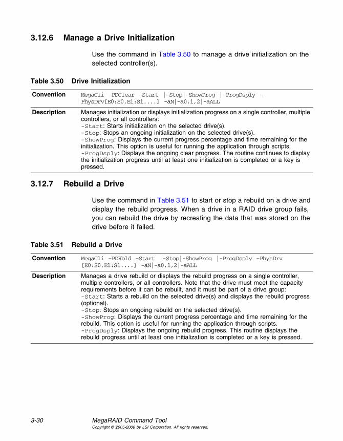
3-30 MegaRAID Command ToolCopyright © 2005-2008 by LSI Corporation. All rights reserved.
3.12.6 Manage a Drive Initialization
Use the command in Table 3.50 to manage a drive initialization on the selected controller(s).
3.12.7 Rebuild a Drive
Use the command in Table 3.51 to start or stop a rebuild on a drive and display the rebuild progress. When a drive in a RAID drive group fails, you can rebuild the drive by recreating the data that was stored on the drive before it failed.
Table 3.50 Drive Initialization
Convention MegaCli –PDClear -Start |-Stop|-ShowProg |-ProgDsply -PhysDrv[E0:S0,E1:S1....] -aN|-a0,1,2|-aALL
Description Manages initialization or displays initialization progress on a single controller, multiple controllers, or all controllers:-Start: Starts initialization on the selected drive(s).-Stop: Stops an ongoing initialization on the selected drive(s).-ShowProg: Displays the current progress percentage and time remaining for the initialization. This option is useful for running the application through scripts.-ProgDsply: Displays the ongoing clear progress. The routine continues to display the initialization progress until at least one initialization is completed or a key is pressed.
Table 3.51 Rebuild a Drive
Convention MegaCli –PDRbld –Start |-Stop|-ShowProg |-ProgDsply –PhysDrv [E0:S0,E1:S1....] -aN|-a0,1,2|-aALL
Description Manages a drive rebuild or displays the rebuild progress on a single controller, multiple controllers, or all controllers. Note that the drive must meet the capacity requirements before it can be rebuilt, and it must be part of a drive group:-Start: Starts a rebuild on the selected drive(s) and displays the rebuild progress (optional).-Stop: Stops an ongoing rebuild on the selected drive(s).-ShowProg: Displays the current progress percentage and time remaining for the rebuild. This option is useful for running the application through scripts.-ProgDsply: Displays the ongoing rebuild progress. This routine displays the rebuild progress until at least one initialization is completed or a key is pressed.

Drive-Related Options 3-31Copyright © 2005-2008 by LSI Corporation. All rights reserved.
3.12.8 Locate the Drive(s) and Activate LED
Use the command in Table 3.52 to locate the drive(s) for the selected controller(s) and activate the drive activity LED.
3.12.9 Mark the Configured Drive as Missing
Use the command in Table 3.53 to mark the configured drive as missing for the selected controller(s).
3.12.10 Display the Drives in Missing Status
Use the command in Table 3.53 to mark the configured drive as missing for the selected controller(s)
.
3.12.11 Replace the Configured Drives and Start an Automatic Rebuild
Use the command in Table 3.55 to replace configured drive(s) and start an automatic rebuild of the drive for the selected controller(s).
Table 3.52 Locate Drive and Activate LED
Convention MegaCli –PDLocate –PhysDrv[E0:S0,E1:S1....] -aN|-a0,1,2|-aALL
Description Locates the drive(s) for the selected controller(s) and activates the drive activity LED.
Table 3.53 Mark Configured Drive as Missing
Convention MegaCli –PDMarkMissing –PhysDrv[E0:S0,E1:S1....] -aN|-a0,1,2|-aALL
Description Marks the configured drive as missing for the selected controller(s).
Table 3.54 Display Drives in Missing Status
Convention MegaCli –PDGetMissing -aN|-a0,1,2|-aALL
Description Displays the drive(s) in missing status. The format is:
No Row Column SizeExpected(MB)0 x y zzzzzzzzz…Where x is the index to the drive groups, y is the index to the drive in that drive group, and zzzzzz is the minimum capacity of the drive that can be used as a replacement.
Table 3.55 Replace Configured Drive(s) and Start Automatic Rebuild
Convention MegaCli –PDReplaceMissing –PhysDrv[E0:S0,E1:S1....] -ArrayX -RowY -aN

3-32 MegaRAID Command ToolCopyright © 2005-2008 by LSI Corporation. All rights reserved.
3.12.12 Prepare the Unconfigured Drive for Removal
Use the command in Table 3.56 to prepare the unconfigured drive(s) for removal from the selected controller(s).
3.12.13 Display Total Number of Drives
Use the command in Table 3.57 to display the total number of drives attached to an controller. Drives can be attached directly or through enclosures.
3.12.14 Display List of Physical Devices
Use the command in Table 3.58 to display a list of the physical devices connected to the selected controller(s).
Description Replaces the configured drives that are identified as missing and then starts an automatic rebuild.
Table 3.55 Replace Configured Drive(s) and Start Automatic Rebuild (Cont.)
Table 3.56 Prepare Unconfigured Drive(s) for Removal
Convention MegaCli –PDPrpRmv [-Undo] – PhysDrv[E0:S0,E1:S1....] -aN|-a0,1,2|-aALL
Description Prepares unconfigured drive(s) for removal. The firmware will spin down this drive. The drive state is set to unaffiliated, which marks it as offline even though it is not a part of configuration.The -Undo option undoes this operation. If you select undo, the firmware marks this drive as unconfigured good.
Table 3.57 Display Number of Drives Attached to an Adapter
Convention MegaCli –PDGetNum –aN|-a0,1,2|-aALL
Description Displays the total number of drives attached to an controller. Drives can be attached directly or through enclosures. The return value is the number of drives.
Table 3.58 Display List of Physical Devices Attached to Adapter(s)
Convention MegaCli –PDList –aN|-a0,1..|-aAll
Description Displays information about all drives and other devices connected to the selected controller(s). This includes information such as the drive type, capacity (if a drive), serial number, and firmware version of the device. For SAS devices, this includes additional information such as the SAS address of the device. For SAS expanders, this includes additional information such as the number of drives connected to the expander.

Enclosure-Related Options 3-33Copyright © 2005-2008 by LSI Corporation. All rights reserved.
3.13 Enclosure-Related Options
The commands in this section are used for enclosures.
Use the command in Table 3.59 to display enclosure information for selected controller(s).
3.14 Flashing the Firmware
The options in this section describe the functionality of the existing flash application. The firmware flash options do not require input from the user.
3.14.1 Flash the Firmware with the ROM File
Use the command in Table 3.60 to flash the firmware with the ROM file specified at the command line for the selected controller(s).
Table 3.59 Display Enclosure Information
Convention MegaCli –EncInfo -aN|-a0,1,2|-aALL
Description Displays information about the enclosure for the selected controller(s).
Table 3.60 Flash Firmware with ROM File
Convention MegaCli –AdpFwFlash –f filename [-NoSigChk] [-NoVerChk]-aN|-a0,1,2|-aALL
Description Flashes the firmware with the ROM file specified at the command line.The –NoSigChk option forces the application to flash the firmware even if the check word on the file does not match the required check word for the controller. This option flashes the firmware only if the existing firmware version on the controller is lower than the version on the ROM image. If you specify –NoVerChk, also, the application flashes the controller firmware without checking the version of the firmware image. The version check applies only to the firmware (APP.ROM) version.This command also supports the “Mode 0” flash functionality. For Mode 0 flash, the controller number is not valid. There are two possible methods:• Select which controller to flash after the controllers are detected.• Flash the firmware on all present controllers. XML output data is generated by this option.
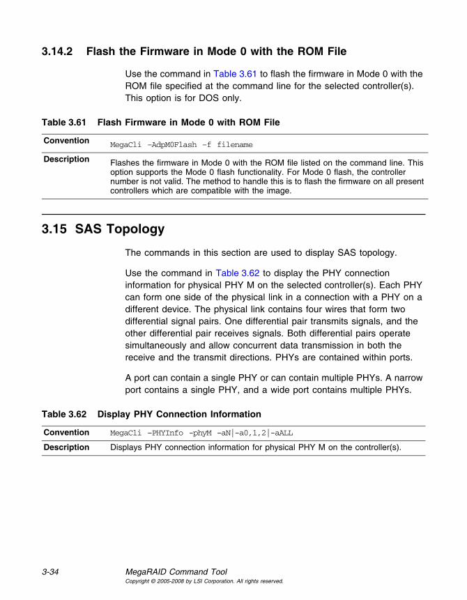
3-34 MegaRAID Command ToolCopyright © 2005-2008 by LSI Corporation. All rights reserved.
3.14.2 Flash the Firmware in Mode 0 with the ROM File
Use the command in Table 3.61 to flash the firmware in Mode 0 with the ROM file specified at the command line for the selected controller(s). This option is for DOS only.
3.15 SAS Topology
The commands in this section are used to display SAS topology.
Use the command in Table 3.62 to display the PHY connection information for physical PHY M on the selected controller(s). Each PHY can form one side of the physical link in a connection with a PHY on a different device. The physical link contains four wires that form two differential signal pairs. One differential pair transmits signals, and the other differential pair receives signals. Both differential pairs operate simultaneously and allow concurrent data transmission in both the receive and the transmit directions. PHYs are contained within ports.
A port can contain a single PHY or can contain multiple PHYs. A narrow port contains a single PHY, and a wide port contains multiple PHYs.
Table 3.61 Flash Firmware in Mode 0 with ROM File
Convention MegaCli –AdpM0Flash –f filename
Description Flashes the firmware in Mode 0 with the ROM file listed on the command line. This option supports the Mode 0 flash functionality. For Mode 0 flash, the controller number is not valid. The method to handle this is to flash the firmware on all present controllers which are compatible with the image.
Table 3.62 Display PHY Connection Information
Convention MegaCli –PHYInfo -phyM –aN|-a0,1,2|-aALL
Description Displays PHY connection information for physical PHY M on the controller(s).

Diagnostic-Related Options 3-35Copyright © 2005-2008 by LSI Corporation. All rights reserved.
3.16 Diagnostic-Related Options
The commands in this section are used to run diagnostic tests.
3.16.1 Start Adapter Diagnostics
Use the command in Table 3.63 to start the controller diagnostic for a set amount of time.
3.16.2 Start Battery Test
Use the command in Table 3.64 to start the battery test. This command requires a system reboot.
3.16.3 Start NVRAM Diagnostic
Use the command in Table 3.65 to start the controller NVRAM diagnostic for a set amount of time. This option is for DOS only.
Table 3.63 Start Diagnostics Setting
Convention MegaCli –AdpDiag [val] –aN|-a0,1,2|-aALL
Description Sets the amount of time for the controller diagnostic to run.
Table 3.64 Start Battery Test
Convention MegaCli –AdpBatTest –aN|-a0,1,2|-aALL
Description Starts the battery test. This command requires that you turn off the power to the system, and then turn on the power and reboot the system.
Table 3.65 Start NVRAM Diagnostic
Convention MegaCli –AdpNVRAM {-Read|-Write -ffilename}|–Clear [-StartOffset 0xXXXX] [-EndOffset 0xXXXX] aN
Description Starts the NVRAM diagnostic.-Read: Reads the content in NVRAM and writes the data to file filename.-Write: Reads data from file filename and writes to NVRAM.-Clear: Writes 0 to NVRAM at the specified range from start offset to end offset.-StartOffset/-EndOffset: Specifies the start offset and/or end offset in NVRAM. If you do not use the -StartOffset and -EndOffset options, the default StartOffset is 0 and the default EndOffset is the end of actual NVRAM size.

3-36 MegaRAID Command ToolCopyright © 2005-2008 by LSI Corporation. All rights reserved.
3.17 Miscellaneous Options
The commands in this section are used to display various information.
3.17.1 Display the MegaCLI Version
Use the command in Table 3.66 to display the version number of the MegaCLI utility.
3.17.2 Display Help for MegaCLI
Use the command in Table 3.67 to display help information for the MegaCLI utility.
Table 3.66 Display MegaCLI Version
Convention MegaCli –v
Description Displays the version number of the MegaCLI utility.
Table 3.67 Display Help for MegaCLI
Convention MegaCli –h|–Help|?
Description Displays help for the MegaCLI utility.
MegaRAID SAS Software User’s Guide 4-1Copyright © 2005-2008 by LSI Corporation. All rights reserved.
Chapter 4MegaRAID Storage Manager Overview and Installation
This chapter provides a brief overview of the MegaRAID Storage Manager (MSM) software and explains how to install it on the supported operating systems. This chapter has the following sections:
• Section 4.1, “Overview”
• Section 4.2, “Hardware and Software Requirements”
• Section 4.3, “Installation”
4.1 Overview
MegaRAID Storage Manager software enables you to configure, monitor, and maintain storage configurations on LSI SAS controllers. The MegaRAID Storage Manager graphical user interface (GUI) makes it easy for you to create and manage storage configurations.
4.1.1 Creating Storage Configurations
MegaRAID Storage Manager software enables you to easily configure the controllers, drives, and virtual drives on your workstation or server. The Configuration Wizard greatly simplifies the process of creating drive groups and virtual drives.
You can use the Configuration Wizard Auto Configuration mode to automatically create the best possible configuration with the available hardware. You can use the Guided Configuration mode, which asks you a few brief questions about the configuration, and then creates it for you. Or you can use the Manual Configuration mode, which gives you complete control over all aspects of the storage configuration.
The Reconstruction Wizard enables you to increase or reduce the capacity of a virtual drive and to change the RAID level of a drive group.

4-2 MegaRAID Storage Manager Overview and InstallationCopyright © 2005-2008 by LSI Corporation. All rights reserved.
4.1.2 Monitoring Storage Devices
MegaRAID Storage Manager software displays the status of controllers, virtual drives, and drives on the workstation or server that you are monitoring. System errors and events are recorded in an event log file and are displayed on the screen. Special device icons appear on the screen to notify you of drive failures and other events that require immediate attention.
4.1.3 Maintaining Storage Configurations
You can use MegaRAID Storage Manager software to perform system maintenance tasks such as running patrol read operations, updating firmware, and running consistency checks on drive groups that support redundancy.
4.2 Hardware and Software Requirements
The hardware requirements for MegaRAID Storage Manager software are as follows:
• PC-compatible computer with an IA-32 (32-bit) Intel Architecture processor or an EM64T (64-bit) processor and at least 128 Mbytes of system memory (256 Mbytes recommended)
• Drive with at least 50 Mbytes available free space
The supported operating systems for the MegaRAID Storage Manager software are as follows:
• Microsoft Windows 2000, Microsoft Windows Server 2003, Microsoft Windows XP, and Microsoft Windows Vista
• Red Hat Linux 3.0, 4.0, and 5.0
• SUSE SLES 9 and 10, with latest updates and service packs
Refer to your server documentation and to the operating system documentation for more information on hardware and operating system requirements.

Installation 4-3Copyright © 2005-2008 by LSI Corporation. All rights reserved.
4.3 Installation
This section explains how to install (or reinstall) MegaRAID Storage Manager software on your workstation or server for the supported operating systems: Microsoft Windows, Red Hat Linux, and SUSE Linux.
4.3.1 Installing MegaRAID Storage Manager Software on Microsoft Windows
Follow these steps if you need to install MegaRAID Storage Manager software on a system running Microsoft Windows 2000, Microsoft Windows Server 2003, Microsoft Windows XP, or Microsoft Windows Vista:
1. Insert the MegaRAID Storage Manager software installation CD in the CD-ROM drive.
If necessary, find and double-click the setup.exe file to start the installation program.
2. When the Welcome screen appears, click Next.
If MegaRAID Storage Manager software is already installed on this system, the Program Maintenance screen appears. Read the screen text and select Modify, Repair, or Remove.
3. When the next screen appears, read and accept the user license, and click Next.
The Customer Information screen appears, as shown in Figure 4.1.

4-4 MegaRAID Storage Manager Overview and InstallationCopyright © 2005-2008 by LSI Corporation. All rights reserved.
Figure 4.1 Customer Information Screen
4. Enter your user name and organization name. In the bottom part of the screen, select an installation option:
– If you select All users, any user with administrative privileges can use this version of MegaRAID Storage Manager software to view or change storage configurations.
– If you select Only for current user, the MegaRAID Storage Manager shortcuts and associated icons will be available only to the user with this user name.
5. Click Next to continue.
6. On the next screen, accept the default Destination Folder, or click Change to select a different destination folder. Click Next to continue.
The Setup Type screen appears, as shown in Figure 4.2.

Installation 4-5Copyright © 2005-2008 by LSI Corporation. All rights reserved.
Figure 4.2 Setup Type Screen
7. Select one of the Setup options. The options are fully explained in the screen text.
– Normally, you would select Complete if you are installing MegaRAID Storage Manager software on a server.
– Select Custom Installation if you want to select individual program components.
8. Click Next to continue.
If you selected Custom Installation as your setup option, the second Setup Type screen appears, as shown in Figure 4.3.
If you select Complete as your setup option, the Installation Wizard is ready to install MSM. To begin installation, click on Install on the next screen that appears.

4-6 MegaRAID Storage Manager Overview and InstallationCopyright © 2005-2008 by LSI Corporation. All rights reserved.
Figure 4.3 Setup Type Screen
9. Select one of the custom setup options. The options are fully explained in the screen text.
– Select Client if you are installing MegaRAID Storage Manager software on a PC that will be used to view and configure servers over a network. To begin installation, click on Install on the next screen that appears.
In the Client mode of installation, MSM installs only client-related components, such as MSM GUI, and monitor configurator. Use this mode when you want to manage and monitor servers remotely. When you install MSM in Client mode on a laptop or a desktop, you can log in to a specific server by providing the IP address.
– Select Server to install only those components required for remote server management. To begin installation, click on Install on the next screen that appears.
– Select StandAlone if you will use MegaRAID Storage Manager software to create and manage storage configurations on a standalone workstation. To begin installation, click on Install on the next screen that appears.
– Select Custom if you want to specify individual program features to install.
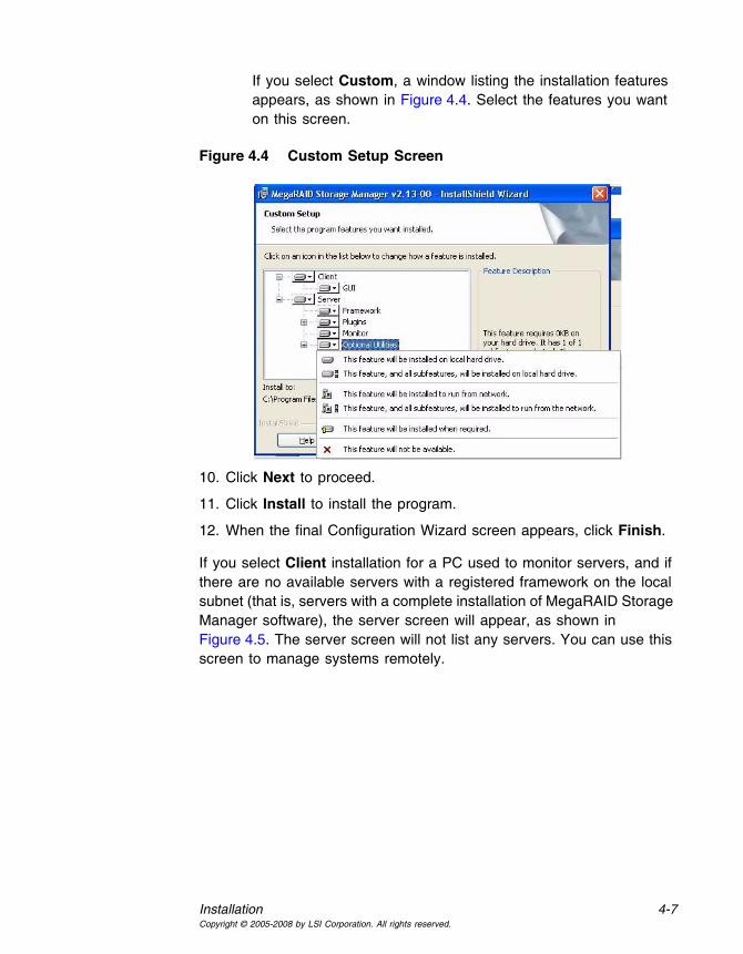
Installation 4-7Copyright © 2005-2008 by LSI Corporation. All rights reserved.
If you select Custom, a window listing the installation features appears, as shown in Figure 4.4. Select the features you want on this screen.
Figure 4.4 Custom Setup Screen
10. Click Next to proceed.
11. Click Install to install the program.
12. When the final Configuration Wizard screen appears, click Finish.
If you select Client installation for a PC used to monitor servers, and if there are no available servers with a registered framework on the local subnet (that is, servers with a complete installation of MegaRAID Storage Manager software), the server screen will appear, as shown in Figure 4.5. The server screen will not list any servers. You can use this screen to manage systems remotely.

4-8 MegaRAID Storage Manager Overview and InstallationCopyright © 2005-2008 by LSI Corporation. All rights reserved.
Figure 4.5 Server Screen
4.3.2 Installing MegaRAID Storage Manager Software for Linux
Follow these steps if you need to install MegaRAID Storage Manager software on a system running Red Hat Linux or SUSE Linux:
1. Copy the MSM_linux_installer...tar.gz file to a temporary folder.
2. Untar the MSM_linux_installer...tar.gz file using the following command:
tar -zxvf MSM_linux_installer...tar.gz
A new disk directory is created.
3. Go to the new disk directory.
4. In the disk directory, find and read the readme.txt file.
5. To start the installation, enter the following command:
csh install.sh -a
If you select Client installation for a PC used to monitor servers, and if there are no available servers with a registered framework on the local subnet (that is, servers with a complete installation of MegaRAID Storage Manager software), the server screen appears. The server screen does not list any servers. You can use this screen to manage systems remotely.

MegaRAID Storage Manager Support and Installation on VMWare 4-9Copyright © 2005-2008 by LSI Corporation. All rights reserved.
4.3.3 Linux Error Messages
The following messages may appear while you are installing MegaRAID Storage Manager software on a Linux system:
• More than one copy of MegaRAID Storage Manager software has been installed.
This message indicates that the user has installed more than one copy of MegaRAID Storage Manager software. (This can be done by using the rpm-force command to install the rpm file directly, which is not recommended, instead of using the install.sh file.) In such cases, the user must uninstall all of the rpm files manually before installing MegaRAID Storage Manager software with the procedure listed previously.
• The version is already installed.
This message indicates that the version of MegaRAID Storage Manager software you are trying to install is already installed on the system.
• The installed version is newer.
This message indicates that a version of MegaRAID Storage Manager software is already installed on the system, and it is a newer version than the version you are trying to install.
• Exiting installation.
This is the message that appears when the installation is complete.
• RPM installation failed.
This message indicates that the installation failed for some reason. Additional message text explains the cause of the failure.
4.4 MegaRAID Storage Manager Support and Installation on VMWare
This section documents the installation of MegaRAID Storage Manager (MSM) on VMWare classic (with console operating system).

4-10 MegaRAID Storage Manager Overview and InstallationCopyright © 2005-2008 by LSI Corporation. All rights reserved.
4.4.1 Installing MegaRAID Storage Manager (MSM) for VMWare
VMWare does not support any graphics components. In order to install the server component of MSM (MSM without popup and client), run the script file ServerInstall.sh and choose setup type “4”. For the non-interactive (silent) mode, run ./ServerInstall.sh -x.
In order to manage MSM on a VMWare system, install MSM Client from a remote system.
4.4.2 Uninstalling MegaRAID Storage Manager
You can uninstall MSM by using the Uninstall command in the Program menu, or by running the script /usr/local/MegaRAID Storage Manager/uninstaller.sh.
4.4.3 Uninstalling MegaRAID Storage Manager for VMWare
To uninstall the Server Component of MSM on VMWare, run the script /usr/local/MegaRAID Storage Manager/uninstaller.sh.
Note the following points:
1. A MSM upgrade is supported in this release. This release can be upgraded by future releases.
2. To shut down the MSM Framework service, run the command /etc/init.d/vivaldiframeworkd stop. It is recommended that you stop the Monitor service before you stop the MSM Framework service. To stop the Monitor service run /etc/init.d/mrmonitor stop.

MegaRAID SAS Software User’s Guide 5-1Copyright © 2005-2008 by LSI Corporation. All rights reserved.
Chapter 5MegaRAID Storage Manager Window and Menus
This chapter explains how to start MegaRAID Storage Manager software and describes the MegaRAID Storage Manager window and menus. This chapter has the following sections:
• Section 5.1, “Starting MegaRAID Storage Manager Software”
• Section 5.2, “MegaRAID Storage Manager Window”
5.1 Starting MegaRAID Storage Manager Software
Follow these steps to start MegaRAID Storage Manager software and view the main window:
1. Start the program using the method required for your operating system environment:
– To start MegaRAID Storage Manager software on a Microsoft Windows system, select Start->Programs->MegaRAID Storage Manager->StartupUI, or double-click the MegaRAID Storage Manager shortcut on the desktop.
Note: If a warning appears stating that Windows Firewall has blocked some features of the program, click Unblock to allow MegaRAID Storage Manager software to start. (The Windows Firewall sometimes blocks the operation of programs that use Java.)
– To start MegaRAID Storage Manager software on a Red Hat Linux system, select Applications->System Tools->MegaRAID Storage Manager StartupUI.
– To start MegaRAID Storage Manager software on a SUSE SLES system, select Start->System->More Programs ->MegaRAID Storage Manager.

5-2 MegaRAID Storage Manager Window and MenusCopyright © 2005-2008 by LSI Corporation. All rights reserved.
2. When the program starts, the Select Server window appears, as shown in Figure 5.1.
Figure 5.1 Select Server Window
If the circle in the server icon is yellow instead of green, it means that the server is running in a degraded state—for example, because a drive used in a virtual drive has failed. If the circle is red, the storage configuration in the server has failed.
Note: To access servers on a different subnet, type in the box at the bottom of the screen the IP address of a server in the desired subnet where the MegaRAID Storage Manager software is running, and click Update. If you check the Connect to remote server at: IP address box, you can also access a standalone (remote) installation of MegaRAID Storage Manager software, if it has a network connection.
3. Double-click the icon of the server that you want to access. The Server Login window appears, as shown in Figure 5.2.

Starting MegaRAID Storage Manager Software 5-3Copyright © 2005-2008 by LSI Corporation. All rights reserved.
Figure 5.2 Server Login Window
4. Select an access mode from the drop-down menu.
– Select Full Access if you need to both view the current configuration and change the configuration.
– Select View Only if you need to only view and monitor the configuration.
5. Enter your user name and password, and click Login.
Note: If the computer is networked, this is the login to the computer itself, not the network login.
You must enter the root/administrator user name and password to use Full Access mode. If your user name and password are correct for the Login mode you have chosen, the main MegaRAID Storage Manager window appears.

5-4 MegaRAID Storage Manager Window and MenusCopyright © 2005-2008 by LSI Corporation. All rights reserved.
5.2 MegaRAID Storage Manager Window
This section describes the MegaRAID Storage Manager window, which is shown in Figure 5.3.
Figure 5.3 Main MegaRAID Storage Manager Window
The following topics describe the panels and menu options that appear in this window.

MegaRAID Storage Manager Window 5-5Copyright © 2005-2008 by LSI Corporation. All rights reserved.
5.2.1 Physical/Logical View Panel
The left panel of the MegaRAID Storage Manager window displays either the Physical view or the Logical view of the system and the devices in it, depending on which tab is selected.
• The Physical view shows the hierarchy of physical devices in the system. At the top of the hierarchy is the system itself. One or more controllers are installed in the system. The controller label identifies the MegaRAID controller, such as the MegaRAID SAS 8708ELP controller, so that you can easily differentiate between multiple controllers. Each controller has one or more ports. Drives and other devices are attached to the ports.
• The Logical view shows the hierarchy of controllers, virtual drives, and drive groups that are defined on the system. (Drives also appear in the Logical view, so you can see which drives are used by each virtual drive.)
The following icons in the left panel represent the controllers, drives, and other devices:
• System
• Controller
• Port
• Drive Group
• Virtual drive
• Drive
• Enclosure
• Battery backup unit (BBU)
A red circle to the right of an icon indicates that the device has failed. For example, this icon indicates that a drive has failed: .

5-6 MegaRAID Storage Manager Window and MenusCopyright © 2005-2008 by LSI Corporation. All rights reserved.
A yellow circle to the right of an icon indicates that a device is running in a degraded state. For example, this icon indicates that a virtual drive
is running in a degraded state because a drive has failed: .
5.2.2 Properties/Operations/Graphical View Panel
The right panel of the MegaRAID Storage Manager window has either two tabs or three tabs, depending on which kind of device you select in the left panel.
• The Properties tab displays information about the selected device. For example, if you select a controller icon in the left panel, the Properties tab lists information about the controller, such as the controller name, NVRAM size, and device port count. For more information, see Section 7.3, “Monitoring Controllers,” Section 7.4, “Monitoring Drives,” and Section 7.6, “Monitoring Virtual Drives.”
• The Operations tab lists the operations that can be performed on the device that you select in the left panel. For example, Figure 5.4 shows the options that are available when you select a controller. These include enabling or silencing the alarm and running a Patrol Read. Some types of devices, such as drive groups and ports, do not have operations associated with them. For more information, see Chapter 8, “Maintaining and Managing Storage Configurations.”

MegaRAID Storage Manager Window 5-7Copyright © 2005-2008 by LSI Corporation. All rights reserved.
Figure 5.4 Operations Tab
• The Graphical View tab can be selected in the right panel if a you select a drive, virtual drive, or drive enclosure in the left panel. In graphical view, the device’s storage capacity is color coded according to the legend shown on the screen. For example, on a drive configured space is blue, available space is white, and reserved space is red, as shown in Figure 5.5. For more information, see Section 7.4, “Monitoring Drives,” and Section 7.6, “Monitoring Virtual Drives.”
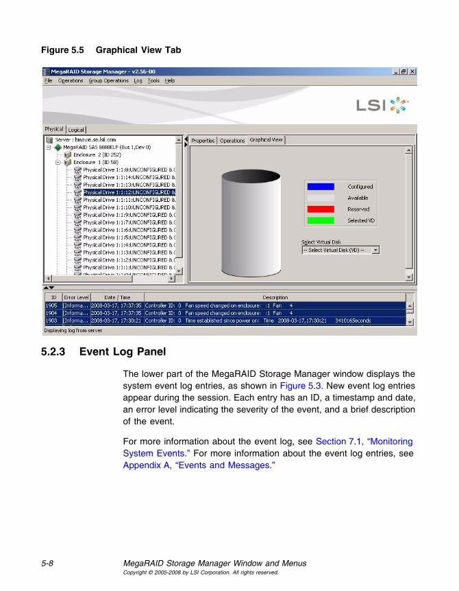
5-8 MegaRAID Storage Manager Window and MenusCopyright © 2005-2008 by LSI Corporation. All rights reserved.
Figure 5.5 Graphical View Tab
5.2.3 Event Log Panel
The lower part of the MegaRAID Storage Manager window displays the system event log entries, as shown in Figure 5.3. New event log entries appear during the session. Each entry has an ID, a timestamp and date, an error level indicating the severity of the event, and a brief description of the event.
For more information about the event log, see Section 7.1, “Monitoring System Events.” For more information about the event log entries, see Appendix A, “Events and Messages.”

MegaRAID Storage Manager Window 5-9Copyright © 2005-2008 by LSI Corporation. All rights reserved.
5.2.4 Menu Bar
Here are brief descriptions of the main selections on the MegaRAID Storage Manager menu bar. Specific menu options are described in more detail in Chapters 6, 7, and 8 of this manual.
5.2.4.1 File Menu
The File menu has an Exit option for exiting from the MegaRAID Storage Manager software. It also has a Rescan option for updating the display in the MegaRAID Storage Manager window. (Rescan is seldom required; the display normally updates automatically.)
5.2.4.2 Operations Menu
The Operations menu is available when a controller, drive, or virtual drive is selected in the MegaRAID Storage Manager window. The Operations menu options vary depending on what type of device is selected in the left panel of the MegaRAID Storage Manager window. For example, the Scan for Foreign Config option is available only when a controller is selected. The options also vary depending on the current state of the selected device. For example, if you select an offline drive, the Make Drive Online option appears in the Operations menu.
You can also view the Operations selections on the main window on the Operations tab in the right panel. If an operation requires user inputs before it can be executed, it appears in the Operations tab but not in the Operations menu. A device-specific Operations menu pops up if you right-click a device icon in the left panel.
Configuration options are also available. This is where you access the Configuration Wizard and other configuration-related commands. To access the other configuration commands, select Operations-> Configuration.
5.2.4.3 Group Operations Menu
The Group Operations menu options include Check Consistency, Initialize, and Show Progress.

5-10 MegaRAID Storage Manager Window and MenusCopyright © 2005-2008 by LSI Corporation. All rights reserved.
5.2.4.4 Tools Menu
On the Tools menu you can select Configure->Monitor Configurator to access the Event Configuration Notification screen, which you can use to set the alert delivery rules, event severity levels, exceptions, and email settings. For more information, see Section 7.2, “Configuring Event Notifications.”
5.2.4.5 Log Menu
The Log menu includes options for saving and clearing the message log. For more information, see Appendix A, “Events and Messages.”
5.2.4.6 Help Menu
On the Help menu you can select Help->Help to view the MegaRAID Storage Manager online help file. You can select Help->About to view version information for the MegaRAID Storage Manager software.
Note: When you use the MegaRAID Storage Manager online help, you may see a warning message that Internet Explorer has restricted the file from showing active content. If this warning appears, click on the active content warning bar and enable the active content.
Note: If you are using the Linux operating system, you must install Firefox® or Mozilla® for the MegaRAID Storage Manager online help to display.

MegaRAID SAS Software User’s Guide 6-1Copyright © 2005-2008 by LSI Corporation. All rights reserved.
Chapter 6Configuration
You use MegaRAID Storage Manager software to create and modify storage configurations on LSI SAS controllers. These controllers support RAID 0, RAID 1, RAID 5, RAID 6, RAID 10, RAID 50, and RAID 60 storage configurations. To learn more about RAID and RAID levels, see Chapter 1, “Introduction to RAID.”
The Reconstruction Wizard allows you to easily change RAID levels or to expand or reduce the capacity of existing virtual drives.
Note: You cannot create or modify a storage configuration unless you are logged on to a server with administrator privileges.
This chapter explains how to use MegaRAID Storage Manager software to perform the following configuration tasks:
• Section 6.1, “Creating a New Storage Configuration”
• Section 6.2, “Adding Hot Spare Drives”
• Section 6.3, “Changing Adjustable Task Rates”
• Section 6.4, “Changing Virtual Drive Properties”
• Section 6.5, “Changing a Virtual Drive Configuration”
• Section 6.6, “Deleting a Virtual Drive”
• Section 6.7, “Saving a Storage Configuration to Drive”
• Section 6.8, “Clearing a Storage Configuration from a Controller”
• Section 6.9, “Adding a Saved Storage Configuration”
6.1 Creating a New Storage Configuration
You can use the MegaRAID Storage Manager Configuration Wizard to create new storage configurations on systems with LSI SAS controllers.

6-2 ConfigurationCopyright © 2005-2008 by LSI Corporation. All rights reserved.
To open the MegaRAID Storage Manager Configuration Wizard, select a controller in the left panel of the MegaRAID Storage Manager window and then select Operations->Configuration->Configuration Wizard.
Figure 6.1 shows the first Configuration Wizard screen.
Figure 6.1 First Configuration Wizard Screen
The menu lists three configuration modes:
• Auto Configuration automatically creates an optimal configuration from the available drives.
• Manual Configuration gives you the greatest level of control in creating a new virtual drive.
• Guided Configuration asks you a few simple questions about what kind of configuration you want and then automatically creates it from the available drives.
Note: To create a RAID 0, RAID 1, RAID 5, or RAID 6 configuration, you can use Auto, Guided, or Manual mode. To create a RAID 10, RAID 50, or RAID 60 configuration, you must use the Manual Configuration mode.

Creating a New Storage Configuration 6-3Copyright © 2005-2008 by LSI Corporation. All rights reserved.
The following subsections explain how to use the Configuration Wizard to create storage configurations:
• Section 6.1.1, “Understanding Virtual Drive Parameters”
• Section 6.1.2, “Using Auto Configuration”
• Section 6.1.3, “Using Guided Configuration”
• Section 6.1.4, “Using Manual Configuration: RAID 0”
• Section 6.1.5, “Using Manual Configuration: RAID 1”
• Section 6.1.6, “Using Manual Configuration: RAID 5”
• Section 6.1.7, “Using Manual Configuration: RAID 6”
• Section 6.1.8, “Using Manual Configuration: RAID 10”
• Section 6.1.9, “Using Manual Configuration: RAID 50”
• Section 6.1.10, “Using Manual Configuration: RAID 60”
6.1.1 Understanding Virtual Drive Parameters
This section describes the Virtual Disk Parameters that you can set when you use the Guided Configuration or Manual Configuration modes of the Configuration Wizard. You should change these parameters only if you have a specific reason for doing so. It is usually best to leave them at their default settings.
• Stripe Size: Stripe sizes of 8, 16, 32, 64, 128, 256, 512, and 1024 Kbytes are supported. For more information, see the striping Glossary entry. The default is 64 Kbytes.
• Read Policy: Specify the read policy for this virtual drive:
◊ Always read ahead: Read ahead capability allows the controller to read sequentially ahead of requested data and to store the additional data in cache memory, anticipating that the data will be needed soon. This speeds up reads for sequential data, but there is little improvement when accessing random data.
◊ No read ahead: Disables the read ahead capability. This is the default.
◊ Adaptive read ahead: When selected, the controller begins using read ahead if the two most recent drive accesses

6-4 ConfigurationCopyright © 2005-2008 by LSI Corporation. All rights reserved.
occurred in sequential sectors. If the read requests are random, the controller reverts to No read ahead.
• Write Policy: Specify the write policy for this virtual drive:
◊ Write back: In this mode the controller sends a data transfer completion signal to the host when the controller cache has received all of the data in a transaction. This is the default.
◊ Write through: In this mode the controller sends a data transfer completion signal to the host when the drive subsystem has received all of the data in a transaction.
Note: The Write Policy depends on the status of the battery backup unit (BBU). If the BBU is not present or is bad, then the Write Policy will be Write through.
• IO Policy: The IO policy applies to reads on a specific virtual drive. It does not affect the read ahead cache.
◊ Cached IO: In this mode, all reads are buffered in cache memory. This is the default.
◊ Direct IO: In this mode, reads are not buffered in cache memory. Data is transferred to the cache and the host concurrently. If the same data block is read again, it comes from cache memory.
Cached IO provides faster processing, and Direct IO ensures that the cache and the host contain the same data.
• Access Policy: Select the type of data access that is allowed for this virtual drive.
◊ Read/Write: Allow read/write access. This is the default.
◊ Read Only: Allow read-only access.
◊ Blocked: Do not allow access.
• Disk Cache Policy: Select a cache setting for this drive:
◊ Enable: Enable the disk cache. This is the default.
◊ Disable: Disable the disk cache.
◊ Unchanged: Leave the current disk cache policy unchanged.

Creating a New Storage Configuration 6-5Copyright © 2005-2008 by LSI Corporation. All rights reserved.
• Init State: Specify the background initialization status:
◊ No Initialization: The new configuration is not initialized and the existing data on the drives is not overwritten. This is the default.
◊ Fast Initialization: MegaRAID Storage Manager software quickly writes zeroes to the first and last 10-Mbyte regions of the new virtual drive and then completes the initialization in the background. This allows you to start writing data to the virtual drive immediately.
◊ Full Initialization: A complete initialization is done on the new configuration. You cannot write data to the new virtual drive until the initialization is complete. This may take a long time if the drives are large.
6.1.2 Using Auto Configuration
Auto Configuration is the quickest and simplest way to create a new storage configuration. When you select Auto Configuration mode on the first Configuration Wizard screen, the Configuration Wizard creates the best configuration possible using the available drives.
Figure 6.2 shows the Auto Configuration screen.

6-6 ConfigurationCopyright © 2005-2008 by LSI Corporation. All rights reserved.
Figure 6.2 Auto Configuration Screen
Follow these steps to create a new storage configuration in Auto Configuration mode:
1. Select a redundancy option from the drop-down menu at the bottom of the Auto Configuration window:
– No Redundancy: The new configuration will have no data redundancy (RAID 0). If a drive in the configuration fails, all data will be lost.
– With Redundancy: The new configuration will have data redundancy, either through parity data (RAID 5 and RAID 6) or mirrored data (RAID 1). If a drive fails, data is still protected.
2. Select an initialization option from the drop-down menu at the bottom of the window:
– No Initialization: The new configuration is not initialized, and the existing data on the drives is not overwritten.
– Fast Initialization: MegaRAID Storage Manager software quickly writes zeroes to the first and last 10 Mbyte regions of the new virtual drive and then completes the initialization in the
Creating a New Storage Configuration 6-7Copyright © 2005-2008 by LSI Corporation. All rights reserved.
background. This allows you to start writing data to the virtual drive immediately.
– Full Initialization: A complete initialization is done on the new configuration. You cannot write data to the new virtual drive until the initialization is complete. This may take a long time if the drives are large.
3. (Optional) Click Modify if you want to change to Manual Configuration mode so that you can modify the suggested Auto Configuration.
When you click Modify, the Virtual Disk Creation screen appears.
a. Select the new virtual drive, and click Reclaim.
A message warns that you are about to delete the virtual drive.
b. Click next to a drive group in the list to select the new drive group from the Arrays list, and then change the virtual drive parameters as needed.
4. Click Finish. The new storage configuration will be created and initialized (unless you selected No Initialization).
6.1.3 Using Guided Configuration
Guided Configuration provides an easy way to create a new storage configuration. Based on the information that is provided, the Configuration Wizard uses the available drives to create an optimal storage configuration.
Figure 6.3 shows the first screen that appears when you select Guided Configuration.

6-8 ConfigurationCopyright © 2005-2008 by LSI Corporation. All rights reserved.
Figure 6.3 First Guided Configuration Screen
Follow these steps to create a new storage configuration in Guided Configuration mode:
1. Select a redundancy option at the top of the Guided Configuration window:
– Redundancy Only: Create a configuration only if redundancy (RAID 1, RAID 5, or RAID 6) is possible.
– Redundancy when possible: Create a redundant configuration if possible. Otherwise, create a non-redundant configuration.
– No Redundancy: Create a non-redundant configuration.
2. Choose whether you want to use existing drive groups in the new virtual drive. The options are:
– Use Existing Arrays Only
– Do not Use Existing Arrays
– Use Existing and New Arrays
The first and third options are disabled if there are no available existing drive groups.

Creating a New Storage Configuration 6-9Copyright © 2005-2008 by LSI Corporation. All rights reserved.
3. Select a maximum number of virtual drives to be created. The Configuration Wizard might not be able to create as many virtual drives as you want, depending on the current configuration and the number of virtual drives that have already been created.
4. Click Next to continue to the next window, as shown in Figure 6.4.
Figure 6.4 Second Guided Configuration Screen
5. Change the default virtual drive parameters in this window, if needed.
In the top section of the window you can specify the number of virtual drives to create. You can also choose to use less than the full capacity of this drive group for the virtual drive(s). (You could do this to leave capacity available for other virtual drives that you create later.) To learn about the Stripe Size and other virtual drive parameters, see Section 6.1.1, “Understanding Virtual Drive Parameters,” page 6-3.
6. Click Next to continue to the next window.
The VD Summary screen appears.

6-10 ConfigurationCopyright © 2005-2008 by LSI Corporation. All rights reserved.
7. Check the configuration that you have just defined. If it is acceptable, click Finish. If you want to change something, click Back to return to the previous windows.
6.1.4 Using Manual Configuration: RAID 0
Follow these steps to create a RAID 0 storage configuration using the Manual Configuration mode of the Configuration Wizard.
Figure 6.5 shows the first screen that appears when you select Manual Configuration.
Figure 6.5 First Manual Configuration Screen
1. In the first Manual Configuration window, select two or more available drives in the left panel and move them to the right panel.
To select non-consecutive drives in the list, click on a drive. Then click the Add (right arrow) button to move the selected drive to the right panel. Do this for each drive you want to add to the drive group.
To select two or more consecutive drives in the list, hold the SHIFT key down and click on the drives. Then click the Add (right arrow) button to move the selected drives to the right panel.

Creating a New Storage Configuration 6-11Copyright © 2005-2008 by LSI Corporation. All rights reserved.
Note: MegaRAID Storage Manager software does not allow you to select the drive on which the operating system is installed or any other drives that are already part of a configuration.
2. Click Accept to accept these drives for the new RAID 0 drive group.
Note: To remove a single drive from a proposed new drive group, select the drive icon in the right panel and click the Left Arrow button.
3. Click Next.
The next Configuration Wizard window appears, as shown in Figure 6.6.
Figure 6.6 Manual Configuration – Defining a Virtual Drive
The Arrays menu lists the new drive group that you just defined, plus any existing drive groups with holes (free space) that could be used for a new configuration.
4. From the Arrays menu, select the drive group to use for the new virtual drive.
5. In the right panel, select RAID 0 as the RAID level.

6-12 ConfigurationCopyright © 2005-2008 by LSI Corporation. All rights reserved.
6. (Optional) Set Size (in MB) to a lower number if you do not want to use the entire available capacity for the new virtual drive.
7. (Optional) Change the other Virtual Disk Properties, if necessary. For more information, see Section 6.1.1, “Understanding Virtual Drive Parameters.”
8. Click Accept to accept the configuration of the new virtual drive.
Note: Click the Reclaim button if you want to undo a virtual drive that you just defined. (For more information, see the reclaim virtual drive entry in the Glossary.)
9. Click Next to continue with the next configuration step.
The Virtual Disk Summary window appears.
10. Review the configuration shown in the Virtual Disk Summary window. If you want to change something, click Back and change the configuration parameters.
11. Click Finish to accept the configuration and start the initialization process (unless you selected No Initialization earlier).
6.1.5 Using Manual Configuration: RAID 1
Follow these steps to create a RAID 1 storage configuration using the Manual Configuration mode of the Configuration Wizard:
1. In the first Manual Configuration window, shown in Figure 6.5, select two available drives in the left panel.
To select non-consecutive drives in the list, click on a drive. Then click the Add (right arrow) button to move the selected drive to the right panel. Do this for each drive you want to add to the drive group.
To select two or more consecutive drives in the list, hold the SHIFT key down and click on the drives. Then click the Add (right arrow) button to move the selected drives to the right panel.
Note: MegaRAID Storage Manager software does not allow you to select the drive on which the operating system is installed or any other drives that are already part of a configuration.
2. Click Accept to accept these drives for the new RAID 1 drive group.

Creating a New Storage Configuration 6-13Copyright © 2005-2008 by LSI Corporation. All rights reserved.
3. If you want additional drives in the RAID 1 virtual drive, select two more drives for another RAID 1 drive group, click the Add button, and click Accept.
Note: A RAID 1 virtual drive can contain up to 16 drive groups and up to 32 drives in a single span. (Other factors, such as the type of controller, can limit the number of drives.) You must use two drives in each RAID 1 drive group in the span, and an even number of drives in the span.
4. Repeat step 3 until you have made all of the drive groups that you want.
5. Click Next.
The next Configuration Wizard window appears, as shown in Figure 6.6.
The Arrays menu lists the new drive group(s) that you just defined, plus any existing drive groups with holes (free space) that could be used for a new configuration.
6. Select the drive group(s) to use for the new virtual drive.
7. In the right panel, select RAID 1 as the RAID level.
8. (Optional) Set Size (in MB) to a lower number if you do not want to use the entire available capacity for the new virtual drive.
9. (Optional) Change the other Virtual Disk Properties, if necessary. For more information, see Section 6.1.1, “Understanding Virtual Drive Parameters.”
10. Click Accept to accept the configuration of the new virtual drive.
Note: Click the Reclaim button if you want to undo a virtual drive that you just defined. (For more information, see the reclaim virtual drive entry in the Glossary.)
11. Click Next to continue with the next configuration step.
The Virtual Disk Summary window appears.
12. Review the configuration shown in the window. If you want to change something, click Back and change the configuration parameters.
13. Click Finish to accept the configuration and start the initialization process (unless you selected No Initialization earlier).

6-14 ConfigurationCopyright © 2005-2008 by LSI Corporation. All rights reserved.
6.1.6 Using Manual Configuration: RAID 5
Follow these steps to create a RAID 5 configuration using the Manual Configuration mode of the Configuration Wizard:
1. In the first Manual Configuration window, shown in Figure 6.5, select three or more available drives in the left panel.
To select non-consecutive drives in the list, click on a drive. Then click the Add (right arrow) button to move the selected drive to the right panel. Do this for each drive you want to add to the drive group.
To select three or more consecutive drives in the list, hold the SHIFT key down and click on the drives. Then click the Add (right arrow) button to move the selected drives to the right panel.
Note: MegaRAID Storage Manager software does not allow you to select the drive on which the operating system is installed or any other drives that are already part of a configuration.
2. Click Accept to accept these drives for the new RAID 5 drive group.
3. Click Next.
The next Configuration Wizard window appears, as shown in Figure 6.6.
The Arrays menu lists the new drive group(s) that you just defined, plus any existing drive groups with holes (free space) that could be used for a new configuration.
4. Select the drive group to use for the new virtual drive.
5. In the right panel, select RAID 5 as the RAID level.
6. (Optional) Set Size (in MB) to a lower number if you do not want to use the entire available capacity for the new virtual drive.
7. (Optional) Change the other Virtual Disk Properties, if necessary. For more information, see Section 6.1.1, “Understanding Virtual Drive Parameters.”
8. Click Accept to accept the configuration of the new virtual drive.
Note: Click the Reclaim button if you want to undo a virtual drive that you just defined. (For more information, see the reclaim virtual drive in the Glossary.)

Creating a New Storage Configuration 6-15Copyright © 2005-2008 by LSI Corporation. All rights reserved.
9. Click Next to continue with the next configuration step.
The Virtual Disk Summary window appears.
10. Review the configuration shown in the window. If you want to change something, click Back and change the configuration parameters.
11. Click Finish to accept the configuration and start the initialization process (unless you selected No Initialization earlier).
6.1.7 Using Manual Configuration: RAID 6
Follow these steps to create a RAID 6 configuration using the Manual Configuration mode of the Configuration Wizard:
1. In the first Manual Configuration window, shown in Figure 6.5, select three or more available drives in the left panel.
To select non-consecutive drives in the list, click on a drive. Then click the Add (right arrow) button to move the selected drive to the right panel. Do this for each drive you want to add to the drive group.
To select three or more consecutive drives in the list, hold the SHIFT key down and click on the drives. Then click the Add (right arrow) button to move the selected drives to the right panel.
Note: MegaRAID Storage Manager software does not allow you to select the drive on which the operating system is installed or any other drives that are already part of a configuration.
2. Click Accept to accept these drives for the new RAID 6 drive group.
3. Click Next.
The next Configuration Wizard window appears, as shown in Figure 6.6.
The Arrays menu lists the new drive group(s) that you just defined, plus any existing drive groups with holes (free space) that could be used for a new configuration.
4. Select the drive group to use for the new virtual drive.
5. In the right panel, select RAID 6 as the RAID level.
6. (Optional) Set Size (in MB) to a lower number if you do not want to use the entire available capacity for the new virtual drive.
6-16 ConfigurationCopyright © 2005-2008 by LSI Corporation. All rights reserved.
7. (Optional) Change the other Virtual Disk Properties, if necessary. For more information, see Section 6.1.1, “Understanding Virtual Drive Parameters.”
8. Click Accept to accept the configuration of the new virtual drive.
Note: Click the Reclaim button if you want to undo a virtual drive that you just defined. (For more information, see the reclaim virtual drive entry in the Glossary.)
9. Click Next to continue with the next configuration step.
The Virtual Disk Summary window appears.
10. Review the configuration shown in the window. If you want to change something, click Back and change the configuration parameters.
11. Click Finish to accept the configuration and start the initialization process (unless you selected No Initialization earlier).
6.1.8 Using Manual Configuration: RAID 10
Follow these steps to create a RAID 10 storage configuration using the Manual Configuration mode of the Configuration Wizard:
1. In the first Manual Configuration window, shown in Figure 6.5, select two available drives in the left panel.
To select non-consecutive drives in the list, click on a drive. Then click the Add (right arrow) button to move the selected drive to the right panel. Do this for each drive you want to add to the drive group.
To select two or more consecutive drives in the list, hold the SHIFT key down and click on the drives. Then click the Add (right arrow) button to move the selected drives to the right panel.
2. Click Accept to accept the drives for a new RAID 1 drive group.
3. Select two more drives for a second RAID 1 drive group, and click Accept.
4. If you want additional drives in the RAID 10 virtual drive, select two more drives for another RAID 1 drive group, click the Add button, and click Accept.
Note: RAID 10 supports a maximum of eight spans, with up to 32 drives per span. (Other factors, such as the type of controller, can limit the number of drives.) You must use an

Creating a New Storage Configuration 6-17Copyright © 2005-2008 by LSI Corporation. All rights reserved.
even number of drives in each RAID 1 drive group in the span. You can have an even or odd number of spans.
5. Repeat step 3 until you have made all of the drive groups that you want.
6. Click Next.
The next Configuration Wizard window appears, as shown in Figure 6.6.
The Arrays menu lists the new drive groups that you just defined, plus any existing drive groups with holes (free space) that could be used for a new configuration.
7. In the left panel, select the two RAID 1 drive groups from the menu.
8. In the right panel, select RAID 10 as the RAID level.
9. (Optional) Set Size (in MB) to a lower number if you do not want to use the entire available capacity for the new virtual drive.
10. (Optional) Change the other Virtual Disk Properties, if necessary. For more information, see Section 6.1.1, “Understanding Virtual Drive Parameters.”
11. Click Accept to accept the configuration of the new virtual drive.
Note: Click the Reclaim button if you want to undo a virtual drive that you just defined. (For more information, see the reclaim virtual drive entry in the Glossary.)
12. Click Next to continue with the next configuration step.
The Virtual Disk Summary window appears.
13. Review the configuration shown in the window. If you want to change something, click Back and change the configuration parameters.
14. Click Finish to accept the configuration and start the initialization process (unless you selected No Initialization earlier).
6.1.9 Using Manual Configuration: RAID 50
Follow these steps to create a RAID 50 storage configuration using the Manual Configuration mode of the Configuration Wizard:
6-18 ConfigurationCopyright © 2005-2008 by LSI Corporation. All rights reserved.
1. In the first Manual Configuration window, shown in Figure 6.5, select three or more available drives in the left panel. Click the Right Arrow button to move the selected drives to the right panel.
2. Click Accept to accept these drives for a new RAID 5 drive group.
3. Select more drives for a second RAID 5 drive group, and click Accept.
4. Click Next.
The next Configuration Wizard window appears, as shown in Figure 6.6.
The Arrays menu lists the new drive groups that you just defined, plus any existing drive groups with holes (free space) that could be used for a new configuration.
5. In the left panel, select the two RAID 5 drive groups from the menu.
6. In the right panel, select RAID 50 as the RAID level.
7. (Optional) Set Size (in MB) to a lower number if you do not want to use the entire available capacity for the new virtual drive.
8. (Optional) Change the other Virtual Disk Properties, if necessary. For more information, see Section 6.1.1, “Understanding Virtual Drive Parameters.”
9. Click Accept to accept the configuration of the new virtual drive.
Note: Click the Reclaim button if you want to undo a virtual drive that you just defined. (For more information, see the reclaim virtual drive entry in the Glossary.)
10. Click Next to continue with the next configuration step.
The Virtual Disk Summary window appears.
11. Review the configuration shown in the window. If you want to change something, click Back and change the configuration parameters.
12. Click Finish to accept the configuration and start the initialization process (unless you selected No Initialization earlier).
6.1.10 Using Manual Configuration: RAID 60
Follow these steps to create a RAID 60 storage configuration using the Manual Configuration mode of the Configuration Wizard:

Creating a New Storage Configuration 6-19Copyright © 2005-2008 by LSI Corporation. All rights reserved.
1. In the first Manual Configuration window, shown in Figure 6.5, select three or more available drives in the left panel. Click the Right Arrow button to move the selected drives to the right panel.
2. Click Accept to accept these drives for a new RAID 6 drive group.
3. Select more drives for a second RAID 6 drive group, and click Accept.
4. Click Next.
The next Configuration Wizard window appears, as shown in Figure 6.6.
The Arrays menu lists the new drive groups that you just defined, plus any existing drive groups with holes (free space) that could be used for a new configuration.
5. In the left panel, select the two RAID 6 drive groups from the menu.
6. In the right panel, select RAID 60 as the RAID level.
7. (Optional) Set Size (in MB) to a lower number if you do not want to use the entire available capacity for the new virtual drive.
8. (Optional) Change the other Virtual Disk Properties, if necessary. For more information, see Section 6.1.1, “Understanding Virtual Drive Parameters.”
9. Click Accept to accept the configuration of the new virtual drive.
Note: Click the Reclaim button if you want to undo a virtual drive that you just defined. (For more information, see the reclaim virtual drive entry in the Glossary.)
10. Click Next to continue with the next configuration step.
The Virtual Disk Summary window appears.
11. Review the configuration shown in the window. If you want to change something, click Back and change the configuration parameters.
12. Click Finish to accept the configuration and start the initialization process (unless you selected No Initialization earlier).

6-20 ConfigurationCopyright © 2005-2008 by LSI Corporation. All rights reserved.
6.2 Adding Hot Spare Drives
Hot spares are drives that are available to automatically replace failed drives in a RAID 1, RAID 5, RAID 6, RAID 10, RAID 50, or RAID 60 virtual drive. Global hot spares are available to any virtual drive on a specific controller.
To add a global hot spare drive, follow these steps:
1. Select the Physical View tab in the left panel of the MegaRAID Storage Manager window, and select the icon of an unused drive.
For each drive, the left panel displays the port number, enclosure number, slot number, drive state, drive capacity, and drive manufacturer.
2. In the right panel of the MegaRAID Storage Manager window, select the Operations tab.
3. Select Make Global Hotspare, as shown in Figure 6.7.
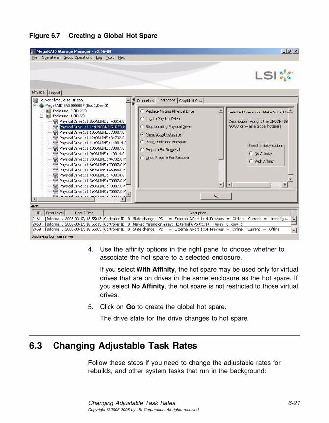
Changing Adjustable Task Rates 6-21Copyright © 2005-2008 by LSI Corporation. All rights reserved.
Figure 6.7 Creating a Global Hot Spare
4. Use the affinity options in the right panel to choose whether to associate the hot spare to a selected enclosure.
If you select With Affinity, the hot spare may be used only for virtual drives that are on drives in the same enclosure as the hot spare. If you select No Affinity, the hot spare is not restricted to those virtual drives.
5. Click on Go to create the global hot spare.
The drive state for the drive changes to hot spare.
6.3 Changing Adjustable Task Rates
Follow these steps if you need to change the adjustable rates for rebuilds, and other system tasks that run in the background:

6-22 ConfigurationCopyright © 2005-2008 by LSI Corporation. All rights reserved.
Note: LSI recommends that you leave the adjustable task rates at their default settings to achieve the best system performance. If you raise the task rates above the defaults, foreground tasks will run more slowly and it may seem that the system is not responding. If you lower the task rates below the defaults, rebuilds and other background tasks may run very slowly and may not complete within a reasonable time. If you decide to change the values, record the original default value here so you can restore them later, if necessary:Rebuild Rate: ____________Background Initialization (BGI) Rate: ____________Check Consistency Rate: ____________
1. Select the Physical View tab in the left panel of the MegaRAID Storage Manager window, and select a controller icon.
2. In the right panel of the MegaRAID Storage Manager window, select the Operations tab, and select Set Adjustable Task Rates.
The default task rates appear in the right panel, as shown in Figure 6.8.
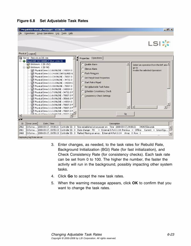
Changing Adjustable Task Rates 6-23Copyright © 2005-2008 by LSI Corporation. All rights reserved.
Figure 6.8 Set Adjustable Task Rates
3. Enter changes, as needed, to the task rates for Rebuild Rate, Background Initialization (BGI) Rate (for fast initialization), and Check Consistency Rate (for consistency checks). Each task rate can be set from 0 to 100. The higher the number, the faster the activity will run in the background, possibly impacting other system tasks.
4. Click Go to accept the new task rates.
5. When the warning message appears, click OK to confirm that you want to change the task rates.

6-24 ConfigurationCopyright © 2005-2008 by LSI Corporation. All rights reserved.
6.4 Changing Virtual Drive Properties
You can change a virtual drive’s Read Policy, Write Policy, and other properties at any time after the virtual drive is created. To do this, follow these steps:
1. Click the Logical view tab in the left panel of the MegaRAID Storage Manager window.
2. Select a virtual drive icon in the left panel of the MegaRAID Storage Manager window.
3. In the right panel, select the Operations tab, and then select Set Virtual Disk Properties.
A list of Virtual Disk Properties appears in the right panel, as shown in Figure 6.9.
Figure 6.9 Set Virtual Disk Properties

Changing a Virtual Drive Configuration 6-25Copyright © 2005-2008 by LSI Corporation. All rights reserved.
4. Change the virtual drive properties as needed in the right panel. For information on these properties, see Section 6.1.1, “Understanding Virtual Drive Parameters,” page 6-3.
5. Click Go to accept the changes.
6.5 Changing a Virtual Drive Configuration
You can use the MegaRAID Storage Manager Reconstruction Wizard to change the configuration of a virtual drive.
Caution: Be sure to back up the data on the virtual drive before you change its configuration.
The Reconstruction Wizard allows you to change a virtual drive configuration by adding drives to the virtual drive, removing drives from it, or changing its RAID level.
Note: You cannot change the configuration of a RAID 10, or RAID 50, or RAID 60 virtual drive. You cannot change a RAID 0, RAID 1, RAID 5, or RAID 6 configuration if two or more virtual drives are defined on a single drive group. (The Logical view tab shows which drive groups and drives are used by each virtual drive.)
Perform the following steps to access the Reconstruction Wizard options:
1. To start the Reconstruction Wizard, click on Logical view, and select a virtual drive icon in the left panel of the MegaRAID Storage Manager window.
2. Select Operations->Advanced Operations->Reconstruction Wizard from the menu. Another option is to right-click on the virtual drive icon to access the Reconstruction Wizard.
A warning to back up your data appears.
3. Select Confirm at the warning and click Yes.
The Reconstruction Wizard menu appears, as shown in Figure 6.10

6-26 ConfigurationCopyright © 2005-2008 by LSI Corporation. All rights reserved.
Figure 6.10 Reconstruction Wizard
This section has the following subsections explaining the Reconstruction Wizard options:
• Section 6.5.1, “Adding a Drive to a Configuration”
• Section 6.5.2, “Removing a Drive from a Configuration”
• Section 6.5.3, “Changing the RAID Level of a Configuration.”
6.5.1 Adding a Drive to a Configuration
Caution: Be sure to back up the data on the virtual drive before you add a drive to it.
Follow these steps to add a drive to a configuration with the Reconstruction Wizard:
1. Click Add Drive on the Reconstruction Wizard screen.
2. When the next screen appears, select an available drive in the top panel, and click the Down Arrow button to move it to the Selected Drive list.
3. Click Next to continue.
The next screen appears.
Changing a Virtual Drive Configuration 6-27Copyright © 2005-2008 by LSI Corporation. All rights reserved.
4. (Optional) Select a different RAID level for the configuration from the drop-down menu in the lower right of the window.
5. Review the information in the window. If everything is acceptable, click Finish.
A warning states that this operation cannot be aborted and asks whether you want to continue.
Note: If you add a drive to a RAID 1 configuration, the RAID level automatically changes to RAID 5.
A reconstruction operation begins on the virtual drive. You can monitor the progress of the reconstruction in the Group Show Progress window. To do this, select Group Operations->Show Progress.
6.5.2 Removing a Drive from a Configuration
Caution: Be sure to back up the data on the virtual drive before you remove a drive from it.
Follow these steps to remove a drive from a RAID 1, RAID 5, or RAID 6 configuration with the Reconstruction Wizard:
1. Click Remove Drive on the Configuration Wizard screen.
This option is not available for RAID 0 configurations.
2. When the next screen appears, select a drive in the top panel, and click the Down Arrow button to remove it from the configuration.
3. Click Next to continue.
The next screen appears.
4. (Optional) Select a different RAID level from the drop-down menu in the lower right of the window.
5. Review the information in the window. If everything is acceptable, click Finish.
A warning states that this operation cannot be aborted and asks whether you want to continue.
Note: If you remove a drive from a RAID 5 configuration, the RAID level automatically changes to RAID 0.

6-28 ConfigurationCopyright © 2005-2008 by LSI Corporation. All rights reserved.
A reconstruction operation begins on the virtual drive. You can monitor the progress of the reconstruction in the Group Show Progress window. To do this, select Group Operations->Show Progress.
6.5.3 Changing the RAID Level of a Configuration
Caution: Be sure to back up the data on the virtual drive before you change its RAID level.
Follow these steps to change the RAID level of a RAID 1 or RAID 5 configuration with the Configuration Wizard:
1. Click Change RAID Level on the Configuration Wizard screen.
This option is not available for RAID 0 configurations.
2. When the next screen appears, select a RAID level from the drop-down menu in the lower right corner.
3. Review the information in the window. If everything is acceptable, click Finish.
A warning states that this operation cannot be aborted and asks whether you want to continue.
A reconstruction operation begins on the virtual drive. You can monitor the progress of the reconstruction in the Group Show Progress window. To do this, select Group Operations->Show Progress.
6.6 Deleting a Virtual Drive
Caution: Be sure to back up the data on the virtual drive before you delete it. Be sure that the operating system is not installed on this virtual drive.
You can delete virtual drives to rearrange the storage space. To delete a virtual drive, follow these steps:
1. Back up all user data on the virtual drive you intend to delete.
2. In the left panel of the MegaRAID Storage Manager window, select the Logical tab, and click the icon of the virtual drive you want to delete.

Saving a Storage Configuration to Drive 6-29Copyright © 2005-2008 by LSI Corporation. All rights reserved.
3. In the right panel, select the Operations tab, and select Delete Virtual Disk.
4. Click Go.
5. When the warning messages appear, click Yes to confirm that you want to delete the virtual drive.
6.7 Saving a Storage Configuration to Drive
You can save an existing controller configuration to a file so you can apply it to another controller. To save a configuration file, follow these steps:
1. Select a controller icon in the left panel of the MegaRAID Storage Manager window.
2. On the menu bar, select Operations->Configuration->Save Configuration.
The Save dialog box appears.
3. In the Save dialog box, type a name for the configuration file, or accept the default name (hostname.cfg).
4. Click Save to save the configuration file.
6.8 Clearing a Storage Configuration from a Controller
You must clear a storage configuration from a controller before you can create a new configuration on the controller or load a previously saved configuration file.
Caution: Before you clear a configuration, be sure to save any data that you want to keep. Clearing a configuration deletes all data from the drives of the existing configuration. Be sure that the operating system is not installed on this configuration.
To clear a configuration from a controller, follow these steps:
1. Select a controller icon in the left panel of the MegaRAID Storage Manager window.

6-30 ConfigurationCopyright © 2005-2008 by LSI Corporation. All rights reserved.
2. On the menu bar, select Operations->Configuration->Clear Configuration.
A warning message appears that states that clearing the configuration will destroy the virtual drives and result in data loss on the selected controller.
3. Click Yes to clear the configuration or No to cancel the operation.
6.9 Adding a Saved Storage Configuration
When you replace a controller, or when you want to duplicate an existing storage configuration on a new controller, you can add a saved configuration to the controller.
Caution: When you add a saved configuration to a replacement controller, be sure that the number and capacity of the drives connected to the controller are exactly the same as when the configuration was saved.
To add a saved configuration, follow these steps:
1. Select a controller icon in the left panel of the MegaRAID Storage Manager window.
2. On the menu bar, select Operations->Configuration->Add Configuration.
A warning message appears that states that this operation may cause an unstable condition because of differences in the two configurations.
3. Click Yes.
4. When the Open dialog box appears, select the configuration file, and click Open.
5. View the configuration detail, then select Apply.
6. Confirm the new configuration when prompted.

MegaRAID SAS Software User’s Guide 7-1Copyright © 2005-2008 by LSI Corporation. All rights reserved.
Chapter 7Monitoring System Events and Storage Devices
The MegaRAID Storage Manager software enables you to monitor the status of drives, virtual drives, and other storage devices. This chapter explains how to use MegaRAID Storage Manager software to perform the following monitoring tasks:
• Section 7.1, “Monitoring System Events”
• Section 7.2, “Configuring Event Notifications”
• Section 7.3, “Monitoring Controllers”
• Section 7.4, “Monitoring Drives”
• Section 7.5, “Running a Patrol Read”
• Section 7.6, “Monitoring Virtual Drives”
• Section 7.7, “Monitoring Enclosures”
• Section 7.8, “Monitoring Battery Backup Units”
• Section 7.9, “Monitoring Rebuilds and Other Processes”
7.1 Monitoring System Events
MegaRAID Storage Manager software monitors the activity and performance of all controllers in the system and the storage devices connected to them. When an event occurs (such as the creation of a new virtual drive or the removal of a drive) an event message appears in the log displayed at the bottom of the MegaRAID Storage Manager window, as shown in Figure 7.1.
You can use MegaRAID Storage Manager to alert you about events. There are settings are for the delivery of alerts, the severity level of events, exceptions, and email settings.

7-2 Monitoring System Events and Storage DevicesCopyright © 2005-2008 by LSI Corporation. All rights reserved.
Figure 7.1 Event Information Window
Each message that appears in the event log has a severity level that indicates the importance of the event, as shown in Table 7.1, a date and timestamp, and a brief description. You can click on an event to display the same information in a window. (For a list of all events, see Section Appendix A, “Events and Messages.”)
Table 7.1 Event Severity Levels
Severity Level Meaning
Information Informational message. No user action is necessary.
Warning Some component might be close to a failure point.
Critical A component has failed, but the system has not lost data.
Fatal A component has failed, and data loss has occurred or will occur.

Configuring Event Notifications 7-3Copyright © 2005-2008 by LSI Corporation. All rights reserved.
The Log menu has four options:
• Save Log: Saves the current log to a .log file.
• Save Log Text: Saves the current log in .txt format.
• View Saved Log: Clears the current log information. You have the option of saving the log first.
• Clear Log: Enables you to load a local .log file.
7.2 Configuring Event Notifications
The Event Notification Configuration utility allows you to control and configure the notifications that MegaRAID Storage Manager software sends when various system events occur. You can use the Event Notification Configuration screen to perform the following functions:
• Set rules for the delivery of alerts
• Change the severity level of events
• Define selected events as exceptions
• Select the settings for the email addresses that are recipients of alert notifications
To access this screen, select Tools->Configure->Monitor Configurator. The Event Notification Configuration screen appears, as shown in Figure 7.2.
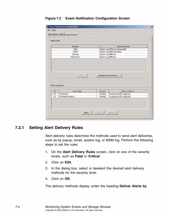
7-4 Monitoring System Events and Storage DevicesCopyright © 2005-2008 by LSI Corporation. All rights reserved.
Figure 7.2 Event Notification Configuration Screen
7.2.1 Setting Alert Delivery Rules
Alert delivery rules determine the methods used to send alert deliveries, such as by popup, email, system log, or MSM log. Perform the following steps to set the rules:
1. On the Alert Delivery Rules screen, click on one of the severity levels, such as Fatal or Critical.
2. Click on Edit.
3. In the dialog box, select or deselect the desired alert delivery methods for the severity level.
4. Click on OK.
The delivery methods display under the heading Deliver Alerts by.

Configuring Event Notifications 7-5Copyright © 2005-2008 by LSI Corporation. All rights reserved.
7.2.2 Changing the Event Severity
To change the severity level for a specific event, perform the following steps (see Table 7.1 for details about the severity levels):
1. On the Alert Delivery Rules screen, click on Change Events Severity.
The Change Events Severity dialog box appears, as shown in Figure 7.3. The dialog box displays the events by their ID number, description, and severity level.
Figure 7.3 Change Events Severity
2. Click on an event in the list to select it.
To select multiple events at one time, hold the <Shift> key while you click on two events. This selects those two events and any events in-between.

7-6 Monitoring System Events and Storage DevicesCopyright © 2005-2008 by LSI Corporation. All rights reserved.
To select multiple events one at a time, hold the <Ctrl> key while you click on separate events.
3. Click the box under the Severity heading to display the list of severity levels.
4. Select a different severity level for the event from the list.
5. Click Apply.
The severity level for the event changes in the dialog box.
6. Click OK.
The severity level for the event changes and the dialog box closes.
7.2.3 Defining Exceptions
You can select events to make as exceptions to the alert delivery rules, and then edit or remove these exceptions. A reason for making exceptions is to change the alert delivery options for the event without changing the severity level. To add, edit, or remove exceptions, perform the following steps:
1. Click on the Alert Delivery Rules tab.
2. Click on the Add button in the Define exceptions section of the screen.
The dialog box used to add events to the exceptions list appears, as shown in Figure 7.4.

Configuring Event Notifications 7-7Copyright © 2005-2008 by LSI Corporation. All rights reserved.
Figure 7.4 Add an Event to the Exceptions List
3. Click on an event to select it and click OK.
The event displays in the Define exceptions section of the Event Notification Configuration screen.
4. To edit the exception event, click on the event, and click on Edit.
A dialog box appears, as shown in Figure 7.5.

7-8 Monitoring System Events and Storage DevicesCopyright © 2005-2008 by LSI Corporation. All rights reserved.
Figure 7.5 Edit Delivery Methods for Exception Events
5. Select the desired alert delivery methods and click on OK.
The alert delivery methods for the exception event are changed.
6. To remove the event as an exception, click on the exception event in the Event Notification Configuration screen, and then click Remove.
The event is no longer in the list of exceptions.
7.2.4 Selecting Email Settings
You can use the Event Notification Configuration screen to enter email addresses of recipients of the alert notifications. MegaRAID Storage Manager sends alert notifications to the email addresses listed in the Recipients section of this screen. This screen displays the sender address, the SMTP server number, and the email addresses for alert notification recipients.
You can add, edit, or remove email addresses, and perform a test to make sure the recipient receives a alert notification. To select email settings, perform the following steps:
1. Click on the E-mail Settings tab on the Event Notification Configuration screen.
The E-mail Settings screen appears, as shown in Figure 7.6.

Configuring Event Notifications 7-9Copyright © 2005-2008 by LSI Corporation. All rights reserved.
Figure 7.6 Email Settings
2. Click on the Add button to add an email address.
The following dialog box appears, as shown in Figure 7.7.
Figure 7.7 Add Email Address Dialog Box
3. Enter the email address you want to add and click on OK.
The added email address appears in the Recipients section of the E-mail Settings screen.
4. Click on File and select Save As to save the email address.

7-10 Monitoring System Events and Storage DevicesCopyright © 2005-2008 by LSI Corporation. All rights reserved.
5. To edit an email address, click on the email address in the Recipients section of the screen, click on Edit, and then change the email address.
6. To remove an email address, click on the email address in the Recipients section of the screen, and then click on Remove.
7. To send a test message to an alert recipient, click on an email address in the Recipients section of the screen, and then click Test.
If MegaRAID Storage Manager cannot send an email message to the email address, an error message appears.
7.3 Monitoring Controllers
When MegaRAID Storage Manager software is running, you can see the status of all controllers in the left panel of the MegaRAID Storage Manager window. If the controller is operating normally, the controller
icon looks like this: . If the controller has failed, a small red circle appears to the right of the icon. (See Section 5.2.1, “Physical/Logical View Panel” for a complete list of device icons.)
To display complete controller information, click a controller icon in the left panel of the MegaRAID Storage Manager window, and click the Properties tab in the right panel.
Figure 7.8 shows the Controller Information window.

Monitoring Controllers 7-11Copyright © 2005-2008 by LSI Corporation. All rights reserved.
Figure 7.8 Controller Information
Most of the information on this screen is self-explanatory. Note the following:
• The Rebuild Rate, Patrol Read Rate, Reconstruction Rate, Consistency Check Rate, and BGI Rate (background initialization) are all user selectable. For more information, see Section 6.3, “Changing Adjustable Task Rates,” page 6-21.
• The BBU Present field indicates whether a battery backup unit is installed.
• The Alarm Present and Alarm Enabled fields indicate whether the controller has an alarm to alert the user with an audible tone when there is an error or problem on the controller. There are options on the controller Properties tab for silencing or disabling the alarm. All

7-12 Monitoring System Events and Storage DevicesCopyright © 2005-2008 by LSI Corporation. All rights reserved.
controller properties are defined in the Section Appendix B, “Glossary.”
7.4 Monitoring Drives
When MegaRAID Storage Manager software is running, you can see the status of all drives in the left panel of the MegaRAID Storage Manager
window. If the drive is operating normally, its icon looks like this: . If the drive has failed, a small red circle appears to the right of the icon, like this: . (See Section 5.2.1, “Physical/Logical View Panel” for a complete list of device icons.)
To display complete drive information, click a drive icon in the left panel of the MegaRAID Storage Manager window, and click the Properties tab in the right panel.
Figure 7.9 shows the Properties panel for a drive.
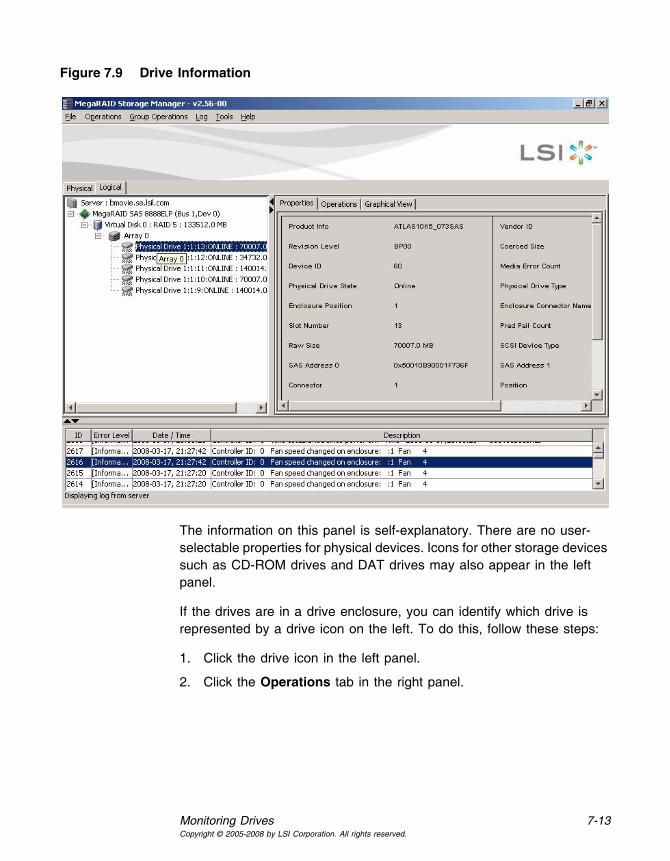
Monitoring Drives 7-13Copyright © 2005-2008 by LSI Corporation. All rights reserved.
Figure 7.9 Drive Information
The information on this panel is self-explanatory. There are no user-selectable properties for physical devices. Icons for other storage devices such as CD-ROM drives and DAT drives may also appear in the left panel.
If the drives are in a drive enclosure, you can identify which drive is represented by a drive icon on the left. To do this, follow these steps:
1. Click the drive icon in the left panel.
2. Click the Operations tab in the right panel.

7-14 Monitoring System Events and Storage DevicesCopyright © 2005-2008 by LSI Corporation. All rights reserved.
3. Select Locate Physical Drive, and click Go.
The LED on the drive in the enclosure starts blinking to show its location.
Note: LEDs on drives that are global hotspares do not blink.
4. To stop the drive light from blinking, select Stop Locating Physical Drive, and click Go.
All of the drive properties are defined in the Glossary.
To display a graphical view of a drive, click on a drive icon in the left panel of the MegaRAID Storage Manager window, and click the Graphical View tab. In Graphical View, the drive’s storage capacity is color coded according to the legend shown on the screen: configured space is blue, available space is white, and reserved space is red. When you select a virtual drive from the drop-down menu, the drive space used by that virtual drive is displayed in green.
7.5 Running a Patrol Read
A patrol read periodically verifies all sectors of drives connected to a controller, including the system reserved area in the RAID configured drives. A patrol read can be used for all RAID levels and for all hot spare drives. A patrol read is initiated only when the controller is idle for a defined time period and has no other background activities. To start a patrol read, follow these steps:
1. Click a controller icon in the left panel of the MegaRAID Storage Manager window.
2. Select Operations->Start Patrol Read.
To change the patrol read settings, follow these steps:
1. Click a controller icon in the left panel of the MegaRAID Storage Manager window.
2. Select the Operations tab in the right panel, and select Set Patrol Read Properties, as shown in Figure 7.10.

Running a Patrol Read 7-15Copyright © 2005-2008 by LSI Corporation. All rights reserved.
Figure 7.10 Patrol Read Configuration
3. Select an Operation Mode for a patrol read. The options are:
– Auto: Patrol read runs automatically at the time interval you specify on this screen.
– Manual: Patrol read runs only when you manually start it by selecting Start Patrol Read from the controller Options panel.
– Disabled: Patrol read does not run.
4. (Optional) Specify a maximum count of drives to include in the patrol read. The count must be between 0 and 255.
5. (Optional) Select virtual drives on this controller to exclude from the patrol read. The existing virtual drives are listed in the gray box. To exclude a virtual drive, check the box next to it.

7-16 Monitoring System Events and Storage DevicesCopyright © 2005-2008 by LSI Corporation. All rights reserved.
6. (Optional) Change the frequency at which the patrol read will run. The default frequency is 7 days (168 hours), which is suitable for most configurations. (You can select second, minute, or hour as the unit of measurement.)
Note: LSI recommends that you leave the patrol read frequency and other patrol read settings at the default values to achieve the best system performance. If you decide to change the values, record the original default value here so you can restore them later, if necessary:Patrol Read Frequency: ___________________Continuous Patrolling: Enabled/DisabledPatrol Read Task Rate: ___________________
7. (Optional) Select Continuous Patrolling if you want patrol read to run continuously in the background instead of running at periodic intervals. If you select Continuous Patrolling, the time interval field is grayed out.
8. Click Go to enable these patrol read options.
Note: Patrol read does not report on its progress while it is running. The patrol read status is reported in the event log only.
You can also (optionally) change the patrol read task rate. The task rate determines the amount of system resources that are dedicated to a patrol read when it is running. LSI recommends, however, that you leave the patrol read task rate at its default setting. If you raise the task rate above the default, foreground tasks will run more slowly and it may seem that the system is not responding. If you lower the task rate below the default, rebuilds and other background tasks may run very slowly and may not complete within a reasonable time. For more information, about the patrol read task rate, see Section 6.3, “Changing Adjustable Task Rates.”
7.6 Monitoring Virtual Drives
When MegaRAID Storage Manager software is running, you can see the status of all virtual drives. If a virtual drive is operating normally, the icon
looks like this: . If the virtual drive is running in Degraded mode (for

Monitoring Virtual Drives 7-17Copyright © 2005-2008 by LSI Corporation. All rights reserved.
example, if a drive has failed), a small yellow circle appears to the right
of the icon: . A red circle indicates that the virtual disk has failed and data has been lost.
When the Logical tab is selected, the left panel of the MegaRAID Storage Manager window shows which drives are used by each virtual drive. The same drive can be used by multiple virtual drives.
To display complete virtual drive information, click the Logical tab in the left panel, click on a virtual drive icon in the left panel, and click the Properties tab in the right panel. All virtual drive properties are defined in the Glossary. Figure 7.11 shows the Properties panel for a virtual drive.
Figure 7.11 Virtual Disk Properties
7-18 Monitoring System Events and Storage DevicesCopyright © 2005-2008 by LSI Corporation. All rights reserved.
The RAID level, stripe size, and access policy of the virtual drive are set when it is configured.
Note: You can change the read policy, write policy, and other virtual drive properties by selecting Operations->Set Virtual Disk Properties.
If the drives in the virtual drive are in an enclosure, you can identify them by making their LEDs blink. To do this, follow these steps:
1. Click the virtual drive icon in the left panel.
2. Click the Operations tab in the right panel.
3. Select Locate Virtual Disk, and click Go.
The LEDs on the drives in the virtual drive start blinking (except for hot spare drives).
4. To stop the LEDs from blinking, select Stop Locating Virtual Disk, and click Go.
To display a graphical view of a virtual drive, click on a virtual drive icon in the left panel of the MegaRAID Storage Manager window, and click the Graphical View tab. In Graphical View, the drive group used for this virtual drive is shaded blue to show how much of the drive group capacity is used by this virtual drive. If part of the drive group is shaded white, this indicates that some of the capacity is used by another virtual drive. In a RAID 10, RAID 50, or RAID 60 configuration, two drive groups are used by one virtual drive.
7.7 Monitoring Enclosures
When MegaRAID Storage Manager software is running, you can see the status of all enclosures connected to the server by selecting the Physical tab in the left panel. If an enclosure is operating normally, the
icon looks like this: . If the enclosure is not functioning normally—for example, if a fan has failed—a small yellow or red circle appears to the right of the icon.
Information about the enclosure appears in the right panel when you select the Properties tab. Figure 7.12 shows the more complete

Monitoring Battery Backup Units 7-19Copyright © 2005-2008 by LSI Corporation. All rights reserved.
enclosure information that is displayed when you select the Graphical View tab.
Figure 7.12 Enclosure Information – Graphical View
The display in the center of the screen shows how many slots of the enclosure are actually populated by drives, and the lights on the drives show the drive status. The information on the right shows you the status of the temperature sensors, fans, and power supplies in the enclosure.
7.8 Monitoring Battery Backup Units
When MegaRAID Storage Manager software is running, you can see the status of all BBUs connected to controllers in the server by selecting the

7-20 Monitoring System Events and Storage DevicesCopyright © 2005-2008 by LSI Corporation. All rights reserved.
Physical tab in the left panel. If a BBU is operating normally, the icon looks like this: . If it has failed, a red dot appears next to the icon.
Figure 7.13 shows the BBU information that appears in the right panel when you select the Properties tab.
Figure 7.13 Battery Backup Unit Information
The BBU properties include the following:
• The number of times the BBU has been recharged (Cycle Count)
• The full capacity of the BBU, plus the percentage of its current state of charge, and the estimated time until it will be depleted
• The current BBU temperature, voltage, current, and remaining capacity
• If the battery is charging, the estimated time until it is fully charged

Monitoring Rebuilds and Other Processes 7-21Copyright © 2005-2008 by LSI Corporation. All rights reserved.
7.8.1 Battery Learn Cycle
Learn Cycle is a battery calibration operation performed by the controller periodically to determine the condition of the battery. You can start battery learn cycles manually or automatically. Enable or disable automatic learn cycles in the software utility. If you enable automatic learn cyles, you can delay the start of the learn cycles for up to 168 hours (7 days). If you disable automatic learn cycles, you can start the learn cycles manually, and you can choose to receive a reminder to start a manual learn cycle.
7.9 Monitoring Rebuilds and Other Processes
MegaRAID Storage Manager software allows you to monitor the progress of rebuilds and other lengthy processes in the Group Show Progress window. Open this window, shown in Figure 7.14 by selecting Group Operations->Show Progress on the menu bar.
Figure 7.14 Group Show Progress Window
Operations on virtual drives appear in the left panel of the Group Show Progress window, and operations on drives appear in the right panel. The following operations appear in this window:
• Background or foreground initialization of a virtual drive
7-22 Monitoring System Events and Storage DevicesCopyright © 2005-2008 by LSI Corporation. All rights reserved.
• Rebuild (see Section 8.4, “Rebuilding a Drive”)
• Reconstruction (see Section 6.5.1, “Adding a Drive to a Configuration”)
• Consistency check (see Section 8.2, “Running a Consistency Check”)
A reconstruction process cannot be aborted. To abort any other ongoing process, click the Abort button next to the status indicator. Click Abort All to abort all ongoing processes. Click Close to close the window.

MegaRAID SAS Software User’s Guide 8-1Copyright © 2005-2008 by LSI Corporation. All rights reserved.
Chapter 8Maintaining and Managing Storage Configurations
This section explains how to use MegaRAID Storage Manager software to maintain and manage storage configurations. This chapter explains how to perform the following tasks:
• Section 8.1, “Initializing a Virtual Drive”
• Section 8.2, “Running a Consistency Check”
• Section 8.3, “Scanning for New Drives”
• Section 8.4, “Rebuilding a Drive”
• Section 8.5, “Making a Drive Offline or Missing”
• Section 8.6, “Upgrading the Firmware”
8.1 Initializing a Virtual Drive
To initialize a virtual drive after completing the configuration process, follow these steps:
1. Select the Logical tab in the left panel of the MegaRAID Storage Manager window, and click the icon of the virtual drive that you want to initialize.
2. Select Group Operations->Initialize.
The Group Initialize dialog box appears.
3. Select the virtual drive(s) to initialize.
Caution: Initialization erases all data on the virtual drive. Be sure to back up any data you want to keep before you initialize. Be sure the operating system is not installed on the virtual drive you are initializing.

8-2 Maintaining and Managing Storage ConfigurationsCopyright © 2005-2008 by LSI Corporation. All rights reserved.
4. Select the Fast Initialization check box if you want to use this option. If you leave the box unchecked, MegaRAID Storage Manager software will run a Full Initialization on the virtual drive. (For more information, see Section 6.1.1, “Understanding Virtual Drive Parameters.”)
5. Click Start to begin the initialization.
You can monitor the progress of the initialization. See Section 7.9, “Monitoring Rebuilds and Other Processes” for more information.
8.2 Running a Consistency Check
You should periodically run a consistency check on fault-tolerant virtual drives. It is especially important to do this if you suspect that the virtual drive consistency data may be corrupted. Be sure to back up the data before running a consistency check if you think the consistency data may be corrupted.
To run a consistency check, follow these steps:
1. Select Group Operations->Check Consistency.
The Group Consistency Check window appears.
2. Select the virtual drives that you want to check, or click Select All to select all virtual drives.
3. Click Start to begin.
You can monitor the progress of the consistency check. See Section 7.9, “Monitoring Rebuilds and Other Processes” for more information.
Note: You can also run a consistency check by selecting the virtual drive icon in the left panel of the MegaRAID Storage Manager window and selecting the option on the Operation tab in the right panel.

Scanning for New Drives 8-3Copyright © 2005-2008 by LSI Corporation. All rights reserved.
8.3 Scanning for New Drives
MegaRAID Storage Manager software normally detects newly installed drives and displays icons for them in the MegaRAID Storage Manager window. If for some reason MegaRAID Storage Manager software does not detect a new drive (or drives), you can use the Scan for Foreign Config command to find it. To do this, follow these steps:
1. Select a controller icon in the left panel of the MegaRAID Storage Manager window.
2. Select Operations->Scan for Foreign Config.
If MegaRAID Storage Manager software detects any new drives, it displays a list of them on the screen.
3. Follow the instructions on the screen to complete the drive detection.
8.4 Rebuilding a Drive
If a single drive in a RAID 1, RAID 5, RAID 10, or RAID 50 virtual drive fails, the system is protected from data loss. A RAID 6 virtual drive can survive two failed drives. A failed drive must be replaced, and the data on the drive must be rebuilt on a new drive to restore the system to fault tolerance. (You can choose to rebuild the data on the failed drive if the drive is still operational.) If hot spare drives are available, the failed drive is rebuilt automatically without any user intervention.
If a drive has failed, a red circle appears to the right of the drive icon: . A small yellow circle appears to the right of the icon of the virtual
drive that uses this drive: . This indicates that the virtual drive is in a degraded state; the data is still safe, but data could be lost if another drive fails.
Follow these steps if you need to rebuild a drive:
1. Right-click the icon of the failed drive, and select Rebuild.
2. Click Yes when the warning message appears. If the drive is still good, a rebuild will start.

8-4 Maintaining and Managing Storage ConfigurationsCopyright © 2005-2008 by LSI Corporation. All rights reserved.
You can monitor the progress of the rebuild in the Group Show Progress window by selecting Group Operations->Show Progress. If the drive cannot be rebuilt, an error message appears. Continue with the next step.
3. Shut down the system, disconnect the power cord, and open the computer case.
4. Replace the failed drive with a new drive of equal capacity.
5. Close the computer case, reconnect the power cord, and restart the computer.
6. Restart the MegaRAID Storage Manager software.
When the new drive spins up, the drive icon changes back to normal status, and the rebuild process begins automatically. You can monitor the progress of the rebuild in the Group Show Progress window by selecting Group Operations->Show Progress.
8.5 Making a Drive Offline or Missing
If a drive is currently part of a redundant configuration and you want to use it in another configuration, you can use MegaRAID Storage Manager commands to remove the drive from the first configuration. When you do this, all data on that drive is lost.
To remove the drive from the configuration without harming the data on the virtual drive, follow these steps:
1. In the left panel of the MegaRAID Storage Manager window, right-click the icon of a drive in a redundant virtual drive.
2. Select Make drive offline from the pop-up menu. The drive status changes to Offline.
3. Right-click the drive icon again, and select Mark physical disk as missing.
4. Select File->Rescan. The drive status changes to Unconfigured Good. At this point, the data on this drive is no longer valid.
5. If necessary, create a hot spare drive for the virtual drive from which you have removed the drive. (See Section 6.2, “Adding Hot Spare Drives.”)

Upgrading the Firmware 8-5Copyright © 2005-2008 by LSI Corporation. All rights reserved.
When a hot spare is available, the data on the virtual drive will be rebuilt. You can now use the removed drive for another configuration.
Caution: If MegaRAID Storage Manager software detects that a drive in a virtual drive has failed, it makes the drive offline. If this happens, you must remove the drive and replace it. You cannot make the drive usable for another configuration by using the Mark physical disk as missing and Rescan commands.
8.6 Upgrading the Firmware
MegaRAID Storage Manager software enables you to easily upgrade the controller firmware. To do this, follow these steps:
1. In the left panel of the MegaRAID Storage Manager window, click the icon of the controller you need to upgrade.
2. In the right panel, click the Operations tab, and select Flash Firmware.
3. Click Go.
4. Browse for the .rom update file, and click OK.
MegaRAID Storage Manager software displays the version of the existing firmware and the version of the new firmware file.
5. When you are prompted to indicate if you want to upgrade the firmware, click Yes.
The controller is updated with the new firmware code contained in the .rom file.

8-6 Maintaining and Managing Storage ConfigurationsCopyright © 2005-2008 by LSI Corporation. All rights reserved.

MegaRAID SAS Software User’s Guide A-1Copyright © 2005-2008 by LSI Corporation. All rights reserved.
Appendix AEvents and Messages
This appendix lists the MegaRAID Storage Manager events that may appear in the event log.
MegaRAID Storage Manager software monitors the activity and performance of all controllers in the workstation and the devices attached to them. When an event occurs, such as the start of an initialization, an event message appears in the log at the bottom of the MegaRAID Storage Manager window.
Each message that appears in the event log has an error level that indicates the severity of the event, as shown in Table A.1.
Table A.2 lists all of the MegaRAID Storage Manager event messages. The event message descriptions include placeholders for specific values that are determined when the event is generated. For example, in message No. 1 in the Event Messages table, “%s” is replaced by the firmware version, which is read from the firmware when the event is generated.
Table A.1 Event Error Levels
Error Level Meaning
Information Informational message. No user action is necessary.
Warning Some component may be close to a failure point.
Critical A component has failed, but the system has not lost data.
Fatal A component has failed, and data loss has occurred or will occur.

A-2 Events and MessagesCopyright © 2005-2008 by LSI Corporation. All rights reserved.
w
Table A.2 Event Messages
Number Type Event Text
0x0000 Information MegaRAID firmware initialization started (PCI ID %04x/%04x/%04x/%04x)
0x0001 Information MegaRAID firmware version %s
0x0002 Fatal Unable to recover cache data from TBBU
0x0003 Information Cache data recovered from TBBU successfully
0x0004 Information Configuration cleared
0x0005 Warning Cluster down; communication with peer lost
0x0006 Information Virtual drive %s ownership changed from %02x to %02x
0x0007 Information Alarm disabled by user
0x0008 Information Alarm enabled by user
0x0009 Information Background initialization rate changed to %d%%
0x000a Fatal Controller cache discarded due to memory/battery problems
0x000b Fatal Unable to recover cache data due to configuration mismatch
0x000c Information Cache data recovered successfully
0x000d Fatal Controller cache discarded due to firmware version incompatibility
0x000e Information Consistency Check rate changed to %d%%
0x000f Fatal Fatal firmware error: %s
0x0010 Information Factory defaults restored
0x0011 Information Flash downloaded image corrupt
0x0012 Caution Flash erase error
0x0013 Caution Flash timeout during erase
0x0014 Caution Flash error
0x0015 Information Flashing image: %s
0x0016 Information Flash of new firmware image(s) complete
0x0017 Caution Flash programming error
0x0018 Caution Flash timeout during programming
0x0019 Caution Flash chip type unknown
0x001a Caution Flash command set unknown
0x001b Caution Flash verify failure
(Sheet 1 of 9)

A-3Copyright © 2005-2008 by LSI Corporation. All rights reserved.
0x001c Information Flush rate changed to %d seconds
0x001d Information Hibernate command received from host
0x001e Information Event log cleared
0x001f Information Event log wrapped
0x0020 Fatal Multi-bit ECC error: ECAR=%x, ELOG=%x, (%s)
0x0021 Warning Single-bit ECC error: ECAR=%x, ELOG=%x, (%s)
0x0022 Fatal Not enough controller memory
0x0023 Information Patrol Read complete
0x0024 Information Patrol Read paused
0x0025 Information Patrol Read Rate changed to %d%%
0x0026 Information Patrol Read resumed
0x0027 Information Patrol Read started
0x0028 Information Rebuild rate changed to %d%%
0x0029 Information Reconstruction rate changed to %d%%
0x002a Information Shutdown command received from host
0x002b Information Test event: %s
0x002c Information Time established as %s; (%d seconds since power on)
0x002d Information User entered firmware debugger
0x002e Warning Background Initialization aborted on %s
0x002f Warning Background Initialization corrected medium error (%s at %lx
0x0030 Information Background Initialization completed on %s
0x0031 Fatal Background Initialization completed with uncorrectable errors on %s
0x0032 Fatal Background Initialization detected uncorrectable double medium errors (%s at %lx on %s)
0x0033 Caution Background Initialization failed on %s
0x0034 Progress Background Initialization progress on %s is %s
0x0035 Information Background Initialization started on %s
0x0036 Information Policy change on %s from %s to %s
0x0038 Warning Consistency Check aborted on %s
0x0039 Warning Consistency Check corrected medium error (%s at %lx
Table A.2 Event Messages (Cont.)
Number Type Event Text
(Sheet 2 of 9)

A-4 Events and MessagesCopyright © 2005-2008 by LSI Corporation. All rights reserved.
0x003a Information Consistency Check done on %s
0x003b Information Consistency Check done with corrections on %s
0x003c Fatal Consistency Check detected uncorrectable double medium errors (%s at %lx on %s)
0x003d Caution Consistency Check failed on %s
0x003e Fatal Consistency Check completed with uncorrectable data on %s
0x003f Warning Consistency Check found inconsistent parity on %s at strip %lx
0x0040 Warning Consistency Check inconsistency logging disabled on %s (too many inconsistencies)
0x0041 Progress Consistency Check progress on %s is %s
0x0042 Information Consistency Check started on %s
0x0043 Warning Initialization aborted on %s
0x0044 Caution Initialization failed on %s
0x0045 Progress Initialization progress on %s is %s
0x0046 Information Fast initialization started on %s
0x0047 Information Full initialization started on %s
0x0048 Information Initialization complete on %s
0x0049 Information LD Properties updated to %s (from %s)
0x004a Information Reconstruction complete on %s
0x004b Fatal Reconstruction of %s stopped due to unrecoverable errors
0x004c Fatal Reconstruct detected uncorrectable double medium errors (%s at %lx on %s at %lx)
0x004d Progress Reconstruction progress on %s is %s
0x004e Information Reconstruction resumed on %s
0x004f Fatal Reconstruction resume of %s failed due to configuration mismatch
0x0050 Information Reconstructing started on %s
0x0051 Information State change on %s from %s to %s
0x0052 Information Drive Clear aborted on %s
0x0053 Caution Drive Clear failed on %s (Error %02x)
Table A.2 Event Messages (Cont.)
Number Type Event Text
(Sheet 3 of 9)

A-5Copyright © 2005-2008 by LSI Corporation. All rights reserved.
0x0054 Progress Drive Clear progress on %s is %s
0x0055 Information Drive Clear started on %s
0x0056 Information Drive Clear completed on %s
0x0057 Warning Error on %s (Error %02x)
0x0058 Information Format complete on %s
0x0059 Information Format started on %s
0x005a Caution Hot Spare SMART polling failed on %s (Error %02x)
0x005b Information Drive inserted: %s
0x005c Warning Drive %s is not supported
0x005d Warning Patrol Read corrected medium error on %s at %lx
0x005e Progress Patrol Read progress on %s is %s
0x005f Fatal Patrol Read found an uncorrectable medium error on %s at %lx
0x0060 Caution Predictive failure: CDB: %s
0x0061 Fatal Patrol Read puncturing bad block on %s at %lx
0x0062 Information Rebuild aborted by user on %s
0x0063 Information Rebuild complete on %s
0x0064 Information Rebuild complete on %s
0x0065 Caution Rebuild failed on %s due to source drive error
0x0066 Caution Rebuild failed on %s due to target drive error
0x0067 Progress Rebuild progress on %s is %s
0x0068 Information Rebuild resumed on %s
0x0069 Information Rebuild started on %s
0x006a Information Rebuild automatically started on %s
0x006b Caution Rebuild stopped on %s due to loss of cluster ownership
0x006c Fatal Reassign write operation failed on %s at %lx
0x006d Fatal Unrecoverable medium error during rebuild on %s at %lx
0x006e Information Corrected medium error during recovery on %s at %lx
0x006f Fatal Unrecoverable medium error during recovery on %s at %lx
0x0070 Information Drive removed: %s
Table A.2 Event Messages (Cont.)
Number Type Event Text
(Sheet 4 of 9)

A-6 Events and MessagesCopyright © 2005-2008 by LSI Corporation. All rights reserved.
0x0071 Warning Unexpected sense: %s, CDB%s, Sense: %s
0x0072 Information State change on %s from %s to %s
0x0073 Information State change by user on %s from %s to %s
0x0074 Warning Redundant path to %s broken
0x0075 Information Redundant path to %s restored
0x0076 Information Dedicated Hot Spare Drive %s no longer useful due to deleted drive group
0x0077 Caution SAS topology error: Loop detected
0x0078 Caution SAS topology error: Unaddressable device
0x0079 Caution SAS topology error: Multiple ports to the same SAS address
0x007a Caution SAS topology error: Expander error
0x007b Caution SAS topology error: SMP timeout
0x007c Caution SAS topology error: Out of route entries
0x007d Caution SAS topology error: Index not found
0x007e Caution SAS topology error: SMP function failed
0x007f Caution SAS topology error: SMP CRC error
0x0080 Caution SAS topology error: Multiple subtractive
0x0081 Caution SAS topology error: Table to table
0x0082 Caution SAS topology error: Multiple paths
0x0083 Fatal Unable to access device %s
0x0084 Information Dedicated Hot Spare created on %s (%s)
0x0085 Information Dedicated Hot Spare %s disabled
0x0086 Caution Dedicated Hot Spare %s no longer useful for all drive groups
0x0087 Information Global Hot Spare created on %s (%s)
0x0088 Information Global Hot Spare %s disabled
0x0089 Caution Global Hot Spare does not cover all drive groups
0x008a Information Created %s}
0x008b Information Deleted %s}
0x008c Information Marking LD %s inconsistent due to active writes at shutdown
Table A.2 Event Messages (Cont.)
Number Type Event Text
(Sheet 5 of 9)

A-7Copyright © 2005-2008 by LSI Corporation. All rights reserved.
0x008d Information Battery Present
0x008e Warning Battery Not Present
0x008f Information New Battery Detected
0x0090 Information Battery has been replaced
0x0091 Caution Battery temperature is high
0x0092 Warning Battery voltage low
0x0093 Information Battery started charging
0x0094 Information Battery is discharging
0x0095 Information Battery temperature is normal
0x0096 Fatal Battery needs to be replacement, SOH Bad
0x0097 Information Battery relearn started
0x0098 Information Battery relearn in progress
0x0099 Information Battery relearn completed
0x009a Caution Battery relearn timed out
0x009b Information Battery relearn pending: Battery is under charge
0x009c Information Battery relearn postponed
0x009d Information Battery relearn will start in 4 days
0x009e Information Battery relearn will start in 2 day
0x009f Information Battery relearn will start in 1 day
0x00a0 Information Battery relearn will start in 5 hours
0x00a1 Information Battery removed
0x00a2 Information Current capacity of the battery is below threshold
0x00a3 Information Current capacity of the battery is above threshold
0x00a4 Information Enclosure (SES) discovered on %s
0x00a5 Information Enclosure (SAFTE) discovered on %s
0x00a6 Caution Enclosure %s communication lost
0x00a7 Information Enclosure %s communication restored
0x00a8 Caution Enclosure %s fan %d failed
0x00a9 Information Enclosure %s fan %d inserted
0x00aa Caution Enclosure %s fan %d removed
0x00ab Caution Enclosure %s power supply %d failed
Table A.2 Event Messages (Cont.)
Number Type Event Text
(Sheet 6 of 9)

A-8 Events and MessagesCopyright © 2005-2008 by LSI Corporation. All rights reserved.
0x00ac Information Enclosure %s power supply %d inserted
0x00ad Caution Enclosure %s power supply %d removed
0x00ae Caution Enclosure %s SIM %d failed
0x00af Information Enclosure %s SIM %d inserted
0x00b0 Caution Enclosure %s SIM %d removed
0x00b1 Warning Enclosure %s temperature sensor %d below warning threshold
0x00b2 Caution Enclosure %s temperature sensor %d below error threshold
0x00b3 Warning Enclosure %s temperature sensor %d above warning threshold
0x00b4 Caution Enclosure %s temperature sensor %d above error threshold
0x00b5 Caution Enclosure %s shutdown
0x00b6 Warning Enclosure %s not supported; too many enclosures connected to port
0x00b7 Caution Enclosure %s firmware mismatch
0x00b8 Warning Enclosure %s sensor %d bad
0x00b9 Caution Enclosure %s phy %d bad
0x00ba Caution Enclosure %s is unstable
0x00bb Caution Enclosure %s hardware error
0x00bc Caution Enclosure %s not responding
0x00bd Information SAS/SATA mixing not supported in enclosure; Drive %s disabled
0x00be Information Enclosure (SES) hotplug on %s was detected, but is not supported
0x00bf Information Clustering enabled
0x00c0 Information Clustering disabled
0x00c1 Information Drive too small to be used for auto-rebuild on %s
0x00c2 Information BBU enabled; changing WT virtual drives to WB
0x00c3 Warning BBU disabled; changing WB virtual drives to WT
0x00c4 Warning Bad block table on drive %s is 80% full
0x00c5 Fatal Bad block table on drive %s is full; unable to log block %lx
Table A.2 Event Messages (Cont.)
Number Type Event Text
(Sheet 7 of 9)

A-9Copyright © 2005-2008 by LSI Corporation. All rights reserved.
0x00c6 Information Consistency Check Aborted due to ownership loss on %s
0x00c7 Information Background Initialization (BGI) Aborted Due to Ownership Loss on %s
0x00c8 Caution Battery/charger problems detected; SOH Bad
0x00c9 Warning Single-bit ECC error: ECAR=%x, ELOG=%x, (%s); warning threshold exceeded
0x00ca Caution Single-bit ECC error: ECAR=%x, ELOG=%x, (%s); critical threshold exceeded
0x00cb Caution Single-bit ECC error: ECAR=%x, ELOG=%x, (%s); further reporting disabled
0x00cc Caution Enclosure %s Power supply %d switched off
0x00cd Information Enclosure %s Power supply %d switched on
0x00ce Caution Enclosure %s Power supply %d cable removed
0x00cf Information Enclosure %s Power supply %d cable inserted
0x00d0 Information Enclosure %s Fan %d returned to normal
0x00d1 Information BBU Retention test was initiated on previous boot
0x00d2 Information BBU Retention test passed
0x00d3 Caution BBU Retention test failed!
0x00d4 Information NVRAM Retention test was initiated on previous boot
0x00d5 Information NVRAM Retention test passed
0x00d6 Caution NVRAM Retention test failed!
0x00d7 Information %s test completed %d passes successfully
0x00d8 Caution %s test FAILED on %d pass. Fail data: errorOffset=%x goodData=%x badData=%x
0x00d9 Information Self check diagnostics completed
0x00da Information Foreign Configuration Detected
0x00db Information Foreign Configuration Imported
0x00dc Information Foreign Configuration Cleared
0x00dd Warning NVRAM is corrupt; reinitializing
0x00de Warning NVRAM mismatch occurred
0x00df Warning SAS wide port %d lost link on PHY %d
0x00e0 Information SAS wide port %d restored link on PHY %d
Table A.2 Event Messages (Cont.)
Number Type Event Text
(Sheet 8 of 9)

A-10 Events and MessagesCopyright © 2005-2008 by LSI Corporation. All rights reserved.
0x00e1 Warning SAS port %d, PHY %d has exceeded the allowed error rate
0x00e2 Warning Bad block reassigned on %s at %lx to %lx
0x00e3 Information Controller Hot Plug detected
0x00e4 Warning Enclosure %s temperature sensor %d differential detected
0x00e5 Information Drive test cannot start. No qualifying drives found
0x00e6 Information Time duration provided by host is not sufficient for self check
0x00e7 Information Marked Missing for %s on drive group %d row %d
0x00e8 Information Replaced Missing as %s on drive group %d row %d
0x00e9 Information Enclosure %s Temperature %d returned to normal
0x00ea Information Enclosure %s Firmware download in progress
0x00eb Warning Enclosure %s Firmware download failed
0x00ec Warning %s is not a certified drive
0x00ed Information Dirty cache data discarded by user
0x00ee Information Drives missing from configuration at boot
0x00ef Information Virtual drives (VDs) missing drives and will go offline at boot: %s
0x00f0 Information VDs missing at boot: %s
0x00f1 Information Previous configuration completely missing at boot
0x00f2 Information Battery charge complete
0x00f3 Information Enclosure %s fan %d speed changed
0x0128 Information Cache discarded on offline virtual driveWhen a VD with cached data goes offline or missing during runtime, the cache for the VD is discarded. Because the VD is offline, the cache cannot be saved.
Table A.2 Event Messages (Cont.)
Number Type Event Text
(Sheet 9 of 9)

MegaRAID SAS Software User’s Guide B-1Copyright © 2005-2008 by LSI Corporation. All rights reserved.
Appendix BGlossary
access policy A virtual drive property indicating what kind of access is allowed for a particular virtual drive. The possible values are Read/Write, Read Only, or Blocked.
alarm enabled A controller property that indicates whether the controller’s onboard alarm is enabled.
alarm present A controller property that indicates whether the controller has an onboard alarm. If present and enabled, the alarm is sounded for certain error conditions.
array See drive group.
BBU present A controller property that indicates whether the controller has an onboard battery backup unit to provide power in case of a power failure.
BGI rate A controller property indicating the rate at which the background initialization of virtual drives will be carried out.
BIOS Basic Input/Output System. The computer BIOS is stored on a flash memory chip. The BIOS controls communications between the microprocessor and peripheral devices, such as the keyboard and the video controller, and miscellaneous functions, such as system messages.
cache Fast memory that holds recently accessed data. Use of cache memory speeds subsequent access to the same data. When data is read from or written to main memory, a copy is also saved in cache memory with the associated main memory address. The cache memory software monitors the addresses of subsequent reads to see if the required data is already stored in cache memory. If it is already in cache memory (a cache hit), it is read from cache memory immediately and the main memory read is aborted (or not started). If the data is not cached (a cache miss), it is fetched from main memory and saved in cache memory.

B-2 GlossaryCopyright © 2005-2008 by LSI Corporation. All rights reserved.
cache flush interval
A controller property that indicates how often the data cache is flushed.
caching The process of using a high speed memory buffer to speed up a computer system’s overall read/write performance. The cache can be accessed at a higher speed than a drive subsystem. To improve read performance, the cache usually contains the most recently accessed data, as well as data from adjacent drive sectors. To improve write performance, the cache may temporarily store data in accordance with its write back policies.
capacity A property that indicates the amount of storage space on a drive or virtual drive.
coerced capacity
A drive property indicating the capacity to which a drive has been coerced (forced) to make it compatible with other drives that are nominally the same capacity. For example, a 4 Gbyte drive from one manufacturer may be 4,196 Mbytes, and a 4 Gbyte from another manufacturer may be 4,128 Mbytes. These drives could be coerced to a usable capacity of 4,088 Mbytes each for use in a drive group in a storage configuration.
coercion mode A controller property indicating the capacity to which drives of nominally identical capacity are coerced (forced) to make them usable in a storage configuration.
consistency check
An operation that verifies that all stripes in a virtual drive with a redundant RAID level are consistent and that automatically fixes any errors. For RAID 1 drive groups, this operation verifies correct mirrored data for each stripe.
consistency check rate
The rate at which consistency check operations are run on a computer system.
controller A chip that controls the transfer of data between the microprocessor and memory or between the microprocessor and a peripheral device such as a drive. RAID controllers perform RAID functions such as striping and mirroring to provide data protection. MegaRAID Storage Manager software runs on LSI SAS controllers.
copyback The procedure used to copy data from a source drive of a virtual drive to a destination drive that is not a part of the virtual drive. The copyback operation is often used to create or restore a specific physical

B-3Copyright © 2005-2008 by LSI Corporation. All rights reserved.
configuration for a drive group (for example, a specific arrangement of drive group members on the device I/O buses). The copyback operation can be run automatically or manually.
Typically, a drive fails or is expected to fail, and the data is rebuilt on a hot spare. The failed drive is replaced with a new drive. Then the data is copied from the hot spare to the new drive, and the hot spare reverts from a rebuild drive to its original hot spare status. The copyback operation runs as a background activity, and the virtual drive is still available online to the host.
current write policy
A virtual drive property that indicates whether the virtual drive currently supports Write Back mode or Write Through mode.
• In Write Back mode the controller sends a data transfer completion signal to the host when the controller cache has received all of the data in a transaction.
• In Write Through mode the controller sends a data transfer completion signal to the host when the drive subsystem has received all of the data in a transaction.
default write policy
A virtual drive property indicating whether the default write policy is Write Through or Write Back. In Write Back mode the controller sends a data transfer completion signal to the host when the controller cache has received all of the data in a transaction. In Write Through mode the controller sends a data transfer completion signal to the host when the drive subsystem has received all of the data in a transaction.
device ID A controller or drive property indicating the manufacturer-assigned device ID.
device port count
A controller property indicating the number of ports on the controller.
drive cache policy
A virtual drive property indicating whether the virtual drive cache is enabled, disabled, or unchanged from its previous setting.
drive group A group of drives attached to a RAID controller on which one or more virtual drives can be created. All virtual drives in the drive group use all of the drives in the drive group.
drive state A drive property indicating the status of the drive. A drive can be in one of the following states:

B-4 GlossaryCopyright © 2005-2008 by LSI Corporation. All rights reserved.
• Unconfigured Good: A drive accessible to the RAID controller but not configured as a part of a virtual drive or as a hot spare.
• Hot Spare: A drive that is configured as a hot spare.
• Online: A drive that can be accessed by the RAID controller and will be part of the virtual drive.
• Rebuild: A drive to which data is being written to restore full redundancy for a virtual drive.
• Failed: A drive that was originally configured as Online or Hot Spare, but on which the firmware detects an unrecoverable error.
• Unconfigured Bad: A drive on which the firmware detects an unrecoverable error; the drive was Unconfigured Good or the drive could not be initialized.
• Missing: A drive that was Online, but which has been removed from its location.
• Offline: A drive that is part of a virtual drive but which has invalid data as far as the RAID configuration is concerned.
• None: A drive with an unsupported flag set. An Unconfigured Good or Offline drive that has completed the prepare for removal operation.
drive subsystem
A collection of drives and the hardware that controls them and connects them to one or more controllers. The hardware can include an intelligent controller, or the drives can attach directly to a system I/O bus controller.
drive type A drive property indicating the characteristics of the drive.
fast initialization
A mode of initialization that quickly writes zeroes to the first and last sectors of the virtual drive. This allows you to immediately start writing data to the virtual drive while the initialization is running in the background.
fault tolerance The capability of the drive subsystem to undergo a single drive failure per drive group without compromising data integrity and processing capability. LSI SAS RAID controllers provides fault tolerance through redundant drive groups in RAID levels 1, 5, 6, 10, 50, and 60. They also support hot spare drives and the auto-rebuild feature.
firmware Software stored in read-only memory (ROM) or programmable ROM (PROM). Firmware is often responsible for the behavior of a system

B-5Copyright © 2005-2008 by LSI Corporation. All rights reserved.
when it is first turned on. A typical example would be a monitor program in a system that loads the full operating system from drive or from a network and then passes control to the operating system.
foreign configuration
A RAID configuration that already exists on a replacement set of drives that you install in a computer system. MegaRAID Storage Manager software allows you to import the existing configuration to the RAID controller, or you can clear the configuration so you can create a new one.
formatting The process of writing a specific value to all data fields on a drive, to map out unreadable or bad sectors. Because most drives are formatted when manufactured, formatting is usually done only if a drive generates many media errors.
hole In MegaRAID Storage Manager, a hole is a block of empty space in a drive group that can be used to define a virtual drive.
host interface A controller property indicating the type of interface used by the computer host system: for example, PCIX.
host port count A controller property indicating the number of host data ports currently in use.
host system Any computer system on which the controller is installed. Mainframes, workstations, and standalone desktop systems can all be considered host systems.
hot spare A standby drive that can automatically replace a failed drive in a virtual drive and prevent data from being lost. A hot spare can be dedicated to a single redundant drive group or it can be part of the global hot spare pool for all drive groups controlled by the controller.
When a drive fails, MegaRAID Storage Manager software automatically uses a hot spare to replace it and then rebuilds the data from the failed drive to the hot spare. Hot spares can be used in RAID 1, 5, 6, 10, 50, and 60 storage configurations.
initialization The process of writing zeros to the data fields of a virtual drive and, in fault-tolerant RAID levels, generating the corresponding parity to put the virtual drive in a Ready state. Initialization erases all previous data on the drives. Drive groups will work without initializing, but they can fail a consistency check because the parity fields have not been generated.

B-6 GlossaryCopyright © 2005-2008 by LSI Corporation. All rights reserved.
IO policy A virtual drive property indicating whether Cached I/O or Direct I/O is being used. In Cached I/O mode, all reads are buffered in cache memory. In Direct I/O mode, reads are not buffered in cache memory. Data is transferred to cache and the host concurrently. If the same data block is read again, it comes from cache memory. (The IO Policy applies to reads on a specific virtual drive. It does not affect the read ahead cache.)
load-balancing A method of spreading work between two or more computers, network links, CPUs, drives, or other resources. Load balancing is used to maximize resource use, throughput, or response time.
media error count
A drive property indicating the number of errors that have been detected on the drive media.
migration The process of moving virtual drives and hot spare drives from one controller to another by disconnecting the drives from one controller and attaching them to another one. The firmware on the new controller will detect and retain the virtual drive information on the drives.
mirroring The process of providing complete data redundancy with two drives by maintaining an exact copy of one drive’s data on the second drive. If one drive fails, the contents of the other drive can be used to maintain the integrity of the system and to rebuild the failed drive.
multipathing The firmware provides support for detecting and using multiple paths from the RAID controllers to the SAS devices that are in enclosures. Devices connected to enclosures have multiple paths to them. With redundant paths to the same port of a device, if one path fails, another path can be used to communicate between the controller and the device. Using multiple paths with load balancing, instead of a single path, can increase reliability through redundancy.
name A virtual drive property indicating the user-assigned name of the virtual drive.
non-redundant configuration
A RAID 0 virtual drive with data striped across two or more drives but without drive mirroring or parity. This provides for high data throughput but offers no protection in case of a drive failure.
NVRAM Acronym for non-volatile random access memory. A storage system that does not lose the data stored on it when power is removed. NVRAM is used to store firmware and configuration data on the RAID controller.

B-7Copyright © 2005-2008 by LSI Corporation. All rights reserved.
NVRAM present A controller property indicating whether an NVRAM is present on the controller.
NVRAM size A controller property indicating the capacity of the controller’s NVRAM.
offline A drive is offline when it is part of a virtual drive but its data is not accessible to the virtual drive.
patrol read A process that checks the drives in a storage configuration for drive errors that could lead to drive failure and lost data. The patrol read operation can find and sometimes fix any potential problem with drives prior to host access. This enhances overall system performance because error recovery during a normal I/O operation may not be necessary.
patrol read rate The user-defined rate at which patrol read operations are run on a computer system.
product info A drive property indicating the vendor-assigned model number of the drive.
product name A controller property indicating the manufacturing name of the controller.
RAID A group of multiple, independent drives that provide high performance by increasing the number of drives used for saving and accessing data. A RAID drive group improves input/output (I/O) performance and data availability. The group of drives appears to the host system as a single storage unit or as multiple virtual drives. Data throughput improves because several drives can be accessed simultaneously. RAID configurations also improve data storage availability and fault tolerance. Redundant RAID levels (RAID levels 1, 5, 6, 10, 50, and 60) provide data protection.
RAID 0 Uses data striping on two or more drives to provide high data throughput, especially for large files in an environment that requires no data redundancy.
RAID 1 Uses data mirroring on pairs of drives so that data written to one drive is simultaneously written to the other drive. RAID 1 works well for small databases or other small applications that require complete data redundancy.
RAID 5 Uses data striping and parity data across three or more drives (distributed parity) to provide high data throughput and data redundancy, especially for applications that require random access.

B-8 GlossaryCopyright © 2005-2008 by LSI Corporation. All rights reserved.
RAID 6 Uses data striping and parity data across three or more drives (distributed parity) to provide high data throughput and data redundancy, especially for applications that require random access. RAID 6 can survive the failure of two drives.
RAID 10 A combination of RAID 0 and RAID 1 that uses data striping across two mirrored drive groups. It provides high data throughput and complete data redundancy.
RAID 50 A combination of RAID 0 and RAID 5 that uses data striping across two drive groups with parity data. It provides high data throughput and complete data redundancy.
RAID 60 A combination of RAID 0 and RAID 6 that uses data striping across two drive groups with parity data. It provides high data throughput and complete data redundancy. RAID 60 can survive the failure of two drives in each RAID set in the spanned drive group.
RAID level A virtual drive property indicating the RAID level of the virtual drive. LSI SAS controllers support RAID levels 0, 1, 5, 6, 10, 50, and 60.
raw capacity A drive property indicating the actual full capacity of the drive before any coercion mode is applied to reduce the capacity.
read policy A controller attribute indicating the current Read Policy mode. In Always Read Ahead mode, the controller reads sequentially ahead of requested data and stores the additional data in cache memory, anticipating that the data will be needed soon. This speeds up reads for sequential data, but there is little improvement when accessing random data. In No Read Ahead mode, read ahead capability is disabled. In Adaptive Read Ahead mode, the controller begins using read ahead if the two most recent drive accesses occurred in sequential sectors. If the read requests are random, the controller reverts to No Read Ahead mode.
rebuild The regeneration of all data to a replacement drive in a redundant virtual drive after a drive failure. A drive rebuild normally occurs without interrupting normal operations on the affected virtual drive, though some degradation of performance of the drive subsystem can occur.
rebuild rate The percentage of central processing unit (CPU) resources devoted to rebuilding data onto a new drive after a drive in a storage configuration has failed.

B-9Copyright © 2005-2008 by LSI Corporation. All rights reserved.
reclaim virtual drive
A method of undoing the configuration of a new virtual drive. If you highlight the virtual drive in the Configuration Wizard and click the Reclaim button, the individual drives are removed from the virtual drive configuration.
reconstruction rate
The user-defined rate at which a reconstruction operation is carried out.
redundancy A property of a storage configuration that prevents data from being lost when one drive fails in the configuration.
redundant configuration
A virtual drive that has redundant data on drives in the drive group that can be used to rebuild a failed drive. The redundant data can be parity data striped across multiple drives in a drive group, or it can be a complete mirrored copy of the data stored on a second drive. A redundant configuration protects the data in case a drive fails in the configuration.
revertible hot spare
When you use the Replace Member procedure, after data is copied from a hot spare to a new drive, the hot spare reverts from a rebuild drive to its original hot spare status.
revision level A drive property that indicates the revision level of the drive’s firmware.
SAS Acronym for Serial Attached SCSI. SAS is a serial, point-to-point, enterprise-level device interface that leverages the Small Computer System Interface (SCSI) protocol set. The SAS interface provides improved performance, simplified cabling, smaller connectors, lower pin count, and lower power requirements when compared to parallel SCSI.
SATA Acronym for Serial Advanced Technology Attachment. A physical storage interface standard. SATA is a serial link that provides point-to-point connections between devices. The thinner serial cables allow for better airflow within the system and permit smaller chassis designs.
SCSI device type
A drive property indicating the type of the device, such as drive.
serial no. A controller property indicating the manufacturer-assigned serial number.
capacity A virtual drive property indicating the amount of storage space on the virtual drive.
strip size The portion of a stripe that resides on a single drive in the drive group.

B-10 GlossaryCopyright © 2005-2008 by LSI Corporation. All rights reserved.
stripe size A virtual drive property indicating the length of the interleaved data segments that the RAID controller writes across multiple drives, not including parity drives. For example, consider a stripe that contains 64 KB of drive space and has 16 KB of data residing on each drive in the stripe. In this case, the stripe size is 64 KB and the strip size is 16 KB. The user can select the stripe size.
striping A technique used to write data across all drives in a virtual drive. Each stripe consists of consecutive virtual drive data addresses that are mapped in fixed-size units to each drive in the virtual drive using a sequential pattern. For example, if the virtual drive includes five drives, the stripe writes data to drives one through five without repeating any of the drives. The amount of space consumed by a stripe is the same on each drive. Striping by itself does not provide data redundancy. Striping in combination with parity does provide data redundancy.
subvendor ID A controller property that lists additional vendor ID information about the controller.
uncorrectable error count
A controller property that lists the number of uncorrectable errors detected on drives connected to the controller. If the error count reaches a certain level, a drive will be marked as failed.
vendor ID A controller property indicating the vendor-assigned ID number of the controller.
vendor info A drive property listing the name of the vendor of the drive.
virtual drive A storage unit created by a RAID controller from one or more drives. Although a virtual drive may be created from several drives, it is seen by the operating system as a single drive. Depending on the RAID level used, the virtual drive may retain redundant data in case of a drive failure.
virtual drive state
A virtual drive property indicating the condition of the virtual drive. Examples include Optimal and Degraded.
write-back In Write-Back Caching mode, the controller sends a data transfer completion signal to the host when the controller cache has received all of the data in a drive write transaction. Data is written to the drive subsystem in accordance with policies set up by the controller. These policies include the amount of dirty/clean cache lines, the number of cache lines available, and elapsed time from the last cache flush.

B-11Copyright © 2005-2008 by LSI Corporation. All rights reserved.
write policy See Default Write Policy.
write-through In Write-Through Caching mode, the controller sends a data transfer completion signal to the host when the drive subsystem has received all of the data and has completed the write transaction to the drive.

B-12 GlossaryCopyright © 2005-2008 by LSI Corporation. All rights reserved.

MegaRAID SAS Software User’s GuideCopyright © 2005-2008 by LSI Corporation. All rights reserved.
Customer Feedback
We would appreciate your feedback on this document. Please copy the following page, add your comments, and fax it to us at the number shown.
If appropriate, please also fax copies of any marked-up pages from this document.
Important: Please include your name, phone number, fax number, and company address so that we may contact you directly for clarification or additional information.
Thank you for your help in improving the quality of our documents.

Customer FeedbackCopyright © 2005-2008 by LSI Corporation. All rights reserved.
Reader’s Comments
Fax your comments to: LSI CorporationTechnical PublicationsM/S E-198Fax: 408.433.4333
Please tell us how you rate this document: MegaRAID SAS Software User’s Guide. Place a check mark in the appropriate blank for each category.
What could we do to improve this document?
If you found errors in this document, please specify the error and page number. If appropriate, please fax a marked-up copy of the page(s).
Please complete the information below so that we may contact you directly for clarification or additional information.
Excellent Good Average Fair PoorCompleteness of information ____ ____ ____ ____ ____Clarity of information ____ ____ ____ ____ ____Ease of finding information ____ ____ ____ ____ ____Technical content ____ ____ ____ ____ ____Usefulness of examples and illustrations
____ ____ ____ ____ ____
Overall manual ____ ____ ____ ____ ____
Name DateTelephoneTitle
Company NameStreetCity, State, Zip
Department Mail Stop
Fax